

Page 1

100G Interlaken MegaCore Function User
Guide
Last updated for Altera Complete Design Suite: 15.0
Subscribe
Send Feedback
UG-01128
2015.05.04
101 Innovation Drive
San Jose, CA 95134
www.altera.com
Page 2

TOC-2
About This MegaCore Function
Contents
About This MegaCore Function......................................................................... 1-1
Getting Started With the 100G Interlaken IP Core............................................2-1
Features......................................................................................................................................................... 1-1
IP Core Supported Combinations of Number of Lanes and Data Rate...................................1-2
IP Core Theoretical Raw Aggregate Bandwidth..........................................................................1-2
Device Family Support................................................................................................................................1-2
IP Core Verification.....................................................................................................................................1-3
Performance and Resource Utilization.....................................................................................................1-3
Device Speed Grade Support......................................................................................................................1-5
Release Information.....................................................................................................................................1-5
Installing and Licensing IP Cores..............................................................................................................2-1
OpenCore Plus IP Evaluation........................................................................................................ 2-1
Specifying the 100G Interlaken IP Core Parameters and Options .......................................................2-2
Files Generated for Arria V GZ and Stratix V Variations......................................................................2-3
Files Generated for Arria 10 Variations....................................................................................................2-4
Simulating the100G Interlaken IP Core................................................................................................... 2-6
Integrating Your IP Core in Your Design................................................................................................ 2-6
Pin Assignments...............................................................................................................................2-6
Transceiver Logical Channel Numbering.....................................................................................2-7
Adding the Reconfiguration Controller..................................................................................... 2-10
Adding the External PLL.............................................................................................................. 2-12
Compiling the Full Design and Programming the FPGA....................................................................2-14
100G Interlaken IP Core Parameter Settings.....................................................3-1
Functional Description....................................................................................... 4-1
Altera Corporation
Number of Lanes..........................................................................................................................................3-1
Meta Frame Length in Words....................................................................................................................3-2
Data Rate.......................................................................................................................................................3-2
Transceiver Reference Clock Frequency...................................................................................................3-2
Include Advanced Error Reporting and Handling..................................................................................3-3
Enable M20K ECC Support........................................................................................................................3-4
Include Diagnostic Features.......................................................................................................................3-4
Include In-Band Flow Control Block........................................................................................................3-5
Number of Calendar Pages.........................................................................................................................3-5
TX Scrambler Seed.......................................................................................................................................3-5
Transfer Mode Selection.............................................................................................................................3-6
Data Format..................................................................................................................................................3-6
Interfaces Overview.....................................................................................................................................4-1
Page 3

About This MegaCore Function
Application Interface.......................................................................................................................4-1
Interlaken Interface..........................................................................................................................4-1
Out-of-Band Flow Control Interface.............................................................................................4-2
Management Interface.................................................................................................................... 4-2
Transceiver Control Interfaces.......................................................................................................4-2
High Level Block Diagram..........................................................................................................................4-4
Clocking and Reset Structure for IP Core................................................................................................ 4-4
100G Interlaken IP Core Clock Signals.........................................................................................4-5
IP Core Reset.................................................................................................................................... 4-5
IP Core Reset Sequence with the Reconfiguration Controller.................................................. 4-7
Interleaved and Packet Modes................................................................................................................... 4-7
Dual Segment Mode.................................................................................................................................... 4-8
M20K ECC Support...................................................................................................................................4-10
100G Interlaken IP Core Transmit Path.................................................................................................4-10
100G Interlaken IP Core Transmit User Data Interface Examples........................................ 4-10
100G Interlaken IP Core In-Band Calendar Bits on Transmit Side.......................................4-17
100G Interlaken IP Core Transmit Path Blocks........................................................................4-18
100G Interlaken IP Core Receive Path....................................................................................................4-19
100G Interlaken IP Core Receive User Data Interface Examples........................................... 4-20
100G Interlaken IP Core RX Errored Packet Handling........................................................... 4-24
In-Band Calendar Bits on the 100G Interlaken IP Core Receiver User Data Interface.......4-26
100G Interlaken IP Core Receive Path Blocks...........................................................................4-27
TOC-3
100G Interlaken MegaCore Function Signals.....................................................5-1
100G Interlaken IP Core Clock Interface Signals....................................................................................5-1
100G Interlaken IP Core Reset Interface Signals.....................................................................................5-3
100G Interlaken IP Core User Data Transfer Interface Signals............................................................ 5-4
100G Interlaken IP Core Interlaken Link and Miscellaneous Interface Signals.................................5-9
100G Interlaken IP Core Management Interface..................................................................................5-13
Device Dependent Signals........................................................................................................................ 5-14
Transceiver Reconfiguration Controller Interface Signals.......................................................5-15
Arria 10 External PLL Interface Signals......................................................................................5-15
Arria 10 Transceiver Reconfiguration Interface Signals.......................................................... 5-16
100G Interlaken IP Core Register Map...............................................................6-1
100G Interlaken IP Core Testbench....................................................................7-1
100G Interlaken IP Core Testbench Interface Signals............................................................................7-2
Testbench Simulation Behavior.................................................................................................................7-2
Running the Testbench With the Example Design.................................................................................7-3
Setting Up the Testbench Example................................................................................................7-3
Simulating the Example Design.....................................................................................................7-3
100G Interlaken IP Core Test Features.............................................................. 8-1
Internal Serial Loopback Mode..................................................................................................................8-1
Altera Corporation
Page 4

TOC-4
About This MegaCore Function
External Loopback Mode............................................................................................................................8-2
PRBS Generation and Validation.............................................................................................................. 8-2
Setting up PRBS Mode in Arria V and Stratix V Devices.......................................................... 8-2
Setting up PRBS Mode in Arria 10 Devices..................................................................................8-4
CRC32 Error Injection ...............................................................................................................................8-7
CRC24 Error Injection................................................................................................................................8-8
Advanced Parameter Settings............................................................................. 9-1
Hidden Parameters......................................................................................................................................9-1
Include Temp Sense.........................................................................................................................9-1
RXFIFO Address Width..................................................................................................................9-2
SWAP_TX_LANES and SWAP_RX_LANES (Data Word Lane Swapping)..........................9-2
Modifying Hidden Parameter Values.......................................................................................................9-3
Out-of-Band Flow Control in the 100G Interlaken MegaCore Function........10-1
Out-of-Band Flow Control Block Clocks...............................................................................................10-2
TX Out-of-Band Flow Control Signals...................................................................................................10-2
RX Out-of-Band Flow Control Signals...................................................................................................10-4
Performance and Fmax Requirements for 100G Ethernet Traffic....................A-1
Additional Information......................................................................................B-1
Document Revision History...................................................................................................................... B-1
How to Contact Altera................................................................................................................................B-5
Typographic Conventions..........................................................................................................................B-5
Altera Corporation
Page 5
2015.05.04
FPGA/
ASIC
Interlaken
Interlaken
FPGA/
ASIC
Interlaken
Interlaken
FPGA/
ASIC
Interlaken
Up to
150 Gbps
Up to
150 Gbps
Traffic
Management
Packet
Processing
Ethernet
MAC/Framer
Switch
Fabric
To Line
Interface
www.altera.com
101 Innovation Drive, San Jose, CA 95134
About This MegaCore Function
1
UG-01128
Subscribe
Send Feedback
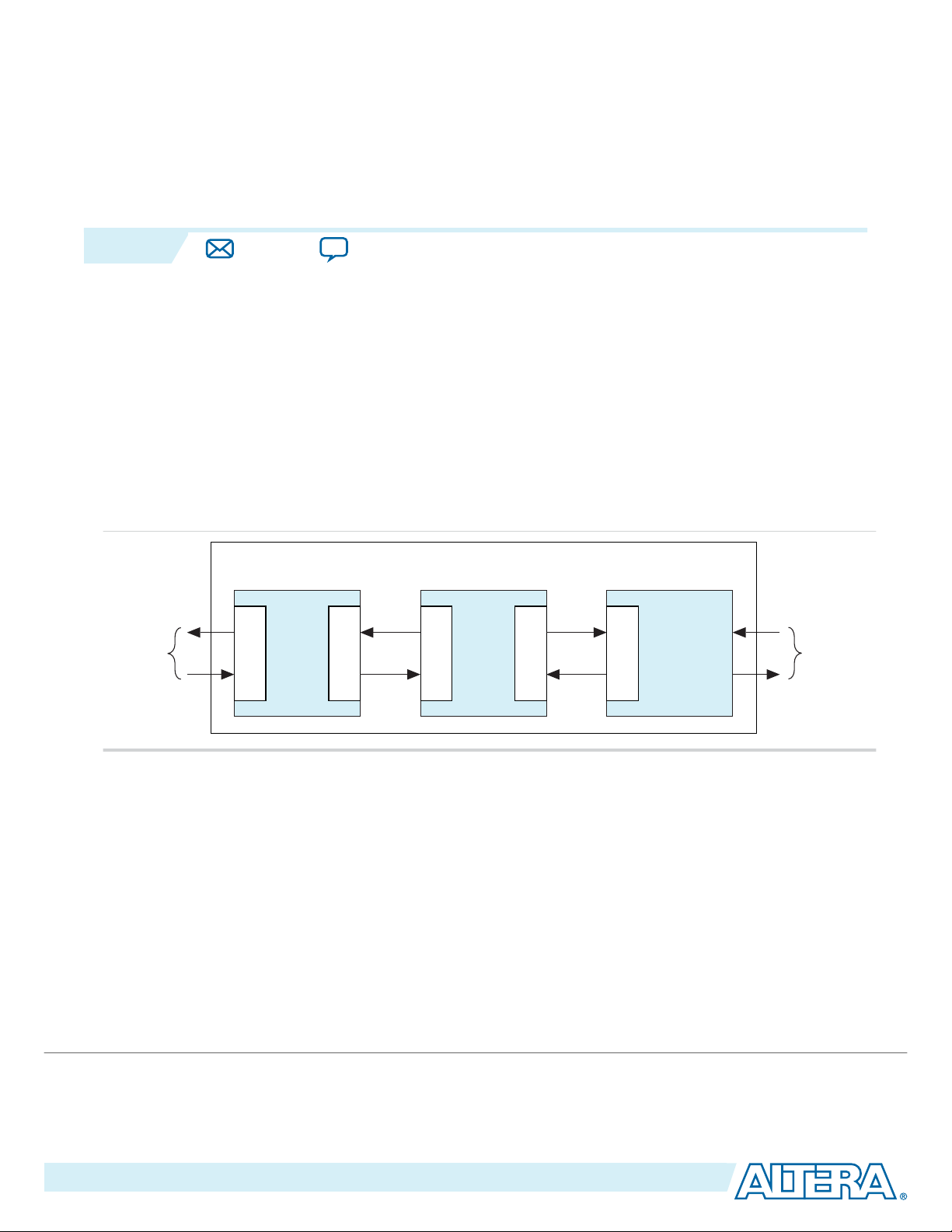
Interlaken is a high-speed serial communication protocol for chip-to-chip packet transfers. The Altera
100G Interlaken MegaCore® function implements the Interlaken Protocol Specification, Revision 1.2 . It
supports specific combinations of number of lanes (12 or 24) and lane rates from 6.25 gigabits per second
(Gbps) to 12.5 Gbps, on Stratix® V, Arria® V GZ, and Arria 10 devices, providing raw bandwidth of
123.75 Gbps to 150 Gbps.
Interlaken provides low I/O count compared to earlier protocols, supporting scalability in both number of
lanes and lane speed. Other key features include flow control, low overhead framing, and extensive
integrity checking. The 100G Interlaken MegaCore function incorporates a physical coding sublayer
(PCS), a physical media attachment (PMA), and a media access control (MAC) block.
Figure 1-1: Typical Interlaken Application
®
Related Information
Interlaken Protocol Specification, Revision 1.2
Features
The 100G Interlaken MegaCore function has the following features:
• Compliant with the Interlaken Protocol Specification, Rev 1.2.
• Supports 12 and 24 serial lanes in configurations that provide up to 150 Gbps raw bandwidth.
• Supports per-lane data rates of 6.25, 10.3125, and 12.5 Gbps using Altera on-chip high-speed
• Supports dynamically configurable BurstMax and BurstMin values.
©
2015 Altera Corporation. All rights reserved. ALTERA, ARRIA, CYCLONE, ENPIRION, MAX, MEGACORE, NIOS, QUARTUS and STRATIX words and logos are
trademarks of Altera Corporation and registered in the U.S. Patent and Trademark Office and in other countries. All other words and logos identified as
trademarks or service marks are the property of their respective holders as described at www.altera.com/common/legal.html. Altera warrants performance
of its semiconductor products to current specifications in accordance with Altera's standard warranty, but reserves the right to make changes to any
products and services at any time without notice. Altera assumes no responsibility or liability arising out of the application or use of any information,
product, or service described herein except as expressly agreed to in writing by Altera. Altera customers are advised to obtain the latest version of device
specifications before relying on any published information and before placing orders for products or services.
transceivers.
ISO
9001:2008
Registered
Page 6
1-2
IP Core Supported Combinations of Number of Lanes and Data Rate
• Supports Packet mode and Interleaved (Segmented) mode for user data transfer.
• Supports dual segment mode for efficient user data transfer.
• Supports up to 256 logical channels in out-of-the-box configuration.
• Supports optional user-controlled in-band flow control with 1, 2, 4, 8, or 16 16-bit calendar pages.
• Supports optional out-of-band flow control blocks.
• Supports memory block ECC in Stratix V and Arria 10 devices.
Related Information
Interlaken Protocol Specification, Rev 1.2
IP Core Supported Combinations of Number of Lanes and Data Rate
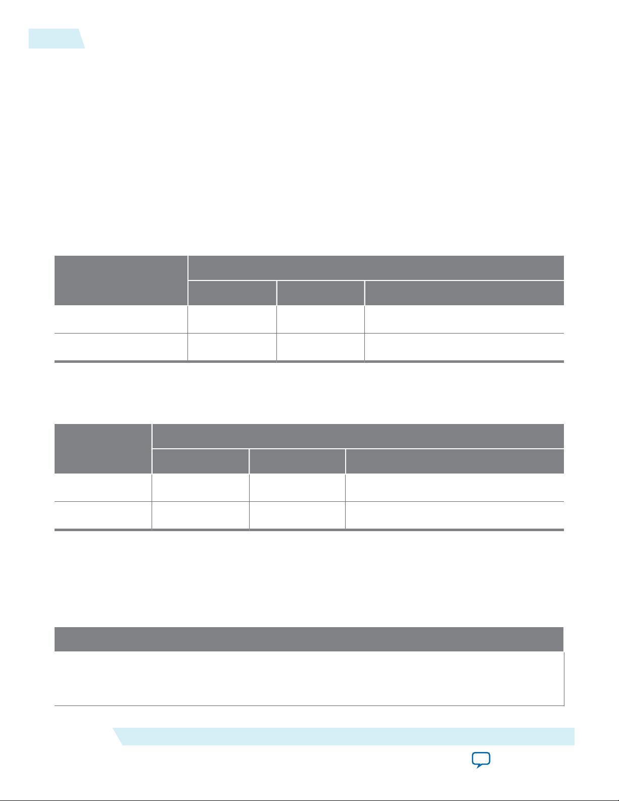
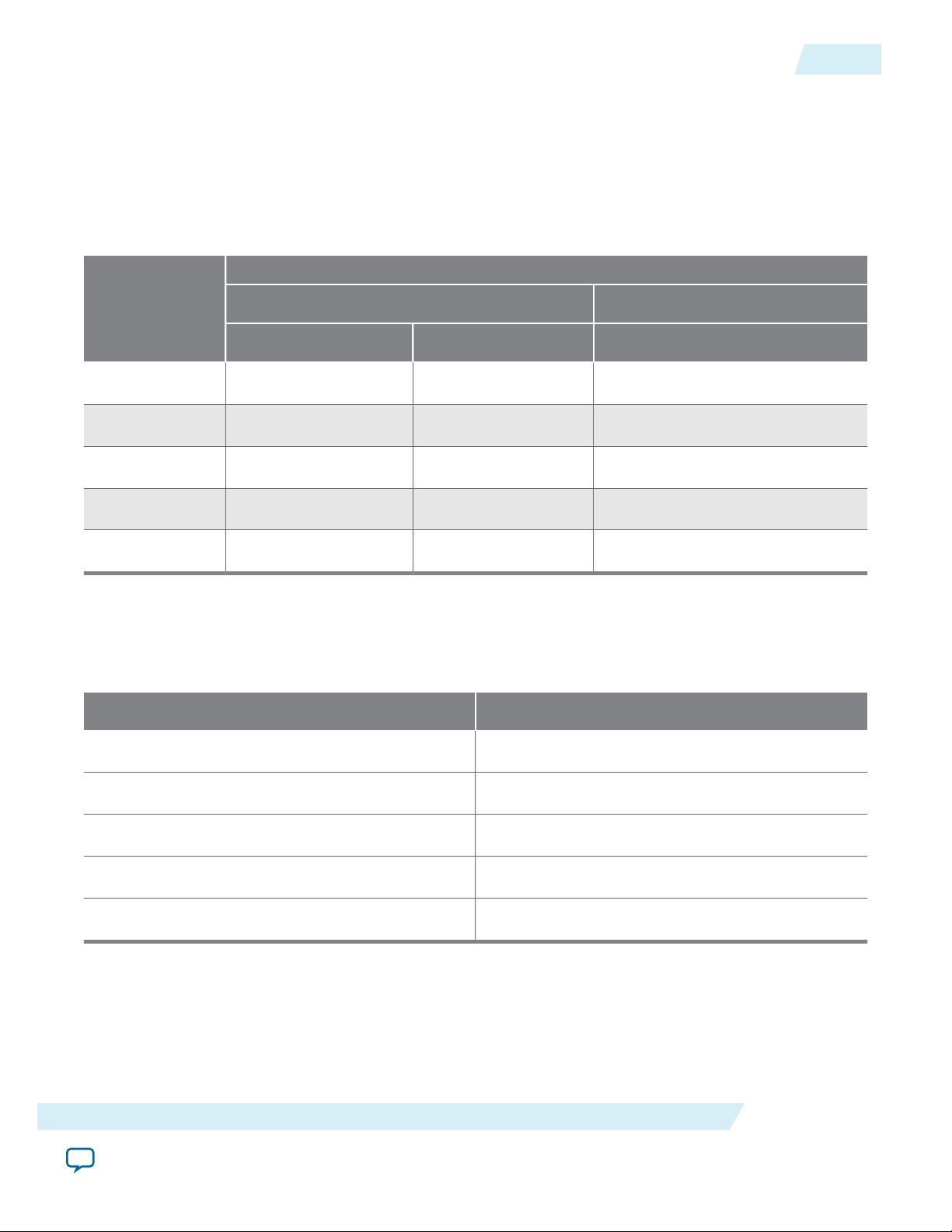
Table 1-1: 100G Interlaken IP Core Supported Combinations of Number of Lanes and Data Rate
Yes indicates a supported combination.
Lane Rate (Gbps)
Number of Lanes
6.25 10.3125 12.5
12 — Yes Yes
UG-01128
2015.05.04
24 Yes — —
IP Core Theoretical Raw Aggregate Bandwidth
Table 1-2: 100G Interlaken IP Core Theoretical Raw Aggregate Bandwidth in Gbps
Lane Rate (Gbps)
Number of Lanes
6.25 10.3125 12.5
12 — 123.75 150.00
24 150.00 — —
Device Family Support
The following table lists the device support level definitions for Altera IP cores.
Table 1-3: Altera IP Core Device Support Levels
FPGA Device Families
Preliminary support — The core is verified with preliminary timing models for this device family. The IP
core meets all functional requirements, but might still be undergoing timing analysis for the device family. It
can be used in production designs with caution.
Altera Corporation
About This MegaCore Function
Send Feedback
Page 7
UG-01128
2015.05.04
Final support — The IP core is verified with final timing models for this device family. The IP core meets all
functional and timing requirements for the device family and can be used in production designs.
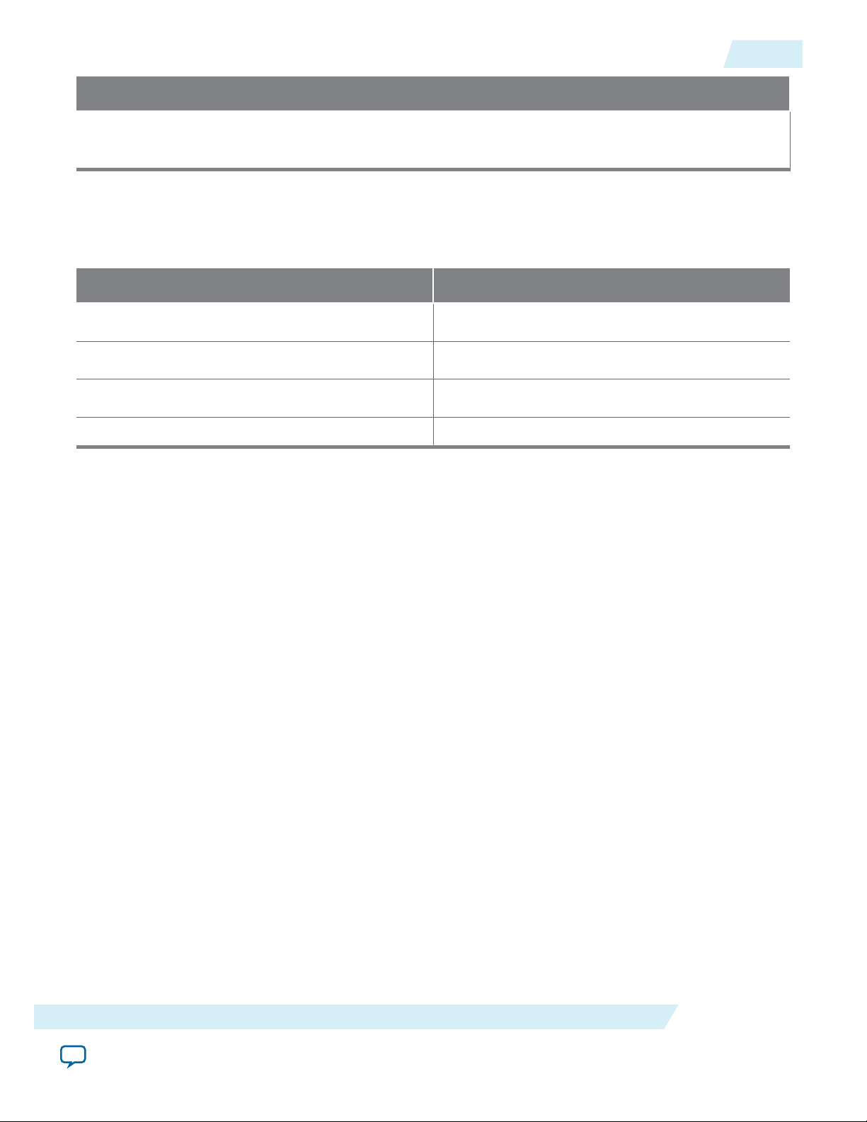
The following table shows the level of support offered by the 100G Interlaken MegaCore function for each
Altera device family.
Table 1-4: Device Family Support
Device Family Support
Stratix V (GS, GT, and GX) Final
Arria V (GZ) Final
Arria 10 Preliminary
Other device families No support
FPGA Device Families
IP Core Verification
1-3
IP Core Verification
Before releasing a version of the 100G Interlaken IP core, Altera runs comprehensive regression tests in
the current version of the Quartus® II software. These tests use standalone methods. These files are tested
in simulation and hardware to confirm functionality. Altera tests and verifies the 100G Interlaken IP core
in hardware for different platforms and environments.
Constrained random techniques generate appropriate stimulus for the functional verification of the IP
core. Functional coverage metrics measure the quality of the random stimulus, and ensure that all
important features are verified.
Performance and Resource Utilization
About This MegaCore Function
Send Feedback
Altera Corporation
Page 8
1-4
Performance and Resource Utilization
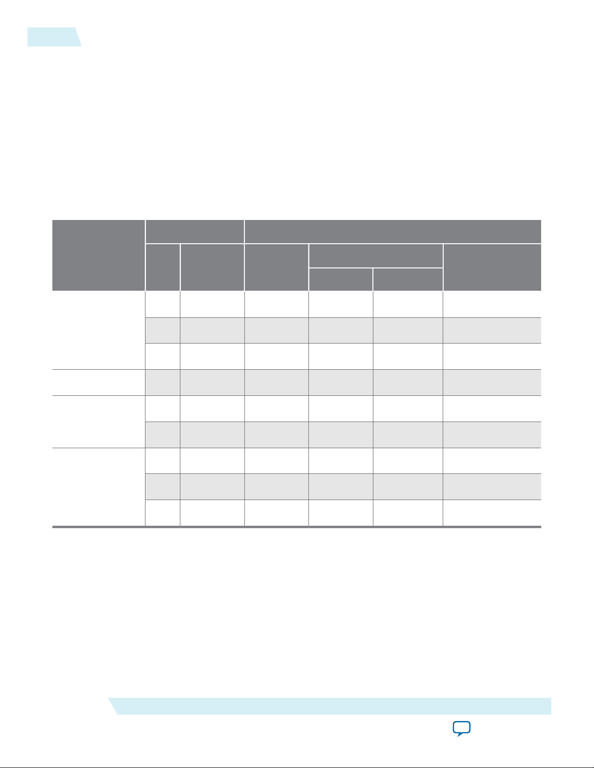
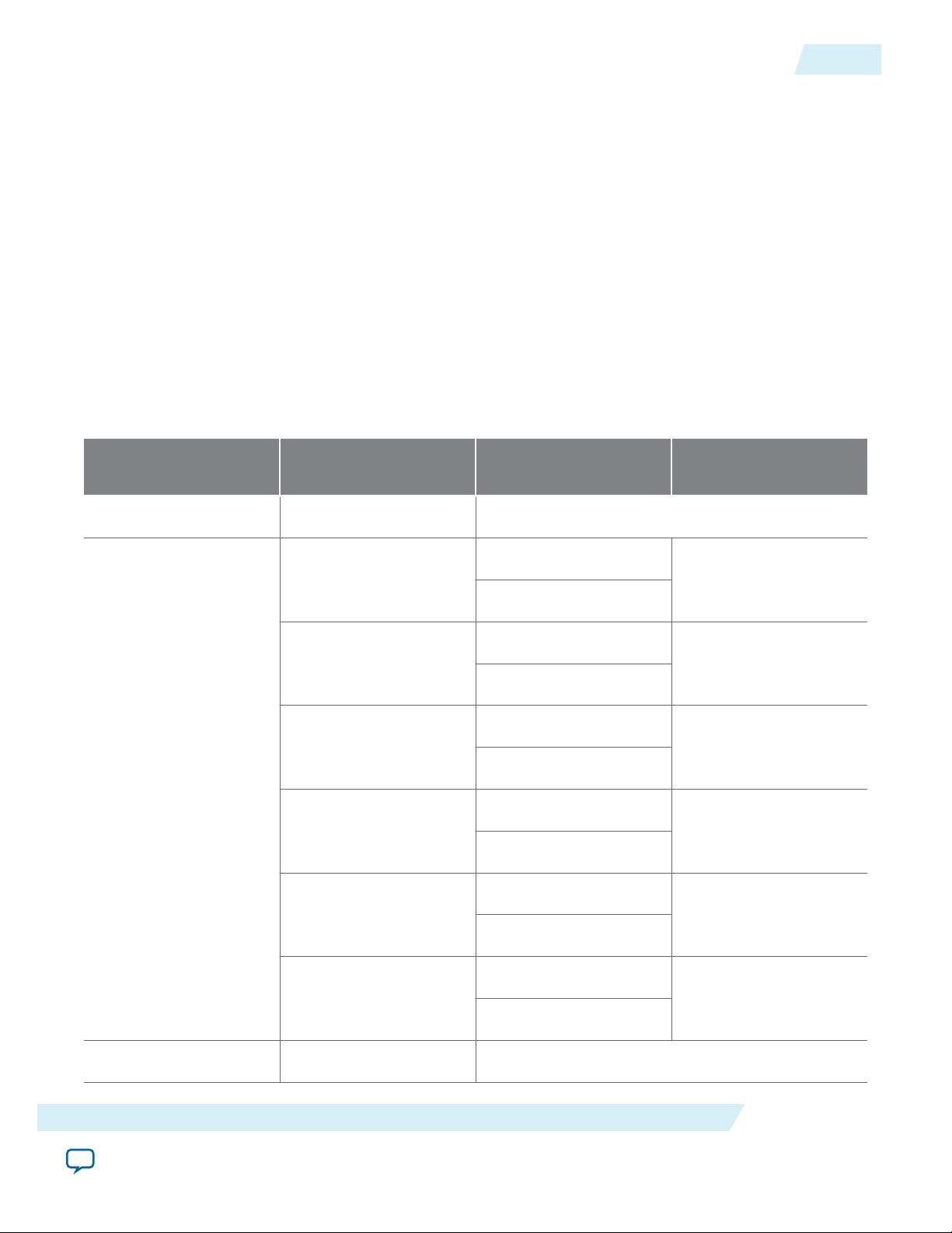
Table 1-5: 100G Interlaken MegaCore Function FPGA Resource Utilization
Lists the resources and expected performance for selected variations of the 100G Interlaken IP core using the
Quartus II software v13.1 and v13.1 Arria 10 edition releases for the following devices:
• Arria 10 device 10AX115S2F45I2SGES
• Arria V GZ device 5AGZE1H2F35I3
• Stratix V GX device 5SGXMA7N2F45I3
• Stratix V GT device 5SGTMC7K3F40I2
The results in this table do not include the out-of-band flow control block.
The numbers of ALMs and logic registers are rounded up to the nearest 100. The numbers of ALMs, before
rounding, are the ALMs needed numbers from the Quartus II Fitter Report.
Parameters Resource Utilization
UG-01128
2015.05.04
Device
Numb
er of
Lanes
Per‑Lane
Data Rate
(Gbps)
ALMs
Needed
Logic Registers
Primary Secondary
12 10.3125 17500 34100 1800 38
Arria 10
12 12.500 17600 34100 1900 38
24 6.25 26100 48500 3200 38
Arria V GZ 12 10.3125 17300 34100 2500 38
12 10.3125 17200 34200 2300 38
Stratix V GX
24 6.250 25100 47600 3200 38
12 10.3125 17200 34200 2400 38
Stratix V GT
12 12.500 17300 34100 2600 38
24 6.250 2500 47600 3100 38
M20K Blocks
Related Information
• Fitter Resources Reports in the Quartus II Help
• Quartus II Handbook, Volume 1: Design and Synthesis
Altera Corporation
Information about Quartus II resource utilization reporting for 28-nm devices, including ALMs
needed.
Includes information about how to apply the Speed setting.
About This MegaCore Function
Send Feedback
Page 9
UG-01128
2015.05.04
Device Speed Grade Support
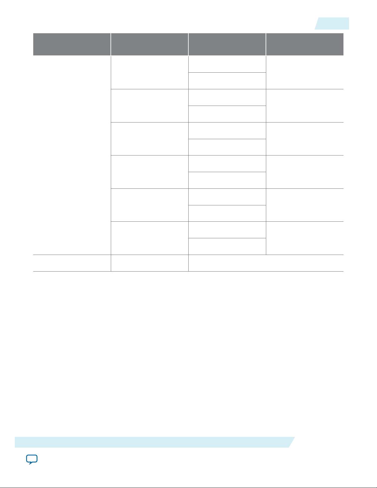
Device Speed Grade Support
Table 1-6: Minimum Recommended Device Family Speed Grades
For each device family the 100G Interlaken IP core supports, Altera recommends that you configure the
100G Interlaken IP core only in the device speed grades listed in the table, and any faster (lower numbered) device
speed grades that are available. Altera does not support configuration of this IP core in slower speed grades.
IP Core Variation
1-5
Device Family
10.3125 Gbps 12.5 Gbps 6.25 Gbps
12 Lanes 24 Lanes
Arria 10 I2, E2 I2, E2 I2, E2
Arria V GZ I3, C3 — I3, C3
Stratix V GX I3, C3 I2, C2 I3, C3
Stratix V GT I3, C3 I2, C2 I3, C3
Stratix V GS I3, C3 I2, C2 I3, C3
Release Information
Table 1-7: 100G Interlaken MegaCore Function Release Information
Item Value
Version 15.0
Release Date May 2015
Ordering Code IP–ILKN/100G
Vendor ID 6AF7
Product ID 00D6
Altera verifies that the current version of the Quartus II software compiles the previous version of each
MegaCore function, if this MegaCore function was included in the previous release. Any exceptions to
this verification are reported in the Altera IP Core Release Notes. Altera does not verify compilation with
MegaCore function versions older than the previous release.
A 100G Interlaken IP core with optimized feature set or low resource utilization is available by request.
About This MegaCore Function
Send Feedback
Altera Corporation
Page 10

1-6
Release Information
Related Information
Altera IP Core Release Notes
UG-01128
2015.05.04
Altera Corporation
About This MegaCore Function
Send Feedback
Page 11
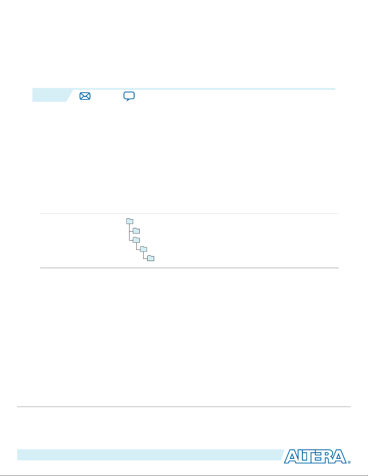
Getting Started With the 100G Interlaken IP
acds
quartus - Contains the Quartus II software
ip - Contains the Altera IP Library and third-party IP cores
altera - Contains the Altera IP Library source code
<IP core name> - Contains the IP core source files
www.altera.com
101 Innovation Drive, San Jose, CA 95134
2015.05.04
UG-01128
Subscribe
Send Feedback
The following sections explain how to install, parameterize, simulate, and initialize the 100G Interlaken IP
core.
Installing and Licensing IP Cores
The Altera IP Library provides many useful IP core functions for your production use without purchasing
an additional license. Some Altera MegaCore® IP functions require that you purchase a separate license
for production use. However, the OpenCore® feature allows evaluation of any Altera® IP core in
simulation and compilation in the Quartus II software. After you are satisfied with functionality and
perfformance, visit the Self Service Licensing Center to obtain a license number for any Altera product.
Figure 2-1: IP Core Installation Path
Core
2
Note:
The default IP installation directory on Windows is <drive>:\altera\<version number>; on Linux it is
<home directory>/altera/ <version number>.
Related Information
• Altera Licensing Site
• Altera Software Installation and Licensing Manual
OpenCore Plus IP Evaluation
Altera's free OpenCore Plus feature allows you to evaluate licensed MegaCore IP cores in simulation and
hardware before purchase. You need only purchase a license for MegaCore IP cores if you decide to take
your design to production. OpenCore Plus supports the following evaluations:
©
2015 Altera Corporation. All rights reserved. ALTERA, ARRIA, CYCLONE, ENPIRION, MAX, MEGACORE, NIOS, QUARTUS and STRATIX words and logos are
trademarks of Altera Corporation and registered in the U.S. Patent and Trademark Office and in other countries. All other words and logos identified as
trademarks or service marks are the property of their respective holders as described at www.altera.com/common/legal.html. Altera warrants performance
of its semiconductor products to current specifications in accordance with Altera's standard warranty, but reserves the right to make changes to any
products and services at any time without notice. Altera assumes no responsibility or liability arising out of the application or use of any information,
product, or service described herein except as expressly agreed to in writing by Altera. Altera customers are advised to obtain the latest version of device
specifications before relying on any published information and before placing orders for products or services.
ISO
9001:2008
Registered
Page 12

2-2
Specifying the 100G Interlaken IP Core Parameters and Options
• Simulate the behavior of a licensed IP core in your system.
• Verify the functionality, size, and speed of the IP core quickly and easily.
• Generate time-limited device programming files for designs that include IP cores.
• Program a device with your IP core and verify your design in hardware.
OpenCore Plus evaluation supports the following two operation modes:
• Untethered—run the design containing the licensed IP for a limited time.
• Tethered—run the design containing the licensed IP for a longer time or indefinitely. This requires a
connection between your board and the host computer.
Note: All IP cores that use OpenCore Plus time out simultaneously when any IP core in the design times
out.
Specifying the 100G Interlaken IP Core Parameters and Options
The parameter editor GUI allows you to quickly configure your custom IP variation. You specify IP core
options and parameters in the Quartus II software.
The 100G Interlaken IP core is not supported in Qsys. You must use the IP Catalog accessible from the
Quartus II Tools menu.
The 100G Interlaken IP core does not support VHDL simulation models. Altera recommends that you
specify the Verilog HDL for both synthesis and simulation models.
UG-01128
2015.05.04
1. In the IP Catalog (Tools > IP Catalog), locate and double-click the name of the IP core to customize.
The parameter editor appears.
2. Specify a top-level name for your custom IP variation. The parameter editor saves the IP variation
settings in a file named <your_ip>.qsys. Click OK.
Note:
For Arria V GZ and Stratix V variations, you are prompted to specify an IP variation file type.
To generate the demonstration testbench and example design, you must select the Verilog HDL
and specify the Verilog file extension (.v).
3. Specify the parameters and options for your IP variation in the parameter editor, including one or
more of the following. Refer to 100G Interlaken IP Core Parameter Settings for information about
specific IP core parameters.
• Specify parameters defining the IP core functionality, port configurations, and device-specific
features.
• Specify options for processing the IP core files in other EDA tools.
4. For Arria 10 variations, follow these steps:
a. Click Generate HDL. The Generation dialog box appears.
b. Specify output file generation options, and then click Generate. The IP variation files generate
according to your specifications.
Note:
To generate the demonstration testbench and example design, you must specify Verilog
HDL for both synthesis and simulation models.
c. Click Finish. The parameter editor adds the top-level .qsys file to the current project automatically.
If you are prompted to manually add the .qsys file to the project, click Project > Add/Remove Files
in Project to add the file.
5. For Arria V GZ and Stratix V variations, follow these steps:
Altera Corporation
Getting Started With the 100G Interlaken IP Core
Send Feedback
Page 13
Notes:
1. If supported and enabled for your IP variation
2. If functional simulation models are generated
3. If example design is generated
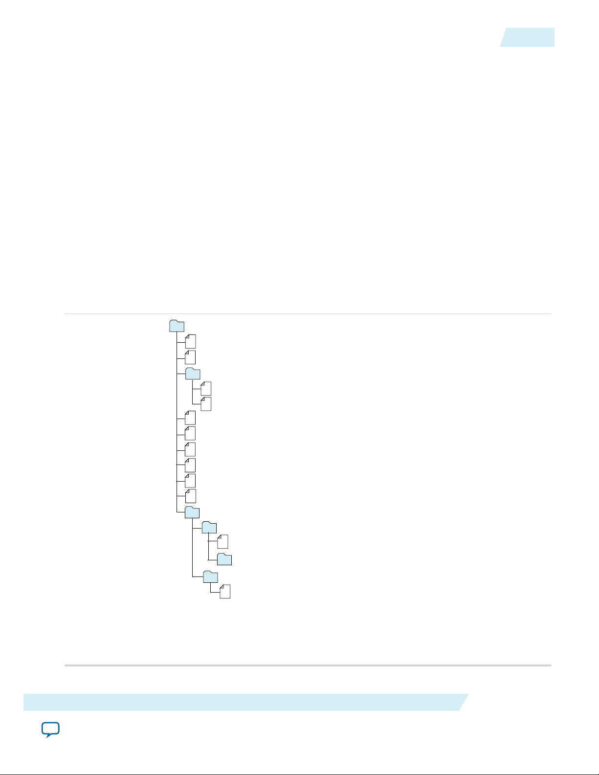
<Project Directory>
<your_ip>_sim
1
ilk_core.sv - IPFS model
2
<simulator_vendor>
<simulator setup scripts>
<your_ip>.qip - Quartus II IP integration file
<your_ip>.sip - Lists files for simulation
<your_ip>.v, .sv. or .vhd - Top-level IP synthesis file
ilk_core
<your_ip>.cmp - VHDL component declaration file
<your_ip>.bsf - Block symbol schematic file
<your_ip> - IP core synthesis files
ilk_core.sv
- HDL synthesis file
ilk_top.sdc - Timing constraints file
<your_ip>.ppf - XML I/O pin information file
<your_ip>.spd - Combines individual simulation scripts
1
<your_ip>_sim.f - Refers to simulation models and scripts
1
testbench
3
UG-01128
2015.05.04
Files Generated for Arria V GZ and Stratix V Variations
a. Click Finish. The Generation dialog box appears.
b. Click Exit. The parameter editor adds the top-level .qsys file to the current project automatically. If
you are prompted to manually add the .qsys file to the project, click Project > Add/Remove Files in
Project to add the file.
6. After generating and instantiating your IP variation, make appropriate pin assignments to connect
ports.
If you specify the Verilog HDL for your IP core files, the Quartus II software creates the demonstration
testbench and example design when it generates the IP core.
Related Information
100G Interlaken IP Core Parameter Settings on page 3-1
Details about the parameters available in the 100G Interlaken parameter editor.
Files Generated for Arria V GZ and Stratix V Variations
The Quartus II software generates multiple files during generation of your 100G Interlaken IP core Arria
V GZ or Stratix V variation.
Figure 2-2: IP Core Generated Files
2-3
Getting Started With the 100G Interlaken IP Core
Send Feedback
Altera Corporation
Page 14

2-4
Files Generated for Arria 10 Variations
If you select the Verilog HDL for synthesis and simulation models, the demonstration testbench and
example design files are located in <your_ip>_sim/ilk_core/testbench.
Files Generated for Arria 10 Variations
The Quartus II software generates multiple files during generation of your 100G Interlaken IP core Arria
10 variation.
UG-01128
2015.05.04
Altera Corporation
Getting Started With the 100G Interlaken IP Core
Send Feedback
Page 15
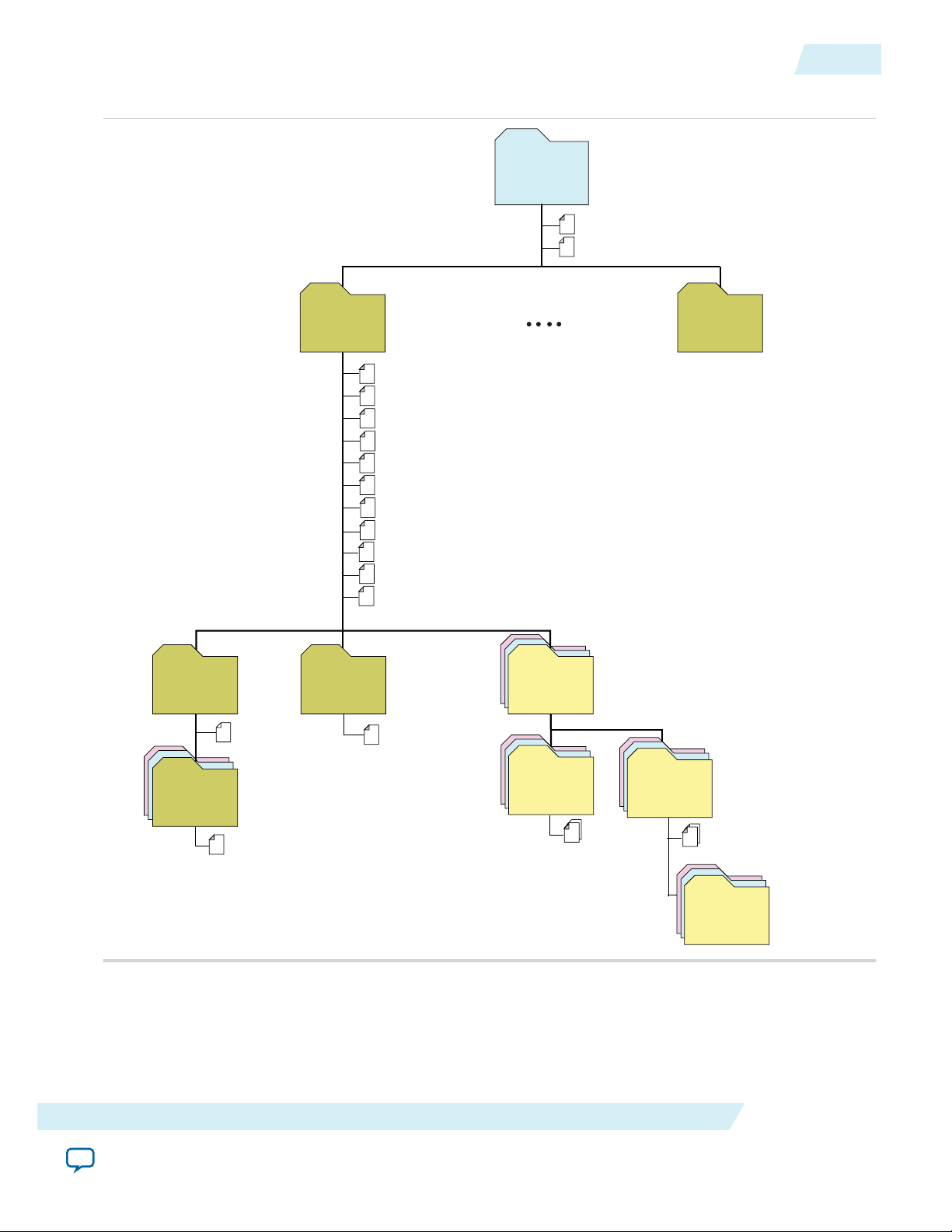
<your_ip >.cmp - VHDL component declaration file
<your_ip >.ppf - XML I/O pin information file
<your_ip >.qip - Lists IP synthesis files
<your_ip >.sip - Lists files for simulation
<your_ip >.v or .vhd
Top-level IP synthesis file
<your_ip >.v or .vhd
Top-level simulation file
<simulator_setup_scripts >
<your_ip >.qsys - System or IP integration file
<your_ip >_bb.v - Verilog HDL black box EDA synthesis file
<your_ip >_inst.v or .vhd - Sample instantiation template
<your_ip >_generation.rpt - IP generation report
<your_ip >.debuginfo - Contains post-generation information
<your_ip >.html - Connection and memor y map data
<your_ip >.bsf - Block symbol schematic
<your_ip >.spd - Combines individual simulation scripts
<your_ip >.sopcinfo - Software tool-chain integration file
<project directory>
<your_ip>
IP variation files
sim
Simulation files
synth
IP synthesis files
<EDA tool name>
Simulator scripts
ilk_core_<version>
Subcore libraries
sim
Subcore
Simulation files
synth
Subcore
synthesis files
<HDL files >
<HDL files >
<your_ip> n
IP variation files
testbench
Testbench files
UG-01128
2015.05.04
Figure 2-3: IP Core Generated Files
Files Generated for Arria 10 Variations
2-5
If you select the Verilog HDL for synthesis and simulation models, the demonstration testbench and
example design files are located in <your_ip>/ilk_core_<version>/sim/testbench.
.
Getting Started With the 100G Interlaken IP Core
Send Feedback
Altera Corporation
Page 16

2-6
Simulating the100G Interlaken IP Core
Simulating the100G Interlaken IP Core
You can simulate your 100G Interlaken MegaCore function variation using any of the vendor-specific
IEEE encrypted functional simulation models which are generated in the new <instance name>_sim
subdirectory of your project directory.
The 100G Interlaken MegaCore function supports the Synopsys VCS, Cadence NC Sim, and Mentor
Graphics Modelsim-SE simulators.
The 100G Interlaken IP core generates only a Verilog HDL simulation model and testbench. The IP core
parameter editor appears to offer you the option of generating a VHDL simulation model, but this IP core
does not support a VHDL simulation model or testbench.
For more information about functional simulation models for Altera IP cores, refer to the Simulating
Altera Designs chapter in volume 3 of the Quartus II Handbook.
If you specify the models are in Verilog HDL when you parameterize your IP core variation, the Quartus
II software generates a testbench which demonstrates the resetting, clocking, and toggling of the
100G Interlaken IP core user interfaces.
Related Information
UG-01128
2015.05.04
• 100G Interlaken IP Core Testbench on page 7-1
When you generate the IP core, the Quartus II software generates a testbench.
• Simulating Altera Designs
Integrating Your IP Core in Your Design
After you generate your 100G Interlaken IP core variation, you can instantiate it in the RTL for your
design. When you integrate your IP core instance in your design, you must pay attention to the following
items.
Pin Assignments
When you integrate your 100G Interlaken MegaCore function instance in your design, you must make
appropriate pin assignments. You do not need to specify pin assignments for simulation. However, you
should make the pin assignments before you compile, to provide direction to the Quartus II Fitter and to
specify the signals that should be assigned to device pins.
You can create a virtual pin to avoid making specific pin assignments for top-level signals while you are
simulating and not ready to map the design to hardware. Do not create virtual pins for clock or Interlaken
link data signals.
For the Arria 10 device family, you must configure a PLL external to the 100G Interlaken IP core. The
required number of PLLs depends on the distribution of your Interlaken lane data pins in the different
A10 transceiver blocks.
Related Information
Quartus II Help
For information about the Quartus II software, including virtual pins.
Altera Corporation
Getting Started With the 100G Interlaken IP Core
Send Feedback
Page 17
UG-01128
2015.05.04
Transceiver Logical Channel Numbering
Transceiver Logical Channel Numbering
In Arria V and Stratix V devices, logical channel numbering starts from zero. The logical channel
numbering starts at the bottom of the die with logical channel 0 and continues in physical pin order
through the four ordered transceiver blocks on the same side of the device. Each data channel and TX PLL
has its own dedicated reconfiguration interface with an assigned logical channel.
In Arria 10 devices, you control the mapping of Interlaken lanes directly in the Arria 10 Native PHY IP
core that is included in the 100G Interlaken IP core.
In Arria V and Stratix V devices, you can control the logical channel assignments in the IP core. You
typically assign lanes to match the logical channel numbering. However, you can map the twelve
Interlaken lanes in a 12-lane variation to any two adjacent transceiver blocks on the same side of the
device. You can use the information in the following table to map the lanes to their default logical channel
numbering. The logical channel numbering always starts at the bottom of a transceiver block.
Table 2-1: Transceiver Logical Channel Numbering
The default expected mapping of logical channels to Interlaken lanes in Arria V and Stratix V devices.
2-7
Transceiver Block Number Logical Channel Number in
Device
27 TX PLL 3
26
25
24
3
23
22
Direction Interlaken Lane Number in
IP Core
TX
23
RX
TX
22
RX
TX
21
RX
TX
20
RX
TX
19
RX
21
20 TX PLL 2
Getting Started With the 100G Interlaken IP Core
Send Feedback
TX
18
RX
Altera Corporation
Page 18

2-8
Transceiver Logical Channel Numbering
UG-01128
2015.05.04
Transceiver Block Number Logical Channel Number in
Device
19
18
17
2
16
15
Direction Interlaken Lane Number in
IP Core
TX
17
RX
TX
16
RX
TX
15
RX
TX
14
RX
TX
13
RX
TX
14
RX
13 TX PLL 1
12
Altera Corporation
Getting Started With the 100G Interlaken IP Core
Send Feedback
Page 19
UG-01128
2015.05.04
Transceiver Logical Channel Numbering
2-9
Transceiver Block Number Logical Channel Number in
Device
12
11
10
1
9
8
Direction Interlaken Lane Number in
IP Core
TX
11
RX
TX
10
RX
TX
9
RX
TX
8
RX
TX
7
RX
TX
7
RX
6 TX PLL 0
6
Getting Started With the 100G Interlaken IP Core
Send Feedback
Altera Corporation
Page 20
2-10
Adding the Reconfiguration Controller
UG-01128
2015.05.04
Transceiver Block Number Logical Channel Number in
Device
5
4
3
0
2
1
Direction Interlaken Lane Number in
IP Core
TX
5
RX
TX
4
RX
TX
3
RX
TX
2
RX
TX
1
RX
0
For example, in an Arria V or Stratix V device, to change the VOD setting for lane 9, you write logical
channel 10 to the Reconfiguration Controller.
Related Information
Altera Transceiver PHY IP User Guide
Background information to better understand logical channel numbering.
Adding the Reconfiguration Controller
100G Interlaken IP core variations that target an Arria V or a Stratix V device require an external reconfi‐
guration controller to function correctly in hardware. 100G Interlaken IP core variations that target an
Arria 10 device include a reconfiguration controller block and do not require an external reconfiguration
controller.
Keeping the Reconfiguration Controller external to the IP core in Arria V and Stratix V devices provides
the flexibility to share the Reconfiguration Controller among multiple IP cores and to accommodate
FPGA transceiver layouts based on the usage model of your application. In Arria 10 devices, you can
configure individual transceiver channels flexibly through an Avalon-MM Arria 10 transceiver reconfigu‐
ration interface.
TX
0
RX
Altera Corporation
Getting Started With the 100G Interlaken IP Core
Send Feedback
Page 21

UG-01128
2015.05.04
The following simple instructions show you how to instantiate an Altera Transceiver Reconfiguration
Controller and how to connect the design blocks:
Generating the Reconfiguration Controller
You can use the IP Catalog to generate an Altera Transceiver Reconfiguration Controller.
In the Transceiver Reconfiguration Controller parameter editor, you select the features of the transceiver
that can be dynamically reconfigured. However, you must ensure that the following two features are
turned on:
1. Enable PLL calibration
2. Enable Analog controls
You must also set the value of the Number of reconfiguration interfaces parameter. Each TX PLL
requires its own reconfiguration interface, whether or not you intend to reconfigure it. The following
formula determines the correct number of reconfiguration interfaces:
NUMBER_OF_RECONFIGURATION_INTERFACES = NUMBER_OF_LANES + NUMBER_OF_TX_PLLs
where
• NUMBER_OF_LANES is the total number of physical lanes used in your implemented design.
• NUMBER_OF_TX_PLLs is the total number of transceiver blocks (number of TX PLLs) used in your
design.
Generating the Reconfiguration Controller
2-11
For example, for a design that includes a 12-lane Interlaken variation that is configured in two transceiver
blocks, you must set Number of reconfiguration interfaces to the value of 14.
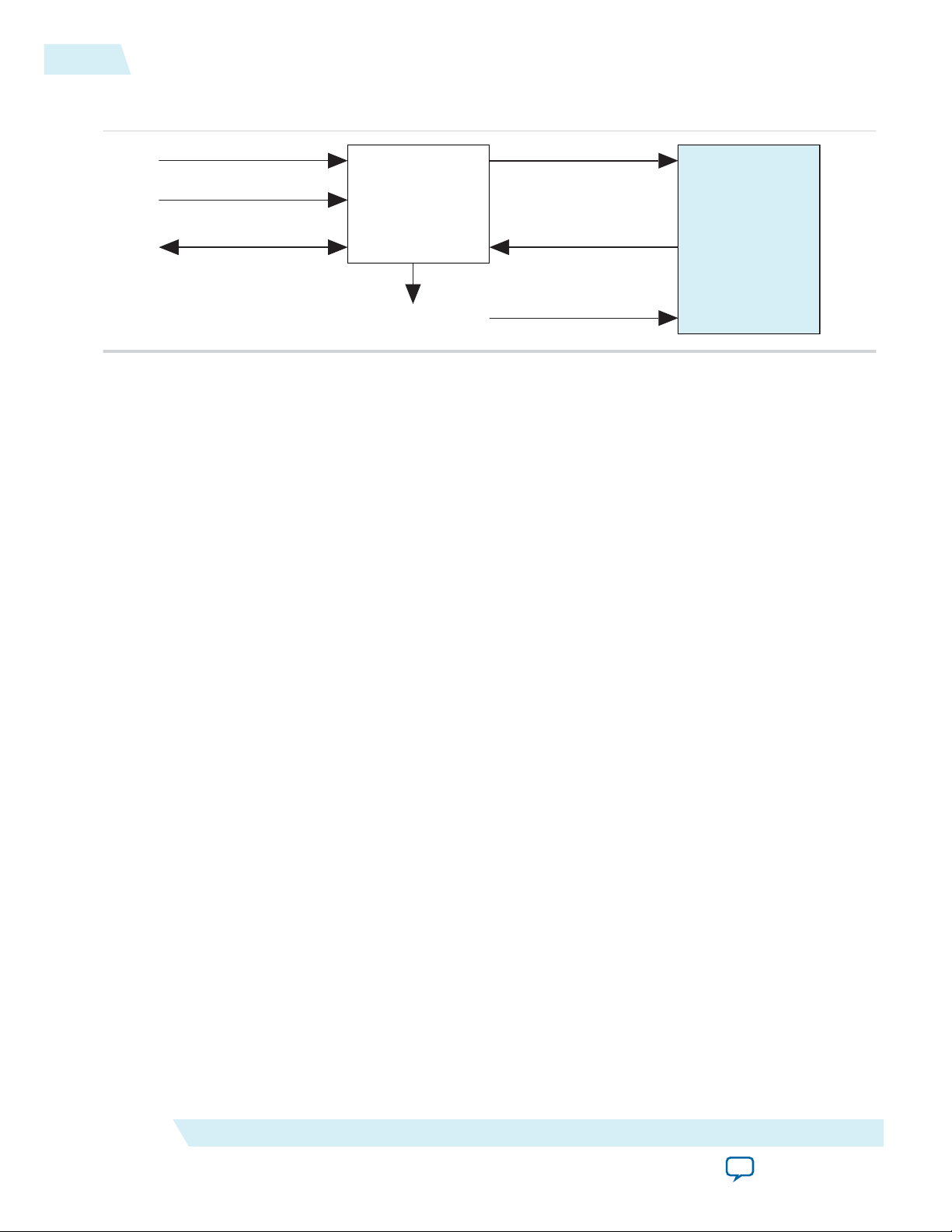
Connecting the Reconfiguration Controller to the IP Core
The Reconfiguration Controller communicates with the 100G Interlaken IP core on two busses:
• reconfig_to_xcvr (output)
• reconfig_from_xcvr (input)
Each of these busses connects to the bus of the same name in the 100G Interlaken IP core.
You must also connect the following signals:
• mgmt_clk_clk: Reconfiguration Controller clock (input)
• mgmt_rst_reset: Reconfiguration Controller reset (input)
• reconfig_busy: Reconfiguration Controller busy indication (output)
Getting Started With the 100G Interlaken IP Core
Send Feedback
Altera Corporation
Page 22
100G Interlaken
MegaCore
Function
Reconfiguration
Controller
mgmt_clk_clk
mgmt_rst_reset
Avalon-MM IF
reconfig_to_xcvr
reconfig_from_xcvr
reconfig_busy
reset_n
2-12
Adding the External PLL
Figure 2-4: Typical Connection of Reconfiguration Controller to 100G Interlaken IP Core
Altera recommends that you set the Reconfiguration Controller input clock frequency in the range of 100
MHz to 125 MHz. Refer to the Altera Transceiver PHY IP Core User Guide for frequency range require‐
ments specific to the device family.
The Reconfiguration Controller reset input should be asserted high during power up and remain asserted
until its clock input becomes stable. Upon power up, the Reconfiguration Controller asserts
reconfig_busy output high. The reconfig_busy signal remains asserted until the Reconfiguration
Controller completes the configuration of all transceivers.
UG-01128
2015.05.04
Related Information
• Altera Transceiver PHY IP Core User Guide
Adding the External PLL
100G Interlaken IP core variations that target an Arria 10 device require an external transceiver PLL to
function correctly in hardware. 100G Interlaken IP core variations that target an Arria V or Stratix V
device include the transceiver PLLs and do not require that you configure any additional PLLs.
You can use the IP Catalog to generate an external PLL IP core that configures a TX PLL on the device.
• Select Arria 10 Transceiver ATX PLL, Arria 10 Transceiver CMU PLL, or Arria 10 FPLL.
• In the parameter editor, set the following parameter values:
• PLL output frequency to one half the per-lane data rate of the IP core variation. The transceiver
performs dual edge clocking, using both the rising and falling edges of the input clock from the
PLL. Therefore, this PLL output frequency setting drives the transceiver with the correct clock for
the Interlaken lanes.
• PLL reference clock frequency to a frequency at which you can drive the TX PLL input reference
clock. You must drive the external PLL reference clock input signal at the frequency you specify for
this parameter.
The number of external PLLs you must define depends on the distribution of your Interlaken TX serial
lines across physical transceiver channels. You specify the clock network to which each PLL output
connects by setting the clock network in the PLL parameter editor.
Altera Corporation
Getting Started With the 100G Interlaken IP Core
Send Feedback
Page 23
ATX PLL
ATX PLL
ATX PLL
ATX PLL
pll_powerdown
100G Interlaken IP Core
Txvr Block N
Txvr Block N+1
tx_pll_locked
tx_pll_powerdown
tx_serial_clk[11] (Channel 5) (Lane 11)
tx_serial_clk[10] (Channel 4) (Lane 10)
tx_serial_clk[9] (Channel 3) (Lane 9)
tx_serial_clk[8] (Channel 2) (Lane 8)
tx_serial_clk[7] (Channel 1) (Lane 7)
tx_serial_clk[6] (Channel 0) (Lane 6)
tx_serial_clk[5] (Channel 5) (Lane 5)
tx_serial_clk[4] (Channel 4) (Lane 4)
tx_serial_clk[3] (Channel 3) (Lane 3)
tx_serial_clk[2] (Channel 2) (Lane 2)
tx_serial_clk[1] (Channel 1) (Lane 1)
tx_serial_clk[0] (Channel 0) (Lane 0)
pll_locked
pll_cal_busy
tx_serial_clk
(12 Lanes)
UG-01128
2015.05.04
Adding the External PLL
You must connect the external PLL signals and the Arria 10 100G Interlaken IP core transceiver Tx PLL
interface signals according to the following rules:
• Connect the tx_serial_clk input pin for each Interlaken lane to the output port of the same name in
the corresponding external PLL.
• Connect the tx_pll_locked input pin of the 100G Interlaken IP core to the logical AND of the
pll_locked output signals of the external PLLs for all of the Interlaken lanes and the inverse of each of
the pll_cal_busy signals from the external PLLs.
• Connect the tx_pll_powerdown output pin of the 100G Interlaken IP core to the pll_powerdown reset
pin of the external PLLs for all of the Interlaken lanes.
User logic must provide the AND function and connections. The following figure provides an example of
one correct method, among many, to implement connection logic. You can also refer to the example
design for example working user logic including one correct method to instantiate and connect an
external PLL.
Figure 2-5: Example Connection of ATX PLL with 100G Interlaken IP Core Using Arria 10 xN Clock
Network
2-13
Related Information
• Arria 10 External PLL Interface on page 4-3
• 100G Interlaken IP Core Testbench on page 7-1
Getting Started With the 100G Interlaken IP Core
Send Feedback
Altera Corporation
Page 24

2-14
Compiling the Full Design and Programming the FPGA
• Pin Assignments on page 2-6
• Arria 10 External PLL Interface Signals on page 5-15
• Arria 10 Transceiver PHY User Guide
Information about the correspondence between PLLs and transceiver channels, and information about
how to configure an external PLL for your own design. You specify the clock network to which the
PLL output connects by setting the clock network in the PLL parameter editor.
Compiling the Full Design and Programming the FPGA
You can use the Start Compilation command on the Processing menu in the Quartus II software to
compile your design. After successfully compiling your design, program the targeted Altera device with
the Programmer and verify the design in hardware.
Related Information
• Quartus II Incremental Compilation for Hierarchical and Team-Based Design
Information about compiling your design. Chapter in volume 1 of the Quartus II Handbook.
• Quartus II Programmer
Information about programming the device. Chapter in volume 3 of the Quartus II Handbook.
UG-01128
2015.05.04
Altera Corporation
Getting Started With the 100G Interlaken IP Core
Send Feedback
Page 25

2015.05.04
www.altera.com
101 Innovation Drive, San Jose, CA 95134
100G Interlaken IP Core Parameter Settings
3
UG-01128
Subscribe
Send Feedback
You customize the 100G Interlaken IP core by specifying parameters in the 100G Interlaken parameter
editor, which you access from the Quartus II IP Catalog.
This chapter describes the parameters and how they affect the behavior of the IP core. To customize your
100G Interlaken IP core, you can modify parameters to specify the following properties:
Number of Lanes on page 3-1
Meta Frame Length in Words on page 3-2
Data Rate on page 3-2
Transceiver Reference Clock Frequency on page 3-2
Include Advanced Error Reporting and Handling on page 3-3
Enable M20K ECC Support on page 3-4
Include Diagnostic Features on page 3-4
Include In-Band Flow Control Block on page 3-5
Number of Calendar Pages on page 3-5
TX Scrambler Seed on page 3-5
Transfer Mode Selection on page 3-6
Data Format on page 3-6
Number of Lanes
The Number of lanes parameter specifies the number of lanes available for Interlaken communication.
The supported values are 12 and 24.
The default value of the Number of lanes parameter is 12.
The 100G Interlaken MegaCore function supports various combinations of number of lanes and lane
rates. Ensure that your parameter settings specify a supported combination.
©
2015 Altera Corporation. All rights reserved. ALTERA, ARRIA, CYCLONE, ENPIRION, MAX, MEGACORE, NIOS, QUARTUS and STRATIX words and logos are
trademarks of Altera Corporation and registered in the U.S. Patent and Trademark Office and in other countries. All other words and logos identified as
trademarks or service marks are the property of their respective holders as described at www.altera.com/common/legal.html. Altera warrants performance
of its semiconductor products to current specifications in accordance with Altera's standard warranty, but reserves the right to make changes to any
products and services at any time without notice. Altera assumes no responsibility or liability arising out of the application or use of any information,
product, or service described herein except as expressly agreed to in writing by Altera. Altera customers are advised to obtain the latest version of device
specifications before relying on any published information and before placing orders for products or services.
ISO
9001:2008
Registered
Page 26
3-2
Meta Frame Length in Words
Table 3-1: 100G Interlaken IP Core Supported Combinations of Number of Lanes and Data Rate
Yes indicates a supported combination.
Lane Rate (Gbps)
Number of Lanes
6.25 10.3125 12.5
12 — Yes Yes
24 Yes — —
Meta Frame Length in Words
The Meta frame length in words parameter specifies the length of the meta frame, in 64-bit (8-byte)
words. In the Interlaken specification, this parameter is called the MetaFrameLength parameter.
Smaller values for this parameter shorten the time to achieve lock. Larger values reduce overhead while
transferring data, after lock is achieved.
For simulation, you can set the Meta frame length in words parameter to the value of 128 for fast lane
locking. For hardware testing, Altera recommends that you set the Meta frame length in words
parameter to the value of 2048.
UG-01128
2015.05.04
The default value of the Meta frame length in words parameter is 2048.
Data Rate
The Data Rate parameter specifies the data rate on each lane. All lanes have the same data rate (lane rate).
The default value of the Data Rate parameter is 10312.5 Mbps (10.3125 Gbps).
The 100G Interlaken MegaCore function supports various combinations of number of lanes and lane
rates. Ensure that your parameter settings specify a supported combination.
Table 3-2: 100G Interlaken IP Core Supported Combinations of Number of Lanes and Data Rate
Yes indicates a supported combination.
Lane Rate (Gbps)
Number of Lanes
6.25 10.3125 12.5
12 — Yes Yes
24 Yes — —
Transceiver Reference Clock Frequency
The Transceiver reference clock frequency parameter specifies the expected frequency of the
pll_ref_clk input clock.
Altera Corporation
100G Interlaken IP Core Parameter Settings
Send Feedback
Page 27

UG-01128
2015.05.04
Include Advanced Error Reporting and Handling
If the actual frequency of the pll_ref_clk input clock does not match the value you specify for this
parameter, the design fails in both simulation and hardware.
Table 3-3: 100G Interlaken IP Core Supported pll_ref_clk Frequencies
The sets of valid frequencies vary with the per-lane data rate of the transceivers.
Per-Lane Data Rate Valid pll_ref_clk Frequencies (MHz)
10.3125 206.25, 257.8125, 322.265625, 412.5, 515.625, 644.53125
12.5, 6.25 156.25, 195.3125, 250, 312.5, 390.625, 500, 625
The default value of the Transceiver reference clock frequency parameter is 412.5 MHz.
Related Information
• 100G Interlaken IP Core Clock Signals on page 4-5
• 100G Interlaken IP Core Clock Interface Signals on page 5-1
Include Advanced Error Reporting and Handling
3-3
The Include advanced error reporting and handling parameter specifies whether your 100G Interlaken
MegaCore function checks the integrity of incoming packets on the Interlaken link and reports the packet
corruption errors it detects.
If you turn on Include advanced error reporting and handling, the IP core reports the following errors
on the irx_err output signal:
• CRC24 errors
• Loss of lane alignment
• Illegal control word
• Illegal framing pattern
• Missing SOP or EOP indicator
If you turn off Include advanced error reporting and handling, the irx_err signal acts identically to the
crc24_err signal: it reports only CRC24 errors.
Your IP core calculates and inserts CRC24 bits in outgoing Interlaken communication, and checks
incoming Interlaken communication for CRC24 errors in the control and data words, whether or not you
turn on this parameter.
If you turn this parameter on, your IP core reports incoming packet corruption errors, increasing system
robustness. If you turn the parameter off your IP core has lower latency and requires fewer resources on
the device.
A checkmark in the check box to the left of the parameter turns this parameter on, specifying that the IP
core include this feature. A check box with no checkmark indicates that the option is turned off, and the
IP core does not include the feature.
By default, the Include advanced error reporting and handling parameter is turned off.
Related Information
100G Interlaken IP Core RX Errored Packet Handling on page 4-24
100G Interlaken IP Core Parameter Settings
Send Feedback
Altera Corporation
Page 28

3-4
Enable M20K ECC Support
Enable M20K ECC Support
The Enable M20K ECC support parameter specifies whether your 100G Interlaken MegaCore function
variation supports the ECC feature in the Stratix V and Arria 10 M20K memory blocks that are
configured as part of the IP core. This parameter is relevant only for IP core variations that target a Stratix
V device or an Arria 10 device.
You can turn this parameter on to enable single-error correct, double-adjacent-error correct, and tripleadjacent-error detect ECC functionality in the M20K memory blocks configured in your IP core. You can
turn this parameter off to decrease IP core latency and save resources on the device. If you turn on this
feature, you enhance data reliability but increase latency and resource utilization. Without the ECC
feature, a single M20K memory block can support a data path width of 40 bits. With the ECC feature,
eight of those bits are dedicated to the ECC, and an M20K memory block can support a maximum data
path width of 32 bits. Therefore, to support the same data bus width, the Quartus II Fitter must configure
additional M20K blocks. The ECC check adds latency to the path through the memory block, and
increases the amount of device memory used by your IP core.
A checkmark in the check box to the left of the parameter turns this parameter on, specifying that the IP
core supports this feature. A check box with no checkmark indicates that the option is turned off, and the
IP core does not support this feature.
By default, the Enable M20K ECC support parameter is turned off.
UG-01128
2015.05.04
Related Information
• Embedded Memory Blocks in Stratix V Devices
Information about the built-in ECC feature in Stratix V devices.
• Embedded Memory Blocks in Arria 10 Devices
Information about the built-in ECC feature in Arria 10 devices.
Include Diagnostic Features
The Include diagnostic features parameter enables the following diagnostic modes for initial board
bring-up and for system testing in the factory and in the field:
• CRC error counters
• CRC32 error injection on the Interlaken link
• PRBS generation and checking
• Factory test features
You can turn this parameter on to enable this IP core functionality, or turn it off to save resources on the
device. If you turn this parameter on, you control the diagnostic modes by accessing 100G Interlaken IP
core registers.
A checkmark in the check box to the left of the parameter turns this parameter on, specifying that the IP
core has this additional functionality. A check box with no checkmark indicates that the option is turned
off, and the IP core does not have this functionality.
By default, the Include diagnostic features parameter is turned off.
Related Information
• PRBS Generation and Validation on page 8-2
• CRC32 Error Injection on page 8-7
Altera Corporation
100G Interlaken IP Core Parameter Settings
Send Feedback
Page 29

UG-01128
2015.05.04
• CRC24 Error Injection on page 8-8
Include In-Band Flow Control Block
The Include in-band flow control functionality parameter specifies whether your 100G Interlaken
MegaCore function includes an in-band flow control block.
You can turn this parameter on to include in-band flow control functionality in your IP core, or turn it off
to save resources on the device. If you turn on the parameter, you can specify the number of calendar
pages the IP core supports.
A checkmark in the check box to the left of the parameter turns this parameter on, specifying that the IP
core include the in-band flow control block. A check box with no checkmark indicates that the option is
turned off, and the IP core does not include a in-band flow control block.
By default, the Include in-band flow control functionality parameter is turned off.
Related Information
• 100G Interlaken IP Core In-Band Calendar Bits on Transmit Side on page 4-17
• In-Band Calendar Bits on the 100G Interlaken IP Core Receiver User Data Interface on page 4-26
Include In-Band Flow Control Block
3-5
Number of Calendar Pages
When Include in-band flow control functionality is turned on, the Number of calendar pages
parameter specifies the number of 16-bit pages of in-band flow control data that your 100G Interlaken
MegaCore function supports. The supported values are 1, 2, 4, 8, and 16.
Each 16-bit calendar page includes 16 in-band flow control bits. The application determines the interpre‐
tation of the in-band flow control bits. The IP core supports a maximum of 256 channels with in-band
flow control.
If your design requires a different number of pages, select the lowest supported number of pages which is
larger than the number required, and ignore any unused pages. For example, if your configuration
requires three in-band flow control calendar pages, you can set Number of Calendar pages to 4 and use
pages 3, 2, and 1 while ignoring page 0.
The default value of the Number of calendar pages parameter is 1.
TX Scrambler Seed
The TX scrambler seed parameter specifies the initial scrambler state.
If a single 100G Interlaken IP Core is configured on your device, you can use the default value of this
parameter.
If multiple 100G Interlaken IP Cores are configured on your device, you must use a different initial
scrambler state for each IP core to reduce crosstalk. Try to select random values for each 100G Interlaken
IP core, such that they have an approximately even mix of ones and zeros and differ from the other
scramblers in multiple spread out bit positions.
The default value of this parameter is 58’hdeadbeef123.
100G Interlaken IP Core Parameter Settings
Send Feedback
Altera Corporation
Page 30

3-6
Transfer Mode Selection
Transfer Mode Selection
The Transfer mode selection parameter specifies whether the 100G Interlaken transmitter expects
incoming traffic to the TX user data transfer interface to be interleaved or packet based. The supported
values are Interleaved and Packet. Interleaved mode is also called Segmented mode. The value of this
parameter cannot be modified dynamically; it is determined when you generate the IP core.
If the value of this parameter is Packet, the 100G Interlaken transmitter expects incoming traffic to the TX
user data transfer interface to be packet based. This setting enables the internal enhanced scheduler and
causes the IP core to send data on the Interlaken link based on the programmed BurstMax and BurstMin
parameter settings.
If the value of this parameter is Interleaved, the 100G Interlaken transmitter expects you to provide
scheduling information on the Start of Burst and End of Burst signals. In Interleaved mode, you can send
either packet-based traffic or interleaved traffic, but you must provide the correct SOB and EOB signals
even when sending non-interleaved packets.
If packets are always sent contiguously in your application, Altera recommends that you set this
parameter to the value of Packet. This setting enables simpler transfers on the user data transfer interface,
and enables the 100G Interlaken IP core to perform enhanced scheduling based on the BurstMax and
BurstMin settings. If the data bursts that arrive on the TX application interface might be interleaved
between channels, then you must set Transfer mode selection to the value of Interleaved.
UG-01128
2015.05.04
The default value of the Transfer mode selection parameter is Interleaved.
Related Information
Interleaved and Packet Modes on page 4-7
Data Format
The Data format parameter specifies whether the 100G Interlaken IP core opportunistically generates
dual segment mode output to the RX user data transfer interface and handles dual segment mode input to
the TX user data transfer interface. The supported parameter values are Single segment and Dual
segment.
This parameter affects both the RX user data transfer interface and the TX user data transfer interface.
The 100G Interlaken IP core can accept dual segment input from the application on the TX user data
transfer interface only if you specify the value of Dual segment for the Data format parameter.
The default value of the Data format parameter is Single segment (single segment mode).
Enabling the 100G Interlaken IP core to send dual segment mode output to the RX user data transfer
interface improves bandwidth by decreasing idle bytes in outgoing communication. Likewise, enabling
the IP core to receive dual segment mode input on the TX user data transfer interface improves system
bandwidth by decreasing idle bytes in incoming communication. However, if you turn on this feature,
you must ensure your application can process data sent in dual segment format. In addition, enabling
dual segment mode configures more complex logic in the IP core, impacting resource utilization.
Related Information
Dual Segment Mode on page 4-8
Altera Corporation
100G Interlaken IP Core Parameter Settings
Send Feedback
Page 31

2015.05.04
www.altera.com
101 Innovation Drive, San Jose, CA 95134
Functional Description
4
UG-01128
Subscribe
The 100G Interlaken MegaCore function provides the functionality described in the Interlaken Protocol
Specification, Revision 1.2.
Related Information
Interlaken Protocol Specification, Revision 1.2
Interfaces Overview
The Altera 100G Interlaken MegaCore function supports the following interfaces:
Application Interface on page 4-1
Interlaken Interface on page 4-1
Out-of-Band Flow Control Interface on page 4-2
Management Interface on page 4-2
Transceiver Control Interfaces on page 4-2
Application Interface
Send Feedback
The application interface, also called the user data transfer interface, provides up to 256 channels of
communication to and from the Interlaken link.
Related Information
• High Level Block Diagram on page 4-4
The figure lists the major application interface signals.
• 100G Interlaken IP Core User Data Transfer Interface Signals on page 5-4
Comprehensive list of application interface signals and information about required signal behavior.
Interlaken Interface
The Interlaken interface complies with the Interlaken Protocol Specification, Revision 1.2. It provides a
high-speed transceiver interface to an Interlaken link.
©
2015 Altera Corporation. All rights reserved. ALTERA, ARRIA, CYCLONE, ENPIRION, MAX, MEGACORE, NIOS, QUARTUS and STRATIX words and logos are
trademarks of Altera Corporation and registered in the U.S. Patent and Trademark Office and in other countries. All other words and logos identified as
trademarks or service marks are the property of their respective holders as described at www.altera.com/common/legal.html. Altera warrants performance
of its semiconductor products to current specifications in accordance with Altera's standard warranty, but reserves the right to make changes to any
products and services at any time without notice. Altera assumes no responsibility or liability arising out of the application or use of any information,
product, or service described herein except as expressly agreed to in writing by Altera. Altera customers are advised to obtain the latest version of device
specifications before relying on any published information and before placing orders for products or services.
ISO
9001:2008
Registered
Page 32

4-2
Out‑of‑Band Flow Control Interface
UG-01128
2015.05.04
The 100G Interlaken MegaCore function value for the Interlaken BurstMax parameter is determined by
the value you specify on the burst_max_in input signal. The 100G Interlaken MegaCore function
supports three values for BurstMax, 128 bytes, 256, and 512 bytes.
Note: You should only modify the value of the burst_max_in signal when no traffic is present.
You can configure your 100G Interlaken MegaCore function to use 1, 2, 4, 8, or 16 pages of 16 calendar
bits. The application determines the use of the in-band flow control bits that the MegaCore function
receives on the incoming Interlaken link, and the application is responsible for specifying the values of the
in-band flow control bits the MegaCore function transmits on the outgoing Interlaken link.
Related Information
• 100G Interlaken IP Core Interlaken Link and Miscellaneous Interface Signals on page 5-9
Information about setting the BurstMax and BurstShort values, including the encoding of your desired
value on the burst_max_in or burst_short_in input signal.
• 100G Interlaken IP Core User Data Transfer Interface Signals on page 5-4
Information about the in-band flow control signals that you control and view on the application
interface.
• Interlaken Protocol Specification, Revision 1.2
Available from the Interlaken Alliance web site at www.interlakenalliance.com.
Out‑of‑Band Flow Control Interface
The optional out-of-band flow control interface conforms to the out-of-band requirements in Section
5.3.4.2, Out-of-Band Flow Control, of the Interlaken Protocol Specification, Revision 1.2.
Related Information
• Out-of-Band Flow Control in the 100G Interlaken MegaCore Function on page 10-1
• Interlaken Protocol Specification, Revision 1.2
Available from the Interlaken Alliance web site at www.interlakenalliance.com.
Management Interface
The management interface provides access to the 100G Interlaken IP core internal status and control
registers. This interface does not provide access to the hard PCS registers on the device.
The management interface complies with the Avalon Memory-Mapped (Avalon-MM) specification
defined in the Avalon Interface Specifications.
Related Information
Avalon Interface Specifications
Transceiver Control Interfaces
The 100G Interlaken IP core provides several interfaces to control the transceiver. The transceiver control
interfaces in your 100G Interlaken IP core variation depend on the device family the variation targets.
The 100G Interlaken IP core supports the following transceiver control interfaces:
Transceiver Reconfiguration Controller Interface on page 4-3
Arria 10 External PLL Interface on page 4-3
Altera Corporation
Functional Description
Send Feedback
Page 33

UG-01128
2015.05.04
Arria 10 Transceiver Reconfiguration Interface on page 4-3
Transceiver Reconfiguration Controller Interface
100G Interlaken IP core variations that target an Arria V or a Stratix V device require an external reconfi‐
guration controller to function correctly in hardware. 100G Interlaken IP core variations that target an
Arria 10 device include a reconfiguration controller block and do not require an external reconfiguration
controller.
Related Information
• Altera Transceiver PHY IP Core User Guide
Describes the Altera Transceiver Reconfiguration Controller and the signals that connect to the
100G Interlaken IP core transceiver reconfiguration controller interface.
Arria 10 External PLL Interface
100G Interlaken IP core variations that target an Arria 10 device require an external transceiver PLL to
function correctly in hardware. 100G Interlaken IP core variations that target an Arria V or Stratix V
device include the transceiver PLLs and do not require that you configure any additional PLLs.
Related Information
Transceiver Reconfiguration Controller Interface
4-3
• Adding the External PLL on page 2-12
Describes how to generate an external TX PLL, including parameter requirements.
• Arria 10 External PLL Interface Signals on page 5-15
• Arria 10 Transceiver PHY User Guide
Information about the Arria 10 transceiver PLLs and clock network.
Arria 10 Transceiver Reconfiguration Interface
The Arria 10 transceiver reconfiguration interface provides access to the registers in the embedded Arria
10 Native PHY IP core. This interface provides direct access to the hard PCS registers on the device.
This interface is available only in variations that target an Arria 10 device. In variations that target an
Arria V device or a Stratix V device, user logic reconfigures the transceivers through the transceiver
reconfiguration controller, an external block that you must instantiate in your design outside the
100G Interlaken IP core.
The Arria 10 transceiver reconfiguration interface complies with the Avalon Memory-Mapped (AvalonMM) specification defined in the Avalon Interface Specifications.
Related Information
Avalon Interface Specifications
Defines the Avalon Memory-Mapped (Avalon-MM) specification.
Arria 10 Transceiver PHY User Guide
Information about the Arria 10 transceiver reconfiguration interface.
Arria 10 Transceiver Registers
Information about the Arria 10 transceiver registers.
Functional Description
Send Feedback
Altera Corporation
Page 34

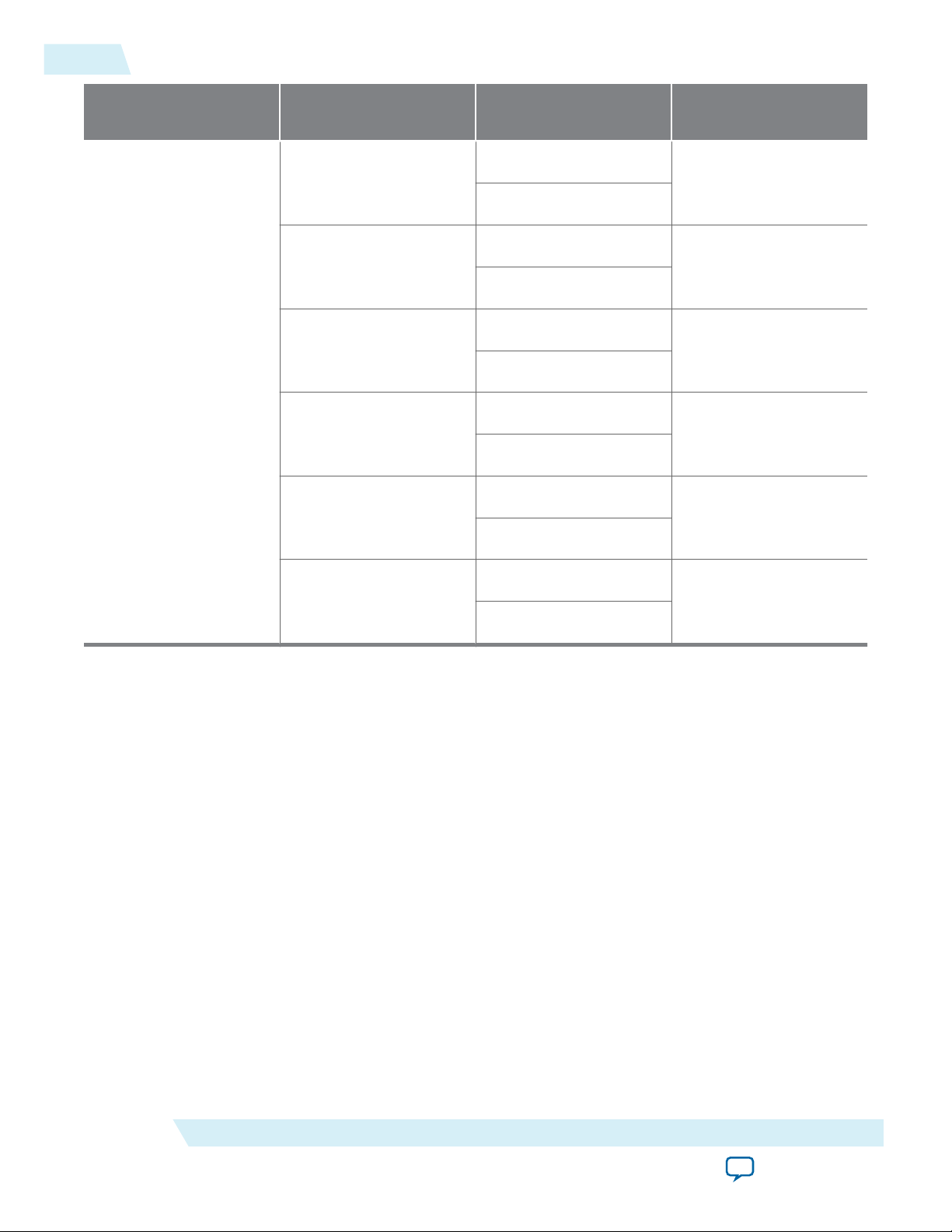
irx_chan[7:0]
irx_num_valid[7:0]
irx_sob[1:0]
irx_eob
irx_sop[1:0]
irx_eopbits[3:0]
irx_dout_words[511:0]
irx_calendar[16 x n - 1:0]
irx_err
itx_chan[7:0]
itx_num_valid[7:0]
itx_sob[1:0]
itx_eob
itx_sop[1:0]
itx_eopbits[3:0]
itx_din_words[511:0]
itx_calendar[16 x n - 1:0]
Transceiver Blocks
TX
PCS
TX
PMA
TX
MAC
TX
Transmit
Buffer
tx_usr_clk
tx_mac_clk
clk_tx_common
clk_rx_common
rx_mac_clk
rx_usr_clk
RX
PCS
RX
PMA
RX
MAC
RX
Regroup
tx_pin[m - 1:0]
rx_pin[m - 1:0]
itx_ready
4-4
High Level Block Diagram
High Level Block Diagram
Figure 4-1: 100G Interlaken Block Diagram
UG-01128
2015.05.04
Clocking and Reset Structure for IP Core
Altera Corporation
The 100G Interlaken MegaCore function consists of two paths: an Interlaken TX path and an Interlaken
RX path. Each path includes MAC, PCS, and PMA blocks. The PCS blocks are implemented in hard IP.
Related Information
• 100G Interlaken IP Core Transmit Path Blocks on page 4-18
For more information about the Interlaken TX path.
• 100G Interlaken IP Core Receive Path Blocks on page 4-27
For more information about the Interlaken RX path.
The following topics describe the clocking and reset structure of the 100G Interlaken IP core:
100G Interlaken IP Core Clock Signals on page 4-5
IP Core Reset on page 4-5
IP Core Reset Sequence with the Reconfiguration Controller on page 4-7
Functional Description
Send Feedback
Page 35

UG-01128
2015.05.04
100G Interlaken IP Core Clock Signals
Table 4-1: 100G Interlaken IP Core Clocks
Clock Name Description
100G Interlaken IP Core Clock Signals
4-5
pll_ref_clk
Reference clock for the RX transceiver PLL in IP
core variations that target an Arria 10 device.
Reference clock for RX and TX transceiver PLLs in
all other variations.
tx_serial_clk[NUM_LANES–1:0]
Clocks for the individual transceiver channels in
100G Interlaken IP core variations that target an
Arria 10 device.
rx_usr_clk
tx_usr_clk
mm_clk
Clock for the receive application interface.
Clock for the transmit application interface.
Management clock for 100G Interlaken IP core
register access.
reconfig_clk
Management clock for Arria 10 hard PCS register
access, including access for Arria 10 transceiver
reconfiguration and testing features.
If you choose to instantiate the optional out-of-band flow control blocks, your 100G Interlaken MegaCore
function has additional clock domains.
Related Information
• Out-of-Band Flow Control Block Clocks on page 10-2
Comprehensive list of out-of-band flow control block clocks and information about their expected
frequencies.
• 100G Interlaken IP Core Clock Interface Signals on page 5-1
Lists the recommended and required frequencies of the 100G Interlaken IP core clocks.
IP Core Reset
The 100G Interlaken IP core variations have a single asynchronous reset, the reset_n signal. The
100G Interlaken IP core manages the initialization sequence internally. After you assert reset_n low, the
IP core automatically goes through the entire reset sequence.
Note:
Altera recommends that you hold the reset_n signal low for at least the duration of two mm_clk
cycles, to ensure the reset sequence proceeds correctly.
Functional Description
Send Feedback
Altera Corporation
Page 36

reset_n
pll_pdn
pll_locked
tx_digital_rst
rx_analog_rst
rx_is_lockedtodata
rx_digital_rst
tx_usr_srst
rx_usr_srst
4-6
IP Core Reset
Figure 4-2: 100G Interlaken IP Core Transceiver Initialization Sequence
The internal initialization sequence implemented by the reset controller included in the 100G Interlaken
IP core. In Arria 10 devices, the pll_locked signal originates in the external PLL. In other devices, it
originates in the 100G Interlaken IP core itself.
UG-01128
2015.05.04
Altera Corporation
Following completion of the reset sequence internally, the 100G Interlaken IP core begins link initializa‐
tion. If your 100G Interlaken IP core and its Interlaken link partner initialize the link successfully, you can
observe the assertion of the lane and link status signals according to the Interlaken specification. For
example, you can monitor the tx_lanes_aligned, sync_locked, word_locked, and rx_lanes_aligned
output status signals.
In Arria V GZ and Stratix V devices, after you assert the reset_n signal, you must wait a certain number
of mm_clk cycles before you can successfully access the 100G Interlaken IP core registers using the IP core
management interface.
• In hardware, you must wait 220 mm_clk cycles.
• In simulation, you must wait 26 mm_clk cycles.
In Arria 10 devices, the required wait time from asserting the reset_n signal to safely accessing the IP
core registers is a function of the internal reset controller.
Related Information
• IP Core Reset Sequence with the Reconfiguration Controller on page 4-7
You must wait until the required Altera Transceiver Reconfiguration Controller completes configura‐
tion of the transceivers before you assert the reset_n signal.
Functional Description
Send Feedback
Page 37

mgmt_clk_locked
mgmt_rst_reset
reconfig_busy
reset_n
(*)
UG-01128
2015.05.04
IP Core Reset Sequence with the Reconfiguration Controller
• Arria 10 Transceiver PHY User Guide
For more information about the Altera reset controller that is included in Arria 10 variations of the
100G Interlaken IP core, refer to the Using the Altera Transceiver PHY Reset Controller section of this
user guide.
IP Core Reset Sequence with the Reconfiguration Controller
If your 100G Interlaken IP core targets an Arria V device or a Stratix V device, you must connect the
100G Interlaken IP core to an Altera Reconfiguration Controller. At power up, the Reconfiguration
Controller configures the transceivers. After power up, upon completion of the transceiver configuration
process, the Reconfiguration Controller returns control of the reset to your application. You must wait
until the Reconfiguration Controller completes configuration of the transceivers before you assert the
reset_n signal.
The Reconfiguration Controller indicates the end of the configuration cycle by deasserting the
reconfig_busy signal. After reconfig_busy is deasserted, you can assert reset_n. Altera recommends
that you hold the reset_n signal low for at least the duration of two mm_clk cycles, to ensure the reset
sequence proceeds correctly.
Figure 4-3: Reset Sequence With the Reconfiguration Controller
Indicates when you can safely assert the reset_n signal of the 100G Interlaken MegaCore IP core.
4-7
Functional Description
You must wait at least 223 mm_clk cycles (or 29 mm_clk cycles in simulation) after the mgmt_clk locks
before you deassert the mgmt_rst_reset input signal to the reconfiguration controller.
Related Information
• Altera Transceiver PHY IP Core User Guide
For more information about the Altera Reconfiguration Controller.
Interleaved and Packet Modes
You can configure the 100G Interlaken IP core to accept interleaved data transfers from the application
on the TX user data transfer interface, or to not accept interleaved data transfers on this interface. If the IP
core can accept interleaved data transfers, it is in Interleaved mode, sometimes also called Segmented
mode. If the IP core does not accept interleaved data transfers, it is in Packet mode. The value you specify
for the Transfer mode selection parameter in the 100G Interlaken parameter editor determines the IP
core transmit mode.
Altera Corporation
Send Feedback
Page 38

4-8
Dual Segment Mode
UG-01128
2015.05.04
In Packet mode, the 100G Interlaken IP Core performs Optional Scheduling Enhancement based on
Section 5.3.2.1.1 of the Interlaken Protocol Specification, Revision 1.2. The IP core ignores the itx_sob and
itx_eob signals. Instead, the IP core performs optional enhanced scheduling based on the settings of
BurstMax, BurstMin, and BurstShort.
In Interleaved mode, the 100G Interlaken IP Core inserts burst control words on the Interlaken link based
on the itx_sob and itx_eob inputs. The internal optional enhanced scheduling is disabled and the
BurstMax and BurstMin values are ignored. BurstShort is still in effect. To avoid overflowing the transmit
FIFO, you should not send a burst that is longer than 1024 bytes.
In Interleaved mode or in Packet mode, the 100G Interlaken IP core is capable of accepting noninterleaved data on the TX user data transfer interface (itx_din_words). However, if the IP core is in
Interleaved mode, the application must drive the itx_sob and itx_eob inputs correctly.
In Interleaved mode or in Packet mode, the 100G Interlaken IP core can generate interleaved data
transfers on the RX user data transfer interface (irx_dout_words). The application must be able to accept
interleaved data transfers if the Interlaken link partner transmits them on the Interlaken link. In this case,
the Interlaken link partner must send traffic in Interleaved mode that conforms with the 100G Interlaken
IP core BurstShort value.
Note: Altera recommends that the transmitter (link partner) only send packets with a minimum packet
size of 64 bytes.
Related Information
• Transfer Mode Selection on page 3-6
• 100G Interlaken IP Core User Data Transfer Interface Signals on page 5-4
• Interlaken Protocol Specification, Revision 1.2
Dual Segment Mode
In dual segment mode, the 100G Interlaken IP core can minimize wasted bandwidth on the user data
transfer interface by starting a packet transfer at Byte 31 (Word 3) of the data bus
(irx_dout_words[511:0]), if the previous packet ended with four or fewer 64-bit words transferred in
the current rx_usr_clk cycle.
In dual segment mode, the IP core is capable of accepting dual segment input on the TX user data transfer
interface (itx_din_words[511:0]). However, the application can control IP core input signals to specify
that the current incoming data transfer does not use dual segment mode. In addition, if you tie the
relevant input signals (itx_sob[0], itx_sop[0], and itx_num_valid[3:0]) permanently low in your
design, the Quartus II Fitter compiles away the IP core logic that generates dual segment output from the
IP core.
Altera Corporation
Functional Description
Send Feedback
Page 39
Word 7 (bits [511:448])
Word 6 (bits [447:384])
Word 5 (bits [383:320])
Word 4 (bits [319:256])
Word 3 (bits [255:192])
Word 2 (bits [191:128])
Word 1 (bits [127:64])
Word 0 (bits [63:0])
Cycle 1 Cycle 2 Cycle 3 Cycle 4 Cycle 5 Cycle 6 Cycle 7
dw8
dw0
dw1
dw2
dw3
dw0
dw1
dw2
dw3
dw4
dw5
dw6
dw7
dw4
dw5
dw6
dw7
dw8
dw9
dw10
dw11
dw12
dw13
dw14
dw15
dw16
dw17
dw18
dw19
dw20
dw21
dw22
dw23
dw0
dw1
dw2
dw3
dw4
dw5
dw6
dw7
dw8
Eight-word data symbol::
UG-01128
2015.05.04
Dual Segment Mode
You must enforce the following additional constraints in sending dual segment traffic to the TX user data
transfer interface:
• The application can start a packet or burst transfer in a single cycle on only one of the most significant
byte (Byte 63) or the middle position (Byte 31) in the 512-bit data symbol. Therefore, the application
can assert only one of itx_sop[1] and itx_sop[0], and only one of itx_sob[1] and itx_sob[0], in
a given cycle. This constraint ensures that the minimum number of idle and data bytes between
consecutive starts of packet or burst is at least 64.
• The application can end a packet or burst transfer only once in a single cycle. Therefore, the minimum
number of idle and data bytes between consecutive ends of packet or burst must be at least 64.
The same constraints apply to dual segment traffic on the RX user data transfer interface: the minimum
number of idle and data bytes between consecutive starts of packet or burst must be at least 64, and the
minimum number of idle and data bytes between consecutive ends of packet or burst must be at least 64.
The 100G Interlaken IP core enforces these constraints on the RX user data transfer interface.
Figure 4-4: Dual Segment Data Transfer
In a dual segment data transfer, the end of one data burst and the start of another can appear in the same
clock cycle. In this example, each column represents a single 512-bit data symbol, divided into 64-bit
words, and each color represents a separate data burst. The second and third data bursts are dual segment
transfers.
4-9
Functional Description
Send Feedback
Related Information
• Data Format on page 3-6
• 100G Interlaken IP Core User Data Transfer Interface Signals on page 5-4
• 100G Interlaken IP Core Dual Segment Interleaved Data Transfer Transmit Example on page 415
Example of dual segment data transfers on the TX user data transfer interface.
• 100G Interlaken IP Core Dual Segment Interleaved Data Transfer Receive Example on page 4-22
Example of dual segment data transfers on the RX user data transfer interface.
Altera Corporation
Page 40

4-10
M20K ECC Support
M20K ECC Support
If you turn on Enable M20K ECC support in your Stratix V or Arria 10 100G Interlaken IP core
variation, the IP core takes advantage of the built-in device support for ECC checking in all M20K blocks
configured in the IP core on the device. The feature performs single-error correct, double-adjacent-error
correct, and triple-adjacent-error detect ECC functionality in the M20K memory blocks configured in
your IP core. The IP core reports ECC error statistics in the registers CNT_ERR_TX, CNT_UNCOR_TX,
CNT_ERR_RX, and CNT_UNCOR_RX at offsets 0x122 through 0x125.
This feature enhances data reliability but increases latency and resource utilization. Without the ECC
feature, a single M20K memory block can support a data path width of 40 bits. With the ECC feature,
eight of those bits are dedicated to the ECC, and an M20K memory block can support a maximum data
path width of 32 bits. Therefore, when M20K ECCsupport is turned on the IP core configures additional
M20K memory blocks. The ECC check adds latency to the path through the memory block, and increases
the amount of device memory used by your IP core.
Related Information
• Enable M20K ECC Support on page 3-4
• 100G Interlaken IP Core Register Map on page 6-1
Describes the CNT_ERR_TX, CNT_UNCOR_TX, CNT_ERR_RX, and CNT_UNCOR_RX 100G Interlaken IP core
M20K ECC status registers.
• Embedded Memory Blocks in Stratix V Devices
Information about the built-in ECC feature in Stratix V devices.
• Embedded Memory Blocks in Arria 10 Devices
Information about the built-in ECC feature in Arria 10 devices.
UG-01128
2015.05.04
100G Interlaken IP Core Transmit Path
The 100G Interlaken MegaCore function accepts application data from up to 256 channels and combines
it into a single data stream in which data is labeled with its source channel. The 100G Interlaken TX MAC
and PCS blocks format the data into protocol-compliant bursts and insert Idle words where required.
100G Interlaken IP Core Transmit User Data Interface Examples
The following examples illustrate how to use the Altera 100G Interlaken IP core TX user data interface:
100G Interlaken IP Core Interleaved Mode (Segmented Mode) Example on page 4-10
100G Interlaken IP Core Packet Mode Operation Example on page 4-12
100G Interlaken IP Core Back-Pressured Packet Transfer Example on page 4-13
100G Interlaken IP Core Dual Segment Interleaved Data Transfer Transmit Example on page 4-15
100G Interlaken IP Core Interleaved Mode (Segmented Mode) Example
In Interleaved Mode, you are responsible for scheduling the burst. You need to drive an extra pair of
signals, Start of Burst (SOB) and End of Burst (EOB), to indicate the burst boundary. You can send the
traffic in packet order or interleaved order, as long as you set the SOB and EOB flags correctly to establish
the data boundaries.
Altera Corporation
Functional Description
Send Feedback
Page 41
tx_usr_clk
itx_sop[1]
itx_chan
itx_sob[1]
itx_eob
itx_din_words
itx_num_valid[7:4]
itx_eopbits
Cycle 1 Cycle 2 Cycle 3 Cycle 4 Cycle 5 Cycle 6 Cycle 7 Cycle 8 Cycle 9
8’h2
d1
d2
d3
4’b1000
4’b1000
4’b0011
4’b0000
d4
4’b0000 4’b1000
8’h4
8’h2 8’h3
8’h4
d5
d6
d7
4’b1000
4’b1000
4’b0010
4’b1011
4’b1011
4’b0000 4’b0000 4’b0000 4’b0000
UG-01128
2015.05.04
100G Interlaken IP Core Interleaved Mode (Segmented Mode) Example
Figure 4-5: Packet Transfer on Transmit Interface in Interleaved Single Segment Mode
This example illustrates the expected behavior of the 100G Interlaken IP core application interface
transmit signals during data transfers from the application to the IP core on the TX user data transfer
interface in interleaved, single segment mode.
4-11
The figure shows the timing diagram for an interleaved data transfer in Interleaved mode. In cycle 1, the
application asserts itx_sop[1] and itx_sob[1], indicating that this cycle is both the start of the burst
and the start of the packet. The value the application drives on itx_chan indicates the data originates
from channel 2.
In cycle 2, the application asserts itx_eob, indicating the data the application transfers to the IP core in
this clock cycle is the end of the burst. (itx_chan only needs to be valid when itx_sob[1] or itx_sop[1]
is asserted). itx_num_valid[7:4] indicates all eight words are valid. However, the data in this cycle is not
end of packet data. The application is expected to transfer at least one additional data burst in this packet,
possibly interleaved with one or more bursts in packets from different data channels.
Cycle 3 is a short burst with both itx_sob[1] and itx_eob asserted. The application drives the value of
three on itx_num_valid[7:4] to indicate that three words of the eight-word itx_din_words data bus are
valid. The data is packed in the most significant words of itx_din_words.The application drives the value
of 4'b1011 on itx_eopbits to indicate that the data the application transfers to the IP core in this cycle
are the final words of the packet, and that in the final word of the packet, only three bytes are valid data.
The value the application drives on itx_chan indicates this burst originates from channel 4.
In cycle 4, the itx_num_valid[7:4] signal has the value of zero, which means this cycle is an idle cycle.
In cycle 5, the application sends another single-cycle data burst from channel 2, by assertingitx_sob[1]
and itx_eob to indicate this data is both the start and end of the burst. The application does not assert
itx_sop[1], because this burst is not start of packet data. itx_eopbits has the value of 4'b0000,
indicating this burst is also not end of packet data. This data follows the data burst transfered in cycles 1
and 2, within the same packet from channel 2.
In cycle 6, the application sends a start of packet, single-cycle data burst from channel 3.
In cycles 7 and 8, the application sends a two-cycle data packet in one two-cycle burst. In cycle 8, the
second data cycle, the application drives the value of two on itx_num_valid[7:4] and the value of
4'b1011 on itx_eopbits, to tell the IP core that in this clock cycle, the two most significant words of the
Functional Description
Send Feedback
Altera Corporation
Page 42
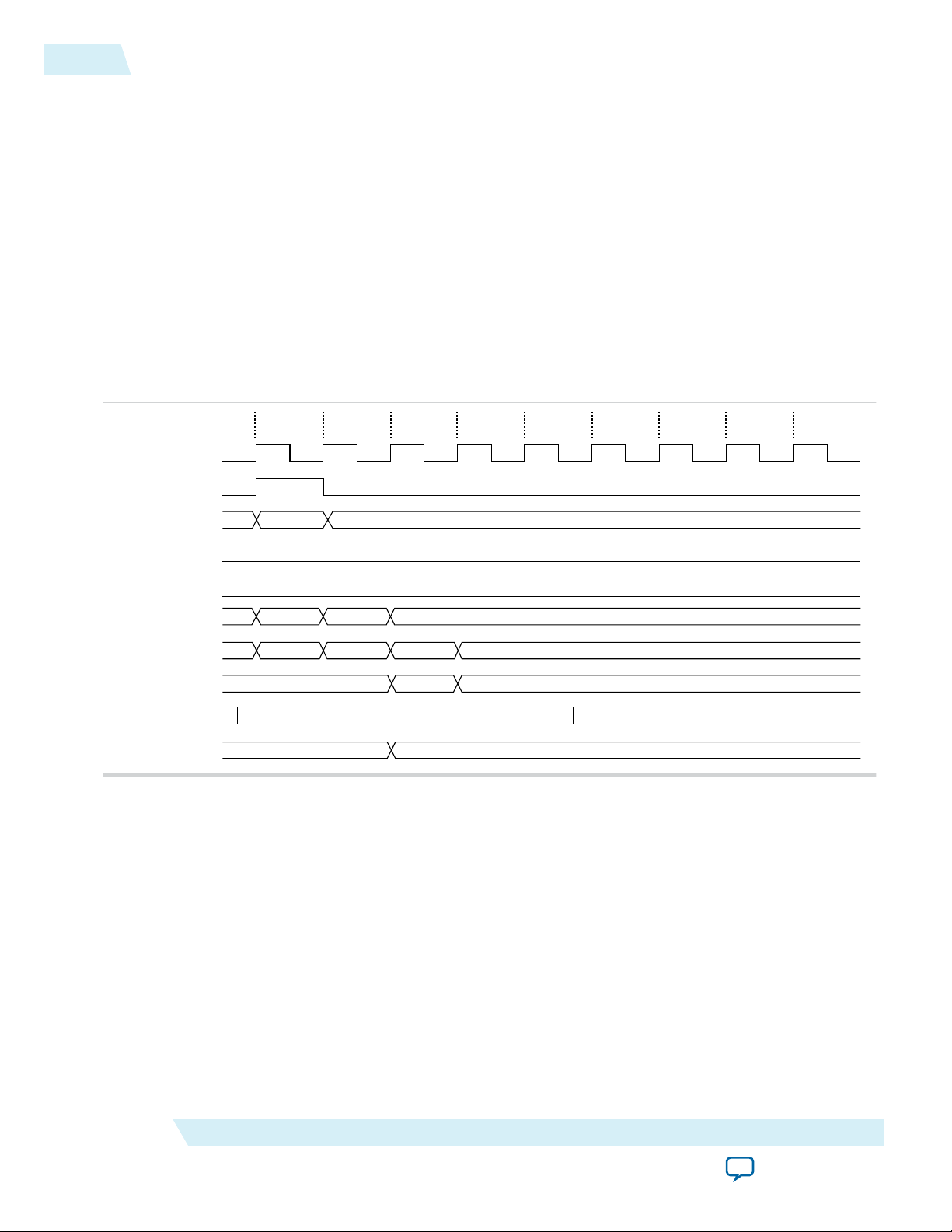
tx_usr_clk
itx_sop[1]
itx_chan
itx_sob[1]
itx_eob
itx_din_words
itx_num_valid[7:4]
itx_eopbits
itx_ready
itx_calendar
Cycle 1 Cycle 2 Cycle 3 Cycle 4 Cycle 5 Cycle 6 Cycle 7 Cycle 8 Cycle 9
8’h2
d1
d2
d3
4’b1000
4’b1000
4’b0111
4’b0000
4’b1011
64’hffff_ffff_ffff_ffff 64’h1111_2222_3333_4444
4-12
100G Interlaken IP Core Packet Mode Operation Example
data symbol contain valid data and the remaining words do not contain valid data, and that in the second
of these two words, only the three most significant bytes contain valid data.
In Interleaved Mode, you can transfer a packet without interleaving as long as the channel number does
not toggle during the same packet transfer. However, you must still assert the itx_sob and itx_eob
signals correctly to maintain the proper burst boundaries.
If you do not drive the itx_sob and itx_eob signals, the 100G Interlaken IP Core does not operate
properly and the transmit FIFO may overflow, since in this mode the internal logic is looking for itx_sob
and itx_eob assertion for insertion of proper burst control words.
100G Interlaken IP Core Packet Mode Operation Example
Figure 4-6: Packet Transfer on Transmit Interface in Packet Mode
This example illustrates the expected behavior of the 100G Interlaken IP core application interface
transmit signals during a packet transfer in single segment packet mode.
UG-01128
2015.05.04
Altera Corporation
The figure illustrates a packet mode data transfer of 179 bytes on the transmit interface into the IP core. In
this mode, the 100G Interlaken IP core ignores the itx_sob and itx_eob input signals.
To start a transfer, you assert itx_sop[1] when you have data ready on itx_din_words. At the following
rising edge of the clock, the IP core detects that itx_sop[1] is asserted, indicating that the value on
itx_din_words in the current cycle is the start of an incoming data packet. When you assert itx_sop[1],
you must also assert the correct value on itx_chan to tell the IP core the data channel source of the data.
In this example, the value 2 on itx_chan tells the IP core that the data originates from channel number 2.
Functional Description
Send Feedback
Page 43
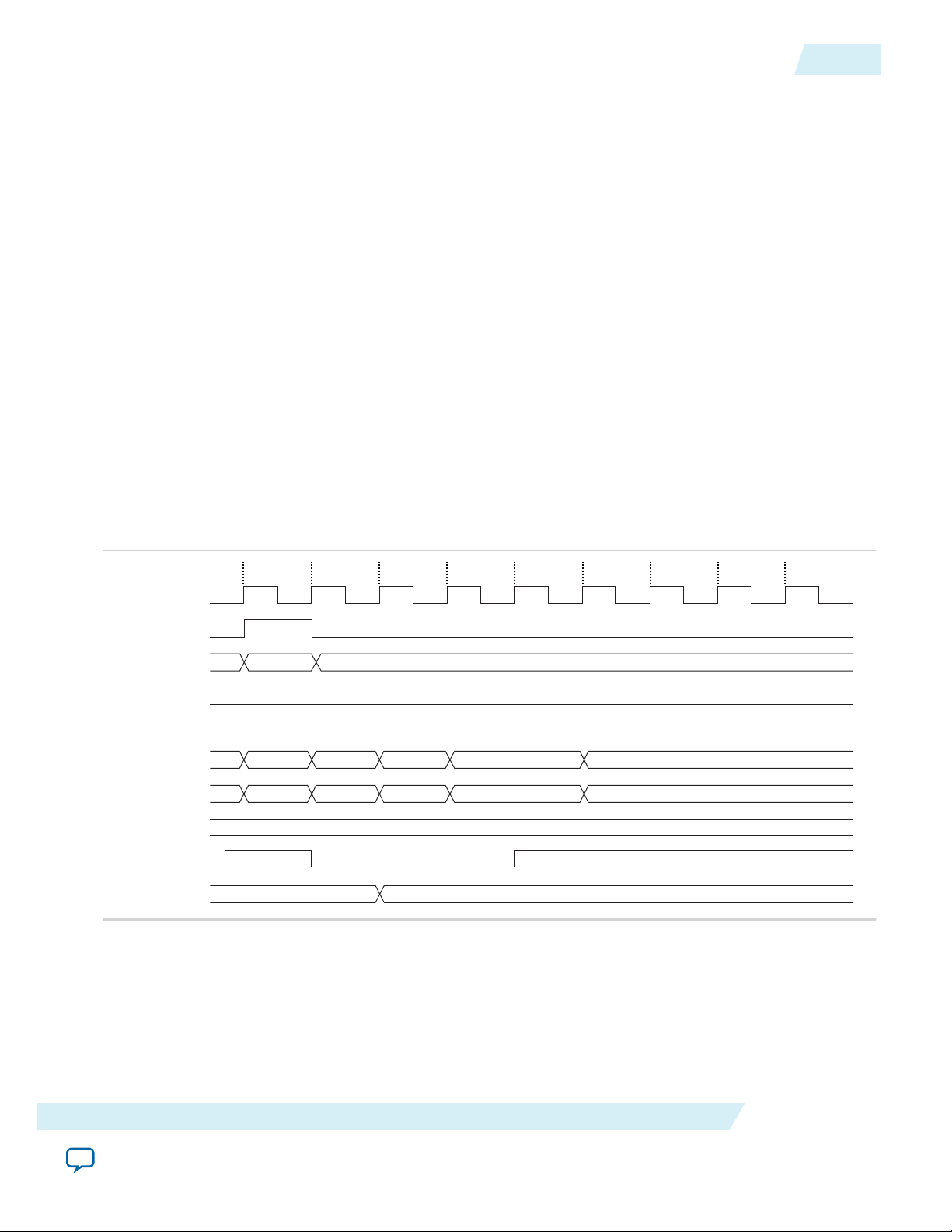
tx_usr_clk
itx_sop[1]
itx_chan
itx_sob[1]
itx_eob
itx_din_words
itx_num_valid[7:4]
itx_eopbits
itx_ready
itx_calendar
Cycle 1 Cycle 2 Cycle 3 Cycle 4 Cycle 5 Cycle 6 Cycle 7 Cycle 8 Cycle 9
8’h2
d1
d2 d3
4’b1000
4’b1000
4’b1000
4’b0000
d4
4’b0000
4’b1000
64’hffff_ffff_ffff_ffff 64’h1111_2222_3333_4444
UG-01128
2015.05.04
100G Interlaken IP Core Back-Pressured Packet Transfer Example
During the SOP cycle (labeled with data value d1) and the cycle that follows the SOP cycle (labeled with
data value d2), you must hold the value of itx_num_valid[7:4] at 4'b1000. In the following clock cycle,
labeled with data value d3, you must hold the following values on critical input signals to the IP core:
• itx_num_valid[7:4] at the value of 4'b0111 to indicate the current data symbol contains seven 64-bit
words of valid data.
• itx_eopbits[3] high to indicate the current cycle is an EOP cycle.
• itx_eopbits[2:0] at the value of 3'b011 to indicate that only three bytes of the final valid data word
are valid data bytes.
This signal behavior correctly transfers a data packet with the total packet length of 179 bytes to the IP
core, as follows:
• In the SOP cycle, the IP core receives 64 bytes of valid data (d1).
• In the following clock cycle, the IP core receives another 64 bytes of valid data (d2).
• In the third clock cycle, the EOP cycle, the IP core receives six full words (6 x 8 = 48 bytes) and three
bytes of valid data, for a total of 51 valid bytes.
The total packet length is 64 + 64 + 51 = 179 bytes.
100G Interlaken IP Core Back-Pressured Packet Transfer Example
Figure 4-7: Packet Transfer on Transmit Interface with Back Pressure
4-13
This example illustrates the expected behavior of the 100G Interlaken application interface transmit
signals during a packet transfer with back pressure.
In this example, the 100G Interlaken IP Core accepts the first four data symbols (256 bytes) of a data
packet. The clock cycles in which the application transfers the data values d2 and d3 to the
100G Interlaken IP Core are grace-period cycles following the 100G Interlaken IP Core's de-assertion of
itx_ready.
The 100G Interlaken IP Core supports up to 4 cycles of grace period, enabling you to register the input
data and control signals, as well as the itx_ready signal, without changing functionality. The grace period
Functional Description
Send Feedback
Altera Corporation
Page 44

4-14
100G Interlaken IP Core Back-Pressured Packet Transfer Example
UG-01128
2015.05.04
supports your design in achieving timing closure more easily. In any case you must ensure that you hold
itx_num_valid at the value of 0 when you are not driving data.
You can think of this interface as a FIFO write interface. When itx_num_valid[7:4] is nonzero, both
data and control information (including itx_num_valid[7:4] itself) are written to the transmit side data
interface. The itx_ready signal is the inverse of a hypothetical FIFO-almost-full flag. When itx_ready is
high, the 100G Interlaken IP Core is ready to accept data. When itx_ready is low, you can continue to
send data for another 6 to 8 clock cycles of tx_usr_clk.
Related Information
100G Interlaken IP Core In-Band Calendar Bits on Transmit Side on page 4-17
Description of in-band calendar bits on the TX user data transfer interface.
Altera Corporation
Functional Description
Send Feedback
Page 45

tx_usr_clk
itx_sop[1]
itx_chan
itx_sob[1]
itx_eob
itx_din_words
Word 7
Word 6
Word 5
Word 4
Word 3
Word 2
Word 1
Word 0
itx_num_valid[7:4]
itx_eopbits
Cycle 1 Cycle 2 Cycle 3 Cycle 4 Cycle 5 Cycle 6 Cycle 7
8’h2
d1
d2
d3
4’b1000
4’b0001
4’b1000
d4
4’b1000 4’b0101
itx_sop[0]
itx_sob[0]
8’h3
8’h2
d5 d6
4’b0100
itx_num_valid[3:0]
4’b0000
4’b0100
4’b0000
4’b0100 4’b0000
4’b0000 4’b0000 4’b1000 4’b1000
4’b0000
dw8
dw0
dw1
dw2
dw3
dw0
dw1
dw2
dw3
dw4
dw5
dw6
dw7
dw4
dw5
dw6
dw7
dw8
dw9
dw10
dw11
dw12
dw13
dw14
dw15
dw16
dw17
dw18
dw19
dw20
dw21
dw22
dw23
dw0
dw1
dw2
dw3
dw4
dw5
dw6
dw7
dw8
itx_din_words:
UG-01128
2015.05.04
100G Interlaken IP Core Dual Segment Interleaved Data Transfer Transmit Example
100G Interlaken IP Core Dual Segment Interleaved Data Transfer Transmit Example
Figure 4-8: Dual Segment Data Transfer on Transmit Interface in Interleaved Mode
This example illustrates the expected behavior of the 100G Interlaken IP core application interface
transmit signals during dual segment transfers of three data bursts in interleaved mode.
4-15
Functional Description
The figure shows three data bursts in dual segment mode on the TX user data transfer interface. In cycle
1, the application asserts itx_sop[1] and itx_sob[1], indicating that this cycle is both the start of the
burst and the start of the packet, and that data starts from the most significant byte of the data symbol.
The application drives the value of 2 on itx_chan to indicate the data originates from channel 2.
Send Feedback
Altera Corporation
Page 46

4-16
100G Interlaken IP Core Dual Segment Interleaved Data Transfer Transmit Example
UG-01128
2015.05.04
In cycle 2, the following two events occur:
• The first data burst completes. The application asserts itx_eob, indicating the data the application
transfers to the IP core in this clock cycle is the end of the burst. The value the application drives on
itx_num_valid[7:4] indicates that one word in this data symbol is valid data associated with this
burst. In addition, the application drives itx_eopbits to the value of 4'b0000 to indicate that the data
the application transfers to the IP core in this clock cycle is not the end of the packet. Therefore, all
bytes in this data word are valid.
• A second data burst starts at Word 3. This transfer is a dual segment transfer, as is allowed whether or
not the IP core is configured in dual segment mode on the RX side. The application asserts
itx_sop[0] and itx_sob[0], indicating that this cycle is both the start of the burst and the start of the
packet, and that data in this burst and packet starts from Byte 31 of the data symbol. The application
drives the value of 3 on itx_chan to indicate the data originates from channel 3. The value of
itx_num_valid[3:0] is 4'b0100, indicating this data transfer is a dual segment data transfer—that it
begins at Word 3. The value of itx_num_valid[7:4] has no relevance for the data words in this burst
that appear in this data symbol, except to indicate the previous burst includes no data in these words of
the data symbol (Words 3 through 0), and therefore, that they are available for the second data burst.
As is required, the dual segment data transfer places valid data in all four words in the least significant
half of the data symbol.
In cycles 3 and 4, the second data burst continues with no EOB or EOP indication. The IP core does not
sample the value of itx_chan in these clock cycles, and its value is therefore a Don't Care. The value on
itx_num_valid[7:4] indicates that all eight words in each of these data symbols are valid data associated
with this burst.
In cycle 5, the following two events occur:
• The second data burst completes. The application asserts itx_eob, indicating the data transfered in
this clock cycle is the end of the burst. The value the application drives on itx_num_valid[7:4]
indicates that four words in this data symbol are valid data associated with this burst. In addition, the
value the application drives on itx_eopbits indicates the data is the end of the packet, and that all
eight bytes of the final data word are valid data bytes.
• A third data burst starts at Word 3. This transfer is a dual segment transfer, as is allowed whether or
not the IP core is configured in dual segment mode on the RX side. The application asserts
itx_sob[0], indicating that this cycle is the start of the burst and that data in this burst starts from
Byte 31 of the data symbol. However, the application does not assert itx_sop[0], indicating this burst
is not the first burst in the packet. The value the application drives on itx_chan indicates the data
originates from channel 2. Therefore, we can conclude this data burst is the second burst in a packet
from channel 2. The value the application drives on itx_num_valid[3:0] is 4'b0100, indicating this
data transfer is a dual segment data transfer—that it begins at Word 3. The value of
itx_num_valid[7:4] has no relevance for the data words in this burst that appear in this data symbol,
except to indicate the previous burst includes no data in these words of the data symbol (Words 3
through 0), and therefore, that they are available for the second data burst. As is required, the dual
segment data transfer places valid data in all four words in the least significant half of the data symbol.
In cycle 6, the third data burst completes. The application asserts itx_eob, indicating the data transfered
in this clock cycle is the end of the burst. The value on itx_num_valid[7:4] indicates that five words in
this data symbol are valid data associated with this burst. In addition, the value the application drives on
itx_eopbits indicates the data is the end of the packet, and that all eight bytes of the final data word are
valid data bytes. Because the data from this burst occupies words 7 through 3 of the data symbol, another
burst cannot start in the current data symbol.
Altera Corporation
Functional Description
Send Feedback
Page 47

UG-01128
2015.05.04
100G Interlaken IP Core In-Band Calendar Bits on Transmit Side
In dual segment mode as in single segment mode, if the IP core is in Interleaved mode, you can transfer a
packet without interleaving—if you do not toggle the channel number during the packet transfer, the
packet is not interleaved with another packet. However, you must still assert the itx_sob and itx_eob
signals correctly to maintain the proper burst boundaries.
If you do not drive the itx_sob and itx_eob signals, the 100G Interlaken IP Core does not operate
properly and the transmit FIFO may overflow, since in this mode the internal logic is looking for itx_sob
and itx_eob assertion for insertion of proper burst control words.
Related Information
Dual Segment Mode on page 4-8
100G Interlaken IP Core In-Band Calendar Bits on Transmit Side
If you turn on Include in-band flow control functionality, the itx_calendar input signal supports inband flow control. It is synchronous with tx_usr_clk, but does not align with the packets on the user
data interface. The 100G Interlaken IP Core reads the itx_calendar bits and encodes them in control
words (Burst control words and Idle control words) opportunistically.
If you hold all the calendar bits at one, you indicate an XON setting for each channel. You should set the
calendar bits to 1 to indicate that the Interlaken link partner does not need to throttle the data it transfers
to this 100G Interlaken IP Core. Set this value by default if you choose not to use the in-band flow control
feature of the 100G Interlaken IP Core. If you decide to turn off any channel, you must drive the
corresponding bits of itx_calendar with zero (the XOFF setting) for that channel.
4-17
If you turn on Include in-band flow control functionality, the100G Interlaken IP Core transmits each
page of the itx_calendar bits on the Interlaken link in a separate control word, starting with the most
significant page and working through the pages, in order, to the least significant page. If you turn off
Include in-band flow control functionality, the IP core fills each flow control bit in each control word
with the value of 1.
Consider an example where the number of calendar pages is four and itx_calendar bits are set to the value
64'h1111_2222_3333_4444. In this example, the Number of calendar pages parameter is set to four, and
therefore the width of the itx_calendar signal is 4 x 16 = 64 bits. Each of these bits is a calendar bit. The
transmission begins with the page with the value of 16'h1111 and works through the pages in order until
the least significant page with the value of 16'h4444.
In this example, four control words are required to send the full set of 64 calendar bits from the
itx_calendar signal. The 100G Interlaken IP Core automatically sets the Reset Calendar bit[56] of the
next available control word to the value of one, to indicate the start of transmission of a new set of
calendar pages, and copies the most significant page (16'h1111 in this example) to the In-Band Flow
Control bits[55:40] of the control word. It maps the most significant bit of the page to the control word
bit[55] and the least significant bit of the page to the control word bit[40].
The table shows the value of the Reset Calendar bit and the In-Band Flow Control bits in the four
Interlaken link control words that transmit the 64'h1111_2222_3333_4444 value of itx_calendar:
Table 4-2: Value of Reset Calendar Bit and In-band Flow Control Bits in the Example
Control Word Reset Calendar Bit (bit [56]) In-Band Flow Control Bits (bits [55:40])
First 1 16'b0001000100010001 (16'h1111)
Functional Description
Send Feedback
Altera Corporation
Page 48
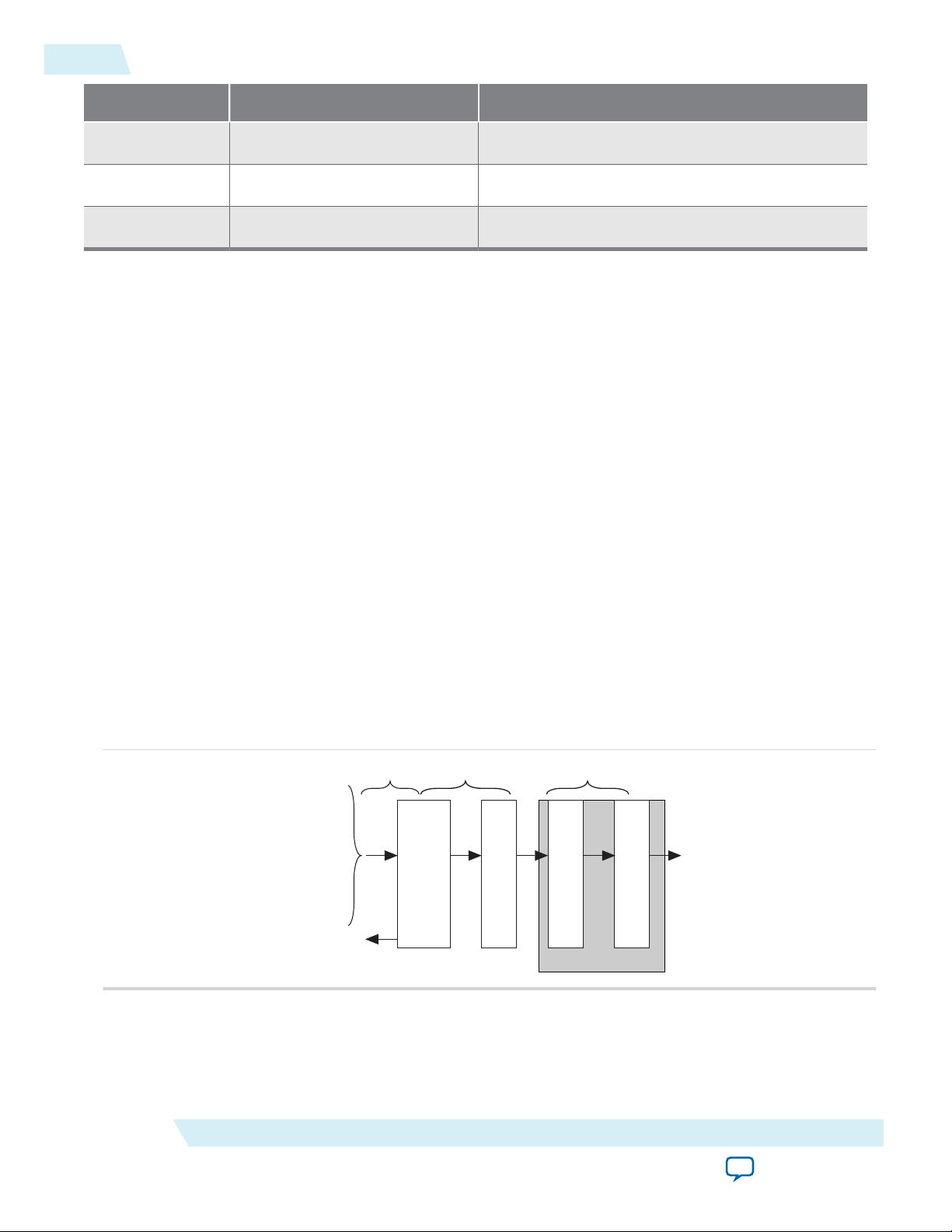
itx_chan[7:0]
itx_num_valid[7:0]
itx_sob[1:0]
itx_eob
itx_sop[1:0]
itx_eopbits[3:0]
itx_din_words[511:0]
itx_calendar[16 x n - 1:0]
Transceiver Blocks
TX
PCS
TX
PMA
TX
MAC
TX
Transmit
Buffer
tx_usr_clk
tx_mac_clk
clk_tx_common
tx_pin[m - 1:0]
itx_ready
4-18
100G Interlaken IP Core Transmit Path Blocks
Control Word Reset Calendar Bit (bit [56]) In-Band Flow Control Bits (bits [55:40])
Second 0 16'b0010001000100010 (16'h2222)
Third 0 16'b0011001100110011 (16'h3333)
Fourth 0 16'b0100010001000100 (16'h4444)
For details of the control word format, refer to the Interlaken Protocol Specification, Revision 1.2.
The 100G Interlaken IP Core supports itx_calendar widths of 1, 2, 4, 8, and 16 16-bit calendar pages.
You configure the width in the 100G Interlaken IP Core parameter editor.
By convention, in a standard case, each calendar bit corresponds to a single data channel. However, the
100G Interlaken IP Core assumes no default usage. You must map the calendar bits to channels or link
status according to your specific application needs. For example, if your design has 64 physical channels,
but only 16 priority groups, you can use a single calendar page and map each calendar bit to four physical
channels. As another example, for a different application, you can use additional calendar bits to pass
quality-of-service related information to the Interlaken link partner.
If your application flow-controls a channel, you are responsible for dropping the relevant packet. Altera
supports the transfer of the itx_calendar values you provide without examining the data that is affected
by in-band flow control of the Interlaken link.
UG-01128
2015.05.04
Related Information
• 100G Interlaken IP Core Back-Pressured Packet Transfer Example on page 4-13
Example of in-band calendar bits usage on the TX user data transfer interface.
• Interlaken Protocol Specification, Revision 1.2
100G Interlaken IP Core Transmit Path Blocks
Figure 4-9: 100G Interlaken IP Core Transmit Path
Altera Corporation
The 100G Interlaken IP core transmit data path has the following four main functional blocks:
100G Interlaken IP Core TX Transmit Buffer on page 4-19
Functional Description
Send Feedback
Page 49

UG-01128
2015.05.04
100G Interlaken IP Core TX MAC on page 4-19
100G Interlaken IP Core TX PCS on page 4-19
100G Interlaken IP Core TX PMA on page 4-19
100G Interlaken IP Core TX Transmit Buffer
The 100G Interlaken MegaCore function TX transmit buffer performs the following functions:
• Aligns the incoming user application data, itx_data, in the IP core internal format.
• Implements domain crossing from the tx_usr_clk clock domain to the tx_mac_clk clock domain.
100G Interlaken IP Core TX MAC
The 100G Interlaken MegaCore function TX MAC performs the following functions:
• Inserts burst and idle control words in the incoming data stream. Burst delineation allows packet
segmentation in the Interlaken protocol.
• Performs flow adaption of the data stream, repacking the data to ensure the maximum number of
words is available on each valid clock cycle.
• Calculates and inserts CRC24 bits in all burst and idle words.
• Inserts calendar data in all burst and idle words, if you configure in-band flow control.
• Stripes the data across the PCS lanes. Configurable order, default is MSB of the data goes to lane 0.
• Buffers data between the application and the TX PCS block in the TX FIFO buffer. The TX PCS block
uses the FIFO buffer to recover bandwidth when the number of words delivered to the transmitter is
less than the full width.
100G Interlaken IP Core TX Transmit Buffer
4-19
100G Interlaken IP Core TX PCS
TX PCS logic is an embedded hard macro and does not consume FPGA soft logic elements.
The 100G Interlaken MegaCore function TX PCS block performs the following functions for each lane:
• Inserts the meta frame words in the incoming data stream.
• Calculates and inserts the CRC32 bits in the meta frame diagnostic words.
• Scrambles the data according to the scrambler seed and the protocol-specified polynomial.
• Performs 64B/67B encoding.
100G Interlaken IP Core TX PMA
The 100G Interlaken MegaCore function TX PMA serializes the data and sends it out on the Interlaken
link.
100G Interlaken IP Core Receive Path
The 100G Interlaken MegaCore function receives data on the Interlaken link, monitors and removes
Interlaken overhead, and provides user data and calendar information to the application.
Calendar information is available only if you turn on Include in-band flow control block in the
100G Interlaken parameter editor.
Functional Description
Send Feedback
Altera Corporation
Page 50

Cycle 1 Cycle 2 Cycle 3 Cycle 4 Cycle 5 Cycle 6 Cycle 7 Cycle 8 Cycle 9
rx_usr_clk
irx_sop[1]
irx_sob[1]
irx_eob
irx_dout_words d1
4’b1000 4’b1000 4’b0011 4’b00104’b10004’b0000
4’b0000 4’b0000 4’b0000 4’b00004’b1011 4’b10114’b0000
4’b1000 4’b1000
d2 d3 d4 d5 d6 d7
irx_num_valid[7:4]
irx_eopbits
irx_chan 8’h2 8’h4 8’h48’h38’h2
4-20
100G Interlaken IP Core Receive User Data Interface Examples
100G Interlaken IP Core Receive User Data Interface Examples
The following examples illustrate how to use the Altera 100G Interlaken IP core RX user data interface:
100G Interlaken IP Core Receiver Side Example on page 4-20
100G Interlaken IP Core Dual Segment Interleaved Data Transfer Receive Example on page 4-22
100G Interlaken IP Core Receiver Side Example
The 100G Interlaken IP Core can generate interleaved data transfers on the RX user data transfer
interface. The IP core always toggles the irx_sob and irx_eob signals to indicate the beginning of the
burst and end of the burst. In single segment mode, only irx_sob[1] toggles. In dual segment mode,
irx_sob[0] toggles if the current burst starts at word 4 of the data symbol.
Figure 4-10: 100G Interlaken IP Core Receiver Side Single Segment Example
This example illustrates the expected behavior of the 100G Interlaken IP core application interface receive
signals during data transfers from the IP core to the application on the RX user data transfer interface in
interleaved, single segment mode.
UG-01128
2015.05.04
The figure shows the timing diagram for an interleaved data transfer in Interleaved mode. In cycle 1, the
IP core asserts irx_sop[1] and irx_sob[1], indicating that this cycle is both the start of the burst and the
start of the packet. The first word is MSB aligned at the top. The value the IP core drives on irx_chan
indicates the data targets channel 2. You must sample irx_chan during cycles in which irx_sob[1] is
asserted. The irx_chan output signal is not guaranteed to remain valid for the duration of the burst.
In cycle 2, the IP core asserts irx_eob, indicating the data the IP core transfers to the application in this
clock cycle is the end of the burst. irx_num_valid[7:4] indicates all eight words are valid. However, the
data in this cycle is not end of packet data. The IP core will transfer at least one additional data burst in
this packet, possibly interleaved with one or more bursts in packets that target different data channels.
Cycle 3 is a short burst with both irx_sob[1] and irx_eob asserted. The IP core drives the value of three
on irx_num_valid[7:4] to indicate that three words of the eight-word irx_dout_words data bus are
valid. The data is packed in the most significant words of irx_dout_words.The IP core drives the value of
Altera Corporation
Functional Description
Send Feedback
Page 51

UG-01128
2015.05.04
100G Interlaken IP Core Receiver Side Example
4-21
4'b1011 on irx_eopbits to indicate that the data the IP core transfers to the application in this cycle are
the final words of the packet, and that in the final word of the packet, only three bytes are valid data. The
value the IP core drives on irx_chan indicates this burst targets channel 4.
In cycle 4, the irx_num_valid[7:4] signal has the value of zero, which means this cycle is an idle cycle.
In cycle 5, the IP core sends another single-cycle data burst to channel 2, by assertingirx_sob[1] and
irx_eob to indicate this data is both the start and end of the burst. The IP core does not assert
irx_sop[1], because this burst is not start of packet data. irx_eopbits has the value of 4'b0000,
indicating this burst is also not end of packet data. This data follows the data burst transfered in cycles 1
and 2, within the same packet the IP core is sending to channel 2.
In cycle 6, the IP core sends a start of packet, single-cycle data burst to channel 3.
In cycles 7 and 8, the IP core sends a two-cycle data packet in one two-cycle burst. In cycle 8, the second
data cycle, the IP core drives the value of two on irx_num_valid[7:4] and the value of 4'b1011 on
irx_eopbits, to tell the application that in this clock cycle, the two most significant words of the data
symbol contain valid data and the remaining words do not contain valid data, and that in the second of
these two words, only the three most significant bytes contain valid data.
Functional Description
Send Feedback
Altera Corporation
Page 52

rx_usr_clk
irx_sop[1]
irx_chan
irx_sob[1]
irx_eob
irx_dout_words
Word 7
Word 6
Word 5
Word 4
Word 3
Word 2
Word 1
Word 0
irx_num_valid[7:4]
irx_eopbits
Cycle 1 Cycle 2 Cycle 3 Cycle 4 Cycle 5 Cycle 6 Cycle 7
8’h2
d1
d2
d3
4’b1000
4’b0001
4’b1000
d4
4’b1000 4’b0101
irx_sop[0]
irx_sob[0]
8’h3
8’h2
d5 d6
4’b0100
irx_num_valid[3:0]
4’b0000
4’b0100
4’b0000
4’b0100 4’b0000
4’b0000 4’b0000 4’b1000 4’b1000
4’b0000
dw8
dw0
dw1
dw2
dw3
dw0
dw1
dw2
dw3
dw4
dw5
dw6
dw7
dw4
dw5
dw6
dw7
dw8
dw9
dw10
dw11
dw12
dw13
dw14
dw15
dw16
dw17
dw18
dw19
dw20
dw21
dw22
dw23
dw0
dw1
dw2
dw3
dw4
dw5
dw6
dw7
dw8
irx_dout_words:
4-22
100G Interlaken IP Core Dual Segment Interleaved Data Transfer Receive Example
100G Interlaken IP Core Dual Segment Interleaved Data Transfer Receive Example
Figure 4-11: Dual Segment Data Transfer on Receive Interface in Interleaved Mode
This example illustrates the expected behavior of the 100G Interlaken IP core application interface receive
signals during dual segment transfers of three data bursts in interleaved mode. The 100G Interlaken IP
core can generate dual segment data transfers only if you configure the IP core in dual segment mode.
UG-01128
2015.05.04
Altera Corporation
The figure shows three data bursts in dual segment mode on the RX user data transfer interface. In cycle
1, the IP core asserts irx_sop[1] and irx_sob[1], indicating that this cycle is both the start of the burst
and the start of the packet, and that data starts from the most significant byte of the data symbol. The IP
core drives the value of 2 on irx_chan to indicate the data targets channel 2.
Functional Description
Send Feedback
Page 53

UG-01128
2015.05.04
100G Interlaken IP Core Dual Segment Interleaved Data Transfer Receive Example
4-23
In cycle 2, the following two events occur:
• The first data burst completes. The IP core asserts irx_eob, indicating the data the IP core transfers to
the application in this clock cycle is the end of the burst. The value the IP core drives on
irx_num_valid[7:4] indicates that one word in this data symbol is valid data associated with this
burst. In addition, the IP core drives irx_eopbits to the value of 4'b0000 to indicate that the data the
IP core transfers to the application in this clock cycle is not the end of the packet.
• A second data burst starts at Word 3, as is allowed in dual segment mode. The IP core asserts
irx_sop[0] and irx_sob[0], indicating that this cycle is both the start of the burst and the start of the
packet, and that data in this burst and packet starts from Byte 31 of the data symbol. The IP core drives
the value of 3 on irx_chan to indicate the data targets channel 3. The value of irx_num_valid[3:0] is
4'b0100, indicating this data transfer is a dual segment data transfer—that it begins at Word 3. The
value of irx_num_valid[7:4] has no relevance for the data words in this burst that appear in this data
symbol, except to indicate the previous burst includes no data in these words of the data symbol
(Words 3 through 0), and therefore, that they are available for the second data burst. As is required,
the dual segment data transfer places valid data in all four words in the least significant half of the data
symbol.
In cycles 3 and 4, the second data burst continues with no EOB or EOP indication. The application should
not sample the value of irx_chan in these clock cycles. The value on irx_num_valid[7:4] indicates that
all eight words in each of these data symbols are valid data associated with this burst.
In cycle 5, the following two events occur:
• The second data burst completes. The IP core asserts irx_eob, indicating the data transfered in this
clock cycle is the end of the burst. The value the IP core drives on irx_num_valid[7:4] indicates that
four words in this data symbol are valid data associated with this burst. In addition, the value the IP
core drives on irx_eopbits indicates the data is the end of the packet, and that all eight bytes of the
final data word are valid data bytes.
• A third data burst starts at Word 3, as is allowed in dual segment mode. The IP core asserts
irx_sob[0], indicating that this cycle is the start of the burst and that data in this burst starts from
Byte 31 of the data symbol. However, the IP core does not assert irx_sop[0], indicating this burst is
not the first burst in the packet. The value the IP core drives on irx_chan indicates the data targets
channel 2. Therefore, we can conclude this data burst is the second burst in a packet that targets
channel 2. The value the IP core drives on irx_num_valid[3:0] is 4'b0100, indicating this data
transfer is a dual segment data transfer—that it begins at Word 3. The value of irx_num_valid[7:4]
has no relevance for the data words in this burst that appear in this data symbol, except to indicate the
previous burst includes no data in these words of the data symbol (Words 3 through 0), and therefore,
that they are available for the second data burst. As is required, the dual segment data transfer places
valid data in all four words in the least significant half of the data symbol.
In cycle 6, the third data burst completes. The IP core asserts irx_eob, indicating the data transfered in
this clock cycle is the end of the burst. The value on irx_num_valid[7:4] indicates that five words in this
data symbol are valid data associated with this burst. In addition, the value the IP core drives on
irx_eopbits indicates the data is the end of the packet, and that all eight bytes of the final data word are
valid data bytes. Because the data from this burst occupies words 7 through 3 of the data symbol, another
burst cannot start in the current data symbol.
By default, the RX user data transfer interface can generate interleaved data. However, the IP core can also
transfer a packet without interleaving—if the IP core does not toggle the channel number during the
Functional Description
Send Feedback
Altera Corporation
Page 54

4-24
100G Interlaken IP Core RX Errored Packet Handling
packet transfer, the packet is not interleaved with another packet. In this case, the IP core still asserts the
irx_sob and irx_eob signals correctly to maintain the proper burst boundaries.
Related Information
Dual Segment Mode on page 4-8
100G Interlaken IP Core RX Errored Packet Handling
The 100G Interlaken IP Core provides information about errored packets on the RX user data transfer
interface through the following output signals:
• irx_eopbits[3:0]—If this signal has the value of 4'b0001, an error indication arrived with the packet
on the incoming Interlaken link: the EOP_Format field of the control word following the final burst of
the packet on the Interlaken link has this value, which indicates an error and EOP.
• irx_err—If you turn on Include advanced error reporting and handling, the 100G Interlaken IP
Core checks the integrity of incoming packets on the Interlaken link, and reports the packet corruption
errors it detects on the RX user data transfer interface in the irx_err output signal.
In both cases, the application is responsible for discarding the relevant packet.
If you turn on Include advanced error reporting and handling, the irx_err signal reflects the following
errors:
UG-01128
2015.05.04
• CRC24 errors
• Loss of lane alignment
• Illegal control word
• Illegal framing pattern
• Missing SOP or EOP indicator
If you turn on Include advanced error reporting and handling, the irx_err output signal is aligned with
irx_eopbits, and is always asserted when irx_eopbits has the value of 4'b0001. However, irx_eopbits
can have the value of 4'b0001 when irx_err is not asserted, if the error indication arrived on the
Interlaken link but the 100G Interlaken IP Core does not detect any of the listed integrity issues in the
incoming packet communication.
The irx_err signal indicates approximately where an error occurs: the corruption could have occurred at
the SOP of the current packet, in some later cycle in the payload of the current packet, in a packet that is
interleaved with the current packet, or in the current EOP cycle. When the IP core identifies an error in
the data it receives on the Interlaken link, it marks every packet currently open on the link as errored,
rather than attempt to associate the error with a specific channel. Therefore, the application need not drop
any packets that are not marked explicitly as errored using one of the two mechanisms.
The irx_err signal asserts one time only, whether a single error or multiple errors occurred in the packet.
If the current EOP cycle data is corrupted so badly that the EOP indication is missing, the irx_err error
indication is aligned to the next EOP. If an error occurs during an IDLE cycle, the irx_err is aligned to
the next EOP.
The application is responsible for discarding packets it receives from the IP core with irx_err asserted
during the EOP cycle, just as it is responsible for discarding packets it receives from the IP core with
irx_eopbits set to 4'b0001. If you turn on Include advanced error reporting and handling, the applica‐
tion is not responsible for tracking the open packets interleaved with the errored packet — the
100G Interlaken IP Core asserts irx_err in the EOP cycle of every potentially errored packet, and the
Altera Corporation
Functional Description
Send Feedback
Page 55

rx_usr_clk
irx_sop[1]
irx_chan
irx_sob[1]
irx_eob
irx_dout_words
irx_num_valid[7:4]
irx_eopbits
irx_calendar
irx_err
Cycle 1 Cycle 2 Cycle 3 Cycle 4 Cycle 5 Cycle 6 Cycle 7 Cycle 8 Cycle 9
8’h2 8’h3
d1 d2 d3 d4 d5 d6
4’b1000 4’b1000 4’b10004’b0111 4’b0000 4’b1000 4’b0010
4’b0000 4’b00004’b1011 4’b1011
64’hffff_ffff_ffff_ffff ///////////64’h1111_2222_3333_4444
UG-01128
2015.05.04
100G Interlaken IP Core Receiver Side Example With Errors and In-Band Calendar Bits
application can rely on the fact that if irx_err is not asserted and irx_eopbits has a value other than
4'b0001, the packet is not errored.
For CRC24 errors, you should use the crc24_err status signal, rather than relying on the irx_err signal,
in the following situations:
• If you monitor the link when only Idle control words are being received (no data is flowing), you
should monitor the real time status signal crc24_err.
• If you maintain a count of CRC24 errors, you should monitor the number of times that the real time
status signal crc24_err is asserted.
If you turn off Include advanced error reporting and handling, irx_err behaves identically to the
crc24_err signal.
Related Information
Include Advanced Error Reporting and Handling on page 3-3
100G Interlaken IP Core Receiver Side Example With Errors and In-Band Calendar Bits
Figure 4-12: 100G Interlaken IP Core Receiver Side Single Segment Example With irx_err Errors
This example illustrates the expected behavior of the 100G Interlaken IP core application interface receive
signals during a packet transfer in single segment mode with CRC or other errors. In the example, the
errored packet transfer is followed by two idle cycles and a non-errored packet transfer.
4-25
Functional Description
This figure illustrates the attempted transfer of a 179-byte packet on the RX user data transfer interface to
channel 2, after the 100G Interlaken IP Core receives the packet on the Interlaken link and detects
corruption. Following the errored packet, the IP core transfers an uncorrupted packet to channel 3.
In cycle 1, the 100G Interlaken IP Core asserts irx_sop[1] when data is ready on irx_dout_words.
When the 100G Interlaken IP Core asserts irx_sop[1], it also asserts the correct value on irx_chan to
tell the application the data channel destination of the data. In this example, the value 2 on irx_chan tells
the application that the data should be sent to channel number 2.
During the SOP cycle (labeled with data value d1) and the cycle that follows the SOP cycle (labeled with
data value d2), the 100G Interlaken IP Core holds the value of irx_num_valid[7:4] at 4'b1000. In the
Send Feedback
Altera Corporation
Page 56

4-26
In-Band Calendar Bits on the 100G Interlaken IP Core Receiver User Data Interface
UG-01128
2015.05.04
following clock cycle, labeled with data value d3, the 100G Interlaken IP Core holds the following values
on critical output signals:
• itx_num_valid[7:4] at the value of 4'b0111 to indicate the current data symbol contains seven 64-bit
words of valid data.
• itx_eopbits[3] high to indicate the current cycle is an EOP cycle.
• itx_eopbits[2:0] at the value of 3'b011 to indicate that only three bytes of the final valid data word
are valid data bytes.
This signal behavior, in the absence of the irx_err flag, would correctly transfer a data packet with the
total packet length of 179 bytes from the 100G Interlaken IP Core.
However, the 100G Interlaken IP Core marks the packet as errored by asserting the irx_err signal, even
though the irx_eopbits signal would appear to indicate the packet is valid.
The application is responsible for discarding the errored packet when it detects that the IP core has
asserted the irx_err signal.
Following the corrupted packet, the IP core waits two idle cycles and then transfers a valid 139-byte
packet.
Related Information
• 100G Interlaken IP Core Packet Mode Operation Example on page 4-12
The first data transfer in the current example is the receiver interface equivalent of the transmitter
interface transfer example described at this link.
• In-Band Calendar Bits on the 100G Interlaken IP Core Receiver User Data Interface on page 4-26
Description of in-band calendar bits on the RX user data transfer interface.
In-Band Calendar Bits on the 100G Interlaken IP Core Receiver User Data Interface
The 100G Interlaken IP core receiver logic decodes incoming control words (both Burst control words
and Idle control words) on the incoming Interlaken link. If you turn on Include in-band flow control
functionality, the receiver logic extracts the calendar pages from the In-Band Flow Control bits and
assembles them into the irx_calendar output signal. If you turn off Include in-band flow control
functionality, the IP core sets all the bits of irx_calendar to the value of 1, indicating that the IP core is
not flow controlling the incoming data on the Interlaken link.
The 100G Interlaken IP core receives the most significant calendar page in a control word with the Reset
Calendar bit set, indicating the beginning of the calendar page sequence. The mapping of bits from the
control words to the irx_calendar output signal is consistent with the mapping of bits from the
itx_calendar input signal to the control words.
On the RX side, your application is responsible for mapping the calendar pages to the corresponding
channels, according to any interpretation agreed upon with the Interlaken link partner application in
sideband communication. On the TX side, your application is responsible for throttling the data it
transfers to the TX user data transfer interface, in response to the agreed upon interpretation of the
irx_calendar bits.
Related Information
• 100G Interlaken IP Core In-Band Calendar Bits on Transmit Side on page 4-17
• 100G Interlaken IP Core Receiver Side Example With Errors and In-Band Calendar Bits on page 425
Example of in-band calendar bits usage on the RX user data transfer interface.
Altera Corporation
Functional Description
Send Feedback
Page 57

irx_chan[7:0]
irx_num_valid[7:0]
irx_sob[1:0]
irx_eob
irx_sop[1:0]
irx_eopbits[3:0]
irx_dout_words[511:0]
irx_calendar[16 x n - 1:0]
irx_err
Transceiver Blocks
clk_rx_common
rx_mac_clk
rx_usr_clk
RX
PCS
RX
PMA
RX
MAC
RX
Regroup
rx_pin[m - 1:0]
UG-01128
2015.05.04
100G Interlaken IP Core Receive Path Blocks
Figure 4-13: 100G Interlaken IP Core Receive Path
The 100G Interlaken IP core receive data path has the following four main functional blocks:
100G Interlaken IP Core RX PMA on page 4-27
100G Interlaken IP Core Receive Path Blocks
4-27
100G Interlaken IP Core RX PCS on page 4-27
100G Interlaken IP Core RX MAC on page 4-27
100G Interlaken IP Core RX Regroup Block on page 4-28
100G Interlaken IP Core RX PMA
The 100G Interlaken MegaCore function RX PMA deserializes data that the IP core receives on the serial
lines of the Interlaken link.
100G Interlaken IP Core RX PCS
RX PCS logic is an embedded hard macro and does not consume FPGA soft logic elements.
The 100G Interlaken MegaCore function RX PCS block performs the following functions to retrieve the
data:
• Detects word lock and word synchronization.
• Checks running disparity.
• Reverses gearboxing and 64/67B encoding.
• Descrambles the data.
• Delineates meta frame boundaries.
• Performs CRC32 checking.
• Sends lane status information to the calendar and status blocks, if Include in-band flow control
functionality is turned on.
100G Interlaken IP Core RX MAC
Functional Description
Send Feedback
To recover a packet or burst, the RX MAC takes data from each of the PCS lanes and reassembles the
packet or burst.
Altera Corporation
Page 58

4-28
100G Interlaken IP Core RX Regroup Block
The 100G Interlaken MegaCore function RX MAC performs the following functions:
• Data de-striping, including lane alignment and burst assembly from the PCS lanes.
• CRC24 validation
• Calendar recovery, if Include in-band flow control functionality is turned on
100G Interlaken IP Core RX Regroup Block
The 100G Interlaken MegaCore function RX regroup block performs the following functions:
• Translates the IP core internal data format to the outgoing user application data irx_data format.
• Implements domain crossing from the rx_mac_clk clock domain to the rx_usr_clk clock domain.
UG-01128
2015.05.04
Altera Corporation
Functional Description
Send Feedback
Page 59
2015.05.04
www.altera.com
101 Innovation Drive, San Jose, CA 95134
100G Interlaken MegaCore Function Signals
5
UG-01128
Subscribe
Send Feedback
The 100G Interlaken MegaCore function communicates with the surrounding design through multiple
external signals.
100G Interlaken IP Core Clock Interface Signals
Table 5-1: 100G Interlaken IP Core Clock Interface
Signal Name Direction Width
(Bits)
Clock Ports
pll_ref_clk Input 1 Transceiver reference clock for the RX transceiver
PLL in IP core variations that target an Arria 10
device. Transceiver reference clock for RX and TX
transceiver PLLs in all other variations.
Table 5-2: 100G Interlaken IP Core Supported pll_
ref_clk Frequencies
Description
The sets of valid frequencies vary with the per-lane
data rate of the transceivers.
Per-Lane Data Rate
10.3125
12.5, 6.25
Valid pll_ref_clk Frequencies
(MHz)
206.25, 257.8125, 322.265625,
412.5, 515.625, 644.53125
156.25, 195.3125, 250, 312.5,
390.625, 500, 625
The pll_ref_clk input clock frequency must match
the value you specify for the Transceiver reference
clock frequency parameter.
©
2015 Altera Corporation. All rights reserved. ALTERA, ARRIA, CYCLONE, ENPIRION, MAX, MEGACORE, NIOS, QUARTUS and STRATIX words and logos are
trademarks of Altera Corporation and registered in the U.S. Patent and Trademark Office and in other countries. All other words and logos identified as
trademarks or service marks are the property of their respective holders as described at www.altera.com/common/legal.html. Altera warrants performance
of its semiconductor products to current specifications in accordance with Altera's standard warranty, but reserves the right to make changes to any
products and services at any time without notice. Altera assumes no responsibility or liability arising out of the application or use of any information,
product, or service described herein except as expressly agreed to in writing by Altera. Altera customers are advised to obtain the latest version of device
specifications before relying on any published information and before placing orders for products or services.
ISO
9001:2008
Registered
Page 60

5-2
100G Interlaken IP Core Clock Interface Signals
UG-01128
2015.05.04
Signal Name Direction Width
tx_serial_clk
Input
(Bits)
NUM_
LANES–
Clocks for the individual transceiver channels in
100G Interlaken IP core variations that target an Arria
Description
10 device.
clk_tx_common Output 1 PCS common lane clock driven by the SERDES
transmit PLL. The clock rate is the lane rate divided
by 40 bits. The clk_tx_common frequency is
156.25 MHz for 6.25 Gbps, 257.8 MHz for
10.3125 Gbps, and 312.5 MHz for 12.5 Gbps per lane.
clk_rx_common Output 1 Master recovered lane clock. The Interlaken specifica‐
tion requires all incoming lanes to run at the same
frequency.
tx_usr_clk Input 1 Transmit side user data interface clock. To achieve
100 Gbps Ethernet traffic throughput, you must run
this clock at one of the following minimum frequen‐
cies:
• 225 MHz in dual segment mode, 12-lane variations
• 300 MHz in single segment mode and in 24-lane
variations
rx_usr_clk Input 1 Receive side user data interface clock. To achieve 100
Gbps Ethernet traffic throughput, you must run this
clock at one of the following minimum frequencies:
• 225 MHz in dual segment mode, 12-lane variations
• 300 MHz in single segment mode and in 24-lane
variations
mm_clk
Input
1
Management clock. Clocks the register accesses. It is
also used for clock rate monitoring and some analog
calibration procedures. You must run this clock at a
frequency in the range of 100 MHz–125 MHz.
reconfig_clk
Input
1 Clocks the Arria 10 transceiver reconfiguration
interface. This clock is available only in IP core
variations that target an Arria 10 device. You should
run this clock at a frequency of 100 MHz.
Related Information
Performance and Fmax Requirements for 100G Ethernet Traffic on page 11-1
Explains the tx_usr_clk and rx_usr_clk frequency requirements.
Altera Corporation
100G Interlaken MegaCore Function Signals
Send Feedback
Page 61

UG-01128
2015.05.04
100G Interlaken IP Core Reset Interface Signals
Table 5-3: 100G Interlaken IP Core Reset Interface
100G Interlaken IP Core Reset Interface Signals
5-3
Signal Name Direction Width
(Bits)
Description
100G Interlaken IP Core Reset Signals
reset_n Input 1 Active-low reset signal for the 100G Interlaken IP core.
Altera recommends that you hold this signal low for at
least the duration of two mm_clk cycles, to ensure the reset
sequence proceeds correctly.
reconfig_reset
Input 1 Reset signal for the Arria 10 transceiver reconfiguration
interface. This signal is available only in IP core variations
that target an Arria 10 device.
srst_tx_common Output 1 Synchronous reset signal that the IP core asserts high
while the transmitter is initializing. This signal is synchro‐
nous with clk_tx_common.
This signal goes low to indicate that the transceiver PLL
has locked to the reference clock. The TX PCS and the TX
MAC are held in reset while the srst_tx_common clock is
asserted. You can use this signal for diagnostic purposes.
srst_rx_common Output 1 Synchronous reset that is active at startup. This signal is
synchronous with clk_rx_common. This signal goes low to
indicate that the transceiver PLL has achieved lock and the
recovered clock has locked to data in normal operation,
this signal is deasserted after the transceiver completes its
reset sequence. The RX PCS and the RX MAC are held in
reset while the srst_rx_common clock is asserted. This
signal is also active in the event of a serious clock data
recovery failure on any of the RX lanes.
tx_usr_srst Output 1 Transmit side reset output signal. Indicates the transmit
rx_usr_srst Output 1 Receive side reset output signal. Indicates the receive side
100G Interlaken MegaCore Function Signals
Send Feedback
side user data interface is resetting. This signal is synchro‐
nous with tx_usr_clk. Your application can use this
signal to reset any status counters you may maintain in the
tx_usr_clk domain.
user data interface is resetting. This signal is synchronous
with rx_usr_clk. Your application can use this signal to
reset any status counters you may maintain in the rx_
usr_clk domain.
Altera Corporation
Page 62
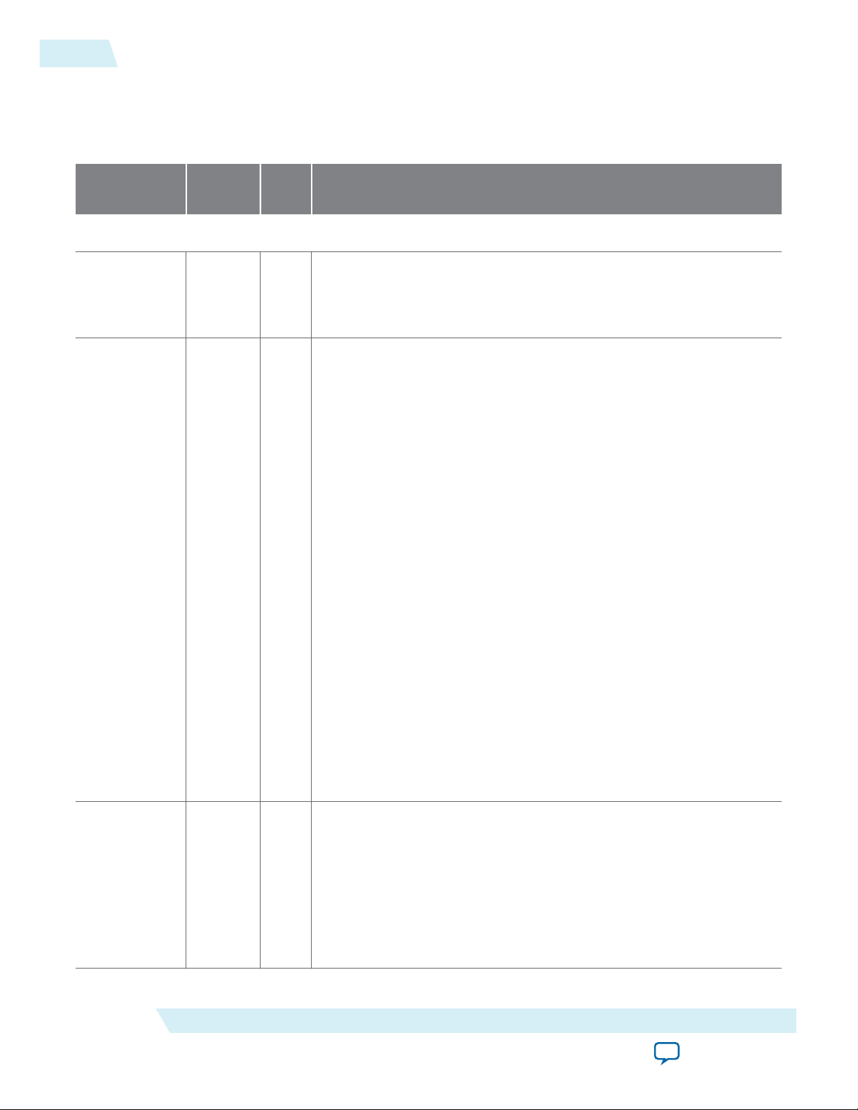
5-4
100G Interlaken IP Core User Data Transfer Interface Signals
100G Interlaken IP Core User Data Transfer Interface Signals
Table 5-4: 100G Interlaken IP Core User Data Transfer Interface
UG-01128
2015.05.04
Signal Name Direction Width
(Bits)
Description
100G Interlaken IP Core Transmit User Interface
itx_chan Input 8 Transmit logic channel number. The IP core supports up to 256
channels. The 100G Interlaken IP core samples this value only when a
bit of itx_sop or itx_sob is high and itx_num_valid has a non-zero
value.
itx_num_
valid
Input 8 itx_num_valid[7:4] specifies the number of valid 64-bit words in the
current packet in the current data symbol. The maximum value of
itx_num_valid[7:4] is eight, because a data symbol on the 512 bit
wide data path has eight words (8 x 64 bits = 512 bits).
In non-valid cycles, you must set the value of itx_num_valid[7:4] to
zero.
In valid cycles, you must set the value of itx_num_valid[7:4] as
follows:
• 4’b1000: if all eight words contain valid data from the current
packet.
• 4’b0xxx: where xxx indicates the number of valid words that are
part of the current packet, if the number is less than eight. Data is
always MSB aligned (left aligned). For example, the value of 4’b0111
indicates that word 0 (bit [63:0]) is not valid.
itx_sop
Altera Corporation
In dual segment mode, if the value of itx_num_valid[7:4] is four or
less (but not zero), the application can hold itx_num_valid[2] high to
indicate the current data symbol also includes the first four 64-bit
words of a new packet. The only valid values for itx_num_valid[3:0]
are 4'b0100 and 4'b0000.
When itx_num_valid[3:0] has the value of 4'b0100, you must also
hold itx_sop[0] high.
You must set the value of itx_num_valid to zero in all non-valid
cycles, even when itx_ready is not asserted.
Input 2 Indicates the current data symbol on itx_din_words contains the start
of a packet (SOP). This signal has the following valid values:
• 2'b00—The current data symbol does not contain the start of a
packet.
• 2'b10— If itx_sop[1] has the value of 1, the start-of-packet aligns
with the most significant byte (byte 63) of the data.
• 2'b01— If itx_sop[0] has the value of 1, the start-of-packet aligns
with byte 31 of the data.
100G Interlaken MegaCore Function Signals
Send Feedback
Page 63
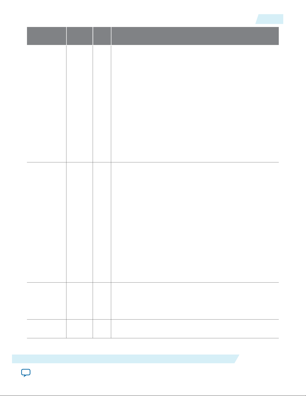
UG-01128
2015.05.04
100G Interlaken IP Core User Data Transfer Interface Signals
5-5
Signal Name Direction Width
(Bits)
itx_
eopbits
Input 4 Indicates whether the current data symbol contains the end of a packet
(EOP) with or without an error, and specifies the number of valid bytes
Description
in the current end-of-packet, non-error 8-byte data word, if relevant.
You must set the value of itx_eopbits as follows:
• 4b’0000: no end of packet, no error.
• 4b’0001: Error and end of packet.
• 4b’1xxx: End of packet. xxx indicates the number of valid bytes in
the final valid 8-byte word of the packet, as follows:
• 3b’000: all 8 bytes are valid.
• 3b’001: 1 byte is valid.
• ...
• 3b’111: 7 bytes are valid.
All other values (4'b01xx, 4'b001x) are undefined.
The valid bytes always start in bit positions [63:56] of the final valid
data word of the packet.
itx_sob Input 2 Indicates the current data symbol contains the start of a burst (SOB). If
the 100G Interlaken IP core is in Interleaved mode, you are responsible
for providing this start of the burst signal. If the100G Interlaken IP
core is in Packet mode, the IP core ignores this signal. The
100G Interlaken IP core samples the itx_chan signal during this cycle.
This signal has the following valid values:
• 2'b00—The current data symbol does not contain the start of a
burst.
• 2'b10— If itx_sob[1] has the value of 1, the start-of-burst aligns
with the most significant byte (byte 63) of the data.
• 2'b01— If itx_sob[0] has the value of 1, the start-of-burst aligns
with byte 31 of the data.
Typically, you use this mode for sending interleaved packets. However,
you can still send non-interleaved packets as long as you provide the
itx_sob and itx_eob signal values. You are responsible to comply
with the BurstMax and BurstMin parameters. If the burst you send is
too large, it can overflow the 100G Interlaken transmit buffer.
itx_eob Input 1 End of the burst. If the 100G Interlaken IP core is in Interleaved mode,
you are responsible for providing this end of the burst signal. If
the100G Interlaken IP core is in Packet mode, the IP core ignores this
signal. You are responsible to comply with the BurstMax and BurstMin
parameters.
itx_din_
words
Input
512
The eight 64-bit words of input data (one data symbol). When itx_
num_valid has the value of zero, the IP core ignores itx_din_words.
100G Interlaken MegaCore Function Signals
Send Feedback
Altera Corporation
Page 64

5-6
100G Interlaken IP Core User Data Transfer Interface Signals
UG-01128
2015.05.04
Signal Name Direction Width
(Bits)
itx_
calendar
Input 16 N Multiple pages (16 bits per page) of calendar input bits. The
100G Interlaken IP Core copies these bits to the in-band flow control
Description
bits in N control words that it sends on the Interlaken link. N is the
value of the Number of calendar pages parameter, which can be any of
1, 2, 4, 8. or 16. This signal is synchronous with tx_usr_clk, although
it is not part of the user data transfer protocol.
itx_ready Output 1 Flow control signal to back pressure transmit traffic. When this signal
is high, you can send traffic to the IP core. When this signal is low, you
should stop sending traffic to the IP core within one to four cycles.
You can consider the inverse of itx_ready to be a FIFO-almost-full
indicator. In full duplex mode, itx_ready is low when rx_lanes_
aligned is low.
itx_ifc_
err
Output 1
Indicates the transmit side user data transfer interface received traffic
that the 100G Interlaken IP Core does not support. The IP core asserts
the itx_ifc_err signal in the following cases:
• In Interleaved mode, the IP core receives a burst that exceeds the
size of MaxBurst.
• itx_sop or itx_sob has the invalid value of 2'b11 in a valid data
cycle.
• Two instances of non-zero itx_sop (a start of packet), or two
instances of non-zero itx_sob (a start of burst), are separated by
fewer than 64 bytes.
The IP core asserts the itx_ifc_err signal for a single clock cycle. The
signal pulses within the current burst, with a delay of one or two cycles
after the error on the transmit side user data transfer interface.
100G Interlaken IP Core Receive User Interface
irx_chan Output 8 Receive logic channel number. The IP core supports up to 256
channels. You should sample this value when a bit of irx_sop or irx_
sob is high and irx_num_valid has a non-zero value.
Altera Corporation
100G Interlaken MegaCore Function Signals
Send Feedback
Page 65

UG-01128
2015.05.04
100G Interlaken IP Core User Data Transfer Interface Signals
5-7
Signal Name Direction Width
(Bits)
irx_num_
valid
Output 8 irx_num_valid[7:4] specifies the number of valid 64-bit words in the
Description
current packet in the current data symbol. The maximum value of
irx_num_valid[7:4] is eight, because a data symbol on the 512 bit
wide data path has eight words (8 x 64 bits = 512 bits).
In valid cycles, the IP core sets the value of irx_num_valid[7:4] as
follows:
• 4’b1000: if all eight words contain valid data from the current
packet.
• 4’b0xxx: where xxx indicates the number of valid words that are
part of the current packet, if the number is less than eight. Data is
always MSB aligned (left aligned). For example, the value of 4’b0111
indicates that word 0 (bit [63:0]) is not valid.
In dual segment mode, if the value of irx_num_valid[7:4] is four or
less (but not zero), the IP core can hold irx_num_valid[2] high to
indicate the current data symbol also includes the first four 64-bit
words of a new packet. The only valid values for irx_num_valid[3:0]
are 4'b0100 and 4'b0000.
When irx_num_valid[3:0] has the value of 4'b0100, the IP core also
holds irx_sop[0] high.
irx_sop
The IP core sets the value of irx_num_valid to zero in all non-valid
cycles.
Output 2 Indicates the current data symbol on irx_dout_words contains the
start of a packet (SOP). This signal has the following valid values:
• 2'b00—The current data symbol does not contain the start of a
packet.
• 2'b10— If irx_sop[1] has the value of 1, the start-of-packet aligns
with the most significant byte (byte 63) of the data.
• 2'b01— If irx_sop[0] has the value of 1, the start-of-packet aligns
with byte 31 of the data. This value is valid only in variations
configured in dual segment mode.
100G Interlaken MegaCore Function Signals
Send Feedback
Altera Corporation
Page 66

5-8
100G Interlaken IP Core User Data Transfer Interface Signals
UG-01128
2015.05.04
Signal Name Direction Width
(Bits)
irx_
eopbits
Output 4 Indicates whether the current data symbol contains the end of a packet
(EOP) with or without an error, and specifies the number of valid bytes
Description
in the current end-of-packet, non-error 8-byte data word, if relevant.
The IP core sets the value of irx_eopbits as follows:
• 4b’0000: no end of packet, no error.
• 4b’0001: Error and end of packet.
• 4b’1xxx: End of packet. xxx indicates the number of valid bytes in
the final valid 8-byte word of the packet, as follows:
• 3b’000: all 8 bytes are valid.
• 3b’001: 1 byte is valid.
• ...
• 3b’111: 7 bytes are valid.
All other values (4'b01xx, 4'b001x) are undefined and are not generated
by the IP core.
The valid bytes always start in bit positions [63:56] of the final valid
data word of the packet.
irx_sob Output 2 Start of the burst. The 100G Interlaken IP core indicates the start of the
burst. The signal irx_channel is only valid when irx_sob is high. This
signal toggles in Packet Mode and in Interleaved Mode.
This signal has the following valid values:
• 2'b00—The current data symbol does not contain the start of a
burst.
• 2'b10— If irx_sob[1] has the value of 1, the start-of-burst aligns
with the most significant byte (byte 63) of the data.
• 2'b01— If irx_sob[0] has the value of 1, the start-of-burst aligns
with byte 31 of the data.
irx_eob Output 1 End of the burst. The 100G Interlaken IP core indicates the end of the
burst. This signal toggles in Packet Mode and in Interleaved Mode.
irx_dout_
words
irx_
calendar
Output
Output 16 × N Multiple pages (16 bits per page) of calendar output bits. The value is
512
The eight 64-bit words of output data (one data symbol). When irx_
num_valid has the value of zero, you should ignore irx_dout_words.
the in-band flow control bits from N control words on the incoming
Interlaken link. N is the value of the Number of calendar pages
parameter, which can be any of 1, 2, 4, 8, or 16. This signal is synchro‐
nous with rx_usr_clk, although it is not part of the user data transfer
protocol.
Altera Corporation
100G Interlaken MegaCore Function Signals
Send Feedback
Page 67

UG-01128
2015.05.04
100G Interlaken IP Core Interlaken Link and Miscellaneous Interface Signals
5-9
Signal Name Direction Width
(Bits)
irx_err Output 1
Indicates an errored packet. This signal is valid only when both
irx_num_valid[7:4] and irx_eopbits[3:0] are non-zero. When a
CRC24 or other error occurs, the 100G Interlaken IP core asserts this
signal for all open channel packets to label them all as errored packets,
because the IP core cannot assign the error to a specific channel.
Related Information
• Data Format on page 3-6
Describes the parameter to select single segment or dual segment mode.
• Dual Segment Mode on page 4-8
Describes the dual segment mode.
• 100G Interlaken IP Core RX Errored Packet Handling on page 4-24
Describes the behavior of the irx_err signal.
• Transfer Mode Selection on page 3-6
Describes the parameter to select Packet or Interleaved mode.
• Interleaved and Packet Modes on page 4-7
Describes the Packet and Interleaved modes.
Description
100G Interlaken IP Core Interlaken Link and Miscellaneous Interface
Signals
Table 5-5: 100G Interlaken IP Core SERDES Signals, Burst Parameter Signals, and Real Time Status Signals
Signal Name Direction Width (Bits) Description
SERDES Pins
rx_pin Input Number of lanes Receiver SERDES data pin on the RX Interlaken
link.
tx_pin Output Number of lanes Transmit SERDES data pin on the TX
Interlaken link.
TX Burst Control Settings
100G Interlaken MegaCore Function Signals
Send Feedback
Altera Corporation
Page 68

5-10
100G Interlaken IP Core Interlaken Link and Miscellaneous Interface Signals
Signal Name Direction Width (Bits) Description
burst_max_in Input 4 Encodes the BurstMax parameter for the IP
core. The actual value of the BurstMax
parameter must be a multiple of 64 bytes. While
traffic is present, this input signal should
remain static. However, when no traffic is
present, you can modify the value of the burst_
max_in signal to modify the BurstMax value of
the IP core.
The 100G InterlakenIP core supports the
following valid values for this signal:
2: 128 bytes
4: 256 bytes
8: 512 bytes
burst_short_in Input 4 Encodes the BurstShort parameter for the IP
core.
The 100G Interlaken IP core supports the
following valid value for this parameter:
UG-01128
2015.05.04
2: 64 bytes
In general, the presence of the BurstMin
parameter makes the BurstShort parameter
obsolete.
burst_min_in Input 4 Encodes the BurstMin parameter for the IP
core.
The IP core supports the following valid values
for this signal:
0: Disable optional enhanced scheduling. Altera
recommends you do not drive this value in
variations in dual segment mode. If you disable
enhanced scheduling, performance is nonoptimal.
2: 64 bytes
4: 128 bytes
The BurstMin parameter should have a value
that is less than or equal to half of the value of
the BurstMax parameter.
Altera recommends that you modify the value
of this input signal only when no traffic is
present on the TX user data interface. You do
not need to reset the IP core.
Real-Time Transmit Status Signals (Synchronous with tx_usr_clk)
Altera Corporation
100G Interlaken MegaCore Function Signals
Send Feedback
Page 69

UG-01128
2015.05.04
100G Interlaken IP Core Interlaken Link and Miscellaneous Interface Signals
Signal Name Direction Width (Bits) Description
5-11
tx_lanes_
aligned
itx_hungry Output 1 A dynamic status flag indicating that a
Output 1 All of the transmitter lanes are aligned and are
ready to send traffic.
downstream buffer which supplies data to the
PCS is running empty. The IP core handles this
situation by inserting IDLE symbols (IDLE
control words) in the packet stream. Therefore,
this signal does not indicate an error.
This signal is asserted for the duration of the
condition it indicates.
The PCS runs continuously with the provided
data or inserted IDLE symbols. This signal is
usually asserted immediately after the IP core
comes out of reset. However, the signal can also
be asserted during normal operation, and is not
a cause for concern.
itx_overflow Output 1 An error flag indicating that the PCS buffer is
currently overflowing. This signal is asserted for
the duration of the overflow condition: it is
asserted in the first clock cycle in which the
overflow occurs, and remains asserted until the
PCS buffer pointers indicate that no overflow
condition exists.
itx_underflow Output 1 An error flag indicating that the PCS buffer is
currently underflowed. In normal operation,
this signal may be asserted temporarily
immediately after the 100G Interlaken IP core
comes out of reset. It is asserted as a single cycle
wide pulse.
Real-Time Receiver Status Signals (Synchronous with rx_usr_clk )
sync_locked Output Number of lanes Receive lane has locked on the remote
transmitter Meta Frame. These signals are level
signals: all bits are expected to stay high unless a
problem occurs on the serial line.
word_locked Output Number of lanes Receive lane has identified the 67-bit word
boundaries in the serial stream. These signals
are level signals: all bits are expected to stay high
unless a problem occurs on the serial line.
rx_lanes_
aligned
Output 1 All of the receiver lanes are aligned and are
ready to receive traffic. This signal is a level
signal.
100G Interlaken MegaCore Function Signals
Send Feedback
Altera Corporation
Page 70

5-12
100G Interlaken IP Core Interlaken Link and Miscellaneous Interface Signals
Signal Name Direction Width (Bits) Description
crc24_err Output 1 A CRC24 error flag covering both control word
and data word. This signal does not associate
the CRC24 error with a particular packet.
Instead, its value indicates the overall SERDES
status. You can use this signal to count the
number of CRC24 errors.
This signal is asserted as a single cycle wide
pulse. If the IP core detects back-to-back
CRC24 errors, this signal toggles.
crc32_err Output Number of lanes An error flag indicating diagnostic CRC32
failures per lane. This signal is asserted as a
single cycle wide pulse. If back-to-back CRC32
errors are detected, this signal toggles.
irx_overflow Output 1 An error flag indicating the presence of
excessive jitter at the receiver side. This signal is
included in the current IP core opportunisti‐
cally for diagnostic purposes.
UG-01128
2015.05.04
rdc_overflow Output 1 An error flag indicating that the RX domain-
crossing FIFO is currently overflowed. The RX
domain-crossing FIFO transfers data from the
PCS clock domain to the MAC clock domain.
rg_overflow Output 1 An error flag indicating that the Reassembly
FIFO is currently overflowed. The Reassembly
FIFO is the receiver FIFO that feeds directly to
the user data interface.
rxfifo_fill_
level
Output RXFIFO_ADDR_
WIDTH
The fill level of the Reassembly FIFO, in units of
64-bit words. The width of this signal is the
value of the RXFIFO_ADDR_WIDTH
parameter, which is 12 by default. You can use
this signal to monitor when the RX Reassembly
FIFO is empty.
sop_cntr_inc Output 1 A pulse indicating that the 100G Interlaken IP
core receiver user data interface received a startof-packet. You can use this signal to increment
a count of SOPs the application observes on the
receive interface.
eop_cntr_inc Output 1 A pulse indicating that the 100G Interlaken IP
core receiver user data interface received an
end-of-packet. You can use this signal to
increment a count of EOPs the application
observes on the receive interface.
Altera Corporation
100G Interlaken MegaCore Function Signals
Send Feedback
Page 71

UG-01128
2015.05.04
Related Information
RXFIFO Address Width on page 9-2
Information about programming the depth of the Reassembly FIFO with the RXFIFO_ADDR_WIDTH
parameter.
100G Interlaken IP Core Management Interface
The 100G Interlaken IP core management interface allows you to communicate with IP core internal
status and control registers. This interface manages the PMA (resets and serial loopback controls) and
PCS control and status registers. This interface does not provide access to the hard PCS registers on the
device.
The management interface is a typical 32-bit memory-mapped register port. It complies with the Avalon
Memory-Mapped (Avalon-MM) specification defined in the Avalon Interface Specifications.
Table 5-6: 100G Interlaken IP Core Management Interface Signals
100G Interlaken IP Core Management Interface
5-13
Signal Name Direction Width
(Bits)
Description
100G Interlaken IP Core Management Interface Signals
mm_clk Input 1 Management clock. Clocks the register accesses. It is
also used for clock rate monitoring and some analog
calibration procedures. You must run this clock at a
frequency in the range of 100 MHz–125 MHz.
mm_read Input 1 Read access to the register ports.
mm_write Input 1 Write access to the register ports.
mm_addr Input 16 Address to access the register ports.
mm_rdata Output 32 When mm_rdata_valid is high, mm_rdata holds valid
read data.
mm_rdata_valid Output 1 Valid signal for mm_rdata.
mm_wdata Input 32 When mm_write is high, mm_wdata holds valid write
data.
If you do not use the management interface, drive the management inputs as follows:
• mm_clk must connect to a stable clock. However, the clock signal need not be of unusually high quality.
• mm_read and mm_write must be tied to zero.
100G Interlaken MegaCore Function Signals
Send Feedback
Altera Corporation
Page 72

mm_clk
mm_write
mm_addr[15:0]
mm_wdata[31:0]
Don’t Care
0x0012 0x0013 Don’t Care
Don’t Care
wdata0 wdata1 Don’t Care
mm_clk
mm_read
mm_addr[15:0]
mm_rdata_valid
mm_rdata[31:0]
Don’t Care
0x0000 0x0001 Don’t Care
Previous Value
rdata0 rdata1
5-14
Device Dependent Signals
If you use the management interface, drive the control lines as shown in the examples and observing the
following constraints:
• During a write operation, you must maintain the the mm_write signal asserted for at least two clock
cycles. Back-to-back writes must be separated by at least one clock cycle.
• During a read operation, you must maintain the mm_read signal asserted for at least two clock cycles.
Back-to-back reads must be separated by at least one clock cycle.
Figure 5-1: 100G Interlaken IP Core Management Interface Write Operation
Shows the timing requirements for a write operation on the 100G Interlaken IP core management
interface.
UG-01128
2015.05.04
Figure 5-2: 100G Interlaken IP Core Management Interface Read Operation
Shows the timing requirements for a read operation on the 100G Interlaken IP core management
interface. The IP core asserts the mm_rdata_valid signal two cycles after the mm_read signal is asserted.
Related Information
Avalon Interface Specifications
Device Dependent Signals
Some of the 100G Interlaken MegaCore function signals depend on the device that your variation targets.
Variations that target an Arria V device or a Stratix V device have an interface to connect to an Altera
Transceiver Reconfiguration Controller that you must instantiate outside the 100G Interlaken IP core for
successful functioning in hardware. Variations that target an Arria 10 device have Arria 10-specific
Altera Corporation
100G Interlaken MegaCore Function Signals
Send Feedback
Page 73

UG-01128
2015.05.04
Transceiver Reconfiguration Controller Interface Signals
requirements to support the Arria 10 transceivers. The following 100G Interlaken IP core interfaces are
device specific:
Transceiver Reconfiguration Controller Interface Signals on page 5-15
Arria 10 External PLL Interface Signals on page 5-15
Arria 10 Transceiver Reconfiguration Interface Signals on page 5-16
Transceiver Reconfiguration Controller Interface Signals
100G Interlaken IP core variations that target an Arria V or a Stratix V device require an external reconfi‐
guration controller to function correctly in hardware. 100G Interlaken IP core variations that target an
Arria 10 device include a reconfiguration controller block and do not require an external reconfiguration
controller.
Table 5-7: 100G Interlaken IP Core Arria V and Stratix V Transceiver Reconfiguration Controller Interface
Signals
5-15
Signal Name Direction Width
(Bits)
reconfig_to_xcvr Input 70 bits
per
reconfi‐
guration
interface.
reconfig_from_xcvr Output 46 bits
per
reconfi‐
guration
interface
Description
Bus from the external transceiver reconfiguration
controller to the 100G Interlaken IP core. The bus
includes signals fro multiple transceiver reconfigura‐
tion interfaces. The reconfiguration controller has one
interface to control each transceiver channel (one per
Interlaken lane) plus one interface to control each TX
PLL configured in the IP core. The width of each
reconfiguration controller output reconfiguration
interface is 70 bits.
Bus to the external transceiver reconfiguration
controller from the 100G Interlaken IP core. The bus
includes signals for multiple reconfiguration
interfaces of the transceiver reconfiguration
controller. The reconfiguration controller has one
interface for each transceiver channel (one per
Interlaken lane) plus one interface for each TX PLL
configured in the IP core. The width of each reconfi‐
guration controller input reconfiguration interface is
46 bits.
Arria 10 External PLL Interface Signals
100G Interlaken IP core variations that target an Arria 10 device require an external transceiver PLL to
function correctly in hardware. 100G Interlaken IP core variations that target an Arria V or Stratix V
device include the transceiver PLLs and do not require that you configure any additional PLLs.
100G Interlaken MegaCore Function Signals
Send Feedback
Altera Corporation
Page 74
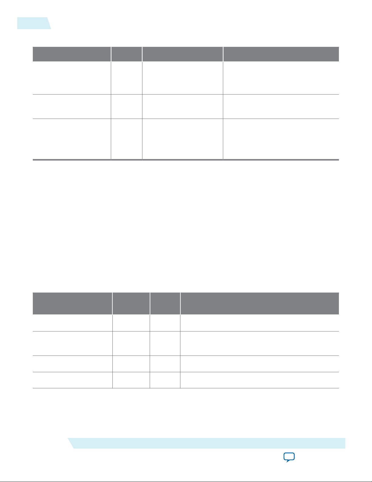
5-16
Arria 10 Transceiver Reconfiguration Interface Signals
Table 5-8: 100G Interlaken IP Core Arria 10 External PLL Interface Signals
Signal Name Direction Width (Bits) Description
tx_serial_clk Input NUM_LANES High-speed clock for Arria 10
transceiver channel, provided from
external TX PLL.
tx_pll_locked Input 1 PLL-locked indication from external
TX PLL.
UG-01128
2015.05.04
tx_pll_powerdown
Output 1 Output signal from the IP core
internal reset controller. The IP core
asserts this signal to tell the external
PLLs to power down.
Related Information
Adding the External PLL on page 2-12
Arria 10 Transceiver Reconfiguration Interface Signals
The 100G Interlaken IP core Arria 10 transceiver reconfiguration interface allows you to communicate
with Arria 10 hard PCS registers. This interface is available only in variations that target an Arria 10
device. You use this interface to reconfigure the transceiver and to take advantage of built-in transceiver
features that the 100G Interlaken IP Core supports for IP core testing. The interface allows you to address
a single register in a single transceiver channel at one time.
The Arria 10 transceiver reconfiguration interface is a typical 32-bit memory-mapped register port. It
complies with the Avalon Memory-Mapped (Avalon-MM) specification defined in the Avalon Interface
Specifications.
Table 5-9: 100G Interlaken IP Core Arria 10 Transceiver Reconfiguration Interface Signals
Signal Name Direction Width
(Bits)
Description
reconfig_clk Input 1
reconfig_reset Input 1 Assert this signal to reset the Arria 10 transceiver
reconfig_read Input 1 Read access to the Arria 10 hard PCS registers.
reconfig_write Input 1 Write access to the Arria 10 hard PCS registers.
Altera Corporation
Arria 10 transceiver reconfiguration interface clock.
reconfiguration interface.
100G Interlaken MegaCore Function Signals
Send Feedback
Page 75
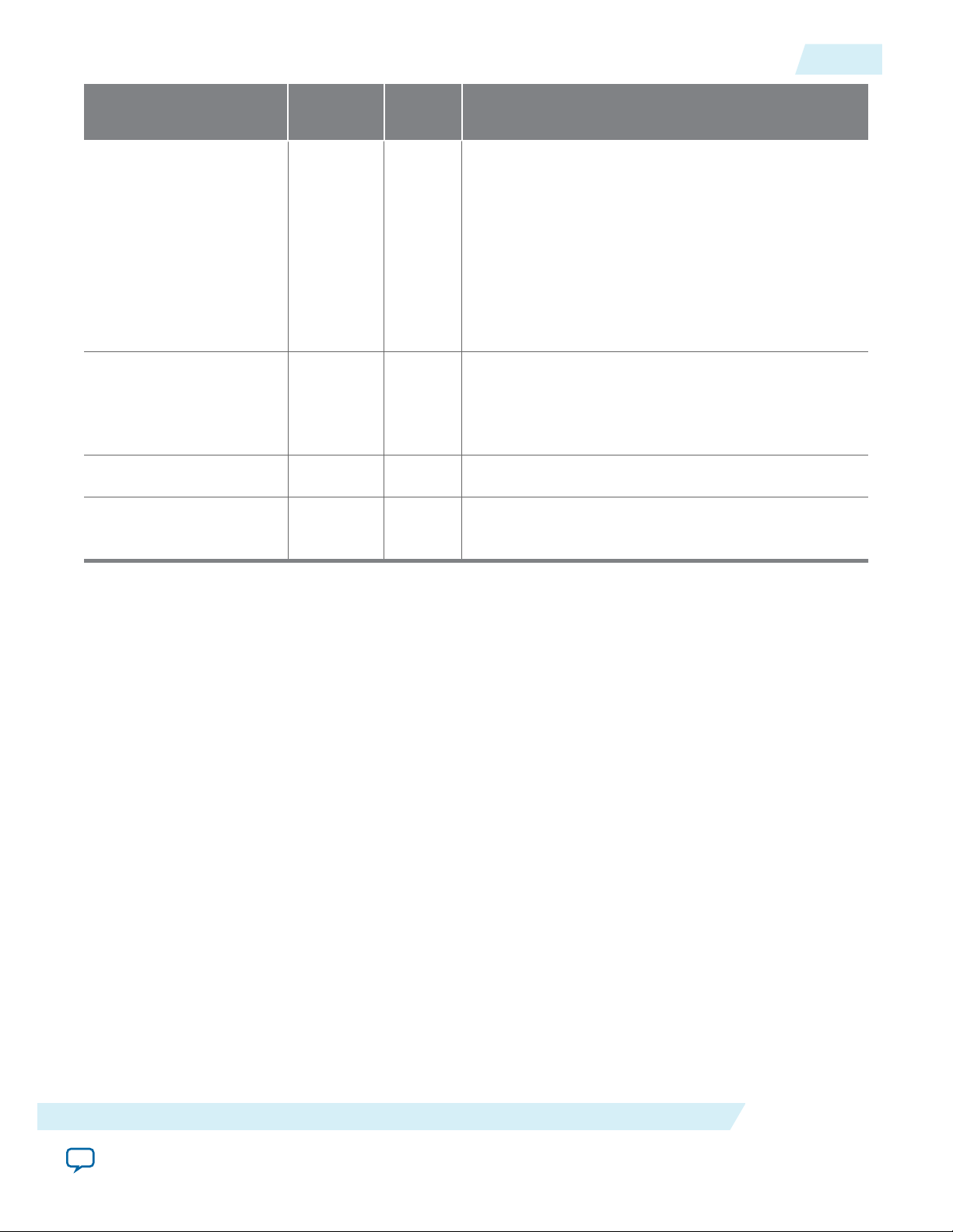
UG-01128
2015.05.04
Arria 10 Transceiver Reconfiguration Interface Signals
5-17
Signal Name Direction Width
Description
(Bits)
reconfig_address Input 14 or 15 Address to access the hard PCS registers. This signal
holds both the hard PCS register offset and the
transceiver channel being addressed, in the following
fields:
• [8:0]: register offset in the hard PCS
• [N:9]: Interlaken lane number
• In 12-lane variations, N is 13
• In 24-lane variations, N is 14
reconfig_readdata Output 32 After user logic asserts the reconfig_read signal,
when the IP core deasserts the reconfig_
waitrequest signal, reconfig_readdata holds valid
read data.
reconfig_waitrequest Output 1 Busy signal for reconfig_readdata.
reconfig_writedata Input 32 When reconfig_write is high, reconfig_writedata
holds valid write data.
Related Information
Avalon Interface Specifications
Defines the Avalon-MM interface specification, including the behavior of the output signals and the
expected behavior of the input signals.
100G Interlaken MegaCore Function Signals
Send Feedback
Altera Corporation
Page 76

2015.05.04
www.altera.com
101 Innovation Drive, San Jose, CA 95134
100G Interlaken IP Core Register Map
6
UG-01128
Subscribe
Send Feedback
The 100G Interlaken IP core control registers are 32 bits wide and are accessible to you using the
management interface, an Avalon-MM interface which conforms to the Avalon Interface Specifications.
This table lists the registers available in the IP core. All unlisted locations are reserved.
Table 6-1: 100G Interlaken IP Core Register Map
Offset Name R/W Description
9'h0
PCS_BASE
RO [31:8] – Constant “HSi” ASCII
[7:0] – version number
Despite its name, this register does not encode the hard PCS
base address.
9'h1
LANE_COUNT
RO Number of lanes
9'h2 TEMP_SENSE RO Device temperature according to the internal temperature
sensing diode.
[7:0] – the temperature in degrees Fahrenheit
[15:8] – the temperature in degrees Celsius
For example, when the temperature is 54 degrees Celsius
(130 degrees Fahrenheit), the value of the register is 0x3682.
To interpret this register value, you read 0x36 (decimal 54)
to be the temperature in degrees Celsius, and you read 0x82
(decimal 130) to be the temperature in degrees Fahrenheit.
This register is invalid in the following IP core variations:
• Variations that target an Arria 10 device
• Variations in which you turn off the hidden parameter
Include Temp Sense
9'h3 ELAPSED_SEC RO [23:0] - Elapsed seconds since power up. The IP core
calculates this value from the management interface clock
(mm_clk) for diagnostic purposes. During continuous
operation, this value rolls over every 194 days.
©
2015 Altera Corporation. All rights reserved. ALTERA, ARRIA, CYCLONE, ENPIRION, MAX, MEGACORE, NIOS, QUARTUS and STRATIX words and logos are
trademarks of Altera Corporation and registered in the U.S. Patent and Trademark Office and in other countries. All other words and logos identified as
trademarks or service marks are the property of their respective holders as described at www.altera.com/common/legal.html. Altera warrants performance
of its semiconductor products to current specifications in accordance with Altera's standard warranty, but reserves the right to make changes to any
products and services at any time without notice. Altera assumes no responsibility or liability arising out of the application or use of any information,
product, or service described herein except as expressly agreed to in writing by Altera. Altera customers are advised to obtain the latest version of device
specifications before relying on any published information and before placing orders for products or services.
ISO
9001:2008
Registered
Page 77
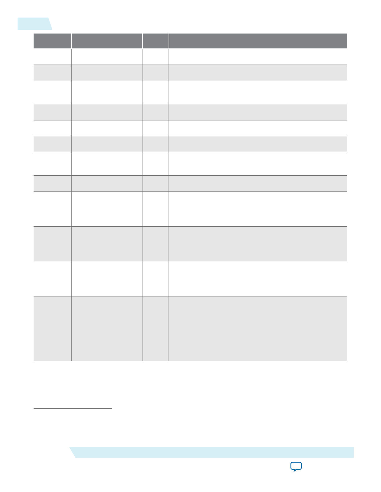
6-2
100G Interlaken IP Core Register Map
Offset Name R/W Description
9'h4 TX_EMPTY RO [NUM_LANES–1:0] – Transmit FIFO status (empty)
9'h5 TX_FULL RO [NUM_LANES–1:0] – Transmit FIFO status (full)
9'h6 TX_PEMPTY RO [NUM_LANES–1:0] – Transmit FIFO status (partially
empty)
9'h7 TX_PFULL RO [NUM_LANES–1:0] – Transmit FIFO status (partially full)
UG-01128
2015.05.04
9'h8
9'h9
9'hA
9'hB
RX_EMPTY
RX_FULL
RX_PEMPTY
RX_PFULL
9'hC REF_KHZ
9'hD RX_KHZ
(1)
9'hE TX_KHZ
9'hF
LANE_PROFILE
(1)
(1)
RO [NUM_LANES–1:0] – Receive FIFO status (empty)
RO [NUM_LANES–1:0] – Receive FIFO status (full)
RO [NUM_LANES–1:0] – Receive FIFO status (partially
empty)
RO [NUM_LANES–1:0] – Receive FIFO status (partially full)
RO PLL reference clock frequency (kHz)
If you turn off Include diagnostic features, this register is
not available.
RO RX recovered clock frequency (kHz)
If you turn off Include diagnostic features, this register is
not available.
RO TX serial clock frequency (kHz)
If you turn off Include diagnostic features, this register is
not available.
RO [NUM_LANES–1:0] – Mask delineating the transceivers
this IP core uses on the device. For example, if the FPGA
has 24 lanes on one side of the device and the IP core uses
the bottom twelve transceivers, the mask would be
24'b000000_000000_111111_111111..
(1)
Altera recommends that you use this register only during hardware operation. During simulation, you
should not rely on the value in this register, because the amount of simulation time required for the IP core
to provide consistent values in the REF_KHZ, RX_KHZ, and TX_KHZ registers is too long.
Altera Corporation
This register is not available in IP core variations that target
an Arria 10 device.
100G Interlaken IP Core Register Map
Send Feedback
Page 78
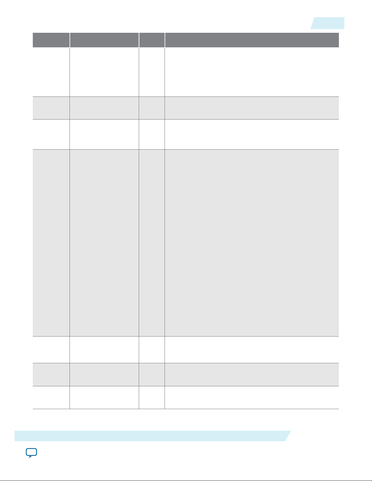
UG-01128
2015.05.04
100G Interlaken IP Core Register Map
Offset Name R/W Description
6-3
9'h10
9'h11
9'h12
9'h13
PLL_LOCKED
FREQ_LOCKED
LOOPBACK
RESET
RO In Arria 10 devices: [0] – Transmit PLL lock indication.
In other device families: [Number of transceiver blocks–1:0]
– Transceiver block transmit PLL n lock indication. One
lock indicator per transceiver block. Bits that correspond to
unused transceiver block PLLs are forced to 1.
RO [NUM_LANES–1:0] – Clock data recovery is frequency
locked on the inbound data stream
RW [NUM_LANES–1:0] – For each lane, write a 1 to activate
internal TX to RX serial loopback mode, or write a 0 to
disable the loopback for normal operation.
RW Bit 9 : 1 = Force lock to data mode
Bit 8 : 1 =Force lock to reference mode
Bit 7 : 1 = Synchronously clear the TX-side error counters
and sticky flags
Bit 6 : 1 = Synchronously clear the RX-side error counters
and sticky flags
Bit 5 : 1 =Program load mode: perform a sequence of DMA
reads. Currently the IP core supports only the value of 1'b0,
indicating a processor controls the read operations.
9'h20
9'h21
9'h22
ALIGN
WORD_LOCK
SYNC_LOCK
Bit 4 : 1 = Ignore the RX analog reset
Bit 3 : 1 = Reset the soft microcontroller
Bit 2 : 1 = Reset the transmitter and the receiver
Bit 1 : 1 = Reset the receiver
Bit 0 : 1 =Ignore RX digital resets
The normal operating state for this register is all zeroes, to
allow automatic reset control. These bits are intended
primarily for hardware debugging use. Bit 2 is a good
general purpose soft reset. Bits 6 and 7 are convenient for
monitoring long stretches of error-free operation.
RO Bit 12 : TX lanes are aligned
Bit 0 : RX lanes are aligned.
RO [NUM_LANES–1:0] – Word (block) boundaries have been
identified in the RX stream.
RO [NUM_LANES–1:0] – Metaframe synchronization has been
achieved.
100G Interlaken IP Core Register Map
Send Feedback
Altera Corporation
Page 79
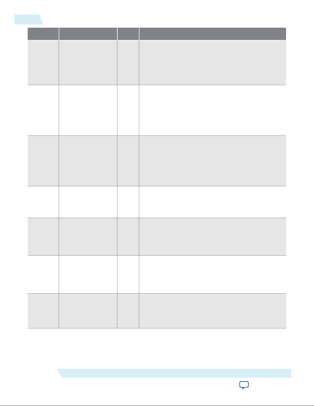
6-4
100G Interlaken IP Core Register Map
Offset Name R/W Description
UG-01128
2015.05.04
9'h23
9'h24
9'h25
9'h27
CRC0
CRC1
CRC2
SH_ERR
RO 4 bit counters indicating CRC errors in lanes 7,6,5,4,3,2,1,0.
These will saturate at F, and you clear them by setting bit 6
in the RESET register.
If you turn off Include diagnostic features, this register is
not available.
RO 4 bit counters indicating CRC errors in lanes
15,14,13,12,11,10,9,8.
These will saturate at F, and you clear them by setting bit 6
in the RESET register.
If you turn off Include diagnostic features, this register is
not available.
RO 4 bit counters indicating CRC errors in lanes
23,22,21,20,19,18,17,16.
These will saturate at F, and you clear them by setting bit 6
in the RESET register.
If you turn off Include diagnostic features, this register is
not available.
RO [NUM_LANES–1:0] – Sticky flag indicating a sync header
(framing bit) error has occurred in the corresponding RX
lane since this bit was last cleared through the RESET
register.
9'h28 RX_LOA RO Bit [0] – Sticky flag indicating loss of RX side lane-to-lane
alignment since this bit was last cleared through the RESET
register. Typically, the IP core asserts this bit in case of a
catastrophic problem such as one or more lanes going
down.
9'h29 TX_LOA RO Bit [0] – Sticky flag indicating loss of TX side lane to lane
alignment since this bit was last cleared through the RESET
register. Typically, the IP core asserts this bit in case of a TX
FIFO underflow / overflow caused by a significant deviation
from the expected data flow rate through the TX PCS.
9'h30
PCS_6SEL
RO Transceiver block selection for PCS test bus. (Factory use
only).
If you turn off Include diagnostic features, this register is
not available.
Altera Corporation
100G Interlaken IP Core Register Map
Send Feedback
Page 80

UG-01128
2015.05.04
100G Interlaken IP Core Register Map
Offset Name R/W Description
6-5
9'h31
9'h32
9'h33
9'h34
9'h35
PCS_LNSEL
PCS_TB
Reserved
RX_PRBS_DONE
RX_PRBS_ERR
RO Lane selection within transceiver block for PCS test bus.
(Factory use only).
If you turn off Include diagnostic features, this register is
not available.
RO PCS test bus. (Factory use only).
If you turn off Include diagnostic features, this register is
not available.
RO [NUM_LANES–1:0] – Indicates whether enough bits have
been received on the corresponding RX lane for one
complete pass through the PRBS polynomial.
If you turn off Include diagnostic features, this register is
not available.
RO [NUM_LANES–1:0] – Sticky flag that indicates whether a
PRBS error has occurred on the corresponding RX lane
after RX_PRBS_DONE has attained the value of 1.
If you turn off Include diagnostic features, this register is
not available.
9'h36
9'h37
9'h38
RX_PRBS_COUNT
RX_PRBS_CTRL
CRC32_ERR_INJECT
RO [7:0] – This eight-bit counter holds the number of words
that had PRBS errors across all lanes. Saturates at the value
of 0xFF.
If you turn off Include diagnostic features, this register is
not available.
RW Bit [0] – If you set this bit to the value of 1, the IP core
clears the RX_PRBS_DONE, RX_PRBS_ERR, and RX_PRBS_
COUNT registers. Reset this bit to the value of 0 to capture
new PRBS status.
If you turn off Include diagnostic features, this register is
not available.
RW [NUM_LANES–1:0] - When a bit has the value of 1, the IP
core injects CRC32 errors on the corresponding TX lane.
When it has the value of 0, the IP core does not inject errors
on the TX lane. You must maintain each bit at the value of 1
for the duration of a Meta Frame, at least, to ensure that the
IP core transmits at least one CRC32 error.
If you turn off Include diagnostic features, this register is
not available.
100G Interlaken IP Core Register Map
Send Feedback
Altera Corporation
Page 81
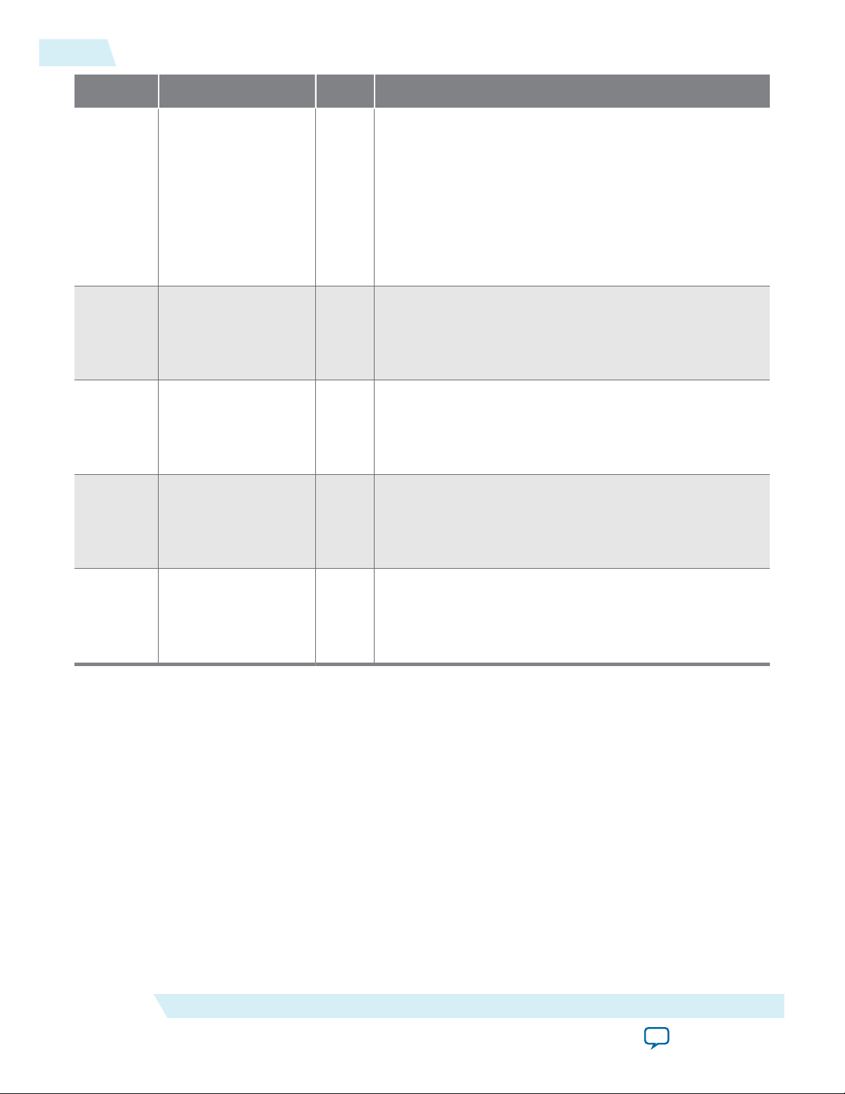
6-6
100G Interlaken IP Core Register Map
Offset Name R/W Description
UG-01128
2015.05.04
9'h102
9'h122
9'h123
9'h124
ERR_INJECT
CNT_ERR_TX
CNT_UNCOR_TX
CNT_ERR_RX
RW Bit [0] - When you write the value of 1 to this register bit,
the IP core TX MAC injects a single bit error in outgoing
Interlaken communication. This bit error will cause one or
possibly more CRC24 errors. Before you can inject a second
error, you must write the value of 0 to this register bit.
Altera recommends that you write the value of 1 and then
write the value of 0 to inject a single bit error.
If you turn off Include diagnostic features, this register is
not available.
RO Number of correctable errors in M20K memory in the TX
MAC logic.
If you turn off Enable M20K ECC support, this register is
not available.
RO Number of uncorrectable errors in M20K memory in the
TX MAC logic.
If you turn off Enable M20K ECC support, this register is
not available.
RO Number of correctable errors in M20K memory in the RX
MAC logic.
9'h125
CNT_UNCOR_RX
Related Information
Avalon Interface Specifications
If you turn off Enable M20K ECC support, this register is
not available.
RO Number of uncorrectable errors in M20K memory in the
RX MAC logic.
If you turn off Enable M20K ECC support, this register is
not available.
Altera Corporation
100G Interlaken IP Core Register Map
Send Feedback
Page 82

2015.05.04
PLL
Loopback
TX Lanes
RX Lanes
Example Design
Top Testbench
Packet
Generator
Control & Status
Registers
Packet
Checker
100G Interlaken
MegaCore
Function
System Clock
Generator
PLL Reference
Clock Generator
TX PLL
www.altera.com
101 Innovation Drive, San Jose, CA 95134
100G Interlaken IP Core Testbench
7
UG-01128
Subscribe
Send Feedback
When you generate an 100G Interlaken IP core variation with Verilog HDLsynthesis and simulation
models, the software generates an example design and testbench to simulate your 100G Interlaken IP core
variation. The testbench provides system and PLL reference clocks and connects the TX output pins of the
IP core to its RX input pins, implementing physical layer loopback.
In simulation, the testbench generates packets on the IP core TX user data transfer interface. The IP core
sends these packets on the loopback Interlaken link. After the IP core receives the packets on the loopback
Interlaken link, it processes the Interlaken packets and transmits them on the RX user data transfer
interface. The testbench checks that the packets it receives on the IP core RX user data transfer interface
are consistent with the packets sent in.
Figure 7-1: 100G Interlaken IP Core Testbench Block Diagram
The TX PLL is present only in the example designs for Arria 10 variations.
©
2015 Altera Corporation. All rights reserved. ALTERA, ARRIA, CYCLONE, ENPIRION, MAX, MEGACORE, NIOS, QUARTUS and STRATIX words and logos are
trademarks of Altera Corporation and registered in the U.S. Patent and Trademark Office and in other countries. All other words and logos identified as
trademarks or service marks are the property of their respective holders as described at www.altera.com/common/legal.html. Altera warrants performance
of its semiconductor products to current specifications in accordance with Altera's standard warranty, but reserves the right to make changes to any
products and services at any time without notice. Altera assumes no responsibility or liability arising out of the application or use of any information,
product, or service described herein except as expressly agreed to in writing by Altera. Altera customers are advised to obtain the latest version of device
specifications before relying on any published information and before placing orders for products or services.
ISO
9001:2008
Registered
Page 83

7-2
100G Interlaken IP Core Testbench Interface Signals
In Arria 10 variations, the example design includes external TX PLLs. You can examine the clear text files
to view sample code that implements one possible method to connect external PLLs to the
100G Interlaken IP core.
The Arria 10 example design packs six Interlaken lanes in a transceiver block, and connects all of the
channels in the same transceiver block to a single ATX PLL. The IP core connects each ATX PLL to the
100G Interlaken IP core tx_pll_locked and tx_pll_powerdown ports. This simple connection model is
only one of many options available to you for configuring and connecting the external PLLs in your
100G Interlaken design.
100G Interlaken IP Core Testbench Interface Signals on page 7-2
Testbench Simulation Behavior on page 7-2
Running the Testbench With the Example Design on page 7-3
100G Interlaken IP Core Testbench Interface Signals
Table 7-1: 100G Interlaken IP Core TestBench Signals
Port Name Direction Width (Bits) Description
UG-01128
2015.05.04
clk50
pll_ref_clk
rx_pin
tx_pin
Related Information
Input 1 System clock input. Clock
Input 1 Transceiver reference clock.
Input Number of lanes Receiver SERDES data pin.
Output Number of lanes Transmit SERDES data pin.
100G Interlaken IP Core Clock Interface Signals on page 5-1
Lists the valid PLL reference clock frequencies.
Testbench Simulation Behavior
During simulation, the 100G Interlaken IP core testbench performs the following actions:
1. Resets the 100G Interlaken IP core.
2. After the reset sequence completes, sends a sequence of Interlaken packets of fixed sizes with
predefined data in the payload to the TX user data transfer interface of the IP core. This action
continues for a preset amount of time.
frequency is 50 MHz.
Drives the RX CDR PLL in Arria
10 variations, and drives both the
TX PLL and the RX PLL in other
variations.
Altera Corporation
100G Interlaken IP Core Testbench
Send Feedback
Page 84

UG-01128
2015.05.04
Running the Testbench With the Example Design
Note: If the IP core is in dual segment mode, the testbench sends 65-byte bursts on the TX user data
transfer interface. If the IP core is in single segment, Interleaved mode, the testbench sends 128byte bursts.
3. Performs a sequence of register read and write operations to demonstrate register access.
4. Resets the 100G Interlaken IP core again.
5. After the reset sequence completes, sends an additional sequence of Interlaken packets of the same
type as in Step 2.
6. Completes the sequence of packets and reports success or failure.
The testbench is not parameterizable — you cannot modify the packet sequence that the testbench
generates for a specific DUT. However, Altera provides the testbench files in cleartext format, and you can
modify the testbench for your own testing purposes. The packet generator included in the testbench can
be used to generate pseudo-random or specific sizes packets.
The packet checker included in the testbench provides the following basic packet checking capabilities:
• Checks that the transmitted packet sequence is not violated
• Checks that the received data matches expected values
Running the Testbench With the Example Design
7-3
Perform the following steps to simulate the testbench example:
1. Setting Up the Testbench Example on page 7-3
2. Simulating the Example Design on page 7-3
Setting Up the Testbench Example
When you generate your 100G Interlaken IP core, if you specify Verilog HDL IP core models, the
resulting file structure includes the example design and the testbench.
Related Information
Specifying the 100G Interlaken IP Core Parameters and Options on page 2-2
Provides instructions to generate the DUT.
Simulating the Example Design
Altera provides simulation scripts for simulating the testbench in the Mentor Graphics Modelsim SE
simulator. However, you can write your own scripts to simulate the testbench in other Altera-supported
simulators. Your script should check that the SOP and EOP counts match after simulation is complete.
To simulate the example design using the Altera-provided scripts, perform the following steps:
1. Ensure IP core generation is complete.
2. Start the Mentor Graphics ModelSim-SE simulation tool.
3. Change directory to the following folder, which contains the generated testbench:
a. <variation>_sim/ilk_core/testbench for Arria V GZ and Stratix V IP core variations.
b. <variation>/ilk_core_<version>/sim/testbench for Arria 10 IP core variations.
4. Type the following command: do vlog.do
The testbench generates a series of packets on the IP core TX user data transfer interface, loops the
resulting Interlaken data transmissions back to the IP core on the Interlaken link, and checks the
100G Interlaken IP Core Testbench
Send Feedback
Altera Corporation
Page 85

7-4
Simulating the Example Design
packets that the IP core generates on the RX user data transfer interface. After simulation completes, a
success or failure notice displays.
UG-01128
2015.05.04
Altera Corporation
100G Interlaken IP Core Testbench
Send Feedback
Page 86

2015.05.04
www.altera.com
101 Innovation Drive, San Jose, CA 95134
100G Interlaken IP Core Test Features
8
UG-01128
Subscribe
Send Feedback
Depending on the features you turn on in the 100G Interlaken parameter editor, your 100G Interlaken IP
core supports the following test features:
Internal Serial Loopback Mode on page 8-1
The 100G Interlaken IP core supports an internal TX to RX serial loopback mode.
External Loopback Mode on page 8-2
The 100G Interlaken IP core operates correctly in an external loopback configuration.
PRBS Generation and Validation on page 8-2
CRC32 Error Injection on page 8-7
CRC24 Error Injection on page 8-8
Internal Serial Loopback Mode
The 100G Interlaken IP core supports an internal TX to RX serial loopback mode.
To turn on internal serial loopback:
• Reset the IP core by asserting the active low reset_n signal.
• After reset completes, set the value of bits [NUM_LANES-1:0] of the LOOPBACK register at offset 0x12
to all ones.
Note:
Refer to "IP Core Reset" for information about the required wait period for register access.
• Monitor the RX lanes aligned bit (bit 0) of the ALIGN register at offset 0x20 or the rx_lanes_aligned
output signal. After the RX lanes are aligned, the IP core is in internal serial loopback mode.
Resetting the IP core turns off internal serial loopback. To turn off internal serial loopback:
• Reset the IP core by asserting the active low reset_n signal. Resetting the IP core sets the value of bits
[NUM_LANES-1:0] of the LOOPBACK register at offset 0x12 to all zeroes.
• Monitor the RX lanes aligned bit (bit 0) of the ALIGN register at offset 0x20 or the rx_lanes_aligned
output signal. After the RX lanes are aligned, the IP core is in normal operational mode.
Related Information
IP Core Reset on page 4-5
Describes the required delay from reset to successful register access attempts.
©
2015 Altera Corporation. All rights reserved. ALTERA, ARRIA, CYCLONE, ENPIRION, MAX, MEGACORE, NIOS, QUARTUS and STRATIX words and logos are
trademarks of Altera Corporation and registered in the U.S. Patent and Trademark Office and in other countries. All other words and logos identified as
trademarks or service marks are the property of their respective holders as described at www.altera.com/common/legal.html. Altera warrants performance
of its semiconductor products to current specifications in accordance with Altera's standard warranty, but reserves the right to make changes to any
products and services at any time without notice. Altera assumes no responsibility or liability arising out of the application or use of any information,
product, or service described herein except as expressly agreed to in writing by Altera. Altera customers are advised to obtain the latest version of device
specifications before relying on any published information and before placing orders for products or services.
ISO
9001:2008
Registered
Page 87

8-2
External Loopback Mode
External Loopback Mode
The 100G Interlaken IP core operates correctly in an external loopback configuration.
To put the IP core in external loopback mode, connect the TX lanes to the RX lanes of the IP core. This
mode does not require any special programming of the IP core.
Related Information
100G Interlaken IP Core Testbench on page 7-1
The testbench simulates the IP core in external loopback mode.
PRBS Generation and Validation
The 100G Interlaken IP core supports generation and validation of several predetermined pseudo-random
binary sequences (PRBS) for Interlaken link testing.
This feature is available if you turn on Include diagnostic features in the 100G Interlaken parameter
editor.
Table 8-1: PRBS Polynomials Available in the 100G Interlaken IP Core
UG-01128
2015.05.04
Pattern
Name
Polynomial
Defined in
Interlaken
Specification
Available in 100G Interlaken IP Core Variations with
Target Device Family
Arria V or Stratix V Arria 10
PRBS7 x7 + x6 + 1 Yes Yes No
PRBS9 x9 + x5 +1 No Yes Yes
PRBS15 x15 + x14 +1 No No Yes
PRBS23 x23 + x18 + 1 Yes Yes Yes
PRBS31 x31 + x28 + 1 Yes Yes Yes
For instructions to activate and use the PRBS test feature in your 100G Interlaken IP core IP core, refer to
one of the following two topics:
Setting up PRBS Mode in Arria V and Stratix V Devices on page 8-2
Setting up PRBS Mode in Arria 10 Devices on page 8-4
Setting up PRBS Mode in Arria V and Stratix V Devices
To enable the IP core to generate PRBS output, you must program the relevant hard PCS registers to
enable the PRBS generator clock, to set the test_enable bit, and to select the PRBS polynomial. To enable
the IP core to receive PRBS input, you must program the relevant hard PCS registers to enable the PRBS
receiver clock, to set the test_enable bit, and to select the expected PRBS polynomial. If you perform your
PRBS testing in loopback mode, you must enable the IP core to both generate and receive PRBS
sequences.
The PRBS feature is available only if you turn on Include diagnostic features in the 100G Interlaken
parameter editor.
Altera Corporation
100G Interlaken IP Core Test Features
Send Feedback
Page 88

UG-01128
2015.05.04
Setting up PRBS Mode in Arria V and Stratix V Devices
This section describes the register values you must program. For instructions to program the registers that
activate the PRBS test feature in your Arria V or Stratix V 100G Interlaken IP core, refer to the hard PCS
register programming instructions in the Native PHY IP Core chapter for your target device family and in
the Transceiver Reconfiguration Controller chapter of the Altera Transceiver PHY IP Core User Guide.
Table 8-2: Programming the Hard PCS Registers in Arria V and Stratix V Devices
To turn on the PRBS feature in the hard PCS, you must program the following hard PCS registers in the order
shown, for each of the TX and RX sides. These registers are not accessible using the 100G Interlaken IP core
Management interface. You must access these registers through the Transceiver Reconfiguration Controller that
connects to the IP core.
Ensure you set these register bits using a read-modify-write register access sequence (per register), to avoid
modifying the other register fields.
TX Register Offset Bits Meaning Action
1 0x141 [0] Invert TX channels Set this bit to the value of 0 to specify that
the outgoing PRBS be inverted, or set this
bit to the value of 1 to specify that the
outgoing PRBS not be inverted. The default
value of this register bit is 0. By default, the
outgoing PRBS is inverted.
8-3
[10] Enable PRBS7
[8] Enable PRBS23
Set one of these bits to the value of 1, and
the others to the value of 0, to select the TX
2 0x135
[6] Enable PRBS9
polynomial.
[4] Enable PRBS31
[3] TX test enable Set this bit to the value of 1 to enable the
PRBS pattern generator in the transmitter.
3 0x137 [2] Enable TX PRBS clock Set this bit to the value of 1 to enable the
TX PRBS clock.
RX Register Offset Bits Meaning Action
1 0x16D [2] Invert RX channels Set this bit to the value of 0 to specify that
the PCS should expect the incoming PRBS
to be inverted, or set this bit to the value of
1 to specify that the PCS should not expect
the incoming PRBS to be inverted. The
default value of this bit is 0. In loopback
mode, you should set this bit to match the
setting in the PRBS transmitter.
[14] Enable PRBS7
[13] Enable PRBS23
Set one of these bits to the value of 1, and
the others to the value of 0, to select the
2 0x15E
[12] Enable PRBS9
expected polynomial.
[11] Enable PRBS31
100G Interlaken IP Core Test Features
Send Feedback
[10] RX test enable Set this bit to the value of 1 to enable the
PRBS pattern verifier in the receiver.
Altera Corporation
Page 89

8-4
Setting up PRBS Mode in Arria 10 Devices
RX Register Offset Bits Meaning Action
3 0x164 [10] Enable RX PRBS clock Set this bit to the value of 1 to enable the
RX PRBS clock.
After you activate an IP core that targets an Arria V or Stratix V device to generate PRBS output, it
immediately begins transmitting PRBS output on the Interlaken link. After you enable the IP core to
receive PRBS input, you can check the receive PRBS status in the 100G Interlaken IP core PRBS status
registers (RX_PRBS_DONE, RX_PRBS_ERR, and RX_PRBS_COUNT).
After your testing is complete, you must reset these register bits to their default values to enable normal
operation.
Related Information
• 100G Interlaken IP Core Register Map on page 6-1
Describes the PRBS status registers.
• PRBS Generation and Validation on page 8-2
Lists the supported PRBS polynomials.
• Altera Transceiver PHY IP Core User Guide
Setting up PRBS Mode in Arria 10 Devices
UG-01128
2015.05.04
To enable the IP core to generate PRBS output, for each Interlaken lane, you must program the relevant
hard PCS registers to enable the PRBS generator clock, to set the test_enable bit, and to select the PRBS
polynomial. To enable the IP core to receive PRBS input, for each Interlaken lane, you must program the
relevant hard PCS registers to enable the PRBS receiver clock and to select the expected PRBS polynomial,
in addition to some bookkeeping tasks. If you perform your PRBS testing in loopback mode, you must
enable the IP core to both generate and receive PRBS sequences. After you set the hard PCS registers for
PRBS mode, you must perform a soft reset of the transceiver.
The PRBS feature is available only if you turn on Include diagnostic features in the 100G Interlaken
parameter editor.
This section describes the register values you must program. For instructions to program the registers that
activate the PRBS test feature in your Arria 10 100G Interlaken IP core, refer to the hard PCS register
information in the Arria 10 Transceiver PHY User Guide. You program the hard PCS registers using the
100G Interlaken IP core Arria 10 transceiver reconfiguration interface.
Altera Corporation
100G Interlaken IP Core Test Features
Send Feedback
Page 90
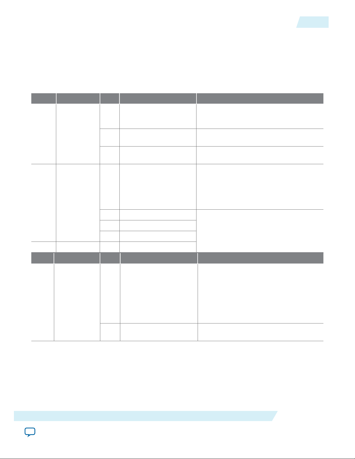
UG-01128
2015.05.04
Setting up PRBS Mode in Arria 10 Devices
Table 8-3: Programming the Hard PCS Registers in Arria 10 Devices
To turn on the PRBS feature in the hard PCS for IP core variations that target an Arria 10 device, you must
program the following hard PCS registers in the order shown, for each of the TX and RX sides. These registers are
not accessible using the 100G Interlaken IP core management interface. You must access these registers through
the Arria 10 transceiver reconfiguration interface of the 100G Interlaken IP core.
Ensure you set these register bits using a read-modify-write register access sequence (per register), to avoid
modifying the other register fields.
TX Register Offset Bits Meaning Action
[2:0] TX test enable Set this field to the value of 3'b100 to enable
the PRBS pattern generator in the
transmitter.
8-5
1 0x6
[3] PRBS width select Set this bit to the value of 0 to specify that
the PRBS width is 64 bits.
[7:6] Enable TX PRBS clock Set this field to the value of 2'b01 to enable
the TX PRBS clock.
[2] Invert TX channels Set this bit to the value of 0 to specify that
the outgoing PRBS be inverted, or set this bit
to the value of 1 to specify that the outgoing
PRBS not be inverted. The default value of
this register field is 0. By default, the
2 0x7
outgoing PRBS is inverted.
[5] Enable PRBS9
[6] Enable PRBS15
Set one of these bits to the value of 1, and the
others to the value of 0, to select the TX
[7] Enable PRBS23
polynomial.
3 0x8 [4] Enable PRBS31
RX Register Offset Bits Meaning Action
[4] Invert RX channels Set this bit to the value of 0 to specify that
the PCS should expect the incoming PRBS
to be inverted, or set this bit to the value of
1 to specify that the PCS should not expect
the incoming PRBS to be inverted. The
1 0xA
default value of this bit is 0. In loopback
mode, you should set this bit to match the
setting in the PRBS transmitter.
100G Interlaken IP Core Test Features
Send Feedback
[7] Enable RX PRBS clock Set this bit to the value of 1 to enable the RX
PRBS clock.
Altera Corporation
Page 91
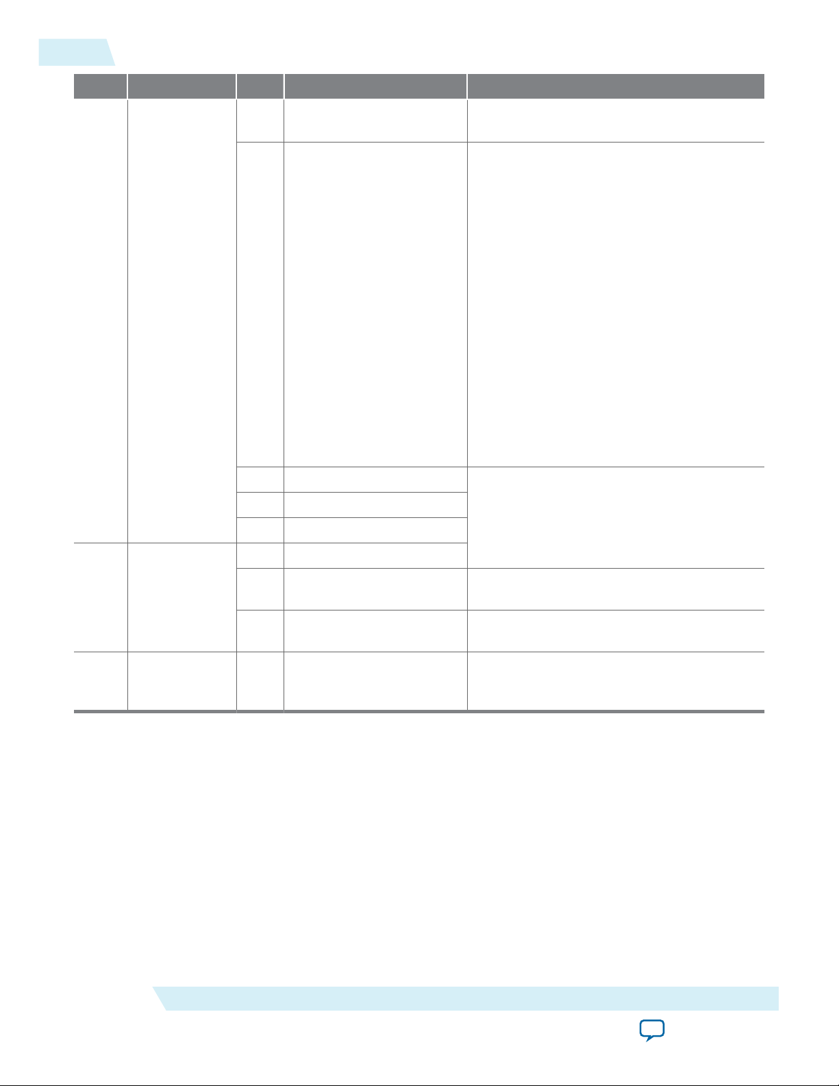
8-6
Setting up PRBS Mode in Arria 10 Devices
RX Register Offset Bits Meaning Action
UG-01128
2015.05.04
2 0xB
[1]
Enable 10G PCS mode Set this bit to the value of 1 to specify the
PCS is in 10G mode.
[3:2] Verifier counter threshold Set this field to the value your design
requires to ensure adequate lead time before
the PRBS checker begins counting PRBS
errors. The field value specifies the wait
time in number of clk_rx_common clock
cycles. A counter begins counting clk_rx_
common clock cycles after the soft reset, and
triggers the start of PRBS checking when the
specified threshold is reached. This field has
the following valid values:
• 2'b00—Specifies the counter threshold
(the wait time) is 127.
• 2'b01—Specifies the counter threshold is
255.
• 2'b10—Specifies the counter threshold is
511.
• 2'b11—Specifies the counter threshold is
1023.
[5]
[6] Enable PRBS15
Enable PRBS9
Set one of these bits to the value of 1, and
the others to the value of 0, to select the
[7] Enable PRBS23
expected polynomial.
[0] Enable PRBS31
[1] Confirm 10G PCS mode Set this bit to the value of 1 to confirm the
3 0xC
PCS is in 10G mode.
[3] PRBS width select Set this bit to the value of 0 to specify that
the PRBS width is 64 bits.
4 0x13F [3:0] RX Deserializer width select Set this field to the value of 4'b1110 to
specify that the data width after deserializa‐
tion is 64 bits.
After you enable the IP core to generate or receive PRBS output, by setting the relevant register field
values for each Interlaken lane, you must perform a soft reset of the transceiver transmitters and receivers.
To perform a soft reset of the transceiver transmitters and receivers, on the 100G Interlaken IP core
management interface, program bit [2] of the 100G Interlaken IP core RESET register at offset 0x13 with
the value of 1. On the following mm_clk cycle, or later, program the bit 0x13[2] with the value of 0 to clear
the reset. After you reset the transceivers and subsequently clear the reset bit, the IP core immediately
begins transmitting PRBS output on the Interlaken link. You can check the receive PRBS status in the
100G Interlaken IP core PRBS status registers (RX_PRBS_DONE, RX_PRBS_ERR, and RX_PRBS_COUNT).
After your testing is complete, you must reset these register bits to their default values and perform the
soft reset to enable normal operation.
Altera Corporation
100G Interlaken IP Core Test Features
Send Feedback
Page 92

UG-01128
2015.05.04
Related Information
• 100G Interlaken IP Core Register Map on page 6-1
Describes the PRBS status registers and the soft reset register.
• Arria 10 Transceiver Reconfiguration Interface Signals on page 5-16
Describes the interface to program the Arria 10 hard PCS registers, including the information you
need to address the registers for each individual lane.
• 100G Interlaken IP Core Management Interface on page 5-13
Describes the interface to program the 100G Interlaken IP core registers, including the RESET register.
• PRBS Generation and Validation on page 8-2
Lists the supported PRBS polynomials.
• Arria 10 Transceiver PHY User Guide
Information about the Arria 10 transceiver reconfiguration interface.
• Arria 10 Transceiver Registers
Information about the Arria 10 transceiver registers.
CRC32 Error Injection
The 100G Interlaken IP core supports the injection of CRC32 errors on the Interlaken link for validation
of the Interlaken link partner's error handling, and for validation of this IP core's error handling in a
loopback configuration. Variations that target an Arria V or Stratix V device require that you first enable
the feature in the hard PCS; variations that target an Arria 10 device do not require this step.
CRC32 Error Injection
8-7
This feature is available if you turn on Include diagnostic features in the 100G Interlaken parameter
editor.
To enable the CRC32 error injection feature in your 100G Interlaken IP core that targets an Arria V or
Stratix V device, set the value of bit [15] of the hard PCS register at offset 0x138 (offset 0xC from the hard
PCS base address of 0x12C) to the value of 1. Ensure you set the register bit using a read-modify-write
register access sequence, to avoid modifying the other register fields. This step is not necessary in
100G Interlaken IP core devices that target an Arria 10 device, because CRC32 error injection is enabled
by default in these variations.
For instructions to program the hard PCS registers in Arria V and Stratix V devices, refer to the Native
PHY IP Core chapter for your target device family and to the Transceiver Reconfiguration Controller
chapter of the Altera Transceiver PHY IP Core User Guide.
After you enable the IP core to inject CRC32 errors in the output to the Interlaken link, you can turn on
the feature using the 100G Interlaken IP core CRC32_ERR_INJECT register. You must maintain each
register bit at the value of 1 for the duration of a Meta Frame, at least, to ensure that the IP core transmits
at least one CRC32 error on the corresponding lane.
After your testing is complete, in Arria V and Stratix V devices, you must reset the hard PCS register bit to
its default value of zero to enable normal operation.
The 100G Interlaken IP core CRC32 error injection feature does not keep a count of the errors injected.
Related Information
100G Interlaken IP Core Register Map on page 6-1
Describes the CRC32_ERR_INJECT register.
Altera Transceiver PHY IP Core User Guide
100G Interlaken IP Core Test Features
Send Feedback
Altera Corporation
Page 93

8-8
CRC24 Error Injection
CRC24 Error Injection
The 100G Interlaken IP core supports the injection of CRC24 errors on the Interlaken link for validation
of the Interlaken link partner's error handling, and for validation of this IP core's error handling in a
loopback configuration.
This feature is available if you turn on Include diagnostic features in the 100G Interlaken parameter
editor.
To force the IP core to inject a bit error in the output to the Interlaken link, you write the value of 1 to bit
[0] of the 100G Interlaken IP core ERR_INJECT register at offset 0x102. This change to the register field
value forces the IP core to inject a single bit error, which will cause one or possibly more CRC24 errors.
Before you can inject a second bit error, you must write the value of 0 to the register. Altera recommends
that you write the value of 1 and then the value of 0 to inject a single bit error, rather than waiting until
you want to inject a second error before writing the value of 0 to clear the register.
UG-01128
2015.05.04
Altera Corporation
100G Interlaken IP Core Test Features
Send Feedback
Page 94

2015.05.04
www.altera.com
101 Innovation Drive, San Jose, CA 95134
Advanced Parameter Settings
9
UG-01128
Subscribe
Advanced users can further customize the 100G Interlaken IP core by modifying hidden parameters that
are not displayed in the 100G Interlaken parameter editor. These parameters can only be modified in the
Verilog RTL instantiation in the generated ilk_core.sv file and the instantiation of the 100G Interlaken IP
core in the top level design file.
The following topics describe the hidden parameters and tell you how to modify their values.
Hidden Parameters on page 9-1
Modifying Hidden Parameter Values on page 9-3
Hidden Parameters
The advanced parameters affect the behavior of the 100G Interlaken MegaCore function.
Altera recommends that you do not modify any RTL parameters that are not listed here. Some
Note:
undocumented modifications might overwrite settings you specify in the parameter editor.
To customize your 100G Interlaken MegaCore function, you can modify parameters to specify the
following properties:
Include Temp Sense on page 9-1
Send Feedback
RXFIFO Address Width on page 9-2
SWAP_TX_LANES and SWAP_RX_LANES (Data Word Lane Swapping) on page 9-2
Include Temp Sense
The Include Temp Sense parameter specifies whether the IP core includes logic to sense the device’s case
temperature. If the value is set to 1, the IP core is configured with internal temperature sensing. If the
value is set to 0, this logic is synthesized away.
This parameter is not available in IP core variations that target an Arria 10 device.
The default value of this parameter is 1.
Related Information
Modifying Hidden Parameter Values on page 9-3
©
2015 Altera Corporation. All rights reserved. ALTERA, ARRIA, CYCLONE, ENPIRION, MAX, MEGACORE, NIOS, QUARTUS and STRATIX words and logos are
trademarks of Altera Corporation and registered in the U.S. Patent and Trademark Office and in other countries. All other words and logos identified as
trademarks or service marks are the property of their respective holders as described at www.altera.com/common/legal.html. Altera warrants performance
of its semiconductor products to current specifications in accordance with Altera's standard warranty, but reserves the right to make changes to any
products and services at any time without notice. Altera assumes no responsibility or liability arising out of the application or use of any information,
product, or service described herein except as expressly agreed to in writing by Altera. Altera customers are advised to obtain the latest version of device
specifications before relying on any published information and before placing orders for products or services.
ISO
9001:2008
Registered
Page 95

Lane N
.
.
.
Lane 2
Lane 1
Lane 0
9-2
RXFIFO Address Width
RXFIFO Address Width
The RXFIFO Address Width parameter specifies the number of bits in the address (offset) of an entry in
the RX Reassembly FIFO. The number of bits is log2 of the depth of this FIFO. Each RX Reassembly FIFO
entry is a 64-bit word.
The default value for the RXFIFO Address Width parameter is 12, specifying this FIFO can hold 2
(==4K) 64-bit words. Adjusting this parameter may affect your ability to close timing for your design.
However, you can adjust this parameter subject to the successful closure of the timing.
Related Information
Modifying Hidden Parameter Values on page 9-3
SWAP_TX_LANES and SWAP_RX_LANES (Data Word Lane Swapping)
The 100G Interlaken IP core supports a lane reversal feature (lane swapping). Lane swapping parameters
determine the order in which blocks are distributed and gathered from the lanes. The 100G Interlaken IP
core provides the following two options for the lane order:
• Straight Lane order. The transmitter sends Interlaken blocks sequentially across the lanes starting with
the top lane, ending with Lane 0. The receiver takes in Interlaken blocks starting with the top lane,
ending with Lane 0.
Figure 9-1: Straight Lane Order
UG-01128
2015.05.04
12
Altera Corporation
• Swapped Lane order. The transmitter sends Interlaken blocks sequentially across the lanes starting
with Lane 0, ending with Lane N. The receiver takes in Interlaken blocks starting with Lane 0, ending
with Lane N.
Advanced Parameter Settings
Send Feedback
Page 96

Lane 1
Lane 2
Lane 0
.
.
.
Lane N
UG-01128
2015.05.04
Modifying Hidden Parameter Values
Figure 9-2: Swapped Lane Order
Two parameters determine lane order:
SWAP_TX_LANES
SWAP_RX_LANES
When a parameter is set to 0, the 100G Interlaken IP core implements the Straight Lane order. When a
parameter is set to 1, the 100G Interlaken IP core implements the Swapped Lane order. The TX and RX
parameters are independent and can be set separately.
9-3
To conform with the Interlaken specification, the default value of SWAP_TX_LANES and SWAP_RX_LANES is
1.
Running traffic with incompatible lane swapping configuration results in CRC24 errors and
Note:
incorrect data at the receiver.
Related Information
Modifying Hidden Parameter Values on page 9-3
Modifying Hidden Parameter Values
To modify the value of a hidden parameter, you must edit one or more generated files. Every time you
regenerate the 100G Interlaken IP core, the files are overwritten and you must edit them again.
Table 9-1: Files to Edit to Modify the Value of a Hidden Parameter
In each entry, the first file controls the RTL parameter value for synthesis, and the second file controls the RTL
parameter value for simulation.
Parameter Arria 10 Variations Other Variations
RXFIFO_ADDR_WIDTH
<instance name>/synth/
<instance name>.v
<instance name>/sim/
<instance name>.v
<instance name>.v
<instance name>_ sim/<instance name>.v
Advanced Parameter Settings
Send Feedback
Altera Corporation
Page 97

9-4
Modifying Hidden Parameter Values
Parameter Arria 10 Variations Other Variations
UG-01128
2015.05.04
SWAP_TX_LANES
<instance name>/ilk_core_
<version>/synth/ilk_core.sv
SWAP_RX_LANES
<instance name>/ilk_core_
<version>/sim/ilk_core.sv
INCLUDE_TEMP_SENSE —
<instance name>/ilk_core.sv
<instance name>_sim/ilk_core.sv
Altera Corporation
Advanced Parameter Settings
Send Feedback
Page 98

Out-of-Band Flow Control in the
TX Out-of-Band
Flow Control
RX Out-of-Band
Flow Control
tx.fc_clk
tx.fc_sync
tx.fc_data
rx.fc_clk
rx.fc_sync
rx.fc_data
double_fc_clk
double_fc_arst
ena_status
lane_status
link_status
calendar
status_update
lane_status
link_status
status_error
calendar
calendar_update
calendar_error
Out-of-Band
Flow Control
Application
Signals
Out-of-Band
Flow Control
Interface
sys_clk
sys_arst
www.altera.com
101 Innovation Drive, San Jose, CA 95134
100G Interlaken MegaCore Function
2015.05.04
UG-01128
Subscribe
The 100G Interlaken MegaCore function includes logic to provide the out-of-band flow control function‐
ality described in the Interlaken Protocol Specification, Revision 1.2, Section 5.3.4.2. This optional feature is
intended for applications that require transmission rate control.
Figure 10-1: Out-of-Band Flow Control Block Interface
This figure lists the signals on the four interfaces of the out-of-band flow control block.
Send Feedback
10
The out-of-band flow control block is provided as two separate modules that can be stitched to the
100G Interlaken IP core and user logic. You can optionally instantiate these blocks in your own custom
logic. To enable the use of these out-of-band modules, the signals on the far left side of the figure must be
connected to user logic, and the signals on the far right side of the figure should be connected to the
complementary flow control blocks of the Interlaken link partner.
You must connect the out-of-band flow control receive and transmit interface signals to device pins.
Out-of-Band Flow Control Block Clocks on page 10-2
TX Out-of-Band Flow Control Signals on page 10-2
RX Out-of-Band Flow Control Signals on page 10-4
©
2015 Altera Corporation. All rights reserved. ALTERA, ARRIA, CYCLONE, ENPIRION, MAX, MEGACORE, NIOS, QUARTUS and STRATIX words and logos are
trademarks of Altera Corporation and registered in the U.S. Patent and Trademark Office and in other countries. All other words and logos identified as
trademarks or service marks are the property of their respective holders as described at www.altera.com/common/legal.html. Altera warrants performance
of its semiconductor products to current specifications in accordance with Altera's standard warranty, but reserves the right to make changes to any
products and services at any time without notice. Altera assumes no responsibility or liability arising out of the application or use of any information,
product, or service described herein except as expressly agreed to in writing by Altera. Altera customers are advised to obtain the latest version of device
specifications before relying on any published information and before placing orders for products or services.
ISO
9001:2008
Registered
Page 99

10-2
Out-of-Band Flow Control Block Clocks
Related Information
Interlaken Protocol Specification, Revision 1.2
Out-of-Band Flow Control Block Clocks
Table 10-1: 100G Interlaken MegaCore Function Out-of-Band Flow Control Block Clocks
UG-01128
2015.05.04
Clock Name Interface Direction Recommende
d Frequency
(MHz)
RX fc_clk RX Out-of-
Input 100 Clocks the incoming out-of-band flow control
band
TX fc_clk TX Out-of-
Output 100 Clocks the outgoing out-of-band flow control
band
sys_clk RX
Input 200 Clocks the outgoing calendar and status informa‐
Application
Description
interface signals described in the Interlaken
specification. This clock is received from an
upstream TX out-of-band flow control block
associated with the Interlaken link partner. The
recommended frequency for the RX fc_clk clock
is 100 MHz, which is the maximum frequency
allowed by the Interlaken specification.
interface signals described in the Interlaken
specification. This clock is generated by the
out-of-band flow control block and sent to a
downstream RX out-of-band flow control block
associated with the Interlaken link partner. The
frequency of this clock must be half the frequency
of the double_fc_clk clock. The recommended
frequency for the TX fc_clk clock is 100 MHz,
which is the maximum frequency allowed by the
Interlaken specification.
tion on the application side of the block. The
frequency of this clock must be at least double the
frequency of the RX input clock fc_clk.
Therefore, the recommended frequency for the
sys_clk clock is 200 MHz.
double_
fc_clk
TX
Application
Input 200 Clocks the incoming calendar and status informa‐
TX Out‑of‑Band Flow Control Signals
The transmit out-of-band flow control interface receives calendar and status information, and transmits
flow-control clock, data, and sync signals. The TX Out-of-Band Flow Control Interface Signals table
describes the transmit out-of-band flow control interface signals specified in the Interlaken Protocol
Altera Corporation
tion on the application side of the block. The
frequency of this clock must be double the
frequency of the TX output clock fc_clk.
Therefore, the recommended frequency for the
double_fc_clk clock is 200 MHz.
Out-of-Band Flow Control in the 100G Interlaken MegaCore Function
Send Feedback
Page 100
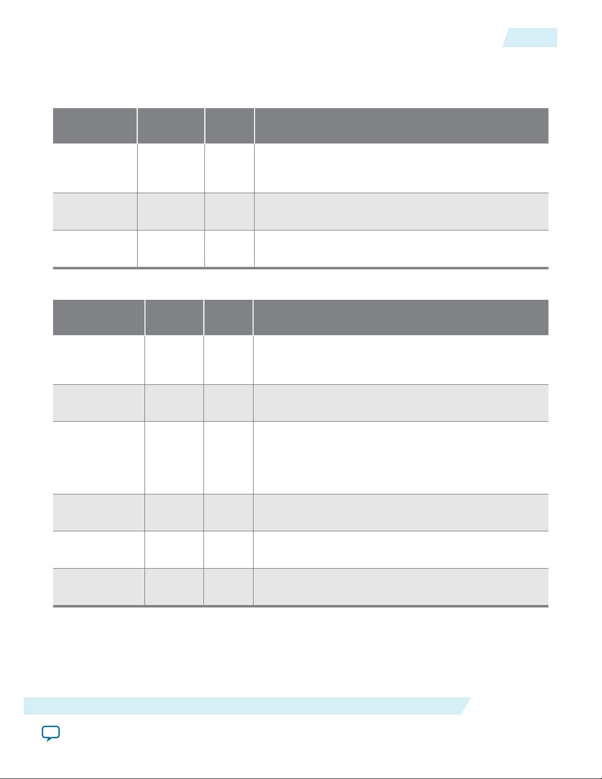
UG-01128
2015.05.04
Specification, Revision 1.2. The TX Out-of-Band Flow Control Block Signals for Application Use table
describes the signals on the application side of the TX out-of-band flow control block.
Table 10-2: TX Out-of-Band Flow Control Interface Signals
TX Out‑of‑Band Flow Control Signals
10-3
Signal Name Direction Width
(Bits)
fc_clk Output 1 Output reference clock to an upstream out-of-band RX block.
Description
Clocks the fc_data and fc_sync signals. You must connect
this signal to a device pin.
fc_data Output 1 Output serial data pin to an upstream out-of-band RX block.
You must connect this signal to a device pin.
fc_sync Output 1 Output sync control pin to an upstream out-of-band RX block.
You must connect this signal to a device pin.
Table 10-3: TX Out-of-Band Flow Control Block Signals for Application Use
Signal Name Direction Width
(Bits)
double_fc_clk Input 1 Reference clock for generating the flow control output clock
fc_clk. The frequency of the double_fc_clk clock must be
Description
double the intended frequency of the TX fc_clk output clock.
double_fc_
arst
Input 1 Asynchronous reset for the out-of-band TX block.
ena_status Input 1 Enable transmission of the lane status and link status to the
downstream out-of-band RX block. If this signal is asserted,
the lane and link status information is transmitted on fc_data.
If this signal is not asserted, only the calendar information is
transmitted on fc_data.
lane_status Input Number
of Lanes
link_status Input 1 Link status to be transmitted to a downstream out-of-band RX
Lane status to be transmitted to a downstream out-of-band RX
block if ena_status is asserted. Width is the number of lanes.
block if ena_status is asserted.
calendar Input 16 Calendar status to be transmitted to a downstream out-of-band
RX block.
Related Information
Interlaken Protocol Specification, Revision 1.2
Out-of-Band Flow Control in the 100G Interlaken MegaCore Function
Altera Corporation
Send Feedback
 Loading...