

Page 1

TUE-T112P
EN
MOBILE TV TUNER SYSTEM
• OWNER'S MANUAL
• BEDIENUNGSANLEITUNG
•MODE D'EMPLOI
• MANUAL DE OPERACIÓN
• ISTRUZIONI PER L'USO
• ANVÄNDARHANDLEDNING
ALPINE ELECTRONICS, INC.
Tokyo office: 1-1-8 Nishi Gotanda,
Shinagawa-ku,
Tokyo 141-8501, Japan
Tel.: (03) 3494-1101
ALPINE ELECTRONICS OF AMERICA, INC.
19145 Gramercy Place, Torrance,
California 90501, U.S.A.
Tel.: 1-800-ALPINE-1 (1-800-257-4631)
ALPINE ELECTRONICS OF CANADA, INC.
Suite 203, 7300 Warden Ave. Markham,
Ontario L3R 9Z6, Canada
Tel.: 1-800-ALPINE-1 (1-800-257-4631)
Please read before using this equipment.
Lesen Sie diese Bedienungsanleitung bitte
vor Gebrauch des Gerätes.
Veuillez lire avant d'utiliser cet appareil.
Léalo antes de utilizar este equipo.
Si prega di leggere prima di utilizzare
l'attrezzatura.
Innan du använder utrustningen bör du läsa
igenom denna användarhandledning.
ALPINE ELECTRONICS OF AUSTRALIA PTY. LTD.
6-8 Fiveways Boulevarde Keysborough,
Victoria 3173, Australia
Tel.: (03) 9769-0000
ALPINE ELECTRONICS GmbH
Frankfurter Ring 117 80807 Munich, Germany
Via C. Colombo 8, 20090 Trezzano Sul Naviglio
Tel.: 089-32 42 640
ALPINE ITALIA S.p.A.
MI, Italy
Tel.: 02-48 47 81
ALPINE ELECTRONICS (BENELUX) GmbH
Leuvensesteenweg 510-B6,
1930 Zaventem, Belgium
Tel.: 02-725 1315
ALPINE ELECTRONICS FRANCE S.A.R.L.
98, Rue De La Belle Etoile, Z.I. Paris Nord Il
B.P. 50016 F-95945, Roissy, Charles De Gaulle
ALPINE ELECTRONICS OF U.K., LTD.
13 Tanners Drive, Blakelands, Milton Keynes
ALPINE ELECTRONICS DE ESPAÑA, S.A.
Portal De Gamarra 36, Pabellón 32
01013 Vitoria (Alava)-Apdo. 133, Spain
(RCS PONTOISE B 338 101 280)
Cedex, France
Tel.: 01-48 63 89 89
MK14 5BU, U.K.
Tel.: 01908-61 15 56
Tel.: 34-45-283588
DE
FR
ES
IT
SE
Page 2
Contents
Operating instructions
WARNING
WARNING ......................................... 2
CAUTION...........................................2
PRECAUTIONS.................................3
Controls and Features
TV tuner unit ...................................... 4
Remote controller............................... 5
Remote Controller Battery
Replacement......................................6
Basic Operations
Watching television............................7
Storing channels in memory (auto
memory)............................................. 8
Setting the channel selection.............9
Watching playback of external
component ....................................... 10
Adjusting the headphone volume..... 11
Installation instructions
Installation and Connections
WARNING ....................................... 16
CAUTION ........................................ 16
PRECAUTIONS............................... 17
Before installing ............................... 17
Installing the antenna ...................... 20
Electrical Connections
Typical Connections ........................ 21
Troubleshooting
Maintenance
Information
In Case of Difficulty..........................13
Specifications................................... 14
1-EN
Page 3
WARNING
WARNI NG
CAUTION
WARNING
This symbol means important instructions.
Failure to heed them can result in serious
injury or death.
BE SURE TO INSTALL THE MONITOR ON TOP OF
THE DASHBOARD TO PREVENT IT FROM OBSTRUCTING VISIBILITY.
Any function that requires your prolonged attention
should only be performed after coming to a complete stop. Always stop the vehicle in a safe location
before performing these functions. Failure to do so
may result in an accident.
DO NOT DISASSEMBLE OR ALTER.
Doing so may result in an accident, fire or electric
shock.
USE THIS PRODUCT FOR MOBILE 12V APPLICATIONS.
Use for other than its designed application may result in fire, electric shock or other injury.
CAUTION
This symbol means important instructions.
Failure to heed them can result in injury or
material property damage.
HALT USE IMMEDIATELY IF A PROBLEM APPEARS.
Failure to do so may cause personal injury or damage to the product. Return it to your authorized Alpine dealer or the nearest Alpine Service Center for
repairing.
DO NOT MIX NEW BATTERIES WITH OLD BATTERIES. INSERT WITH THE CORRECT BATTERY POLARITY.
When inserting the batteries, be sure to observe
proper polarity (+ and -) as instructed. Rupture or
chemical leakage from the battery may cause fire or
personal injury.
KEEP SMALL OBJECTS SUCH AS BATTERY OUT OF
THE REACH OF CHILDREN.
Swallowing them may result in serious injury. If
swallowed, consult a physician immediately.
USE THE CORRECT AMPERE RATING WHEN REPLACING FUSES.
Failure to do so may result in fire or electric shock.
2-EN
Page 4
PRECAUTIONS
PRECAUTIONS
Temperature
Be sure the temperature inside the vehicle is between +45°C (+113°F) and 0°C (+32°F) before
turning your unit on.
Fuse Replacement
When replacing the fuse(s), the replacement must be
of the same amperage as shown on the fuse holder.
If the fuse(s) blows more than once, carefully check
all electrical connections for shorted circuitry. Also
have your vehicle's voltage regulator checked.
Maintenance
If you have problems, do not attempt to repair the
unit yourself. Return it to your Alpine dealer or the
nearest Alpine Service Station for servicing.
Installation Location
Make sure the TUE-T112P will not be exposed to:
• Direct sun and heat
• High humidity
• Excessive dust
• Excessive vibrations
3-EN
Page 5
Controls and Features
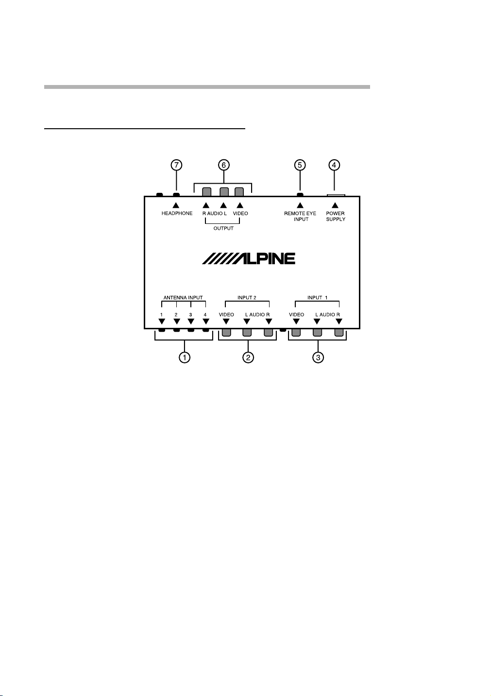
TV tuner unit
A ANTENNA INPUT jacks (for con-
necting the diversity antenna)
B INPUT 2 jacks
•VIDEO
•AUDIO L
•AUDIO R
C INPUT 1 jacks
•VIDEO
•AUDIO L
•AUDIO R
D POWER SUPPLY connector
E REMOTE EYE INPUT
4-EN
F OUTPUT jacks
•VIDEO
•AUDIO L
•AUDIO R
G HEADPHONE jack
Page 6
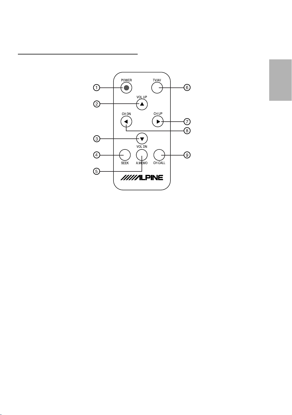
Remote controller
A POWER button (7)
B VOL UP (Headphone volume up)
button (11)
C VOL DN (Headphone volume
down) button (11)
D SEEK button (9)
E A.MEMO (Auto memory) button
(8)
F TV/AV button (7, 8, 9, 10)
G CH UP (Channel up) button (7)
H CH DN (Channel down) button (7)
I CH CALL button (10)
Before using the remote controller:
• Aim the remote controller directly at
the remote sensor on the color monitor. Make sure there is no obstacle
in between.
• Do not expose the remote sensor to
strong light (direct sunlight or artificial lighting).
5-EN
Page 7
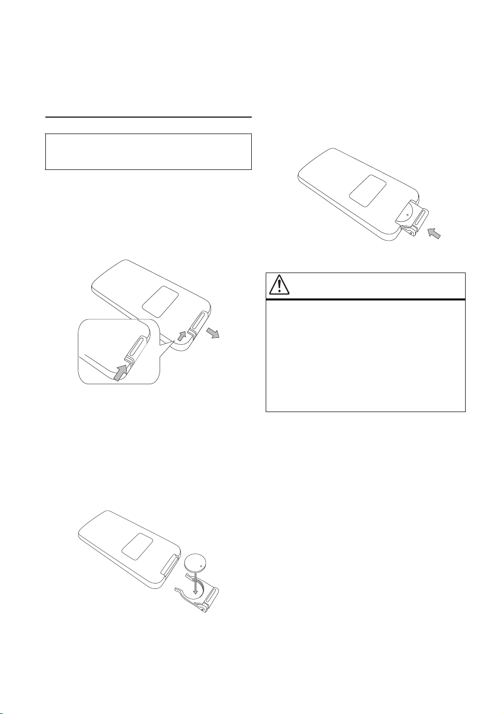
Remote Controller
Battery Replacement
Battery type: CR2025 battery or
equivalent.
1 Opening the battery case
Slide out the battery cover while
firmly pressing in the direction of the
arrow.
2 Replacing the battery
Put the battery in the case with the
(+) indication upward as shown in
the illustration.
• Placing a battery in backwards way may cause a
malfunction.
3 Closing the cover
Slide the cover as illustrated until a
click is heard.
WAR N I N G
WARNING
DO NOT OPERATE ANY FUNCTION THAT
TAKES YOUR ATTENTION AWAY FROM
SAFELY DRIVING YOUR VEHICLE.
Any function that requires your prolonged
attention should only be performed after
coming to a complete stop. Always stop the
vehicle in a safe location before performing
these functions. Failure to do so may result in
an accident.
6-EN
Page 8
Basic Operations
Watching television
Preparation
Before operating the system, make
sure that all external components
are correctly connected and
installed. For connecting the external
components, refer to the instructions
and the installations supplied with
the external components.
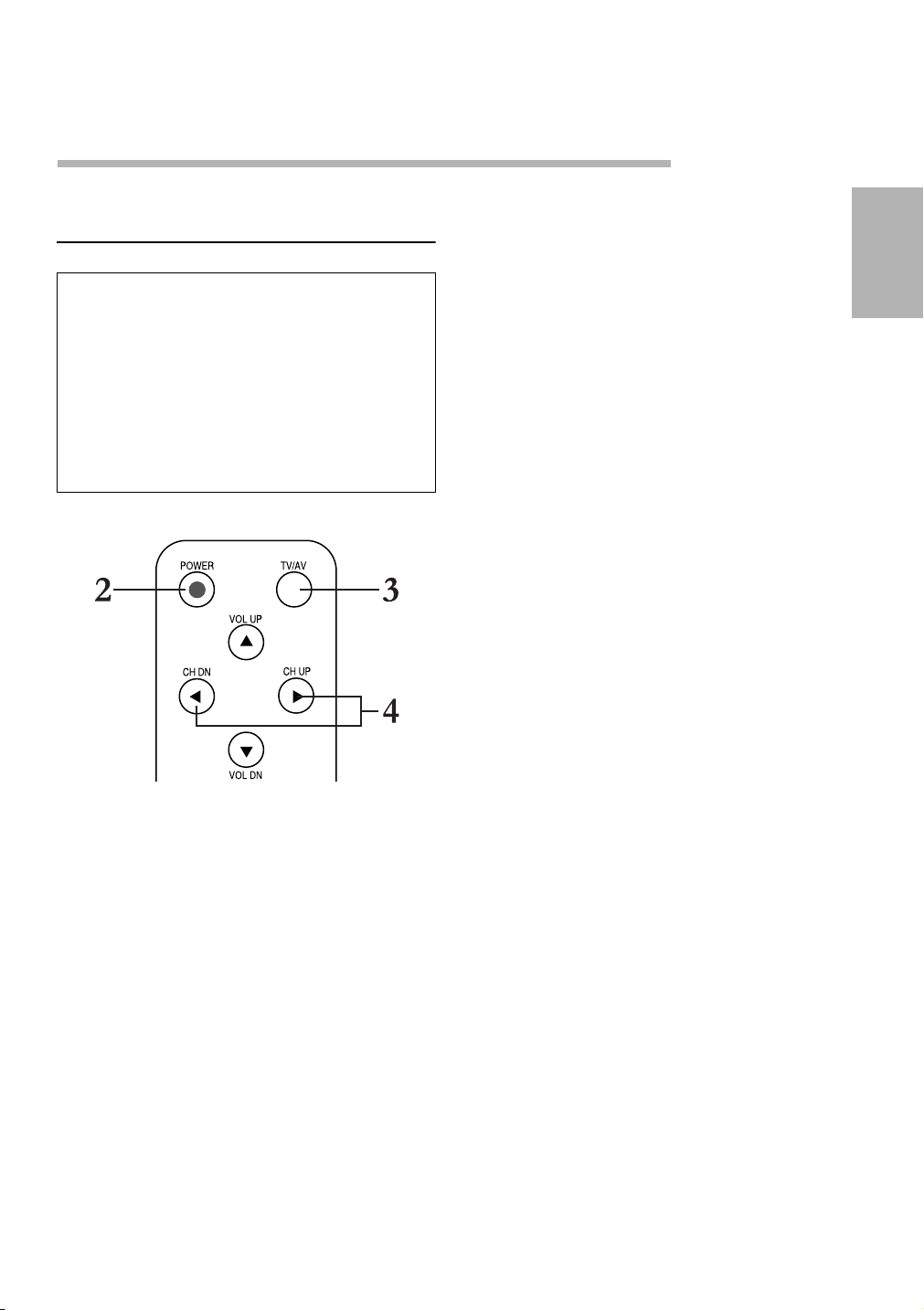
3 Select TV as the input source.
Press the TV/AV button on the remote controller repeatedly to select
TV.
4 Select the channel you want to
watch.
Press the CH UP or CH DN on the
remote controller to change the
channels.
If the channel selection is set to
“AUTO” (See page 9.)
You can select only the channels
preset by the auto memory function. (See page 8.)
If the channel selection is set to
“MANUAL” (See page 9.)
You can select all the channels.
(Channel coverage: VHF channels
1 to 12, UHF channels 21 to 69)
Remote controller
1 If the system is connected to the
parking brake system:
Engage the parking brake and turn
on the engine.
If the system is not connected to the
parking brake system:
Turn on the engine.
2 Turn on the power.
Press the POWER button on the remote controller.
5 Adjust the volume level on the car
receiver.
To turn off the power
Press the POWER button on the remote controller.
• Turning off the engine will also turn
off the TV tuner system.
7-EN
Page 9

Storing channels in
memory (auto memory)
When scanning is over, the screen
shows the TV program of the smallest
channel number in memory.
The auto memory function picks up the
TV broadcast signals in the area where
you are and stores them automatically
in memory.
NOTES
• TV stations with weak signals are not be picked
up, therefore not being stored in memory.
• If you drive from one broadcasting area to anoth-
er, the stored channels will not be tuned in. In this
case, perform the auto memory function again to
store the stations in another area.
1 Select TV as the input source.
Press the TV/AV button on the remote controller repeatedly to select
TV.
2 Start scanning TV broadcast sig-
nals.
Press the A.MEMO button on the
remote controller.
The auto memory function starts
and TV broadcast signals are
picked up and stored in memory
while scanning.
8-EN
Page 10

Setting the channel
selection
You can set the channel selection
method either to select only the receivable channels in memory or to select all
the channels.
Remember that if you want to select
only the receivable channels, you must
store the channels first. To store them,
see page 8.
AUTO: Only the receivable chan-
nels stored in memory can
be selected. When you
change the channel, channel number and “AUTO”
appear on the screen for a
while.
MANUAL: All the channels can be se-
lected. (Channel coverage:
VHF channels 1 to 12,
UHF channels 21 to 69)
Remote controller
1 Select TV as the input source.
Press the TV/AV button on the remote controller repeatedly to select
TV.
2 Set the channel selection to
“AUTO” or “MANUAL.”
Press the SEEK button on the re-
mote controller.
Each time you press the button, the
channel selection alternates between “AUTO” and “MANUAL.”
9-EN
Page 11

Watching playback of
external component
You can connect up to 2 external video
components to the TV tuner unit.
AUX1
Ex: When AUX1 is selected
2 Play back the external component.
To watch the playback, first follow steps
1 and 2 on page 7, then perform the following steps.
Remote controller
1 Select the input source.
Press the TV/AV button on the remote controller to select the input
source you want.
Each time you press the button, the
input source changes as follows:
TV
AUX1
AUX2
To operate the external components, refer to the manuals of the
connected components.
3 Adjust the volume level on the car
receiver.
To check the current input source
Press the CH CALL button on the remote controller.
The current input source name appears
on the screen for 3 seconds.
To turn off the power
Press the POWER button on the remote controller.
• Turning off the engine will also turn
off the TV tuner system.
NOTES
• When you watch the screen aslant, the picture
might not be clear. This is not a malfunction. The
finest picture can be seen when you watch the
screen straight.
The selected input source name
also appears on the screen for 3
seconds.
10-EN
Page 12

Adjusting the headphone
volume
Press and hold the VOL UP or VOL DN
button to adjust the headphone volume.
You can adjust the volume level between 0 and 35.
VOL DN
and
VOL UP
The headphone volume level appears
on the screen.
NOTE
This adjustment is only for the connected headphones but not for the speakers in the car. When adjusting the speaker volume, adjust it by using the car
receiver.
11-EN
Page 13

Maintenance
To prevent damage to the system exterior
• Do not apply pesticides, benzine,
thinner or other volatile substances
to the unit.
The cabinet surface primarily consists of plastic materials.
• Do not wipe with benzine, thinner or
similar substances because this will
result in discoloration or removal of
the paint.
• When a cloth with a cleansing chemical is used, follow the caution points:
- Do not leave the unit in contact with
rubber or vinyl products for long
periods of time.
- Do not use cleansers which have
polishing granules because this
could damage the surface of the
unit.
CAUTION
If water drops or similar wet substances
get inside of the monitor via the liquid
crystal panel surface, it may cause a
malfunction.
Clean dirt by wiping lightly with a
soft cloth
When the unit is very dirty, wipe with a
well-wrung cloth dipped in a kitchen
cleanser (neutral) thinned by water and
then go over the same surface with a
dry cloth.
(Since there is the possibility of water
drops getting inside of the unit, do not
directly apply cleanser to the surface.)
12-EN
Page 14

Information
In Case of Difficulty
If you encounter a problem, please
review the items in the following
checklist. This guide will help you
isolate the problem if the unit is at
fault. Otherwise, make sure the rest
of your system is properly connected
or consult your authorized Alpine
dealer.
No power supplied.
• Vehicle's ignition is off.
- Turn the ignition on.
• No fuse or blown fuse.
- Check the cause and replace the fuse.
• Incorrect connections.
- Check connection and remedy.
• Vehicle's battery is weak.
- Check the voltage of vehicle's battery.
Remote control does not work.
• Battery is worn out.
- Replace battery.
• Incorrect battery insertion.
- Insert battery correctly.
• Remote control does not point remote control sensor.
- Operate remote control so that it faces the sen-
sor.
• Remote control sensor or remote control transmitter window is dirty.
- Clean remote control sensor or transmitter win-
dow.
Picture not clear or noises appear.
• Poor signal strength.
• Out of service area of station being received.
- Check by moving car in other location.
• Fluorescent tube is exhausted.
- Replace the fluorescent tube.*
No picture obtained.
• Mode switch is not set to a desired mode.
- Select desired mode by pressing TV/NAV./
VIDEO button.
• Temperature inside car is high.
- Lower the temperature.
• Poor connections between monitor and tuner.
- Check connections.
Dots or stripes appear on picture.
• Affected from neon sign, high voltage line, amateur radio transmission, cars, etc.
- Move car to a location free from interference.
Double or triple pictures or rolling
picture appear.
• Signals are reflected by mountain or buildings
near car.
- Move car to other locations. Adjust location, di-
rection and height of antenna.
Noises appear in car radio.
• High frequency signals from TV are received by
car radio.
- Keep away antenna leads and other wire leads
from TV.
13-EN
Page 15

Too much voice noise is heard.
• TV area is improper.
- Confirm the setting for a TV area.
Specifications
TV TUNER UNIT
Audio interruption function does not
work in combination with navigation
system.
• TV channel 56 is received.
- Switch channel other than 56.
• Poor connection of guide control input cord.
- Connect guide control cord of navigation securely.
Channel display is incorrect.
• The field strength is low.
- Move the car to other location and check it
again.
Picture becomes whitish.
• Located under a TV tower.
- Move the car to other location to use it.
- If you want to use in that location, turn the TV
antenna's booster switch to off position.
* The fluorescent tube replacement is not free of
charge even within the warranty period, for the
tube is an article of consumption.
TV/AV button does not work well.
• Even if pressing the TV/AV button, TV area setup
menu screen does not come out.
- Press the button after changing TV band to TV1
or TV2. It cannot be operated if it is TV3.
TV area cannot be changed.
• Even if trying to change the TV area, it stays to be
the former one.
- Change the TV area again, and press and hold
the TV/AV button at least 1 second.
Input
Antenna:........................ Mini-jack × 4
Video: .................RCA pin × 2 circuits
1 V(p-p), 75 Ω
Audio: .................RCA pin × 2 circuits
0.5 V(rms)
Remote in:..........Stereo mini-jack × 1
Output
Video: ...................RCA pin × 1 circuit
1 V(p-p), 75 Ω
Audio: ...................RCA pin × 1 circuit
0.5 V(rms)
Headphone:........Stereo mini-jack × 1
0 mW to 15 mW per channel output
into 32 Ω
Dimensions (W × H × D):
.......... 163 mm × 28.5 mm × 120 mm
Mass: .......................................0.6 kg
GENERAL
Channel coverage:.....VHF: ch 1 – 12
UHF: ch 21 – 69
Power Requirement
Operating Voltage: ..........DC 14.4 V
(11 V to 16 V allowance)
Grounding System:.. Negative ground
Allowable Operating Temperature:
..................................... 0°C to +40°C
Allowable Storage Temperature:
................................. –20°C to +80°C
Design and specifications subject to
change without notice.
14-EN
Page 16

DIVERSITY ANTENNA
Output impedance
......................75 ohms, 3.5 ø mini-jack
Operating Voltage
............................DC14.4V (11 to 16V)
Operating Current .......................50mA
Operating Temperature Range
.....................................–10°C ~ +60°C
15-EN
Page 17

Installation and Connections
Before installing or connecting the
unit, please read the following and
pages 2 and 3 of this manual thoroughly for proper use.
WARNING
WARNING
MAKE THE CORRECT CONNECTIONS.
Failure to make the proper connections may result in
fire or product damage.
USE ONLY IN CARS WITH A 12 VOLT NEGATIVE
GROUND.
(Check with your dealer if you are not sure.) Failure
to do so may result in fire, etc.
BEFORE WIRING, DISCONNECT THE CABLE FROM
THE NEGATIVE BATTERY TERMINAL.
Failure to do so may result in electric shock or injury
due to electrical shorts.
DO NOT SPLICE INTO ELECTRICAL CABLES.
Never cut away cable insulation to supply power to
other equipment. Doing so will exceed the current
carrying capacity of the wire and result in fire or
electric shock.
DO NOT USE BOLTS OR NUTS IN THE BRAKE OR
STEERING SYSTEMS TO MAKE GROUND CONNECTIONS.
Bolts or nuts used for the brake or steering systems
(or any other safety-related system), or tanks should
NEVER be used for installation or ground connections. Using such parts could disable control of the
vehicle and cause fire, etc.
KEEP SMALL OBJECTS SUCH AS BATTERY OUT OF
THE REACH OF CHILDREN.
DO NOT INSTALL IN LOCATIONS WHICH MIGHT
HINDER VEHICLE OPERATION, SUCH AS THE
STEERING WHEEL OR GEARSHIFT.
Doing so may obstruct forward vision or hamper
movement etc. and results in serious accidents.
CAUTION
CAUTION
HAVE THE WIRING AND INSTALLATION DONE BY
EXPERTS.
The wiring and installation of this unit requires special technical skill and experience. To ensure safety,
always contact the dealer where you purchased this
product to have the work done.
USE SPECIFIED ACCESSORY PARTS AND INSTALL
THEM SECURELY.
Be sure to use only the specified accessory parts.
Use of other than designated parts may damage this
unit internally or may not securely install the unit in
place. This may cause parts to become loose resulting in hazards or product failure.
ARRANGE THE WIRING SO IT IS NOT CRIMPED OR
PINCHED BY A SHARP METAL EDGE.
Route the cables and wiring away from moving
parts (like the seat rails) or sharp or pointed edges.
This will prevent crimping and damage to the wiring. If wiring passes through a hole in metal, use a
rubber grommet to prevent the wire’s insulation
from being cut by the metal edge of the hole.
DO NOT INSTALL IN LOCATIONS WITH HIGH MOISTURE OR DUST.
Avoid installing the unit in locations with high incidence of moisture or dust. Moisture or dust that penetrates into this unit may result in product failure.
Swallowing them may result in serious injury. If
swallowed, consult a physician immediately.
16-EN
Page 18

PRECAUTIONS
PRECAUTIONS
Before installing
• Be sure to disconnect the cable from the (–) battery post
before installing your TUE-T112P. This will reduce any
chance of damage to the unit in case of a shortcircuit.
• Be sure to connect the color coded leads according to
the diagram. Incorrect connections may cause the unit
to malfunction or damage the vehicle's electrical system.
• When making connections to the car’s electrical sys-
tem, be aware of the factory installed components (e.g.
on-board computer). Do not tap into these leads to provide power for this unit. When connecting the
TUE-T112P to the fuse box, make sure the fuse for the
intended circuit of the TUE-T112P has the appropriate
amperage. Failure to do so may result in damage to the
unit and/or the vehicle. When in doubt, consult your
ALPINE dealer.
• The TUE-T112P uses female RCA-type jacks for con-
nection to other units (e.g. amplifier) having RCA connectors. You may need an adaptor to connect other
units. If so, please contact your authorized ALPINE
dealer for assistance.
• The diversity antenna supplied with
this unit is designed specifically for
use with the ALPINE mobile color
monitor system. (It cannot be connected to the car radio.)
• Do not rub the antenna or the antenna’s cable with alcohol, benzine,
thinner, gasoline or other volatile
substances.
• Attach to the inside of the car window glass.
• Be sure to wipe the window surface
where the antenna will be attached
with a clean cloth to remove moisture, dirt, dust, wax, oil or other substances. (If there is moisture, oil or
other wet substances on the attachment surface, the attachment tape
will not stick well and easily come
off.)
IMPORTANT
Please record the serial number of your unit
in the space provided below and keep it as a
permanent record. The serial number plate
is located on the bottom of the unit.
SERIAL NUMBER: ___________________
INSTALLATION DATE: __________________
INSTALLATION TECHNICIAN: __________
PLACE OF PURCHASE: _______________
• Be sure to attach the antenna so that
the adhesive surface is not on glass
heating wires or glass antenna
wires.
• Identify the exact attachment location and confirm that the antenna will
not interfere with a heating wire,
glass antenna or wiper motor.
17-EN
Page 19

Antenna element
Ground wire
Connected to
metal section on
the vehicle
Loading section
Antenna base
Antenna element
Ground wire
Connected to
metal section on
the vehicle
Headphone
(not supplied)
Monitor, etc.
RL
1
HEADPHONE
ANTENNA INPUT INPUT 2
234
VIDEO Remote EYE
AUDIO
OUTPUT
VIDEO L RAUDIO L RAUDIOVIDEO1
INPUT
INPUT 1
POWER
SUPPLY
18-EN
DVD Player, etc.
Page 20

When the attachment surface overlaps with a heating wire or glass antenna
a For the antenna base
Attach the antenna base to the location where it does not overlap
with a heating wire or glass antenna.
Antenna base
Antenna element’s end
Take off the
adhesive tape
When the attachment surface overlaps with an electrode
Take off the
adhesive tape
b For the loading section
Attach the loading section to the location where it does not overlap
with a heating wire or glass antenna.
Loading section
Take off the
adhesive tape
c For the antenna element’s end
Attach the antenna element’s end
to the location where it does not
overlap with a heating wire or glass
antenna.
Attach the antenna to either the left or
right of the electrode.
Electrode
Heating
wires
When the attachment surface interferes with a rear wiper motor or a
high-mounted brake light
Move the antenna’s attachment position upwards to avoid interference.
19-EN
Page 21

Installing the antenna
1 Remove the cover paper from the
antenna base tape and attach to the
surface.
2 Remove the cover paper from the
loading section tape and attach to
the surface.
3 Remove the cover paper from the
antenna element’s end tape and attach to the surface.
Antenna element’s end
Loading section
20-EN
Antenna base
Page 22

Electrical Connections
To prevent short circuits, we recommend that you disconnect the battery’s
negative terminal and make all electrical connections before installing the
unit. If you are not sure how to install
this unit correctly, have it installed by a
qualified technician.
NOTE
This unit is designed to operate on 12 V DC, NEGATIVE ground electrical systems. If your vehicle
does not have this system, a voltage inverter is required, which can be purchased at ALPINE IN-CAR
ENTERTAINMENT.
• Replace the fuse with one of the specified ratings.
If the fuse blows frequently, consult your ALPINE
IN-CAR ENTERTAINMENT.
Typical Connections
Before connecting:
• Check the wiring in the vehicle
carefully. Incorrect connection
may cause serious damage to this
unit.
1 Connect the colored leads of the
power cord to the car battery, remote control and parking brake in
the following sequence.
1 Black: ground
2 Yellow: to car battery (constant
12 V)
3 Red: to an accessory terminal
4 White with brown stripe: to re-
mote control lead of monitor
5 Yellow with blue stripe: to park-
ing brake or metallic body or
chassis of the car
2 Finally connect the wiring harness
to the unit.
21-EN
Page 23

Black
Yellow
*1: Before checking the
operation of this unit
prior to installation, this
lead must be connected, otherwise power
cannot be turned on.
* Not included
*
1
To metallic body or chassis of
1
the car
*1
3A
To a live terminal in the fuse
block connecting to the car bat-
2
tery (bypassing the ignition
switch)
*
Ignition switch
with this unit
Red
White with brown
stripe
Yellow with blue
stripe
To an accessory terminal in the
3
fuse block
To remote control lead of monitor
4
To parking brake or metallic body or chassis of the car
5
Fuse block
22-EN
Page 24

Troubleshooting
The fuse blows.
• Are the yellow and black leads connected correctly?
Power cannot be turned on.
• Is the red lead connected?
Picture does not come on screen.
• Is the parking brake engaged?
• Is the yellow, blue striped cord correctly connected?
Picture does not appear clearly.
• Is the color monitor installed at the right angle?
23-EN
 Loading...