

Page 1

Alpha Industrial Power
Spill Control Barrier System
Installation Manual
Battery Acid Spill ControlBarrier
with Acidsafe Floor Coating
Battery AcidSpillControlBarrier
without AcidsafeFloor Coating
AlphaIndustrial Power
1075Satellite Blvd,Suite100 678-475-3995
Suwanee, GA30024 800-996-6104
www.alpha.com
Page 2

Alpha Industrial Power Spill Control Barrier System
Spill Control Barrier System
Installation Manual
TABLEOFCONTENTS
1. Introduction .......................................................................... 1
2. Safety Precautions............................................................... 2
3. Initial Conditions .................................................................. 4
4. Floor Preparation................................................................. 5
5. Barrier Installation................................................................. 7
6. Coating Application............................................................... 12
7. Leak Test ............................................................................. 14
8. Coating Maintenance........................................................... 15
9. MSDS Section...................................................................... 16
Installation Manual Page 1 of 25
Page 3

Alpha Industrial Power Spill Control Barrier System
1. Introduction
1.1 The Battery Acid Spill Control Barrier without floor coating is intended to
contain battery electrolyte in the event of a spill or leak from a stationary
lead-acid battery. The Spill Control Barrier surrounds the battery rack with a
4 inch steel enclosure. It is bonded permanently to the floor with Acidsafe
Adhesive Gel and sealed against leakage. The Battery Acid Spill Control
Barrier with floor coating also includes Acidsafe Floor Coating, which covers
the entire floor surface within the enclosureandprotectsthefloor fromthe
corrosive effects of batteryacid. Both theCoating and Adhesive are based
on modified novolac epoxy resins with polyaminecuratives andhave been
tested to be impervious to 70%sulfuricacid in continuous immersion and up to
98% sulfuric acid in splash and spill exposure. The system may be installed
around existing battery racks without removal of the batteries and without
interruption of facility operations.
1.2 The highly adaptable design of the system allows configuration to suit a
wide range of battery room layouts. This manual covers all of the procedures
necessary in most anticipated battery room applications. If a specific
application is encountered that is not addressed in this manual, contact
Alpha Industrial Power at 678-475-3995 for additional information of
supplementary procedures
1.3 Neutra-Mats (part number 5NMB0010) inside the containment area absorb
and neutralize the acid immediately upon exposure thus greatly reducing the
risk of personal injury and structural damage or contamination. The mats are
placed side by side to completely cover the floor beneath the racks. A single
Neutra-Mat will fully absorb and neutralize one quart of battery electrolyte (pH
between 7.0- 9.0). Each individual Neutra-Mat may be quickly and easily
replaced as necessary. Additionally, Neutra-Mats turn pink upon exposure to
acid, indicating a leak and the needforreplacement. If Neutra-Matswerenot
ordered for this installation, they may be obtained from Alpha Industrial
Power.
1.4 Despite the Spill Control Barrier and Coating’s strength and durability, failure
to conscientiously follow these instructions may result in inadequate
coverage, performance,or protection.Carefullyread and understand the entire
instructionmanual before beginning assembly.
Installation Manual Page 2 of 25
Page 4

Alpha Industrial Power Spill Control Barrier System
2.SafetyPrecautions
2.1 Examine all shipping containers for signs of external damage. Also look for
indications of coating spillage during shipment. In the event that coating
material has been spilled, consult the Material Safety Data Sheet for spill
handling instructions and personal protective equipment requirements.
2.2 Make note of any damage on the bill of lading before signing for delivery.
If system components have been damaged or lost in transit, contact the
shippingcarrier for instructions concerning filing a claim.
2.3 Wear steel toed shoes and safety glasses when assembling the Spill
Control Barrier.
2.4 Wear chemical resistant gloves and safety goggles when handling
Adhesive, Coating or Joint/Crack Filler. In areas where ventilation is
insufficient, a respirator may also be required. Read the Material Safety Data
Sheets supplied with this kit and be familiar with the safety precautions listed
therein.
2.5 Observe and obey all caution notes contained in the following instructions.
Installation Manual Page 3 of 25
Page 5
Alpha Industrial Power Spill Control Barrier System
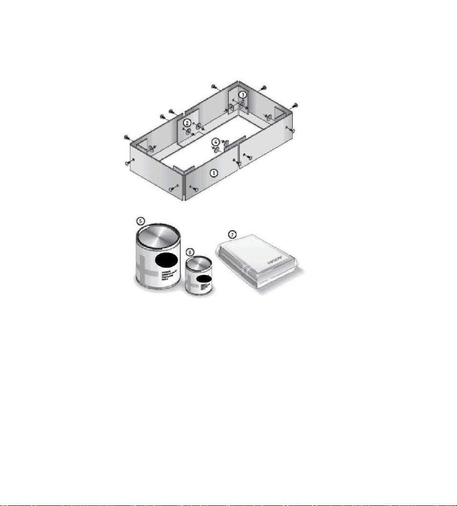
Figure 3.1 – Spill Control Barrier Components
1. B arr i er Stri p s
2. S p lice P l a tes
3. C o rner P l a te
4. Ass embly Hardw are
5. Acidsafe Coating (Part A) – floor coating version only
6. Acidsafe Coating (Part B) – floor coating version only
7. Acids afe Adh esive
Installation Manual Page 4 of 25
Page 6

Alpha Industrial Power Spill Control Barrier System
3. Initial Conditions
3.1 For maximum effectiveness of the Spill Control Barrier, the floor surface
should be flat, smooth and reasonably level. An uneven surface can
cause gaps between the Spill Control Barrier and the floor, which may
require additional Adhesive during final assembly. Unlevel or sloped floors
may require additional Coating to achieve minimum film thickness.
3.2 Permanent floor coverings such as vinyl, linoleum, composite or asbestos tiles
will not affect the ability of the Spill Control Barrier or Acidsafe Floor Coatings to
contain acid spills, provided that the coverings are in good condition and
securelyfastenedto the floor. Loose or broken tilesshould be removed and voids
filled using Joint/Crack Filler Kit (part number 5CFK0001).
CAUTION:
All asbestos handling precautions should be observed when handling loose
or broken asbestos tiles, including respiratory protection, protective clothing
and specialized disposal. Consult with the local authority having
jurisdiction for asbestos abatement requirements.
3.3 Concrete should be completely dry and properly cured (minimum of 28
days after poured). Concrete slabs installed on or below grade or otherwise
exposed to weather may transmit water vapor, causing pinholes in the floor
coating during cure. Evening (after 7 PM) is the most suitable time of day for a
ground-floor installation as the effects of concrete off-gassing will be
minimized.
3.4 Failure to properly clean and prepare the surface of the floor prior to applying
the Adhesive and Coating can cause adhesion failure or degraded chemical
resistance over time. Appropriate floor cleaning and other surface preparatory
procedures are described in Section 4.
3.5 Local amb ien t a ir temp era ture mu st be grea ter tha n 5 0˚F when ap plying
and curing the Adhesive and Coating materials. As ambient air
temperature decreases, the time necessary to set and cure the Acidsafe
Ad hesive and Co ating incr ease s. Cold co nditio ns (bel ow 50˚F) will also
impair the Coating’s application characteristics.
Installation Manual Page 5 of 25
Page 7

Alpha Industrial Power Spill Control Barrier System
3.6 The following tools and supplies are recommended for a quick and
thorough Barrier installation:
7/16 inch box end or combination wrench
putty knife
tape measure
several sheets of sandpaper, 100 grit
roll of 1 inch masking tape
goggles,chemicalresistantgloves andrespirator (asneeded)for
installers’ paper towels or shop rags
rubbing alcohol
3.6.1 Additional supplies needed for Spill Barrier with floor coating version
only:
small metal ruler with 1/64” increments or wet film thickness gauge.
The Coating Installation standard Tool Kit (part number
5BNK0001) contains: small rotary stirring tool, two v-notch trowels,
four v-notch spreaders, onemaskingtape, twobrushes,two gloves,
tworags, twoputty knives, one 3-piece extension, one 1-1/2 inch
spiked pin roller, one pair goggles, and two sheets sandpaper.
(Other kits available upon request)
4.FloorPreparation
4.1 The installer or site/equipment engineer must ensure that sufficient aisle space
will remain once the Barriers have been installed. There should be a minimum
of 30 inches between Barriers. Aisle spacing at the end of each rack may be as
little as 24 inches, providing no conflict exists with battery maintenance
requirements. The aisle spacing,includingthe space between the surrounding
Barriers, should be sufficienttopermitallrequired maintenance (includingbattery
installationandremoval). SeetheNationalElectric Codeorcontactthelocalauthority
having jurisdiction for further clarification regarding aisle clearances.
4.2 After clearances have been verified, locate and mark the outline of the
Barrierusing the Barrier’s dimensionsand a tape measure.TheBarriershould
becentered around the rack with at least 1 inch clearance in all directions
to meet 1995 Uniform Fire Code article 64 requirements.
Installation Manual Page 6 of 25
Page 8

Alpha Industrial Power Spill Control Barrier System
4.3 Completely clean and prepare the portion of flooring which will have Adhesive
or Coating applied during installation. For Barrier System versions without
floor coating, this area is a strip approximately 3 inches wide inside the
outline of the Barrier perimeter. For Barrier System versions with floor
coating, this includes the entire area inside the outline of the Barrier
perimeter. Prepare the flooring according to the following guidelines.
All Floor Types: Remove all oil, grease, dirt, efflorescence, laitance,
chemicals, hardeners,curing membranes,wax, previouslyapplied coatings or
othersurfacecontainments. Floors may be cleaned with an alkaline detergent
dissolvedin hot water, scrubbed with a non-metallic stripping pad and rinsed
several times. Alternatively, clean using steam, water (low pressure), air
blast, vacuum, and broom cleaning methods as described in ASTM D 4258
and SSPC-SP-1.
Concrete Floors: Roughen surface by abrading or etching. Concrete may
be etched with a 20% phosphoric acid solution, mechanically scrubbed, and
rinsed with a neutralizing solution (2 lb. Sodium bicarbonate and 1 gal.
Water) and followed by a clean water rinse. Alternatively, abrade by steel
shot blasting, sandblasting, water jetting with abrasive, power tool cleaning, or
scarifying as described in ASTM D 4258 and NACE RP-01-72.
4.4 Perform a check for cleanliness by rubbing the floor with a clean, white cloth.
If the cloth appears dirty, perform Step 4.3 again. Also check surface
preparation by performing the following ‘water-break’ test: pour a small
amount of clean water onto the surface and observe. If water evenly wets
the surface, the cleaning is adequate.If the water forms beads on the
surface,performStep 4.3 again. Allow surfaces to completely dry before
applying Adhesive or Coating.
4.5 Use 100 grit aluminum oxide or silicon carbide sandpaper to lightly sand the
underside of the Barrier Strips and the mating surfaces of the connector
plates. Wipe all sanding debris from the Barrier Strips with a clean rag.
4.6 Inspect the floor inside the containment area for any progressive cracks
greater than 1/8 inch in width, as well as for control/expansion joints. Such
surface defects must be repaired or filled with a Joint/Crack Filler before
progressing any further with the Spill Control System installation. Smaller
defects may be filled using Adhesive and a putty knife. A Joint/Crack Filler
Kit is available from Alpha Industrial Power.
Installation Manual Page 7 of 25
Page 9

Alpha Industrial Power Spill Control Barrier System
Figure 5.1 – Mixing the Adhesive
Figure 5.2 – Preparing Mixing Bag for Application
5. Barrier Installation
5.1 Lay out the Barrier Strips on the floor around the battery stand location in the
order demonstrated in Figure 3.1 and lightly bolt the pieces together using
carriage bolts, washers, nuts and the appropriate connector plates. Position
the barrier around the batterystand location to provide equal clearances on all
sides between the battery stand and the barrier. Note that the horizontal
flange on all of the barrier strips faces the battery stand (Figure 3.1). This
orientation is important both for barrier clearance and liquid-tight integrity.
CAUTION:
Barrier strips and connectorsareconstructed fromsteelandcoatedwith an acid
resistant epoxy. These strips should be handled with care near all electric
power sources. Contact with an electrical source could result in severe shock
or death. This product should only be installed by trained professionals
familiar with the electrical hazards of high energy DC back up power systems.
Installation Manual Page 8 of 25
Page 10

Alpha Industrial Power Spill Control Barrier System
5.2 After assembling and positioning the barrier system, mark the outer
perimeter of the barrier on the floor using 1 inch masking tape. This will
mark the proper placement of the Barrier and will help keep the floor clean
from adhesive overage or coating splatters and drips.
5.3 Check for uneven flooring by measuring the gap between the bottom of the
barrier and the floor. Gaps greater than 1/8 inch should be marked for the
application of additional Adhesive material during the barrier assembly
process. After marking large gaps, disassemble the parts for application of
Adhesiveand final assembly.
5.4 Prepare Adhesive by removing the separator between Part A and Part B
in the two part pouch. Knead the package vigorously and work the material
from end to end until the epoxy appears thoroughly mixed. To ensure complete
and thorough mixing,continue kneading for severalminutes after the Adhesive
material has achieved an even consistency and color. Poorly mixed Adhesive
will not fully cure, resultingin a failure to bond the Barrier securely to the floor
and to poor chemical resistance.
CAUTION:
The Adhesive and Coating materials are immediate eye irritants and, after
prolonged exposure, skin and lung irritants. Wear safety goggles, long
sleeved shirt, chemical resistant gloves and a NIOSH/MSHA TC-23C
approved respirator (respirator requiredfor inadequate ventilation situations
only) when mixing and applying these compounds. See the MSDS for
additional safety and handling instructions.
NOTE:
Once prepared, the Adhesive and Coating materials should be applied without
delay. Interaction between Part A and Part B of the Adhesive generates heat
that will acceleratethehardening process.Always grasp pouch by the rolled end
to avoid discomfort due to heat generation.
5.5 Roll the end of the bag such that the empty space has been taken up
(Figure 5.1). Diagonally cut one of the bottom corners so that the bag may
be used as an applicator (Figure 5.2). Squeezing the bag will apply a bead
of Adhesive.
5.6 Use the Adhesive to fill any defects in the floor inside the containment area that
havenotbeen previously filledusing the Joint/CrackFiller Kit. Use a puttyknife
to scrape the filled areas flush with the surrounding surface.
Installation Manual Page 9 of 25
Page 11

Alpha Industrial Power Spill Control Barrier System
5.7 In facilities where a battery rack is already installed, use a spreader or putty
knife to sealthebase of the batteryrackwithAdhesive as shown in Figure 5.3.
Usinga brush, apply Adhesive to the battery rack anchoring hardware as shown
in Figure 5.4.
5.8 Starting at one corner, apply a thick bead of Adhesive to the bottom
surface of two of the Barrier Strips and spread evenly over the flange with a
3/16 inch v-notch trowel. Use the 1/4 inch v-notch trowel if additional adhesive
is required for filling gaps. Press the strips into place on the floor and align
them to the markings made in Step 4.3.
5.9 Apply Adhesive to the mating surfaces of the Corner Plate, spread the
Adhesive evenly over the surface using a 1/8 inch v-notch trowel, and press
the plate into place over the joint (Figure 5.5). Lightly bolt the Corner Plate to
the Strips using a carriage bolt, flat washer and hex bolt arrangement.
5.10 Proceed along the Barrier perimeter while repeating steps 5.6 and 5.7.
Use a Splice Plate where joining Strips is required (Figure 5.6).
Figure 5.3 – Sealing Rack Frames
Installation Manual Page 10 of 25
Page 12

Alpha Industrial Power Spill Control Barrier System
Figure 5.4 – Coating Rack Hardware
5.11 At each corner joint, apply a bead of Adhesive over the mitered seam
and spread the material flush with a putty knife.
5.12 Recheck the alignment and position of the barrier and its components
and tighten all of the assembly hardware using a 7/16 inch box-end or
combination wrench. The hardware has been properly tightened when
Adhesive material starts to squeeze out evenly around the edges of the
connector plates. Avoid over tightening as this will cause an Adhesivestarved joint. Use a putty knife to scrape away the excess adhesive and
use it to fill any voids under the Barrier Strips.
5.13 Clean any Adhesive that hasbeenspilledusing a cloth lightlydampened
withdenatured or rubbing alcohol.
5.14 Retain any mixed Adhesive that is left over for leak repair during the
coating process. If leak repair is not necessary, allow the Adhesive to
harden in its container and dispose of in accordance with local, state and
federal regulations.
5.15 If installing a Barrier System without floor coating, remove masking and
proceed to Section 7 for information on performing a leak test of the Barrier.
Installation Manual Page 11 of 25
Page 13

Alpha Industrial Power Spill Control Barrier System
Figu
re 5.5–Assembling Barrier
Figure 5.6 – Assembling Barrier Splices
Installation Manual Page 12 of 25
Page 14

Alpha Industrial Power Spill Control Barrier System
6. Coating Application (Barrier System with floor coating version only)
6.1 Verify that the proper quantities of Acidsafe Floor Coating Part A and Part B
are matched up properly in preparation for mixing. A 1 gallon kit will be
comprised of one 1 gallon can of Part A and a 1 quart can of Part B.
6.2 Pour all of Part B into a corresponding container of Part A and blend with a
rotary stirrer and an electricdrillon moderate speed (approximately700 rpm).
Keep the stirring vanes well below the surface of the Coating to avoid
entraining air bubbles into the mixture. Continue to stir the Coating
compound for several minutes after the mixture has achieved an even color
and pay special attention to unmixed material at the sides and bottom of the
container. Mix additional Coating as necessary during the coating process to
complete the installation. Improperly mixedCoating willnotcompletelycure,
resulting in reduced chemicalresistance and poor performance.
6.3 Pour and spread the Coating evenly over the floor inside the containment
area using a plastic spreader or putty knife (Figure 6.2). If installing the coating
under an existing rack, try to allocate equal amounts of coating material
betweeneachset of rackframes.Spread thecoatingusinga 1/4inch v-notch
spreader to obtain a uniform thickness. Figure 6.1 shows coating being
applied under a rack. Note thatthebatteries are not illustratedforreasons of
clarity;batteries DO NOT need to be removed in order to apply the coating.
Figure 6.1 – Spreading Acidsafe Around Existing Racks
Installation Manual Page 13 of 25
Page 15

Alpha Industrial Power Spill Control Barrier System
Figure 6.2 – Spreading Acidsafe in New Installations
6.4 Check that Coating thickness in all areas is at least 5/64 inches using a
small metal ruler or 80 mils on a film gauge. Spread the Coating as
necessary to achieve a uniform thickness. If the film thickness in an area
is insufficient, pour additional Coating or use the spreader to redistribute
the Coating as necessary.
6.5 Use a spiked pin roller (available in the Coating Installation Tool Kit) to
rupture any air bubbles. If no spiked pin roller is available or in places that
the spiked pin roller is unable to reach, break the surface of any bubbles
seen by probing them with an unfolded paper clip.
6.6 Inspect the perimeter of the barrier for seepage. If Coating is seeping under
the barrier, use a spreader or gloved finger to force some remaining Adhesive
under the Barrierin the area of the leak until the flow stops. If no usable
Adhesive remains,a piece of Coating-saturatedpaper towel may also be used.
6.7 Remove the masking tape from the floor around the barrier.
Installation Manual Page 14 of 25
Page 16

Alpha Industrial Power Spill Control Barrier System
6.8 Any mixed Coating that has been spilled may be absorbed with cat litter box
filler and wiped up with a cloth moistened with denatured or rubbing alcohol.
Allow remaining Coating material to harden in its container and dispose of
in accordance with local, state and federal regulations.
6.9 In installations where Coating is installed before the battery system, racks may
be positioned only after the Coating has been completely cured. If a leak test
is to be performed, it also must be satisfactorily completed prior to rack
installation. Do not load the racks with batteries until the Coating has had at
least one week to completely cure. Once the battery racks have been
installed, obtain a Leak Repair Kit (part number 5LRK0001) and use it to seal
the frames (Figure 5.3) and anchors (Figure 5.4).
7. Leak Test
7.1 The barrier leak test is an optional procedure to verify the liquid-tight integrity
of the Spill Control System. After the Coating and the Adhesive have been
permitted to cure for 24 hours, perform a leak test by filling the Barrier system
with water and allowing it to stand while checking for leaks. If any leakage
occurs, identify and mark the unsealed location.
7.2 Drain the barrier and make sure the floor is clean and dry. In most cases, a
wet/dryshop vacuum is the quickest and easiest method to remove the water
from the barrier.
7.3 If leakage is found, obtain a Leak Repair Kit from Alpha Industrial Power.
Follow the enclosed instructions to mix an appropriate quantity of Adhesive
and brush it over the area of the leak until the crack or seam is no longer
evident. Allow the repair 24 hours to cure before retesting.
Installation Manual Page 15 of 25
Page 17

Alpha Industrial Power Spill Control Barrier System
8. Coating Maintenance
8.1 Coating integrity is important to the effectiveness of the Barrier system. The
elastic nature of the Coating typically resists cracking and chipping in a
conventional battery room environmentandnoreapplicationsarelikelytobe
required for the lifetime of the batterysystem.However,extremeconditionsor
circumstancesmaydamage the surface of the Coating. For that reason, it must
undergo periodic inspection and occasional repair.
8.2 If the battery facility has experienced an earthquake or other event in which
damage to the floor has occurred in the area of the Barrier, remove the
Neutra-Mats and perform an inspection of the floor inside the barrier to
detect any cracks or breaks in the Coating. Fill a one quart atomizing bottle
with at least 16 ounces of distilled water, 1 to 2 fluid ounces of food dye and 6
to 8 drops of a surfactant such as Dawn or Ivory liquid dish soap. Shake well
and mist the suspect area. Wipe the sprayed area with a damp rag and any
fractures will appear as dye-colored lines. If cracks or defects are found,
repair as follows:
8.3 Obtain a Leak Repair Kit (part number 5LRK0001) from Alpha Industrial
Power. Ensure that the area is completely dry. Sand an area at least 1 inch
on all sides of the crack or chip for the entire length of the defect using 100
grit aluminum oxide or silicon carbide sandpaper. Remove any sanding
debris.
8.4 Mix the Adhesive in the Leak Repair Kit and brush the repair material over
the sanded area untilthecrackis no longer evident.Allow the repair 24 hours to
cure before placing anything on top of it, such as Neutra-Mats.
8.5 For cracks larger than 1/8 inch in width, ensure that no structural damage
has occurred that will endanger the battery facility. Obtain a Joint/Crack
Filler Kit from Alpha Industrial Power and repair the crack in accordance
with the enclosed instructions.
Installation Manual Page 16 of 25
Page 18

Alpha Industrial Power Spill Control Barrier System
Revision Date: March 18, 2008 MSDS No. AAG (A)
MATERIAL SAFETY DATA SHEET
Product Name:
ChemicalFamily: EpoxyResinMixture
CompanyName: EasternResinsCorp.
ADHESIVEGEL(RESIN),PART-A
1174River Street Woonsocket,RI
02895,USA
BUSINESS PHONE:
EMERGENCYPHONE:
(401)769-6700
(800)255-3924
2. COMPOSITION
1. MATERIAL IDENTIFICATION
ExposureLimits
ChemicalName Wt % TLV-TWA PEL
EpoxyresinMixture >70 N/E N/E
TitaniumDioxide * <10 10 mg/m3 15 mg/m3
Carbonblack* <1 3.5 mg/m3 3.5 mg/m3
Fumedsilica* <10 20 mppcf 20mppcf
Specific ingredients are considered aTradeSecret
Abbreviations:N/E -NOT ESTABLISHED
* - Materialsarein
Non-Airborne
form
ACGIH OSHA
3. HEALTH HAZARDS
PrimaryRoutesofExposure:
EyeContact
SkinContact
and temporary orpermanent sensitization.
Ingestion:
Other
: May causeirritation and swelling.
:Maycause irritationandsensitization. Symptomscanbe immediate or delayedseveralhours.
Maycause irritation.
: Preexisting skin sensitization may be aggravated by exposureto thisproduct.
Eyes: Yes Skin: Yes Inhalation: Yes
Inhalation:
May cause irritation
4. FIRST AID MEASURES
Eyes:
Flusheyes thoroughly with waterfor atleast 15minutes while holdingeyelidsopen. Seekmedicalattention.
Skin:
Remove contaminatedclothing. Wipe excess from skin and wash the affectedareathoroughlywithsoap and water.Wash contaminated clothing thoroughly
beforereuse.
Inhalation:
Ingestion:
Remove tofreshair,andprovideoxygenor artificialrespiration if needed.Obtainmedicalattention;symptoms can be delayed upto several hours.
DO NOT inducevomiting. Give 1-2 cups of water or milk unlessthe personis drowsy,convulsing, or unconscious.Get medical attention.
5. FIREFIGHTING MEASURES
FlammableProperties:Flash Point
ExplosiveLimits:
HazardousDecompositionProducts
EXTINGUISHING MEDIA AND FIRE FIGHTING INSTRUCTIONS
full bunker gear, including a positive pressure, NIOSH approved, self-contained breathing apparatus. Extreme heat or water contamination may cause closed
containersto explode.
ExtinguishingMedia
: Use carbondioxide, dry chemicalor appropriate foam
: >300oF(PMCC)
: Carbonmonoxide, carbon dioxide, aldehydes, andother organic substances.
Notapplicable
Auto-IgnitionTemperature:
: When sufficiently large quantities are present, firefighters should be equipped with
Notapplicable
6. ACCIDENTAL RELEASE MEASURES
Ventilatethe spill area andevacuate if necessary. Removeall ignition sources. Dike and contain large spills. Clean-up personnel should use adequateprotective
equipment.
Storein acool;dry place, in closed containersat room temperature. Avoid contactwith incompatiblematerials. Wear protectiveeyewear,chemical-resistant gloves, and
otherprotective clothing asappropriate.
Installation Manual Page 17 of 25
7. HANDLING ANDSTORAGE
Page 19

Alpha Industrial Power Spill Control Barrier System
8.EXPOSURE CONTROLAND PERSONALPROTECTION
Engineering/Ventilation Controls:
worker exposure to all respiratory hazards. General ventilation, local ventilation, or isolation may prove adequate to keep airborne
concentrationsbelowexposurelimits.
RespiratoryProtection
SkinProtection
EyeProtection
: Not requiredunder normal conditions in a well-ventilatedworkplace.
: Imperviousglovesand protectiveclothingshouldbe worn asnecessary.
: Chemical splash goggles orsafety glasses withside shields should beworn asappropriate.
Effective engineering controls should be used whenever possible to eliminate and/or reduce
9. STABILITY ANDREACTIVITY
Chemical Stability
ConditionsandMaterialstoAvoid:
agents.
HazardousPolymerization
: Stable undernormal conditions anduse.
Reactswithaminesandstrongoxidizing
: Will not occur.
10.PHYSICALANDCHEMICALPROPERTIES
Appearance/Odor:
VaporPressure(mmHg
SpecificGravity:
): <1@25oC
GrayPaste,slightether odor
1.2-1.3
BoilingPoint
Vapor Density(air=1) :
SolubilityinWater:
: Not determined
None
11.TOXICOLOGICALINFORMATION
This section provides toxicological information with regard to the pure form of the componentindicated. It is suggested that
personstrained in its evaluation interpretthis information.
EpoxyResins: AcuteOral
AcuteDermal
(Rat): 11.4 g/kg
LD
50
(Rabbit): >20 g/kg
LD
50
12.DISPOSALCONSIDERATIONS
Keep out of surface waters, sewers, and waterways entering or leading to surface waters. Notify authorities if any exposure to the
environment occurs or is likely to occur. Utilize an appropriate disposal facility, in compliance with applicable federal, state, and
localenvironmental control regulations.
13.TRANSPORTATIONINFORMATION
DOT/IATAProperShippingName
TSCA:
Thechemicalcomponentsof this productareincludedinthe TSCA ChemicalSubstance Inventory,as required.
SARA TITLEIII:
Section313– ToxicChemicals
Section 311/312– HazardCategories
FireHazard:
SuddenReleaseofPressureHazard:
Delayed(Chronic)HealthHazard
OSHAHazardCommunicationStandardHazardClasses
NFPAHazards:
HMISHazards:
Health: 2 Flammability:1 Reactivity: 0
Health: 2 Flammability:1 Reactivity: 0
: Not Regulated
14. REGULATORYINFORMATION
: None
:
: No
No
No
:
ReactivityHazard:
Immediate(Acute)HealthHazard
: Yes
>1
No
This information is furnished without warranty, expressed or implied, except that it is accurate to the best of our knowledge. The
data on this sheet relates only to the specific material designated herein.
for use or reliance uponthese data.
Eastern Resins Corp.assumes no legal responsibility
Installation Manual Page 18 of 25
Page 20

Alpha Industrial Power Spill Control Barrier System
ExposureLimits
ACGIH
OSHA
Cycloaliphaticamine
50-70
N/E
N/E
Revision Date: March 18, 2008 MSDSNo. AAG (B)
MATERIAL SAFETY DATA SHEET
ProductName:
ChemicalFamily: AMINEMIXTURE
CompanyName:
ChemicalName Wt % TLV-TWA PEL
Aliphaticamine 30-50 N/E N/E
Specificingredientsareconsidereda TradeSecret
ADHESIVEGEL(HARDENER),PART-B
Eastern ResinsCorp.
1174RiverStreet
Woonsocket,RI02895,USA
1. MATERIAL IDENTIFICATION
BUSINESSPHONE:
EMERGENCYPHONE:
2. COMPOSITION
(401)769-6700
(800)255-3924
Abbreviations:N/E- NOTESTABLISHED
*-Materialsarein
Non-Airborne
form
3. HEALTH HAZARDS
PrimaryRoutesofExposure: Eyes
EyeContact
SkinContact:
Inhalation
Ingestion:
Other:
:Causesevereirritationandmaycauseburn.
Causeirritationandsensitization.Symptomscanbeimmediateordelayedseveralhours.
: Can causerespiratorytractirritation.
Cancause nausea,headache,andgastrointestinal irritation.
Preexistingskin sensitizationmaybeaggravated by exposuretothisproduct.
: Yes
Skin:
Yes
Inhalation:
Yes
4. FIRST AID MEASURES
Eyes:
Flush eyesthoroughly withwaterforat least15minuteswhile holdingeyelidsopen.Seekmedicalattention.
Skin:
Removecontaminatedclothing.Wipeexcessfromskinandwashtheaffectedareathoroughlywithsoapandwater.Wash
contaminatedclothing thoroughlybeforereuse.
Inhalation:
delayedup to severalhours.
Ingestion
medicalattention.
Removetofreshair,andprovideoxygenorartificialrespirationifneeded.Obtainmedicalattention;symptomscanbe
:DONOTinducevomiting.Give1-2cupsofwaterormilkunlessthepersonisdrowsy,convulsing,orunconscious.Get
5. FIRE FIGHTING MEASURES
FlammableProperties:FlashPoint
ExplosiveLimits:
HazardousDecompositionProducts
EXTINGUISHING MEDIA AND FIRE FIGHTING INSTRUCTIONS
firefighters should be equipped with full bunker gear, including a positive pressure, NIOSH approved, self-contained breathing
apparatus.Extremeheatorwater contaminationmaycause closedcontainersto explode.
ExtinguishingMedia
:Usecarbondioxide, drychemicalor appropriatefoam.
: >200oF(PMCC)
Notapplicable
: oxidesofnitrogen, Carbon monoxide,carbon dioxideandotherorganicmaterials.
Auto-IgnitionTemperature:
: When sufficiently large quantities are present,
Notapplicable
6. ACCIDENTAL RELEASE MEASURES
Ventilatethespillareaandevacuateifnecessary.Removeallignitionsources.Dikeandcontainlargespills.Flushareawithwater
spray.Clean-uppersonnelshoulduseadequateprotectiveequipment.
Installation Manual Page 18 of 25
Page 21

Alpha Industrial Power Spill Control Barrier System
Revision Date: March 18, 2008 MSDS No. AAG (B)
7. HANDLING AND STORAGE
Storeina cool;dryplace,inclosedcontainersat roomtemperature.Avoidcontactwithincompatiblematerials.Wearprotective
eyewear,chemical-resistantgloves,and otherprotectiveclothingas appropriate.
8. EXPOSURE CONTROLANDPERSONAL PROTECTION
Engineering/Ventilation Controls:
worker exposure to all respiratory hazards. General ventilation, local ventilation, or isolation may prove adequate to keep airborne
concentrations belowexposurelimits.
RespiratoryProtection
SkinProtection
EyeProtection
:Notrequiredunder normalconditionsin awell-ventilatedworkplace.
:Imperviousglovesandprotectiveclothingshouldbe wornasnecessary.
:Chemicalsplashgogglesor safetyglasses withsideshieldsshouldbe wornasappropriate.
Effective engineering controls should be used whenever possible to eliminate and/or reduce
9. STABILITY AND REACTIVITY
ChemicalStability
ConditionsandMaterialstoAvoid:
Hazardous Polymerization:
: Stableundernormalconditionsanduse.
Reactswithepoxyandstrongoxidizingagents.
Will notoccur.
10.PHYSICALAND CHEMICALPROPERTIES
Appearance/Odor:
VaporPressure(mmHg
SpecificGravity:
Amberliquid,ammoniacalodor
): <1@25oC
1.04
BoilingPoint
Vapor Density(air=1):
SolubilityinWater:
: Notdetermined
>1
Slightly soluble
11.TOXICOLOGICAL INFORMATION
AcuteToxicityData:
Notavailable
ChronicToxicityData:
Notavailable
12.DISPOSALCONSIDERATIONS
Keep out of surface waters, sewers, and waterways entering orleadingto surface waters. Notify authorities ifany exposure tothe
environmentoccurs or is likelyto occur.Utilizean appropriate disposal facility,in compliancewithapplicable federal, state, and
localenvironmentalcontrolregulations.
DOT/IATAProperShippingName
13.TRANSPORTATION INFORMATION
:NotRegulated
14.REGULATORYINFORMATION
TSCA:
ThechemicalcomponentsofthisproductareincludedintheTSCAChemicalSubstanceInventory,asrequired.
SARATITLEIII:
Section313–ToxicChemicals
Section311/312– HazardCategories
FireHazard:
SuddenReleaseofPressureHazard:
Delayed(Chronic)HealthHazard
OSHAHazardCommunicationStandardHazardClasses
NFPAHazards:
HMISHazards:
Health:3 Flammability:1 Reactivity:0
Health:3 Flammability:1 Reactivity:0
: None
:
No
No
: No
ReactivityHazard:
Immediate(Acute)HealthHazard
:
No
: Yes
Thisinformationis furnished without warranty,expressedor implied,exceptthat it isaccurate to the bestof our knowledge. The
data on this sheet relates only to the specific material designated herein.
responsibilityforuseorrelianceupon thesedata.
Eastern Resins Corp.assumes no legal
Page 22

Alpha Industrial Power Spill Control Barrier System
ExposureLimits
TLV-TWA
PEL
Revision Date: March 18, 2008 MSDS No. ANFC (A)
MATERIALSAFETYDATASHEET
ProductName:
ChemicalFamily: EpoxyResinMixture
CompanyName:
ChemicalName Wt %
Epoxy resin Mixture
Titanium Dioxide *
Carbon black*
Specificingredients areconsidereda TradeSecret
Abbreviations:N/E- NOTESTABLISHED
PrimaryRoutesofExposure:
Eye Contact
SkinContact
Inhalation:
Ingestion:
Other
Eyes:
Skin:
contaminatedclothing thoroughlybeforereuse.
Inhalation:
delayedup to severalhours.
Ingestion:
medicalattention.
FlammableProperties:FlashPoint
ExplosiveLimits:
HazardousDecompositionProducts
EXTINGUISHING MEDIA AND FIRE FIGHTING INSTRUCTIONS
firefighters should be equipped with full bunker gear, including a positive pressure, NIOSH approved, self-contained breathing
apparatus.Extremeheatorwater contaminationmaycause closedcontainersto explode.
Extinguishing Media
Ventilatethespillareaandevacuateifnecessary.Removeallignitionsources.Dikeandcontainlargespills.Clean-uppersonnel
should useadequateprotectiveequipment.
:Maycauseirritationand swelling.
:Maycauseirritationandsensitization.Symptomscanbeimmediateordelayedseveralhours.
Maycauseirritation and temporaryorpermanentsensitization.
Maycauseirritation.
:Preexisting skinsensitization may be aggravatedby exposureto thisproduct.
Flusheyesthoroughlywithwater forat least15minuteswhileholding eyelids open.Seekmedical attention.
Removecontaminatedclothing.Wipeexcessfromskinandwashtheaffectedareathoroughlywithsoapandwater.Wash
Removetofreshair,andprovideoxygenorartificialrespirationifneeded.Obtainmedicalattention;symptomscanbe
DONOTinducevomiting.Give1-2cupsofwaterormilkunlessthepersonisdrowsy,convulsing,orunconscious.Get
NOVOLACFLOORCOATING(RESIN),PART-A
Eastern ResinsCorp.
1174 River Street
Woonsocket,RI02895,USA
*- Materialsarein
:Usecarbon dioxide,drychemical or appropriate foam
1. MATERIAL IDENTIFICATION
BUSINESSPHONE:
EMERGENCYPHONE:
(401) 769-6700
(800) 255-3924
2. COMPOSITION
Non-Airborne
form
>70
<10
<1
ACGIH
N/E
10 mg/m3
3.5mg/m3
OSHA
N/E
15mg/m3
3.5mg/m3
3. HEALTH HAZARDS
Eyes: Yes Skin: Yes Inhalation: Yes
4. FIRST AID MEASURES
5. FIRE FIGHTING MEASURES
: >300oF(PMCC)
Notapplicable
: Carbon monoxide,carbondioxide,aldehydes,andotherorganicsubstances.
Auto-IgnitionTemperature:
: When sufficiently large quantities are present,
Notapplicable
6. ACCIDENTAL RELEASE MEASURES
Installation Manual Page 20 of 25
Page 23

Alpha Industrial Power Spill Control Barrier System
Storeina cool;dryplace,inclosedcontainersat roomtemperature.Avoidcontactwithincompatiblematerials.Wearprotective
eyewear,chemical-resistantgloves,and otherprotectiveclothingas appropriate.
7. HANDLING AND STORAGE
8. EXPOSURE CONTROLANDPERSONAL PROTECTION
Engineering/Ventilation Controls:
worker exposure to all respiratory hazards. General ventilation, local ventilation, or isolation may prove adequate to keep airborne
concentrations belowexposurelimits.
RespiratoryProtection
containedbreathingapparatusisrequired.
SkinProtection
EyeProtection
:Ifexposurelimitsareexceededandlocalventilationisunavailable,a supplied-airrespiratorora self-
:Imperviousglovesandprotectiveclothingshouldbe wornasnecessary.
:Chemicalsplashgogglesor safetyglasses withsideshieldsshouldbe wornasappropriate.
Effective engineering controls should be used whenever possible to eliminate and/or reduce
9. STABILITY AND REACTIVITY
ChemicalStability
ConditionsandMaterialstoAvoid:
HazardousPolymerization
: Stableundernormalconditionsanduse.
Reactswithaminesandstrongoxidizingagents.
:Willnotoccur.
10.PHYSICALAND CHEMICALPROPERTIES
Appearance/Odor:
VaporPressure(mmHg
SpecificGravity:
): <1@25oC
Grayliquid,slightetherodor
1.2
BoilingPoint
Vapor Density(air=1):
: Notdetermined
SolubilityinWater:
>1
None
11.TOXICOLOGICAL INFORMATION
Thissectionprovidestoxicologicalinformationwith regardtothepureformofthecomponentindicated.Itissuggestedthat
personstrainedin itsevaluation interpretthisinformation.
EpoxyResins: AcuteOral
AcuteDermal
(Rat): 11.4g/kg
LD50
(Rabbit): >20 g/kg
LD50
12.DISPOSALCONSIDERATIONS
Keep out of surface waters,sewers, and waterways entering or leadingto surface waters. Notify authorities ifany exposure to the
environmentoccurs or is likelyto occur.Utilizean appropriate disposal facility,in compliancewithapplicable federal, state, and
localenvironmentalcontrolregulations.
13.TRANSPORTATION INFORMATION
DOT/IATAProperShippingName
TSCA:
ThechemicalcomponentsofthisproductareincludedintheTSCAChemicalSubstanceInventory,asrequired.
SARATITLEIII:
Section313–ToxicChemicals
Section311/312– Hazard Categories
FireHazard:
SuddenReleaseofPressureHazard:
Delayed(Chronic)HealthHazard
OSHAHazard CommunicationStandardHazardClasses
NFPAHazards:
HMISHazards:
Health:2 Flammability:0 Reactivity:0
Health:2 Flammability:0 Reactivity:0
:NotRegulated
14.REGULATORYINFORMATION
: None
:
No
No
: No
ReactivityHazard:
Immediate(Acute)HealthHazard
:
No
: Yes
Thisinformationis furnishedwithoutwarranty, expressedorimplied,exceptthatit is accurateto the bestofour knowledge.
Thedata on this sheet relates only to the specific material designated herein.
legal responsibility for use or reliance upon these data.
Eastern ResinsCorp.assumes no
Installation Manual Page 21 of 25
Page 24

Alpha Industrial Power Spill Control Barrier System
Revision Date: March 18, 2008
MSDSNo.ANFC(B)
MATERIAL SAFETY DATA SHEET
ProductName:
ChemicalFamily: AMINE MIXTURE
CompanyName:
ChemicalName Wt% TLV-TWA PEL
Cycloaliphaticamine 50-70 N/E N/E
Aliphaticamine 30-50 N/E N/E
Specific ingredientsareconsidereda TradeSecret
Abbreviations:N/E- NOTESTABLISHED
PrimaryRoutesofExposure: Eyes
EyeContact
SkinContact:
Inhalation
Ingestion:
Other:
Eyes:
Skin:
contaminatedclothing thoroughlybeforereuse.
Inhalation:
delayedup to severalhours.
Ingestion
medicalattention.
FlammableProperties:FlashPoint
ExplosiveLimits:
HazardousDecompositionProducts
EXTINGUISHING MEDIA AND FIRE FIGHTING INSTRUCTIONS
firefighters should be equipped with full bunker gear, including a positive pressure, NIOSH approved, self-contained breathing
apparatus.Extremeheatorwater contaminationmaycause closedcontainersto explode.
ExtinguishingMedia
Ventilatethespillareaandevacuateifnecessary.Removeallignitionsources.Dikeandcontainlargespills.Flushareawithwater
spray.Clean-uppersonnelshoulduseadequateprotectiveequipment.
:Causesevereirritationandmaycauseburn.
Causeirritation andsensitization.Symptomscanbeimmediateordelayed severalhours.
: Can causerespiratorytractirritation.
Cancause nausea,headache,andgastrointestinal irritation.
Preexistingskin sensitizationmaybeaggravated by exposuretothisproduct.
Flush eyesthoroughly withwaterforat least15minuteswhile holdingeyelidsopen.Seekmedicalattention.
Removecontaminatedclothing.Wipe excessfromskinandwashtheaffectedareathoroughlywithsoapandwater.Wash
Removetofreshair,andprovide oxygenorartificialrespirationifneeded.Obtainmedicalattention;symptomscanbe
:DONOTinducevomiting.Give1-2cupsofwaterormilkunlessthepersonisdrowsy,convulsing,orunconscious.Get
NOVOLACFLOORCOATING(HARDENER),PART-B
Eastern ResinsCorp.
1174RiverStreet BUSINESSPHONE: (401) 769-6700
Woonsocket,RI02895, USA EMERGENCYPHONE:(800)255-3924
*- Materialsarein
:Usecarbondioxide, drychemicalor appropriatefoam.
1. MATERIAL IDENTIFICATION
2. COMPOSITION
ExposureLimits
ACGIH OSHA
Non-Airborne
form
3. HEALTH HAZARDS
: Yes
Skin:
Yes
Inhalation:
Yes
4. FIRST AID MEASURES
5. FIRE FIGHTING MEASURES
: >200oF(PMCC)
Notapplicable
: oxidesofnitrogen,Carbonmonoxide,carbon dioxideandotherorganicmaterials.
Auto-IgnitionTemperature:
: When sufficiently large quantities are present,
Notapplicable
6. ACCIDENTAL RELEASE MEASURES
Installation Manual Page 22 of 25
Page 25

Alpha Industrial Power Spill Control Barrier System
7. HANDLING AND STORAGE
Storeina cool;dryplace,inclosedcontainersat roomtemperature.Avoidcontactwithincompatiblematerials.Wearprotective
eyewear,chemical-resistantgloves,and otherprotectiveclothingas appropriate.
8. EXPOSURE CONTROL ANDPERSONAL PROTECTION
Engineering/Ventilation Controls:
worker exposure to all respiratory hazards. General ventilation, local ventilation, or isolation may prove adequate to keep airborne
concentrations belowexposurelimits.
RespiratoryProtection
containedbreathingapparatusisrequired.
SkinProtection
EyeProtection
ChemicalStability
ConditionsandMaterialstoAvoid:
Hazardous Polymerization:
:Ifexposurelimitsareexceededandlocalventilationisunavailable,a supplied-airrespiratorora self-
:Imperviousglovesandprotectiveclothingshouldbe worn as necessary.
:Chemicalsplashgogglesor safetyglasses withsideshieldsshouldbe wornasappropriate.
: Stableundernormalconditionsanduse.
Effective engineering controls should be used whenever possible to eliminate and/or reduce
9. STABILITY AND REACTIVITY
Reactswithepoxyandstrongoxidizingagents.
Will notoccur.
10.PHYSICAL AND CHEMICALPROPERTIES
Appearance/Odor:
VaporPressure(mmHg
SpecificGravity:
): <1@25oC
Amberliquid,ammoniacalodor
1.0
BoilingPoint
Vapor Density(air=1):
: Notdetermined
SolubilityinWater:
>1
Slightly soluble
11.TOXICOLOGICAL INFORMATION
AcuteToxicityData:
Notavailable
ChronicToxicityData:
Notavailable
12.DISPOSAL CONSIDERATIONS
Keep out of surface waters,sewers, and waterways entering or leadingto surface waters. Notify authorities ifany exposure to the
environmentoccurs or is likelyto occur.Utilizean appropriate disposal facility,in compliancewithapplicable federal, state, and
localenvironmentalcontrolregulations.
13.TRANSPORTATIONINFORMATION
DOT/IATAProperShippingName
:NotRegulated
14.REGULATORYINFORMATION
TSCA:
ThechemicalcomponentsofthisproductareincludedintheTSCAChemicalSubstanceInventory,asrequired.
SARATITLEIII:
Section313–ToxicChemicals
Section311/312– Hazard Categories
FireHazard:
SuddenReleaseofPressureHazard:
Delayed(Chronic)HealthHazard
OSHA HazardCommunicationStandardHazardClasses
NFPAHazards:
HMISHazards:
Health:3 Flammability:1 Reactivity:0
Health:3 Flammability:1 Reactivity:0
: None
:
No
No
: No
ReactivityHazard:
Immediate(Acute)HealthHazard
:Corrosive
No
: Yes
Thisinformationis furnishedwithoutwarranty, expressedorimplied,exceptthatit is accurateto the bestofour knowledge.
Thedata on this sheet relates only to the specific material designated herein.
legal responsibility for use or reliance upon these data.
Eastern ResinsCorp.assumes no
Installation Manual Page 23 of 25
Page 26

Alpha Industrial Power Spill Control Barrier System
Neutra
-
Tube
MATERIALSAFETY DATASHEET
SectionI GeneralInformation
Manufacturer:
AcranSpill Containment, Inc.
105-D Snyder Road
South Plainfield,NJ 07080
DatePrepared: Telephone Number for Information:
8September2008 (908) 769-6915
SectionII Hazardous Ingredients and Identity Information
Neutralizer/Absorber Blend CAS #: Trade Secret Weight>99% NuisanceDust
OSHAPEL: 15mg/M3Totaldust,5 mg/M3Respirabledust ACGIHTLV:
10mg/M3Total dust
ColorChangeAgent CAS #: Trade Secret Weight <1%
Skin, Eye, and Respiratory Irritant
P/N 7NTA0006
(FCM00702)
Neutra-Mat
P/N5NMB0010
(FCM00703)
SectionIII Physical Data
BolingPoint:N/A Vapor Density: N/A
Melting Point: N/A Liquid Density: N/A
Volatiles:0%vol. 0%wt. Evaporation Rate: N/A
Specific Gravity: 2.5
Solubility: 3.5% wt in water.
Appearance& Odor: Pillow containinga lighttan powder. Odorless.
SectionIV Fireand Explosion Hazard Data
FlashPoint:Non-flammable LEL: None UEL: None
Extinguishing Media: Water, Carbon Dioxide, or Appropriate Foam
SpecialFirefighting Procedures: Iflarge quantities of product areinvolved,
significant levels of CO2may be generated making necessary the use of a
self contained breathing apparatus (CO2is an asphyxiant at levels over 5%).
Unusual Fire and Explosion Hazards: None
SectionV First Aidand Health HazardData
Acute and Chronic Effects of Overexposure:
EyeContact: Dusts mayirritatethe eyes.In caseof eyecontact,wash eyeswith
copious amounts of water for 15 minutes.
Skin Contact: Prolonged exposure may cause irritation. Irritant dose is 30 mg/3
days–mild irritation to human skin. In case of skin contact, immediately wash
skin with soap and water.
Inhalation: Nuisance dust can aggravate chronic bronchial difficulties. Breathing
dustmay irritate thenose andthroatand causecoughingor chestdiscomfort.If
inhaled, remove to fresh air. Give artificial respiration if not breathing. If
breathing is difficult, give oxygen.
Ingestion: Excessive oral doses (5g/kg) may produce gastrointestinal
disturbance, alkalosis, and expansion in extracellular fluid. Oral toxicity is
4.22 g/kg RatLD50. If swallowed andconscious, wash mouth withwater and
inducevomiting. Do not put anything inmouth of unconscious person. Seek
immediate medical attention.
Installation Manual Page 24 of 25
Page 27

Alpha Industrial Power Spill Control Barrier System
Neutra
-
Tube
SectionVI Reactivity Data
Stability:
Stable
Conditions toavoid:
Hazardous DecompositionProducts:
dangerous levels ofCO2gas.
SectionVII SpillorLeak Procedures
Steps To Be Taken In Case Material Is Released Or Spilled:
or damaged, avoid breathing dust.
WasteDisposalMethod:
of hazardous or toxicliquid,dispose ofin accordance withapplicablefederal,state andlocal regulations.
SectionVIII Special ProtectionInformation
RespiratoryProtection:
Ventilation:
SkinProtection:
EyeProtection:
Work/hygienicpractices:
No dust shouldbe produced innormal usage.If dustis created
duringhandling, keepdustlevelsbelow 10mg/M3LocalExhaust:
Mechanical(General):
workpractices. Always wash hands andface beforeeating,
drinking or smoking.
Hazardous Polymerization:
Excessiveheat,HFacid,magnesium withhydrogen,strongoxidizingagent.
If unused, not classified ashazardous forlandfill disposal (40CFR Part261). Afterabsorption
Dustmask should beused if dustlevelsexceedPEL.
Gloves and labcoat, apron or coveralls
Usegoggles orsafetyglassestoavoidirritation.
Establish good personalhygiene and
Combustion byproducts maybe CO, NOx, SOx. Heating mayrelease
Seeabove
Will not occur
Special:
N/A
Other:
N/A
Sweep or scoop up intoclean container.If bags are torn
Seeabove
SectionIX SpecialPrecautions
Precautions To Be Taken In Handling, Transportation, And Storage:
performance. Handlewith care not topuncturebags.
Other Precautions:
SectionX Additional Regulatory Information
Productnot regulated bythe DOT
None
This Product Safety Data Sheet is offeredsolely for your
information, consideration and investigation. ACRAN, Inc.
provides no warranties, either expressed or implied, and
assumes no responsibility for the accuracy and completeness of
the data contained herein.
Store in a dry place to protect productfrom lossof
P/N 7NTA0006
(FCM00702)
Neutra-Mat
P/N5NMB0010
(FCM00703)
Installation Manual Page 25 of 25
 Loading...