

Page 1

User's
Instructions
Alpha SolarSmart 90
Pre-Heat Drain Back Solar System and Wall Mounted
Unvented Hot Water Solar Cylinder
for use with an Alpha Combination Boiler
For Technical help or for Service call ...
ALPHA HELPLINE
Tel: 0870 3001964
Nepicar House, London Road,
Wrotham Heath, Sevenoaks,
Kent TN15 7RS
Building Regulations Approved
Certificate No. ETC11206
THE NATIONAL FEDERATION OF
SOLAR Key Mark Certificated
Leave these instructions with the User
ROOFING CONTRACTORS LIMITED
Page 2
1 DESCRIPTION
The Alpha SolarSmart 90 system is a pre-heat drain back solar collector system which includes a wall mounted 90 litre unvented
cylinder to store water heated by the solar collector. The system must be used in conjunction with an Alpha combination boiler
fitted with the Alpha Solar valve which is supplied with the system.
The SolarSmart 90 system consists of a 90 litre cylinder, a 2.5 m² flat plate drain back solar collector, drain back unit, unvented kit
and solar valve. The 90 litre unvented cylinder is fitted with a pump, control box and temperature sensors. The drain back unit is
fitted with a heat exchanger and pump.
The unvented kit must be fitted in the mains water supply to the cylinder. The kit includes a pressure reducing valve, expansion
vessel, expansion relief valve, check valve and a tundish. The solar valve must be fitted directly to the mains water inlet of the
Alpha combination boiler.
2 USER CONTROLS
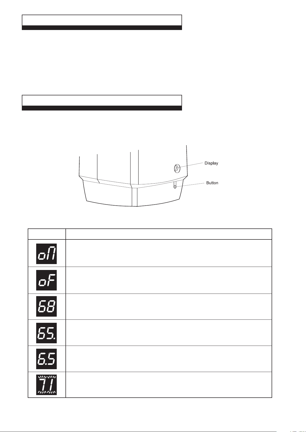
The controls of the solar cylinder are able to indicate working modes on the display. The push button provides the means to
operate the cylinder. During normal operation the system can be turned on and off using the button. When the button is held in for
5 seconds the diagnostic mode will be entered. If this has been done, push the button in for 5 seconds or do not touch it for 10
minutes and the display will return to normal operation.
Fig. 1 - Solar cylinder controls
Display shown Display explained
This indicates the operating mode of the solar system, on or off (on or oF).
Note: It is recommended the system is always left 'ON'.
If oF is shown the solar system is not operating, press the button to change from off to on.
Note: It is recommended the system is always left 'ON'.
This is the temperature of the domestic hot water (°C) in the solar cylinder.
Note: The Solar cylinder temperature can be between 10°C and approximately 70°C max.
When the system is on and working, the display will alternate between the domestic hot
water temperature (for 4 seconds) and the operating mode (o
This is the temperature of the domestic hot water in the solar cylinder.
The flashing dot in the right hand corner of the display shows that the drain back unit pump
and cylinder pump are running.
This is the temperature of the domestic hot water in the solar cylinder.
The flashing dot in the middle of the display shows that only the cylinder pump is running.
n or oF for 2 seconds).
If flashing fault codes (71 to 84). Contact your Installer or Alpha Helpline, Tel: 0870 3001964
Alpha SolarSmart 90 - User Instructions
2
Page 3
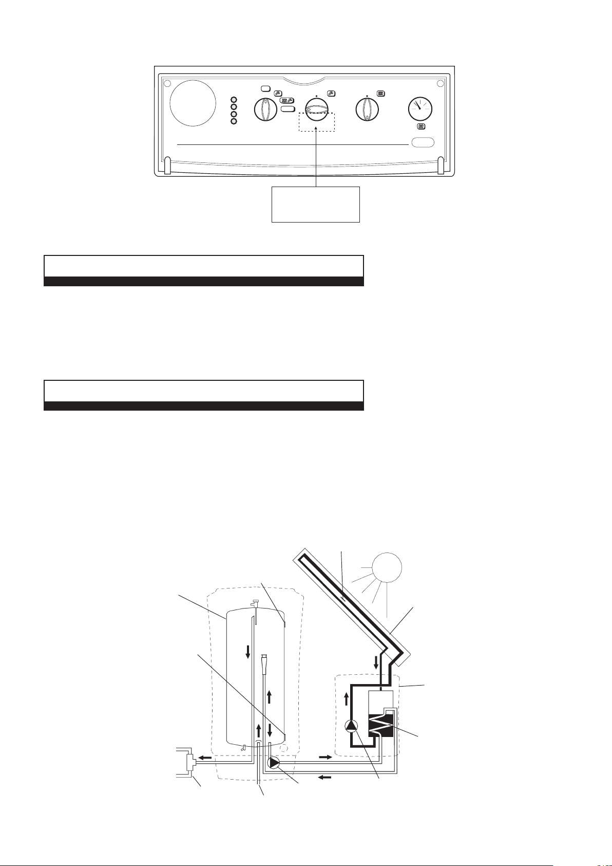
The boiler domestic hot water thermostat must always be set to the maximum setting. A label has been supplied which should
have been positioned over the domestic hot water thermostat knob, as shown below, to ensure the maximum setting is maintained.
OFF
0
A
B
C
D
1
2
RESET
3
SELECTOR THERMOSTAT THERMOSTAT
This Combi boiler is fitted to an
Alpha Solar system and the hot
water thermostat always be
set at maximum (No.9)
1
9
8
5
7
6
IMPORTANT
MUST
2
3
4
1
2
3
9
4
8
5
7
6
2
3
1
04
bar
Fig. 2 - Alpha combination boiler controls
3 POSITIONING OF THE COLLECTOR
The solar energy supplied by a system varies with the orientation and tilt of the collector, which will usually be determined by the
existing roof. However, the predicted variation is slight. For a collector facing anywhere between SE and SW and tilted from the
horizontal by upto 60°, the annual solar energy supplied will be at least 90% of that obtained at the optimum collector position.
It should be remembered that shading from trees, buildings etc., can produce a significant decrease in system performance, and
collectors should be positioned to minimise shading from the sun in the middle of the day.
4 SYSTEM OPERATION
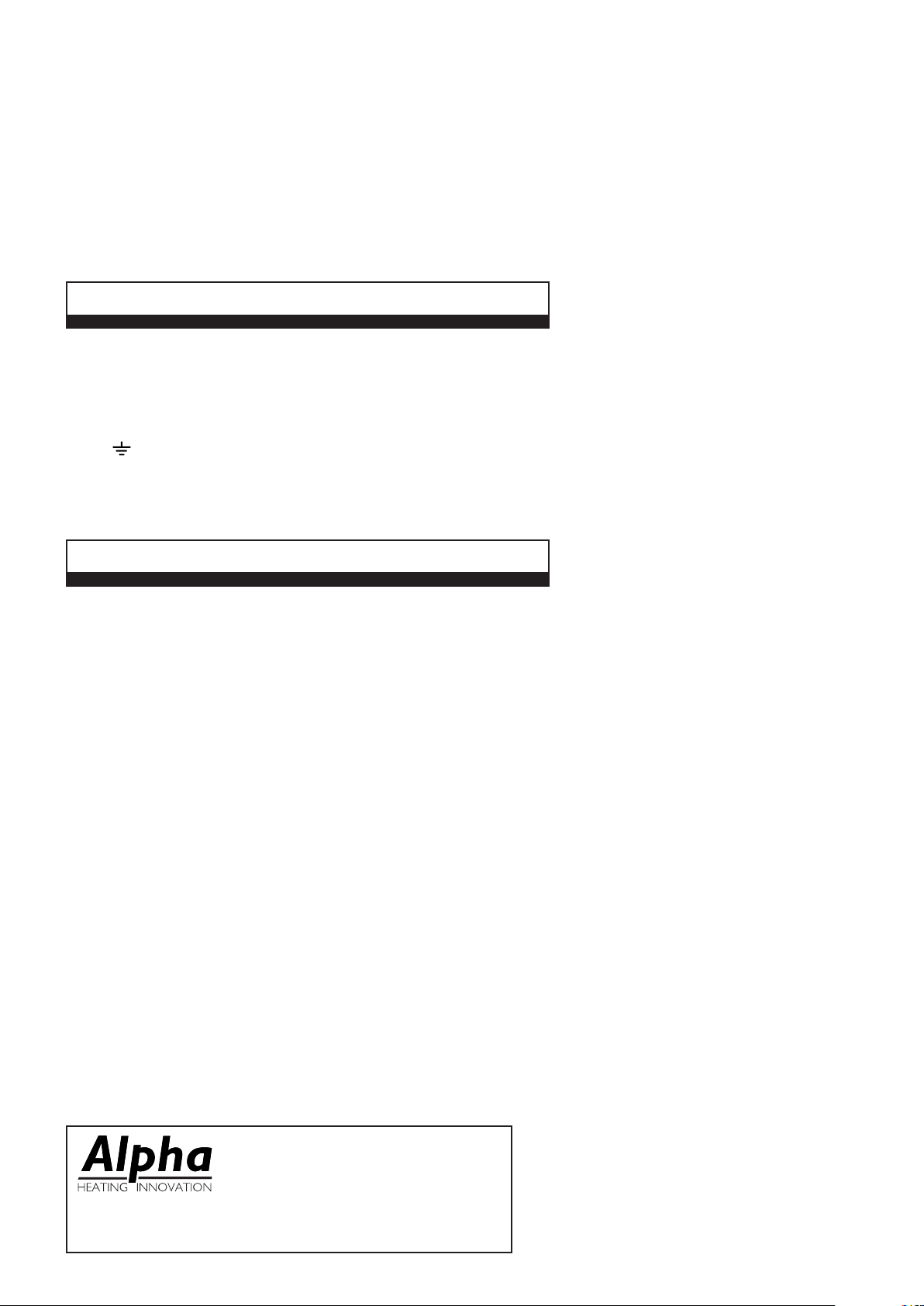
WORKING PRINCIPAL - Fig. 3
The solar collector uses the energy of the natural light to heat the water being circulated around the collector. When the heated water
enters the drain back unit, heat is transfered into the stored water via a heat exchanger coil. Stored domestic hot water is pumped from
the bottom of the solar cylinder through the drain back unit heat exchanger coil where it is heated and returned to the cylinder.
When a hot water tap is turned on mains water flows into the bottom of the solar cylinder and hot water flows out of the top towards
the solar valve at the boiler. If the water from the cylinder is above 60°C the solar valve diverts the flow directly to the tap, if the
temperature is less than 60°C the valve diverts the flow through the combination boiler. When the flow is via the combination boiler
the water temperature is maintained by the boiler. As the temperature of the water entering the boiler is higher than the normal
incoming mains water, less gas is required to heat the water to the set temperature of above 60°C thereby saving energy costs.
Collector sensor
Upper cylinder
temperature sensor
Solar cylinder
Solar collector
Lower cylinder
temperature sensor
Drain back unit
Hot water to taps
Warm water to boiler
Solar valve
Cylinder pump
Mains cold water inlet
Fig. 3
Heat exchanger
Drain back unit
pump
Alpha SolarSmart 90 - User Instructions
3
Page 4
OPERATION OF THE SOLARSMART SYSTEM - Fig.3
When the controls detect a collector sensor temperature that is at least 10°C higher than the lower cylinder sensor and the solar
cylinder temperature is less than 65°C, the drain back unit pump will start. The pump will run at full speed for 250 seconds and then
modulate between 30 and 50% full speed to circulate water around the collector. The speed of the pump is dependent upon the
difference in the temperature between the collector sensor and the lower cylinder sensor.
At the same time that the drain back unit pump starts the cylinder pump will start at 10% full speed to circulate the cylinder water
through the drain back unit heat exchanger. The drain back unit pump will stop when the temperature difference between the
collector sensor and the lower cylinder sensor falls to 3.5°C or the cylinder temperature reaches 70°C. The cylinder pump will
continue to run for 120 seconds to collect any excess heat from the drain back unit then it will also stop.
When both pumps are operating, a flashing dot will be visible in the right hand corner of the display (Fig. 1). If only the cylinder
pump is running, a flashing dot will be visible in the middle of the display.
If a fault occurs, a fault code will be visible in the display.
5 ELECTRICAL SUPPLY
The SolarSmart requires a 230/240 V ~ 50 Hz supply, fused at 3 A if a 13 A 3-pin plug is used or a 5 A fuse if any other type of plug is used.
To connect a plug:-
The colour of the wires in the mains lead of the boiler may not correspond with the coloured markings identifying the terminals in
your plug. In this case proceed as follows:-
The wire coloured green and yellow must be connected to the terminal in the plug that is marked with the letter E, or by the earth
symbol , or coloured green or green and yellow.
The blue wire must be connected to the terminal which is marked with either the letter N or coloured black.
The brown wire must be connected to the terminal which is marked with the letter L or coloured red.
THE APPLIANCE MUST BE EARTHED.
5 IMPORTANT NOTES
1. SOLAR CYLINDER LOCATION
Always ensure the following clearances are available around the cylinder:-
Top: 100 mm, Bottom: 300 mm, Sides: 10 mm, Front: 450 mm
2. MAINS FAILURE
In the event of an electrical supply failure the system will not operate. When the supply is restored, the system will return to normal
operation. If the mains water supply fails, there will be no hot water from the taps.
3. PRESSURE RELIEF VALVES
If the hot water system overheats and steam or water is discharged from the pipe connected to the tundish, turn the Solar system
off and contact your Installer. Your Installer should have told you where these pipes terminate.
4. HOT WATER
To prevent very high temperatures at the hot water taps, the Installer should have fitted a thermostatically controlled mixing valve
after the combination boiler.
5. HOT PIPING
The temperatures of pipework from the collector panel, drain back unit and solar cylinder can be very high. Therefore all Solar
system pipework should have been insulated to not only reduce heat loss, but more importantly to prevent injury from burns.
Ensure your Installer has done this!
6. FROST
Always ensure the room/area where the various parts of the Solar system have been installed are protected from frost.
7. HOLIDAYS
The SolarSmart system uses a very small amount of energy for its operation and more harm can be done by turning the system off.
Therefore, always leave the electrical supply and Solar system switched ON!
8. SERVICING
To maintain efficient and safe operation of the SolarSmart system, it is recommended regular inspection and checks are carried out.
If you contact the Alpha Helpline (Tel: 0870 3001964) for advice, you will be asked for the serial number of your solar cylinder. The
serial number of the cylinder is located on top of the front housing underneath the top cover.
Alpha Therm Limited.
Nepicar House, London Road, Wrotham Heath,
Sevenoaks, Kent TN15 7RS
Tel: 0870 3001964
email: [email protected]
website: www.alpha-boilers.com
Manual compiled and designed by Publications 2000, Tel (01670) 356211 11/07/D213
These instructions have been carefully prepared but
we reserve the right to alter the specification at any
time in the interest of product improvement.
© Alpha Therm Limited 2007.
 Loading...