

Page 1
GEM
Generator Expansion Module
Technical Manual
Effective: April 2008
Alpha Technologies
Page 2

Alpha Technologies
Power
®
Page 3
Generator Expansion Module (GEM)
Technical Manual
745-872-C0-002, Rev. B
Effective Date: April 2008
Copyright© 2008
Alpha Technologies, Inc.
member of The Group
NOTE:
Photographs contained in this manual are for illustrative purposes only. These photographs may not match
your installation.
NOTE:
Operator is cautioned to review the drawings and illustrations contained in this manual before proceeding. If
there are questions regarding the safe operation of this product, please contact Alpha Technologies or your
nearest Alpha representative.
NOTE:
Alpha shall not be held liable for any damage or injury involving its enclosures, power supplies, generators,
batteries, or other hardware if used or operated in any manner or subject to any condition not consistent with
its intended purpose, or is installed or operated in an unapproved manner, or improperly maintained.
TM
To contact Alpha Technologies:
Visit www.alpha.com
or
For general product information and customer service (7 AM to 5 PM, Pacifi c Time), call
1-800-863-3930
For complete technical support, call
1-800-863-3364
7 AM to 5 PM, Pacifi c Time or 24/7 emergency support
To report errors in this document, send email to:
Techpubs@alpha.com
Page 4

Table of Contents
Safety Notes .......................................................................................................................... 6
1.0 Introduction .................................................................................................................8
2.0 Installing the GEM Enclosure ..................................................................................... 9
2.1 Installing the Enclosure Ground Wire .............................................................11
2.2 Installing the Generator.................................................................................. 12
3.0 Operation Using the Line Transfer Switch (LTS) ......................................................13
3.1 Installing the LTS ...........................................................................................13
3.2 Operation ....................................................................................................... 16
4.0 Operation Without Line Transfer Switch ................................................................... 17
4
745-872-C0-002, Rev. B
Page 5

Figures and Tables
Fig. 1-1, Generator Expansion Module..................................................................................8
Fig. 2-1, Mounting Hole Location...........................................................................................9
Fig. 2-2, Ground Wire Hardware Installation ........................................................................11
Fig. 2-3, Drilling Locations for Legacy Enclosures .............................................................. 14
Fig. 4-1, Grounding the Generator ...................................................................................... 17
745-872-C0-002, Rev. B
5
Page 6
Safety Notes
Review the drawings and illustrations contained in this manual before proceeding. If there are any questions
regarding the safe installation or operation of this product, contact Alpha Technologies or the nearest Alpha
representative. Save this document for future reference.
To reduce the risk of injury or death, and to ensure the continued safe operation of this product, the following
symbols have been placed throughout this manual. Where these symbols appear, use extra care and
attention.
ATTENTION:
The use of ATTENTION indicates specifi c regulatory/code requirements that may affect the placement of
equipment and /or installation procedures.
NOTE:
A NOTE provide additional information to help complete a specifi c task or procedure.
CAUTION!
The use of CAUTION indicates safety information intended to PREVENT DAMAGE to material or
equipment.
WARNING!
WARNING presents safety information to PREVENT INJURY OR DEATH to the technician
or user.
6
745-872-C0-002, Rev. B
Page 7

General Safety Precautions
To avoid injury:
• This enclosure and its hardware must only be serviced by authorized personnel.
• The enclosure must remain locked at all times, except when authorized service personnel are present.
• Remove all conductive jewelry or personal equipment prior to servicing equipment, parts, connectors,
wiring, or batteries.
• Read and follow all installation, equipment grounding, usage, and service instructions included in this
manual.
• Use proper lifting techniques whenever handling enclosure, equipment, parts, or batteries.
• Batteries contain dangerous voltages and corrosive material. Battery installation, maintenance, service
and replacement must only be performed by authorized personnel.
• Never use uninsulated tools or other conductive materials when installing, maintaining, servicing or
replacing batteries.
• Use special caution when connecting or adjusting battery cabling. An improperly connected battery cable
or an unconnected battery cable can result in arcing, fi re, or possible explosion.
• Avoid any contact with gelled or liquid emissions from valve-regulated lead-acid (VRLA) batteries.
Emissions contain dilute sulfuric acid that is harmful to the skin and eyes. Emissions are electrolytic, and
are electrically conductive and are corrosive. Follow the Chemical Hazards notes if contact occurs.
• Do not smoke or introduce sparks in the vicinity of batteries or fuel.
• Under certain overcharging conditions, lead-acid batteries can vent a mixture of hydrogen gas that is
explosive. Proper venting of the enclosure is required.
• Follow the battery manufacturer’s approved transportation and storage instructions.
• Avoid contact with the generator exhaust.
To avoid damage:
• Prior to installation, verify the AC input voltage and frequency matches the rating of to the enclosure and
its equipment.
• Prior to installation, verify that the output voltage from the enclosure or its equipment match the voltage
requirements of the connected equipment (load).
• Prior to installation, verify that the enclosure’s utility service panel is equipped with a properly rated circuit
breaker for use with the equipment inside. Refer to manufacturer’s recommendations.
• Review and upgrade utility service panel circuit breaker requirements whenever equipment is changed.
• Prior to installation, contact local utilities, building maintenance departments, and cable/piping locator
services to ensure that installation does not interfere with existing utility cables or piping.
• Do not exceed the output rating of equipment. Verify load requirements prior and during connection
process.
• Prior to handling the batteries, touch a grounded metal object to dissipate any static charge that may have
developed in your body.
Generator Safety Notes
• Installer must check local codes regarding placement of equipment with fl ammable material installed on
utility equipment.
• Never refuel a generator inside an enclosure, or near any source of high heat, spark, or open fl ame. The
generator must be removed from the enclosure and fi lled on the ground.
• The generator produces enough electric power to cause serious electrocution and should only be serviced
by a trained technician.
• Using a generator in wet conditions could result in electrocution. Keep the generator dry.
• The exhaust system, and some generator parts, get hot enough to ignite some materials. Keep the
exhaust area clear of combustible materials.
• The muffl er becomes very hot during operation. Let the generator cool before refueling.
• Do not smoke or allow fl ames or sparks where the generator is refueled or where gasoline is stored.
Refuel in a well ventilated area with the engine stopped.
• Fuel vapors are extremely fl ammable. Clean up any spills before starting the generator.
745-872-C0-002, Rev. B
7
Page 8

1.0 Introduction
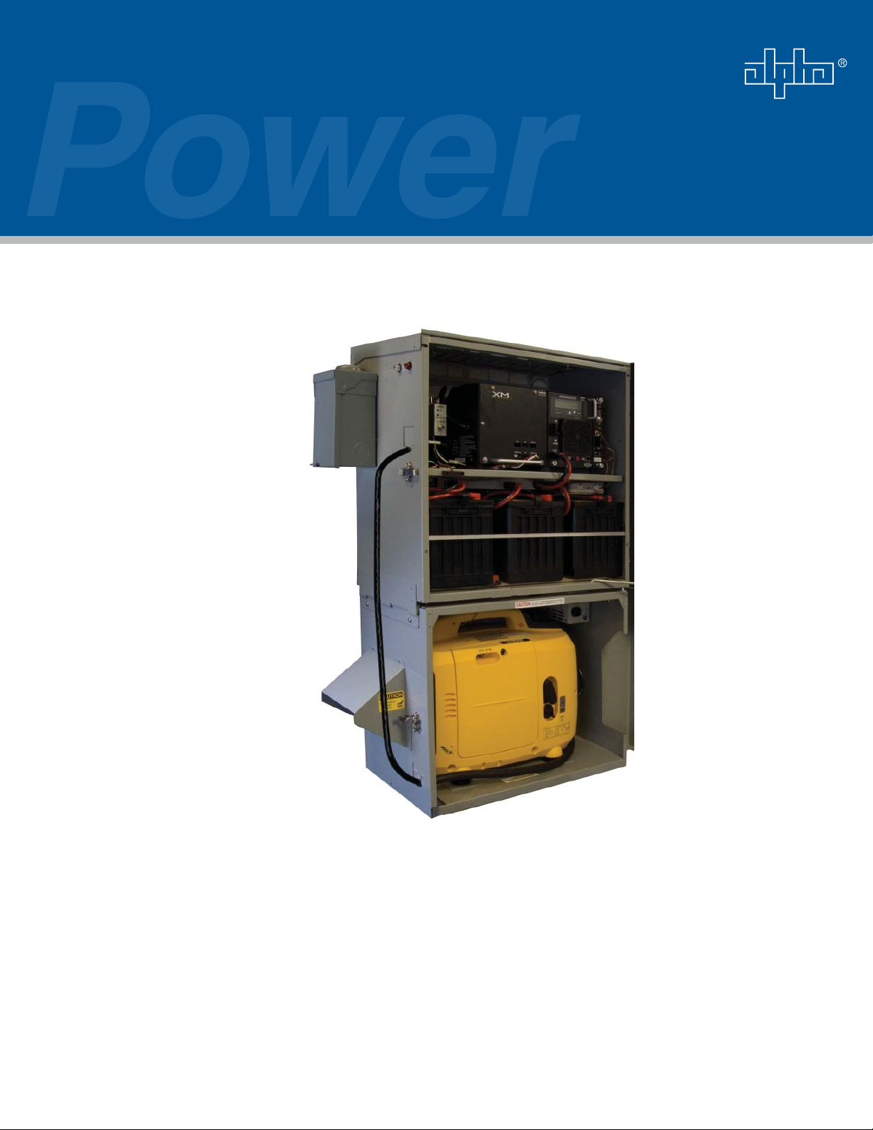
The Generator Expansion Module (GEM) extends runtime for PWE-3 and PWE-6 pole-mount
enclosures. The GEM installs to the base of a PWE enclosure, and shelters and safeguards a
lightweight portable generator. Once the mounting hardware is in place, the GEM can be quickly
removed or re-installed without tools.
The generator can be connected to the power supply using an optional Line Transfer Switch (LTS)
that switches the power source from generator to line automatically on resumption of AC line power.
The GEM can be deployed independently, or as a part of Alpha’s Generator Expansion Module
system, which includes the GEM enclosure, mounting kit, line transfer switch (LTS), and portable
generator.
Key Features:
• Quick installation
• Optional Line Transfer Switch (LTS)
• Provides four to ten hours of additional runtime
• Protects generator from weather and theft
• Field-installable on existing PWE-3 and PWE-6 enclosures
• Can be left in place or easily removed after an outage
Mounting Slide
Rails
Exhaust Hood / Rain
Guard
Generator Expansion
Module
Portable Generator
Fig. 1-1, Generator Expansion Module (GEM)
8
745-872-C0-002, Rev. B
Page 9

2.0 Installing the GEM Enclosure
The GEM enclosure mounts underneath existing PWE-3 pole-mounted enclosures, and provides for
secure deployment of an AC generator.
Tools and Materials:
Drill with 3/16" and 1/4" bits• Rivet gun•
Two 1/4"-20 Nylok nuts (provided)• Four .188" rivets (provided)•
#2 Phillips screw driver• Center punch (for some enclosures)•
7/16" open end wrench• Tin Snips (for some enclosures)•
1. Locate the mounting holes on the lower left and right side of the PWE enclosure. Use the 1/4" drill
bit to clear the powdercoat from the holes. If there are no mounting holes on your enclosure, drill
a 1/4" hole using the dimensions shown in Fig. 2-1. Mount the GEM brackets to the PWE using
these holes. Secure the brackets with the 1/4" Nylok nuts.
Tape measure (for some enclosures)•
Nylok
Nut
CAUTION!
Take great care in measuring and drilling holes (when necessary). Hole location is critical.
3/8"
6 3/4"
(both sides)
745-872-C0-002, Rev. B
Fig. 2-1, Mounting Hole Location
9
Page 10

2.0 Installation, continued
2. Position the bracket so both .2" half shears are equally spaced and hanging below the bottom of
the enclosure. Using the mounting bracket as a template, use a 3/16" (.188") drill bit to drill two
holes in each side of the enclosure wall. Rivet the bracket in place using the provided .188" rivets.
Ensure equal spacing of
half shears.
3. Open the PWE enclosure and secure the door open. Slide the GEM into the bracket grooves.
NOTE:
The fi rst half of the bracket will slide in until hitting a stop. At that point, lift the front edge of the GEM to free
the enclosure and slide it the rest of the way in.
4. Verify the brackets are correctly seated. Line up the fl oating nuts on the left and right mounting
brackets with the PEM thumb screws located inside the GEM. Secure the screws.
Drill. Rivet in place.
CAUTION!
Verify the brackets are properly seated and the PEM thumb screws are securely fastened. If the
PEM thumb screws do not line up with the nuts in the mounting brackets, the enclosure is not
properly seated.
10
745-872-C0-002, Rev. B
Page 11

2.0 Installation, continued
2.1 Installing the Enclosure Ground Wire
1. Slide the battery slide tray out and verify the area behind the drilling location is clear of
wiring or equipment. Drill a 1/4" hole in the side of the PWE enclosure and collect metal
shavings.
CAUTION!
Before drilling, verify the area behind is free from batteries, wiring, or equipment.
2. Slide the battery tray back in. Install the mounting hardware and ground wire as shown
below.
Enclosure Wall
Wing Nut
Ground Wire
Split Washer
Nut
External Tooth
Lock Washer
Fig. 2-2, Ground Wire Hardware Installation
3. Connect the terminal end of the enclosure ground wire to the 1/4-20" stud located on the
left side of the GEM enclosure and secure with the provided 1/4" nut.
External Tooth
Lock Washer
1/4-20 Bolt
745-872-C0-002, Rev. B
11
Page 12

2.0 Installation, continued
2.2 Installing the Generator
Place the generator in the enclosure with its feet inside the foot recesses. Secure the
generator handle with the provided safety lanyard.
Safety Lanyard
WARNING!
The generator must be secured inside the enclosure with the supplied safety lanyard.
Failure to do so could result in injury or death.
12
745-872-C0-002, Rev. B
Page 13

3.0 Operation Using the Line Transfer Switch (LTS)
Alpha's recommended confi guration of the GEM enclosure uses a line transfer switch. The LTS
automatically switches the power supply's power source back to AC line on resumption of utility
power. In cases of intermittent power, the LTS will alternate from generator to AC line power as
available.
3.1 Installing the LTS
1. Clean the area where the Line Transfer Switch (LTS) will be installed. Remove the
adhesive backing from the LTS and install in the PWE enclosure.
2. Route the generator cord out of the PWE enclosure through the PWE's generator access
door.
745-872-C0-002, Rev. B
13
Page 14

3.0 Operation Using the Line Transfer Switch (LTS), continued
3.1 Installing the LTS, continued
3. If the enclosure does not have a generator door, drill a 2-1/2" hole in the side of the
enclosure as shown in Fig. 2-3. Alpha recommends using a 2-1/2" Punch Kit (Alpha P/N
745-131-20) and a grommet with plug (Alpha P/N 745-131-21) with this modifi cation.
CAUTION!
Before drilling, verify the areas behind the drilling locations are free from batteries, wiring, or
equipment.
PWE Thermal
PWE Classic
PWE-V
14
3.75"
10.00"
10.00"
21.75"
10.50"
9.50"
Fig. 2-3, Drilling Locations for Legacy Enclosures
745-872-C0-002, Rev. B
Page 15

3.0 Operation Using the Line Transfer Switch (LTS), continued
3.1 Installing the LTS, continued
4. Route the cord into the GEM enclosure through the generator access door and connect
to the generator output. Secure with the rubber grommet.
Rubber Grommet
5. Connect the Primary Utility plug from the LTS into the utility outlet and plug the power
supply power cord into the LTS.
Power Supply Power Cord
To Primary Utility Outlet
To Generator
NOTE:
Confi guration of components in PWE enclosures will vary. Make sure the Primary Utility Cord from the LTS
reaches an open outlet prior to installing.
745-872-C0-002, Rev. B
15
Page 16

3.0 Operation Using the Line Transfer Switch (LTS), continued
3.2 Operation
1. Refer to the generator's operation manual and start the generator.
2. Check operation of the power supply. Ensure input current to the power supply does not
exceed the generator's rating.
• Kipor (IG2000)= 12A (derated @ 1400W)
• Honda (EU2000i) = 13.3A (rated @ 1600W)
3. When proper operation is verifi ed, close the PWE and GEM enclosures.
CAUTION!
The Alpha XM2 power can draw an additional 400W during battery charging operation. If the
combined load exceeds the generator's listed rating, turn the power supply DC breaker OFF to
avoid an over current condition.
NOTE:
Turning off the DC breaker while the power supply is in inverter mode will cause the load to be dropped.
Ensure the power supply is in normal operation before turning off the battery breaker
16
745-872-C0-002, Rev. B
Page 17

4.0 Operation Without Line Transfer Switch
The following procedure is for operating a generator in the GEM enclosure without a line transfer
switch. Alpha recommends using an LTS for effi cient operation of the powering system.
1. Connect a ground wire from the generator ground screw to the ground stud on the back wall of
the GEM enclosure.
2. Using a 10' outdoor rated (SJW) extension cord (minimum wire gauge for 120Vac is 12AWG),
connect the generator to the power supply's input line cord. The cord is routed through the
generator access doors located on the left side of the PWE and GEM enclosures.
3. Refer to the generator's operation manual and start the generator.
4. Check operation of the power supply. Ensure input current to the power supply does not exceed
the generator's rating.
• Kipor (IG2000)= 12A (derated @ 1400W)
• Honda (EU2000i) = 13.3A (rated @ 1600W)
CAUTION!
The Alpha XM2 power can draw an additional 400W during battery charging operation. If the
combined load exceeds the generator's listed rating, turn the power supply DC breaker OFF to
avoid an over current condition.
5. When proper operation is verifi ed, close the PWE and GEM enclosures.
Honda EU2000i Kipor IG2000
GEM Ground Stud
745-872-C0-002, Rev. B
Fig. 4-1, Grounding the Generator
17
Page 18

Page 19

Alpha Technologies
Power
Copyright © 2008 Alpha Technologies, Inc. All rights reserved. Alpha is a registered trademark of Alpha Technologies. 745-872-C0-002, Rev. B.
Due to continuing product improvements, Alpha reserves the right to change specifi cations without notice.
®
Alpha Technologies
3767 Alpha Way
Bellingham, WA 98226
USA
Tel: +1 360 647 2360
Fax: +1 360 671 4936
Web: www.alpha.com
Alpha Technologies Ltd.
4084 McConnell Court
Burnaby, BC, V5A 3N7
CANADA
Tel: +1 604 430 1476
Fax: +1 604 430 8908
Alpha Technologies
Europe Ltd.
Twyford House
Thorley
Bishop's Stortford
Hertfordshire
CM22 7PA
UNITED KINGDOM
Tel: +44 0 1279 501110
Fax: +44 0 279 659870
Alpha Technologies GmbH
Hansastrasse 8
D 91126 Schwabach
GERMANY
Tel: +49 9122 79889 0
Fax: +49 9122 79889 21
Alphatec, Ltd
P.O. Box 56468
Limassol, Cyprus
CYPRUS
Tel: +357 25 375675
Fax: +357 25 359595
AlphaTEK ooo
Khokhlovskiy Pereulok 16
Stroenie 1
109028 Moscow
RUSSIA
Tel: +7 495 916 1854
Fax: +7 495 916 1349
Alphatec Baltics
S. Konarskio Street 49-201
LT-03123 Vilnius
LITHUANIA
Tel: +370 5 210 5291
Fax: +370 5 210 5292
Alpha Technologies
34, Grande Rue
Bétheny F-51450
FRANCE
Tel: +33 32 64990 54
Fax: +33 95 60205 01
 Loading...