

Page 1
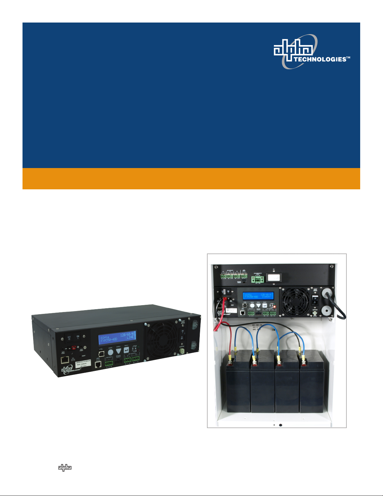
Alpha FXM350/ Micro350 UPS
Installation and Operation
Manual
Part # 017-241-B0
Effective 11/11
member of The Group
™
Your Power Solutions Partner
Page 2

Page 3

Alpha FXM350 and Micro350 UPS
Installation and Operation Manual
NOTE:
Photographs contained in this manual are for illustrative purposes only. These photographs may not match your installation.
NOTE:
Operator is cautioned to review the drawings and illustrations contained in this manual
before proceeding. If there are questions regarding the safe operation of this powering
system, contact Alpha Technologies or your nearest Alpha representative.
NOTE:
Alpha shall not be held liable for any damage or injury involving its enclosures, power
supplies, generators, batteries, or other hardware if used or operated in any manner or
subject to any condition inconsistent with its intended purpose, or if installed or operated in an unapproved manner, or improperly maintained.
For technical support, contact Alpha Technologies:
Canada and USA: 1-888-462-7487
International: +1-604-436-5547
Email: support@alpha.ca
Copyright
Copyright © 2011 Alpha Technologies Ltd. All rights reserved. Alpha is a registered trademark of Alpha Technologies.
No part of this documentation shall be reproduced, stored in a retrieval system, translated, transcribed, or
transmitted in any form or by any means manual, electric, electronic, electromechanical, chemical, optical, or
otherwise without prior explicit written permission from Alpha Technologies.
This document, the software it describes, and the information and know-how they contain constitute the proprietary, confidential and valuable trade secret information of Alpha Technologies, and may not be used for
any unauthorized purpose, or disclosed to others without the prior written permission of Alpha Technologies.
The material contained in this document is for information only and is subject to change without notice.
While reasonable efforts have been made in the preparation of this document to assure its accuracy, Alpha
Technologies assumes no liability resulting from errors or omissions in this document, or from the use of the
information contained herein. Alpha Technologies reserves the right to make changes in the product design
without reservation and without notification to its users.
Page 4

Table of Contents
1. Safety ....................................................................................................................................7
1.1 Safety Symbols .................................................................................................................... 7
1.2 General Warnings ................................................................................................................ 8
1.3 Battery Safety ....................................................................................................................... 8
1.4 Work Environment Safety .................................................................................................... 9
1.5 Certications and Compliances .......................................................................................... 10
2. General Description ............................................................................................................11
2.1 Alpha FXM350 .....................................................................................................................11
2.2 Micro350/ Alpha FXM350 ....................................................................................................11
2.3 FXM350 Front Panel .......................................................................................................... 13
2.4 Micro350 Top Panel ........................................................................................................... 16
3. Site Planning .......................................................................................................................17
3.1 Safety Precautions ............................................................................................................. 17
3.2 Electromagnetic Compatibility (EMC) Requirements ......................................................... 18
3.3 Mounting Options for the Micro350 (XL and XL3) .............................................................. 18
3.4 Options for Communicating with the FXM .......................................................................... 22
4. Unpacking the Equipment ...................................................................................................23
4.1 Alpha FXM350/Micro350 Conguration ............................................................................. 23
4.2 Unpacking .......................................................................................................................... 23
4.3 Optional Items .................................................................................................................... 23
5. Installation ..........................................................................................................................24
5.1 Installation of the Micro350 ................................................................................................ 24
5.2 Mounting and Wiring the FXM350 as a standalone device ................................................ 31
5.3 Wiring the External Batteries and Optional Battery Heater Mats ....................................... 33
5.4 Start-Up .............................................................................................................................. 35
6. Theory of Operation ............................................................................................................36
6.1 Block Diagram .................................................................................................................... 36
6.2 Modes of Operation ............................................................................................................ 36
2
017-241-B0 Rev B
Page 5

7. Operating the FXM350........................................................................................................40
7.1 Switching the Alpha FXM On and Off ................................................................................. 40
7.2 Operating from the Control Panel Interface ....................................................................... 42
7.3 Operating via the FXM Communication Module (Intranet or Internet) ............................... 49
7.4 The Alpha UPS Monitor Interface ....................................................................................... 73
7.5 HyperTerminal Interface ..................................................................................................... 76
8. Maintenance .......................................................................................................................89
8.1 Updating the Software ........................................................................................................ 89
8.2 Testing and Replacing the Batteries ................................................................................... 92
8.3 Preventive Maintenance ..................................................................................................... 95
9. Troubleshooting ..................................................................................................................96
9.1 Procedure ........................................................................................................................... 96
10. Specications ....................................................................................................................98
11. Warranty ..........................................................................................................................101
12. Emergency Shutdown Procedure ...................................................................................102
List of Figures
Figure 1 — Micro350 cabinets ..................................................................................................11
Figure 2 — FXM350 mounted in a standard Micro350 cabinet................................................. 12
Figure 3 — FXM 350 front panel description ............................................................................ 13
Figure 4 — User input layout ................................................................................................... 14
Figure 5 — Contact Layout (Standard for C1 and C2) .............................................................. 15
Figure 6 — Micro350 Top Panel ................................................................................................ 16
Figure 7 — Mounting the Micro350 ........................................................................................... 18
Figure 8 — Mounting on optional pedestal ............................................................................... 19
Figure 9 — FXM350 Mounting Dimensions .............................................................................. 20
Figure 10 — Rack-mount options ............................................................................................. 20
Figure 11 — FXM350 with ears for rack mounting .................................................................... 21
Figure 12 — Alpha FXM Communication Options .................................................................... 22
Figure 13 — Mounting to a wooden pole .................................................................................. 25
Figure 14 — Securing the enclosure to the mounting bracket .................................................. 25
017-241-B0 Rev B
3
Page 6

Figure 15 — Attaching the mounting bracket to the wall studs ................................................. 27
Figure 16 — AC Power distribution terminal blocks .................................................................. 28
Figure 18 — Terminal block wiring ............................................................................................ 29
Figure 17 — Wiring the Micro350 ............................................................................................. 29
Figure 19 — Ferrite ring installed on RJ45 network cable ........................................................ 30
Figure 20 — FXM350 with rack-mount ears and signal assembly option (wiring box not shown)
........................................................................................................................................ 31
Figure 21 — FXM350 Electrical Connections ........................................................................... 32
Figure 22 — External Battery Wiring (for 48 VDC string (top) and 24 VDC string) ................... 33
Figure 23 — Securing the batteries with the optional restraining bar ....................................... 34
Figure 24 — FXM 350 block diagram ....................................................................................... 36
Figure 25 — Battery charging in line mode ............................................................................... 38
Figure 26 — Back up power from batteries ............................................................................... 38
Figure 27 — LCD Control Panel Logo Screen .......................................................................... 42
Figure 28 — LCD Menu Tree .................................................................................................... 44
Figure 29 — Web GUI (UPS Specication Screen shown) ....................................................... 49
Figure 30 — Alpha UPS Monitor: UPS Communications screen .............................................. 50
Figure 31 — Web GUI: UPS Specication screen .................................................................... 51
Figure 32 — Web GUI: Input & Output screen .......................................................................... 52
Figure 33 — Web GUI: Battery & Inverter screen ..................................................................... 52
Figure 35 — Web GUI: User Input Status screen ..................................................................... 53
Figure 34 — Web GUI: Relay & Load Shed screen .................................................................. 53
Figure 36 — UPS Maintenance: Unit Conguration screen ...................................................... 54
Figure 37 — Restore all default commands .............................................................................. 54
Figure 38 — UPS Maintenance: Battery screen ....................................................................... 56
Figure 39 — UPS Maintenance: Inverter screen ...................................................................... 57
Figure 40 — UPS Maintenance: Relay & Load Shed screen.................................................... 58
Figure 41 — Programmable Timer Operation ........................................................................... 59
Figure 42 — Time Of Day Action Operation .............................................................................. 59
Figure 43 — Time Of Day Conguration ................................................................................... 60
Figure 44 — Time Of Day Action Status ................................................................................... 60
Figure 45 — Assigning the Temperature trigger function to a dry contact – Alpha UPS Monitor
4
017-241-B0 Rev B
Page 7

........................................................................................................................................ 61
Figure 46 — Setting the Temperature trigger value .................................................................. 61
Figure 47 — UPS Maintenance: Time & Date screen ............................................................... 62
Figure 48 — UPS Maintenance: Password screen ................................................................... 62
Figure 49 — User Input Conguration: Setting the Trigger Type .............................................. 63
Figure 50 — User Input Conguration: Setting the Logic Level ................................................ 63
Figure 51 — User Input Conguration: Setting an Action ......................................................... 64
Figure 52 — User Input Current Status ..................................................................................... 64
Figure 53 — User Input Current Status ..................................................................................... 64
Figure 54 — Alarms & Faults screen ........................................................................................ 65
Figure 55 — Event History screen ............................................................................................ 65
Figure 56 — Event Log Monitor screen .................................................................................... 66
Figure 57 — Event Log Monitor, Open Event File window........................................................ 67
Figure 58 — Alpha UPS Monitor: Upgrade Firmware ............................................................... 67
Figure 59 — Upgrade Communication Module ......................................................................... 68
Figure 60 — Alpha UPS Monitor: Congure Site Information ................................................... 68
Figure 61 — Congure SNMP screen ....................................................................................... 69
Figure 62 — Email Notication screen ...................................................................................... 69
Figure 63 — Test email feature ................................................................................................. 70
Figure 64 — Alpha UPS Monitor (UPS Specication Screen shown) ....................................... 73
Figure 65 — Add or Remove Programs Window ...................................................................... 74
Figure 66 — HyperTerminal communication parameters ......................................................... 76
Figure 67 — Main Menu Screen ............................................................................................... 77
Figure 68 — Menu Tree ............................................................................................................ 78
Figure 69 — Temperature trigger function via HyperTerminal ................................................... 84
Figure 70 — Typical Discharge Characteristics for Lead Acid Batteries ................................... 92
Figure 71 — Battery string example ........................................................................................ 104
Figure 72 — Edge Trigger ....................................................................................................... 106
Figure 73 — Level Trigger ....................................................................................................... 106
Figure 74 — Level Alternative ................................................................................................ 107
017-241-B0 Rev B
5
Page 8

List of Tables
Table A — UPS Operating Modes ......................................................................................................... 43
Table B — Control Menu ....................................................................................................................... 45
Table C — System Status Menu ........................................................................................................... 47
Table D — List of Parameters ............................................................................................................... 55
Table E — Line Status (see Figure 67) ................................................................................................. 79
Table F — Output Status (see Figure 67) ............................................................................................. 79
Table G — Faults (see Figure 67) ......................................................................................................... 80
Table H — Alarms (see Figure 67) ........................................................................................................ 80
Table I — Maintenance Submenu ......................................................................................................... 81
Table J — Dry Contact Conguration Settings...................................................................................... 82
Table K — Setting the Timer Contact .................................................................................................... 83
Table L — Setting the Date and Time ................................................................................................... 85
Table M — Event Codes ....................................................................................................................... 87
Table N — Battery Temperature Compensation Values ........................................................................ 93
Table O — Alarm Submenu .................................................................................................................. 96
Table P — Fault Submenu .................................................................................................................... 97
Table Q — Problems Not Reported by System..................................................................................... 97
Table R — Mechanical Specications ................................................................................................... 98
Table S — Electrical Specications....................................................................................................... 99
Table T — Boost/Buck/Line Transfer Thresholds ................................................................................ 100
Table U — Regulatory ......................................................................................................................... 100
6
017-241-B0 Rev B
Page 9
1. Safety
SAVE THESE INSTRUCTIONS: This manual contains important safety instructions
that must be followed during the installation, servicing, and maintenance of the product. Keep it in a safe
place. Review the drawings and illustrations contained in this manual before proceeding. If there are any
questions regarding the safe installation or operation of this product, contact Alpha Technologies or the nearest Alpha representative. Save this document for future reference.
1.1 Safety Symbols
To reduce the risk of injury or death, and to ensure the continued safe operation of this product, the following
symbols have been placed throughout this manual. Where these symbols appear, use extra care and attention.
The use of ATTENTION indicates specic regulatory/code requirements that may affect the
placement of equipment and /or installation procedures.
NOTE:
A NOTE provides additional information to help complete a specic task or procedure.
Notes are designated with a checkmark, the word NOTE, and a rule beneath which the
information appears.
CAUTION!
CAUTION indicates safety information intended to PREVENT DAMAGE to material or
equipment. Cautions are designated with a yellow warning triangle, the word CAUTION,
and a rule beneath which the information appears.
WARNING!
WARNING presents safety information to PREVENT INJURY OR DEATH to personnel.
Warnings are indicated by a shock hazard icon, the word WARNING, and a rule beneath
which the information appears.
HOT!
The use of HOT presents safety information to PREVENT BURNS to the technician or
user.
017-241-B0 Rev B
7
Page 10

1.2 General Warnings
You must read and understand the following warnings before installing the product. Failure to do so could
result in personal injury or death.
• Read and follow all instructions included in this manual.
• Only qualified personnel are allowed to install, operate and service this system and its components.
CAUTION!
Risk of Electric Shock. See Installation Instruction before connecting to the supply.
• The FXM350/ Micro350 is only intended for restricted access locations
• The UPS shall be connected only to a dedicated branch circuit.
CAUTION!
To reduce the risk of re, connect only to a maximum branch circuit overcurrent protection in accordance with the National Electrical Code, ANSI/NFPA 70.
• Always assume electrical connections or conductors are live. Switch all circuit breakers and double
check connections with a voltmeter before performing installation or maintenance.
• A disconnect switch shall be provided by others for the AC input and AC output circuits.
• The branch circuit overcurrent protection for the AC input and AC output circuit shall be provided in the
end installation.
• Place warning label(s) on the utility panel to tell emergency personnel that a UPS is installed.
• Use only proper lifting techniques whenever handling equipment, parts, or batteries.
• Ferules or the equivalent must be used when stranded wire is used on the AC input and output terminal
blocks.
WARNING!
The Alpha FXM350/ Micro350 have more than one live input circuit. AC power may be
present at the outputs even if the system is disconnected from line or battery power.
CAUTION!
The Alpha FXM350/ Micro350 metal surfaces can be very hot to the touch.
1.3 Battery Safety
• Battery Installation and servicing should be performed or supervised by personnel knowledgeable about
batteries and the required precautions performed.
• Be extra cautious when connecting or adjusting battery cabling. An improperly connected battery cable
or an unconnected battery cable can result in arching, fire or explosion.
• Before attaching the batteries to the Alpha FXM350/ Micro350, make sure that the polarity is correct.
• Use new batteries when installing a new unit. Verify that all batteries are the same type with identical
date codes.
• When replacing batteries, use sealed lead acid batteries, rated 12 V. Never install old or untested batteries.
• Batteries that show signs of cracking, leaking or swelling must be replaced immediately by authorized
personnel using a battery of identical type and rating.
8
017-241-B0 Rev B
Page 11

CAUTION!
Never open, damage or mutilate batteries. Released Electrolyte is harmful to the skin
and eyes. It may be toxic and hazardous to the environment.
• Never dispose of batteries in a fire. The batteries may explode. Follow the manufacturer’s directions and
check with your local jurisdictions for safe battery disposal.
• If electrolyte splashes on your skin, immediately wash the affected area with water. If electrolyte gets into
your eyes, wash them for at least 10 minutes with clean running water or special neutralizing eye wash
solution. Seek medical attention at once.
• Neutralize spilled electrolyte with special neutralizing solution and a “spill kit” or solution of 1 lbs
(0.45KG) of baking soda (bicarbonate of soda) in 1 gallon (3.8 L) of water.
CAUTION!
A battery can present a risk of electrical shock and high short-circuit current. The following precautions should be observed when working on batteries:
a. Remove watches, rings, or other metal objects.
b. Use tools with insulated handles.
c. Wear rubber gloves and boots.
d. Do not lay tools or metal parts on top of batteries.
e. Disconnect the charging source before connecting or disconnecting battery terminals.
f. Determine if the battery is inadvertently grounded. If inadvertently grounded, remove the source from
the ground. Contact with any part of a grounded battery can result in electrical shock. The likelihood
of such shock can be reduced if the grounds are removed during installation and maintenance
(applicable to equipment and remote battery supplies not having a grounded supply circuit).Never
let live battery wires touch the Alpha FXM350/ Micro350, the enclosure or any other metal objects.
This can cause a fire or explosion.
• Do not smoke or introduce sparks in the vicinity of a battery.
• If the batteries have been in storage for more than 3 months, recharge them for at least 24 hours and
then test them with a load before installation.
• Each AlphaCellTM battery has a date code found on the warning label which must be recorded in the
maintenance log. If non-Alpha batteries are used, see the manufacturer’s documentation for date code
type and placement.
1.4 Work Environment Safety
• Do not work alone under hazardous conditions.
• Keep the chassis area clear and dust-free during and after the installation.
• Keep tools away from walk areas where you or others could fall over them.
• Wear safety glasses when working under any conditions that might be hazardous to your eyes.
• Do not work on the unit or connect or disconnect cables during periods of lightning activity.
017-241-B0 Rev B
9
Page 12

1.5 Certifications and Compliances
The Alpha FXM350 and Micro350, has been designed, manufactured, and tested to the requirements of the
following national and international safety standards:
• CAN/CSA-C22.2 No. 107.3-05 – Uninterruptible Power Systems; additional requirements (RD): CAN/
CSA-C22.2 No. 60950-1-03 - Information Technology Equipment - Safety.
• UL 1778 (Edition 4) – Uninterruptible Power Systems; additional requirements (RD): UL 60950-1 (Edition
1) - Information Technology Equipment - Safety.
• FCC CFR47 Part 15 Class A – This equipment has been tested and found to comply with the limits for a
Class A digital device pursuant to part 15 of the FCC Rules. These limits are designed to provide reasonable protection against harmful interference when the equipment is operated in a commercial environment. This equipment generates, uses, and can radiate radio frequency energy and, if not installed and
used in accordance with the instruction manual, may cause harmful interference to radio communications. Operation of this equipment in a residential area is likely to cause harmful interference in which
case the user will be required to correct the interference at his own expense.
• Industry Canada - This Class A digital device apparatus complies with Canadian ICES-003.
• Industry Canada - Cet appareil numrique de la Classe A est conformé la norme NMB-003 du Canada.
10
017-241-B0 Rev B
Page 13
2. General Description
2.1 Alpha FXM350
The Alpha FXM350 is available in 24Vdc and 48Vdc models. It provides up to 350W of regulated AC Power
to the load, when utility power is available, and provides back up power from the batteries in case of a utility
power failure. Noteworthy features include:
• Local or remote monitoring and control via USB and SNMP communication
• Small footprint for wall, rack or enclosure mounting
• Dependable operation in extreme operating environments (-40 to 74°C or -40 to 165°F)
• Powerful firmware with enhanced features such as battery run-time information
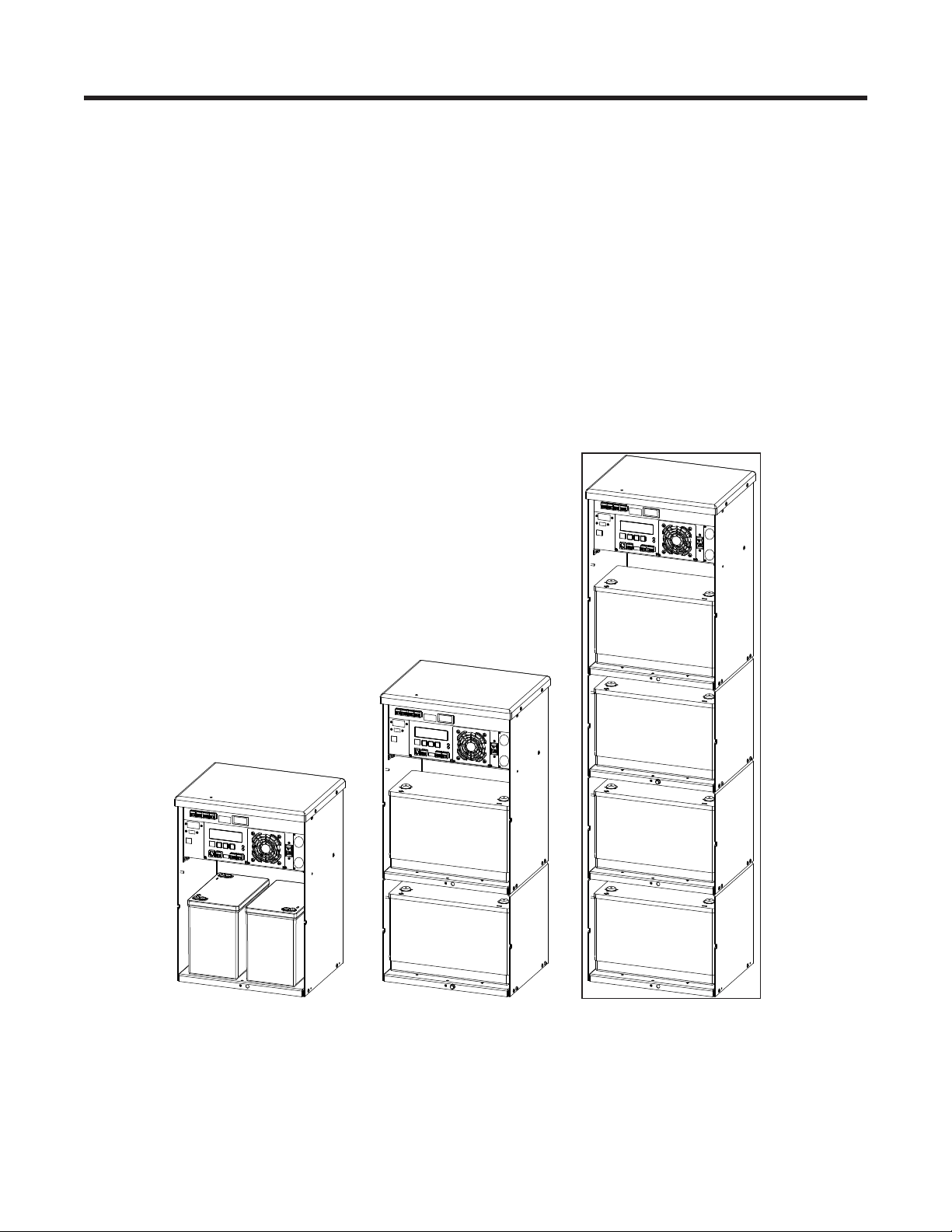
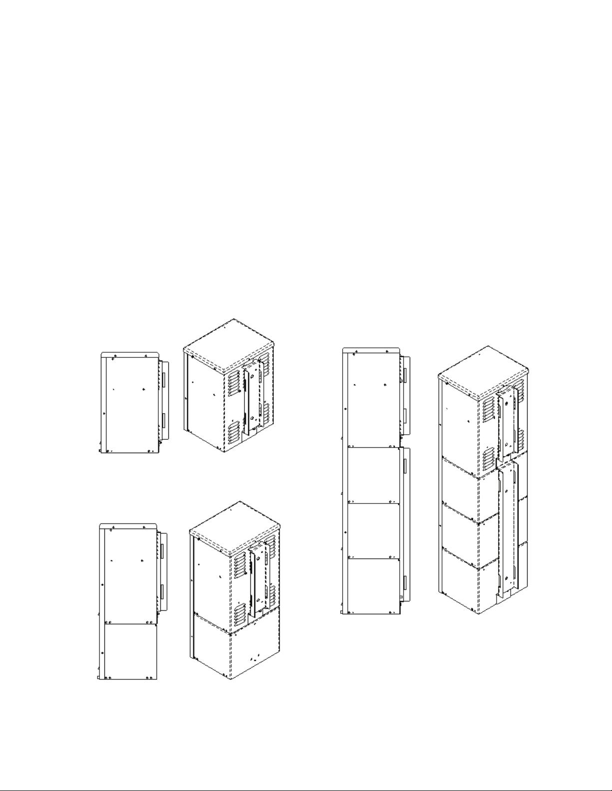
2.2 Micro350/ Alpha FXM350
The Micro350 contains a standard FXM350 along with batteries—Figure 1 shows three options for the enclosure. These enclosures are designed with a NEMA 3R rating for outdoor applications.
Figure 2 shows the FXM350 installed in a standard-sized Micro350 cabinet. Power is distributed through
terminal blocks mounted on a DIN rail.
(a)Standard Micro350
(1 battery tray)
017-241-B0 Rev B
(b) Micro350 XL
(2 battery trays)
Figure 1 — Micro350 cabinets
(c) Micro350 XL3
(4 battery trays)
11
Page 14
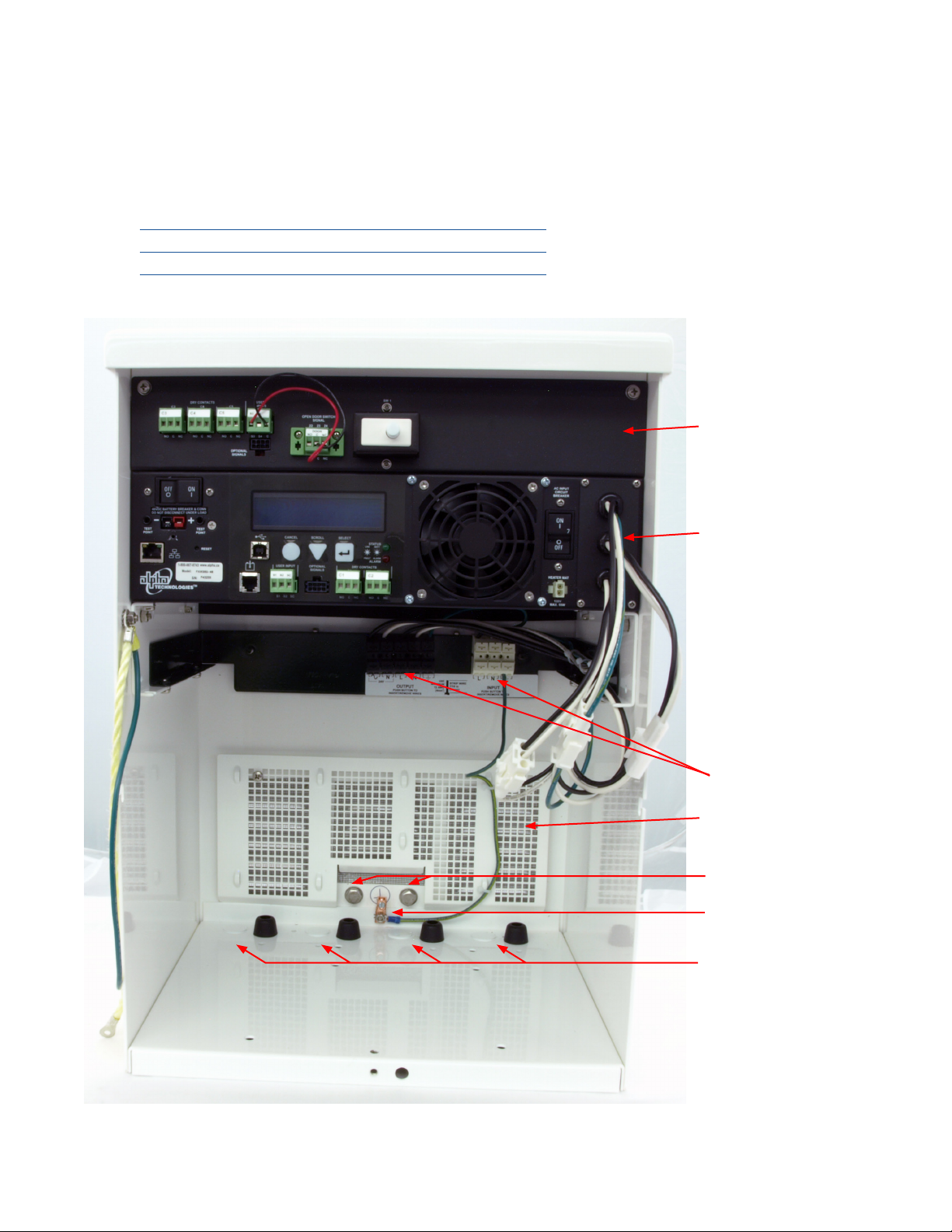
In addition to the FXM350 standard features, the unit also includes the following:
• Three additional user-configurable dry contacts and two additional user inputs (top panel in Figure 2)
• Door sensor switch for increased security
• AC Input and outputs on an easy to install terminal block
• Flexible dual AC and DC output for multiple loads up to 350W with distribution
AC input Battery bus voltage AC output (dual)
120Vac 48V or 24V 120/24Vac
230Vac 24V 230/24Vac
Micro350 top panel
FXM350 front panel
AC power distribution
terminal blocks
Wire management
panel
Attachment holes for
mounting bracket
Ground stud
Knockouts for wiring
12
Figure 2 — FXM350 mounted in a standard Micro350 cabinet
017-241-B0 Rev B
Page 15
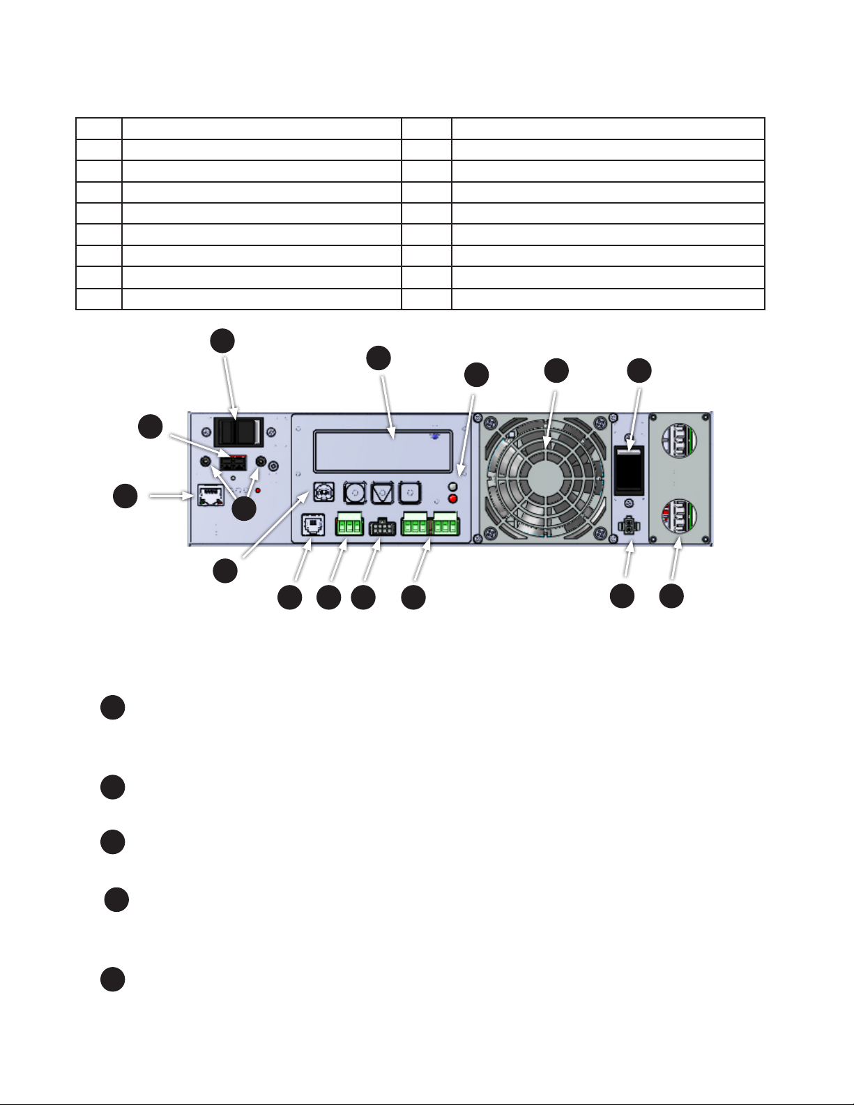
2.3 FXM350 Front Panel
The following table and Figure 3 identify the main features of the FXM350 which are described in detail in the
following pages.
Item Description Item Description
1 Battery breaker 8 Optically isolated user inputs
2 Battery connector 9 Additional user inputs and dry contacts connector
3 RJ45 communication module connector 10 Status and alarm LEDs
4 LCD control panel and menu navigation buttons 11 Configurable dry contacts, C1 and C2
5 USB communication connector 12 Replaceable fan assembly
6 Battery temperature sensor connector 13 AC input circuit breaker
7 Battery voltage test points 14 Battery heater mat connector
15 AC input/output connections
1
4
10
12
2
13
3
7
5
6
1
Battery breaker
This circuit breaker provides over-current protection and is used as an on/off switch for the battery power. It
must be switched on for proper Alpha FXM operation.
Battery connector
2
The battery connector connects the external batteries to the Alpha FXM.
RJ45 communication module connector
3
This RJ-45 connector is the Alpha FXM Ethernet connector.
9
8
Figure 3 — FXM 350 front panel description
11
14
15
4 LCD control panel a nd menu navigation buttons
The LCD control panel together with the cancel, scroll and select buttons are used to monitor and control the
Alpha FXM350.
USB communication connector
5
This USB communication connector provides a direct connection to the USB port of a standard computer
USB port (USB 2) for remote monitoring.
017-241-B0 Rev B
13
Page 16
Battery temperature sensor connecto r
6
The battery charging voltage is temperature dependant. A battery temperature sensor connects to the Alpha
FXM so that the Alpha FXM microprocessor can adjust the charging voltage for optimum charging.
The sensor MUST be attached to the Alpha FXM for normal operation. If the sensor is not attached, a “Temperature Probe Unplugged” alarm appears on the LCD.
7
Battery voltage test points
These test points let you measure the battery voltage. They accept 2 mm diameter test probe tips. The battery circuit breaker must be on to measure the voltage.
The battery voltage test points are not to be used as a power outlet.
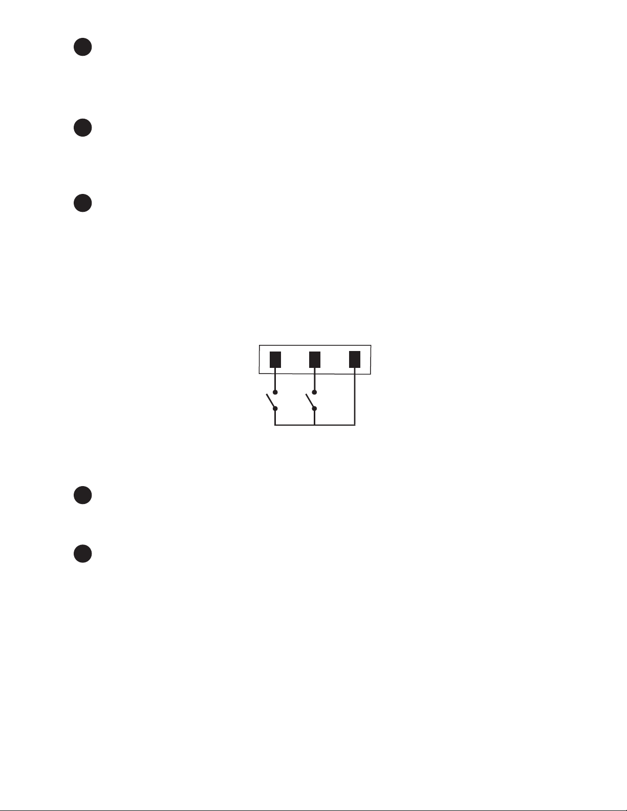
8
Optically isolat ed user inputs
These optically isolated inputs are used to attach an external switch panel for remote control of the
Alpha FXM.
The User Input connector has three contacts (Figure 4) that are used to control the Alpha FXM. The default
settings for the user inputs are as follows:
1 (S1): Shorting this contact to Common starts the Alpha FXM battery test. See "Battery Test" on page 95.
2 (S2): Shorting this contact to Common activates an alarm. See "7.3.4.9 Maintenance > User Input" on
page 63.
3 (SC): Isolated return for contacts S1, and S2.
1 2 3
SC:CommonS1:Self Test S2:Alarm
Figure 4 — User input layout
9
Additional user inputs and dry contacts connector
Enables connection to 3 dry contacts and 2 user inputs on the Micro350 top panel or to optional rack mounting ears (see Figure 20).
10
Status and Alarm LEDs
Status:
Green LED solidly illuminated: the Alpha FXM is in Line mode and line power is provided to the load.
Green LED flashing: the unit is in Inverter mode and backup battery power is provided to the load.
Alarm:
Red LED solidly illuminated: fault in the Alpha FXM. (See "Table P — Fault Submenu" on page 97.)
Red LED flashing indicates an alarm. ( See "Table O — Alarm Submenu" on page 96.)
14
017-241-B0 Rev B
Page 17
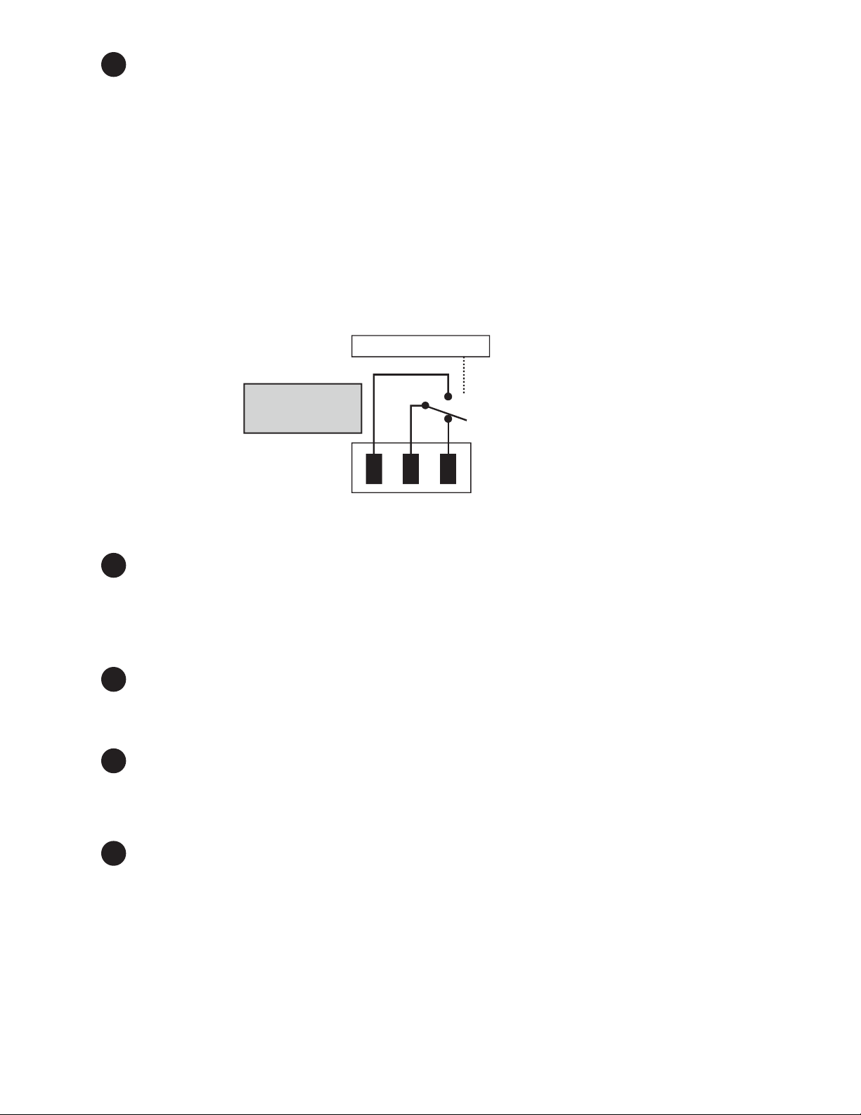
11
Configurabl e dry contacts, C1 and C2
Contacts C1 and C2 allow the Alpha FXM to be connected to an external monitoring panel or to traffic control
equipment.
The factory default settings can be reprogrammed to meet your requirements. See "7.3.3.3 Monitoring > Relay & Load Shed" on page 53 for web and Alpha UPS Monitor, and "7.5.4 Programming the Dry Contacts" on
page 82 for HyperTerminal.
C1: The C1 contact is energized when line power is unqualified and the Alpha FXM provides backup battery
power to the load(s). Can be used to generate an “On Battery” alarm.
C2 : This contact is energized when the battery drops below a pre-set voltage level. Can be used to generate
a “Low Battery” alarm. You can change the pre-programmed level to match the batteries used and the actual
operating conditions. See "Adjusting and Controlling the Alpha FXM" on page 81: #35 Low Battery Warning
Voltage.
Microprocessor
UPS
The contacts have
a maximum rating
of 1A at 250V.
Interior
Normally
Closed (NC)
Replaceable fan assembly
12
Normally
Open (NO)
Common (C)
Figure 5 — Contact Layout (Standard for C1 and C2)
This microprocessor-controlled fan regulates the Alpha FXM internal temperature for optimum performance.
Microprocessor-control of the fan speed increases the life of the internal electronics and the fan.
Take care that the fan is not blocked. Failure of the fan generates an alarm; the internal fan assembly is designed so it can be replaced if it fails.
13
AC input circuit breaker
This circuit breaker is an on/off switch for the line power into the Alpha FXM ,which also provides input protection. It must be switched on for proper Alpha FXM operation.
14
Battery heater mat connector
This connector plugs into a 55W heater mat (optional). The Alpha FXM senses the battery temperature
through the battery temperature sensor (explained in 6 above) and controls the battery heater mat. The
heater mat is set to turn on at 5°C or less and turns off at 15°C.
15
AC input/output conn ections
The terminal blocks provide connections to the AC input and loads for dual outputs.
017-241-B0 Rev B
15
Page 18
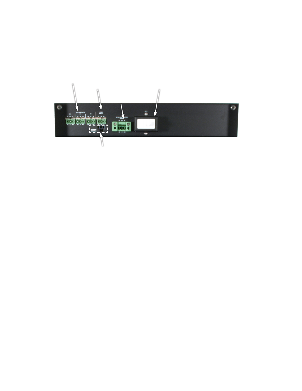
2.4 Micro350 Top Panel
The Micro350 top panel has three additional dry contacts and two user inputs.
The panel also has a door interlock and auxiliary contacts, which can be wired to a user input to generate an
alarm when the door is open.
Dry contacts
C3, C4, and C5
Additional signals connector.
Connects to #9 of gure 3
User inputs
S3 and S4
Door interlock
Open door
switch signal
Figure 6 — Micro350 Top Panel
16
017-241-B0 Rev B
Page 19

3. Site Planning
WARNING!
Restricted Access: The Alpha FXM350 and Micro350 must be installed in a restricted
area accessible only by qualied service personnel.
The Alpha FXM350 and Micro350 are intended for permanent AC connection only.
The Alpha FXM350 and Micro350 must be correctly grounded for proper operation.
Older facilities may have inadequate electrical grounding. Inspection must be performed
by a qualied electrician before installation to ensure that grounding meets the local
electrical code.
The utility line attached to the Alpha FXM input MUST be protected by a circuit breaker
certied for this use in accordance with the local electrical code. The UPS must be connected only to a dedicated branch circuit.
The UPS equipment that is powered by this service panel requires the neutral to be permanently bonded to the ground. Always disconnect the batteries before servicing the
circuit breaker panel.
The input and output lines to and from the Alpha FXM MUST have disconnect devices
attached.
The Alpha FXM is suitable for installations in network telecommunication facilities and locations where the
National Electrical Code applies.
Grounding: The Alpha FXM is suitable both for installation as part of a common bonding network (CBN) and
an isolated bonding network.
For installations above 1400 m (4500 ft) elevation, additional cooling may be needed to reduce the operating temperature of the Alpha FXM. The maximum allowable operating temperature must be reduced by 2°C
(3.5 °F) for every 300 m (1000 ft) above 1400 m (4500 ft).
3.1 Safety Precautions
• Install the Alpha FXM350 and Micro350 and batteries on a surface that can support the total weight. See
Chapter "10. Specifications" on page 98.
• The input wiring must reach a suitably grounded power outlet and the load wiring must reach the
Alpha FXM350 and Micro350 output terminal blocks.
• Place the Alpha FXM350 in a properly sheltered location or inside a weather-proof enclosure to protect
the electronics from water, dust and other possible contamination.
• Backup Generator (If used)
In Generator mode, the Alpha FXM range of acceptable input frequency and voltage is expanded to
accept the fluctuations created by a generator. See "7.2.2 The LCD Control Menu" on page 45, Table B,
Sense Type.
Use a generator with electronic speed and voltage controls which produces less than 10% voltage total
harmonic distortion (THD). Mechanical governors can force the Alpha FXM to run continuously in Battery
mode. Before installation, make sure the generator’s output voltage is compatible with the Alpha FXM
input voltage requirements. To make sure the system runs smoothly, use a generator that supplies twice
as much power as drawn by the total load.
017-241-B0 Rev B
17
Page 20
3.2 Electromagnetic Compatibility (EMC) Requirements
Micro XL Micro XL3
Micro XL3
Observe the following EMC requirements when setting up the Alpha FXM and its internal equipment:
• All AC mains and external supply conductors must be enclosed in a metal conduit or raceway when
specified by local, national, and/or other applicable government codes and regulations.
• The customer facilities must provide suitable surge protection.
• To meet FCC Class B requirements, follow the instructions in section 5.1.4 to attach a ferrite ring to the
connector end of your RJ45 network cable.
3.3 Mounting Options for the Micro350 (XL and XL3)
Figure 7 shows the mounting hardware for the various configurations of the Micro350.
Choose from the following options for mounting the Micro350:
• Mounting to a wooden pole, 5.1.1.1 on page 24.
• Mounting to a steel or concrete pole, 5.1.1.3 on page 26.
• Mounting to a wall, 5.1.1.4 on page 27.
Optional pedestal mounting is shown in Figure 8.
18
Micro Standard
Micro XL3
NOTE: To install a Micro XL3 enclosure, rst attach
the XL to an XL3 kit.
Micro XL
Figure 7 — Mounting the Micro350
017-241-B0 Rev B
Page 21
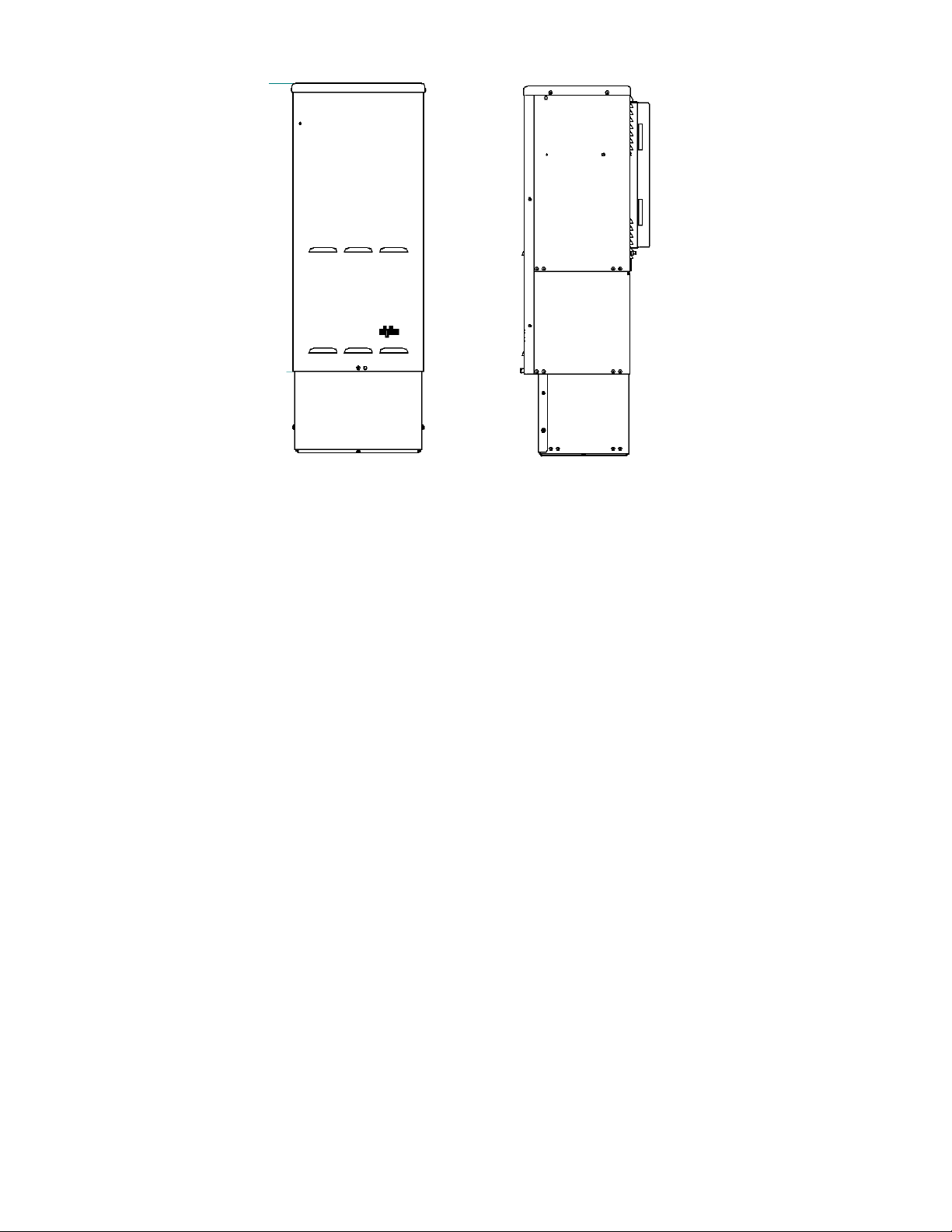
Figure 8 — Mounting on optional pedestal
3.3.1 Battery Heater Mats
The FXM350 and Micro350 allow connection, on its front panel, of a battery heater mat without a thermostat
(#14 in Figure 3). Maximum power of the battery heater mat for use with the FXM350 connector is 55W. The
FXM turns the heater mat on when the temperature measured by the battery temperature sensor senses a
temperature < 5°C. It turns the heater mat off when the temperature raises to >15°C. For the Micro350XL or
bigger systems needing more than one heater mat, it is recommended to use the heater mats with built in
thermostat and daughter heater mats that can be daisy chained. These heater mats may be wired to the AC
in the terminal block on the distribution panel. Ensure that the input breaker is appropriately rated.
017-241-B0 Rev B
19
Page 22
3.3.2 Mounting options for the FXM350
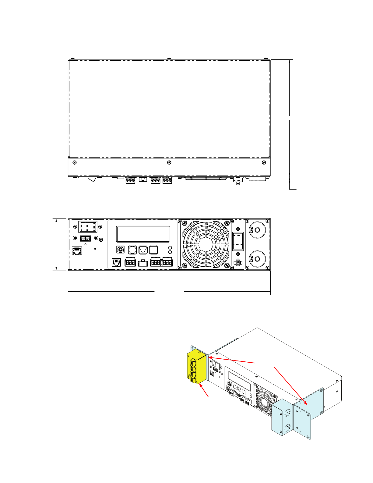
Figure 9 and Figure 11 provide dimensions for mounting the FXM350 UPS as a standalone device.
198
[7.8]
13.7
[0.5]
[3.5]
88
Figure 9 — FXM350 Mounting Dimensions
3.3.2.1 Standalone Configurations:
• Wall mounted, with front access, onto a 19"
mounting tray that includes a battery cabinet
• Rack mounted in a 19" or 23" rack with add-on
ears and a wiring box (Figure 10). An optional
signals assembly can be ordered, which provides two user inputs and three dry contacts.
342
[13.5]
Standard
ears and
wiring box
Optional signals
assembly
20
Figure 10 — Rack-mount options
017-241-B0 Rev B
Page 23
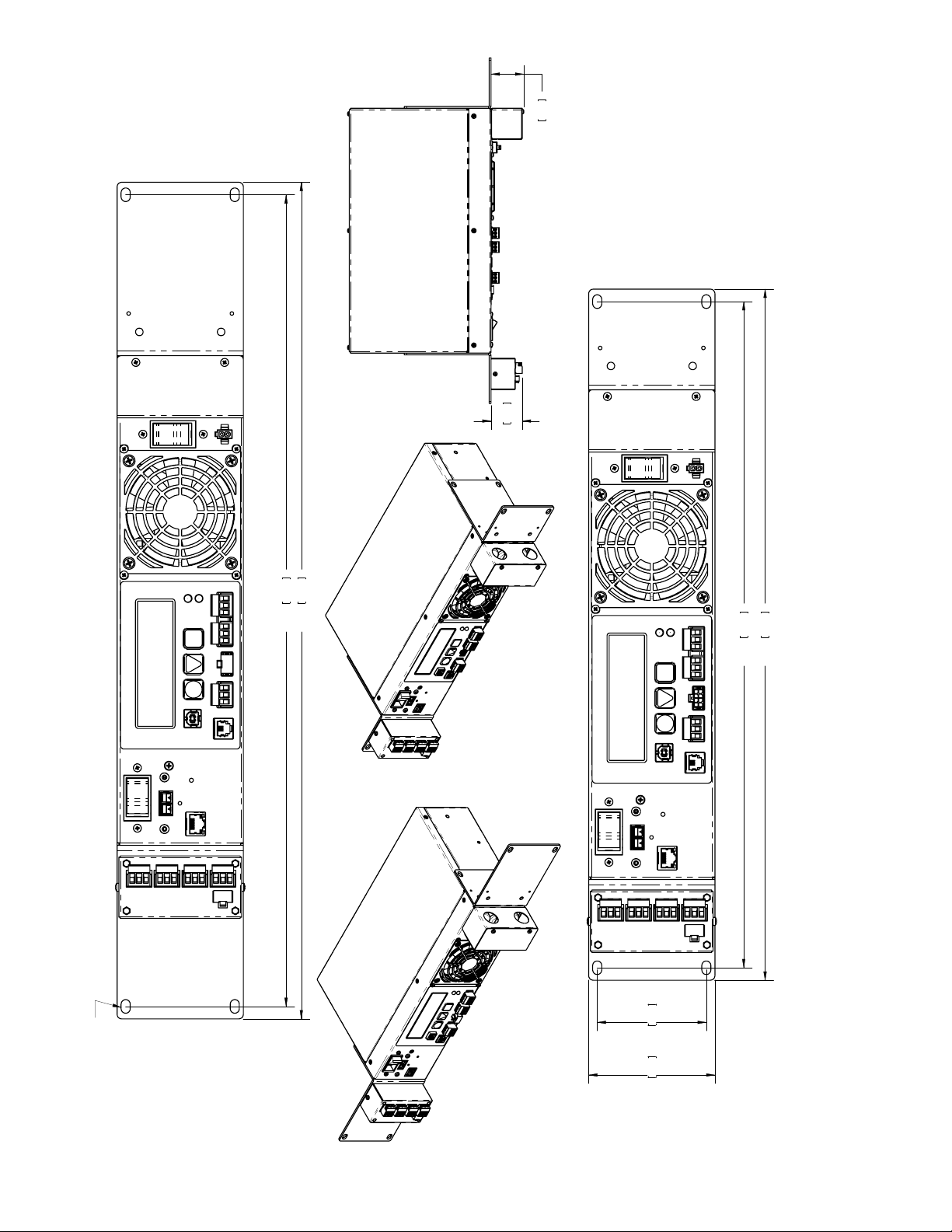
43.7 1.72
46.0 1.81
9.53[0.375]
X
OBROUND THRU
6.35[0.250]
TYP.
566.7 22.31
584.1 23.00
& OPTIONAL EXTERNAL DRY CONTACTS MODULE
FXM 350 w/RACK MOUNT KIT CONFIGURED FOR A 19" RACK
88.1 3.47 76.2 3.00
& OPTIONAL EXTERNAL DRY CONTACTS MODULE
FXM 350 w/RACK MOUNT KIT CONFIGURED FOR A 23" RACK
465.1 18.31
482.5 19.00
Figure 11 — FXM350 with ears for rack mounting
017-241-B0 Rev B
21
Page 24
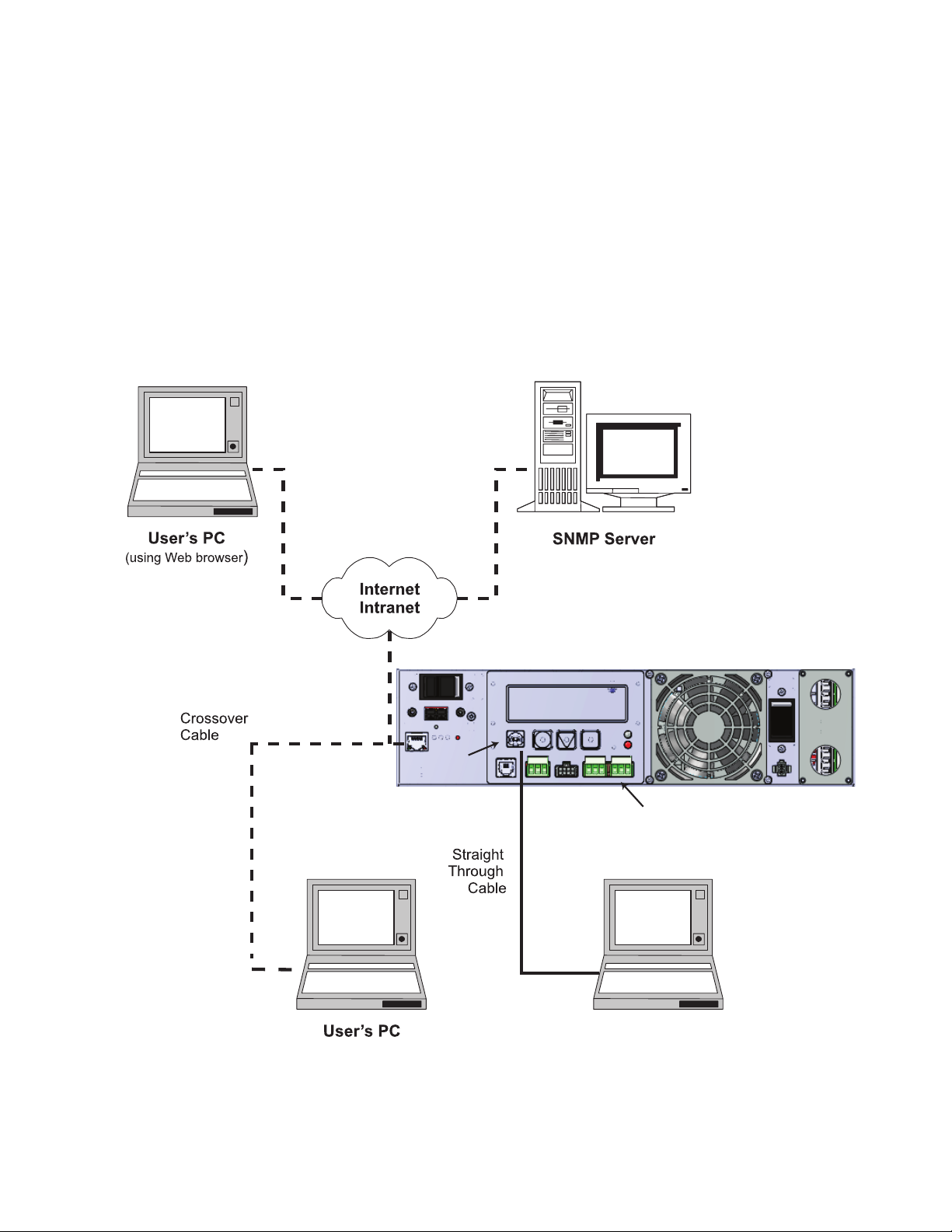
3.4 Options for Communicating with the FXM
There are several ways to communicate with the Alpha FXM UPS:
1. The control panel page 42).
2. Window®’s HyperTerminal or other terminal emulation program to access the UPS command line system
over the USB interface (page 76).
3. Alpha UPS Monitor installed on your computer and connected to the FXM over the USB interface . The
Alpha UPS Monitor software can be downloaded from www.alpha.ca./downloads/.
4. Factory-installed FXM communication module to communicate with the Alpha FXM using any of the
following:
• On site PC
• Company intranet or the internet using a web browser (page 49).
• SNMP communications
Option 4
Option 5
On-Site
Ethernet Connection
Ethernet
Port
USB Port
Option 4
(Use a Web browser for
Ethernet connection
to on-site computer)
FXM350 UPS
Option 1:
Control Panel
Options
2 and 3
User’s PC
(Use Alpha UPS Monitor
or HyperTerminal)
22
Figure 12 — Alpha FXM Communication Options
017-241-B0 Rev B
Page 25

4. Unpacking the Equipment
4.1 Alpha FXM350/Micro350 Configuration
The Alpha FXM is factory installed inside the Micro350 prior to shipping.
WARNING!
The Alpha FXM350/Micro350 combination is heavy, up to 12 kg (26 lb). Use proper lifting
techniques.
4.2 Unpacking
1. Select a suitable area for unpacking.
2. Store all the packing material and boxes for possible equipment returns.
4.2.1 FXM350 Standalone or Micro350 (XL)
1. Check the contents in your product package. The following standard items are shipped together in a
plastic bag:
• Terminal blocks and labels for the dry contacts
• Temperature sensor cable
• Battery clip with screws
• AC plate with screws and bushing
• Ferrite ring
• Cable tie
• Operator’s manual
• USB cable
2. Compare the packing slip and the list of parts with the items you received. If the list of parts on your
packing slip does not match the items you received, or any items appear damaged, immediately notify
your carrier agent and the supplier who prepared your shipment.
4.3 Optional Items
Optional items may include:
• Battery heating mats
• Battery cable kit
• Rack mount ears and wiring box kit for mounting in a 19" or 23" rack (Figure 10)
• Optional signals assembly for FXM350 (Figure 20)
• Distribution panel
Batteries, if ordered from Alpha, will ship separately.
017-241-B0 Rev B
23
Page 26

5. Installation
WARNING!
To avoid personal injury or damage to the equipment, always use at least two installation personnel to remove the unit from its container.
5.1 Installation of the Micro350
WARNING!
Batteries or other components (with the exception of factory-installed components)
must not be installed until the Micro350 cabinet has been securely set in place at its permanent location. Transporting the unit with batteries installed may cause a short circuit,
re, explosion, and/or damage to the battery pack, enclosure and installed equipment.
Damage caused by improper shipping or transporting a unit with batteries installed is
not covered by the warranty.
5.1.1 M ounting the Micro350 Enclosure
5.1.1.1 Mounting to a wooden pole
Have the following tools and materials on hand:
• 13 mm nut driver for the bolts that attach the cabinet to the mounting bracket.
• Two 5/8 inch diameter machine bolts (UNC tread); SAE (Grade 5 or better), length to suit the pole (not
provided).
• Two 5/8 inch diameter zinc-plated flat washers.
• Two 5/8 inch diameter hex nuts (UNC thread).
• Auger or drill for boring 3/4 inch diameter holes in the wood pole.
24
017-241-B0 Rev B
Page 27
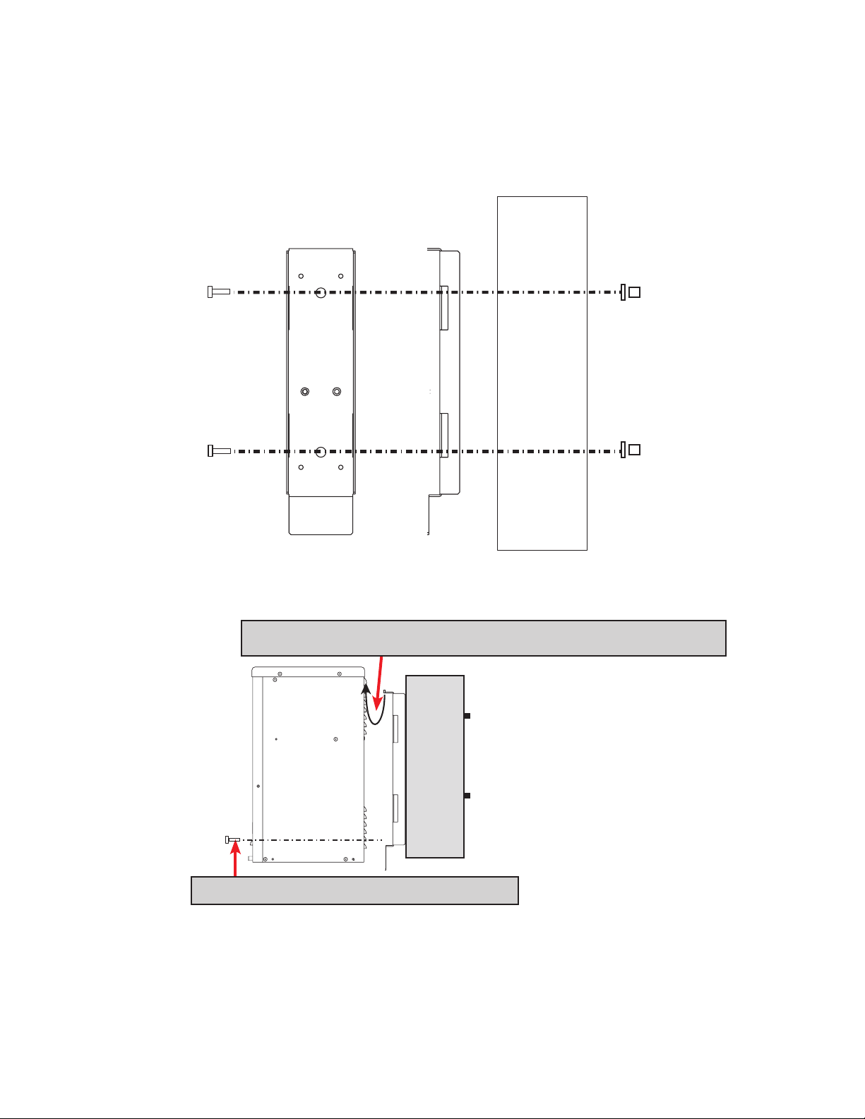
5.1.1.2 Procedure:
1. Using the mounting bracket as a template, drill 2 holes into the pole to accept the machine bolts.
2. Secure the mounting bracket to the pole with the machine bolts as shown in Figure 13.
3. Secure the Micro350 cabinet to the mounting bracket with the supplied bolts (Figure 14).
Front Side Wood
Pole
Figure 13 — Mounting to a wooden pole
a. Hook the top of the mounting bracket under the case’s attachment tting.
b. Secure the cabinet to the mounting bracket.
Figure 14 — Securing the enclosure to the mounting bracket
017-241-B0 Rev B
25
Page 28
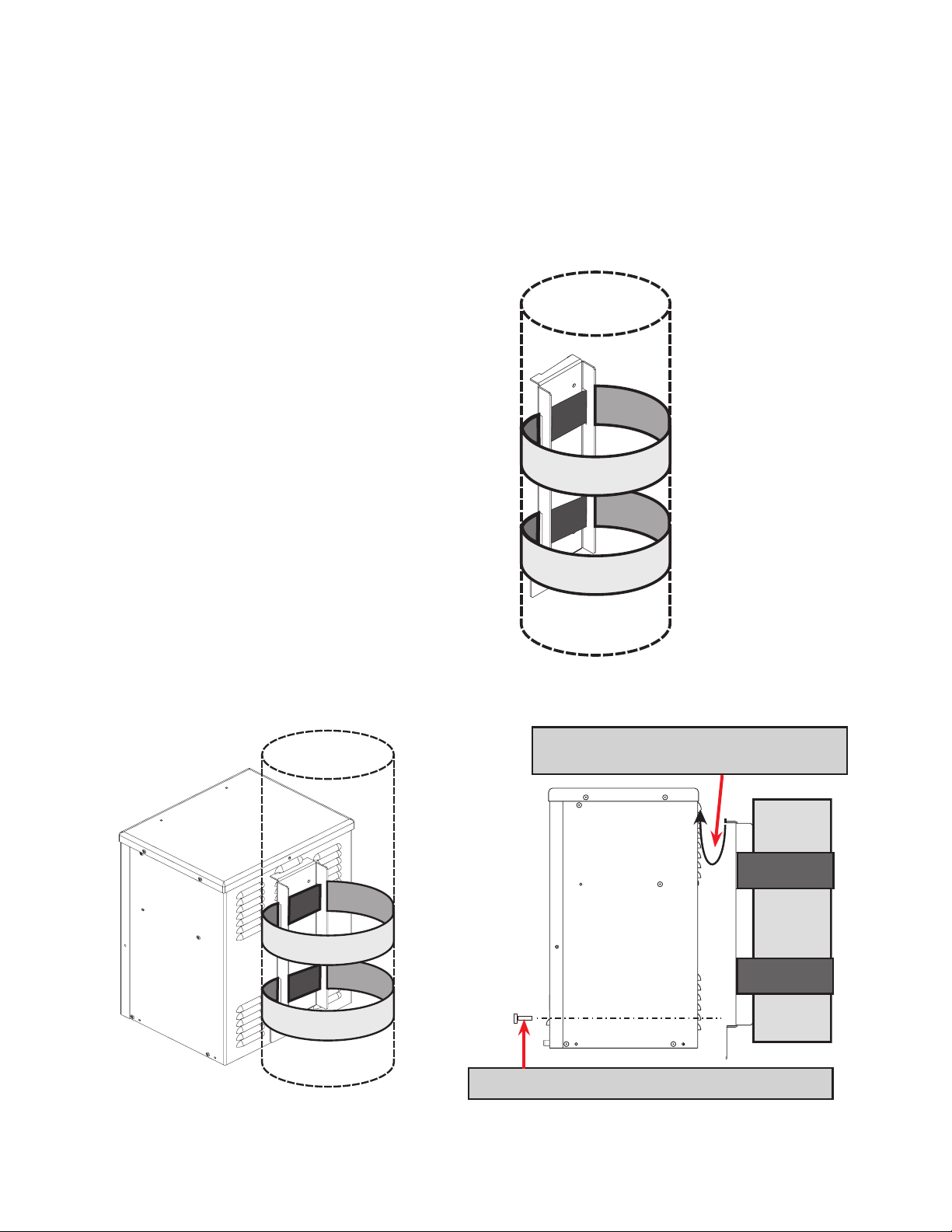
5.1.1.3 Mounting to a Steel or Concrete Pole
Have the following tools and materials on hand:
• 13 mm nut driver for the bolts that attach the cabinet to the mounting bracket.
• Two pole mount straps that fit the pole. Straps must be stainless or galvanized.
• C001 Band-It tool or equivalent.
• C206 3/4 inch stainless steel Band-It band or equivalent.
• C256 3/4 inch stainless steel Band-It buckles or equivalent.
Procedure:
1. Secure the mounting bracket to the pole with
the straps.
Steel or Concrete
Pole
2. Secure the Micro350 cabinet to the mounting bracket with the supplied bolts.
26
a. Hook the top of the mounting bracket under
the case’s attachment tting.
b. Secure the cabinet to the mounting bracket.
017-241-B0 Rev B
Page 29
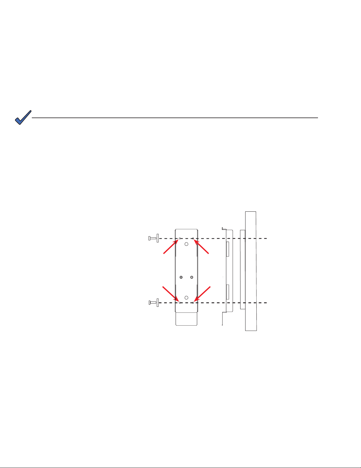
5.1.1.4 Mounting to a Wall
Have the following tools and materials on hand:
• 13 mm nut driver for the bolts that attach the cabinet to the mounting bracket.
• Four 1/4" x 1-1/8" lag bolts.
• Four 1/4" diameter flat washers.
• Drill with 1/8" bit for drilling pilot holes.
• Assorted sockets and wrenches.
Procedure:
NOTE:
If the wall structure is not strong enough to support the weight of the Micro350 enclosure and batteries, use a wooden backing plate that has a minimum thickness of 1-1/4"
and a maximum width of 4" that is securely mounted to a wall stud or studs.
1. Using the mounting bracket as a template, drill 4 pilot holes (indicated by the arrows in the following
diagram) into the wall to accept 1/4" bolts.
2. Secure the mounting bracket to the wall with the 4 bolts and washers.
3. Secure the Micro350 enclosure to the mounting bracket with the supplied bolts.
NOTE:
To install a Micro XL3 enclosure,
rst attach the XL to an XL3 kit.
Figure 15 — Attaching the mounting bracket to the wall studs
Front Side
Wall or
studs
017-241-B0 Rev B
27
Page 30
5.1.2 Wiring the Micro350
OUTPUT
PUSH BUTTON TO
INSERT/REMOVE WIRES
INPUT
PUSH BUTTON TO
INSERT/REMOVE WIRES
L
N
STRIP WIRE
7/16 in
(11mm)
USE
MAXIMUM
12 AWG
2
(4mm )
L
24V
N
WARNING!
Before starting, disconnect the Line power.
If stranded wires are used for connection at the input terminal block, ferrules or equivalent crimping terminals must be used.
Separate the AC input power cables from the output power cables within the Alpha FXM
enclosure. Route them through separate conduit openings in the enclosure.
Separate the DC Battery cable from the AC Input and Output power cables. Route the
cable through its own opening.
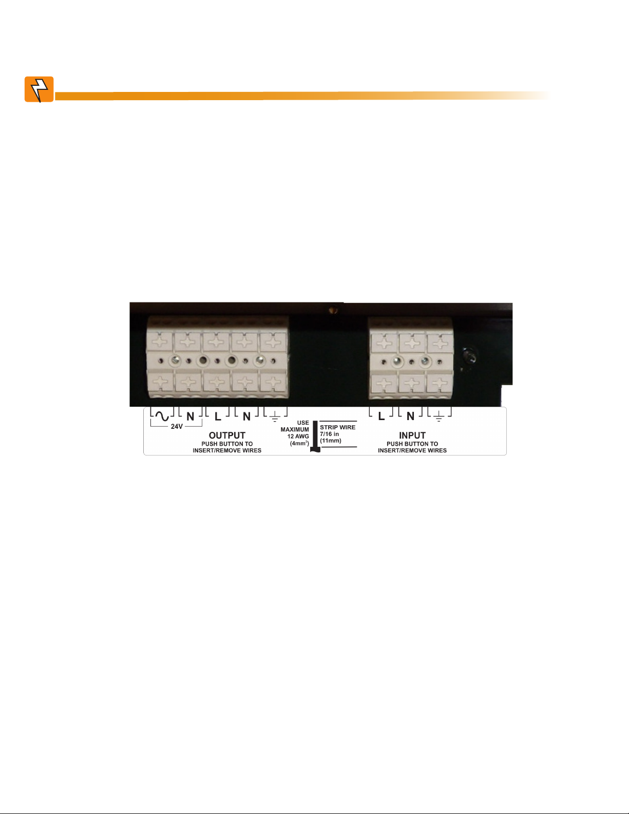
The AC power distribution terminal blocks in the Micro350 enclosure are located in the below the FXM350
(see Figure 16). Refer to Table S for detailed electrical specifications.
Figure 16 — AC Power distribution terminal blocks
Have the following tools and materials on hand:
• Hammer for removing the knockouts
• Slot head screwdriver, 3/16 or smaller, to attach wires to the terminal blocks for the dry contacts / user
inputs on the front panel
• Slot head screwdriver, 1/4 or larger, for removing the knockouts
• DC voltmeter
• Battery terminal corrosion inhibitor such as NOCO Company’s NCP-2 or Sanchem Inc. No-Ox ID Grease
“A”
• Maximum of 12 AWG wire for wiring the input and output terminal blocks
• If used, 1/2" conduit connectors to fit the knockouts (7/8" diameter) and armored conduit to fit
• Optional battery heater mats
28
017-241-B0 Rev B
Page 31

5.1.2.1 Procedure
1. Remove the front cover of the enclosure – lift
the cover up and then pull out at the bottom.
2. If necessary, remove the knockouts with a
hammer and screwdriver.
3. If used, install conduits into the openings.
4. Install the wires into the cabinet. Make sure
that the wiring is long enough to reach the
terminal blocks.
5. Strip the ends of the wires by 7/16" (11 mm).
6. Run the ground wire to the ground terminal
shown in Figure 17.
7. Push in the button on the terminal block and
then insert each wire into the corresponding
terminal. See Figure 18.
8. Secure the wiring to the wiring management
panel with tie-wraps provided with the
Micro350.
9. Remove the packaging around the door
switch after completing the wiring.
Factory installed
ground wire.
Connect ground
wire to copper-
ground terminal.
Remove knockouts for wiring.
Figure 17 — Wiring the Micro350
WARNING!
The input and output wiring must NOT touch the cabinet except for the wiring management panel.
The input terminal block has two inputs for each pole (line, neutral and ground). Make
sure you have inserted each wire into the correct position and not accidentally connected the line and neutral to the same pole.
Verify the line wire is attached to the line terminal block, the ground wire is attached to
the ground terminal block and the neutral wire is attached to the neutral terminal block
to prevent accidental shocks or electrocutions.
CORRECT
INCORRECT
017-241-B0 Rev B
Figure 18 — Terminal block wiring
29
Page 32

5.1.3 Options
If applicable, connect the following—see Figure 3 on page 13.
• USB cable
• Dry contact alarms
• User inputs
5.1.4 Ferrite Ring for Network Cable
Remove the ferrite ring and cable tie from the plastic bag of small parts that were part of your shipment.
Attach the ferrite ring to the connector end of your RJ45 network cable as shown in Figure 19.
Figure 19 — Ferrite ring installed on RJ45 network cable
5.1.5 Battery Heater Mats
For installation and connection of option battery heater mats, refer to section "5.3 Wiring the External Batteries
and Optional Battery Heater Mats" on page 33.
30
017-241-B0 Rev B
Page 33

5.2 Mounting and Wiring the FXM350 as a standalone device
5.2.1 Mounting
The FXM 350 UPS module, which is approximately 13.5 in wide, can be mounted in several ways:
• Wall mounted, with front access onto a 19" mounting tray that includes a battery cabinet
• 19" or 23" rack mounted (with the addition of the optional ears shown in Figure 20). The signal assembly
option provides additional user inputs and dry contacts.
Optional ears
Optional signal
assembly
Figure 20 — FXM350 with rack-mount ears and signal assembly option (wiring box not shown)
5.2.1.1 Rack Mounting the FXM
STEP 1: Install Ears
1. Install the ears at both ends of the FXM.
2. Mount the FXM in the rack.
STEP 2: Install Wiring Box
1. Remove the AC I/O connections cover.
Keep the screws to attach the wiring box.
2. Thread the wires through the wiring box.
3. Attach the wiring box with the four screws
removed in the first step.
4. Complete the wiring as described in
section 5.2.2.
Optional signal
assembly cable
connection
Wiring box instal-
lation location
5. Screw the cover onto the wiring box.
STEP 3: Install Signal Assembly Option
1. Attach the signal assembly to the left ear.
2. Connect the signals connector cable from
the signal assembly to the FXM Figure 20.
017-241-B0 Rev B
AC I/O connections cover
Wiring box
31
Page 34

5.2.2 Wiring the AC Input and Output
WARNING!
Make sure the line power is off and tagged. Switch off all input and output circuit breakers on the FXM350 before making any electrical connections.
The electrical connectors are located on the right
side of the FXM350.
AC Input – 120/230Vac
(#14 AWG)
Ensure that the
cables are routed
AC Output 2 – 24Vac
(#12 AWG)
through the AC
cover plate and/or
wiring box and suitably strain relieved.
AC Output 1 – 120/230Vac
(#14 AWG)
Figure 21 — FXM350 Electrical Connections
5.2. 3 Ferrite Ring for Network Cable
Remove the ferrite ring and cable tie from the plastic bag of small parts that were part of your shipment.
Attach the ferrite ring to the connector end of your RJ45 network cable as shown.
32
017-241-B0 Rev B
Page 35

5.3 Wiring the External Batteries and Optional Battery Heater Mats
WARNING!
The batteries must be installed by qualied personnel trained in the safe use of highenergy power supplies and their batteries. Refer to the safety section in this manual.
• Use new batteries when installing a new unit. Verify that all batteries are the same type with identical
date codes.
• Use appropriate battery voltage string for 24 and 48V versions of the products.
• If you are making your own battery wiring harness, use at least 10 AWG wires.
• The battery return connection is to be treated as an Isolated DC return (DC-I) as defined in GR-1089CORE.
5.3.1 Procedure
1. Place the battery heat mat(s) on the battery shelves. Refer to the manual that ships with the battery heat
mat to connect it to a power source.
2. For FXM350-48 (48V battery string), number the batteries from 1 to 4 with labels or tape. For FXM350-24
(24V battery string), number the batteries from 1 to 2 as shown in the Figure 22.
3. Coat the battery terminals with the corrosion inhibitor.
To positive terminal
Battery #4 Battery #3 Battery #2 Battery #1
To positive terminal
Optional in-line fuse
Optional in-line fuse
Battery #2 Battery #1
To negative terminal
To negative terminal
017-241-B0 Rev B
Figure 22 — External Battery Wiring (for 48 VDC string (top) and 24 VDC string)
33
Page 36

CAUTION!
Torque the battery terminals according to the manufacturer’s specications as given on
the name plate or data sheet.
4. Place the batteries into the enclosure. Orient them so that connecting cable lengths are minimized.
5. If the optional battery restraining bar is used, install it as shown in Figure 23.
6. Connect the batteries as shown in Figure 22. If used, install the in-line fuse.
7. If the Micro XL or XL3 is used, connect and install the extra shelves of batteries.
8. Connect the black battery cable to the negative terminal of the battery string, and the red battery cable to
the positive terminal of the battery string.
9. When the batteries are wired, measure the voltage at the battery connection terminals. It should read 2127V for a 24V battery string and 42-54 for a 48V battery string.
10. Note the polarity and ensure it is correct.
11. Ensure that the DC breaker if OFF.
12. Connect the battery connectors to the FXM350 and install the battery clip.
CAUTION!
Failure to install the battery clip could result in overheating of the battery connectors
and possible damage to the FXM350.
13. Route the sensor end of the battery temperature cable to the batteries.
14. Attach the battery temperature sensor to the body of the battery, about 2 to 3" (5 to 7.5 cm) from the base
of the battery.
1: Hook
the bar
under the
restraining
screw.
34
2: Secure the bar
to the chassis
Figure 23 — Securing the batteries with the optional restraining bar
017-241-B0 Rev B
Page 37

5.4 Start-Up
1. Switch on the FXM battery circuit breaker. The LCD displays STANDBY.
2. Switch on the AC utility breaker at the main power panel. Switch on the AC Input circuit breaker on the
FXM. If qualified, LINE appears on the LCD.
3. Allow the batteries to charge for approximately 8 hours.
4. The load should be receiving power, If not, perform troubleshooting.
017-241-B0 Rev B
35
Page 38

6. Theory of Operation
6.1 Block Diagram
Figure 24 shows the eight PCBs in the FXM350 and the communication path between them.
HEATER
MAT OUTPUT
COMM
MODULE
USER
INTERFACE
DC INPUT
DC EMI
BOARD
HEATER MAT
RELAY BOARD
MAIN BOARD
MICROCONTROLLER
BOARD
LINE FREQUENCY
TRANSFORMER
132
120
108
N
DRY CONTACTS
120
INV
BOARD
AC INPUT
& OUTPUT
AC EMI
BOARD
DRY CONTACTS & EXTERNAL
LCD DISPLAY
Figure 24 — FXM 350 block diagram
SIGNALS OUTPUTS AND USER &
BATTERY TEMPERATURE INPUTS
6.2 Modes of Operation
The following list of operation modes is explained in the following sections.
• Line mode
• Backup mode
• Standby
• Shutdown
• Fault
36
017-241-B0 Rev B
Page 39

6.2.1 Line Mode
132
AC EMI
Output(s)
Input
Grid relay
120
108
120
INV
Inverter/
Charger
N
Battery
In line mode, the voltage input equals the voltage output. The FXM350 has Automatic Voltage Regulation
(AVR) to maintain the output voltage within the regulation range.
6.2.1.1 Boost Mode
When the input voltage drops, a reduction
in output voltage is prevented by increasing the ratio of primary to secondary
windings in the transformer. The ratio is
increased by using a relay to change the
transformer taps.
Input
Grid relay
132
120
108
120
INV
6.2.1.2 Buck Mode
When the input voltage increases, an
increase in output voltage is prevented by
decreasing the ratio of primary to secondary windings in the transformer. The ratio
is decreased by using a relay to change
the transformer taps.
017-241-B0 Rev B
Input
Grid relay
N
132
120
108
N
120
INV
37
Page 40

6.2.1.3 Battery Charging in Line Mode
The battery charging path is shown in Figure 25.
• Charging current of 4A for 48V battery
• Charging current of 6A for 24V battery
• No de-rating of load on AC outputs
AC EMI
Output(s)
Inverter/
Charger
Battery
Input
Grid relay
132
120
108
N
Figure 25 — Battery charging in line mode
120
INV
6.2.2 Back Up (Inverter) Mode
The FXM350 provides back up power from the batteries if utility power fails. The grid relay opens to prevent
power feedback to the grid.
38
Input
Grid relay
132
120
108
N
Figure 26 — Back up power from batteries
120
INV
AC EMI
Output(s)
Inverter/
Charger
Battery
017-241-B0 Rev B
Page 41

6.2.3 St andby Mode
The FXM350 displays STANDBY when the DC breaker is closed (unit is ON), but no AC is present. When the
AC input circuit breaker is switched on and line power is qualified, the Alpha FXM switches to LINE mode. If
AC is within specifications, the FXM provides automatic voltage regulation (AVR).
6.2.4 Shutdown Mode
The FXM/Micro350 can be shut down by switching off the AC breaker and the DC breaker.
The unit can also be shut down from the front panel LCD or remotely through the USB and SNMP.
If the Shutdown command is applied in Back Up mode, the unit shuts the inverter and opens the grid relay
(Figure 26).
If in Line mode, the grid relay is opened and the inverter disabled.
The FXM350 can be removed from Shutdown mode by manually resetting the AC and DC breakers or from
the LCD or the web pages.
6.2.5 Fault Mode
If a fault occurs on the FXM (red LED solidly illuminated), the unit goes into Shutdown mode until the fault is
cleared and reset. See Table P for a list of faults and to clear the fault, see Figure 28.
017-241-B0 Rev B
39
Page 42

7. Operating the FXM350
7.1 Switching the Alpha FXM On and Off
Under normal operation, the Alpha FXM is always powered ON to supply uninterruptible power to the load.
Switching off the Alpha FXM will disconnect the power supply to the load. If for any reason you need to
switch off the Alpha FXM while maintaining power to your critical load, make sure that you have a plan that
provides an alternate source of power.
7.1.1 Switch Off Procedure
1. Switch off the AC input circuit breaker.
2. Switch off the battery circuit breaker.
The status LED turns off and the LCD panel goes blank. The Alpha FXM is now switched off and no backup
power is supplied to the load.
7.1.2 Switch On Procedure (LINE mode)
Before you put the Alpha FXM back into commission, make sure that the line is qualified and the batteries are
fully charged.
1. Switch on the battery circuit breaker. The LCD displays STANDBY and the fan turns on for about a
minute. If the temperature is below –15ºC, the LCD display may not function. See Chapter 9.
2. Switch on the AC input circuit breaker. The Alpha FXM qualifies the line power. The LCD displays
RETRAN, then shows LINE, or BUCK or BOOST, depending on the line voltage. (See Table A on page
43). The status LED illuminates.
3. If there is no line power, the Alpha FXM remains in STANDBY mode until the line power is qualified. To
provide backup battery power to the load, perform a manual start by using the Inverter command:
From the Control Menu, scroll till the LCD displays Inverter, press Select and select ON. See("Figure
28 — LCD Menu Tree" on page 44).
The Alpha FXM uses auto-frequency detection. When it is first switched on, it senses the line frequency and
adjusts its output frequency to match that of the input. The load should be receiving power, If not, perform
troubleshooting.
7.1.3 Switching the Alpha FXM from Line mode to Inverter mode
You can force the Alpha FXM to operate in the Inverter mode by manually switching off the input circuit breaker when in Line mode. Doing so effectively disconnects any line power to the Alpha FXM simulating a power
outage which triggers the Alpha FXM to switch to the inverter mode of operation.
Procedure:
1. Switch off the input circuit breaker. The LCD shows INVERTER, the status LED starts flashing to show
that the Alpha FXM is running on backup battery power. Confirm that the load is receiving power.
40
017-241-B0 Rev B
Page 43

7.1.4 Switching the Alpha FXM from Standby mode to Inverter mode
When AC is not present and the loads need AC Power, the Alpha FXM can be forced to output AC using
energy from the batteries. To force the inverter on, refer to the CONTROL MENU, shown in Figure 28, and
INVERTER in Table B.
7.1.5 Switching the Alpha FXM from Inverter mode to Line mode
The Alpha FXM remains in the Inverter mode for as long as the input circuit breaker is switched off. Backup
power is provided to the load until the batteries are drained to a preset level which triggers the Alpha FXM
to shutdown automatically. If it is not necessary to operate the Alpha FXM in the Inverter mode, switch the
Alpha FXM back to the Line mode as soon as possible by closing the AC input circuit breaker.
Procedure
1. Switch on the AC input circuit breaker. The Alpha FXM qualifies the line power. The LCD displays
RETRAN, then shows LINE, or BUCK, or BOOST.(See Table A on page 43). The status LED illuminates
steadily.
If the Alpha FXM constantly switches between INVERTER and LINE modes because of frequent disturbances on the line, the Alpha FXM input parameters should be broadened from Normal to Generator. See Table B,
Sense Type. Also see the specifications: “Boost/Buck/ Line Transfer Thresholds”.
In the Generator mode, the range of acceptable input frequency and voltage are expanded to accept fluctuations and disturbances as created by a generator.
017-241-B0 Rev B
41
Page 44

7.2 Operating from the Control Panel Interface
The LCD control panel provides “at a glance” monitoring. This panel, when used along with the CANCEL,
SCROLL and SELECT buttons, allows you to program, make measurements, and troubleshoot the Alpha
FXM350. Figure 27 shows the layout.
The Alpha FXM350 is monitored and controlled with a series of menus and submenus. The Menu Tree is
shown in Figure 28.
Alpha
A
A Alpha FXM model name
Alpha FXM voltage conguration - 120 Vac or 230 Vac
B
Alpha FXM Frequency - 50 Hz or 60 Hz
Sense Type setting - Normal (N) or Generator (G); see "7.2.2 The LCD Control Menu" on page 45, Table B,
Sense Type.
C
Present operating mode - See (Table A). (LINE mode shown in Figure 27)
Control buttons:
D
SELECT - Pressing SELECT moves you down 1 level in the menu tree or accepts a change when
programming. Also scrolls through current alarm/fault list.
SCROLL - Pressing SCROLL moves you through the submenus
CANCEL - Pressing CANCEL moves you up one level in the menu tree.
FXM 350
CANCEL
Figure 27 — LCD Control Panel Logo Screen
SCROLL
D
120/60/N
LINE
SELECT
B
C
42
017-241-B0 Rev B
Page 45

7.2.1 Operating Modes
The Alpha FXM operating mode, (see Table A) automatically changes as a result of changes in the line. Refer
to Chapter 10, Specifications, for Boost/Buck/Line transfer thresholds. The LCD panel automatically updates
to reflect the change.
Table A — UPS Operating Modes
LCD display Description
SHUTDOWN The Alpha FXM inverter is switched off. Line power is disconnected from the load.
LINE The Alpha FXM is switched on. Line power is provided to the load.
BOOST1
BUCK1 The Alpha FXM lowers line voltage without using the batteries. AVR is enabled.
When the input voltage is lower than the nominal voltage, the Alpha FXM raises line voltage
without using the batteries. Automatic voltage regulation (AVR) is enabled.
INVERTER
RETRAN The Alpha FXM is transferring from INVERTER mode to Line mode.
TRAN The Alpha FXM is transferring from the state it is now in into Inverter mode.
STANDBY
BYPASS
The Alpha FXM is providing backup battery power to the load. See INVERTER in Table B
on page 45.
The Alpha FXM is switched on and waiting for the line power to be qualied or the user to
clear some faults.
CAUTION: Do not touch the AC output terminals; they may still be energized.
This mode is manually set from the Control Menu. See Figure 28, “Control Menu, INV
BYPASS”. This locks the unit into line mode and turns off the battery charger so the unit can
work with a manual break-before-make bypass switch. AVR will be disabled.
017-241-B0 Rev B
43
Page 46

Logo Screen
CANCEL
(Figure 27)
SELECT
Starting at the Logo
Screen, press the SELECT
button to go down one level.
Press the SCROLL button to move between the menus.
The SCROLL button moves only in one direction and is looped
within a submenu, so if you scroll past your selection, continue
to press the scroll till you reach it again.
Control Menu
(Table B))
The CONTROL
MENU (Table B) lets
you control, program
and adjust the Alpha
FXM for connection
to traffic intersection
equipment or other
applications. You
can control the:
• INVERTER
• DC CONNECT
• BYPASS
• BATT TEST
• BT TS DOD
• AUTO TEST
• SHUTDOWN
• SHUTDOWN AC
• SHUTDOWN DC
• SENSE TYPE
• FUNC MODE
• VOLTAGE
• FREQUENCY
• QUAL TIME
• BATT COMP
• DATE FRMT
• CLOCK FRMT
• INV RECORD
• CHGR CUR
• RELAY TEMP
• TEMP DISP
• DAYLIGHT
• CONFIGURE IP
SCROLL
Status Menu
(Table C)
CANCEL
SCROLL
SELECT
SCROLL
The SYSTEM STATUS
menu (Table C) lets
you measure various
inputs, outputs and
other values. The
available measurements are:
• VIN
• VOUT
• IOUT AC
• BATT TEMP
• FREQ IN
• OUTPUT PWR
• BATT VOLT
• CHGR CUR
• DATE
• TIME
• INV COUNT
• INV (min)
• SHED TIMER 1, 2
OR 3
• MAC Address
• IP Address
• kWh
• REMAIN TM
• SERIAL NUMBER
• VERSION
Alarm and Fault
Menus (If Active)
(Table O and Table P)
SCROLL
Event Status Menu
Press the SELECT button to enter the submenu. Then press
the SCROLL button to cycle through the submenu items. The
SCROLL button moves only in one direction, so if you overshoot,
you have to go all the way around the submenu again.
The ALARM and
FAULT menus that
display NO ALARMS
and NO FAULTS.
When the front panel
alarm LED is on or
flashing, press SELECT.
One of the malfunctions listed in Table
O and Table P will
appear on the LCD.
Press the SCROLL
button to see if more
than one malfunction
is present.
Fix the malfunction.
Press the SELECT
button to clear the
malfunction from the
screen.
If the malfunction is
fixed, the malfunction
is cleared from the
LCD. If it isn’t fixed, it
will reappear on the
screen.
The EVENT STATUS menu displays
the last Alpha FXM
event on the LCD.
For the event log,
see "7.2.5 Viewing
the 200-event Log"
on page 48.
Press the SELECT
button to access
the menu. Press
the SELECT then
the SCROLL button
to scroll through
the events. To see
what a specific
event was, press
the SELECT button.
Press the SCROLL
button to see what
malfunction triggered the event.
44
Figure 28 — LCD Menu Tree
017-241-B0 Rev B
Page 47

7.2.2 The LCD Control Menu
The control menu (Table B) lets you operate the Alpha FXM or program it to suit your operating conditions.
7.2.2.1 Procedure
1. From the Logo screen press the SELECT button to go down to the CONTROL menu.
2. Press the SELECT button to enter the submenu (Table B).
3. Press the SCROLL button to move between items in the submenu.
4. When you have reached the item you want to change, press the SELECT button. The item chosen will
blink.
5. To toggle between the choices, press the SCROLL button. Stop when you reach the choice you want.
6. To make the change, press the SELECT button. The blinking stops.
Table B — Control Menu
LCD display Meaning Description
When inverter mode is set to ON, the Alpha FXM provides backup battery power
INVERTER Inverter
DC CONNECT
BYPASS
DC Output
Connect
Voltage
Inverter
Bypass
to the load. This mode of operation is normally activated automatically when line
power becomes unavailable, or the line power is not qualied. You can also put
the Alpha FXM into this mode during initial startup in the absence of line power or
because of unqualied line power. See #31Inverter On/Off in Table I.
One of the dry contacts of the FXM350 can be programmed to operate as a
control for external DC disconnect and reconnect. (See LVD setting under "7.5.4
Programming the Dry Contacts" on page 82). The dry contact is energized when the
battery voltage is greater than the DC Connect set voltage and will de-energize if the
battery voltage drops below 42V for 48V system (21V for 24V system). The default
reconnect voltage is set to 48VDC and can be adjusted up to 51VDC.
This function can be enabled only when the Alpha FXM is in Line mode.
When enabled, the FXM locks into Line mode (no AVR) and disables the battery
charger. This mode is used when maintaining batteries.
OR
Allows the use of a break-before-make manual bypass switch so the Alpha FXM can
be shut off for maintenance without interrupting power to the load.
BATT TEST Battery Test
BT TS DOD
AUTO TEST Automatic Test Enable/Disable the scheduled self test.
SHUTDOWN
SHUTDOWN AC Shutdown AC
SHUTDOWN DC Shutdown DC
SENSE TYPE Sense Type
Shutdown AC
and DC
Starts the battery test that uses depth-of-discharge setting that can be adjusted
using BT TS DOD menu.
Lets you set the desired battery test depth-of-discharge to a value between 0 and
100%. Make sure that the set time duration is shorter than the max back up time of
your battery bank. Otherwise, you will drain the battery and trigger a fault – Batt Volt
Low. The default value is set to 20% DoD.
When this function is switched on, the Alpha FXM inverter is shut off. Neither Line
nor Inverter power is supplied to the load. If a dry contact was used as a LVD, the
LVD will open. See section 7.5.4.
When this function is switched on, the Alpha FXM inverter is shut off. Neither Line
nor Inverter power is supplied to the load.
When this function is switched on, the Alpha FXM DC output is shut off. Available
when dry contact C1 is programmed to be the Low Voltage Disconnect indicator.
See "7.5.4 Programming the Dry Contacts" on page 82.
This function can only be used when the Alpha FXM is in Standby or Shutdown
mode—see Table A for operating mode descriptions.
This function toggles between:
NORMAL: The Alpha FXM can operate successfully with most line conditions.
OR:
GENERATOR: The Alpha FXM input voltage and frequency parameters are
expanded so the Alpha FXM can work with the uctuations caused by a generator or
noisy line.
017-241-B0 Rev B
45
Page 48

Table B — Control Menu
LCD display Meaning Description
FUNC MODE Functional
VOLTAGE Voltage
FREQUENCY Frequency
QUAL TIME
BATT COMP
DATE FRMT
CLOCK FRMT
INV RECORD
CHGR CUR
RELAY TEMP
TEMP DISP
DAYLIGHT
CONFIGURE IP IP Lets you congure the UPS IP address
Mode
Line qualify
time
Battery
temperature
compensation
Date Format
Selection
Clock display
format option
Inverter record
clear
Charger
current
Relay
temperature
Temperature
display format
Daylight saving
option
This function toggles between:
AUTOMATIC VOLTAGE REGULATION (AVR): The buck and boost modes are
active.
OR:
QUALITY: The buck and boost modes are switched off, the input voltage is the
Alpha FXM output voltage.
Lets you set the Alpha FXM output voltage setting to 120 Vac or 230 Vac. This
should ONLY be done by a qualied technician acting under the instructions of Alpha
Technologies Customer Service Department. Failure to contact Alpha Technologies
before performing this procedure could void your warranty.
The frequency can only be changed when the Alpha FXM is in Standby mode. This
lets you set the Alpha FXM’s frequency setting to 50 Hz or 60 Hz. This should ONLY
be done by a qualied technician acting under the instructions of Alpha Technologies
Customer Service Department. See "Service and Technical Support". Failure to
contact Alpha Technologies before doing this procedure could void your warranty.
Lets you set how long it takes for the Alpha FXM to return to Line mode after the
line has become requalied to make sure the line is stable. It can be set to 3, 10, 20,
30, 40 or 50 seconds. The factory default setting is 3 seconds. Also See #34: Line
Qualify Time in Table I.
Lets you set the battery temperature compensation to match the batteries you are
using. It can be set to -2.5, -4, -5 or -6 mV/°C/Cell. The factory default setting is -5
mV/°C/Cell.
This lets you toggle the Alpha FXM date format between YY-MM-DD, MM-DD-YY,
YYY-MM-DD, MM-DD-YYYY, DD-MM-YYYY, YY-TXT-DD, TXT-DD-YY, DD-TXT-YY,
YYYY-TXT-DD, TXT-DD-YYYY, DD-TXT-YYYY, YYYY-DD-TXT, YY-DD-TXT, YYYYDD-MM, YY-DD-MM. The factory default setting is MM-DD-YY.
Lets you select which format to display time information: in 24 hour clock format or
12 hour clock (AM/PM) format.
This clears the inverter counter and timer from the LCD system status menu. This
does not clear the 200-event log..
Allows you to set the battery charger current to either 0 A, 1 A, 2 A, 3 A or 4 A for
48V systems and 5A or 6A for 24V systems. NOTE: Setting the battery charger to
0 A will turn the charger off.
Temperature setting to activate the specied dry contact. The congured dry contact
will activate when the set battery temperature is reached. Setting range: 20ºC to
55ºC (68 ºF to 131ºF). The default setting is 55ºC (68 ºF). The relay is de-energized
when the temperature drops by 10ºC (18ºF) .
The temperature can be displayed in Celsius or Fahrenheit.
Switch ON this option to activate Day Light Saving time.
7.2.3 Controlling the external fan by temperature triggered dry contact
The Temperature trigger has a user configurable range of +20°C to +55°C (68 – 131°F). When the battery temperature (monitored by the battery temperature probe) reaches the high temperature threshold, the
assigned relay energizes and can be used to turn on the external fan. The relay is de-energized when the
temperature drops by 10ºC (18ºF). The default high temperature threshold is 55ºC (63ºF).
7.2.3.1 Procedure
From the Logo screen, navigate to Control Menu > RELAY TEMP. Press the SELECT button and the current
temperature display will start flashing. Use the Scroll button to change the temperature in 5°C (9ºF) increments. Press SELECT to accept the changes or CANCEL to abort.
RELAY TEMP
55
120/60/N
LINE
46
017-241-B0 Rev B
Page 49

7.2.4 Making Measurements
The System Status menu lets you make measurements of various Alpha FXM inputs, outputs, temperatures
and other values.
7.2.4.1 Procedure
1. From the Logo screen go to the SYSTEM STATUS menu.
2. Press the SELECT button to enter the submenu (Table C).
3. Press the SCROLL button to move between items in the submenu. When you reach the item you want
to measure, stop pressing the button. The measurement is automatically displayed on the LCD. It is
automatically updated every 0.5 seconds.
Table C — System Status Menu
LCD display Meaning Description
VIN Input Voltage The line input voltage into the Alpha FXM
VOUT Output Voltage
IOUT AC
BATT TEMP
FREQ IN Input Frequency The frequency of line power into the Alpha FXM (Hz).
OUTPUT PWR Output Power The Alpha FXM output power in VA (true RMS).
BATT VOLT Battery Voltage The battery output voltage (VDC).
CHGR CUR Charger Current The Alpha FXM battery charging current is set to this value (Amps).
DATE Displayed in the format set by the user.
TIME
INV COUNT # of line failures
INV (min)
SHED TIMER1
SHED TIMER2
SHED TIMER3
MAC Address
IP Address
kWh kWh Meter The accumulated output energy is displayed.
Remain Tm
Serial Number
VERSION Software Version The software version used in this Alpha FXM
Output Current
(AC)
Battery
Temperature
Amount of time
inverter was on
Amount of
time until the
dry contact is
activated.
Communication
Module's MAC
Communication
Module's IP
Remaining
Battery Runtime
Unit Serial
Number
The Alpha FXM output voltage (true RMS).
The Alpha FXM AC output current (true RMS).
The battery’s temperature (°C).
Displayed in the format set by the user.
Shows how many times the inverter has been active since the last time the
inverter counter was cleared. See INV RECORD description in Table B.
shows total time in minutes the inverter has been active since the last time
inverter timer was cleared. See INV RECORD description in Table B
The factory default dry contact for this setting is contact C4. SHED TIMER2 and
SHED TIMER3 can be eld programmed. See “Setting the Timer Contact”. This
display shows the amount of time left in seconds until the contact is activated.
The factory default setting is 2 hours, but this can be changed as shown in
"Programming the Dry Contacts and the Clock". C4 is available on the FXM350 if
the optional signal assembly is installed—see Section 3.3.2.
The Communication Module's MAC address is displayed.
The Communication Module's IP is displayed.
The remaining runtime of the battery is displayed. Refer to Appendix A to set
battery parameters.
The unit serial number of the Alpha FXM is displayed.
017-241-B0 Rev B
47
Page 50

7.2.5 Viewing the 200-event Log
Using the LCD display, or web interface, you can view up to the last 200 events the Alpha FXM went through
and the malfunctions that triggered each of them. If more than 200 events occurred, the oldest is overwritten.
To clear this log, see “Operating the Alpha FXM, INV RECORD.”
To view the events on the LCD display, refer to the following procedure.
7.2.5.1 Procedure
1. From the Logo screen, navigate to the EVENT STATUS MENU.
EVENT STAT
MENUS
2. Press the SELECT button to enter the submenu.
3. The following log screen appears.
DATE EVENT HAPPENED
(YY:MM:DD) (Depends on
selected date format)
OPERATING MODE THE Alpha FXM350 and Micro350
WAS IN WHEN THE EVENT HAPPENED (Line shown)
06:11:29
16:23:56
TIME EVENT HAPPENED
(HH:MM:SS 24-hour clock)
(Depends on selected date format)
4. Press the SELECT button. The event counter flashes.
5. Press the SCROLL button to scroll through the event counter.
6. When you reach the event you want press the SELECT button.
7. The event loading screen appears and then the log screen reappears with the details for that event.
120/60/N
LINE
LINE
EVENT: 1
EVENT COUNTER
(Event #1 shown)
48
Event
Loading
ALARM STATUS
EVENT: 1
Over Load
8. Press the SCROLL button. One of the faults or alarms, shown in Table O and Table P, is displayed and is
the malfunction that triggered the event.
017-241-B0 Rev B
Page 51

7.3 Operating via the FXM Communication Module (Intranet or Internet)
The internet or a company intranet can be used to communicate with the Alpha FXM through the factoryinstalled FXM communication module. In addition, the Alpha FXM can be monitored and controlled via a web
browser or with SNMP protocols.
B
A
A Screen selection menus
B Current UPS operating mode. Updates automatically.
Fault and alarm indicators – when a light in this bar is illuminated, move the mouse
C
cursor over the light to determine the malfunction. Double-clicking on the light will
send you to the Alarms & Faults screen.
D Readout screens
C
D
017-241-B0 Rev B
Figure 29 — Web GUI (UPS Specification Screen shown)
49
Page 52

7.3.1 Installation and Set Up
The following tools and materials are needed:
• Computer with network card and web browser
• Cross over cable or hub
• The UPS Final IP Address and Subnet Mask and if needed the Default Gateway and the DNS Server addresses
CAUTION!
To successfully complete this procedure, you should have a working knowledge of
network protocols and how to congure them. Consult your network administrator for
details.
If multiple UPS are installed on the same network, congure each unit’s IP address
before the installation. (See "Figure 27 — LCD Control Panel Logo Screen" on page 42.)
Each UPS on the network MUST have its own unique IP address.
7.3.1.1 Procedure
1. Connect the Alpha FXM to a personal computer with either the cross over cable or a hub.
2. Open the web browser on the computer.
3. Configure the network card to talk to the FXM communication module. The module’s default address is
http://192.168.0.90.
4. Cut and paste the IP address into the browser and press ENTER.
5. Select Com m unications > Configure TCP/IP in the home screen (Figure 29).
6. Configure the TCP/IP properties according to your network’s requirements.
7. Click Apply Settings.
50
Figure 30 — Alpha UPS Monitor: UPS Communications screen
017-241-B0 Rev B
Page 53

7.3.2 UPS Specifications
This screen displays the Alpha FXM350 specifications.
Figure 31 — Web GUI: UPS Specification screen
017-241-B0 Rev B
51
Page 54

7.3.3 UPS Monitoring
These read-only screens show the Alpha FXM current input and output values and other measurements.
7.3.3.1 UPS Monitoring > Input & Output
Shows the current line input and Alpha FXM output values and the Alpha FXM present operating mode.
NOTE:
Voltage 2 and Current 2 are the output voltage and current of the 24 VAC output.
Figure 32 — Web GUI: Input & Output screen
7.3.3.2 UPS Monitoring > Battery & Inverter
Shows the battery string status and how many times and for how long the inverter has been active.
52
Figure 33 — Web GUI: Battery & Inverter screen
017-241-B0 Rev B
Page 55

7.3.3.3 Monitoring > Relay & Load Shed
Shows how the front panel dry contacts are configured. If any relays are used for load shedding, the time setting is shown.
Available with
optional additional
dry contacts.
C6 is not available with this
model.
Figure 34 — Web GUI: Relay & Load Shed screen
7.3.3.4 Monitoring > User Input Status
Shows the current status of the user programmable inputs 1 to 4.
Figure 35 — Web GUI: User Input Status screen
017-241-B0 Rev B
53
Page 56

7.3.4 UPS Maintenance Menus
Use the UPS Maintenance screens to configure and adjust the Alpha FXM to meet your operating needs.
To change parameters, either click the On/Off buttons or select an item from a drop down menu.
To execute the changes, click on the Update Configuration button.
7.3.4.1 UPS Maintenance > Unit Configuration
7.3.4.2 Sets the name, input, output and how often the Alpha FXM parameters update.
Figure 36 — UPS Maintenance: Unit Configuration screen
7.3.4.3 Restoring All Parameters to Default Values
The purpose of this command is to reset the Alpha FXM to the factory default parameters in Table D.
CAUTION!
This command resets all parameters that are user-congurable. This command is password protected. All previously programmed operation will be lost.
54
Figure 37 — Restore all default commands
017-241-B0 Rev B
Page 57

Table D — List of Parameters
Maximum battery charging current
Temperature compensation of battery charging
Property settings of programmable user input #1
Action #1 setting of programmable user input #1
Action #2 setting of programmable user input #1
Property settings of programmable user input #2
Action #1 setting of programmable user input #2
Action #2 setting of programmable user input #2
Property settings of programmable user input #3
Action #1 setting of programmable user input #3
Action #2 setting of programmable user input #3
Property settings of programmable user input #4
Action #1 setting of programmable user input #4
Action #2 setting of programmable user input #4
Start hour of rush hour of time of day action period #1
Start minute of rush hour of time of day action period #1
End hour of rush hour of time of day action period #1
End minute of rush hour of time of day action period #1
Start hour of rush hour of time of day action period #2
Start minute of rush hour of time of day action period #2
End hour of rush hour of time of day action period #2
End minute of rush hour of time of day action period #2
Format setting of date display on LCD
Line qualify time
Time setting of periodical self-test (minute) (hh:mm)
Inverter off delay setting
Number of weeks setting of periodical self-test
Day of the week setting of periodical self-test
Time of the day setting of periodical self-test
Battery low warning threshold setting (%)
Self test depth-of-discharge setting (%)
Internal temperature setting to turn on cooling fan
Load shed timer1 duration
Load shed timer2 duration
Load shed timer3 duration
Programmable dry contact #1 setting
Programmable dry contact #2 setting
Programmable dry contact #3 setting*
Programmable dry contact #4 setting*
Programmable dry contact #5 setting*
Password setting
*Available with additional optional dry contacts
017-241-B0 Rev B
55
Page 58

7.3.4.4 UPS M aintenance > Battery: Allows adjustments of battery string voltage, charging
parameters, low battery warning setting, periodic self test time, and starts the self test.
Figure 38 — UPS Maintenance: Battery screen
An accurate battery runtime estimation requires adjustment of the following parameter:
• Peukert Number: Refer to Appendix A for calculation of the Peukert number to enter here.
• Battery Capacity: This is the rated capacity (Ah) of the battery shown on the battery data sheet. Do not
confuse the battery capacity with the Peukert capacity.
• Battery Open Circuit Voltage: This number is obtained from the battery data sheet. The battery data
sheet shows the value for a single battery, so for a 48 V system where 4 batteries are connected in series, this number must be multiplied by four.
The Battery Runtime Remaining algorithm attempts to calculate the health of the battery to get a more accurate prediction of the remaining battery runtime. An accurate estimate of the battery health requires that at
least one battery discharge cycle greater than 20% depth of discharge has taken place since the unit was
switched on. When the unit is powered up from an off state, the algorithm assumes that a new battery is connected to the unit. Each discharge of greater than 20% will result in a new calculation for the relative battery
health. This value is then used in the Battery Runtime Prediction algorithm to compensate for an aging battery. We recommend that the user set up a periodic (every 6 months) battery test with a depth of discharge of
at least 20%.
The Battery Runtime Remaining algorithm relies heavily on the battery voltage to predict the remaining runtime. This results in a less accurate predicted runtime during periods when the battery voltage is changing
rapidly. The battery voltage typically changes rapidly during the first few minutes of discharge when the unit
switches from charging to discharging while the unit is in the Inverter mode. The battery voltage may also
change rapidly during the last 20% of the discharge time when the battery is almost drained.
CAUTION!
The battery runtime is only an estimation and must not be relied on for critical applications. The battery runtime remaining is applicable only in inverter/backup mode.
56
017-241-B0 Rev B
Page 59

7.3.4.5 UPS Maintenance > Inverter: Turns the inverter on or off to start or stop backup battery
power to the load.
Figure 39 — UPS Maintenance: Inverter screen
017-241-B0 Rev B
57
Page 60

7.3.4.6 UPS Maintenance > Relay & Load Shed: The Alpha FXM has 2 dry contacts (C1 and C2) on
the front panel which can be configured by the user to open or close based on the specific trigger conditions. C3
to C5 are available with optional additional dry contacts. See Table J for a description of all available dry contact
functions.
See Table J for a
description of all
available dry contact functions.
C3 to C5
are available
with optional
additional dry
contacts.
C6 is not
available with
this model
58
Figure 40 — UPS Maintenance: Relay & Load Shed screen
017-241-B0 Rev B
Page 61

Programmable Dry Contact Time of Day Action
Inverter
mode
entered
Dry contact
activates when timer
counts down to zero
Timer
starts to
count down
Microprocessor
Inverter
mode
entered
Dry contact activates
when enabled timer
counts down to zero
Timer starts to
count down
if enabled
Microprocessor
Real time clock
Peak period
settings
Disable Timer (Action=ON) or
Enable Timer (Action=OFF)
You can assign a dedicated timer to a dry contact. Upon entering the Inverter operating mode, the timer
is activated and begins to count down from a user defined value. When the timer reaches zero, the programmed dry contact relay is activated (Status = ON).
Figure 41 — Programmable Timer Operation
An example of a typical application of this timer-controlled dry contact function is control of a traffic light.
When the grid power fails, the Alpha FXM goes into the Inverter mode and continues supplying backup power to the traffic light. Since the batteries supplying the backup power have limited capacity, a timer controlled
dry contact is usually configured to switch the traffic light into the flashing amber or flashing red mode after a
user-defined period to conserve battery power.
This setup works for non-rush hour traffic, but during rush hour, it may be desirable to keep the traffic light
running normally as long as backup power is available. To address this issue, a new feature called the Time
of Day Action has been added to deactivate the timer during a user defined time period up to twice each
day.
017-241-B0 Rev B
Figure 42 — Time Of Day Action Operation
59
Page 62

You can define up to 2 peak time periods of the day in the Maintenance > Relay & Load Shed screen:
1. In the Time of Day Action Configuration dialogue box, set up the start and end time of the first rush hour
under Time Period 1 and the second rush hour under Time Period 2. In this example, during the first time
period (7 AM to 9 AM), all 3 timers are disabled (they do not count down at all). Similarly, all timers are
disabled during the second time period (3 PM to 6 PM).
2. Select ON under each time period. Click the Update Configuration button under the time periods to store
the settings.
Figure 43 — Time Of Day Configuration
3. Confirm your settings in the UPS Monitoring > Relay & Load Shed > Time of Day Action Status screen.
Once the Time of Day Action is configured, the Alpha FXM will automatically disable the timers during the
Inverter mode at the defined peak periods.
You can switch off the Time of Day Action by setting one or both time period(s) to OFF (Figure 44). The dry
contact will be activated by the timer regardless of the peak period settings.
60
Figure 44 — Time Of Day Action Status
017-241-B0 Rev B
Page 63

Controlling the external fan with a temperature trigg ered dry contact
The Temperature trigger has a user configurable range of +20°C to +55°C (68 – 131°F). When the battery
temperature (monitored by the Battery Temperature Probe) reaches the threshold, the assigned relay energizes. The relay de-energizes when the temperature drops 10°C (18°F) from the Set temperature.
This relay can be used to turn on the external fan. Figure 45 shows the Relay Configuration window under the
UPS Maintenance > Relay & Load Shed screen. As an example, to assign C1 as the Temperature trigger,
a. Select Temperature from the drop down menu.
b. Click Update Configuration and the current status updates momentarily.
c. Figure 46 shows the fan-on temperature threshold set at 55°C. To change this value, type the
new value in the Fan On Temperature box (or use the up/down arrow keys) and click Update
Configuration to update the current status display.
See Table J for
a description of
all available dry
contact functions
Figure 45 — Assigning the Temperature trigger function to a dry contact – Alpha UPS Monitor
Figure 46 — Setting the Temperature trigger value
NOTE:
C1 can also be used to trigger a High Temperature alarm.
017-241-B0 Rev B
61
Page 64

7.3.4.8 UPS Maintenance > Time & Date: used to set the Alpha FXM date and time.
Figure 47 — UPS Maintenance: Time & Date screen
7.3.4.7 UPS Maintenance > Password: used to reset the Alpha FXM password, which is limited to 4
alphanumeric characters. The factory set password is 1111.
62
Figure 48 — UPS Maintenance: Password screen
017-241-B0 Rev B
Page 65

7.3.4.9 Maintenance > User Input
Two programmable user inputs are available as well as two optional user inputs. They can be user-configured
similar to the dry contact relays. Supported functions include: (a) Shutdown, (b) User Alarm and (c) Self Test.
Any user input can be configured to perform a certain action in response to different trigger types and logic
levels. For example, if you want the Alpha FXM to issue an intrusion alarm when the door is opened, you
need to wire the door with a switch that triggers a user input every time the door is opened. The following
procedure describes how User Input 1 can be configured as an intrusion alarm input.
Procedure
1. Select UPS Maintenance > User Input to display the User Input Configuration window.
2. In the Input 1 column, select the Type down arrow to display the 3 types of available triggers: Edge
Trigger, Level Toggle, and Level Alternative. For more information on how triggers work, see "Appendix B
- Types of Triggers" on page 106.
Figure 49 — User Input Configuration: Setting the Trigger Type
3. Select Edg e Trigger.
4. Select Low from the Level drop down menu. The User Input goes to logic level "low" whenever it is
triggered.
NOTE:
Note: Even though the system is designed for edge trigger the minimum width of the
pulse must be 200 mS
017-241-B0 Rev B
Figure 50 — User Input Configuration: Setting the Logic Level
63
Page 66

5. Select User Alarm On from the Action #1 drop down menu.
Figure 51 — User Input Configuration: Setting an Action
6. Click the Update Configuration button and enter the password to confirm if required.
7. Check the User Inpu t Current Status at the UPS M onitoring > User Input St atus page.
Figure 52 — User Input Current Status
Perform a quick test by shorting the User Input 1 to SC (ground) with a short length of PVC insulated electronic wire. The Alpha FXM should issue a User Input Alarm .
Figure 53 — User Input Current Status
Hovering the cursor over the amber indicator displays the corresponding context sensitive message.
64
017-241-B0 Rev B
Page 67

7.3.5 Event Manager
7.3.5.1 Alarms & Faults
This read-only screen shows the operating status of the Alpha FXM. When the fault or alarm indicators on the
horizontal bar are illuminated, place the mouse cursor over the light to display the context sensitive message.
Figure 54 — Alarms & Faults screen
7.3.4.10 Event History
This screen shows the last 200 events recorded by the Alpha FXM. Choosing a number in the Event Index
drop-down box and then clicking on the View Selected button displays the updated information about the
selected event.
017-241-B0 Rev B
Figure 55 — Event History screen
65
Page 68

To view all the events, click All Events to open the Event Log Monitor window. Clicking on the Clear His-
tory button clears the log. This action cannot be undone.
66
Figure 56 — Event Log Monitor screen
In the Event Log Monitor window, the events are displayed by date and time. Scroll up and down the list to
select the events you want to see. To download the latest events from the Alpha FXM click on the Get Events
button. This process may take a few minutes. When the process is finished the events can be saved to an
event file by selecting File > Save As.
017-241-B0 Rev B
Page 69

To build a complete history of events for an Alpha FXM save all the downloaded events from the unit to the
same event file. A maximum of 200 events can be stored on the Alpha FXM The oldest events are replaced
by the newest ones. However, saving to the same event file gives the option of appending to an existing event
file when selecting File > Save As.
Figure 57 — Event Log Monitor, Open Event File window
To view a previously saved event log without downloading any new events from the Alpha FXM and overwriting the saved event file, select File > Open and navigate to the saved event log file.
When opening or saving event log files, only files with the extension “evt” can be opened or closed. This is
the file type associated with event log files in the Alpha UPS Monitor.
7.3.6 Upgrade Files
When upgrade files are available, either the microprocessor PCB that controls and monitors the FXM or the
FXM communication module PCB can be upgraded
Figure 58 — Alpha UPS Monitor: Upgrade Firmware
017-241-B0 Rev B
67
Page 70

To upgrade the Communication module, browse to the .ezip file and click OK to start the upload. This may
take a few minutes to complete.
Figure 59 — Upgrade Communication Module
7.3.7 Configure Site Information
This screen is used to enter site location information into the UPS memory.
68
Figure 60 — Alpha UPS Monitor: Configure Site Information
017-241-B0 Rev B
Page 71

7.3.8 Communications
7.3.8.1 Configure TCP/IP
See section 7.3.1.
7.3.8.2 Configure SNMP
Configure SNMP is used to set the UPS for use with SNMP communications.
Figure 61 — Configure SNMP screen
7.3.8.3 Email Notification
Email Notification tells the card to send an e-mail message whenever selected UPS events happen.
017-241-B0 Rev B
Figure 62 — Email Notification screen
69
Page 72

7.3.8.4 Test Email
The Test Email feature tests the operation of the email notification option. Mail server settings can be tested
as well.
1. Select Com m unications > Test Email.
2. If settings have already been saved with the Email Notification option, they will appear under:
• Test Email Server Settings (with a check mark next to Same as Email Notification) and
• Test Email Destinations
3. If necessary, modify the mail server settings and press the Update Configuration button to save the
settings.
4. In the Test Email Destinations box, use the default email address or add one if none is specified. Add a
subject and test message.
5. Press the Start Email Test button.
6. When the test starts running, log messages are displayed in Test Email Log text area.
7. If after the test is finished, the test email does not arrive at its destination, copy the text from the Test
Email Log and email it to Alpha’s tech support: alpha@alpha.com.
70
Figure 63 — Test email feature
017-241-B0 Rev B
Page 73

7.3.9 Keep Alive
Activation of the Keep Alive feature provides a method to restore communications when a communication failure is detected. A reset temporarily removes power and resets the local communications equipment powered
by this unit.
017-241-B0 Rev B
71
Page 74

7.3.9.1 Keep Alive status/manual control:
a. The Status field allows the user to enable or disable the Keep Alive function. (When disabled, the
alarm is cleared.) When the function is On, the Current column displays the status:
• Startup Delay
• Pinging
• Ping Echo Received
• Timeout total_number_of_retries/current_retry_number
• Reset total_number_of_retries/current_retry_number
• Reset Complete
• Failure
• Failure: Startup Delay
• Failure: Pinging
b. The Delay to Startup field allows the user to set the time to the first ping from the enable ping or
UPS restart after a ping failure. Minimum = 5 sec, Maximum = 3600 sec.
7.3.9.2 Keep Alive Method to detect communication failure:
a. Ping is the only option in the Protocol field.
b. In the IP Address field, enter the IP address of this FXM.
c. In the Delay Between Retry field, enter the delay between pings: minimum = 5 sec, maximum =
65535 sec.
7.3.9.3 H ow to detect communication failure:
a. In the Timeout field, enter the ping timeout. Minimum = 2 sec, Maximum = 65535 sec.
b. In the Retries Before Failur e field, enter the number of pings to repeat before power cycling.
Minimum = 1, Maximum = 20.
7.3.9.4 Keep Alive action to attempt to restore communication:
a. The Action field has 3 options: reset all power (ac and dc), reset ac power, and reset dc power. This
action resets the power for the duration set in Step b. DC reset occurs when one drycontact is set to
LVD.
b. The Action Duration field is how long the output will be shut off by the UPS, Minimum = 5 sec,
Maximum = 3600 sec.
7.3.9.5 When To Fail:
a. The After X Consecu tive Actions field determines the number of times the UPS will go through the
ping and power down and back up cycle before registering an Alarm for Keep Alive. Other alarms
and events will occur regardless of this value. After the final power cycle, the UPS will issue another
ping after the Delay between retry has elapsed. This ensures the destination IP is not alive. The UPS
will then set the Keep Alive alarm. Minimum = 1, Maximum = 20.
7.3.9.6 Keep Alive Failure:
a. The Send Trap field allows the email and SNMP trap notification to be switched on and off for the
Keep Alive only.
b. The Delay to Re-Startup field configures the delay after the Keep Alive alarm is set and the next ping
is sent in delay to restart. Minimum = 5 s, Maximum = 3600 s.
72
017-241-B0 Rev B
Page 75

7.4 The Alpha UPS Monitor Interface
The Alpha UPS Monitor graphical user interface (GUI) provides web or Windows-like computer communications with the Alpha FXM. The Alpha FXM can be connected to a computer with a USB cable. The screen
and its features, shown in Figure 29, are used to monitor, control and set various parameters like the date and
time, determine when to perform a weekly self test, change the relay configurations, etc. The on line indicator
(F) shows if you are connected to the Alpha FXM.
The Alpha UPS Monitor automatically polls the Alpha FXM to obtain its status. If a light or lights are illuminated in the Fault or Alarm fields, the Alpha FXM has a malfunction. Hover your mouse cursor over the light to
learn the type of malfunction or double-click on it to go straight to the Alarms & Faults screen.
To control the unit or change settings or parameters, either click on the On/Off buttons, or choose an item
from a drop down menu. Then click on the Update Configuration button. If you do not click on this button,
the change will not happen.
E
B
A
F
C
D
A Screen selection menus
B Current UPS operating mode. Updates automatically.
C
D Readout screens
E Drop-down menus
F Online indicator
017-241-B0 Rev B
Fault and alarm indicators – when a light in this bar is illuminated, move the mouse
cursor over the light to determine the malfunction. Double-clicking on the light will
send you to the Alarms & Faults screen.
Figure 64 — Alpha UPS Monitor (UPS Specification Screen shown)
73
Page 76

7.4.1 Installation and Set Up of the Alpha UPS Monitor
The following tools and materials are required:
• Alpha UPS Monitor, available for download from www.alpha.ca./downloads/
• Windows 2000 or later with Microsoft .NET framework installed
• USB computer cable
7.4.1.1 Checking Your Windows Computer for the .NET Framework
1. Click on the Start button.
2. Go to and click on Settings.
3. Click on Control Pa nel.
4. Double-click on the Add or Remove Programs icon.
5. Scroll through the list of applications. If Microsoft .NET Framework is already in the list, Framework is
already installed and you can install the Alpha UPS Monitor. If you don’t see it listed, you MUST install it
from the Microsoft Windows update web site before installing the software.
Figure 65 — Add or Remove Programs Window
7.4.1.2 Alpha UPS Monitor Installation Procedure
1. Install the Alpha UPS Monitor onto your computer. Restart the computer.
If you install the Alpha UPS Monitor on a version of Windows without the .NET framework installed, an error
message saying the framework is not installed will appear. Install the framework onto your computer, restart
your computer, and then try again to install the Alpha UPS Monitor.
2. Connect the computer cable from any USB communications port on the computer to the USB port on the
Alpha FXM front panel.
3. To start communications between the computer and the Alpha FXM, do one of the following:
• Click on the screen’s Online Indicator,
OR
• In the File drop-down menu, click on Connect to FXM.
If the computer cannot connect to the Alpha FXM, a pop up screen appears asking you to check the wiring
and your connection to the proper USB port.
74
017-241-B0 Rev B
Page 77

7.4.2 Alpha UPS Monitor Functions
Alpha UPS Monitor interface is similar to the Web interface. Refer to the corresponding heading in section
7.3.
017-241-B0 Rev B
75
Page 78

7.5 HyperTerminal Interface
The Alpha FXM front panel has a USB connector. When connected to a PC with Windows® HyperTerminal or
other terminal emulation software, the Alpha FXM can be remotely monitored and controlled with the HyperTerminal command-line system.
HyperTerminal is a Windows application that helps to connect your computer to other remote computers
using one of the USB com ports. The FXM350 has a USB port, not an RS232 port. When the USB device's
driver is implemented as a virtual com port it can be used as a normal com port
The HyperTerminal program is included in the Windows 2000 or Windows XP operating systems. Running
HyperTerminal on any other operating system requires a 3rd party application designed for this purpose.
The following subsections describe the operation of the Alpha FXM via the USB interface:
• Using the Main menu
• Adjusting and controlling the Alpha FXM
• Programming the dry contacts and the clock
• Viewing the 200-event log
7.5.1 Connecting to a PC with a USB Cable
1. Connect a USB-B, fully shielded, connector cable between the computer port and the Alpha FXM port.
2. Configure the communications parameters as follows:
a. Windows 2000 or XP, go to Control Panel > System then select the Hardware tab.
b. Click Device Manager.
c. Find and right-click on the USB serial port.
d. Select Properties from the menu then select the Port Settings tab to get the window in Figure 66.
e. Set the fields as shown.
Figure 66 — HyperTerminal communication parameters
76
017-241-B0 Rev B
Page 79

7.5.2 Main Menu Screen
Once HyperTerminal is open, ensure that the FXM has connected to the computer. See Figure 67 for connection indicators.
The main menu screen shows the Alpha FXM current input and output values, displays any faults or alarms
and gives access to the submenus. The Alpha FXM is controlled by submenu 3.
To access a particular submenu, type in the submenu number and press Enter. To update the main menu
screen, press Enter.
The complete menu tree is shown in Figure 67. Tables describing the Line Status, Output Status, Faults and
Alarms displays are given in Table E, Table F, Table G, and Table H.
a. The readings on the main menu screen do not automatically update to reflect changes in the
Alpha FXM status. Press Enter to update the screen.
b. For many functions you need to enter a password. The factory setting is 1111.
Telephone symbol is
off-hook when connected
Submenu Numbers
Status, Faults and
Alarms Displays
Shows connected.
Figure 67 — Main Menu Screen
017-241-B0 Rev B
77
Page 80

7.5.2.1 Main Menu Screen — Submenus
Submenus #1, 2 and 4 are read-only screens for monitoring the Alpha FXM. To control the Alpha FXM, use
submenu #3, the Maintenance submenu.
0-Main Menu
Submenus Submenus
1-Unit Specications
Unit Model
Input
Voltage
Frequency
Output
Voltage
VA
Battery
Voltage
Software
Version
2-Input/Output Values
Input
Voltage
Current
Frequency
Output1
Voltage
Current
VA
Output2
Voltage
Current
VA
Backfeed
Voltage
Battery
Voltage
Charging Voltage
Temperature
Internal
Temperature
These 2 read-only screens show the Alpha FXM
factory specifications or the present input and output
measurements. The Input/Output Values submenu
does not automatically update. For an updated value,
type 2 and press Enter.
3-Maintenance
30-Battery Test Options
300 -Set Battery Test Period
301-B atter y Test DOD
31-Inverter On/Off
310-Set Inverter-Of f Delay
311-Inverter O n/Off
32-Change Password
34-Line Qualify Time
1) Set to 3 seconds (default)
2) Set to 10 seconds
3) Set to 20 seconds
4) Set to 30 seconds
5) Set to 40 seconds
6) Set to 50 seconds
35-Low Battery Warning
Voltage
36-Load Shed Timer
On/Off
1) Timer 1 on
2) Timer 1 of f
3) Timer 2 on
4) Timer 2 of f
5) Timer 3 on
6) Timer 3 off
4-Line Slow
Detection Setup
This read-only screen shows
the Alpha FXM input voltage
parameters. These values
are factory set and cannot
be changed in the field. See
Specifications, “Boost/Buck/
Line Transfer Thresholds.”
78
Press Enter to go up 1 level in
the menu tree.
To reach any submenu, type
in its number and press Enter.
To reach the main menu, type
0 and press Enter.
Figure 68 — Menu Tree
017-241-B0 Rev B
Page 81

7.5.2. 2 Main Menu Screen — Line Status
Line status line reports the line condition. For an updated value, press Enter.
Table E — Line Status (see Figure 67)
Normal
Boost
Buck
Blackout
Freq low
Freq high
The line is within specifications. See specifications, “Boost/Buck/Line Transfer Thresholds”.
The Alpha FXM is operating in Line mode.
Line voltage is out of tolerance. The Alpha FXM is operating in Boost mode.
Line voltage is out of tolerance. The Alpha FXM is operating in Buck mode.
The line is absent.
Line frequency is too low.
Line frequency is too high.
7.5.2.3 Main Menu Screen — Output Status
Output status line reports how the Alpha FXM is producing power. For an updated value, press Enter.
Table F — Output Status (see Figure 67)
Line mode
Battery mode
Battery mode, low bat. warning
Battery mode (testing battery)
Battery bypass mode
Boost mode
Boost 2 mode
Buck mode
Hot swap mod e
Inverter off due to fault
Inverter off due to low battery
Inverter off at start-up
Shutdown du e to user request
017-241-B0 Rev B
79
Page 82

7.5.2.4 Main Menu Screen — Fault and Alarm Displays
Faults and alarms display on the main menu screen. See Chapter 9, Troubleshooting.
Table G — Faults (see Figure 67)
Short_Circuit
Vout_Hi
Batt_Hi
Batt_Lo
Vout_Lo
Overload
Backfeed
Bad_Battery
Temp_Hi
AC_Brkr_Open
Batt_Brkr_Open
Batt_Low
Fan_Fail
Keep_Alive
Line_Freq
No_Temp_Probe
Overload
Self_test
Temp_Hi
Temp_Lo
User_Input
Weak_Battery
Wrong_Software
The load has a short.
The output voltage is above specifications.
The batteries cannot be charged.
The batteries are almost discharged.
The output voltage is below specifications.
The Alpha FXM is overloaded. Remove excess loads.
A relay inside the Alpha FXM has failed and it cannot be replaced in the field. Contact
Alpha Technologies customer service department.
The battery voltage has dropped below a specified level. Inverter shuts down.
The Alpha FXM is operating above temperature range.
Table H — Alarms (see Figure 67)
The AC breaker is opened.
The battery breaker is opened.
The battery voltage is low.
The Alpha FXM internal fan has failed.
The Alpha FXM keep alive feature failed to restore communication.
The line frequency is outside of the Alpha FXM input specifications.
The battery temperature sensor has become disconnected or has failed.
The Alpha FXM is overloaded. Switch off excess loads.
The Alpha FXM is performing self test.
The ambient battery temperature is too high.
The ambient battery temperature is too low.
The user input contact "User Input: S2" is shorted.
The battery has failed the background scan in Line mode.
The Alpha UPS Monitor is invalid (either version or part number).
80
017-241-B0 Rev B
Page 83

7.5.3 Adjusting and Controlling the Alpha FXM
Use submenu #3, the Maintenance submenu (Figure 67 and Figure 68) to control the Alpha FXM and
change selected items to meet your operational needs.
7.5.3.1
From the Main menu, type 3 and press Enter.
Table I — Maintenance Submenu
30 Battery Test Options
31 Inverter On /Off
32 Change Password
34 Line Qualify Time
35 Low Battery Warning
Voltage
36 Load Shed Timer On /Of f
Starts the battery test and sets how long the test will run. The default setting for the test
depth-of-discharge is 20%, but this can be adjusted from 0 to 100% . For a description of
the battery test, see BATT TEST in Table B.
Switches the inverter on or off to allow you to prevent a damaging deep battery discharge
or to provide backup battery power to the load. For a description, see INVERTER in
Table B.
You can set a delay before the inverter switches off to allow time for switching off critical
loads. The Set Inverter ON/OFF delay is only available when the Alpha FXM is in the
Battery or Standby modes.
The delay can be adjusted in 1 second steps with a default setting of 0 seconds to a
maximum of 600 seconds (10 minutes). The delay is only available in the Standby or
Battery modes. Once the Alpha FXM returns to the Line mode, the delay resets itself to 0
seconds.
Changes the Alpha FXM password. The factory set password is 1111, which can only
be changed when the Alpha FXM is in Line mode. The password is limited to 4 alphanumeric characters in length.
Lets you set the delay when the Alpha FXM goes from Battery mode to Line mode after
the line becomes requalified. The purpose of this delay is to make sure the line is stable
before the Alpha FXM switches back to it. For a description, see QUAL TIME in Table B.
The default setting is 3 seconds, but you can set this to 3, 10, 20, 30, 40 or 50 seconds.
Lets you set the Alpha FXM low battery warning voltage by typing in the % battery
voltage level where you want the warning to be triggered. Adjust the setting to match the
batteries you are using and the actual operating conditions.
48V:
Default 40% -47 VDC
Adjusted in 1% increment – 0.05 VDC
Minimum 0% - 45.0
Maximum 100% - 50.0 VDC
24V:
Default 40% - 23.5 VDC
Adjusted in 1% increment – 0.025 VDC
Minimum 0% - 22.5 VDC
Maximum 100% - 24.8 VDC
Lets you switch the timer contacts on or off. See "Contacts C1 to C2”.in section 2.3.
017-241-B0 Rev B
81
Page 84

7.5.4 Programming the Dry Contacts
The Alpha FXM front panel contacts (C1 and C2) can be programmed to meet your specifications. In addition, C3 to C5 are available with optional additional dry contacts as well as two optional user inputs 3 and 4.
Each contact can only be programmed for one function at a time and cannot show multiple conditions.
The functions of dry contacts can be changed with HyperTerminal. For example, to change contact C2:
To see how it is currently programmed, type c2 (all lower case) and press Enter.
The Alpha FXM responds with *c2=2 where the * shows the unit responded to your command.
For example: a "2" shows it is programmed to be the Low Battery indicator as shown in Table J.
To change the contact, type c2=X where X is 1 to 14 and press Enter.
The Alpha FXM responds with *c2= (1 to 14). For example, to change the C2 contact to be the Temperature
indicator, type c2=11
Table J — Dry Contact Conguration Settings
1= On Battery Used for remote indication of the On Battery condition
2= Low Battery Used for remote indication of the Low Battery condition
3= Timer 1 See "Setting the Timer Contact Interval" on page 83.
4= Alarm Used for remote indication of an Alarm condition
5= Fault Used for remote indication of a Fault condition
6= Disabled Dry contact is disabled, i.e. never energizes
7= Timer 2 See "Setting the Timer Contact Interval" on page 83.
8= Timer 3 See "Setting the Timer Contact Interval" on page 83.
9= 48Vdc
(Not available)
10= Generator Reserved for future use
11= Temperature See "Controlling the external fan by temperature triggered dry contact" on page 84.
12= Low Battery, Shutdown Contact will activate when battery is low (factory-dened level) and the FXM is
13= Low Battery and LIne Used for remote indication that the battery is low in Line mode. This condition can be
14= LVD (Low Voltage
Disconnect)
N/A
running in Inverter mode. Contact is deactivated when battery level returns to an
acceptable value.
used to interpret the health of the battery.
The dry contact is energized when the battery voltage is greater than the DC
CONNECT set voltage (see Table B) and will de-energize if the battery voltage drops
below 42V for 48V system (21V for 24V system). The default reconnect voltage is
set to 48VDC and can be adjusted up to 51VDC.
82
017-241-B0 Rev B
Page 85

7.5.4.1 Setting the Timer Contact Interval
If you configure one of the dry contacts to act as a timer, the next step is to set the value of the timer.
Time can be entered in units of 0.5 second; e.g. 120 units of 0.5 seconds = 60 seconds. However, it is more
intuitive to enter time in the hh:mm:ss format, such as 00:01:00 for 1 minute or 60 seconds. Both methods
are shown in the following example.
Table K — Setting the Timer Contact
Enter command UPS display Description
timer1 and press Enter *timer1=02:00:00 Returns the value of Timer 1
timer2 and press Enter *timer2=02:00:00 Returns the value of Timer 2
Displaying the
Setting the Timer
Note: In the above example, the default timer setting of 2 hours is used.
* Indicates that the Alpha FXM has responded to the command you entered.
† Time can be entered in units of 0.5 second; e.g. 120 units of 0.5 seconds = 60 seconds. However, it is more intuitive
to enter time in the hh:mm:ss format, such as 00:01:00 for 1 minute or 60 seconds in the above example.
timer3 and press Enter *timer3=02:00:00 Returns the value of Timer 3
Timer
timer1=00:01:00 and press
Enter
timer1=120† and press Enter *timer1=120
timer2=00:01:00 and press
Enter
timer2=120† and press Enter *timer2=120
timer3=00:01:00 and press
Enter
timer3=120† and press Enter *timer3=120
default and press Enter *default
*timer1=00:01:00
*timer2=00:01:00
*timer3=00:01:00
Sets the value of Timer 1 to 60
seconds.
Sets the value of Timer 2 to 60
seconds.
Sets the value of Timer 3 to 60
seconds.
Resets the timer to the factory
default of 02:00:00 (2 hours); and
resets contacts C1 to C5 to the
factory default settings.
017-241-B0 Rev B
83
Page 86

7.5.4.2 Controlling the external fan by temperature triggered dry contact
The Temperature trigger has a user configurable range of +20°C to +55°C (68 – 131 °F). When the battery
temperature (monitored by the Battery Temperature Probe) reaches the threshold, the assigned relay closes
and turns on the external fan.
1. Assign the Temperature trigger function to an available dry contacts, (for example, c2=11, where 11 is
the assigned index for the Temperature trigger function.)
2. At the HyperTerminal screen prompt, type Temp and press Enter to display the current temperature
setting. For example the Alpha FXM might return *temp=20.
3. To change the value to +35°C, type temp = 35 and press Enter. The Alpha FXM returns *temp= 3 5 as
confirmation.
FXM350
Figure 69 — Temperature trigger function via HyperTerminal
7.5.4.3 Resetting the Dry Contact Settings
To reset the dry contact settings to the factory default, type default and press Enter. The Alpha FXM responds with *default, showing it is reset. This command also resets the timer setting to the 2 hours factory
default. . See Table R for the factory default settings of dry contacts.
84
017-241-B0 Rev B
Page 87

7.5.5 Setting the Date and Time
Table L — Setting the Date and Time
Enter command UPS display Description
clock and press Enter *clock=12/31/07 22:00:00 Returns the current date and time.
clock=010111 120000 and
press Enter *clock=01/01/11 12:00 :00
Notes:
1. Time is displayed in the 24 hours clock format.
2. Changing the mm/dd/yy format with DATE SEL on the LCD Control menu does not change the USB mm/dd/yy
format.
3. If the Alpha FXM has been in storage or switched off for a prolonged period, the backup Lithium coin battery
could be drained and may not correctly keep a backup of the date and time you entered. After switching on
the Alpha FXM check the date and time settings. The Alpha FXM should display the current date and time. If it
displays the date as "00:01:00", then the battery is spent and you need to ask a qualified service personnel to
replace the lithium coin battery. See "Troubleshooting" on page 96.
* Indicates that the Alpha FXM has responded to the command you entered.
† If the date or time change is invalid, the Alpha FXM will return the time and date it was set to before you tried
making the change. The date and time must be entered as one complete line command. You cannot change only the
time or the date alone. Both must be set at the same time. If you make a mistake, press Enter and try again.
†
Sets the date and time to Jan 01, 2011, 12:00 pm
017-241-B0 Rev B
85
Page 88

7.5.6 Viewing the Serial Number
To display the serial number of the Alpha FXM UPS, type "∗QY0" at the command line and press "Enter".
7.5.7 Setting the Peukert Number and Capacity
You can set the Peukert Number and Capacity using the USBinterface or the web interface. To display the
current Peukert Number, type "∗QY6" at the command line and press "Enter".
To change the Peukert Number to 1.1345, type "∗ST6:1.1345" at the command line and press "Enter".
To display the current Peukert Capacity, type "∗QY7" at the command line and press "Enter".
To change the Peukert Capacity to 109.123, type "∗ST7:109.123" at the command line and press "Enter".
86
To determine the Peukert number and capacity of your battery, refer to "Appendix A - Puekert Number and
Battery Capacity" on page 103.
017-241-B0 Rev B
Page 89

7.5.8 200-event Log
Up to 200 events are stored in the Alpha FXM log. If more than 200 events occur, the oldest is over-written.
7.5.8.1 Procedure
1. To see the log, type event (all lower case) and press Enter. The events are listed starting with the most
recent and appear as:
eventX=12/25/99 01:45:59 0000000000000000, 0000000000000000, 000
Event Date Time Alarm Fault Mode
Date & Time formats depend
on selected display format
Alarm: When the following bits show a 1,
the following alarms are displayed.
Code Mode Code Mode Code Mode
000 Standby 003 Boost 1 006 Inverter
001 Line 004 Buck 1 009 Shutdown
002 Boost 2 005 Buck 2 010 Bypass
See below for details on these
readouts.
Fault: When the following bits show a 1,
the following faults are displayed..
Table M — Event Codes
2. If less than 200 events occurred, the last entry will appear as:
eventX=00/00/00 00:00:00 0000000000000000, 0000000000000000, 000
3. To clear the log, type eventclr and press Enter. It takes the Alpha FXM 30 seconds to clear the log. Do
not enter any other commands during this time.
4. To see a specific event, type eventX where X is from 1 to 200 and press Enter. To see a range of events
(for example, events 20 to 30), type eventX-X where X are events from 1 to 200 and press Enter. To
clear the log, type eventclr and press Enter. It takes the Alpha FXM 30 seconds to clear the log. Do not
enter any other commands during this time.
5. To see a specific event, type eventX where X is from 1 to 200 and press Enter. To see a range of events
(for example, events 20 to 30), type eventX-X where X are events from 1 to 200 and press Enter.
017-241-B0 Rev B
87
Page 90

7.5.9 Restoring All Parameters to Default Values
The purpose of this command is to reset the Alpha FXM to the factory default state. See Table D for a list of
parameters that will be restored to their default values.
CAUTION!
This command resets all parameters that are user-congurable. All previously programmed operation will be lost. Implement a backup plan for mission critical operations. This command is password protected.
7.5.8.2 Procedure
1. Type default:all and press Enter.
2. Enter the password and the Alpha FXM returns *default as confirmation.
88
017-241-B0 Rev B
Page 91

8. Maintenance
8.1 Updating the Software
The Alpha FXM firmware can be reinstalled or updated to the latest version with this procedure.
If your Alpha FXM is provided with the factory-installed FXM communication module, the firmware upgrade
can be done via an intranet or internet connection.
You will need the following items:
• USB connection cable to the Alpha FXM
• uBug12 software must be installed. It is available for download at www.alpha.ca\downloads.
Note: When installing uBug 12, a warning notification may appear: Tera Term Pro not installed. Click OK.
Tera Term Pro is not used.
• Alpha’s firmware must be installed. It can be accessed with your computer and downloaded at www.
alpha.ca\downloads.
8.1.1 Procedure
1. Switch off the Alpha FXM.
2. Connect the USB cable if it is not already connected.
3. While pressing and holding the SELECT button, switch on the battery circuit breaker. The LCD panel
shows “Alpha XP ISP”.
Alpha XP ISP
V0.0.0.1
4. Start uBug12.
5. Type (all lower case) con (1 space)1(or the number of the computer’s comm port you are using) and
press ENTER. The screen shows “connected” when the connection is established.
2: Screen shows CONNECTED
017-241-B0 Rev B
1: Enter the Com Port
89
Page 92

6. In the uBug12 screen, type (all lower case) fbulk and press ENTER. The erasing pop-up appears.
It disappears when the Alpha FXM memory is erased. If an error message appears, send the fbulk
command again.
2: Erasing pop-up appears
1: Type fbulk
7. In the uBug12 screen, type (all lower case) fload(1 space);b and press ENTER. A pop-up appears
asking you to locate the new firmware. Look for a .sx record (*.sx). Select this new firmware. The fload
pop-up appears.
2: Look for .sx le
1: Type oad ;b
90
017-241-B0 Rev B
Page 93

8. When the software has finished loading into the Alpha FXM, a pop-up shows “Loaded OK in (xx)
seconds.” If an error message appears, switch off the Alpha FXM and start over. It should not take more
than one or two restarts to load the software. If the problem persists, contact Alpha technical support.
Firmware is loaded
9. Type (all lower case) exit and press ENTER. The uBug12 screen disappears.
10. Switch off the battery breaker.
11. To check if the installation was successful, switch on the battery breaker. The LCD logo screen should
appear as follows. If it shows Alpha XP ISP as shown in Step 3, try installing the firmware again.
Alpha
FXM
120/60/N
LINE
017-241-B0 Rev B
91
Page 94

8.2 Testing and Replacing the Batteries
8.2.1 Battery Life
Batteries lose their ability to store power as they age. Regularly test the batteries to ensure that they can continue providing reliable service. Battery life is reduced by three major factors:
• Temperature – higher ambient temperatures, especially above 25°C (77°F), will reduce battery life. For
example, an average operating temperature of 27°C (81°F) will likely reduce the life of the battery by
25%. Ensure that the Alpha FXM and batteries are situated in a well ventilated area with adequate temperature control. A cool environment is preferable.
• Number of discharge cycles – the more frequent the batteries are discharged, the shorter the battery
life. Frequent power outages imply the need for more frequent battery replacement.
• Depth of discharge – the longer the batteries are required to provide back up power, the shorter the battery life. Frequent full discharging and the associated recharging of the batteries reduces the life. Shut
down the electrical load or return to primary power as soon as possible to extend the battery life.
8.2.2 Battery Run Time
The chart below shows typical run times (time to full discharge) for the standard batteries supplied with this
unit. These runtimes are for batteries in new and good condition. The run time performance will deteriorate
over time in a progressively decreasing curve.
Discharge Rate Characteristics
Battery Voltage (V)
100%
Load
50%
Load
Discharge Time
Figure 70 — Typical Discharge Characteristics for Lead Acid Batteries
92
017-241-B0 Rev B
Page 95

8.2.3 Battery Maintenance
The batteries supplied with this unit are sealed and maintenance free. Regularly ensure that all connectors
are tight and free of corrosion. The presence of corrosion, swelling of the battery case, or distortion in the
shape of the case suggests that the batteries need to be replaced.
8.2.4 Battery Conductance Test (Optional)
1. Place the conductance meter probes across Battery #1.
2. Record the voltage and Siemens values in a log book.
3. Repeat for batteries #2, #3 and #4.
A new AlphaCell 180GXL battery has a conductance reference value of 1100 Siemens at 25°C (77°F). When
this value drops to 550 Siemens or 50% of the new battery reference value, the battery capacity is suspect
of being below 80% and should be evaluated further. When the temperature of the batteries is not between
20°C and 30°C, use the following temperature compensation values.
Table N — Battery Temperature Compensation Values
Battery Temperature Reference Value New 180GXL Suspect Value
35°C or higher 1183 592
30°C 1140 570
25°C 1100 550
20°C 1063 532
15°C 1028 514
10°C 995 498
5°C 965 483
0°C or colder 936 468
8.2.5 Re placing the Batteries
Replace the batteries according to the results of the self test or the presence of terminal corrosion, swelling of
the battery case, or distortion in the shape of the case. New batteries will normally provide longer run times
than older ones. Larger capacity batteries may be available. Contact Alpha Technical Support (1 888 462
7487) to order replacement batteries or to obtain assistance. On-site service may be available in your area.
8.2.5.1 Tools and Materials Required
• AC/DC voltmeter or multimeter.
• Labels or masking tape and marker.
• Torque wrench.
• Slot head screwdriver to fit the terminal blocks.
• High strength, flame-proof tape such as duct tape.
• Battery terminal corrosion inhibitor (such as NOCO Company’s NCP-2 or Sanchem Inc.’s No-Ox ID
Grease “A”).
017-241-B0 Rev B
93
Page 96

WARNING!
Read and understand the battery safety instructions in “Product Safety Information”.
CAUTION!
Make sure all the replacement batteries are of the same type and rating. Failure to do so
could result in improper charging and damage to the batteries.
The Alpha FXM cannot provide backup battery power while the batteries are being replaced. If the line
becomes unqualified while the batteries are being replaced, the Alpha FXM shuts down and no power is
provided to the load.
8.2.5.2 Procedure
1. The Alpha FXM must be in the Line state. If it isn’t, wait until the line is qualified before proceeding.
2. Switch the Alpha FXM into the Bypass State by doing one of the following:
• From the Alpha FXM control panel, navigate to the UPS Control Menu > INV BYPASS. Press the
SELECT button once OFF is flashing. Press the SCROLL button once ON is flashing. Press the SELECT button once ON is displayed continuously, indicating that the Alpha FXM has been switched
into the Bypass state.
OR
• From the Alpha UPS Monitor main screen, go to the UPS Maintenance > Unit Config uration
screen. Switch on the Bypass Mode by clicking the ON button and then the Update Configuration
button. The Alpha FXM responds by displaying a “Bypass State” alarm. This is normal and does not
indicate a problem. It will clear itself when the Bypass state is subsequently disabled.
3. Switch off the battery circuit breaker.
4. Replace the batteries.
5. Switch on the battery circuit breaker.
6. Switch the Alpha FXM out of the Bypass state by switching the Bypass Mode OFF.
94
017-241-B0 Rev B
Page 97

8.3 Preventive Maintenance
Perform preventive maintenance on the Alpha FXM module every 6 to 12 months. For mission critical applications such as backup for traffic intersections, more frequent maintenance should be done. Proper implementation of the following procedure will insure that your system continues to provide reliable backup power in the
event of a utility power failure.
8.3.1 Tools and Materials Required
• Wrench set
• Labels and marker to number batteries
• Conductance meter for optional conductance test
8.3.2 Procedure
1. Inspect the Alpha FXM and wiring for any physical damage. Repair or replace as required.
2. Verify that all connections are securely fastened. Tighten if necessary.
3. Inspect the batteries for cracks or swelling. Replace all four batteries if any of the batteries are cracked or
swollen. Replace only a faulty battery if an Alphaguard battery balancer is installed.
4. Inspect the battery terminals for corrosions. Clean and apply a corrosion prevention compound such as
NOCO Company NCP-2 or Sanchem Inc. NO-OX-ID if required.
5. Re-tighten the battery terminal bolts on Insert Terminal batteries. Re-torque the battery terminal bolts on
Flag Terminal batteries to the manufacturers specifications on if required.
6. Label the batteries #1, #2, #3 and #4. The battery negative cable from the Alpha FXM is connected to
Battery #1, and the battery positive cable from the Alpha FXM is connected to Battery #4.
7. Verify that the battery temperature probe is securely taped to the side of either battery #2 or #3.
8.3.3 Battery Test
1. Activate the Alpha FXM self-test function.
2. After passing the self-test, disconnect the AC input to the Alpha FXM to trigger the Alpha FXM into the
backup (Inverter) mode.
3. Let the Alpha FXM operate in the backup mode for approximately 10 minutes.
4. Measure the individual battery voltages while the Alpha FXM is operating in the backup mode. There
should be no more than 0.6 volts difference between the highest battery voltage and the lowest battery
voltage.
CAUTION!
A battery that measures 2 V lower than the other three batteries in the string probably
has a shorted cell. Replace all four batteries.
Three batteries in the string measuring the same voltage and one battery measuring
several volts higher indicates an open cell in the battery with the higher reading. Replace all four batteries.
5. Verify that there is no Low Battery Alarm.
6. Reconnect the AC input.
017-241-B0 Rev B
95
Page 98

9. Troubleshooting
When the front panel alarm LED is illuminated or flashing, the Alpha FXM has a malfunction:
• Red LED solidly illuminated indicates a fault in the Alpha FXM. (See Table P.)
• Red LED flashing indicates an alarm. ( See Table O.)
The web interface can also be used for troubleshooting.
9.1 Procedure
1. Press the SELECT button.
2. The LCD may display one or more of the conditions in Table O.
3. Press the SCROLL button to see if more than one malfunction is present.
4. To clear the malfunction from the screen, press and hold the SELECT button for 5 seconds.
Table O — Alarm Submenu
LCD Shows Problem Description What To Do
Over Load
Batt Temp High
Batt Temp Low
Batt Low Warning
FAN Alarm
Temp Probe Unplug
User Input Alarm
In Freq Out Of Range
Weak Battery
Battery Test
Invalid Software
Keep Alive Failure
The Alpha FXM is overloaded. Remove excess loads.
The battery temperature is above the
specification limit.
The battery temperature is below the
specification limit.
The batteries are almost discharged.
Also see “Adjusting and Controlling the
Alpha FXM, # 35: Low Battery Warning
Voltage”.
The fan has failed.
The temperature probe is unplugged.
When the user input is shorted. See “User
Input: S2”.
The line frequency is outside of the
Alpha FXM allowable range. The Alpha FXM
goes into Inverter mode.
The battery is being monitored continuously
in the background in Line mode. This alarm
is issued if the battery did not pass the
background scan.
The Alpha FXM is performing a battery test. Info only.
The FXM software is invalid (either version or
part number.
The Alpha FXM failed to restore
communication by resetting power using
keep alive feature.
If used, ensure that the battery fan is
working. Contact Alpha Technical Support to
purchase an upgrade if required.
Use optional battery heating mats or heater.
Contact Alpha technical support to place the
order.
Check that the DC breaker is closed.
Ensure that the Alpha FXM charger is
working. If the charging voltage is low, the
battery may need to be replaced.
Contact Alpha technical support. The fan is
not a replaceable part.
Plug it back into the Alpha FXM or change
the probe.
Check the user input parameters.
Info only.
Check the battery life and replace the
battery if necessary.
Contact Alpha technical support.
Turning off keep the alive feature will clear
the alarm.
96
017-241-B0 Rev B
Page 99

Table P — Fault Submenu
LCD Shows Problem Description What To Do
The load draws more power than the
Overload Fault
Short Circuit
Intl Temp Fault
Output Over Voltage
Output Voltage Low
Battery Fail
Backfeed
Battery Over Voltage
Alpha FXM can provide. This can lead
to an automatic Alpha FXM shutdown.
The load has a short.
The Alpha FXM internal temperature is
too high and could cause an automatic
Alpha FXM shutdown.
The output voltage is above or below
the Alpha FXM specifications.
In Inverter mode, the battery voltage
has dropped below a specified level.
This fault is triggered and the inverter
shuts down. This fault is also known
as a Low Battery Shutdown or Bad
Battery.
A relay inside the Alpha FXM has failed.
It cannot be fixed in the field.
Battery voltage is abnormally high.
Remove excess loads.
Check the output. Remove the faulty
load if necessary.
Verify that the fan is not blocked and
that it is working by performing a
battery test. Also See Fan Fail Alarm.
Info only.
Info only. The Alpha FXM will recharge
the battery when the Alpha FXM
requalifies the line.
DANGER: Do NOT touch the AC input
terminals. Contact Alpha Technical
Support.
Check the voltage at the battery
voltage test points. Ensure that the
battery is in good working condition.
Replace the battery if necessary.
Batt Volt Low
Table Q — Problems Not Reported by System
LCD Shows Problem Description What To Do
No LCD display even when the
Alpha FXM is powered on
Date and time reset to 00:01:00 and
00:00: 00
Battery voltage is low and is close to
the self-kill level.
The LCD may not function below
-15ºC. This does not affect the normal
operation of the Alpha FXM
The backup lithium coin battery may
need to be replaced. This is possible
if the Alpha FXM has been in storage
or switched off for a prolonged period.
The average operating life of the lithium
coin battery is about 5 years.
Ensure that the Alpha FXM charger is
working. If the charging voltage is low,
the battery may need to be replaced.
Bring the operating temperature
above -15ºC and the LCD display will
gradually resume operation.
Replace the lithium coin battery.
Caution: This must be performed by a
qualified service personnel. Dispose of
used batteries according to your local
laws and jurisdictions.
017-241-B0 Rev B
97
Page 100

10. Specifications
Table R — Mechanical Specications
Parameter Value
Dimensions H x W x D
in (mm)
Weight without batteri es lb (kg)
Color
Mounting
Humidity
Cooling
FXM350: 5.22 (133) x 15.5 (394) x 8.75 (222)
Micro350 Std: 19.7 (500) x 14.1 (358) x 11.6 (294)
Micro350 XL: 30.6 (776) x 14.1 (358) x 11.6 (294)
Micro350 XL3: 52.4 (1330) x 14.1 (358) x 11.6 (294)
FXM350: 19 (8.62)
Micro350 Std: 43.4 (19.7)
Micro350 XL: 49.8 (22.6)
Micro350 XL3: 69.2 (31.4)
Micro350 cabinet white, FXM 350 black
Micro350: Pole or pedestal
FXM350: 19" or 23 " rack with the addition of ears for rack mounting
Operating (non-condensing): Up to 95%
Storage: Up to 95%
Method of cooling: forced convection (fan cooled)
Maximum heat release FXM350 and Micro350 (XL/XL3):
Normal Mode: 9 W (30.7 BTU/ hr)
Backup Mode: 110 W (375 BTU/ hr)
Sound power level
Temperature Range
Altitude, m (ft)
AC input and output connectors
Dry contact connectors
Ethernet connector
Dry contacts
User inputs
User interface42 x 20 backlit alpha-numeric LCD screen. Three control buttons located below.
,1, 2
LWAd = 45 dBA with fan at maximum speed (@25ºC, 1 meter from the unit)
FXM350 Micro350
Operating: -40 to 55 °C (-40 to 131 °F) -40 to 50 °C (-40 to 122 °F)
Storage: -40 to 75 °C (-40 to 167 °F) -40 to 75 °C (-40 to 167 °F)
Operating:
Storage: Up to 4600 (15,000)
Terminal block, Waco p/n 324-HDS/03 or equivalent (max 10 AWG)
Terminal block, mating plug JITE p/n PTB750B-03-1-03-3 or equivalent (max 16
AWG)
Optional, factory installed RJ-45
2 sets of single-pole, double-throw relays located on the front panel. They are rated
at 250 Vac, 1A. The factory default settings are:
C1: On Battery.
C2, Low Battery.
Two optically-isolated and powered inputs are located on the front panel. When they
are shorted, their functions are:
S1: Starts the self test.
S2: Activates an alarm.
Up to 3700
3
(12,000)
98
017-241-B0 Rev B
 Loading...