

Alpha FS50 Installation And Servicing Instructions

1
Installation and Servicing
Instructions
Alpha FlowSmart FS50
Hot Water System incorporating an Alpha Condensing Combination
Boiler with GasSaver - Flue Gas Heat Recovery Device and floor
standing 50L Primary Store.
Leave these instructions with the User
For Technical help or for Service call ...
ALPHA HELPLINE
Tel: 0344 871 8764
Nepicar House, London Road,
Wrotham Heath, Sevenoaks,
Kent TN15 7RS

2
CONTENTS
1.0 Introduction
2.0 System Operation
3.0 Important Information
4.0 Technical Data
5.0 Cylinder Connections & Clearances
6.0 FlowSmart System Options
7.0 Installation
7.1 Flushing
7.2 Secondary circulation (optional)
7.3 InTec 40GS2 + Alpha Diverter + Alpha Controls + 1CH zone
7.4 InTec 40GS2 + Alpha Diverter + Alpha Controls + 2CH zone
7.5 InTec 40GS2 + S Plan / S Plan Plus
7.6 E-Tec Combi + Alpha Diverter + Alpha Controls + 1CH zone
7.7 E-Tec Combi + S Plan / S Plan Plus
8.0 Commissioning
8.1 Final Commissioning
8.2 Routine inspection
8.3 Short parts list
9.0 Product Data Sheet (ErP)

3
1.0 INTRODUCTION
The Alpha FlowSmart system is a domestic hot water system designed to provide a
high level of heating and hot water performance more efficiently. The combination
boiler provides high volume and flow of instantaneous hot water using a patented preheat system and central heating via a sealed heating system.
2.0 SYSTEM OPERATION
The Alpha FlowSmart system has been designed to deliver domestic hot water at a
high level of performance more efficiently, for example up to 18 l/min for temperatures
of 50°C and above for long periods of demand using less energy than a typical hot water
storage system utilizing a large cylinder.
The cold water supply first passes through the GasSaver where the reclaimed heat
from the hot flue gasses is used to pre-heat the cold water supply. This pre-heated
water then enters the coil in the primary store where it is heated to a higher
temperature.
This hot water is then blended into the inlet of the combination boiler at a temperature
of approximately 30°C to give a constant pre-heated supply to the boiler. The boiler
then further heats the water to the required outlet temperature. When the flow of hot
water is stopped, the FlowSmart store is reheated and then the system is ready to
provide the same performance again.
3.0 IMPORTANT INFORMATION
The Alpha FlowSmart must be installed as described in these instructions. The Alpha
boiler must be installed in accordance with the instructions supplied with it. Failure to
do so will negate the warranty supplied with this unit.
The FlowSmart system has been approved to the relevant requirements of the building
regulations for primary hot water storage systems and the UK Water Regulations. It is
the law that all gas appliances are installed by a competent person, i.e. Gas Safe
registered engineer, in accordance with Current Gas Safety (Installation and use)
Regulations and all current Building Regulations.
Failure to install any part of the FlowSmart system correctly could lead to prosecution.
It is in your own interest and that of safety to ensure that the law is complied with.
Manufacturer’s instructions must not be taken in any way as over-riding statutory
obligations.
It is essential that the central heating system is thoroughly cleaned and flushed before
fitting an Alpha FlowSmart system. Failure to do so will invalidate the warranty.
If it is not possible to clean the system before fitting the new boiler, the system should
be cleaned using a proprietary cleaner and a magnetic filter connected in the return
before the boiler as this is the most effective method of ensuring that any magnetite and
rust particles are prevented from entering and damaging the boiler. Once the system
condition has been restored, an effective magnetic filter and strainer should be fitted
permanently to the system as a method of collecting any magnetite and rust from the
system during operation.

4
Before installation, check that the incoming mains water supply is adequate to provide
the required flow rate. High outlet flow rates can only be achieved with a good mains
supply pressure and flow. In certain high flow demands serving many outlets
simultaneously, a boosted supply may be required.
IMPORTANT! The incoming mains water pressure should be between 1 and 5 Bar to
ensure efficient operation. If the pressure is above 5 Bar a pressure reducing valve
must be fitted. A small expansion device should also be added to supply circuit to take
up any thermal expansion of the water within the pipes.
Consideration should be given to correct pipe sizing to and from the FlowSmart system to
ensure optimum performance. All pipe runs should be as short as possible using
suitably sized pipes to enable sufficient flow rates, the pipework should also be
insulated to reduce heat loss. Before the mains water supply pipe is connected to the
boiler, it should be thoroughly flushed out to avoid the danger of dirt or foreign matter
entering the boiler.
4.0 TECHNICAL DATA
Cylinder dimensions (mm)
H650 x D463
Cylinder insulation material
injected polyurethane
Cylinder insulation thickness
30 mm
Standing energy loss
0,68 kWh/24h
Max inlet water pressure
5 Bar
Min inlet water pressure
1 Bar
Recommended inlet water pressure
2-4 Bar
Recommended incoming cold mains flow rate
20 litres per minute
Outlet water temperature (approx. max.)
62⁰C
Mains water inlet pipe connection
3/4" BSP to 15mm (fitting supplied)
Mains water outlet pipe connection
3/4" BSP to 15mm (fitting supplied)
Coil material
copper
Secondary Circulation connections
3/4" BSP
Maximum Working Pressure Central Heating
2.5 Bar
Minimum System Pressure Central Heating
0.5 Bar
Maximum System Temperature (approx.) Heating
82°C
Boiler Pressure relief Valve Setting
3 Bar
Boiler Exp. Vessel (pre-charge press.)
8 L at 1.0 Bar
Recommended Heating System Pressure (cold)
1.0 Bar
Flow and Return Connections
3/4" BSP to 22 mm (fittings supplied)
Cylinder Material
Mild Steel
Plugged Connection (immersion heater if required)
1 1/4" BSP
Blending Valve Connections
15 mm
Additional Primary System Expansion Vessel Capacity
5 L at 1 Bar
5
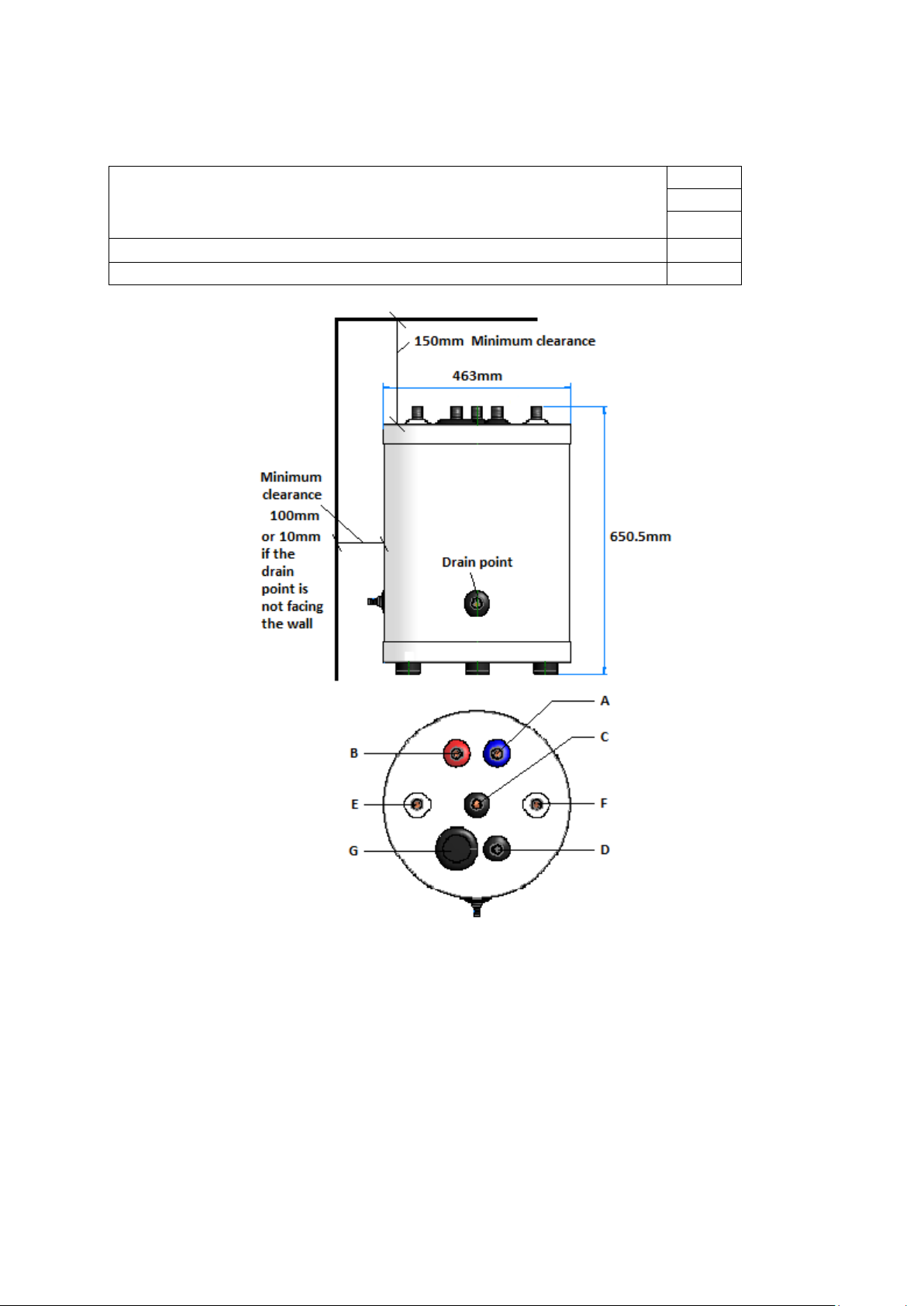
5.0 FLOWSMART CYLINDER CONNECTIONS + CLEARANCES
Minimum clearances for servicing
Top
Side
Side at drain point position
150mm
10mm
100mm
Lift weight empty
24 Kg
Weight full Inc. DHW and Primary circuits
80 Kg
A Mains water inlet ¾ BSP (Blue collar)
B Hot water outlet ¾ BSP (Red collar)
C Primary Return ¾ BSP (Black collar)
D Primary Flow ¾ BSP (Black collar)
E Secondary circulation ¾ BSP (White collar)
F Secondary circulation ¾ BSP (White collar)
G Plugged connection 11/4” BSP (for optional immersion)
Note: It is recommended that the drain point and thermostat/sensor are easily accessible for servicing
and adjustment.

6
6.0 FLOWSMART SYSTEM OPTIONS
The floor standing* FlowSmart system is available in two options:
1.) An Alpha InTec 40GS2 combination boiler with built in GasSaver, and floor mounted
50L thermal store
Or
2.) An Alpha E-Tec combination boiler**, separate GasSaver and floor mounted 50L
thermal store.
The system is controlled using either an optional Alpha E-Tec system diverter kit (plus
optional Alpha Climatic controller recommended) or a standard S plan controls kit can
be used.
It is important to purchase the correct FlowSmart system components and controls to
ensure the system works efficiently and as intended.
Note: Please ensure you have all kit components and controls BEFORE
commencing installation.
* Wall hung FlowSmart is a separate product and has separate installation instructions.
** For FlowSmart systems using other Alpha combination boilers please see previous
installation instructions
7.0 INSTALLATION
When delivered on site do not unpack until ready for installation and store in a dry
area. Depending on the system type you have, FlowSmart should be installed as
shown in the sections below.
Note: Please ensure you have all kit components and controls BEFORE
commencing installation.
7.1 FLUSHING
If it is not possible to clean the system before fitting the new boiler, the system should
be cleaned using a proprietary cleaner and a magnetic filter connected in the return
before the boiler as this is the most effective method of ensuring that any magnetite and
rust particles are prevented from entering and damaging the boiler. Once the system
condition has been restored, an effective magnetic filter and strainer should be fitted
permanently to the system as a method of collecting any magnetite and rust from the
system during operation.
7
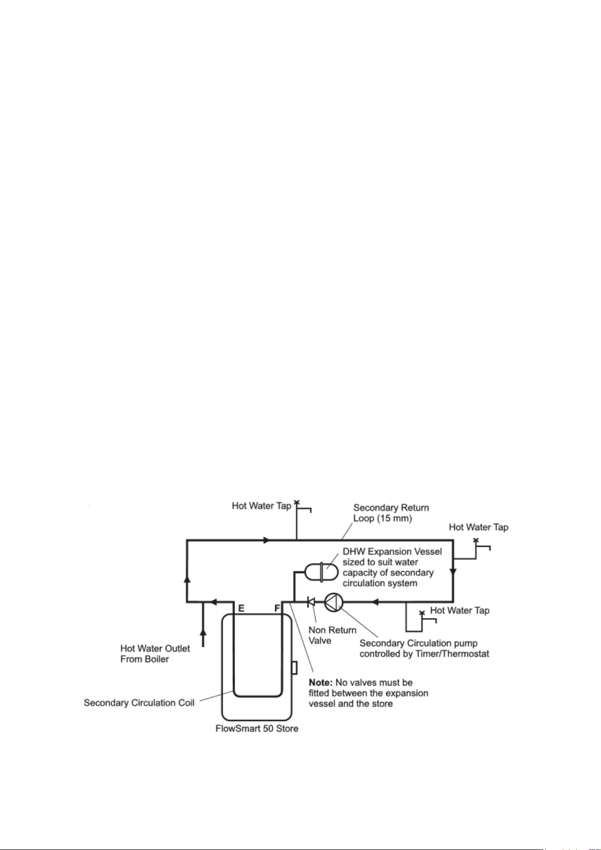
7.2 SECONDARY CIRCULATION (OPTIONAL)
Note: Additional fittings will be required to connect to the cylinder secondary
circulation connections – 3.019591 x 2no. (3/4" BSP to 15mm)
The FlowSmart 50 cylinder incorporates a secondary circulation coil in the store
(connections E & F)
A DHW expansion vessel (not included) of the correct size must be fitted to the
secondary circulation system.
The vessel must be a minimum of 10% of the secondary pipe work volume. e.g. if the
secondary circulation circuit has a water volume of 20 litres then the vessel size must
be 2 litres.
The vessel pre-charge must be set to the same pressure as the static mains water
supply.
The secondary circulation pump should be controlled by a timer and correspond with
the timer settings of the FlowSmart system i.e. do not operate the pump when the store
is not heated.
A thermostat should also be used on the secondary circulation pump control and set
such that it does not exceed the FlowSmart cylinder thermostat setting.
Ensure there are no dead legs or areas where there is no circulation within the pipe
work of the secondary circulation system.
Optional Secondary Circulation Example.
8
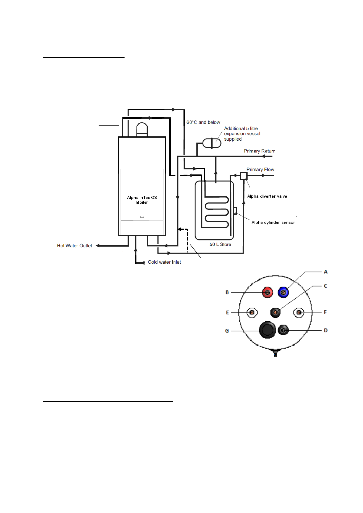
7.3 SYSTEM TYPE 1
InTec 40GS2 boiler with floor standing cylinder + Alpha Diverter +
Alpha Controls (1 CH zone)
Cylinder connections
A From top boiler connection ¾ BSP (Blue collar)
B Back to top boiler connection ¾ BSP (Red collar)
C Primary Return ¾ BSP (Black collar)
D Primary Flow ¾ BSP (Black collar)
E Secondary circulation ¾ BSP (White collar)
F Secondary circulation ¾ BSP (White collar)
G Plugged immersion heater connection 11/4 BSP
For optional DHW secondary circuit schematic (if
required), see page 7
Recommended Alpha Equipment List
Alpha Intec 40GS2 boiler (3.028276)
FlowSmart 50 (6.2003020) floor standing cylinder c/w cylinder connection kit.
Boiler top pipework connection kit (3.022913)
Alpha E-Tec diverter kit (6.5500048) complete with 3-port valve and cylinder sensor
Controls:
Alpha Climatic controller (3.022143 Wireless or 3.022144 hard wired)
Optional Alpha external weather compensation probe (3.022383)
Top Connection
Kit
FROM B
TO A
External bypass
recommended
B A C D
9
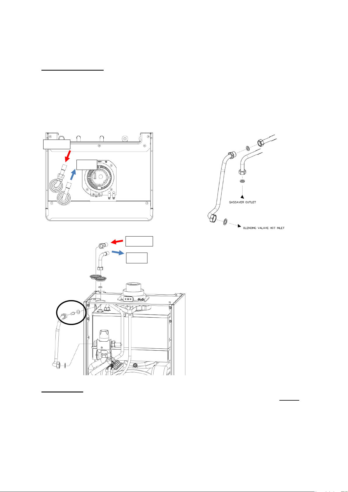
FITTING THE BOILER
Intec 40GS2 Boiler
The boiler and flue must be mounted as described in the instructions supplied with the
boiler.
When installing a floor standing cylinder to an InTec 40 GS2 boiler, a pipe kit MUST be
used to convert the top connections to connect 15mm copper pipe (part number
3.022913). Installation pipe work can be installed behind the boiler if required.
Fig 2 Top connection kit (3.022913)
IMPORTANT
To achieve maximum DHW flow rate the inlet mesh filter and flow regulator MUST be
removed from the brass inlet manifold of the boiler cold inlet connection (not shown).
The flow regulator should be discarded, and the mesh filter put into the top connection
kit joint as shown above.
TO A
FROM B
TO A
FROM B

10
FIT THE FLOWSMART PRIMARY STORE
1. Locate the primary store as close to the boiler as possible ensuring there are at least
the minimum clearances available.
2. The primary flow and return pipe work to the store should be no more than 1.5m in
length. The pipe work must be insulated.
3. Ensure the floor on which the store is mounted is capable of withstanding the weight
of the store, i.e. 80 kg.
Note: If an immersion heater is fitted, sufficient top clearance must be allowed to enable
the immersion heater to be replaced.
4. Fit the 3/4" BSP fittings supplied to the primary store connections using the washers
supplied as follows:-
a. The 3/4" BSP to 22 mm fittings to the primary flow and return connections (with the
black collars)
b. The 3/4" BSP to 15 mm fittings to the cold inlet (with the blue collar) and hot water
outlet connections (with the red collar).
5. Connect the pipework - Refer to the relevant schematic drawing for your installation
type.
6. Fit the 5 litre expansion vessel (using the 'T' connection supplied) to the primary
return pipework from the store.
7. Connect the Alpha E-Tec diverter kit 3-port valve as shown below.
Note: If a DHW secondary circulation circuit is used, see page 7.
8. Connect all cold mains and hot water pipework as shown
9. Thoroughly flush out all water pipework.
CONTROL VALVE INSTALLATION
Alpha E-Tec Diverter Kit (6.5500048)
Install 3 port valve supplied with Alpha E-Tec diverter kit according to instructions
provided.
Note: When using the optional Alpha E-Tec Diverter Kit, the valve must be
connected in the following way:
Connection AB to boiler flow
Connection A to heating flow
Connection B to FlowSmart cylinder primary flow (cylinder connection D)
Heating = A
B = Flowsmart
AB = Boiler Flow
11
EXTERNAL BYPASS
An external automatic type bypass is strongly recommended.
CYLINDER SENSOR
The FlowSmart cylinder insulation has a label indicating the location of the sensor
mounting position.
Cut a slit in the insulation and fix the sensor directly to the cylinder metal surface
ensuring good contact. Fix into position using foil tape. Once fitted, cover sensor with
insulation if necessary.
Note: Do not simply push the sensor into the foam insulation as it will not read
temperature correctly.
ELECTRICAL CONNECTIONS
All electrical wiring must be carried out by a competent person to BS 7671 Requirements for Electrical Installations, IEE Wiring Regulations.
Connect the mains supply to the boiler terminal block as described in the instructions
supplied with the boiler.
Note: An internal clock should not be fitted to the boiler when a FlowSmart
system is connected.
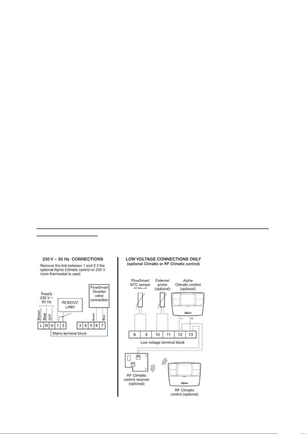
Alpha InTec 40GS2 boiler with floor standing cylinder + Alpha Diverter + Alpha
Controls (1 CH zone)
General wiring connections:
 Loading...