

Page 1

Installation and Servicing
Instructions
Alpha FlowSmart 25 and 50
Hot Water System incorporating a Flue Gas Heat
Recovery Device, Primary Store and an Alpha CD
Condensing Combination Boiler
For Technical help or for Service call ...
ALPHA HELPLINE
Tel: 0870 3001964
Nepicar House, London Road,
Wrotham Heath, Sevenoaks,
Kent TN15 7RS
Building Regulations Approved
Certificate No. ETC12908
Zenex SuperFlow Technology
Patent Protected No. 2420174
Other Patents Pending
Leave these instructions with the User
Page 2

CONTENTS
1 Introduction ....................................... 2
2 Technical data................................... 3
3 General information........................... 5
4 Installation......................................... 8
5 Commissioning ................................. 10
6 Routine inspection............................. 11
7 Short parts list ................................... 11
8 Inspection history .............................. 12
1 INTRODUCTION
The Alpha FlowSmart system is a domestic hot water system designed to provide a high level of performance more
efficiently.
The combination boiler will provide both central heating and domestic hot water at mains pressure.
The complete FlowSmart package consists of an Alpha CD35C condensing combination boiler, GasSaver, primary
storage cylinder (25 or 50 litre), expansion vessel and fittings kit. A cylinder thermostat and a 'Y' or 'S' plan control
system kit will also be required for the installation (not supplied).
IMPORTANT
The Alpha FlowSmart system must be installed as detailed in these instructions. The boiler and GasSaver must be
installed in accordance with the installation instructions supplied with them. Failure to do so will negate the warranty
supplied with this unit.
The FlowSmart system has been approved to the relevant requirements of the Building Regulations for primary hot water
storage systems and to the UK Water Regulations.
It is the law that all gas appliances are installed by a competent person, ie CORGI registered personnel, in accordance
with the following recommendations:-
Current Gas Safety (Installation and Use) Regulations
All current Building Regulations issued by the Department of the Environment, i.e. Approved Document L1.
Building Standards (Scotland) (Consolidation) Regulations issued by the Scottish Development Department
UK Water Regulations/Byelaws (Scotland)
Health & Safety Document No. 635 (The Electricity At Work Regulations 1989)
The installation should also be in accordance with the following British Standard Codes of Practice:BS 5440:1:2000 Flues
BS 5449:1990 Forced circulation hot water systems
BS 5546:2000 Installation of hot water supplies for domestic purposes
BS 6700:1997 Design, installation, testing and maintenance of services supplying water
BS 6798:2000 Installation of gas fired hot water boilers
BS 6891:1998 Gas installation
BS 7593:1992 Code of Practice for treatment of water in heating systems
BS 7671:2001 Requirements for electrical installations, IEE Wiring Regulations
Failure to install any part of the FlowSmart system correctly could lead to prosecution. It is in your own interest and that
of safety to ensure that the law is complied with.
Manufacturer's instructions must NOT be taken in anyway as over-riding statutory obligations.
Notes: 1. Alpha CD condensing flue components must be used when the GasSaver is used with an Alpha CD boiler.
2. It is essential that the primary system is thoroughly cleaned and flushed when fitting the FlowSmart system.
All cleaning agent must be removed and inhibitor added to the system - failure to do so will invalidate the warranty.
Alpha FlowSmart 25 and 50 - Contents/Introduction
2
Page 3

2 TECHNICAL DA T A
2.1 GENERAL
Cylinder External Dimensions 25 L
50 L
Outer Case
Cylinder Insulation Material
Cylinder Insulation Thickness
Standing Energy Loss of Cylinder 25 L
50 L
2.2 DHW SYSTEM
Maximum Inlet Water Pressure
Minimum Inlet Water Pressure
Maximum Water Flow Rate
Minimum Water Flow rate
Outlet Water Temperature (approx. max.)
FlowSmart Cylinder
Mains Water Inlet Pipe Connection
Mains Water Outlet Pipe Connection
Coil Material
DHW Coil Water Capacity 25 L
50L
Secondary Circulation Connections 50L only
Secondary Circulation Coil Capacity 50L only
345 mm Dia. x H530 mm
470 mm Dia. x H650 mm
Steel - White paint
PUR foam
50 mm
0.6 kW/24hr (0.8 Watts/litre)
1.1 kW/24hr (0.8 Watts/litre)
*5 bar
0.2 bar
18 l/min
2.5 l/min
62°C
3/4" BSP to 15 mm (fitting supplied)
3/4" BSP to 15 mm (fitting supplied)
Copper
2 L
3.5 L
3/4" BSP
0.28 L
* Note: If inlet water
pressure is above 5
bar a pressure
reducing valve must
be fitted
2.3 PRIMARY SYSTEM
Maximum Working Pressure
Minimum System Pressure
Maximum System Temperature (approx.)
Boiler Pressure relief Valve Setting
Boiler Exp. Vessel (pre-charge press.)
Recommended System Pressure (cold)
FlowSmart Cylinder
Flow and Return Connections
Cylinder Material
Cylinder Capacity 25 L
50 L
Plugged Connection (immersion heater if required)
3/4" BSP to 22 mm (fittings supplied)
2.4 COMPONENTS
Blending Valve Setting (boiler inlet) - Required temperature setting
Blending Valve Connections
Additional Primary System Expansion Vessel Capacity
Connection
Pre-Charge Pressure
2.5 bar
0.5 bar
82°C
3 bar
8 L at 0.8 bar
1.0 bar
Mild Steel
24 L
50 L
1 1/4" BSP
30°C
15 mm
5 L
1/2" BSP
1 bar
Alpha FlowSmart 25 and 50 - Technical Data
3
Page 4
2.5 INSTALLATION
Minimum Clearances for Servicing Top
(Refer to Fig. 1) Drain Point Side only
Lifting Weight (empty) 25 L
50 L
Weight (full) including DHW and Primary Circuit 25 L
50 L
* 150 mm
100 mm
16 kg
29 kg
42 kg
82 kg
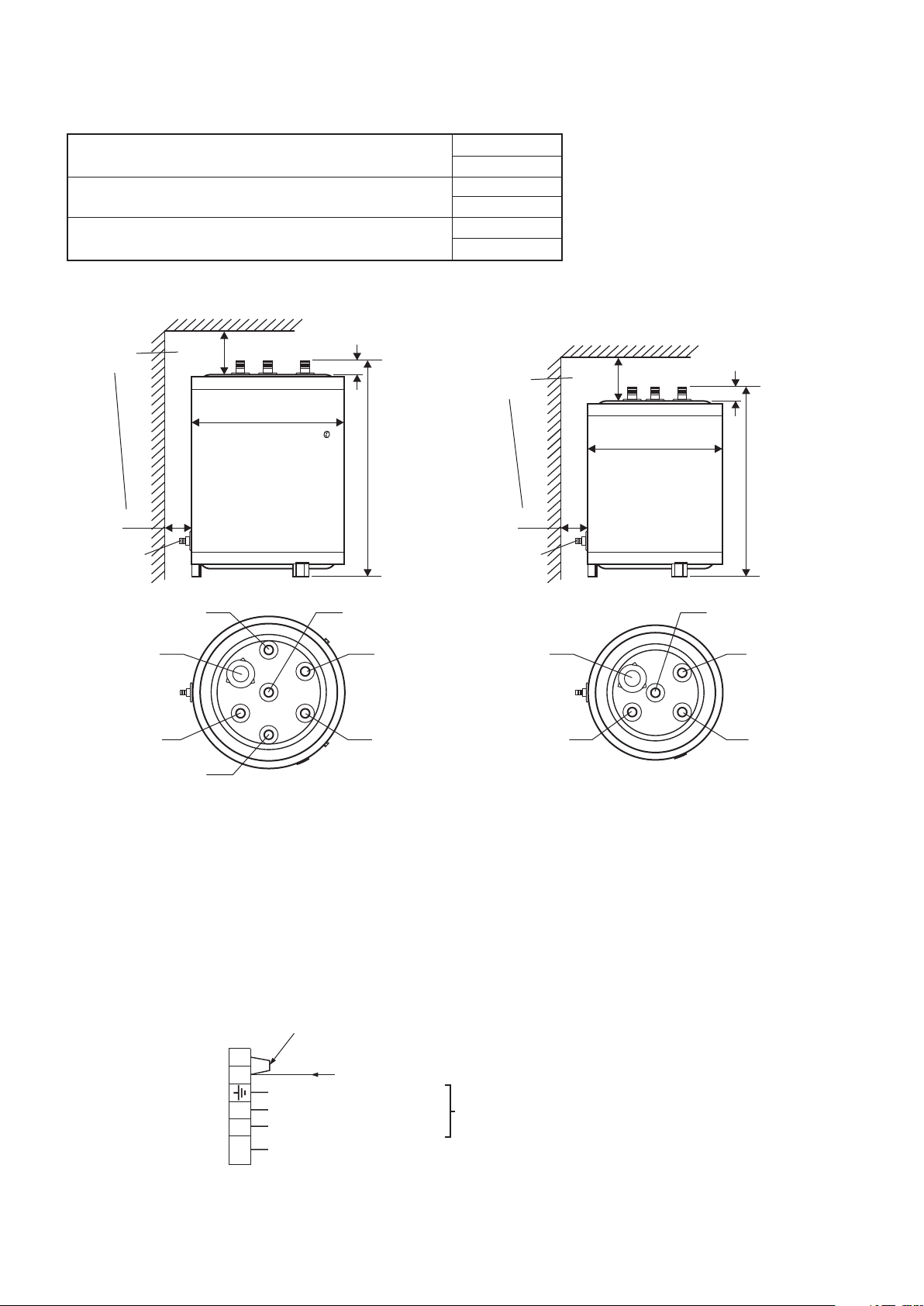
2.6 FLOWSMART CYLINDER LOCATION and CONNECTIONS
* Note: If an immersion heater is fitted,
sufficient top clearance must be
allowed to enable the immersion
heater to be replaced
*
Minimum
clearances
150 mm
470 mm Dia.
50 L
100 mm 100 mm
E
G
D
F
38 mm
650 mm
C
B
A
Minimum
*
clearances
Drain PointDrain Point
150 mm
345 mm Dia.
25 L
E
D
38 mm
530 mm
C
B
A
Connections - 50 L Connections - 25 L
- Mains Water Inlet 3/4" BSP (Blue collar)
A
- Hot Water Outlet 3/4" BSP (Red collar)
B
- Primary Return 3/4" BSP(Black collar)
C
- Primary Flow 3/4" BSP (Black collar)
D
- Secondary Circulation 3/4" BSP (White collar)
E
- Secondary Circulation 3/4" BSP (White collar)
F
- Plugged Immersion Heater Connection 11/4" BSP
G
2.7 ELECTRICAL CONNECTIONS
Remove link to connect
external control
2
1
Earth
(Green/Yellow Wire)
Neutral
NL
Permanent Live
Fuse
F2A
Alpha FlowSmart 25 and 50 - Technical Data
4
- Always fit fast blow 2A
- Mains Water Inlet 3/4" BSP (Blue collar)
A
- Hot Water Outlet 3/4" BSP (Red collar)
B
- Primary Return 3/4" BSP (Black collar)
C
- Primary Flow 3/4" BSP (Black collar)
D
- Plugged Immersion Heater Connection 11/4" BSP
E
Fig. 1
230/240V Switched Live from S or Y plan wiring junction box
(Blue Wire)
(Brown Wire)
230/240V ~ 50Hz
Fuse supply 3A
Fig. 2 - Boiler terminal block
Page 5

3 GENERAL INFORMATION
Hot Outlet Temp °C FlowSmart 50
Hot Outlet Temp °C FlowSmart 25
Hot Outlet Temp °C 200 L Store
Hot Outlet Temp °C 200 L Store Blended
3.1 HOW DOES THE FLOWSMART SYSTEM WORK
The Alpha FlowSmart system has been designed to deliver domestic hot water at a high level of performance more
efficiently, for example 18 l/min for temperatures of 50°C and above for long periods of demand using less energy than a
typical hot water storage system utilising a large cylinder.
The cold water supply first passes through the GasSaver where the reclaimed heat from the hot flue gasses is used to
pre-heat the cold water supply. This pre-heated water then passes through the coil in the primary store where it is heated
to a higher temperature. This hot water then passes to the blending valve where it is mixed with cold water direct from the
supply and enters the cold inlet of the combination boiler at a temperature of approximately 30°C. The boiler then heats
the water to the required temperature. See the performance graph Fig. 3.
When the flow of hot water is stopped, the FlowSmart store is reheated and then the system is ready to provide the same
performance again.
Outlet temperature for 30 mins at a flow rate of 18 L/min
Temp °C
80
70
60
50
40
30
20
10
0
0
5
10 15 20
Time Minutes
Hot Outlet Temp °C FlowSmart 50
Hot Outlet Temp °C FlowSmart 25
Hot Outlet Temp °C 200 L Store
Hot Outlet Temp °C 200 L Store Blended
25 30
Fig. 3 - FlowSmart vs 200 L store performance
3.2 TYPES OF INSTALLATION
Depending on the type of control system used the FlowSmart should be installed as shown in one of the following schematics.
The primary store should be positioned as close as possible to the boiler with the primary flow and return pipework to the store
no more than 1½ m in length. This pipework must be insulated.
Using the 'S' plan control system
Hot Water Outlet
Cold Water Out
GasSaver
Alpha
Combination
Boiler
30°C
Blending Valve
80°C and below
60°C and below
25 or 50 L Store
Fig. 4
Alpha FlowSmart 25 and 50 - General Information
Additional 5 litre
expansion vessel
supplied
Primary Return
Primary Flow
2 Port Zone
Valves
Cylinder
Thermostat
Cold water Inlet
5
Page 6

Using the 'Y' plan control system
60°C and below
Additional 5 litre
expansion vessel
supplied
Primary Return
Primary Flow
3 Port Zone
Valve
Cylinder
Thermostat
Cold water Inlet
Hot Water Outlet
Cold Water Out
30°C
Blending Valve
GasSaver
Alpha
Combination
Boiler
25 or 50 L Store
80°C and below
Fig. 5
3.3 DOMESTIC HOT WATER SYSTEM
Note: Before installation, check that the incoming mains water supply is adequate to provide the required flow rates.
The minimum flow rate needed for the flow switch and burner to operate is 2.5 litres/min.
The incoming mains water pressure should be between 0.2 and 5 bar to ensure efficient operation. If the pressure is
above 5 bar a pressure reducing valve must be fitted.
To ensure economic use, the pipe runs should, where possible, be in 15 mm copper pipe and be as short as possible,
also where possible the pipework should be insulated to reduce heat loss.
All taps and mixing valves used with the hot water system must be suitable for operating at a mains pressure of up to 8 bar.
Showers - A shower may be used with the boiler if required.
If a loose or flexible head type shower is used it may require the fitting of a double check valve, to comply with Water Bye Law 17.
Bidets - No anti-syphonage arrangements are necessary, provided the outlets are shrouded and it is not possible to
attach a temporary hand held spray. A supply of direct mains fed hot and cold water is permitted provided the appliance
is of the over-rim flushing type.
Before the mains water supply pipe is connected to the boiler, it should be thoroughly flushed out to avoid the danger of
dirt or foreign matter entering the boiler.
Alpha FlowSmart 25 and 50 - General Information
6
Page 7

3.4 FLUSHING THE HEATING SYSTEM
It is essential that the primary system is thoroughly cleaned and flushed when fitting the FlowSmart system. If a cleaning
agent is used, it must be flushed out before inhibitor is added to the primary system. Cleaning agent and inhibitor must be
applied in accordance with the manufacturers instructions. Only Fernox and Sentinel are acceptable for use. Further
information can be obtained from Fernox (Tel: 0179 9521133) or Sentinel (Tel: 0800 3894670).
All cleaning agent must be removed and inhibitor added to the system, failure to do so will invalidate the warranty.
The system should be flushed in accordance with BS 7593 and BS 5449. The following procedures are recommended:
1. Installing onto a new system:a.Fill the system, vent at high points, at pump and radiators.
b.Check for leaks.
c.Rapidly drain the system.
d.If required, chemically clean the system as instructed by the recommended cleaner manufacturer.
Note: Ensure that the system is flushed to remove any remains of the cleaner.
e.If chemical cleaner is not used to clean the system:-
i) Refill the system.
ii) Switch on the boiler and allow the system to heat up to the normal operating temperature.
iii) Rapidly drain the system while the water is still hot.
iv) Refill the system.
f. As required, add the recommended inhibitor to the system as instructed by the inhibitor manufacturer.
g.Recheck for leaks.
2. Installing onto an existing system, clean the system before fitting the new boiler:a.If the old boiler is still working:-
i) Switch on the boiler and allow the system to heat up to the normal operating temperature.
ii) Rapidly drain the system while the water is still hot.
iii) Refill and chemically clean the system as instructed by the recommended cleaner manufacturer.
iv) Ensure the system is flushed to remove any remains of the cleaner.
v) Fit the new boiler.
b.If the old boiler is not working:-
i) Rapidly drain the system.
ii) Remove the old boiler.
iii) Flush the system through.
iv) Fit the new boiler.
v) Refill and chemically clean the system as instructed by the recommended cleaner manufacturer.
vi) Ensure the system is flushed to remove any remains of the cleaner.
c.As required, add the recommended inhibitor to the system as instructed by the inhibitor manufacturer.
d.Check for leaks.
3.5 CENTRAL HEATING SYSTEM
Refer to the instructions supplied with the boiler for full information. However the FlowSmart has been supplied with a 5
litre expansion vessel for fitting to the primary return pipework between the FlowSmart primary store and the boiler (See
Figs. 4 and 5). This is to allow for the additional expansion required when fitting the FlowSmart primary store. The precharge of the expansion vessel should be 1 bar.
3.6 IMMERSION HEATER
If an immersion heater is fitted, it must incorporate a thermostat and thermal cut-out.
Note: Immersion heaters without thermal cut-outs must not be fitted.
The immersion heater must be installed in accordance to current electrical requirements for installation BS 7671 and
must be fused as stated on the heater. A label will be supplied with the immersion heater detailing the watts, voltage,
type, length and the BS or equivalent it complies with. This label must be fitted to the FlowSmart store.
Alpha FlowSmart 25 and 50 - General Information
7
Page 8

3.7 ALPHA FLOWSMART 50 - SECONDARY CIRCULATION - See Fig. 6
1. If a DHW secondary circulation circuit is required, you must use the FlowSmart 50 because it incorporates a secondary
circulation coil in the store.
2. A DHW expansion vessel the correct size must always be fitted to the secondary circulation system, eg. 5 litre expansion
vessel is suitable for capacities of the secondary circulation system upto 50 litres. This expansion vessel should be
charged to 3.5 bar.
3. The secondary circulation pump should be controlled by a timer, and correspond with the timer settings for the FlowSmart
system, i.e. do not operate the pump when the store is not heated.
4. Ensure the setting of the secondary circulation thermostat setting does not exceed the FlowSmart store temperature setting,
i.e. cylinder thermostat setting.
5. Ensure there are no dead areas or areas where there is no circulation within the pipework of the secondary circulation system.
GasSaver
Alpha CD35C
Combination
Boiler
Hot Water Outlet
From Boiler
Secondary Circulation Coil
Hot Water Tap
EF
FlowSmart 50 Store
Secondary Return
Loop (15 mm)
DHW Expansion Vessel
sized to suit water
capacity of secondary
circulation system
Non Return
Valve
Note: No valves must be
fitted between the expansion
vessel and the store
Secondary Circulation pump
controlled by Timer/Thermostat
Hot Water Tap
Hot Water Tap
Fig. 6
4 INST ALLATION
4.1 UNPACKING
Note: When delivered on site do not unpack until ready for installation and ensure to store in a dry area.
1. The following items are supplied in the FlowSmart package:
a. An Alpha CD35C condensing combination boiler
b. An Alpha GasSaver GS-1 complete
c. A FlowSmart 25 or 50 primary store
e. A FlowSmart expansion vessel and fittings kit (Part No. 3.019505) which contains the items shown in Fig. 7
2 x 3/4" BSP to 22 mm fittings
2 x 3/4" BSP to 15 mm fittings
5 litre expansion vessel
Fig. 7 - Expansion vessel kit contents
Alpha FlowSmart 25 and 50 - General Information/Installation
8
2 x 1/2" wahers
'T' fitting
2 x 22 mm to 1/2" BSP
6 x 3/4" washers
Page 9

2. The following items are required in addition to the above.
a. The required flue terminal assembly for the boiler
b. A cylinder thermostat
c. An 'S' or 'Y' plan control system kit, including programmer and room thermostat.
4.2 FIT THE BOILER AND GASSAVER
The boiler, flue and GasSaver must be fitted as described in the instructions supplied with the boiler and the GasSaver.
4.3 FIT THE FLOWSMART PRIMARY STORE
1. Locate the primary store as close to the boiler as possible ensuring there are the minimum clearances available as given in
Section 2.5 and shown in Fig. 1.
Ensure the floor on which the store is mounted is capable of withstanding the weight of the store, i.e. 42 kg for 25 litre model
or 82 kg 50 litre model.
Note: If an immersion heater is fitted, sufficient top clearance must be allowed to enable the immersion heater to be replaced.
2. Connect the pipework - Refer to Figs. 1 and 4 or 5.
a. Fit the 3/4" BSP to 22 mm fittings and 3/4" BSP to 15 mm fittings supplied, to the primary store connections using the
washers supplied as follows:The 3/4" BSP to 22 mm fittings to the primary flow and return connections (with the black collar) and the 3/4" BSP to 15 mm
fittings to the cold inlet (with the blue collar) and hot water outlet connections (with the red collar).
Note: 50 L only - If a DHW secondary circulation circuit is used, the connections with the white collar (E and F) must be
connected to the circuit. Refer to Section 3.7 and Fig. 6.
b. Thoroughly flush out all water pipework. Refer to Section 3.4.
c. Connect all primary system pipework referring to Fig. 4 or 5. Ensure that the following are connected:-
Connect the 5 litre expansion vessel using the 'T' connection supplied, to the primary return pipework from the store.
Connect the 'S' or 'Y' plan valves as shown in Fig. 4 or 5.
d. Connect all cold mains and hot water pipework as shown in Fig. 4 or 5. Ensure that the blending valve is connected to
the hot water outlet pipework from the store also shown in Fig. 4 or 5.
4.4 FIT THE CYLINDER THERMOSTAT
1. Remove the six screws securing the 80 x 160 mm cover located on the side of the primary store, just above the drain tap
and remove the cover.
2. Cut away the insulation around the 80 x 160 mm hole until the metal side of the store is exposed.
3. The cylinder thermostat can then be located within the hole and secured as detailed in the instructions supplied with the
thermostat.
4.5 ADJUST THE SEASONALITY VALVE - See Fig. 8
Adjust the seasonality valve on the combination boiler by turning the adjusting screw fully clockwise, as shown in Fig. 8.
This will allow the maximum flow rate through the boiler.
Seasonality
valve adjusting
screw
Underneath the
combination boiler
Seasonality
valve
Wall
Fig. 8 - Location of seasonality valve
Alpha FlowSmart 25 and 50 - Installation
9
Page 10

4.6 ELECTRICALLY CONNECT ALL CONTROLS
Note: All electrical wiring must be carried out by a competent person to BS 7671 - Requirements for Electrical
Installations, IEE Wiring Regulations.
1. Connect the mains supply to the boiler terminal block as described in the instructions supplied with the boiler.
The boiler electrical connections are shown in Fig. 2 of these instructions.
Note: An internal clock should not be fitted to the boiler when a FlowSmart system is connected. An external 2-channel
clock must be used instead.
2. Connect the cylinder thermostat, 2-channel programmer, room thermostat and zone valves as described in the
instructions supplied with the 'S' or 'Y' plan control system kits.
5 COMMISSIONING
1. Fill all the systems, i.e. primary and secondary circuits and check for leaks. Refer to the boiler instructions.
2. Refer to Section 3.4 in these instructions and ensure the primary system has been flushed and cleaned and inhibitor
added to the primary system.
Note: All cleaning agent must be removed and inhibitor added to the primary system, failure to do so will invalidate the
warranty.
3. Commission the boiler and GasSaver as described in the boiler and GasSaver installation instructions.
4. Ensure that the boiler hot water thermostat is set to position 9 (maximum) and the boiler central heating thermostat is set
to a position above 7 to max. as shown in Fig. 9.
Domestic
Hot Water Thermostat
SET TO 9 (MAXIMUM)
OFF
0
A
B
C
D
1
2
RESET
3
SELECTOR THERMOSTAT THERMOSTAT
1
2
9
3
4
8
5
7
6
SET ABOVE 7 UPTO 9 (MAXIMUM)
9
8
Central
Heating Thermostat
1
2
3
4
5
7
6
2
3
1
04
bar
Fig. 9
5. Ensure that the blending valve positioned between the FlowSmart store and the boiler water inlet is set to approximately
30°C, i.e. about the minimum setting.
6. Ensure that the cylinder thermostat is set at or below the boiler central heating thermostat temperature setting.
Alpha FlowSmart 25 and 50 - Installation/Commissioning
10
Page 11

6 ROUTINE INSPECTION
It is recommended that the FlowSmart cylinder should be subject to a general condition inspection at each boiler
maintenance interval.
If the system pressure exceeds 2.5 bar when operating at maximum temperature, the additional 5 litre expansion vessel
(refer to Fig. 4 or 5) as well as the boiler expansion vessel should be checked and re-pressurised, if necessary.
Notes: 1. Check the expansion vessel charge only when the system pressure is zero.
2. The expansion vessel pressure should be charged to 1 bar.
7 SHORT PARTS LIST
Item Qty. Part No.
5 litre expansion vessel
Drain tap
Connector ¾" BSP to 15 mm
Connector ¾" BSP to 22 mm
'T' connector 22 mm to ½" BSP
Plug 1¼" BSP
'O' ring for 1¼" BSP plug
Box spanner for 1¼" connection
1
1
2
2
1
1
1
1
1.026991
6.2003030
3.019591
3.019592
3.019539
6.0001140
6.2003040
6.2003045
Alpha FlowSmart 25 and 50 - Routine Inspection/Short Parts List
11
Page 12

8 INSPECTION RECORD
It is recommended that the FlowSmart is inspected regularly and that you complete the appropriate Inspection Record
below.
Service Provider: Before completing the appropriate Inspection Record below, please ensure you have carried out the
boiler service as described in the boiler instruction manual.
INSPECTION 1: Date .................................................................
Engineers Name .........................................................................
Company Name ..........................................................................
Telephone No..............................................................................
CORGI ID card serial No. ...........................................................
Comments ...................................................................................
.....................................................................................................
Signature .....................................................................................
INSPECTION 3: Date .................................................................
Engineers Name .........................................................................
Company Name ..........................................................................
Telephone No..............................................................................
CORGI ID card serial No. ...........................................................
Comments ...................................................................................
.....................................................................................................
Signature .....................................................................................
INSPECTION 5: Date .................................................................
Engineers Name .........................................................................
Company Name ..........................................................................
Telephone No..............................................................................
CORGI ID card serial No. ...........................................................
Comments ...................................................................................
.....................................................................................................
Signature .....................................................................................
INSPECTION 2: Date .................................................................
Engineers Name .........................................................................
Company Name ..........................................................................
Telephone No..............................................................................
CORGI ID card serial No. ...........................................................
Comments ...................................................................................
.....................................................................................................
Signature .....................................................................................
INSPECTION 4: Date .................................................................
Engineers Name .........................................................................
Company Name ..........................................................................
Telephone No..............................................................................
CORGI ID card serial No. ...........................................................
Comments ...................................................................................
.....................................................................................................
Signature .....................................................................................
INSPECTION 6: Date .................................................................
Engineers Name .........................................................................
Company Name ..........................................................................
Telephone No..............................................................................
CORGI ID card serial No. ...........................................................
Comments ...................................................................................
.....................................................................................................
Signature .....................................................................................
INSPECTION 7: Date .................................................................
Engineers Name .........................................................................
Company Name ..........................................................................
Telephone No..............................................................................
CORGI ID card serial No. ...........................................................
Comments ...................................................................................
.....................................................................................................
Signature .....................................................................................
Alpha Therm Limited.
Nepicar House, London Road, Wrotham Heath,
Sevenoaks, Kent TN15 7RS
Tel: 0870 3001964
email: info@alphatherm.co.uk
website:www.alpha-innovation.co.uk
INSPECTION 8: Date .................................................................
Engineers Name .........................................................................
Company Name ..........................................................................
Telephone No..............................................................................
CORGI ID card serial No. ...........................................................
Comments ...................................................................................
.....................................................................................................
Signature .....................................................................................
These instructions have been carefully prepared but we reserve the right to
alter the specification at any time in the interest of product improvement.
© Alpha Therm Limited 2008.
Manual compiled and designed by Publications 2000 - Tel: (01670) 356211 06/08/D215
 Loading...