

Page 1
x550 Series
Stackable 10Gigabit Intelligent Access Ethernet Switches
AlliedWare Plus™ v5.4.7A-0
AT-x550-18XTQ
AT-x550-18XSQ
Installation Guide for Stand-alone
Switches
613-002431 Rev. A
Page 2

Copyright © 2017 Allied Telesis, Inc.
All rights reserved. No part of this publication may be reproduced without prior written permission from Allied Telesis, Inc.
Allied Telesis, VCStack, and the Allied Telesis logo are trademarks of Allied Telesis, Incorporated. All other product names, company
names, logos or other designations mentioned herein are trademarks or registered trademarks of their respective owners.
Allied Telesis, Inc. reserves the right to make changes in specifications and other information contained in this document without prior
written notice. The information provided herein is subject to change without notice. In no event shall Allied Telesis, Inc. be liable for
any incidental, special, indirect, or consequential damages whatsoever, including but not limited to lost profits, arising out of or related
to this manual or the information contained herein, even if Allied Telesis, Inc. has been advised of, known, or should have known, the
possibility of such damages.
Page 3

Electrical Safety and Emissions Standards
Laser Safety EN60825
This product meets the following standards.
U.S. Federal Communications Commission
Radiated Energy
Note: This equipment has been tested and found to comply with the limits for a Class A digital device pursuant to Part 15
of FCC Rules. These limits are designed to provide reasonable protection against harmful interference when the
equipment is operated in a commercial environment. This equipment generates, uses , and can radiate radio frequency
energy and, if not installed and used in accordance with this instruction manual, may cause harmful interference to radio
communications. Operation of this equipment in a residential area is likely to cause harmful interference in which case
the user will be required to correct the interference at his own expense.
Note: Modifications or changes not expressly approved of by the manufacturer or the FCC, can void your right to operate
this equipment.
Industry Canada
This Class A digital apparatus complies with Canadian ICES-003.
Cet appareil numérique de la classe A est conforme à la norme NMB-003 du Canada.
RFI Emissions: FCC Class A, EN55032 Class A, EN61000-3-2, EN61000-3-3, VCCI Class A,
C-TICK, CE
Warning: In a domestic environment this product may cause radio interference in which case
the user may be required to take adequate measures.
EMC (Immunity): EN55024
Electrical Safety: EN60950-1 (TUV), UL 60950-1 (
CULUS
)
3
Page 4

Translated Safety Statements
Important: Safety statements that have the symbol are translated into multiple languages in the
Translated Safety Statements document at www.alliedtelesis.com/support.
4
Page 5

Contents
Preface ...............................................................................................................................................................................11
Document Conventions .......................................................................................................................................................12
Contacting Allied Telesis .....................................................................................................................................................13
Chapter 1: Overview ........................................................................................................................................................ 15
Front and Rear Panels ........................................................................................................................................................16
Management Panel .............................................................................................................................................................18
Features ..............................................................................................................................................................................19
x550 Models......... ... .. ...................................................................................................................................................19
1Gbps/10Gbps Twisted Pair Ports...............................................................................................................................19
1Gbps SFP or 10Gbps SFP+ Transceiver Slots..........................................................................................................19
40Gbps QSFP+ Transceiver Slots...............................................................................................................................20
LEDs.............................................................................................................................................................................20
Installation Options.......................................................................................................................................................21
Management Software and Interfaces .........................................................................................................................21
Management Methods..................................................................................................................................................21
1Gbps/10Gbps Twisted Pair Ports ......................................................................................................................................22
SFP+ Transceiver Slots............................................................... ... ... ..................................................................................23
QSFP+ Transceiver Slots....................................................................................................................................................24
eco-friendly Button...............................................................................................................................................................26
VCStack Feature............................... ... ... .................................... ..................................... ...................................................27
LEDs....................................................................................................................................................................................28
LEDs for the 1Gbps/10Gbps Twisted Pair Ports..........................................................................................................28
LEDs for the 1Gbps SFP and 10Gbps SFP+ Transceiver Slots ..................................................................................29
LEDs for the 40Gbps QSFP+ Transceiver Slots..........................................................................................................30
Switch ID LED..............................................................................................................................................................32
USB Port..............................................................................................................................................................................34
Console Port........................................................................................................................................................................35
Power Supply ......................................................................................................................................................................36
Chapter 2: Beginning the Installation ............................................................................................................................37
Reviewing Safety Precautions.............................................................................................................................................38
Choosing a Site for the Switch ............................................................................................................................................42
Unpacking the Switch..........................................................................................................................................................43
Chapter 3: Installing the Switch on a Table or in an Equipment Rack .......................................................................47
Installing the Switch on a Table or Desktop....................................................................................
Overview of Installing the Switch in an Equipment Rack.....................................................................................................49
Installing the Switch in an Equipment Rack with the AT-RKMT-J14 Brackets ....................................................................51
Required Items for the AT-RKMT-J14 Brackets...........................................................................................................51
Switch Orientations in the Equipment Rack.................................................................................................................51
Installing the Switch with the AT-RKMT-J14 Brackets .................................................................................................53
Installing the Switch in an Equipment Rack with the AT-RKMT-J15 Bracket......................................................................56
Required Items for the AT-RKMT-J15 Bracket.............................................................................................................56
Installing the Switch with the AT-RKMT-J15 Bracket ...................................................................................................56
Chapter 4: Installing the Switch on a Wall ....................................................................................................................63
Switch Orientations on a Wall..............................................................................................................................................64
Installation Guidelines .........................................................................................................................................................65
Tools and Material........................................................................................................................................................65
Plywood Base for a Wall with Wooden Studs......................................................................................................................67
.....................................48
5
Page 6

Contents
Installing a Plywood Base................................................................................................................................................... 69
Installing the Switch on a Plywood Base ............................................................................................................................ 70
Installing the Switch on a Concrete Wall............................................................................................................................. 73
Chapter 5: Powering On the Switch ...............................................................................................................................77
Powering On the Switch......................................................................................................................................................78
Monitoring the Initialization Processes................................................................................................................................81
Chapter 6: Configuring the Switch for Stand-alone Operations .................................................................................85
Determining the Stand-alone or Stacking Status of the Switch .......................................................................................... 86
Starting a Local Management Session............................................................................................................................... 87
Disabling the VCStack Feature........................................................................................................................................... 89
Configuring QSFP+ Transceiver Slots 17 and 21 for Breakout Cables.............................................................................. 91
Saving Your Changes and Rebooting the Switch............................................................................................................... 92
Specifying Ports in the Command Line Interface for Stand-alone Switches.......................................................................93
Chapter 7: Cabling the Networking Ports ......................................................................................................................95
Cabling the 1Gbps/10Gbps Ports in the AT-x550-18XTQ Switch....................................................................................... 96
Guidelines to Handling SFP, SFP+, and QSFP+ Transceivers.......................................................................................... 97
Installing 1Gbps SFP or 10Gbps SFP+ Transceivers in the AT-x550-18XSQ Switch........................................................ 98
Installing AT-SP10TW Direct Connect Twinax Cables in the AT-x550-18XSQ Switch .................................................... 101
Installing AT-QSFPSR4 or AT-QSFPLR4 Transceivers in QSFP+ Slots ................................................................
Installing AT-QSFPCU Cables in QSFP+ Slots................................................................................................................ 104
Chapter 8: Troubleshooting ..........................................................................................................................................107
......... 103
Appendix A: Technical Specifications .........................................................................................................................111
Physical Specifications ..................................................................................................................................................... 112
Environmental Specifications............................................................................................................................................ 113
Power Specifications......................................................................................................................................................... 114
Certifications.....................................................................................................................................................................115
RJ-45 Twisted Pair Port Pinouts.......................................................................................................................................116
RJ-45 Style Serial Console Port Pinouts.......................................................................................................................... 117
6
Page 7

Figures
Figure 1: Front Panels of the AT-x550-18XTQ and AT-x550-18XSQ Switches...................................................................16
Figure 2: Back Panel............................................................................................................................................................17
Figure 3: Management Panel ...............................................................................................................................................18
Figure 4: QSFP+ to SFP+ Breakout Cable...........................................................................................................................24
Figure 5: Link and Activity LEDs for the 1Gbps/10Gbps Ports on the AT-x550-18XTQ, Switch..........................................28
Figure 6: Link and Activity LEDs for the 1Gbps SFP and 10Gbps Slot+ Slots on the AT-x550-18XSQ Switch ...................29
Figure 7: LEDs for the 40Gbps QSFP+ Slots....................................................................................................................... 30
Figure 8: Switch ID LED.......................................................................................................................................................32
Figure 9: Switch ID LED.......................................................................................................................................................32
Figure 10: Switch ID LEDs in Low Power Mode...................................................................................................................33
Figure 11: AT-x550-18XTQ or AT-x550-18XSQ Switch Shipping Box.................................................................................43
Figure 12: Accessory Kit.......................................................................................................................................................44
Figure 13: Accessory Kit (Continued)...................................................................................................................................45
Figure 14: AT-RKMT-J14 Brackets and Switch....................................................................................................................49
Figure 15: AT-RKMT-J15 Bracket........................................................................................................................................49
Figure 16: AT-RKMT-J15 Bracket with Switches..................................................................................................................50
Figure 17: Bracket Holes......................................................................................................................................................51
Figure 18: AT-RKMT-J14 Bracket Holes..............................................................................................................................52
Figure 19: Switch Orientations with the Front Panel Facing the Front of the Equipment Rack............................................52
Figure 20: Switch Orientations with the Rear Panel Facing the Front of the Equipment Rack............................................. 53
Figure 21: Attaching the Handles to the AT-RKMT-J14 Brackets ........................................................................................54
Figure 22: Attaching the AT-RKMT-J14 Brackets to the Switch...........................................................................................54
Figure 23: Installing the Switch in an Equipment Rack.........................................................................................................55
Figure 24: Installing the AT-RKMT-J15 Bracket in the Equipment Rack..............................................................................56
Figure 25: Loosening the Two Thumbscrews on the Front of the AT-RKMT-J15 Bracket...................................................57
Figure 26: Sliding Out the Tray from the AT-RKMT-J15.......................................................................................................57
Figure 27: Removing the Plastic Feet from the Bottom Panel of the Switch........................................................................58
Figure 28: Placing a Switch in the AT-RKMT-J15 Bracket...................................................................................................59
Figure 29: Securing the Switch to the AT-RKMT-J15 Bracket..............................................................................................59
Figure 30: Sliding in the Bracket Tray.........................................................................................
Figure 31: Tightening the Two Thumbscrews on the AT-RKMT-J15 Bracket......................................................................61
Figure 32: Positions of the Switch on the Wall.....................................................................................................................64
Figure 33: Switch on the Wall with a Plywood Base.............................................................................................................67
Figure 34: Steps to Installing the Switch with a Plywood Base ............................................................................................68
Figure 35: Installing the Wall Brackets .................................................................................................................................71
Figure 36: Securing the Switch to the Plywood Base...........................................................................................................72
Figure 37: Marking the Locations of the Bracket Holes on a Concrete Wall ................................................... .....................74
Figure 38: Installing the Switch on a Concrete Wall.............................................................................................................75
Figure 39: Installing the Power Cord Retaining Clip.............................................................................................................78
Figure 40: Connecting the AC Power Cord ..........................................................................................................................79
Figure 41: Lowering the Power Cord Retaining Clip.............................................................................................................79
Figure 42: Connecting the Power Cord to an AC Power Source..........................................................................................80
Figure 43: Switch Initialization Messages.............................................................................................................................81
Figure 44: Switch Initialization Messages (Continued ).........................................................................................................82
Figure 45: Switch Initialization Messages (Continued ).........................................................................................................83
Figure 46: Connecting the Management Cable to the Console Port ....................................................................................87
Figure 47: User Exec Mode Prompt.....................................................................................................................................88
Figure 48: SHOW STACK Command...................................................................................................................................89
Figure 49: Moving to the Global Configuration Mode...........................................................................................................90
.......................................... 60
7
Page 8

Figures
Figure 50: Confirmation Prompt for the NO STACK ENABLE Command............................................................................90
Figure 51: Disabling VCStack...............................................................................................................................................90
Figure 52: Returning to the Privileged Exec Mode ...............................................................................................................92
Figure 53: Saving the Changes with the WRITE Command.................................................................................................92
Figure 54: PORT Parameter in the Command Line Interface...............................................................................................93
Figure 55: Removing the Dust Plug from an SFP Slot..........................................................................................................98
Figure 56: Installing an SFP Transceiver..............................................................................................................................99
Figure 57: Removing the Dust Cover from an SFP or SFP+ Transceiver............................................................................99
Figure 58: Positioning the SFP or SFP+ Handle in the Upright Position ............................................................................100
Figure 59: Connecting a Fiber Optic Cable to an SFP or SFP+ Transceiver ........................................................ .............100
Figure 60: Installing AT-SP10TW Cables ...........................................................................................................................101
Figure 61: Removing the Dust Cover from a Slot on the AT-SBx81XLEM/Q2 Expansion Module.....................................104
Figure 62: Sliding the AT-QSFPCU Cable into the Slot......................................................................................................105
Figure 63: RJ-45 Socket Pin Layout (Front View)...............................................................................................................116
8
Page 9

Tables
Table 1: Basic Features .......................................................................................................................................................19
Table 2: Twisted Pair Ports on the AT-x550-18XTQ Switch ................................................................................................22
Table 3: Link and Activity LEDs on the 1Gbps/10Gbps Ports on the AT-x550-18XTQ Switch ............................................28
Table 4: Link and Activity Status LEDs on the 1Gbps and 10Gbps Ports on the AT-x550-18XTQ Switch .........................29
Table 5: Link and Activity Status LEDs for the 40Gbps QSFP+ Transceiver Slots with QSFP+ Transceivers ...................31
Table 6: Link and Activity Status LEDs for the 40Gbps QSFP+ Transceiver Slots with Breakout Cables ..........................31
Table 7: PORT Parameter Format .......................................................................................................................................93
Table 8: Product Dimensions .............................................................................................................................................112
Table 9: Product Weights ..................................................................................................................................................112
Table 10: Ventilation Requirements ................................................................................................................................... 112
Table 11: Environmental Specifications .............................................................................................................................113
Table 12: Maximum Power Consumptions ........................................................................................................................114
Table 13: Input Voltages ....................................................................................................................................................114
Table 14: Heat Dissipation ................................................................................................................................................114
Table 15: Product Certifications .........................................................................................................................................115
Table 16: Pin Signals for 1Gbps or 10Gbps ......................................................................................................................116
Table 17: RJ-45 Style Serial Console Port Pin Signals .....................................................................................................117
9
Page 10

Tables
10
Page 11

Preface
Note
This guide contains the installation instructions for the x550 Series of
stackable 10 Gigabit, Layer 3 Ethernet switches. This preface contains the
following sections:
“Document Conventions” on page 12
“Contacting Allied Telesis” on page 13
This guide explains how to install the switches as stand-alone units.
For instructions on how to build a stack of switches with the Virtual
Chassis Stacking (VCStack
Installation Guide for Virtual Chassis Stacking.
™) feature, refer to the x550 Series
11
Page 12
Preface
Note
Caution
Warning
Document Conventions
This document uses the following conventions:
Notes provide additional information.
Cautions inform you that performing or omitting a specific action
may result in equipment damage or loss of data.
Warnings inform you that performing or omitting a specific action
may result in bodily injury.
12
Page 13

Contacting Allied Telesis
If you need assistance with this product, you may contact Allied Telesis
technical support by going to the Support & Services section of the Allied
Telesis web site at www.alliedtelesis.com/support. You can find links for
the following services on this page:
24/7 Online Support — Enter our interactive support center to
search for answers to your product questions in our knowledge
database, to check support tickets, to learn about RMAs, and to
contact Allied Telesis technical experts.
USA and EMEA phone support — Select the phone number that
best fits your location and customer type.
Hardware warranty information — Learn about Allied Telesis
warranties and register your product online.
Replacement Services — Submit a Return Merchandise
Authorization (RMA) request via our interactive support center.
x550 Series Installation Guide for Stand-alone Switches
Documentation — View the most recent installation and user
guides, software release notes, white papers, and data sheets for
your products.
Software Downloads — Download the latest software releases for
your managed products.
For sales or corporate information, go to www.alliedtelesis.com/
purchase and select your region.
13
Page 14

Preface
14
Page 15

Chapter 1
Note
Overview
This chapter contains the following sections:
“Front and Rear Panels” on page 16
“Management Panel” on page 18
“Features” on page 19
“1Gbps/10Gbps Twisted Pair Ports” on page 22
“SFP+ Transceiver Slots” on page 23
“QSFP+ Transceiver Slots” on page 24
“eco-friendly Button” on page 26
“VCStack Feature” on page 27
“LEDs” on page 28
“USB Port” on page 34
“Console Port” on page 35
“Power Supply” on page 36
This guide explains how to install the switches as stand-alone units.
For instructions on how to build a stack of switches with the Virtual
Chassis Stacking (VCStack
™) feature, refer to the x550 Series
Installation Guide for Virtual Chassis Stacking.
15
Page 16
Chapter 1: Overview
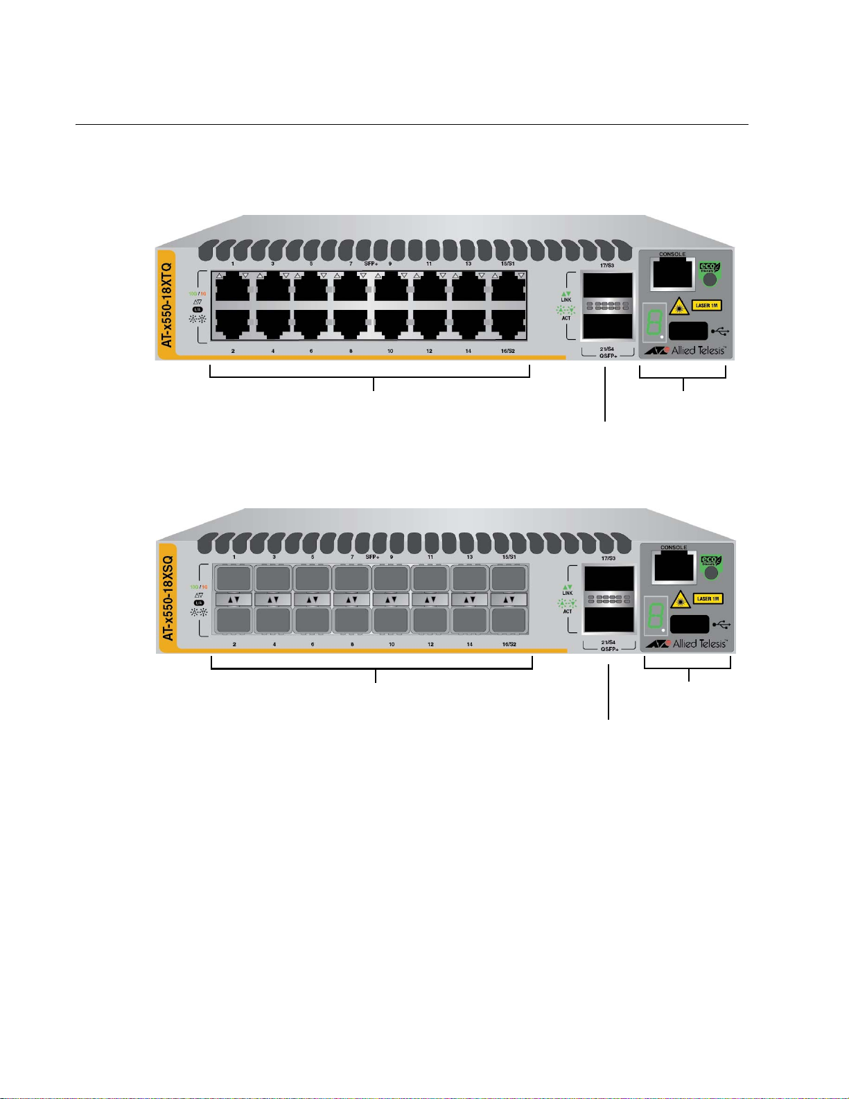
AT-x550-18XSQ
AT-x550-18XTQ
1Gbps or 10Gbps Ports
Management
Panel
40Gbps QSFP+
Transceiver Slots
Management
Panel
40Gbps QSFP+
Transceiver Slots
1Gbps SFP or 10Gbps SFP+ Transceiver Slots
Front and Rear Panels
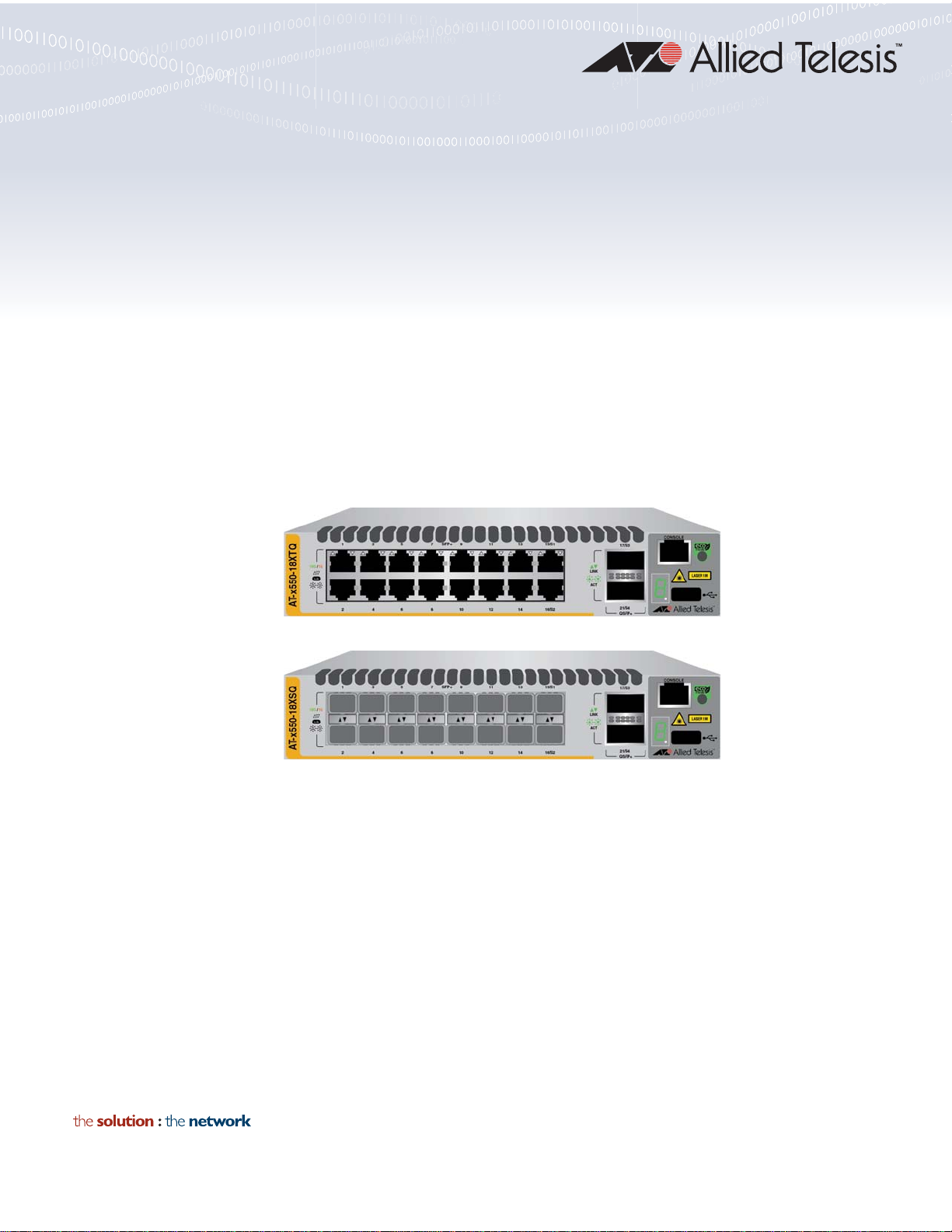
The front panels of the x550 Series switches are shown in Figure 1.
Figure 1. Front Panels of the AT-x550-18XTQ and AT-x550-18XSQ
The rear panel of the switches is shown in Figure 2 on page 17.
Switches
16
Page 17
x550 Series Installation Guide for Stand-alone Switches
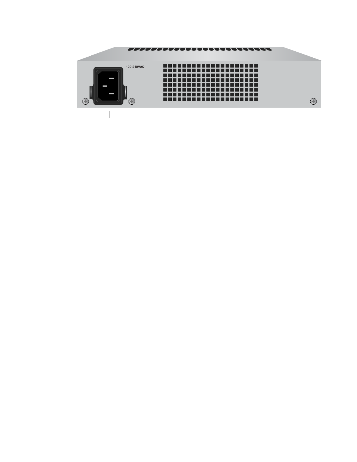
AC Power Supply Connector
Figure 2. Back Panel
17
Page 18
Chapter 1: Overview
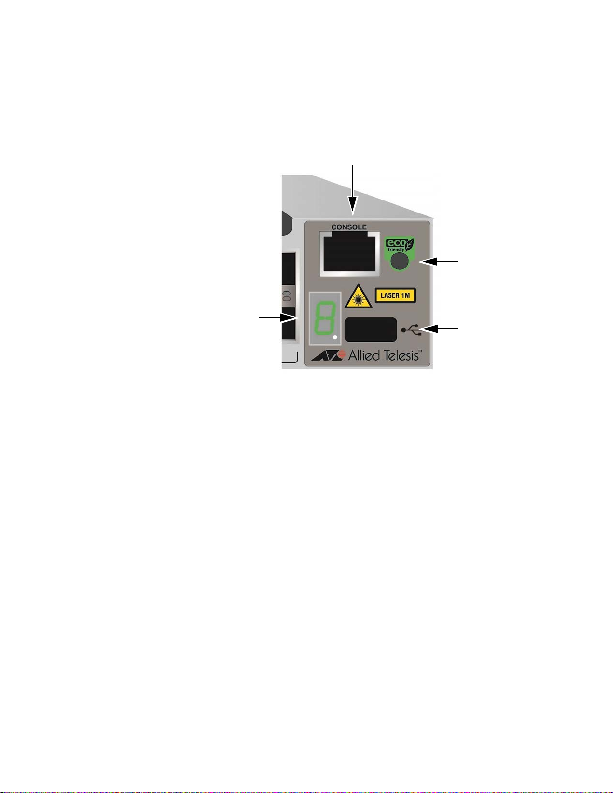
Console Management
eco-friendly
Button
Switch
Port
ID LED
USB Port
Management Panel
Figure 3 identifies the components on the management panel.
Figure 3. Management Panel
18
Page 19
Features
x550 Models Table 1 lists the basic features of the x550 Switches.
x550 Series Installation Guide for Stand-alone Switches
The Allied Telesis x550 Series switches are stackable 10 Gigabit, Layer 3
Ethernet switches. The following sections lists the features of the switches:
Table 1. Basic Features
AT-x550-18XTQ 16 0 2 Yes
AT-x550-18XSQ 0 16 2 Yes
1Gbps/10Gbps
Twisted Pair
Ports
1Gbps and
Model
Additional information is listed here:
The 40Gbps QSFP+ slots can be used as either regular networking
ports or stacking ports with the VCStack feature.
When used as regular networking ports the 40Gbps QSFP+ slots
support 40Gbps transceivers or breakout cables, which convert the
slots into four 10Gbps ports.
The switches come with one pre-installed power supply. It is not
field-replaceable.
The sixteen twisted pair ports on the AT-x550-18XTQ Switch have these
features:
1Gbps or 10Gbps operation
10Gbps
Twisted Pair
Ports
1Gbps SFP
and 10Gbps
SFP+
Transceiver
Slots
40Gbps
QSFP+
Transceiver
Slots
VCStack
1Gbps SFP or
10Gbps SFP+
Transceiver Slots
100 meters (328 feet) maximum operating distance per port
Auto-Negotiation for speed
Full-duplex mode only
Port Link/Activity (L/A) LEDs
The sixteen 1Gbps/10Gbps transceiver slots in the AT-x550-18XSQ
Switch support the following types of transceivers:
1Gbps SX/LX SFP transceivers
10Gbps SR/LR SFP+ fiber optic transceivers
10Gbps AT-SP10TW direct connect twinax cables with SFP+
transceiver-style connectors
19
Page 20

Chapter 1: Overview
Note
Additional information about the transceiver slots is given here:
They do not support 100Mbps transceivers.
They support full-duplex mode only.
SFP or SFP+ transceivers must be purchased separately. For a list of
supported transceivers, refer to the AT-x550-18XSQ data sheet on the
Allied Telesis web site.
40Gbps QSFP+
Transceiver Slots
The two QSFP+ transceiver slots support the following types of
transceivers:
AT-QSFPSR4 transceiver - 150m using multi-mode fiber optic
cable
AT-QSFPLR4 transceiver - 10k with single-mode fiber optic cable
AT-QSFP1CU and AT-QSFP3CU direct connect cables in lengths
of 1 and 3 meters, respectively
AT-QSFP-4SFP10G-3CU and AT-QSFP-4SFP10G-5CU breakout
cables in lengths of 3 and 5 meters, respectively
The QSFP+ slots are initially configured as stacking slots for the
VCStack feature. If you plan to use the switch as a stand-alone unit,
you can use the slots with transceivers as regular networking ports
by disabling the VCStack feature. The instructions are provided in
Chapter 6, “Configuring the Switch for Stand-alone Operations” on
page 85.
QSFP+ transceivers must be purchased separately. For a list of supported
transceivers, refer to the x550 product sheet on the Allied Telesis web site.
For instructions on the VCStack feature, refer to the x550 Series
Installation Guide for Virtual Chassis Stacking.
LEDs Here are the port LEDs:
Link/activity LEDs for the twisted pair ports on the AT-x550-18XTQ
Switch
Link/activity LEDs for the SFP and SFP+ transceiver slots on the
AT-x550-18XSQ Switch
Link/activity LEDs for the QSFP+ transceiver slots
Stack ID number LED
eco-friendly button turns off the LEDs to conserve electricity
20
Page 21

x550 Series Installation Guide for Stand-alone Switches
Installation
Options
Management
Software and
Interfaces
Management
Methods
Here are the installation options for the switches:
Desk or tabletop
19-inch equipment rack
Wooden or concrete wall
Here are the management software and interfaces:
AlliedWare Plus Management Software
Command line interface
Web browser interface
Here are the methods for managing the switches:
Local management through the Console port
Remote Telnet or Secure Shell management
Remote HTTP or HTTPS web browser management
SNMPv1, v2c, and v3
21
Page 22

Chapter 1: Overview
Note
1Gbps/10Gbps Twisted Pair Ports
The specifications of the sixteen twisted pair ports on the AT-x550-18XTQ
Switch are listed in Table 2.
Table 2. Twisted Pair Ports on the AT-x550-18XTQ Switch
State Description
Port Speed 1Gbps or 10Gbps
Duplex Mode Full-duplex only
Cabling 1Gbps - Standard TIA/EIA 568-B-
You can set port speed with AutoNegotiation or manually. The default is
Auto-Negotiation.
compliant Category 6 shielded cabling or
better.
10Gbps -Standard TIA/EIA 568-Ccompliant Category 6a shielded cabling or
better.
Maximum Distance 100 meters (328 feet)
Connector 8-pin RJ-45
The ports must be set to Auto-Negotiation to function at 1000 Mbps
and are not compatible with devices that are not IEEE 802.3u
compliant.
Refer to Table 16 on page 116 for the port pinouts of the twisted pair
ports.
22
Page 23

SFP+ Transceiver Slots
The sixteen SFP+ transceiver slots on the AT-x550-18XSQ Switch suppo rt
the following types of 1Gbps SFP or 10Gbps SFP+ transceivers:
1Gbps SX/LX SFP transceivers
10Gbps SR/LR fiber optic transceivers
10Gbps AT-SP10TW direct connect twinax cables with SFP+
Additional information about the SFP+ transceiver slots is listed here:
They do not support 100Mbps-FX transceivers.
They support full-duplex mode only.
You can set the port speeds with Auto-Negotiation or manually.
x550 Series Installation Guide for Stand-alone Switches
transceiver-style connectors
The default is Auto-Negotiation.
SFP or SFP+ transceivers must be purchased separately. For a list of
supported transceivers, refer to the x550 Series product sheet on the
Allied Telesis web site.
23
Page 24
Chapter 1: Overview
Note
QSFP+ Transceiver Slots
The switches have two QSFP+ transceiver slots that support the following
types of 40Gbps transceivers:
AT-QSFPSR4 transceiver - requires 12-strand OM4 fiber optic
cable and has a maximum operating distance of 150m (492 ft).
AT-QSFPLR4 transceiver - requires single-mode fiber optic cable
and has an operating range of 2m (6.6 ft) to 10km (6.2 mi).
AT-QSFP1CU and AT-QSFP3CU direct connect cables in lengths
of 1 and 3 meters, respectively
AT-QSFP-4SFP10G-3CU and AT-QSFP-4SFP10G-5CU breakout
cables in lengths of 3 and 5 meters, respectively
You can use QSFP+ transceivers as standard networking ports or as
stacking ports for the VCStack feature.
The QSFP+ transceiver slots are initially configured as stacking
slots for the VCStack feature. You have to disable the VCStack
feature to use the transceiver slots as regular networking ports. For
instructions, refer to Chapter 6, “Configuring the Switch for Standalone Operations” on page 85. For instructions on how to install the
switches in a VCStack, refer to the x550 Series Installation Guide for
Virtual Chassis Stacking.
For a list of supported QSFP+ transceivers, refer to the x550 Series data
sheet on the Allied Telesis web site.
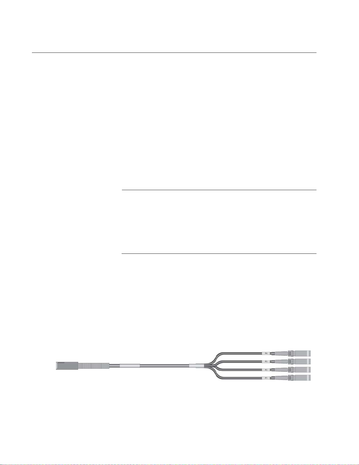
When the switch is operating as a stand-alone device and the VCStack
feature is disabled, the QSFP+ transceiver slots support the AT-QSFP4SFP10G-3CU and AT-QSFP-4SFP10G-5CU breakout cables. Refer to
Figure 4. A breakout cable converts a QSFP+ transceiver slot from one
40Gbps port to four 10Gbps ports. You have to disable the VCStack
feature on the switch to use the QSFP+ transceiver slots with breakout
cables.
Figure 4. QSFP+ to SFP+ Breakout Cable
The QSFP+ slots are numbered 17 and 21 on the front panel. Here are the
guidelines to port numbering:
24
Page 25

x550 Series Installation Guide for Stand-alone Switches
A QSFP+ transceiver in slot 17 has the port number 17.
A QSFP+ transceiver in slot 21 has the port number 21.
The four 10Gbps transceivers on a breakout cable in slot 17 have
the port numbers 17, 18, 19, and 20.
The four 10Gbps transceivers on a breakout cable in slot 21 have
the port numbers 21, 22, 23, and 24.
25
Page 26

Chapter 1: Overview
Note
eco-friendly Button
The eco-friendly button on the front panel of the switch is used to toggle
the port LEDs on or off. You might turn off the LEDs to conserve electricity
when you are not monitoring the device. You can also toggle the LEDs
with the ECOFRIENDLY LED and NO ECOFRIENDLY LED commands in
the Global Configuration mode of the command line interface of the
AlliedWare Plus management software. The switch is said to be operating
in a low power mode when the LEDs are turned off.
Operating the switch in the low power mode with the LEDs turned off does
not interfere with the network operations of the device.
The management software on the switch has a command that blinks the
LEDs so that you can quickly and easily identify a specific unit among the
devices in an equipment rack. It is the FINDME command. The command
works on the switch even if you turned off the LEDs with the eco-friendly
button or NO ECOFRIENDLY LED command.
The Switch ID LED is always on, but it displays different information
depending on whether the LEDs are on or off. When the LEDs are on, the
ID LED displays the ID number of the switch. When the switch is operating
in the low power mode with the LEDs off, the ID LED indicates whether the
switch is a stand-alone unit or the master or member switch of a VCStack,
as detailed in Figure 10 on page 33.
Before checking or troubleshooting the network connections to the
ports on the switch, you should always check to be sure that the
LEDs are on by either pressing the eco-friendly button or issuing the
ECOFRIENDLY LED and NO ECOFRIENDLY LED commands in
the Global Configuration mode of the command line interface.
26
Page 27

VCStack Feature
Note
x550 Series Installation Guide for Stand-alone Switches
You can use the switches as stand-alone units or join multiple units
together with the QSFP+ transceiver slots and the VCStack feature. The
switches of a VCStack act as a single virtual unit. They synchronize their
actions so that switching operations, like spanning tree protocols, virtual
LANs, and static port trunks, span across all of the units and ports. Two
advantages of stacks are listed here:
You can manage multiple units simultaneously, which can simplify
network management.
You have more flexibility in how you configure some of the
features. For instance, a static port trunk on a stand-alone switch
can consist of ports from the same switch. In contrast, a static trunk
on a stack can have ports from different switches in the same
stack.
This guide explains how to install the devices as stand-alone units.
For instructions on how to install the switches in a VCStack, refer to
the x550 Series Installation Guide for Virtual Chassis Stacking.
27
Page 28
Chapter 1: Overview
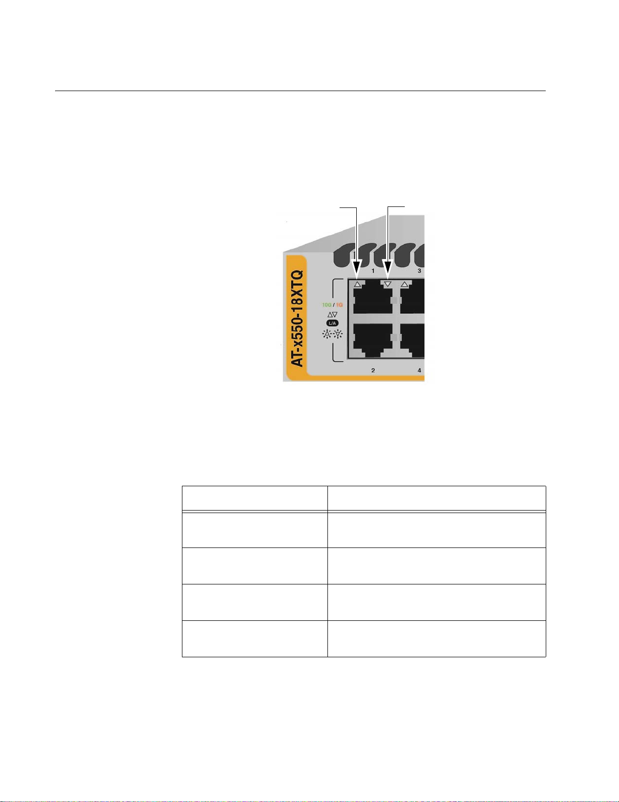
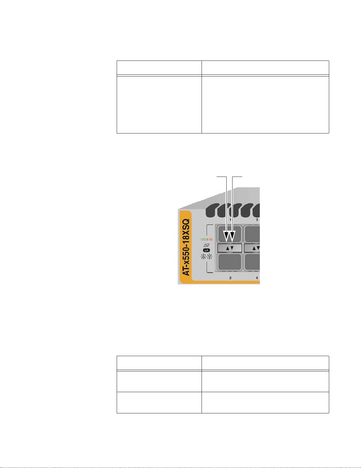
Top Port LED Bottom Port LED
LEDs
The LEDs are described in the following sections.
LEDs for the
1Gbps/10Gbps
Twisted Pair
Ports
The 1Gbps/10Gbps twisted pair ports on the AT-x550-18XTQ Switch have
one LED that displays link and activity information. The LED is shown in
Figure 5.
Figure 5. Link and Activity LEDs for the 1Gbps/10Gbps Ports on the AT-
x550-18XTQ, Switch
The states of the link and activity LEDs are described in Table 3.
Table 3. Link and Activity LEDs on the 1Gbps/10Gbps Ports on the AT-
x550-18XTQ Switch
28
State Description
Solid Green The port has established a 10Gbps link to
a network device.
Flashing Green The port is transmitting or receiving data
at 10Gbps.
Solid Amber The port has established a 1Gbps link to a
network device.
Flashing Amber The port is transmitting or receiving data
at 1Gbps.
Page 29
x550 Series Installation Guide for Stand-alone Switches
Top Transceiver Slot LED Bottom Transceiver Slot LED
Table 3. Link and Activity LEDs on the 1Gbps/10Gbps Ports on the AT-
x550-18XTQ Switch (Continued)
State Description
Off Possible causes of this state are listed
here:
- The port has not established a link with
another network device.
- The LEDs are turned off. To turn on the
LEDs, use the eco-friendly button.
LEDs for the
1Gbps SFP and
10Gbps SFP+
Transceiver Slots
The 1Gbps SFP and 10Gbps SFP+ transceiver slots on the AT-x55018XSQ Switch have one LED. The LEDs are located between the slots.
Refer to Figure 6.
Figure 6. Link and Activity LEDs for the 1Gbps SFP and 10Gbps Slot+
Slots on the AT-x550-18XSQ Switch
The LED displays link status and activity. The possible LED states are
described in Table 4.
Table 4. Link and Activity Status LEDs on the 1Gbps and 10Gbps Ports o n
the AT-x550-18XTQ Switch
State Description
Solid Green The transceiver has established a 10Gbps
link to a network device.
Flashing Green The transceiver is transmitting or receiving
data in 10Gbps.
29
Page 30
Chapter 1: Overview
Top Transceiver Slot LED Bottom Transceiver Slot LED
Table 4. Link and Activity Status LEDs on the 1Gbps and 10Gbps Ports o n
the AT-x550-18XTQ Switch (Continued)
State Description
Solid Amber The transceiver has established a 1Gbps
link to a network device.
Flashing Amber The transceiver is transmitting or receiving
data in 1Gbps.
Off Possible causes of this state are listed
here:
- The slot is empty.
- The transceiver has not established a
link to a network device.
- The LEDs are turned off. To turn on the
LEDs, use the eco-friendly button.
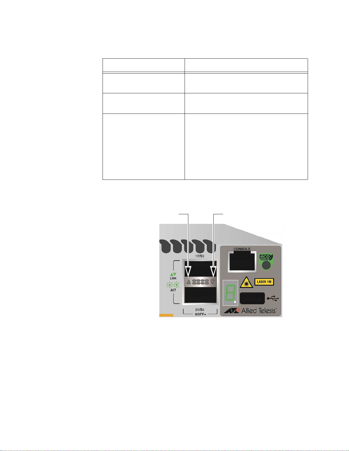
LEDs for the
40Gbps QSFP+
The 40Gbps QSFP+ transceiver slots on the switch have one LED. The
LEDs are located between the slots. Refer to Figure 7.
Transceiver Slots
Figure 7. LEDs for the 40Gbps QSFP+ Slots
The LED displays link and activity status. The LED states when the slots
have QSFP+ transceivers are described in Table 5 on page 31.
30
Page 31

x550 Series Installation Guide for Stand-alone Switches
Table 5. Link and Activity Status LEDs for the 40Gbps QSFP+ Transceiver
Slots with QSFP+ Transceivers
State Description
Solid Green The transceiver has established a 40Gbps
link to a network device.
Flashing Green The transceiver is transmitting or receiving
data.
Off Possible causes of this state are listed
here:
- The slot is empty.
- The transceiver has not established a
link to a network device.
- The LEDs are turned off. To turn on the
LEDs, use the eco-friendly button.
The L:ED states when the QSFP+ slots contain breakout cables are
described in Table 6.
Table 6. Link and Activity Status LEDs for the 40Gbps QSFP+ Transceiver
Slots with Breakout Cables
State Description
Solid Green At least one of the four ports on the
breakout cable has established a 10Gbps
link to a network device.
Flashing Green At least one of the four ports on the
breakout cable is sending or receiving
data.
Off Possible causes of this state are listed
here:
- The slot is empty.
- None of the ports on the breakout cable
have established a link to a network
device.
- The LEDs are turned off. To turn on the
LEDs, use the eco-friendly button.
31
Page 32

Chapter 1: Overview
Switch ID LED
The switch is booting up.
The switch has encountered a fault condition.
The switch is operating as a stand-alone unit, with the ID
number 0.
The switch has an ID number of 1 to 4 as part of a
The dot in the lower right corner flashes when the switch
accesses USB memory.
VCStack.
Switch ID LED The Switch ID LED, shown in Figure 8, displays the ID number of the
switch. A stand-alone switch has the ID number 0. Switches in a VCStack
have the numbers 1 to 4. Chapter 5, “Powering On the Switch” on page 77
has the procedure for verifying and, if necessary, changing the ID number
of the switch.
The states of the LED when the switch is not operating in the low power
mode are shown in Figure 9.
Figure 8. Switch ID LED
32
Figure 9. Switch ID LED
The switch displays the letter “F” for fault on the ID LED if it detects one of
the following problems:
A cooling fan has failed.
Page 33

x550 Series Installation Guide for Stand-alone Switches
Note
The switch is the master switch of a VCStack.
The switch is operating as a stand-alone unit.
The switch is a member switch of a VCStack.
The internal temperature of the switch has exceeded the normal
operating range and the switch may shut down.
You can use the SHOW SYSTEM ENVIRONMENT command in the
command line interface to identify the source of the problem.
The states of the LED when the switch is operating in the low power mode
are shown in Figure 10.
Figure 10. Switch ID LEDs in Low Power Mode
33
Page 34

Chapter 1: Overview
USB Port
The management panel has a USB port. You may use the port to store
configuration files on flash drives or to restore configuration files to
switches whose settings have been lost or corrupted, or to quickly
configure replacement units. You may also use the port and flash drives to
update the management firmware on the switch.
The port is USB2.0 compatible.
34
Page 35

Console Port
Note
x550 Series Installation Guide for Stand-alone Switches
The Console port is an RS232 serial management port. You use the port
to access the AlliedWare Plus management software on the switch to
configure the feature settings or monitor status or statistics. This type of
management is commonly referred to as local management because you
have to be at the physical location of the switch and use the management
cable included with the unit. The switch does not have to have an IP
address for local management.
To establish a local management session with the switch, you use the
provided management cable to connect a terminal or a personal computer
with a terminal emulation program to the Console port, which has an RJ45 style (8P8C) connector. The cable has RJ-45 style (8P8C) and DB-9
(D-sub 9-pin) connectors.
The Console port has the following settings:
Default baud rate: 9600 bps (Range is 9600 to 115200 bps)
Data bits: 8
Parity: None
Stop bits: 1
Flow control: None
These settings are for a DEC VT100 or ANSI terminal, or an
equivalent terminal emulation program.
35
Page 36

Chapter 1: Overview
Warning
Note
Power Supply
The switch comes with a pre-installed power supply. Refer to “Technical
Specifications” on page 111 for the input voltage ranges.
Power cord is used as a disconnection device. To de-energize
equipment, disconnect the power cord. E3
The power supply is not field-replaceable.
36
Page 37

Chapter 2
Beginning the Installation
The chapter contains the following sections:
“Reviewing Safety Precautions” on page 38
“Choosing a Site for the Switch” on page 42
“Unpacking the Switch” on page 43
37
Page 38

Chapter 2: Beginning the Installation
Note
Warning
Warning
Warning
Warning
Warning
Warning
Reviewing Safety Precautions
Please review the following safety precautions before beginning the
installation procedure.
Safety statements that have the symbol are translated into
multiple languages in the T ranslated Safety S t atements document at
www.alliedtelesis.com/support.
Class 1 Laser product. L1
Laser Radiation.
Class 1M Laser product.
Do not stare into the laser beam. L2
Do not look directly at the fiber optic ends or inspect the cable ends
with an optical lens. L6
To prevent electric shock, do not remove the cover. No userserviceable parts inside. This unit contains hazardous voltages and
should only be opened by a trained and qualified technician. To
avoid the possibility of electric shock, disconnect electric power to
the product before connecting or disconnecting the LAN cables.
E1
Do not work on equipment or cables during periods of lightning
activity. E2
38
Page 39

x550 Series Installation Guide for Stand-alone Switches
Warning
Warning
Note
Caution
Warning
Note
Warning
Caution
Power cord is used as a disconnection device. To de-energize
equipment, disconnect the power cord. E3
Class I Equipment. This equipment must be earthed. The power
plug must be connected to a properly wired earth ground socket
outlet. An improperly wired socket outlet could place hazardous
voltages on accessible metal parts. E4
Pluggable Equipment. The socket outlet shall be installed near the
equipment and shall be easily accessible. E5
Air vents must not be blocked and must have free access to the
room ambient air for cooling. E6
Operating Temperatures. This product is designed for a maximum
ambient temperature of 45° degrees C. E52
All Countries: Install product in accordance with local and National
Electrical Codes. E8
Only trained and qualified personnel are allowed to install or replace
this equipment. E14
Circuit Overloading: Consideration should be given to the
connection of the equipment to the supply circuit and the effect that
overloading of circuits might have on overcurrent protection and
supply wiring. Appropriate consideration of equipment nameplate
ratings should be used when addressing this concern. E21
39
Page 40

Chapter 2: Beginning the Installation
Caution
Warning
Warning
Note
Warning
Note
Risk of explosion if battery is replaced by an incorrect type. Replace
only with the same or equivalent type recommended by the
manufacturer. Dispose of used batteries according to the
manufacturer’s instructions.
Attention: Le remplacement de la batterie par une batterie de type
incorrect peut provoquer un danger d’explosion. La remplacer
uniquement par une batterie du même type ou de type équivalent
recommandée par le constructeur. Les batteries doivent être
éliminées conformément aux instructions du constructeur. E22
Mounting of the equipment in the rack should be such that a
hazardous condition is not created due to uneven mechanical
loading. E25
The chassis may be heavy and awkward to lift. Allied Telesis
recommends that you get assistance when mounting the chassis in
an equipment rack. E28
Use dedicated power circuits or power conditioners to supply
reliable electrical power to the device. E27
This unit might have more than one power cord. To reduce the risk
of electric shock, disconnect all power cords before servicing the
unit. E30
If installed in a closed or multi-unit rack assembly, the operating
ambient temperature of the rack environment may be greater than
the room ambient temperature. Therefore, consideration should be
given to installing the equipment in an environment compatible with
the manufacturer’s maximum rated ambient temperature (Tmra).
E35
40
Page 41

x550 Series Installation Guide for Stand-alone Switches
Caution
Warning
Warning
Caution
Warning
Caution
Warning
Installation of the equipment in a rack should be such that the
amount of air flow required for safe operation of the equipment is not
compromised. E36
Reliable earthing of rack-mounted equipment should be maintained.
Particular attention should be given to supply connections other than
direct connections to the branch circuits (e.g., use of power strips).
E37
This product may have multiple AC power cords installed. To deenergize this equipment, disconnect all power cords from the device.
E41
An Energy Hazard exists inside this equipment. Do not insert hands
or tools into open chassis slots or plugs. E44
This equipment shall be installed in a Restricted Access location.
E45
The unit does not contain serviceable components. Please return
damaged units for servicing. E42
The temperature of an operational SFP or SFP+ transceiver may
exceed 70° C (158° F). Exercise caution when removing or handling
a transceiver with unprotected hands. E43
41
Page 42

Chapter 2: Beginning the Installation
Warning
Choosing a Site for the Switch
Observe these requirements when planning the installation of the switch.
If you plan to install the switch in an equipment rack, check that the
rack is safely secured so that it will not tip over. Devices in a rack
should be installed starting at the bottom, with the heavier devices
near the bottom of the rack.
If you plan to install the switch on a table, check that the table is
level and stable.
The power outlet should be located near the switch and be easily
accessible.
The site should allow for easy access to the ports on the front of
the switch, so that you can easily connect and disconnect cables,
and view the port LEDs.
The site should allow for adequate air flow around the unit and
through the cooling vents on the front and rear panels. (The
ventilation direction is from front to back.)
The site should not expose the switch to moisture or water.
The site should be a dust-free environment.
The site should include dedicated power circuits or power
conditioners to supply reliable electrical power to the network
devices.
Do not install the switch in a wiring or utility box because it might
overheat and fail from inadequate airflow.
Switches should not be stacked on a table or desktop. They could
present a physical safety hazard if you need to move or replace
switches. E91
42
Page 43

Unpacking the Switch
Note
C
A
B
Figure 11 shows the shipping box for the switch.
x550 Series Installation Guide for Stand-alone Switches
Figure 11. AT-x550-18XTQ or AT-x550-18XSQ Switch Shipping Box
The items in the box are listed here:
A - Protective bag
B - AT-x550 Switch
C - Accessory kit
You should retain the original packaging material in case you need
to return the unit to Allied Telesis.
43
Page 44

Chapter 2: Beginning the Installation
Four AT-RKMT-J24 wallmounting brackets
One 2m (6.6 ft) local management
cable with RJ-45 (8P8C) and DB-9 (Dsub 9-pin) connectors.
Sixteen screws for attaching the ATRKMT-J24 wall brackets to the
switch.
Length: 6.0mm (0.2 in.)
Diameter: 4.0mm (0.2 in.)
One regional AC power cord
Four anchors for concrete walls:
Length: 29.6mm (1.2 in.)
Diameter: 6.0mm (0.2 in.)
Four screws for wood or concrete
walls:
Length: 32mm (1.3 in.)
Diameter: 4mm (0.2 in.)
Power cord retaining clip
Figure 12 here and Figure 13 on page 45 list the items in the accessory kit
included with the switch. Contact your Allied Telesis sales representative
for assistance if any item is missing or damaged.
Figure 12. Accessory Kit
44
Page 45

x550 Series Installation Guide for Stand-alone Switches
Two AT-RKMT-J14 equipment
rack brackets
Two handles for the AT-RKMTJ14 equipment rack brackets
Four screws for attaching the handles
to the AT-RKMT-J14 equipment rack
brackets:
Length: 6.0mm (0.2 in.)
Diameter: 3.0mm (0.1 in.)
Figure 13. Accessory Kit (Continued)
45
Page 46

Chapter 2: Beginning the Installation
46
Page 47

Chapter 3
Installing the Switch on a Table or in an Equipment Rack
This chapter contains the instructions for installing the switch on a table or
in an equipment rack. The procedures in this chapter are listed here:
“Installing the Switch on a Table or Desktop” on page 48
“Overview of Installing the Switch in an Equipment Rack” on page 49
“Installing the Switch in an Equipment Rack with the AT-RKMT-J14
Brackets” on page 51
“Installing the Switch in an Equipment Rack with the AT-RKMT-J15
Bracket” on page 56
47
Page 48
Chapter 3: Installing the Switch on a Table or in an Equipment Rack
Note
Warning
Installing the Switch on a Table or Desktop
This section contains the procedure for installing the switch on a table.
The rubber feet on the bottom of the chassis should be left on for
table installation.
Switches should not be stacked on a table or desktop. They could
present a physical safety hazard if you need to move or replace
switches. E91
To install the chassis on a table, perform the following procedure:
1. Review the procedure in Chapter 2, “Choosing a Site for the Switch”
on page 42to verify that the selected site is suitable for the unit.
2. Check to be sure that the table is strong enough to support the weight
of the switch.
3. Lift the chassis onto the table.
4. Check to be sure that all of the appropriate components are included
in the shipping container. Refer to “Unpacking the Switch” on page 43.
After placing the switch on the table or desktop, go to Chapter 5,
“Powering On the Switch” on page 77.
48
Page 49

x550 Series Installation Guide for Stand-alone Switches
Overview of Installing the Switch in an Equipment Rack
You can install the switch in a 19-inch equipment rack two ways. One way
is with the AT-RKMT-J14 brackets that come with the switch. Refer to
Figure 14.
Figure 14. AT-RKMT-J14 Brackets and Switch
For installation instructions, refer to “Installing the Switch in an Equipment
Rack with the AT-RKMT-J14 Brackets” on page 51.
You can also install the switch in an equipment rack with the optional ATRKMT-J15 bracket. Refer to Figure 15.
Figure 15. AT-RKMT-J15 Bracket
49
Page 50

Chapter 3: Installing the Switch on a Table or in an Equipment Rack
Note
The bracket lets you install two switches side-by-side. Refer to Figure 16.
Figure 16. AT-RKMT-J15 Bracket with Switches
The AT-RKMT-J15 Bracket is purchased separately.
For installation instructions refer to “Installing the Switch in an Equipment
Rack with the AT-RKMT-J15 Bracket” on page 56
50
Page 51

x550 Series Installation Guide for Stand-alone Switches
Bracket Holes
Installing the Switch in an Equipment Rack with the AT-RKMT-J14 Brackets
This section contains the procedure for installing the switch in a standard
19-inch equipment rack, with the AT-RKMT-J14 Brackets included with the
switch.
Required Items
for the AT-
RKMT-J14
Brackets
Switch
Orientations in
the Equipment
Rack
The following items are required to install the switch in an equipment rack
with the AT-RKMT-J14 Brackets:
Two AT-RKMT-J14 equipment rack brackets (included with the
switch)
Eight M4x6mm bracket screws (included with the switch)
Four M3x6mm screws (included with the switch)
Two bracket handles (included with the switch)
Cross-head screwdriver (not provided)
Four standard equipment rack screws (not provided)
The switch has two sets of four screw holes on the left and right sides, for
attaching the AT-RKMT-J14 Brackets. Refer to Figure 17.
Figure 17. Bracket Holes
The brackets also have two sets of four holes. Refer to Figure 18 on page
52.
51
Page 52

Chapter 3: Installing the Switch on a Table or in an Equipment Rack
Set 1 Set 2
Figure 18. AT-RKMT-J14 Bracket Holes
You can use the different sets of holes on the switch and brackets to install
the switch in the equipment rack in a variety of orientations. You can install
it with the front panel flush with, extending in front of, or recessed behind
the front of the equipment rack. The illustrations in Figure 19 show the
switch orientations with the front panel facing the front of the equipment
rack.
52
Figure 19. Switch Orientations with the Front Panel Facing the Front of the
Equipment Rack
Page 53

x550 Series Installation Guide for Stand-alone Switches
Caution
You can also orient the switch with the rear panel facing the front of the
equipment rack. Refer to Figure 20 on page 53.
Installing the
Switch with the
AT-RKMT-J14
Brackets
Figure 20. Switch Orientations with the Rear Panel Facing the Front of the
Equipment Rack
If you have not chosen an orientation for the switch in the e quipment rack,
review “Switch Orientations in the Equipment Rack” on page 51.
Please review the installation guidelines in “Choosing a Site for the Switch”
on page 42 before installing the switch in an equipment rack.
The chassis may be heavy and awkward to lift. Allied Telesis
recommends that you get assistance when mounting the chassis in
an equipment rack. E28
To install the switch in a 19-inch equipment rack with the AT-RKMT-J14
Brackets, perform the following procedure:
1. Attach the two handles to the AT-RKMT-J14 Brackets using the four
M3x6mm screws included with the switch. Refer to Figure 21 on page
54.
53
Page 54

Chapter 3: Installing the Switch on a Table or in an Equipment Rack
Figure 21. Attaching the Handles to the AT-RKMT-J14 Brackets
2. Place the switch on a level, secure surface.
3. Attach the two brackets to the sides of the switch in the selected
position, using the eight M4x6mm screws included with the unit. The
illustration in Figure 22 shows the installation of the brackets such that
the front panel of the switch is even with the front of the equipment
rack.
54
Figure 22. Attaching the AT-RKMT-J14 Brackets to the Switch
Page 55

x550 Series Installation Guide for Stand-alone Switches
4. Have another person hold the switch in the equipment rack at the
desired location while you secure it using four standard equipment
rack screws (not provided). Refer to Figure 23.
Figure 23. Installing the Switch in an Equipment Rack
5. Go to Chapter 5, “Powering On the Switch” on page 77.
55
Page 56

Chapter 3: Installing the Switch on a Table or in an Equipment Rack
Installing the Switch in an Equipment Rack with the AT-RKMT-J15 Bracket
This section contains the procedure for installing the switch in a standard
19-inch equipment rack, with the optional AT-RKMT-J15 Bracket.
Required Items
for the AT-
RKMT-J15
Bracket
Installing the
Switch with the
AT-RKMT-J15
Bracket
The following items are required to install the switch in an equipment rack
with the AT-RKMT-J15 Bracket:
One AT-RKMT-J15 equipment rack bracket (sold separately)
Four M4x6mm bracket screws (included with the switch)
Cross-head screwdriver (not provided)
Flat-head screwdriver (not provided)
Four standard equipment rack screws (not provided)
To install the switch in a 19-inch equipment rack with the AT-RKMT-J15
Bracket, perform the following procedure:
1. Have another person hold the AT-RKMT-J15 Bracket at the desired
location in the equipment rack while you secure it using four standard
equipment rack screws (not provided). Refer to Figure 24.
56
Figure 24. Installing the AT-RKMT-J15 Bracket in the Equipment Rack
Page 57

x550 Series Installation Guide for Stand-alone Switches
2. Loosen the two thumbscrews on the front of the bracket. Refer to
Figure 25.
Figure 25. Loosening the Two Thumbscrews on the Front of the AT-
RKMT-J15 Bracket
3. Slide out the bracket tray. Refer to Figure 26.
Figure 26. Sliding Out the Tray from the AT-RKMT-J15
57
Page 58

Chapter 3: Installing the Switch on a Table or in an Equipment Rack
Note
Steps 4 to 6 remove the plastic feet from the bottom of the switch.
You must remove the plastic feet to install the switch in the ATRKMT-J15 Bracket.
4. Place the switch upside-down on a table.
5. Use a small flat-head screwdriver to pry the four plastic feet from the
bottom of the switch. Refer to Figure 27.
Figure 27. Removing the Plastic Feet from the Bottom Panel of the Switch
6. Turn the switch over so that it is right-side up.
7. Place the switch in the left or right side of the bracket, with its front
panel facing the front of the bracket. If you are installing only one
switch, you may install it on either the left or right side. Refer to Figure
28 on page 59.
58
Page 59

x550 Series Installation Guide for Stand-alone Switches
Figure 28. Placing a Switch in the AT-RKMT-J15 Bracket
8. Install two M4x6mm screws included with the switch to secure the
switch to the bracket. Refer to Figure 29.
Figure 29. Securing the Switch to the AT-RKMT-J15 Bracket
59
Page 60

Chapter 3: Installing the Switch on a Table or in an Equipment Rack
9. To install a second switch in the bracket, repeat steps 4 to 8.
10. Slide in the bracket tray. Refer to Figure 30.
Figure 30. Sliding in the Bracket Tray
11. Tighten the two thumbscrews to secure the tray to the bracket. Refer
to Figure 31 on page 61.
60
Page 61

x550 Series Installation Guide for Stand-alone Switches
Figure 31. Tightening the Two Thumbscrews on the AT-RKMT-J15
Bracket
12. Go to Chapter 5, “Powering On the Switch” on page 77.
61
Page 62

Chapter 3: Installing the Switch on a Table or in an Equipment Rack
62
Page 63

Chapter 4
Installing the Switch on a Wall
The procedures in this chapter are listed here:
“Switch Orientations on a Wall” on page 64
“Installation Guidelines” on page 65
“Plywood Base for a Wall with Wooden Studs” on page 67
“Installing a Plywood Base” on page 69
“Installing the Switch on a Plywood Base” on page 70
“Installing the Switch on a Concrete Wall” on page 73
63
Page 64

Chapter 4: Installing the Switch on a Wall
Front Panel Front Panel
Switch Orientations on a Wall
You can install the switch on a wall with the front panel on the left or right,
as shown in Figure 32. Do not install it with the front panel on the top or
bottom.
Figure 32. Positions of the Switch on the Wall
64
Page 65

Installation Guidelines
Warning
Warning
Here are the guidelines to installing the switch on a wall:
You may install the switch on a wall that has wooden studs or on a
If you are installing the switch on a wall with wooden studs, you
You should not install the switch on a wall that has metal studs.
You should not install the switch only on sheetrock or similar
x550 Series Installation Guide for Stand-alone Switches
concrete wall.
should use a plywood base to support the switch. For more
information, refer to “Plywood Base for a Wall with Wooden Studs”
on page 67. A plywood base is not required for a concrete wall.
Metal studs may not be strong enough to safely support the device.
material. Sheetrock is not strong enough to safely support the
device.
Tools and
Material
The device is heavy. Always ask for assistance before moving or
lifting it to avoid injuring yourself or damaging the equipment.
The device should be installed on the wall by a qualified building
contractor. Serious injury to yourself or others or damage to the
equipment may result if it is not properly fastened to the wall.
E105
Here are the required tools and material for installing the switch on a wall:
Four AT-BRKT-J24 wall brackets (included with the switch)
Sixteen screws (included with the switch) to attach the AT-BRKT-
J24 brackets to the switch.
Four wall screws (included with the switch)
Four anchors for a concrete wall (included with the switch)
Cross-head screwdriver (not provided)
Stud finder for a wooden wall, capable of identifying the middle of
wall studs and hot electrical wiring (not provided)
Drill and 1/4” carbide drill bit for a concrete wall (not provided)
Plywood base if you are installing the switch on a wall with wooden
studs (not provided.) Refer to “Plywood Base for a Wall with
Wooden Studs” on page 67 for illustrations.
Four screws for attaching the plywood base to the wall (not
65
Page 66

Chapter 4: Installing the Switch on a Wall
Caution
provided)
The supplied screws and anchors might not be appropriate for all
walls. A qualified building contractor should determine the hardware
requirements for your wall prior to installing the switch. E88
66
Page 67
Plywood Base for a Wall with Wooden Studs
Wall Studs
Wall
Plywood Base
If you are installing the switch on a wall that has wooden studs, Allied
Telesis recommends using a plywood base to attach the device to it. (A
plywood base is not required for a concrete wall.) Refer to Figure 33.
x550 Series Installation Guide for Stand-alone Switches
Figure 33. Switch on the Wall with a Plywood Base
The plywood base allows you to mount the switch on two wall studs. The
standard distance between two studs in a wall is 41 centimeters (16
67
Page 68

Chapter 4: Installing the Switch on a Wall
Step 1: Install the
plywood base on
the wall.
Step 2: Install the
switch on the
plywood base.
Wall
Plywood
Base
Wall Studs
inches) while the distance between the front and rear brackets on the
switch is 34.4 centimeters (13.6 inches). If you install the switch without
the base, only two brackets on the switch would be on a wall stud.
The recommended minimum dimensions of the plywood base are listed
here:
Width: 55.9 centimeters (22 inches)
Height: 35.6 centimeters (14 inches)
Thickness: 5.1 centimeters (2 inches)
The dimensions assume the wall studs are 41 centimeters (16 inches)
apart. You might need to adjust the width of the base if the distance
between the studs in your wall is different than the industry standard.
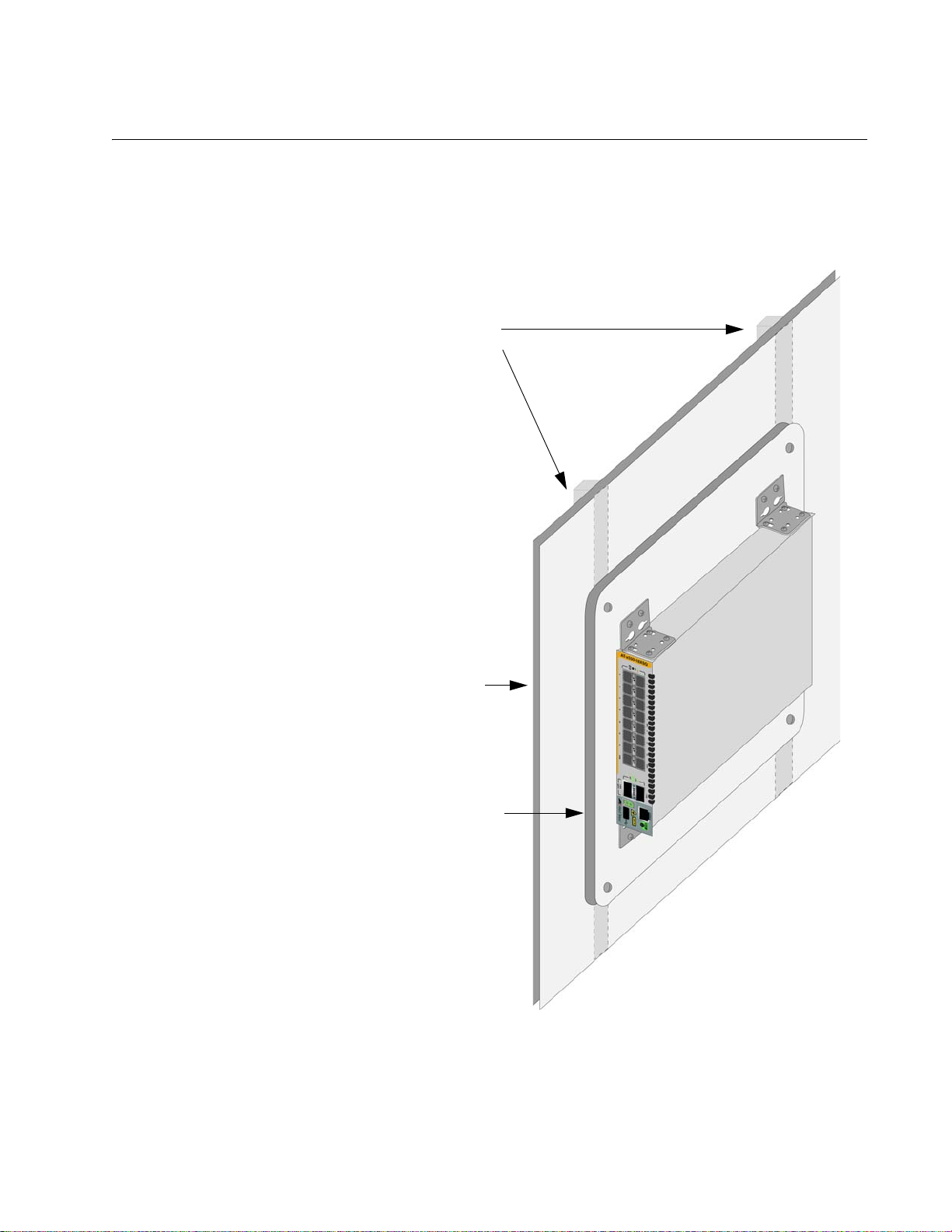
You should install the plywood base on the wall and then install the switch
on the base. Refer to Figure 34.
68
Figure 34. Steps to Installing the Switch with a Plywood Base
Page 69

Installing a Plywood Base
A plywood base is recommended when installing the switch on a wall that
has wooden studs. Refer to “Plywood Base for a Wall with Wooden Studs”
on page 67. Consult a qualified building contractor for installation
instructions for the plywood base. The installation guidelines are listed
here:
You should use a stud finder to identify the middle of studs and hot
electrical wiring in the wall.
You should attach the base to two wall studs with a minimum of
four screws.
The selected wall location for the base should provide sufficient
space from other devices or walls so that you can access the front
and back panels.
x550 Series Installation Guide for Stand-alone Switches
69
Page 70

Chapter 4: Installing the Switch on a Wall
Warning
Warning
Installing the Switch on a Plywood Base
This procedure assumes that the plywood base for the switch is already
installed on the wall. Please review “Reviewing Safety Precautions” on
page 38 and “Choosing a Site for the Switch” on page 42 before
performing this procedure. Allied Telesis recommends a minimum of two
people for this procedure.
The device is heavy. Always ask for assistance before moving or
lifting it to avoid injuring yourself or damaging the equipment.
The device should be installed on the wall by a qualified building
contractor. Serious injury to yourself or others or damage to the
equipment may result if it is not properly fastened to the wall.
E105
To install the switch on the plywood base, perform the following
procedure:
1. Place the switch in a table.
2. Install the four wall brackets to the sides of the unit, with the sixteen
M4x6mm screws included with the switch. Refer to Figure 35 on page
71.
70
Page 71

x550 Series Installation Guide for Stand-alone Switches
Figure 35. Installing the Wall Brackets
3. After attaching the brackets to the side of the switch, have another
person hold the switch on the plywood base on the wall while you
secure it with the four M4x32.3mm screws included with the switch.
Refer to Figure 36 on page 72.
Please follow these guidelines as you position the switch on the wall:
Position the switch so that the front panel is either on the left or
right. Refer to Figure 35. You may not install the switch with the
front panel facing up or down.
Leave sufficient space from other devices or walls so that you can
access the front and back panels.
71
Page 72

Chapter 4: Installing the Switch on a Wall
Figure 36. Securing the Switch to the Plywood Base
4. Go to Chapter 5, “Powering On the Switch” on page 77.
72
Page 73

Installing the Switch on a Concrete Wall
Warning
Warning
This section contains the instructions for installing the switch on a concrete
wall. Please review the information in the following sections before
performing the procedure:
“Switch Orientations on a Wall” on page 64
“Installation Guidelines” on page 65
The device is heavy. Always ask for assistance before moving or
lifting it to avoid injuring yourself or damaging the equipment.
The device should be installed on the wall by a qualified building
contractor. Serious injury to yourself or others or damage to the
equipment may result if it is not properly fastened to the wall.
E105
x550 Series Installation Guide for Stand-alone Switches
To install the switch on a concrete wall, perform the following procedure:
1. Place the switch in a table.
2. Install the four AT-BRKT-J24 wall brackets to the sides of t he unit with
the sixteen M4x6mm screws that come with the switch.
3. Have another people hold the switch on the concrete wall at the
selected location for the device while you use a pencil or pen to mark
the wall with the locations of the four screw holes in the four brackets
(one screw per bracket). Refer to Figure 37 on page 74.
Please follow these guidelines as you position the switch on the wall:
Position the switch so that the front panel is either on the left or the
right. Refer to Figure 32 on page 64. You may not install the switch
with the front panel facing up or down.
Leave sufficient space from other devices or walls so that you can
access the front and back panels.
73
Page 74

Chapter 4: Installing the Switch on a Wall
Figure 37. Marking the Locations of the Bracket Holes on a Concrete Wall
4. Place the switch on a table or desk.
5. Use a drill and 1/4” carbide drill bit to pre-drill the four holes you
marked in step 3. Please review the following guidelines:
Prior to drilling, set the drill to hammer and rotation mode. The
modes break up the concrete and clean out the hole.
Allied Telesis recommends cleaning out the holes with a brush or
compressed air.
6. Insert the four anchors into the holes.
7. Have another person hold the switch at the selected wall location while
you secure it to the wall with the four M4x32mm provided screws.
Refer to Figure 38 on page 75.
74
Page 75

x550 Series Installation Guide for Stand-alone Switches
Figure 38. Installing the Switch on a Concrete Wall
8. Go to Chapter 5, “Powering On the Switch” on page 77.
75
Page 76

Chapter 4: Installing the Switch on a Wall
76
Page 77

Chapter 5
Powering On the Switch
This chapter contains the following procedures:
“Powering On the Switch” on page 78
“Monitoring the Initialization Processes” on page 81
77
Page 78

Chapter 5: Powering On the Switch
Warning
Note
Powering On the Switch
Before powering on the switch, review the information in “Power
Specifications” on page 114 for the power specifications of the switches.
Power cord is used as a disconnection device. To de-energize
equipment, disconnect the power cord. E3
Pluggable Equipment. The socket outlet shall be installed near the
equipment and shall be easily accessible. E5
To power on the switch, perform the following procedure:
1. Install the power cord retaining clip on the AC power connector on the
rear panel of the switch. Refer to Figure 39.
78
Figure 39. Installing the Power Cord Retaining Clip
2. Connect the AC power cord to the AC power connector on the rear
panel of the switch. Refer to Figure 40 on page 79.
Page 79

x550 Series Installation Guide for Stand-alone Switches
Figure 40. Connecting the AC Power Cord
3. Lower the power cord retaining clip to secure the cord to the switch.
Refer to Figure 41.
Figure 41. Lowering the Power Cord Retaining Clip
4. Connect the power cord to an appropriate AC power source. Refer to
Figure 42 on page 80.
79
Page 80

Chapter 5: Powering On the Switch
Note
Figure 42. Connecting the Power Cord to an AC Power Source
The illustration shows a North American power cord. Your power
cord may be different.
5. Do one of the following:
To monitor the switch as it initializes the management software, go
to “Monitoring the Initialization Processes” on page 81.
Wait two minutes for the switch to initialize its management
software and then go to Chapter 6, “Configuring the Switch for
Stand-alone Operations” on page 85.
80
Page 81

Monitoring the Initialization Processes
Bootloader 6.2.1 loaded
Press <Ctrl+B> for the Boot Menu
Loading flash:x550-cap_x550-20170315-1.rel...
Verifying release... OK
Booting...
Uncompressing Linux... done, booting the kernel
Starting base/first... [ OK ]
Mounting virtual filesystems... [ OK ]
______________ ____
/\ \ / /______\
/ \ \_ __/ /| ______ |
/ \ | | / | ______ |
/ \ \ / / \ ____ /
/______/\____\ \/ /____________/
Allied Telesis Inc.
AlliedWare Plus (TM) v0.0.0
Current release filename: x550-cap_20170315-1.rel
Built: Tue Mar 14 23:31:58 UTC 2017
Mounting static filesystems... [ OK ]
Attaching to /dev/mtd0... [ OK ]
Checking flash filesystem... [ OK ]
Mounting file system... [ OK ]
Checking for last gasp debug output... [ OK ]
Checking NVS filesystem... [ OK ]
Mounting NVS filesystem... [ OK ]
Initializing random number genera tor .. . [ OK ]
Starting base/arm_sysctl... [ OK ]
Starting base/dbus... [ OK ]
It takes about two minutes for the switch to initialize its management
software programs and features, and load the default configuration. You
can monitor the bootup sequence by connecting a terminal or computer
that has a terminal emulator program to the Console port on the switch.
(The settings of the Console port are provided in “Starting a Local
Management Session” on page 87.) The switch displays the messages in
Figure 43 here to Figure 45 on page 83 on the Console port as it initializes
the management software.
x550 Series Installation Guide for Stand-alone Switches
Figure 43. Switch Initialization Messages
81
Page 82

Chapter 5: Powering On the Switch
Starting base/syslog... [ OK ]
Starting base/loopback... [ OK ]
Starting base/poe_done... [ OK ]
Starting base/sysctl... [ OK ]
Received event poefw.done
Starting base/portmapper... [ OK ]
Received event syslog.done
Starting base/modules... [ OK ]
Received event modules.done
Starting base/reboot-stability... [ OK ]
Checking system reboot stability... [ OK ]
Starting base/apteryx... [ OK ]
Starting base/crond... [ OK ]
Starting base/appmond... [ OK ]
Starting base/clockcheck... [ OK ]
Starting hardware/timeout... [ OK ]
Starting base/inet... [ OK ]
Received event apteryx.done
Starting base/alfred... [ OK ]
Starting base/kernond... [ OK ]
Starting base/plugman... [ OK ]
Starting base/apteryx-sync... [ OK ]
Starting base/openhpi... [ OK ]
Received event apteryx-sync.done
Received event board.inserted
Starting hardware/hardware-done... [ OK ]
Received event hardware.done
Starting network/startup... [ OK ]
Starting base/external-media... [ OK ]
Received event hostcfg.done
Starting network/stackd... [ OK ]
Starting network/election.timeout... [ OK ]
Received event network.enabled
Initializing HA processes:
atmfd_agentd, atmfd, hostd, auth, cntrd, epsr, hsl
imi, imiproxyd, irdpd, lacp, lldpd, loopprot, mstp
nsm, ospf6d, pdmd, pim6d, pimd, ripd, ripngd
rmon, sflowd, udldd, vrrpd, bgpd, ospfd
Figure 44. Switch Initialization Messages (Continued)
82
Page 83

x550 Series Installation Guide for Stand-alone Switches
Received event network.initialized
00:50:36 awplus-1 VCS[596]: No neighboring members found, unit may be in a
standalone configuration
Received event vcs.elected-master
Assigning Active Workload to HA processes:
00:50:36 awplus-1 VCS[596]: Startup speed can be improved by adding 'no stack
1 enable’ to configuration
00:50:36 awplus-1 VCS[596]: Member 1 (e01a.ea20.80dd) has become the Active
Master
hsl, authd, epsrd, irdpd, lacpd, loopprotd
mstpd, nsm, rmond, sflowd, vrrpd, imi, imiproxyd
Received event network.activated
Loading default configuration
Warning: flash:/default.cfg doe s no t exi st , lo ad ing fac to ry defaults.
..
done!
Received event network.configured
awplus login:
Figure 45. Switch Initialization Messages (Continued)
After the switch has initialized its management software, go to Chapter 6,
“Configuring the Switch for Stand-alone Operations” on page 85.
83
Page 84

Chapter 5: Powering On the Switch
84
Page 85

Chapter 6
Configuring the Switch for Stand-alone Operations
This chapter contains the following procedures:
“Determining the Stand-alone or Stacking Status of the Switch” on
page 86
“Starting a Local Management Session” on page 87
“Disabling the VCStack Feature” on page 89
“Configuring QSFP+ Transceiver Slot s 17 and 21 for Breakout Cables”
on page 91
“Saving Your Changes and Rebooting the Switch” on page 92
“Specifying Ports in the Command Line Interface for Stand-alone
Switches” on page 93
85
Page 86

Chapter 6: Configuring the Switch for Stand-alone Operations
Caution
Note
Determining the Stand-alone or Stacking Status of the Switch
After powering on the switch and waiting two minutes for it to initialize its
management software, examine the switch ID LED on the front panel. If
the LED is displaying the number “1” or higher, the VCStack feature is
enabled on the unit. You need to disable it to use the switch in stand-alone
mode. For instructions, start with “Starting a Local Management Session”
on page 87.
If the LED is displaying “0”, the VCStack feature is already disabled and
the switch is operating as a stand-alone unit. Do one of the following:
If you plan to use breakout cables in the QSFP+ transceiver slots,
perform “Starting a Local Management Session” on page 87 and
“Configuring QSFP+ Transceiver Slots 17 and 21 for Breakout
Cables” on page 91.
Otherwise, go to Chapter 7, “Cabling the Networking Ports” on
page 95.
You have to reset the switch to disable the VCStack feature. Some
network traffic may be lost if the device is already connected to a live
network. E89
The initial management session of the switch must be from the
Console port.
86
Page 87

Starting a Local Management Session
Note
This procedure requires a terminal or a terminal emulator program and the
management cable that comes with the switch. To start a local
management session on the switch, perform the following procedure:
1. Connect the RJ-45 connector on the management cable to the
Console port on the front panel of the switch, as shown in Figure 46.
x550 Series Installation Guide for Stand-alone Switches
Figure 46. Connecting the Management Cable to the Console Port
2. Connect the other end of the cable to an RS-232 port on a terminal or
PC with a terminal emulator program.
3. Configure the terminal or terminal emulator program as follows:
Baud rate: 9600 bps (The baud rate of the Console Port is
adjustable from 1200 to 115200 bps. The default is 9600 bps.)
Data bits: 8
Parity: None
Stop bits: 1
Flow control: None
The port settings are for a DEC VT100 or ANSI terminal, or an
equivalent terminal emulator program.
87
Page 88

Chapter 6: Configuring the Switch for Stand-alone Operations
Note
awplus>
4. Press Enter.
You are prompted for a user name and password.
5. When prompted, enter a user name and password to log on the
switch. If this is the initial management session, enter “manager” as
the user name and “friend” as the password. The user name and
password are case sensitive.
The local management session starts when the User Exec mode
prompt, shown in Figure 47. is displayed.
The User Exec mode is the first level in the command mode
interface. For complete information on the modes and commands,
refer to the Software Reference for x550 Series Switches,
AlliedWare Plus Operating System at www.alliedtelesis.com.
Figure 47. User Exec Mode Prompt
6. Do one of the following:
If you need to disable the VCStack feature, perform the procedure
in “Disabling the VCStack Feature” on page 89.
If the VCStack feature is already disabled, but you plan to use
breakout cables in the QSFP+ slots, go to “Configuring QSFP+
Transceiver Slots 17 and 21 for Breakout Cables” on page 91.
88
Page 89

Disabling the VCStack Feature
Caution
awplus> show stack
Virtual Chassis Stacking summary inf or ma tio n
ID Pending ID MAC address Priority Status Role
1 - eccd:6dd1:64a2 128 Ready Active Master
Operational Status Standalone Unit
Stack MAC address eccd:6dd1:64a2
awplus>
The following procedures explain how to disable the VCStack feature to
use the switch as a stand-alone unit.
Disabling the VCStack feature requires resetting the switch. Some
network traffic may be lost if the switch is connected to a live
network. E89
To disable the VCStack feature, perform the following procedure:
1. Start a local management session on the switch. For instructions, refer
to “Starting a Local Management Session” on page 87.
2. At the User Exec mode prompt, enter the SHOW STACK command to
display the status of the VCStack feature on the switch. Figure 48 is an
example of the command.
x550 Series Installation Guide for Stand-alone Switches
Figure 48. SHOW STACK Command
3. If the Operational Status of the switch is “Stacking Hardware
Disabled,” the VCStack feature is already disabled on the unit. You
can use the transceiver slots 17 and 21 with QSFP+ transceivers as
regular networking ports. To use the slots with breakout cables, go to
“Configuring QSFP+ Transceiver Slots 17 and 21 for Breakout Cables”
on page 91. Otherwise, go to Chapter 7, “Cabling the Networking
Ports” on page 95.
4. If the Operational Status is “Standalone Unit,” the VCStack feature is
active on the unit. (The “standalone” status means the switch is
functioning as a stack of one switch.) You must disable the feature to
use the switch as a stand-alone unit. Continue with the next step.
1. Move to the Global Configuration mode by entering the ENABLE and
CONFIGURE TERMINAL commands, as shown in Figure 49 on page
90.
89
Page 90

Chapter 6: Configuring the Switch for Stand-alone Operations
awplus> enable
awplus# configure terminal
Enter configuration commands, one per line. End with CNTL/Z
awplus#
Warning; This will disable the stacki ng ha rd wa re on mem ber -1 .
Are you sure you want to continue? (y/n):
awplus(config)#18:04:12 awplu s VC S[ 21 19] : De ac tiv at ing
Stacking Ports on stack member 1.
Figure 49. Moving to the Global Configuration Mode
2. To. disable the VCStack feature, enter the NO STACK ENABLE
command in this format:
no stack
id
The ID parameter is the ID number of the switch, displayed on the ID
LED. Replace the parameter with the number on the ID LED. For
example, if the ID number of the switch is 1, the default value, enter
the command as follows:
awplus(config)# no stack 1 enable
The confirmation prompt in Figure 50 is displayed.
enable
Figure 50. Confirmation Prompt for the NO STACK ENABLE Command
3. Type Y to disable VCStack on the switch or N to cancel the procedure.
The switch displays the message in Figure 51.
Figure 51. Disabling VCStack
4. Press the Return key to re-display the Global Configuration mode
prompt.
5. Do one of the following:
To configure P17 and P21 transceiver slots for breakout cables, go
to “Configuring QSFP+ Transceiver Slots 17 and 21 for Breakout
Cables” on page 91 and start with step 3.
Otherwise, go to “Saving Your Changes and Rebooting the Switch”
on page 92.
90
Page 91

x550 Series Installation Guide for Stand-alone Switches
Configuring QSFP+ Transceiver Slots 17 and 21 for Breakout Cables
To configure the QSFP+ transceiver slots 17 and 21 for breakout cables,
perform the following procedure:
1. Start a local management session on the switch. For instructions, refer
to “Starting a Local Management Session” on page 87.
2. Move to the Global Configuration mode by entering the ENABLE and
CONFIGURE TERMINAL commands, as shown in Figure 49 on page
90.
3. Enter the PLATFORM PORTMODE INTERFACE command to
configure one or both QSFP+ transceiver slots for breakout cables.
The format of the command is shown here:
platform portmode interface ports 10gx4|40g
The PORTS variable specifies the QSFP+ transceiver slots for the
breakout cables, which are 1.0.17 and 1.0.21 on the x550 Ethernet
Switch Series. The 10gx4 parameter configures the slots for breakout
cables while the 40g parameter configures the slots for regular QSFP+
transceivers, which is the default.
This example of the command configures QSFP+ transceiver slot 17
for a breakout cable:
awplus(config)# platform portmode interface port1.0.17
10gx4
4. After configuring the transceiver slots, go to “Saving Your Changes
and Rebooting the Switch” on page 92.
91
Page 92

Chapter 6: Configuring the Switch for Stand-alone Operations
awplus(config)# exit
awplus#
awplus# write
Building configuration ...
[OK]
awplus#
Saving Your Changes and Rebooting the Switch
After disabling the VCStack feature or configuring the 1.0.17 and 1.0.21
transceiver slots for breakout cables, you have to save your configuration
changes and reboot the switch. Changes to the status of the VCStack
feature and QSFP+ transceiver slots do not take affect until after you
reboot the unit.
To save your configuration changes and reboot the switch, perform the
following procedure:
1. From the Global Configuration mode, enter the EXIT command to
return to the Privileged Exec mode, as shown in Figure 52.
Figure 52. Returning to the Privileged Exec Mode
2. Enter the WRITE command to save your change in the configuration
file. The switch displays the confirmation prompt in Figure 53.
Figure 53. Saving the Changes with the WRITE Command
If this is the initial management session, the switch automatically
creates the Default.cfg configuration file and stores your change in the
file.
3. Enter the REBOOT command to reboot the switch.
4. At the confirmation prompt, type “Y” for yes.
5. Wait two minutes for the switch to initialize its management software
and afterwards examine the Switch ID LED again. The switch is ready
for normal network operations as a stand-alone unit if its ID number is
“0.” If the number is not “0,” repeat the procedures in this chapter,
being sure to save your configuration changes with the WRITE
command.
92
6. Go to Chapter 7, “Cabling the Networking Ports” on page 95.
Page 93

x550 Series Installation Guide for Stand-alone Switches
port1.0
.n
Module ID
Port Number
Stack ID
Specifying Ports in the Command Line Interface for Stand-alone Switches
The individual ports on the switches are specified in the command line
interface with the PORT parameter. The format of the parameter is shown
in Figure 54.
Figure 54. PORT Parameter in the Command Line Interface
The three parts of the PORT parameter are described in Table 7.
Table 7. PORT Parameter Format
Number Description
Stack ID Designates the switch’s ID number. You
must always enter 1 for this value for a
stand-alone switch. Do not enter 0 for the
stack ID of a stand-alone switch even
though that is the value on the Switch ID
LED.
Module ID Designates the module number of a port.
The x550 Series switches do not have
modules, Consequently, this value is
always 0 (zero).
Port Number Designates a port number.
Here is an example of the PORT parameter on a stand-alone switch. It
uses the INTERFACE command to enter the Port Interface mode for ports
15 and 17 on the front panel of the switch:
awplus> enable
awplus# configure terminal
awplus(config)# interface port1.0.15,port1.0.17
For instructions on the command line interface and the PORT parameter,
refer to the Software Reference for x550 Serie s Switches, AlliedWare Plus
Operating System.
93
Page 94

Chapter 6: Configuring the Switch for Stand-alone Operations
94
Page 95

Chapter 7
Cabling the Networking Ports
This chapter contains the following procedures:
“Cabling the 1Gbps/10Gbps Ports in the AT-x550-18XTQ Switch” on
page 96
“Guidelines to Handling SFP, SFP+, and QSFP+ Transceivers” on
page 97
“Installing 1Gbps SFP or 10Gbps SFP+ Transceivers in the AT-x550-
18XSQ Switch” on page 98
“Installing AT-SP10TW Direct Connect Twinax Cables in the AT-x550-
18XSQ Switch” on page 101
“Installing AT-QSFPSR4 or AT-QSFPLR4 Transceivers in QSFP+
Slots” on page 103
“Installing AT-QSFPCU Cables in QSFP+ Slots” on page 104
95
Page 96

Chapter 7: Cabling the Networking Ports
Cabling the 1Gbps/10Gbps Ports in the AT-x550-18XTQ Switch
Here are the guidelines to cabling the 1Gbps/10Gbps twisted pair ports on
the AT-x550-18XTQ Switch:
The cable specifications for the ports are listed in Table 2 on
page 22.
The connectors on the cables should fit snugly into the ports, and
the tabs should lock the connectors into place.
The default speed setting for the ports is Auto-Negotiation. This
setting is appropriate for ports connected to network devices that
also support Aut-Negotiation.
The ports must be set to Auto-Negotiation, the default setting, to
operate at 1000Mbps.
The ports support full-duplex only.
Do not attach cables to ports of static or LACP port trunks until
after you configure the trunks on the switch. Otherwise, the ports
will form network loops that can adversely affect network
performance.
96
Page 97

x550 Series Installation Guide for Stand-alone Switches
Caution
Note
Guidelines to Handling SFP, SFP+, and QSFP+ Transceivers
Please review the following guidelines before installing SFP, SFP+, or
QSFP+ transceivers in the switches:
The transceivers are hot-swappable. You can install them while the
switch is powered on.
For a list of supported transceivers, refer to the product data sheet
on the Allied Telesis web site.
The operational specifications and fiber optic cable requirements of
the transceivers are provided in the documents included with the
devices.
You should install a transceiver before connecting its fiber optic
cable.
Fiber optic transceivers are dust sensitive. Always keep the plug in
the optical bores when a fiber optic cable is not installed, or when
you store the transceiver. When you do remove the plug, keep it for
future use.
Unnecessary removal and insertion of a transceiver can lead to
premature failure.
Transceivers can be damaged by static electricity. Be sure to
observe all standard electrostatic discharge (ESD) precautions,
such as wearing an antistatic wrist strap, to avoid damaging the
devices. E92
QSFP+ transceiver slots 17 and 21 are initially configured as
stacking slots for the VCStack feature. If you are using the switch as
a stand-alone unit, you can use the slots and QSP+ transceivers as
regular networking ports by disabling the VCStack feature. For
instructions, refer to “Disabling the VCStack Feature” on page 89.
97
Page 98

Chapter 7: Cabling the Networking Ports
Installing 1Gbps SFP or 10Gbps SFP+ Transceivers in the AT-x55018XSQ Switch
This section contains installation instructions for SFP or SFP+
transceivers in slots 1 to 16 in the AT-x550-18XSQ Switch.
The illustrations show a transceiver with a duplex LC connector. The
connectors on your transceivers may be different.
To install transceivers, perform the following procedure:
1. Remove the dust plug from a transceiver slot on the switch. Refer to
Figure 55.
98
Figure 55. Removing the Dust Plug from an SFP Slot
2. Remove the transceiver from its shipping container and store the
packaging material in a safe location.
3. If you are installing the transceiver in a top slot, position the
transceiver with the Allied Telesis label facing up. If you are installing
the transceiver in a bottom slot, position the transceiver with the label
facing down.
4. Slide the transceiver into the slot until it clicks into place. Refer to
Figure 56 on page 99.
Page 99

x550 Series Installation Guide for Stand-alone Switches
Note
Figure 56. Installing an SFP Transceiver
If you are ready to attach the fiber optic cable to the transceiver,
continue with the next step. Otherwise, repeat steps 1 to 4 to install
the remaining transceivers in the switch.
5. Remove the dust cover from the transceiver, as shown in Figure 57.
Figure 57. Removing the Dust Cover from an SFP or SFP+ Transceiver
99
Page 100

Chapter 7: Cabling the Networking Ports
SFP Handle
6. Verify the position of the handle on the transceiver. If the transceiver is
in a top slot, the handle should be in the upright position, as shown in
Figure 58. If the transceiver is in a bottom slot, the handle should be in
the down position.
Figure 58. Positioning the SFP or SFP+ Handle in the Upright Position
7. Connect the fiber optic cable to the transceiver, as shown in Figure 59
on page 100. The connector on the cable should fit snugly into the
port, and the tab should lock the connector into place.
100
Figure 59. Connecting a Fiber Optic Cable to an SFP or SFP+ Transceiver
8. Repeat this procedure to install additional transceivers.
 Loading...