

Page 1
AT-x220-28GS
Gigabit Ethernet Switch
Installation Guide
613-02546-00 REV A
Page 2

Copyright 2018 Allied Telesis, Inc.
All rights reserved. No part of this publication may be reproduced without prior written permission from Allied Telesis,
Inc.
Allied Telesis and the Allied Telesis logo are trademarks of Allied Telesis, Incorporated. All other product names,
company names, logos or other designations mentioned herein are trademarks or registered trademarks of their respective
owners.
Allied Telesis, Inc. reserves the right to make changes in specifications and other information contained in this document
without prior written notice. The information provided herein is subject to change without notice. In no event shall Allied
Telesis, Inc. be liable for any incidental, special, indirect, or consequential damages whatsoever, including but not limited
to lost profits, arising out of or related to this manual or the information contained herein, even if Allied Telesis, Inc. has
been advised of, known, or should have known, the possibility of such damages.
Page 3

Electrical Safety and Emissions Standards
This product meets the following standards.
U.S. Federal Communications Commission
Radiated Energy
Note: This equipment has been tested and found to comply with the limits for a Class A digital device pursuant to Part 15
of FCC Rules. These limits are designed to provide reasonable protection against harmful interference when the
equipment is operated in a commercial environment. This equipment generates, uses, and can radiate radio frequency
energy and, if not installed and used in accordance with this instruction manual, may cause harmful interference to radio
communications. Operation of this equipment in a residential area is likely to cause harmful interference in which case
the user will be required to correct the interference at his own expense.
Note: Modifications or changes not expressly approved of by the manufacturer or the FCC, can void your right to operate
this equipment.
Industry Canada
This Class A digital apparatus meets all requirements of the Canadian Interference-Causing Equipment Regulations.
Cet appareil numérique de la classe A respecte toutes les exigences du Règlement sur le matériel brouilleur du Canada.
EMC EN 55024
EN 55032 Class A
EN 61000-3-2
EN 61000-3-3
FCC Part 15 (CFR 47) Class A
VCCI Class A
CISPR 22 Class A
ICES-003
Warning: In a
domestic environment this product may cause radio interference in
which case the user may be required to take adequate measures.
Environmental RoHS
Compliance WEEE
Electrical Safety EN 60950-1 (edition 2)
IEC 60950-1 (edition 2)
UL 60950-1 (edition 2)
Laser Safety EN 60825
Regulatory RCM
Compliance CE
i
Page 4

Translated Safety Statements
Important: The indicates that a translation of the safety statement is available in a PDF
document titled Translated Safety Statements posted on the Allied Telesis website at
www.alliedtelesis.com.
ii
Page 5

AT-x230-28GS Switch Installation Guide
Contents
Preface............................................................................................................................................................... 1
Symbol conventions ..................................................................................................................................... 2
Contacting Allied Telesis.............................................................................................................................. 3
User documentation ..................................................................................................................................... 4
Chapter 1: Overview
Features....................................................................................................................................................... 6
SFP slots ............................................................................................................................................... 6
Transceivers .......................................................................................................................................... 6
USB slot................................................................................................................................................. 6
Console port .......................................................................................................................................... 6
LEDs...................................................................................................................................................... 6
Power conservation ............................................................................................................................... 7
MAC address table ................................................................................................................................ 7
Installation options................................................................................................................................. 7
Management software and interfaces ................................................................................................... 7
Management methods........................................................................................................................... 7
Package contents for the AT-x220-28GS Switch......................................................................................... 8
Front and back panels on the AT-x220-28GS Switch .................................................................................. 9
LEDs .......................................................................................................................................................... 10
Power and Fault LEDs......................................................................................................................... 10
SFP LEDs............................................................................................................................................ 11
USB LED ............................................................................................................................................. 13
Ecofriendly button ...................................................................................................................................... 14
Using the button .................................................................................................................................. 14
Using commands................................................................................................................................. 14
Troubleshooting................................................................................................................................... 14
Power supply.............................................................................................................................................. 15
Fans ........................................................................................................................................................... 15
Chapter 2: Installation
Reviewing safety precautions .................................................................................................................... 18
Selecting a site for the switch..................................................................................................................... 21
Unpacking the switch ..........................................................................................................
Installing the switch on a table or a desktop .............................................................................................. 23
Removing the feet before installing the switch in an equipment rack or on a wall ..................................... 25
Installing the switch in an equipment rack.................................................................................................. 26
Installing the switch on a wall..................................................................................................................... 28
Wall guidelines .................................................................................................................................... 28
Tools and materials...............................................................................................................................28
Positions of the switch on a wall .......................................................................................................... 29
Powering on the switch .............................................................................................................................. 33
Management software................................................................................................................................ 35
Starting a local management session ........................................................................................................ 36
Monitoring the initialization processes ....................................................................................................... 37
Cabling the Network Ports ......................................................................................................................... 41
Installing SFP transceivers......................................................................................................................... 42
Chapter 3: Troubleshooting
Appendix A: Technical Specifications
Physical specifications ............................................................................................................................... 47
....................... 22
iii
Page 6

Contents
Dimensions .......................................................................................................................................... 47
Weight..................................................................................................................................................47
Environmental specifications ...................................................................................................................... 48
Power specifications................................................................................................................................... 48
Electrical safety and electromagnetic certifications ....................................................................................49
Connectors and port pinouts for the console port....................................................................................... 50
iv
Page 7

Figures
Figure 1: AT-x220-28GS packaging ...................................................................................................................................... 8
Figure 2: AT-x220-28GS front panel...................................................................................................................................... 9
Figure 3: AT-x220-28GS back panel ..................................................................................................................................... 9
Figure 4: Power LED on the AT-x220-28GS Switch............................................................................................................ 10
Figure 5: Fault LED on the AT-x220-28GS Switch.............................................................................................................. 11
Figure 6: SFP Link/Speed/Activity LEDs on the AT-x220-28GS Switch.............................................................................. 12
Figure 7: USB slot LED on the AT-x220-28GS Switch........................................................................................................ 13
Figure 8: ecofriendly button on the AT-x220-28GS switch.................................................................................................. 14
Figure 9: Assembling the rivets ........................................................................................................................................... 23
Figure 10: Inserting the assembled rivets into the hole in the foot ...................................................................................... 23
Figure 11: Placing the feet with rivets on the switch............................................................................................................ 24
Figure 12: Attaching the rubber feet to a switch .................................................................................................................. 24
Figure 13: Removing the rubber feet and rivets from a switch ............................................................................................ 25
Figure 14: Attaching rack mount brackets to the AT-x220-28GS switch ............................................................................. 26
Figure 15: Mounting the AT-x220-28GS switch in an equipment rack ................................................................................ 27
Figure 16: Positioning the switch on the wall....................................................................................................................... 29
Figure 17: Attaching wall mount brackets so that the switch is left facing........................................................................... 30
Figure 18: Attaching wall mount brackets so that the switch right facing ............................................................................ 30
Figure 19: Marking the screw holes from the brackets to the wall ...................................................................................... 31
Figure 20: Securing the switch to the wall .......................................................................................................................... 32
Figure 21: Attaching the AC power cable hook on the switch ............................................................................................. 33
Figure 22: Plugging in the AC power cord on the Switch .................................................................................................... 33
Figure 23: Connecting the management cable to the console port of the x220 Series Switch............................................ 36
Figure 24: Switch initialization messages............................................................................................................................ 37
Figure 25: Switch initialization messages (continued) ......................................................................................................... 39
Figure 26: Switch initialization messages (continued) ........................................................................................................ 40
Figure 27: Inserting an SFP transceiver into an SFP slot.................................................................................................... 42
Figure 28: Positioning the SFP handle in the upright position ............................................................................................ 43
Figure 29: Ejecting an SFP transceiver after lowering the SFP handle to the downwards position .................................... 43
Figure 30: RJ45 connector and port pin layout.................................................................................................................... 50
v
Page 8

vi
Page 9

Tables
Table 1. Power LED functional descriptions ......................................................................................................................10
Table 2. Fault LED functional descriptions .........................................................................................................................11
Table 3. SFP Link/Activity LED functional descriptions ......................................................................................................12
Table 4. USB LED functional descriptions ..........................................................................................................................13
Table 5. Chassis dimensions ..............................................................................................................................................47
Table 6. Chassis weight .....................................................................................................................................................47
Table 7. Environmental specifications ................................................................................................................................48
Table 8. Input supply voltage ..............................................................................................................................................48
Table 9. Power specifications .............................................................................................................................................48
Table 10. Safety and electromagnetic emissions certifications .........................................................................................49
Table 11. RJ-45 Style Serial Consol Port Pin Signals ........................................................................................................50
vii
Page 10

viii
Page 11

Preface
AT-x220-28GS Switch Installation Guide
This guide contains the installation instructions for the AT-x220-28GS
Gigabit Ethernet Switch. This preface contains the following sections:
“Symbol conventions” on page 2
“Contacting Allied Telesis” on page 3
“User documentation” on page 4
1
Page 12
Symbol conventions
Note
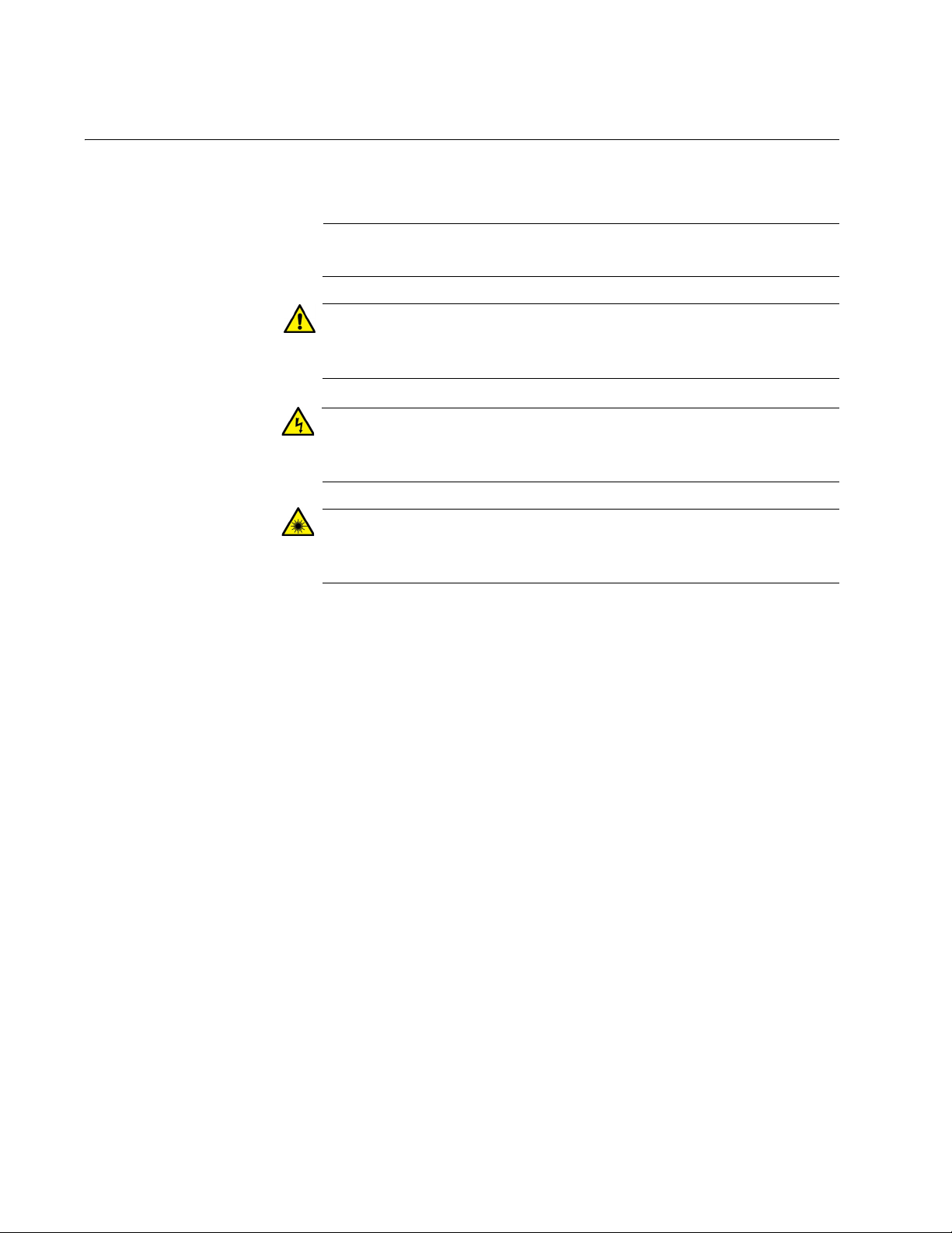
Caution
Warning
Warning
This document uses the following conventions:
Notes provide additional information.
Cautions inform you that performing or omitting a specific action
may result in equipment damage or loss of data.
Warnings inform you that performing or omitting a specific action
may result in bodily injury.
Warnings inform you that an eye and skin hazard exists due to the
presence of a Class 1 laser device.
2
Page 13

Contacting Allied Telesis
If you need assistance with this product, you may contact Allied Telesis
technical support by going to the Support & Services section of the Allied
Telesis web site at
the following services on this page:
24/7 Online Support - Enter our interactive support center to
search for answers to your questions in our knowledge database,
check support tickets, learn about RMAs, and contact Allied
Telesis technical experts.
USA and EMEA phone support - Select the phone number that
best fits your location and customer type.
Hardware warranty information - Learn about Allied Telesis
warranties and register your product online.
Replacement Services - Submit a Return Merchandise
Authorization (RMA) request via our interactive support center.
AT-x220-28GS Switch Installation Guide
www.alliedtelesis.com/support. You can find links for
Documentation - View the most recent installation guides, user
guides, software release notes, white papers and data sheets for
your product.
Software Updates - Download the latest software releases for your
product.
For sales or corporate contact information, go to
www.alliedtelesis.com/purchase and select your region.
3
Page 14

User documentation
For full AlliedWare Plus documentation and product information, see our
Resource Library at:
http://www.alliedtelesis.com/support
From the Resource Library the following documents are available:
Datasheets
Click on the link above and search for the product series.
Installation guides
Click on the link above and search for the product series.
Getting Started with AlliedWare Plus Feature Overview and
Configuration Guide
Click on the link above and search for ‘Getting started with
AlliedWare Plus’.
Feature Overview and Configuration Guides
Click on the link above and search for the feature name.
Command References
Click on the link above and search for the product series.
You can also find a range of helpful case studies, solution guides,
whitepapers and videos.
4
Page 15

Chapter 1
Overview
AT-x220-28GS Switch Installation Guide
This chapter provides descriptions of the AT-x220-28GS Gigabit Ethernet
Switch and contains the following sections:
“Features” on page 6
“Package contents for the AT-x220-28GS Switch” on page 8
“Front and back panels on the AT-x220-28GS Switch” on page 9
“LEDs” on page 10
“Ecofriendly button” on page 14
“Power supply” on page 15
“Fans” on page 15
5
Page 16

Chapter 1: Overview
Note
Features
SFP slots Ports 1-24 are 100BASE-FX or 1000BASE-X Ethernet LAN ports.
Transceivers Available for 100Mbps or 1000Mbps of fiber, and 1000Mbps of
This section describes the hardware features on the front panel of the ATx220-28GS switch.This model is a Gigabit Advanced Smart-Managed
switch with a total of 28 1 Gbps SFP ports.
Ports 25-28 are 100BASE-FX or 1000BASE-X Ethernet Uplink
ports.
copper.
Support 100BASE-FX and 1000BASE-SX/LX SFP transceivers.
SFP transceivers must be purchased separately. For a list of supported
transceivers, contact your Allied Telesis distributor or reseller.
See the product Datasheet for the specific ATI SFP modules
supported by the x220-28GS switch.
USB slot The Management Panel has a USB 2.0 compatible host port, see “USB
LED” on page 13. You may use the port to store configuration files on
flash drives or to restore configuration files to switches whose settings
have been lost or corrupted, or to quickly configure replacement units. You
may also use the port and flash drives to update the management
firmware on the switch.
Console port The Management Panel has a RS-232 serial management port with an
RJ-45 connector. You use the port to access the AlliedWare Plus
management software on the switch to configure the feature settings or
monitor status or statistics. See
page 34.
“Starting a local management session” on
LEDs Here is a brief description of the LEDs:
Power and Fault LEDs; refer to “Power and Fault LEDs” on
page 10.
Link/Activity LEDs for the SFP slots; see “SFP LEDs” on page 11.
USB LED; refer to “USB LED” on page 13.
6
Page 17

AT-x220-28GS Switch Installation Guide
Note
The ecofriendly button on the Management Panel turns off the port
LEDs to conserve electricity (excluding the Fault, Power and USB
LEDs). See “Ecofriendly button” on page 14.
Power
conservation
MAC address
table
Installation
options
Management
software and
interfaces
These switches have the following power conservation features:
Ecofriendly button to turn off the port LEDs when the system is not
being monitored
High efficiency power supply
Here are the basic features of the MAC address table:
Storage capacity up to 16K MAC address entries
Automatic learning and aging
The switches can be installed in the following ways:
Mounted on a desk or tabletop
Rack mounted in a 19-inch equipment rack
Wall mounted
Here are the management software and interfaces:
AlliedWare Plus Management Software
Command Line Interface
Management
methods
Web browser interface
Here are the methods for managing the switches:
Local management through the console port
Remote Telnet or Secure Shell management
Remote HTTP and HTTPS web browser management
7
Page 18
Chapter 1: Overview
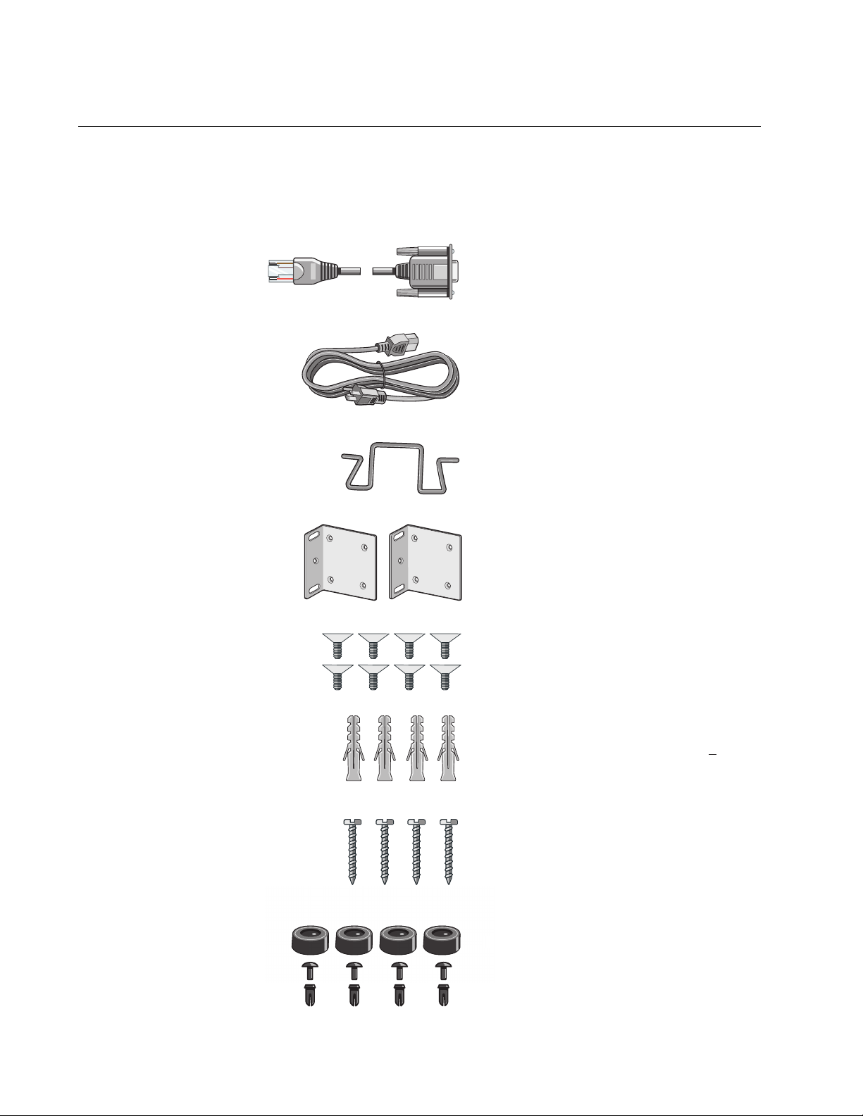
One 2 m (6.6ft) local management cable
with RJ-45 (8P8C) and DB-9 (D-sub 9-pin)
One regional AC power cord
Power cord retaining clip
Two rack/wall mounting brackets
Eight bracket screws
Four anchors for concrete walls:
Length: 29.6 mm (1 1/8 in)
Diameter: 6.0 mm (0.25 in)
Four screws for wood or concrete walls:
Length: 31 mm (1/14 in)
Width: 4.3 mm (1/8 in)
Four rubber feet with push-in snap rivets
o
Package contents for the AT-x220-28GS Switch
Figure 1 illustrates the package components that come with the AT-x22028GS Gigabit Ethernet Switch.
Figure 1. AT-x220-28GS packaging
8
F
Page 19

Front and back panels on the AT-x220-28GS Switch
272825
26
35179111315171921 23
46810122 16 18 2014
22 24
1000 LINK ACT 100 LINK ACT
AT-x220-28GS
FAULT
POWER
USB
ON ACT
ERR
CLASS
1
LASER PRODUCT
CONSOLE
ecofriendly button
USB slot
Console port
USB/Fault/Power LEDs
SFP Network ports
Upper (left), lower (right)
SFP port LEDs:
SFP uplink ports
Power connector
Power cable hook
Power cable hook mount
Figure 2 illustrates the front panel of the AT-x220-28GS Gigabit Ethernet
Switch.
Figure 2. AT-x220-28GS front panel
AT-x220-28GS Switch Installation Guide
Figure 3 illustrates the back panel of the AT-x220-28GS Gigabit Ethernet
Switch.
Figure 3. AT-x220-28GS back panel
9
Page 20

Chapter 1: Overview
Note
27
28
FAULT
POWER
USB
ON ACT
ERR
CLASS1
LASER PRODUCT
CONSOLE
Power LED
LEDs
This section describes the four types of LEDs on the AT-x220-28GS
switch:
“Power and Fault LEDs” on page 10
“SFP LEDs” on page 11
“USB LED” on page 13
Power and Fault
LEDs
The Power LED reports the status of AC power and is located on the
Management Panel of the switches beside the console port. See Figure 4.
All port LEDs are OFF when the switch is operating in the low power
mode. To toggle on the LEDs, use the ecofriendly button. See
“Ecofriendly button” on page 14 for more information.
Figure 4. Power LED on the AT-x220-28GS Switch
10
Table 1 describes the Power LED for the AT-x220-28GS switch.
Table 1. Power LED functional descriptions
LED State
Description
Indicates either the switch is not receiving AC
ower or the AC input power is operating outside
p
the normal range
The switch is receiving AC input power
Power
Off
Steady
een
gr
Page 21

AT-x220-28GS Switch Installation Guide
27
28
FAULT
POWER
USB
ON ACT
ERR
CLASS1
LASER PRODUCT
CONSOLE
Fault LED
Note
Figure 5 shows the location of the Fault LED.
Figure 5. Fault LED on the AT-x220-28GS Switch
Table 2 describes the functions of the Fault LED.
Table 2. Fault LED functional descriptions
LED State Description
Off
If the POWER LED is on, the switch is receiving
put power and is operating normally
AC in
Fault
Red
flashing
Indicates system warning such as a high
mperature alarm
te
SFP LEDs The AT-x220-28GS switch has a total of 28 SFP ports. Each SFP port has
an SFP Link/Speed/Activity LED on the front panel. See Figure 6.
The SFP Link/Speed/Activity LEDs indicate the activity status for ea
SFP slot. Each SFP slot has ONE bi-color LED:
The left LED corresponds to the upper SFP port
The right LED corresponds to the lower SFP port
All of the port LEDs are OFF when the switch is operating in
ecofriendly mode. See
“Ecofriendly button” on page 14 for more
information.
ch
11
Page 22

Chapter 1: Overview
27
28
25
26
23
24
CONSO
Upper (left) SFP LED
Lower (right) SFP LED
SFP slots
Figure 6. SFP Link/Speed/Activity LEDs on the AT-x220-28GS Switch
Table 3 describes the functions of the SFP Link/Speed/Activity LEDs:
Table 3. SFP Link/Activity LED functional descriptions
LED State Description
The port on the SFP transceiver has not
Off
ablished a link with an end node, or the
est
ecofriendly feature is enabled
SFP
Flashing
green
Steady
green
Flashing
amber
Steady
amber
Rx or Tx activities at 1000M
The SFP transceiver has established a
00M link with a network device
10
Rx or Tx activities at 100M
The SFP transceiver has established a 100M
Link with a ne
twork device
12
Page 23

AT-x220-28GS Switch Installation Guide
Note
27
28
FAULT
POWER
USB
ON ACT
ERR
CLASS1
LASER PRODUCT
CONSOLE
USB LED
USB Slot
USB LED The AT-x220-28GS switch has a single bi-color USB LED on the
Management Panel (see Figure 7)
All of the port LEDs are off when the switch is operating in
ecofriendly mode. See
information.
Figure 7. USB slot LED on the AT-x220-28GS Switch
“Ecofriendly button” on page 14 for more
The USB LED indicates whether the USB slot has a USB inserted, or is
reading or writing to the USB device. Table 4 describes the functions of
the USB LED.
Table 4. USB LED functional descriptions
LED State Description
Off No USB device detected
USB
Flashing
en
gre
Steady
en
gre
Flashing
ambe
Writing or reading
USB device inserted and recognized for use
Writing or reading error
r
13
Page 24

Chapter 1: Overview
27
28
FAULT
POWER
USB
ON ACT
ERR
CLASS1
LASER PRODUCT
CONSOLE
ecofriendly button
Note
Ecofriendly button
By pressing the ecofriendly button on the Management Panel, you can
conserve energy.
Using the button When you press the ecofriendly button for 1 to 4 seconds, the front panel
port LEDs are disabled. You may use the button to turn off the LEDs when
you are not monitoring the switch. To turn the port LEDs on, press the
ecofriendly button for 1 to 4 seconds again. Toggling the LEDs does not
affect the network operations of the switch.
Using commands The management software on the switch has a command that blinks the
LEDs so that you can quickly and easily identify a specific unit among the
devices in an equipment rack. It is the findme command. The command
works on the switch even if you turned off the LEDs with the ecofriendly
button or by using the no ecofriendly led command.
Figure 8. ecofriendly button on the AT-x220-28GS switch
s
The ecofriendly button does not control the Fault, Power or USB
LEDs.
Troubleshooting Before checking or troubleshooting the network connections to the ports
on the switch, you should always check to be sure that the LEDs are on by
either pressing the ecofriendly button or issuing the ecofriendly led and
no ecofriendly led commands in Global Configuration mode.
14
Page 25

Power supply
Warning
Fans
AT-x220-28GS Switch Installation Guide
Each switch has an internal power supply with a single AC power supply
socket on the back panel. A power cord and a power cord retainer hook
are supplied with the switch. The power supply is not field replaceable.
Power cord is used as a disconnection device. To de-energize
equipment, disconnect the power cord. E3
For the power requirements, see “Power specifications” on page 44.
Each switch has an internal fan.You cannot remove or replace these fans
in the field. The fan status is indicated with the Fault LED. See
Fault LEDs” on page 10 and Table 2 on page 11 for more information.
“Power and
15
Page 26

Chapter 1: Overview
16
Page 27

Chapter 2
Installation
This chapter contains the following sections:
AT-x220-28GS Switch Installation Guide
“Reviewing safety precautions” on page 18
“Selecting a site for the switch” on page 21
“Unpacking the switch” on page 22
“Installing the switch on a table or a desktop” on page 23
“Removing the feet before installing the switch in an equipment
rack or on a wall” on page 25
“Installing the switch in an equipment rack” on page 26
“Installing the switch on a wall” on page 28
“Powering on the switch” on page 33
“Management software” on page 35
“Starting a local management session” on page 36
“Monitoring the initialization processes” on page 37
“Cabling the Network Ports” on page 41
“Installing SFP transceivers” on page 42
17
Page 28

Chapter 2: Installation
Note
Warning
Warning
Warning
Warning
Caution
Reviewing safety precautions
Please review the following safety precautions before you begin to install
the chassis or any of its components.
The indicates that a translation of the safety statement is
available in a PDF document titled Translated Safety Statements.
To prevent electric shock, do not remove the cover. No userserviceable parts inside. This unit contains hazardous voltages and
should only be opened by a trained and qualified technician. To
avoid the possibility of electric shock, disconnect electric power to
the product before connecting or disconnecting the cables. E1
Do not work on equipment or cables during periods of lightning
activity. E2
Power cord is used as a disconnection device. To de-energize
equipment, disconnect the power cord. E3
Class I Equipment. This equipment must be earthed. The power
plug must be connected to a properly wired earth ground socket
outlet. An improperly wired socket outlet could place hazardous
voltages on accessible metal parts. E4
Pluggable equipment: The socket outlet shall be installed near the
equipment and shall be easily accessible. E5
Air vents must not be blocked and must have free access to the
room ambient air for cooling. E6
18
Operating temperature: This product is designed for a maximum
ambient temperature of 50° degrees C. E7
Page 29

AT-x220-28GS Switch Installation Guide
Warning
Warning
Warning
Warning
Caution
All countries: Install product in accordance with local and National
Electrical Codes. E8
Only trained and qualified personnel are allowed to install or replace
this equipment. E14
Circuit overloading: Consideration should be given to the
connection of the equipment to the supply circuit and the effect that
overloading of circuits might have on overcurrent protection and
supply wiring. Appropriate consideration of equipment nameplate
ratings should be used when addressing this concern. E21
Mounting of the equipment in the rack should be such that a
hazardous condition is not created due to uneven mechanical
loading. E25
Use dedicated power circuits or power conditioners to supply
reliable electrical power to the device. E27
The chassis may be heavy and awkward to lift. Allied Telesis
recommends that you get assistance when mounting the chassis in
an equipment rack. E28
If installed in a closed or multi-unit rack assembly, the operating
ambient temperature of the rack environment may be greater than
the room ambient temperature. Therefore, consideration should be
given to installing the equipment in an environment compatible with
the manufacturer’s maximum rated ambient temperature (Tmra).
E35
Installation of the equipment in a rack should be such that the
amount of air flow required for safe operation of the equipment is not
compromised. E36
19
Page 30

Chapter 2: Installation
Warning
Caution
Warning
Caution
Warning
Reliable earthing of rack-mounted equipment should be maintained.
Particular attention should be given to supply connections other than
direct connections to the branch circuits (e.g., use of power strips).
E37
The unit does not contain serviceable components. Please return
damaged units for servicing. E42
The temperature of an operational SFP transceiver may exceed 70°
C(158° F) Exercise caution when removing or handling a transceiver
with unprotected hands. E43
An Energy Hazard exists inside this equipment. Do not insert hands
or tools into open chassis slots or plugs. E44
This equipment shall be installed in a Restricted Access location.
E45
20
Page 31

Selecting a site for the switch
Warning
You can install an AT-x220-28GS switch on a table or desktop, in a
standard 19-inch equipment rack, or on a wall.
Observe the following requirements when choosing a site for your switch:
If you are installing the switch on a table, verify that the table is
level and secure.
If you plan to install the switch in an equipment rack, verify that the
rack is safely secured and will not tip over. Devices in a rack should
be installed starting at the bottom, with the heavier devices near
the bottom of the rack.
If you are installing the switch on a wall, ensure that the wall is
sturdy enough to hold the switch’s weight. You may need to
position the switch so that it can be screwed into the wall’s framing
timber or an equivalent structural element.
AT-x220-28GS Switch Installation Guide
The power outlet for the switch should be located near the unit and
should be easily accessible.
The site should provide for easy access to the ports on the front of
the switch. This will make it easier for you to connect and
disconnect cables, as well as view the switch’s LEDs.
The site should allow for adequate air flow around the unit and
through the cooling vents on the front and rear panels. (The
ventilation direction is from front to back.)
Do not place objects on top of the switch.
Do not expose the switch to moisture or water.
Ensure that the site is in a dust-free environment.
Do not install the switch in a wiring or utility box because it might
overheat and fail from inadequate airflow.
You should use dedicated power circuits or power conditioners to
supply reliable electrical power to the network devices.
Switches should not be stacked on a table or desktop. They could
present a physical safety hazard if you need to move or replace
switches. E91
21
Page 32

Chapter 2: Installation
Note
o
Unpacking the switch
To unpack the switch, perform the following procedure:
1. Remove all of the components from the shipped package.
2. Place the switch on a level, secure surface.
Store the packaging material in a safe location. You must use the
original shipping material if you need to return the unit to Allied
Telesis.
3. Verify that the shipped package include
One 2 m (6.6ft) local management cable
with RJ-45 (8P8C) and DB-9 (D-sub 9-pin)
One regional AC power cord
Power cord retaining clip
Two rack/wall mounting brackets
Eight bracket screws
s the following items:
Four anchors for concrete walls:
Length: 29.6 mm (1 1/8 in)
Diameter: 6.0 mm (0.25 in)
Four screws for wood or concrete walls:
Length: 31 mm (1/14 in)
Width: 4.3 mm (1/8 in)
Four rubber feet with push-in snap rivets
F
22
Page 33

Installing the switch on a table or a desktop
Note
Note
Here are the guidelines to selecting a suitable site for desktop or table use:
Review the procedure “Selecting a site for the switch” on page 21
to verify that the selected site is suitable for your switch.
The rubber feet included in the packaging should be attached to
the switch for table or desktop installation.
AT-x220-28GS Switch Installation Guide
If your switch does not already have rubber feet fitted, fit these as
follows:
1. Turn the switch over and place it on a table.
2. Remove the rubber feet, rivet pins and rivet housings from the
ging.
packa
The feet are reusable. If they have been used previously, they may
be already assembled, with the rivet locked in place. To re-use
them, first push the rivets out of the feet. Then separate the rivet pin
and housing from each other, so that you can insert them as
described below.
3. Assemble the rivets by inserting the Pin into the Housing as shown in
Figure 9 on page 23.
Figure 9. Assembling the rivets
Insert all rivet pins into the rivet housings
Do not press the pin all the way down to lock the rivet.If you do
engage the rivet lock, prise the pin out of the housing, so you can reassemble and re-use it.
23
Page 34

Chapter 2: Installation
4. Insert the rivet through the hole in the feet as shown in Figure 10 on
page 24.
Figure 10. Inserting the assembled rivets into the hole in the foot
Insert all assembled rivets into the holes in the feet
5. Place the feet with the rivet inserted into the base holes on
the switch.
Figure 11. Placing the feet with rivets on the switch
6. Push the feet firmly into holes on the base of the switch so that the
rivets lock the feet in place as shown in Figure 12 on page 24
Figure 12. Attaching the rubber feet to a switch
24
26
LASER PRODUCT
CLASS1
ERR
CONSOLE
ON ACT
USB
POWER
FAULT
272825
22 24
1000 LINK ACT 100 LINK ACT
46810122 16 18 2014
35179111315171921 23
AT-x220-28GS
7. Turn the switch over again and place it on a flat, secure surface (such
as a desk or table), leaving ample space around the unit for ventilation.
Page 35

AT-x220-28GS Switch Installation Guide
Note
Removing the feet before installing the switch in an equipment rack or on a wall
Before you install the switch in a 19-inch equipment rack or on a wall, you
need to remove the rubber feet, if they are attached to the base of the
switch. To do this, follow these steps:
1. Place the unit upside down on a level, secure surface.
2. Use a small flat-head screwdriver to pry the four rubber feet a
rivets from the bottom of the switch. Figure 13 shows how to do this on
an AT-x220-28GS switch.
Figure 13. Removing the rubber feet and rivets from a switch
3. Turn the switch back over.
The feet are reusable. To re-use them, first push the rivets out of the
feet. Then separate the rivet pin and housing from each other, so
that you can insert them as described in
table or a desktop” on page 23.
“Installing the switch on a
nd their
25
Page 36

Chapter 2: Installation
Installing the switch in an equipment rack
These instructions show you how to install the switch in an equipment
rack. The rack mount kit is included in the packaging and includes two
rack mount brackets and eight bracket screws.
To install one of these switches in a 19
steps:
1. Review the procedure “Selecting a site for the switch” on page 21 to
verify that the selected site is suitable for your switch.
2. If rubber feet are attached to the base of the switch, remove them
(Figure 13 on page 25).
3. Attach the two rack mount brackets to the sides of the switch u
eight bracket screws that come with the rack mount kit provided. See
“Unpacking the switch” on page 22.
Figure 14. Attaching rack mount brackets to the AT-x220-28GS
h
switc
-inch equipment rack, follow these
sing the
26
Page 37

AT-x220-28GS Switch Installation Guide
27
28
25
26
3 5
1 7 9
11
13 15 17 19 21 23
4 6 8
10122 1618 2014
22 24
1000 LINK ACT 100 LINK ACT
AT-x220-28GS
FAULT
POWER
USB
ON
ACT
ERR
CLASS1
LASER PRODUCT
CONSOLE
4. Mount the switch in a 19-inch equipment rack using four equipment
rack screws (not supplied).
Figure 15. Mounting the AT-x220-28GS switch in an equipment rack
27
Page 38

Chapter 2: Installation
Caution
Installing the switch on a wall
These instructions show you how to install the switch on a wall. The rack/
wall mount brackets and screws are provided along with the screws for
securing the switch to a wall with wooden studs. Concrete anchors are
also provided for concrete walls.
Review the procedure “Selecting a site for the switch” on page 21 to verify
that the selected site is suitable for your switch.
Before you start, ensure that the wall is sturdy enough to hold the switch’s
weight. You may need to position the switch so that it can be screwed into
the wall’s framing timber or an equivalent structural element. The wall
location for the switch must provide adequate space to the front and back
panels so that you can service the unit, and for ventilation.
Wall guidelines Here are the guidelines to installing the switch on a wall:
You may install the switch on a wall that has wooden studs
Tools and
materials
You may install the switch on a concrete wall
You should not install the switch on a metal stud. Metal studs may
not be strong enough to safely support the device.
Here are the required tools and material for installing the switch on a wall:
Eight bracket screws (provided with the switch)
Two wall or equipment rack brackets (provided with the switch)
Four wall screws (provided with the switch for wood or concrete)
Four concrete anchors (provided with the switch)
Flat-head screwdriver (not provided)
Cross-head screwdriver (not provided)
Stud finder for a wooden wall, capable of identifying the middle of
wooden studs and hot electrical wiring (not provided)
Drill and a 1/4’’ carbide drill for a concrete wall (not provided)
The supplied screws and anchors may not be appropriate for all
walls. A qualified building contractor should determine the hardware
requirements for your wall prior to installing the switch.
28
Page 39

AT-x220-28GS Switch Installation Guide
Positions of the
switch on a wall
The switch may be installed on the wall with the front panel on the left or
right with the brackets placed diagonally as shown in Figure 16.
Do not install the switch with the front panel on the top or the bo
Figure 16. Positioning the switch on the wall
ttom.
Install the switch
on the wall
To install the switch on a wall, perform the following procedure:
1. If the rubber feet are attached to the bottom of the switch, remove
them with a screwdriver (Figure 13 on page 25), then turn the switch
back over.
2. Orient the brackets against the sides of the switch and secure
the unit with the 8 bracket screws included in the rack/wall mount kit.
You can either attach the brackets facing left or right as shown in
Figure 17 and Figure 18.
them to
29
Page 40

Chapter 2: Installation
Left facing Figure 17. Attaching wall mount brackets so that the switch is left
facing
Right facing Figure 18. Attaching wall mount brackets so that the switch right
facing
30
3. While another person holds the switch at the wall location, use a pencil
to mark the wall with the locations of the two screw holes for each
bracket. (Figure 19).
Page 41

AT-x220-28GS Switch Installation Guide
Figure 19. Marking the screw holes from the brackets to the wall
4. While another person holds the switch at the marked wall location, use
a drill to make the holes for the two screws for each bracket. (Figure
20).
5. If you are installing the switch on a concrete wall, use the f
our concrete
anchors provided in the drill holes.
6. Use the four screws provided to secure the switch to the wall.
Figure 20. Securing the switch to the wall
31
Page 42

Chapter 2: Installation
Powering on the switch
To power on the switch, perform the following procedure:
1. Attach the power cable hook and lift to the up position ready f
power plug to be inserted, as shown in Figure 21, on the back of the
switch.
Figure 21. Attaching the AC power cable hook on the switch
or the AC
2. Plug the power cord into the AC power connector, as shown in
Figure 22, on the back of the switch.
Figure 22. Plugging in the AC power cord on the Switch
32
Page 43

AT-x220-28GS Switch Installation Guide
Warning
3. Plug the other end of the power cord into a wall outlet.
Power cord is used as a disconnection device. To de-energize
equipment, disconnect the power cord. E3
Pluggable Equipment: The socket outlet shall be installed near the
equipment and shall be easily accessible. E5
4. Verify that the power LED is green. If the LED is off, see Chapter 3,
“Troubleshooting” on page 45.
The switch is now powered on and ready for network operations.
33
Page 44

Chapter 2: Installation
Management software
The switches are shipped with the management software pre-installed.
The software provides a command line interface and a GUI (Graphical
User Interface) for in-band, over-the-network management.
In the unlikely event that the management software becomes corrupted or
damaged on the switch, you can download the software from the Allied
Telesis corporate web site and reinstall it on the switch. For instructions on
how to install new management software, see our Software Library at:
http://www.alliedtelesis.com/support
34
Page 45

Starting a local management session
27
28
25
26
21 23
2224
FAULT
POWER
USB
ON
ACT
ERR
CLASS1
LASER PRODUCT
CONSOLE
Note
This procedure requires a terminal or a terminal emulator program and the
management cable that comes with the switch. To start a local
management session on the switch, perform the following procedure:
1. Connect the RJ45 connector on the management cable to the console
t on the front panel of the switch, as shown below.
por
Figure 23. Connecting the management cable to the console port of
x220 Series Switch
the
AT-x220-28GS Switch Installation Guide
2. Connect the other end of the cable to an RS-232 port on a terminal or
PC with a terminal emulator program.
3. Configure the terminal or terminal emulator program as follows:
Baud rate: 9600 bps (The baud rate of the Console Port is
adjustable from 1200 to 115200 bps. The default is 9600 bps.)
Data bits: 8
Parity: None
Stop bits: 1
Flow control: None
The port settings are for a DEC VT100 or ANSI terminal, or an
equivalent terminal emulator program.
4. If you have not already done so, power up the switch as described in
the previous steps.
35
Page 46

Chapter 2: Installation
Verifying release... OK
Booting...
Starting base/first... [ OK ]
Mounting virtual filesystems... [ OK ]
______________ ____
/\ \ / /______\
/ \ \_ __/ /| ______ |
/ \ | | / | ______ |
/ \ \ / / \ ____ /
/______/\____\ \/ /____________/
Allied Telesis Inc.
AlliedWare Plus (TM) v0.0.0
Current release filename:x220-5.4.8.rel
Built: Fri Mar 23 07:06:12 UTC 2018
Mounting static filesystems... [ OK ]
Attaching to /dev/mtd0... [ OK ]
Mounting file system... [ OK ]
Checking for last gasp debug output... [ OK ]
Checking NVS filesystem... [ OK ]
Mounting NVS filesystem... [ OK ]
Initializing random number generator... [ OK ]
Starting base/hwrandom... [ OK ]
Starting base/dbus... [ OK ]
Starting base/linux... [ OK ]
Starting base/syslog... [ OK ]
Starting base/loopback... [ OK ]
Starting base/poe_done... [ OK ]
Starting base/portmapper... [ OK ]
Received event syslog.done
Starting base/modules... [ OK ]
Monitoring the initialization processes
It takes about thirty seconds for the switch to initialize its management
software programs and features, and load the default configuration.
You may also monitor the bootup seq
uence by connecting a terminal or
computer that has a terminal emulator program, to the console port on the
master switch. You will see the messages from Figure 24 below to Figure
26 on page 40.
Figure 24. Switch initialization messages
36
Page 47

Figure 25. Switch initialization messages (continued)
Received event modules.done
Starting base/reboot-stability... [ OK ]
Checking system reboot stability... [ OK ]
Starting base/apteryx... [ OK ]
Starting base/crond... [ OK ]
Starting base/appmond... [ OK ]
Starting base/clockcheck... [ OK ]
Starting base/inet... [ OK ]
Received event apteryx.done
Starting hardware/early_host_info... [ OK ]
Starting base/eventwatch... [ OK ]
Starting base/alfred... [ OK ]
Starting network/kermond... [ OK ]
Starting base/apteryx-sync... [ OK ]
Starting base/logconf... [ OK ]
Received event apteryx-sync.done
Starting hardware/plugman... [ OK ]
Starting hardware/openhpi... [ OK ]
Starting hardware/timeout... [ OK ]
Received event board.inserted
Starting hardware/hardware-done... [ OK ]
Received event hardware.done
Starting network/startup... [ OK ]
Starting base/external-media... [ OK ]
Received event hostcfg.done
Starting network/licd... [ OK ]
Starting network/stackd... [ OK ]
Starting network/election.timeout... [ OK ]
Starting network/corosync... [ OK ]
Received event network.enabled
Initializing HA processes:
atmf_agentd, exfx, hostd, auth, imiproxyd, lldpd, nsm
sflowd, hsl, irdpd, lacp, mstp, ripd, rmon
atmfd, cntrd, epsr, imi, loopprot, ripngd, udldd
Received event network.initialized
AT-x220-28GS Switch Installation Guide
37
Page 48

Chapter 2: Installation
Assigning Active Workload to HA processes:
hsl, irdpd, lacpd, loopprotd, mstpd, nsm, ripd
rmond, sflowd, authd, epsrd, lldpd, imi, imiproxyd
Received event network.activated
Loading default configuration
Warning: flash:/default.cfg does not exist, loading factory defaults.
.
done!
Received event network.configured
awplus login:
Figure 26. Switch initialization messages (continued)
38
Page 49

Cabling the Network Ports
Caution
Observe the following guidelines before installing SFP transceivers on the
switch.
The transceivers are hot-swappable. You can install them while the
switch is powered on.
For a list of supported transceivers, refer to the product data sheet
on the Allied Telesis web site.
The operational specifications and fiber optic cable requirements of
the transceivers are provided in the documents included with the
devices.
You should install a transceiver before connecting its fiber optic
cable.
Unnecessary removal and insertion of a transceiver can lead to
premature failure.
AT-x220-28GS Switch Installation Guide
Transceivers can be damaged by static electricity. Be sure to
observe all standard electrostatic discharge (ESD) precautions, such
as wearing an anti-static wrist strap, to avoid damaging the devices.
E92
39
Page 50

Chapter 2: Installation
Note
Note
Warning
27
28
25
26
FAULT
POWER
USB
ON
ACT
ERR
CLASS1
LASER PRODUCT
CONSOLE
Installing SFP transceivers
To install an SFP transceiver, perform the following procedure:
The transceiver can be hot-swapped; you do not need to power off
the switch to install a transceiver. However, always remove the
cables before removing the transceiver.
You should always install the transceiver before connecting the fiber
optic cables to it.
1. Remove the transceiver from its shipping container and store the
packaging material in a safe location.
An SFP transceiver can be damaged by static electricity. Be sure to
observe all standard electrostatic discharge (ESD) precautions,
such as wearing an anti-static wrist strap, to avoid damaging the
transceiver.
2. Position the SFP transceiver with the Allied Telesis label facing up for
the top SFP slots. Position the SFP transceiver with the Allied Telesis
label facing down for the bottom SFP slots.
3. Gently slide the transceiver into the SFP slot until it clicks
into place as
shown in Figure 27.
Figure 27. Inserting an SFP transceiver into an SFP slot
40
Page 51

AT-x220-28GS Switch Installation Guide
27
28
25
26
FAULT
POWER
USB
ON
ACT
ERR
CLASS1
LASER PRODUCT
CONSOLE
SFP Transceiver
Handle
27
28
25
26
FAULT
POWER
USB
ON
ACT
ERR
CLASS1
LASER PRODUCT
CONSOLE
Note
4. Verify that the handle on the transceiver is in the upright position, as
shown in Figure 28. This secures the transceiver and prevents it from
being dislodged from the slot. If th
e transceiver is in a bottom slot verify
the handle is in the downright position.
Figure 28. Positioning the SFP handle in the upright position
5. Eject SFP transceivers, as shown in Figure 29. First lower the SFP
transceiver handle, then gently remove the SFP transceiver. If the
sceiver is in a bottom slot, then raise the handle.
tran
Figure 29. Ejecting an SFP transceiver after lowering the SFP handle
to the
downwards position
6. Repeat steps 2 through 6 to install an additional SFP transceiver.
Unnecessary removal and insertion of an SFP transceiver can lead
to premature failure.
For information on the cable specifications of the SFP, consult the
documentation shipped with the SFP.
41
Page 52

Chapter 2: Installation
42
Page 53

Chapter 3
Note
Troubleshooting
This chapter contains information on how to troubleshoot the switch if a
problem occurs.
For further assistance, please contact Allied Telesis Technical
Support at www.alliedtelesis.com/support.
Problem 1: The power LED on the front of the switch is off.
Solutions: The unit is not receiving power. Try the following:
Verify that the power cord is securely connected to the power
source and to the AC connector on the back panel of the switch.
AT-x220-28GS Switch Installation Guide
Verify that the power outlet has power by connecting another
device to it.
Try connecting the unit to another power source.
Try a different power cord.
Verify that the voltage from the power source is within the required
levels for your region.
Problem 2: All of the port LEDs are off even though the ports are
connected to active network devices.
Solution: The switch is probably operating in low power mode. To toggle
on the LEDs, press the ecofriendly button on the front panel for 1 to 4
seconds.
Problem 3: The Link/Activity/Speed LED for an SFP transceiver is off.
Solutions: The fiber optic port on the transceiver is unable to establish a
link to a network device. Try the following:
Verify that the remote network device connected to the fiber optic
port is operating properly.
Verify that the fiber optic cable is securely connected to the port on
the media converter channel and to the port on the remote network
device.
Check that the SFP module is fully inserted in the slot.
Verify that the operating specifications of the fiber optic ports on
the SFP transceiver and the remote network device are
compatible.
45
Page 54

Chapter 3: Troubleshooting
Verify that the correct type of fiber optic cabling is being used.
Verify that the port is connected to the correct fiber optic cable.
This is to eliminate the possibility that the port is connected to the
wrong remote network device, such as a powered off device.
Try connecting another network device to the fiber optic port using
a different cable. If the port is able to establish a link, then the
problem is with the cable or with the other network device.
Use the switch’s management software to verify that the port is
enabled.
If the remote network device is a management device, use its
management firmware to determine whether its port is enabled.
Test the attenuation on the fiber optic cable with a fiber optic tester
to determine whether the optical signal is too weak (sensitivity) or
too strong (maximum input power).
Problem 4: The switch functions intermittently.
Solutions: Check the system hardware status through the management
software:
Use the show system environment command in the Privileged
Exec mode to verify that the input voltage from the power source to
the switch is stable and within the approved operating range. The
unit will shut down if the input voltage fluctuates above or below
the approved operating range.
Use the show system environment command in the Privileged
Exec mode to verify that the fan is operating correctly.
Verify that the location of the switch allows for adequate airflow.
The unit will shut down if it is in danger of overheating.
Problem 5: A port’s Link/Activity/Speed LED is blinking.
Solutions: The link between the port and the network device is
intermittent. Try the following:
Connect another network device with a different cable to the port. If
the Link LED remains steady on, then the problem is with the
original cable or the network device.
If the problem is with an SFP transceiver, check that the
transceiver is fully inserted in the slot.
46
Page 55

Appendix A
Technical specifications
This appendix describes the technical specifications of an x220 series
switch.
Physical specifications
Dimensions
TABLE 5. CHASSIS DIMENSIONS
Model W x D x H mm (in)
AT-x220-28GS Switch Installation Guide
Weight
AT-x220-28GS
TABLE 6. CHASSIS WEIGHT
Model Weight
AT-x220-28GS 4.3 kg (9.47 lb)
341 mm x 231mm x 44mm
2 in x 9.10 in x 1.73 in)
(13.4
47
Page 56

Appendix A: Technical specifications
Environmental specifications
TABLE 7. ENVIRONMENTAL SPECIFICATIONS
Operating temperature 0° C to +50° C (32° F to 122° F)
Storage temperature -25° C to 70° C (-4° F to 158° F)
Operating humidity < 90% non-condensing
Storage humidity < 95% non-condensing
Operating altitude range Up to 3,000 m (9,842 ft)
Power specifications
TABLE 8. INPUT SUPPLY VOLTAGE
Model Input supply voltage
AT-x220-28GS 100-240 VAC, 50 - 60 Hz, 0.60A maximum
T
ABLE 9. POWER SPECIFICATIONS
Model Power budget
AT-x220-28GS N/A 75 W
Maximum power
consum
ption
48
Page 57

Electrical safety and electromagnetic certifications
TABLE 10. SAFETY AND ELECTROMAGNETIC EMISSIONS CERTIFICATIONS
EMC EN 55024
EN 55032 Class A
EN 61000-3-2
EN 61000-3-3
FCC Part 15 (CFR 47) Class A
VCCI Class A
CISPR 22 Class A
ICES-003
AT-x220-28GS Switch Installation Guide
Environmental
compliance
Electrical safety EN 60950-1 (edition 2)
Laser safety EN 60825
Regulatory
Complia
nce
RoHS
WEEE
IEC 60950-1 (edition 2)
UL 60950-1 (edition 2)
C-UL-US
TUV-T-Mark
RCM
CE
49
Page 58

Appendix A: Technical specifications
Connectors and port pinouts for the console port
This section lists the connectors and connector pinouts for the
management console port.
Figure 30 illustrates the pin layout for an RJ45 connector for the console
port.
Figure 30. RJ45 connector and port pin layout
Table 11 lists the RJ-45 style serial consol port pin signals.
Table 11. RJ-45 Style Serial Consol Port Pin Signals
Pin Signal
1 Looped to pin 8
2 Looped to pin 7
50
3 Transmit Data x220-28GS Tx Output pin
4 Ground
5 Ground
6 Receive Data x220-28GS Rx Input pin
7 Looped to pin 2
8 Looped to pin 1
 Loading...