

Page 1

AT-WR4500 Series
IEEE 802.11abgh Outdoor Wireless Routers
RouterOS v3 Configuration and User Guide
PN 613-000813 Rev. B
Page 2

2 AT-WR4500 Series - IEEE 802.11abgh Outdoor Wireless Routers
Copyright © 2009 Allied Telesis International
is
Microsoft and Internet Explorer are registered trademarks of Microsoft Corporation. Mikrotik and RouterOS are
trademarks of Mikrotikls SIA. All other product names, company names, logos or other designations mentioned herein
ntained in this document
without prior written notice. The information provided herein is subject to change without notice. In no event shall
ng but not
limited to lost profits, arising out of or related to this manual or the information contained herein, even if Allied Telesis,
RouterOS v3 Configuration and User Guide
All rights reserved. No part of this publication may be reproduced without prior written permission from Allied Teles
International.
are trademarks or registered trademarks of their respective owners.
Parts of this manual reproduced with Mikrotik permission from Mikrotik RouterOS v3.0 Reference Manual.
Allied Telesis, Inc. reserves the right to make changes in specifications and other information co
Allied Telesis, Inc. be liable for any incidental, special, indirect, or consequential damages whatsoever, includi
Inc. has been advised of, known, or should have known, the possibility of such damages.
Page 3

AT-WR4500 Series - IEEE 802.11abgh Outdoor Wireless Routers 3
LIMITATION
OF
LIABILITY
AND
DAMAGES
THE PRODUCT AND THE SOFTWARES WITHIN ARE PROVIDED "AS IS," BASIS. THE
MANUFACTURER AND MANUFACTURER’S RESELLERS (COLLECTIVELY REFERRED TO AS
“THE SELLERS”) DISCLAIM ALL WARRANTIES, EXPRESS, IMPLIED OR STATUTORY,
INFRINGEMENT,
MERCHANTABILITY OR FITNESS FOR A PARTICULAR PURPOSE, OR ANY WARRANTIES
ARISING FROM COURSE OF DEALING, COURSE OF PERFORMANCE, OR USAGE OF TRADE.
AMAGES OR LOSS, INCLUDING BUT
NOT LIMITED TO DIRECT, INDIRECT, SPECIAL WILFUL, PUNITIVE, INCIDENTAL,
EXEMPLARY, OR CONSEQUENTIAL, DAMAGES, DAMAGES FOR LOSS OF BUSINESS
PROFITS, OR DAMAGES FOR LOSS OF BUSINESS OF ANY CUSTOMER OR ANY THIRD
OF THE USE OR THE INABILITY TO USE THE PRODUCT OR THE
SOFTWARES, INCLUDING BUT NOT LIMITED TO THOSE RESULTING FROM DEFECTS IN
THE PRODUCT OR SOFTWARE OR DOCUMENTATION, OR LOSS OR INACCURACY OF
LEGAL
THEORY, EVEN IF THE PARTIES HAVE BEEN ADVISED OF THE POSSIBILITY OF SUCH
DAMAGES. THE ENTIRE RISK AS TO THE RESULTS AND PERFORMANCE OF THE PRODUCT
OR ITS SOFTWARE IS ASSUMED BY CUSTOMER. BECAUSE SOME STATES DO NOT ALLOW
OF LIABILITY FOR DAMAGES, THE ABOVE LIMITATION
MAY NOT APPLY TO THE PARTIES. IN NO EVENT WILL THE SELLERS’ TOTAL CUMULATIVE
LIABILITY OF EACH AND EVERY KIND IN RELATION TO THE PRODUCT OR ITS
RouterOS v3 Configuration and User Guide
INCLUDING WITHOUT LIMITATION THE IMPLIED WARRANTIES OF NON-
IN NO EVENT WILL THE SELLERS BE LIABLE FOR D
PARTY ARISING OUT
DATA OF ANY KIND, WHETHER BASED ON CONTRACT, TORT OR ANY OTHER
THE EXCLUSION OR LIMITATION
SOFTWARE EXCEED THE AMOUNT PAID BY CUSTOMER FOR THE PRODUCT.
Page 4

4 AT-WR4500 Series - IEEE 802.11abgh Outdoor Wireless Routers
RouterOS v3 Configuration and User Guide
CONTENTS
1 Introduction.............................................................................................................................................................12
1.1 Features ............................................................................................................................................................13
1.2 Software License ............................................................................................................................................13
2 Configuring RouterOS ..........................................................................................................................................14
2.1 Logging in the AT-WR4500 Router..........................................................................................................14
2.2 Accessing the WR4500 through WinBox ...............................................................................................14
2.3 Accessing the CLI...........................................................................................................................................15
3 Configuration and Software Management........................................................................................................18
3.1 General Information......................................................................................................................................18
3.1.1
System Backup ...............................................................................................................................18
3.1.2
The Export Command .................................................................................................................19
3.1.3
The Import Command .................................................................................................................19
3.1.4
Configuration Reset......................................................................................................................20
3.2 Software Version Management...................................................................................................................20
3.2.1
General Information .....................................................................................................................20
3.2.2
System Upgrade .............................................................................................................................21
3.2.3
Adding Package Source ................................................................................................................22
3.3 Software Package Management ..................................................................................................................22
3.3.1
General Information .....................................................................................................................22
3.3.2
Installation (Upgrade) ...................................................................................................................23
3.3.3
Uninstallation..................................................................................................................................23
3.3.4
Downgrading ..................................................................................................................................24
3.3.5
Disabling and Enabling ..................................................................................................................25
3.3.6
Unscheduling...................................................................................................................................25
3.3.7
System Upgrade .............................................................................................................................26
3.3.8
Adding Package Source ................................................................................................................27
3.3.9
Software Package List...................................................................................................................27
4 Configuring Interfaces ...........................................................................................................................................30
4.1 General Interface Settings............................................................................................................................30
4.1.1
General Information .....................................................................................................................30
4.1.2
Interface Status ..............................................................................................................................30
4.1.3
Traffic Monitoring .........................................................................................................................30
4.2 Ethernet Interfaces ........................................................................................................................................31
4.2.1
General Information .....................................................................................................................31
4.2.2
Ethernet Interface Configuration ..............................................................................................31
4.2.3
Monitoring the Interface Status .................................................................................................32
4.2.4
Troubleshooting ............................................................................................................................33
4.3 Wireless Interfaces ........................................................................................................................................33
4.3.1
General Information .....................................................................................................................33
4.3.2
Wireless Interface Configuration ..............................................................................................35
4.3.3
Nstreme Settings...........................................................................................................................40
4.3.4
Nstreme2 Group Settings...........................................................................................................41
4.3.5
Registration Table .........................................................................................................................43
4.3.6
Connect List ...................................................................................................................................45
4.3.7
Access List.......................................................................................................................................45
4.3.8
Info command.................................................................................................................................46
4.3.9
Virtual Access Point Interface ....................................................................................................50
4.3.10 WDS Interface Configuration ....................................................................................................51
4.3.11 Align ..................................................................................................................................................52
4.3.12 Align Monitor .................................................................................................................................53
4.3.13 Frequency Monitor .......................................................................................................................54
4.3.14 Manual Transmit Power Table ...................................................................................................54
Page 5

AT-WR4500 Series - IEEE 802.11abgh Outdoor Wireless Routers 5
RouterOS v3 Configuration and User Guide
4.3.15 Network Scan.................................................................................................................................55
4.3.16 Security Profiles .............................................................................................................................56
4.3.17 Sniffer................................................................................................................................................58
4.3.18 Sniffer Sniff.......................................................................................................................................58
4.3.19 Sniffer Packets.................................................................................................................................59
4.3.20 Snooper............................................................................................................................................59
4.3.21 Application Examples....................................................................................................................60
4.3.22 Troubleshooting.............................................................................................................................74
4.4 VLAN Interfaces .............................................................................................................................................75
4.4.1
General Information .....................................................................................................................75
4.4.2
VLAN Setup ....................................................................................................................................75
4.4.3
Application Example......................................................................................................................76
4.5 Bridge Interfaces.............................................................................................................................................77
4.5.1
General Information .....................................................................................................................77
4.5.2
Bridge Interface Setup ..................................................................................................................78
4.5.3
Port Settings....................................................................................................................................79
4.5.4
Bridge Monitoring..........................................................................................................................80
4.5.5
Bridge Port Monitoring ................................................................................................................80
4.5.6
Bridge Host Monitoring ...............................................................................................................81
4.5.7
Bridge Firewall General Description ........................................................................................81
4.5.8
Bridge Packet Filter .......................................................................................................................84
4.5.9
Bridge NAT.....................................................................................................................................84
4.5.10 Bridge Brouting Facility ................................................................................................................85
4.5.11 Troubleshooting.............................................................................................................................86
5 IP and Routing .........................................................................................................................................................87
5.1 IP Addresses and ARP...................................................................................................................................87
5.1.1
General Information .....................................................................................................................87
5.1.2
IP Addressing ..................................................................................................................................87
5.1.3
Address Resolution Protocol .....................................................................................................88
5.1.4
Proxy-ARP feature ........................................................................................................................89
5.1.5
Unnumbered Interfaces ...............................................................................................................91
5.1.6
Troubleshooting.............................................................................................................................92
5.2 RIP: Routing Information Protocol ............................................................................................................92
5.2.1
General Information .....................................................................................................................92
5.2.2
General Setup.................................................................................................................................93
5.2.3
Interfaces..........................................................................................................................................94
5.2.4
Networks.........................................................................................................................................95
5.2.5
Neighbors ........................................................................................................................................95
5.2.6
Routes...............................................................................................................................................95
5.2.7
Application Examples....................................................................................................................96
5.3 OSPF..................................................................................................................................................................98
5.3.1
General Information .....................................................................................................................98
5.3.2
General Setup.................................................................................................................................99
5.3.3
OSPF Areas .................................................................................................................................. 100
5.3.4
Networks...................................................................................................................................... 101
5.3.5
Interfaces....................................................................................................................................... 102
5.3.6
Virtual Links ................................................................................................................................. 102
5.3.7
Neighbors ..................................................................................................................................... 103
5.3.8
Application Examples................................................................................................................. 104
5.4 Routes, Equal Cost Multipath Routing, Policy Routing...................................................................... 110
5.4.1
General Information .................................................................................................................. 110
5.4.2
Routes............................................................................................................................................ 111
5.4.3
Policy Rules .................................................................................................................................. 112
5.4.4
Application Examples................................................................................................................. 113
6 DHCP and DNS................................................................................................................................................... 116
6.1 DHCP Client and Server........................................................................................................................... 116
6.1.1
General Information .................................................................................................................. 116
Page 6

6 AT-WR4500 Series - IEEE 802.11abgh Outdoor Wireless Routers
RouterOS v3 Configuration and User Guide
6.1.2
DHCP Client Setup.....................................................................................................................117
6.1.3
DHCP Server Setup....................................................................................................................118
6.1.4
Store Leases on Disk..................................................................................................................120
6.1.5
DHCP Networks.........................................................................................................................121
6.1.6
DHCP Server Leases ..................................................................................................................121
6.1.7
DHCP Alert ..................................................................................................................................123
6.1.8
DHCP Option ..............................................................................................................................123
6.1.9
DHCP Relay..................................................................................................................................124
6.1.10 Questions & Answers ................................................................................................................125
6.1.11 Application Examples..................................................................................................................126
6.2 DNS Client and Cache ...............................................................................................................................129
6.2.1
General Information ...................................................................................................................129
6.3 DNS Cache Setup ........................................................................................................................................129
6.3.1
Cache Monitoring........................................................................................................................130
6.3.2
Static DNS Entries ......................................................................................................................130
6.4 All DNS Entries ............................................................................................................................................130
6.5 Static DNS Entries .......................................................................................................................................130
6.6 Flushing DNS cache.....................................................................................................................................131
7 AAA Configuration ..............................................................................................................................................132
7.1 RADIUS client...............................................................................................................................................132
7.1.1
General Information ...................................................................................................................132
7.1.2
RADIUS Client Setup .................................................................................................................132
7.1.3
Connection Terminating from RADIUS ................................................................................133
7.1.4
Suggested RADIUS Servers ......................................................................................................134
7.1.5
Supported RADIUS Attributes ................................................................................................134
7.1.6
Troubleshooting ..........................................................................................................................140
7.2 PPP User AAA ..............................................................................................................................................141
7.2.1
General Information ...................................................................................................................141
7.2.2
Local PPP User Profiles..............................................................................................................141
7.2.3
Local PPP User Database ..........................................................................................................143
7.2.4
Monitoring Active PPP Users ...................................................................................................144
7.2.5
PPP User Remote AAA .............................................................................................................145
7.3 Router User AAA........................................................................................................................................145
7.3.1
General Information ...................................................................................................................145
7.3.2
Router User Groups ..................................................................................................................146
7.3.3
Router Users ................................................................................................................................147
7.3.4
Monitoring Active Router Users.............................................................................................148
7.3.5
Router User Remote AAA .......................................................................................................148
7.3.6
SSH keys ........................................................................................................................................149
8 VPNs and Tunneling ............................................................................................................................................150
8.1 EoIP..................................................................................................................................................................150
8.1.1
General Information ...................................................................................................................150
8.1.2
EoIP Setup .....................................................................................................................................151
8.1.3
EoIP Application Example..........................................................................................................152
8.1.4
Troubleshooting ..........................................................................................................................153
8.2 Interface Bonding .........................................................................................................................................154
8.3 General Information....................................................................................................................................154
8.3.1
Summary ........................................................................................................................................154
8.3.2
Quick Setup Guide......................................................................................................................154
8.3.3
Related Documents ....................................................................................................................154
8.4 IPIP Tunnel Interfaces .................................................................................................................................158
8.4.1
General Information ...................................................................................................................158
8.4.2
IPIP Setup.......................................................................................................................................159
8.4.3
Application Examples..................................................................................................................160
8.5 L2TP Interface...............................................................................................................................................161
8.5.1
General Information ...................................................................................................................161
8.5.2
L2TP Client Setup .......................................................................................................................162
Page 7

AT-WR4500 Series - IEEE 802.11abgh Outdoor Wireless Routers 7
RouterOS v3 Configuration and User Guide
8.5.3
Monitoring L2TP Client ............................................................................................................ 163
8.5.4
L2TP Server Setup...................................................................................................................... 164
8.5.5
L2TP Server Users ..................................................................................................................... 164
8.5.6
L2TP Application Examples...................................................................................................... 166
8.5.7
Troubleshooting.......................................................................................................................... 170
8.6 PPPoE ............................................................................................................................................................. 170
8.6.1
General Information .................................................................................................................. 170
8.6.2
PPPoE Client Setup .................................................................................................................... 172
8.6.3
Monitoring PPPoE Client .......................................................................................................... 173
8.6.4
PPPoE Server Setup (Access Concentrator)....................................................................... 173
8.6.5
PPPoE Users................................................................................................................................. 175
8.6.6
PPPoE Server User Interfaces ................................................................................................. 175
8.6.7
Application Examples................................................................................................................. 176
8.6.8
Troubleshooting.......................................................................................................................... 178
8.7 PPTP................................................................................................................................................................ 178
8.7.1
General Information .................................................................................................................. 178
8.7.2
PPTP Client Setup ...................................................................................................................... 180
8.7.3
Monitoring PPTP Client ............................................................................................................ 181
8.7.4
PPTP Server Setup...................................................................................................................... 181
8.7.5
PPTP Users................................................................................................................................... 182
8.7.6
PPTP Tunnel Interfaces ............................................................................................................. 182
8.7.7
PPTP Application Examples...................................................................................................... 183
8.7.8
Troubleshooting.......................................................................................................................... 187
8.8 IP Security...................................................................................................................................................... 187
8.8.1
General Information .................................................................................................................. 187
8.8.2
Policy Settings.............................................................................................................................. 189
8.8.3
Peers .............................................................................................................................................. 191
8.8.4
Remote Peer Statistics .............................................................................................................. 192
8.8.5
Installed SAs ................................................................................................................................. 193
8.8.6
Flushing Installed SA Table ....................................................................................................... 194
8.8.7
Application Examples................................................................................................................. 195
9 Firewall and QoS ................................................................................................................................................. 198
9.1 Filter................................................................................................................................................................ 198
9.1.1
General Information .................................................................................................................. 198
9.1.2
Firewall Filter ............................................................................................................................... 198
9.1.3
Filter Applications....................................................................................................................... 203
9.2 Mangle ............................................................................................................................................................ 204
9.2.1
General Information .................................................................................................................. 204
9.2.2
Mangle............................................................................................................................................ 205
9.2.3
Application Examples................................................................................................................. 209
9.3 Packet Flow................................................................................................................................................... 210
9.3.1
General Information .................................................................................................................. 210
9.3.2
Packet Flow .................................................................................................................................. 210
9.3.3
Connection Tracking ................................................................................................................. 212
9.3.4
Connection Timeouts................................................................................................................ 213
9.3.5
Service Ports................................................................................................................................ 214
9.3.6
General Firewall Information................................................................................................... 215
9.4 NAT................................................................................................................................................................ 216
9.4.1
General Information .................................................................................................................. 216
9.4.2
NAT ............................................................................................................................................... 217
9.4.3
NAT Applications ....................................................................................................................... 221
10 Hot Spot Service.................................................................................................................................................. 222
10.1 HotSpot Gateway........................................................................................................................................ 222
10.1.1 General Information .................................................................................................................. 222
10.1.2 Question&Answer-Based Setup.............................................................................................. 226
10.1.3 HotSpot Interface Setup ........................................................................................................... 227
10.1.4 HotSpot Server Profiles ............................................................................................................ 228
Page 8

8 AT-WR4500 Series - IEEE 802.11abgh Outdoor Wireless Routers
RouterOS v3 Configuration and User Guide
10.1.5 HotSpot User Profiles................................................................................................................229
10.2 HotSpot Users.................................................................................................................................................229
10.2.1 Description ...................................................................................................................................229
10.3 HotSpot Active Users.................................................................................................................................229
10.3.1 Description ...................................................................................................................................229
10.3.2 HotSpot Cookies.........................................................................................................................229
10.3.3 HTTP-level Walled Garden ......................................................................................................230
10.3.4 IP-level Walled Garden..............................................................................................................231
10.3.5 One-to-one NAT static address bindings.............................................................................231
10.3.6 Active Host List ...........................................................................................................................232
10.3.7 Command Description ..............................................................................................................232
10.3.8 Service Port ..................................................................................................................................232
10.3.9 Customizing HotSpot: Firewall Section .................................................................................233
10.3.10 Customizing HotSpot: HTTP Servlet Pages .........................................................................236
10.3.11 Possible Error Messages ............................................................................................................242
10.3.12 HotSpot How-to's.......................................................................................................................243
10.4 HotSpot User AAA .....................................................................................................................................244
10.4.1 General Information ...................................................................................................................244
10.4.2 HotSpot User Profiles................................................................................................................244
10.4.3 HotSpot Users .............................................................................................................................246
10.4.4 HotSpot Active Users ................................................................................................................247
11 High Availability protocols and techniques....................................................................................................249
11.1 VRRP ...............................................................................................................................................................249
11.1.1 General Information ...................................................................................................................249
11.1.2 VRRP Routers ..............................................................................................................................249
11.1.3 Virtual IP addresses.....................................................................................................................251
11.1.4 A simple example of VRRP fail over .......................................................................................251
11.2 System Watchdog ........................................................................................................................................253
11.2.1 General Information ...................................................................................................................253
11.2.2 Hardware Watchdog Management.........................................................................................253
12 Monitoring and Management ................................................................................................................255
12.1 Log Management ..........................................................................................................................................255
12.1.1 General Information ...................................................................................................................255
12.1.2 General Settings...........................................................................................................................255
12.1.3 Actions ...........................................................................................................................................256
12.1.4 Log Messages ................................................................................................................................256
12.2 SNMP Service................................................................................................................................................257
12.2.1 General Information ...................................................................................................................257
12.3 Traffic Flow....................................................................................................................................................258
12.3.1 General Information ...................................................................................................................258
12.3.2 Related Documents ....................................................................................................................258
12.3.3 General Configuration ...............................................................................................................258
12.3.4 Traffic-Flow Target .....................................................................................................................259
12.3.5 Application Examples..................................................................................................................259
12.4 Graphing.........................................................................................................................................................262
12.4.1 General Information ...................................................................................................................262
12.4.2 General Options..........................................................................................................................262
12.4.3 Health Graphing...........................................................................................................................263
12.4.4 Interface Graphing.......................................................................................................................263
12.4.5 Simple Queue Graphing.............................................................................................................263
12.4.6 Resource Graphing .....................................................................................................................264
Page 9

AT-WR4500 Series - IEEE 802.11abgh Outdoor Wireless Routers 9
RouterOS v3 Configuration and User Guide
FIGURES
Figure 1: AT-WR4500 Series typical application ..................................................................................................................12
Figure 2: WinBox Loader discovering .....................................................................................................................................14
Figure 3: WinBox main window................................................................................................................................................15
Figure 4: WinBox with terminal window open.....................................................................................................................15
Figure 5: Station and AP mode example .................................................................................................................................60
Figure 6: WDS Network example ............................................................................................................................................62
Figure 7: Nstreme network example .......................................................................................................................................66
Figure 8: Nstreme dual network example..............................................................................................................................68
Figure 9: WEP security example ...............................................................................................................................................70
Figure 10: WPA security example ............................................................................................................................................73
Figure 11: Proxy ARP...................................................................................................................................................................90
Figure 12: Proxy ARP with PPPoE ............................................................................................................................................91
Figure 13: OSPF Backup ........................................................................................................................................................... 104
Figure 14: OSPF Routing tables .............................................................................................................................................. 108
Figure 15: OSPF Backup ........................................................................................................................................................... 109
Figure 16: Static Equal Cost Multi-Path Routing example ...............................................................................................113
Figure 17: Standard Policy-Based Routing with Failover.................................................................................................. 114
Figure 18: DHCP Relay.............................................................................................................................................................126
Figure 19: DHCP with RADIUS .............................................................................................................................................128
Figure 20: EoIP Application Example.....................................................................................................................................152
Figure 21: Bonding two EoIP tunnels ....................................................................................................................................156
Figure 22: IPIP Tunnel example network............................................................................................................................. 160
Figure 23: Router-to-Router Secure Tunnel Example......................................................................................................166
Figure 24: Secure Remote office connection through L2TP tunnel..............................................................................167
Figure 25: Client to Office secure connection via L2TP tunnel.....................................................................................169
Figure 26: PPPoE Example .......................................................................................................................................................176
Figure 27: Network Setup without PPTP enabled.............................................................................................................183
Figure 28: Network Setup with encrypted PPTP Tunnel ................................................................................................ 184
Figure 29: Connecting a Remote Client via and Encrypted PPTP Tunnel...................................................................186
Figure 30: transport mode example using ESP with automatic keying.........................................................................195
Figure 31: Add accept and masquerading rules in SRC-NAT......................................................................................... 196
Figure 32: Packet Flow Diagram.............................................................................................................................................211
Figure 33: Firewall Connection Tracking timeouts ........................................................................................................... 213
Figure 34: HotSpot example network .................................................................................................................................. 223
Figure 35: Simple VRRP fail over example........................................................................................................................... 251
Figure 36: Host Information ....................................................................................................................................................260
Figure 37: Network Load Statistics Matrix ......................................................................................................................... 260
Figure 38: Network load profile by time ............................................................................................................................. 261
Figure 39: Traffic Load by protocol....................................................................................................................................... 261
Page 10

10 AT-WR4500 Series - IEEE 802.11abgh Outdoor Wireless Routers
RouterOS v3 Configuration and User Guide
PREFACE
Purpose of This Guide
This guide describes the AT-WR4500 Series Outdoor Wireless Routers RouterOS command structure
and configuration for allowing users or network managers to correctly configure the router getting the
most of it.
How This Guide is organized
This guide contains the following chapters and appendices:
Chapter 1 Introduction describes the features, functions, LEDs, and ports on the equipment.
Please refer to the relevant Quick Installation guides for information on how to
install and setup each router.
Chapter 2 Configuring RouterOS describes how to access the router’s command facility and
perform the basic configuration tasts through the Command Line Interface, The
Web GUI and the WinBox application.
Chapter 3 Configuration and Software Management describes how to backup, export, and
restore the router’s configuration.
Chapters from 4 on describe all the available commands and parameters with some
configuration examples.
Document Conventions
This guide uses several conventions that you should become familiar with before you begin to install the
product:
Note
A note provides additional information. Please go to the Allied Telesis website
http://www.alliedtelesis.com for the translated safety statement in your language.
Warning
A warning indicates that performing or omitting a specific action may result in bodily injury.
Caution
A caution indicates that performing or omitting a specific action may result in equipment damage
or loss of data.
Page 11

AT-WR4500 Series - IEEE 802.11abgh Outdoor Wireless Routers 11
RouterOS v3 Configuration and User Guide
CONTACTING ALLIED TELESIS
This section provides Allied Telesis contact information for technical support as well as sales and
corporate information.
Online Support
You can request technical support online by accessing the Allied Telesis Knowledge Base:
http://www.alliedtelesis.com/kb/. You can use the Knowledge Base to submit questions to our
technical support staff and review answers to previously asked questions.
Email and Telephone Support
For Technical Support via email or telephone, refer to the Support & Services section of the Allied Telesis
web site: http://www.alliedtelesis.com/support/.
Warranty
For product registration and warranty conditions please visit Allied Telesis website:
http://www.alliedtelesis.com/support/warranty/
Where to Find Web-based Guides
The installation and user guides for all Allied Telesis products are available in portable document format
(PDF) on our web site at www.alliedtelesis.com. You can view the documents online or download
them onto a local workstation or server.
Returning Products
Products for return or repair must first be assigned a return materials authorization (RMA) number. A
product sent to Allied Telesis without an RMA number will be returned to the sender at the sender’s
expense.
To obtain an RMA number, contact Allied Telesis Technical Support through our web site:
http://www.alliedtelesis.com/support/.
Sales or Corporate Information
You can contact Allied Telesis for sales or corporate information through our web site:
http://www.alliedtelesis.com/. To find the contact information for your country, select Contact Us ->
Worldwide Contacts.
Management Software Updates
New releases of management software for our managed products are available from either of the
following Internet sites:
• Allied Telesis web site: http://www.alliedtelesis.com/support/software/
• Allied Telesis FTP server: ftp://ftp.alliedtelesis.com/
If you prefer to download new software from the Allied Telesis FTP server from your workstation’s
command prompt, you will need FTP client software and you must log in to the server. Enter
“anonymous” for the user name and your email address for the password.
Tell Us What You Think
If you have any comments or suggestions on how we might improve this or other Allied Telesis
documents, please contact us at http://www.alliedtelesis.com.
Page 12
12 AT-WR4500 Series - IEEE 802.11abgh Outdoor Wireless Routers
Landline
Network
Network
RouterOS v3 Configuration and User Guide
1 Introduction
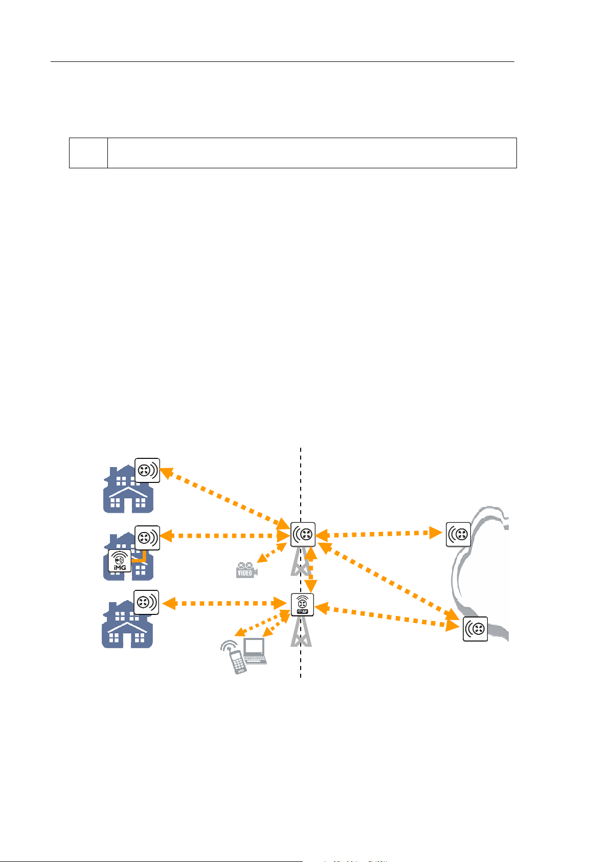
Thank you for purchasing an AT-WR4500 series Wireless Router.
The WR4500 family of dual band outdoor wireless base routers and routing CPEs allow the building of
wireless only or hybrid IP networks that are scalable, reliable and fully controllable.
Wireless ISPs can easily and quickly provide homes in rural areas with broadband Internet access and
VoIP telephony and, at the same time, can set-up WiFi hot spots for nomadic users.
Enterprises can connect remote buildings without the need for expensive leased lines and can extend
WiFi coverage to outdoor yards providing users with mobile intranet and Internet access everywhere.
Municipalities can build wireless IP networks for connecting remote offices and for increasing public safety
with real time monitored surveillance cameras and continuous communication with local police patrols.
Local utilities can easily control their remote equipments and read, in real time, gas, water and electricity
meters without any need for expensive fiber cabling.
Hot spot services can be provided to hotel guests and hospital patients ‘illuminating’ rooms from outside
the building with a reduced impact on medical equipments because no transmit radio will be installed
inside the hospital.
The single radio AT-WR4561 model can be used as either a base router, a hot spot or a wireless CPE
while the dual radio AT-WR4562 can be deployed at the same time as both a wireless only base router
and hot spot or base station in a Point to Multipoint configuration.
The AT-WR4542 with its embedded high gain antenna is best suited for being used as a wireless CPE
connecting to an AT-WR4561 or AT-WR4562 base router or can be deployed in couples for realizing
long reach high performances Point to Point links.
Flexibility is the primary advantage of the WR4500 family of wireless base routers. All products share the
same software and features and differ only in the number of radio interfaces.
Please refer to the ATWR45xx Quick Installation Guide for information on how to install connect and
initially setup each router model.
Access
5GHz
2.4GHz
2.4 / 5GHz
2.4GHz
Figure 1: AT-WR4500 Series typical application
Backbone
5GHz
IP Net
5GHz
Page 13

AT-WR4500 Series - IEEE 802.11abgh Outdoor Wireless Routers 13
RouterOS v3 Configuration and User Guide
1.1 Features
The AT-WR4500 series RouterOS firmware is very rich of features and very flexible. Among others:
• Real IP routing functionalities
• 2.4 GHz and 5 GHz dual band operations
• IEEE 802.11a/b/g/h compliant
• Certified for HiperLAN bands operation in Europe with DFS and TPC
• IEEE 802.3af compliant PoE powering
• IP66/67 rated outdoor robust construction
• Professional look suitable for indoor installation too
• Embedded IP firewalling functionalities
• Highly configurable QoS management for multimedia applications
• High sensitivity radio interface for longer reach and higher throughput on wireless links
• Wide choice of omnidirectional, directional and sector antennas
• RoHS compliant
1.2 Software License
RouterOS licensing scheme is based on software IDs. To license the software, you must know the
software ID that is displayed during installation process or can be read from the CLI system console or
WinBox. In order to get the software ID from system console, first log in (the default user is “admin”
with no password) and type: “/system license print”.
[admin@AT-WR4541g] > /system license print
software-id: "NCL8-3TT"
upgradable-to: v4.x
nlevel: 4
features:
[admin@AT-WR4541g] >
Page 14
14 AT-WR4500 Series - IEEE 802.11abgh Outdoor Wireless Routers
RouterOS v3 Configuration and User Guide
2 Configuring RouterOS
2.1 Logging in the AT-WR4500 Router
There are many options for accessing your AT-WR4500 Router command facility:
• Accessing the router Command Line Interface either via Telnet or SSH using any text-mode Telnet
or SSH client software
• Accessing the Web based Graphical User Interface via HTTP using a Web browser
• Running the MS Windows based WinBox graphical menu based configuration utility.
Every AT-WR4500 Wireless Router is factory configured with the static IP address 192.168.1.1/24 (net
mask 255.255.255.0) and both CLI and Web GUI can be accessed through this IP address.
2.2 Accessing the WR4500 through WinBox
Should the router come with a different IP address or if you do not want to change the IP address of
your PC or Workstation then it is possible to access the Router using the discovery facility of the
WinBox utility. Since WinBox can open a Layer 2 connection to the equipments, no change to the PC IP
address is needed. Please refer to the following section for instructions on how to get and use WinBox.
Downloading WinBox loader
The MS Windows based utility WinBox can be downloaded from the Allied Telesis web site accessing
http://www.alliedtelesis.com/. Select you country; access the “Software and Documentation” section
under the “Service/Support” menu; select “Wireless” in the “Product Category” drop down menu and
“AT-WR45421” in the “Product” drop down menu.
Scroll down the page and select the “AT-WR4500 WinBox loader” from the list of available Software.
Using WinBox
Connect the AT-WR4500 router with a LAN cable to your PC and launch the WinBox loader utility that
you have just downloaded.
Please make sure that the only LAN port enabled on your PC is the one connected to the WR4500
Router. Any other LAN port, either wired or wireless, shall be disabled.
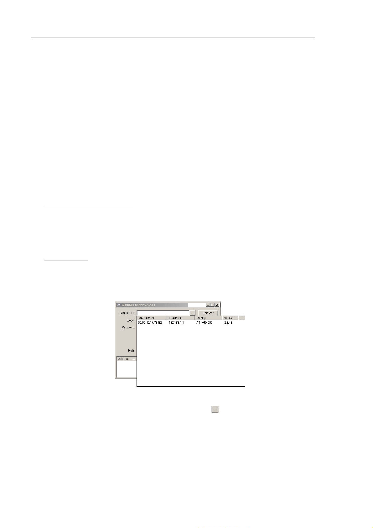
Figure 2: WinBox Loader discovering
When the WinBox loader startup window appears click on the button placed besides the “Connect
To:” field and wait for some seconds. A list of AT-WR4500 connected equipments (at least one) will
appear (see Figure 2). Select the one you want to access and then click on the “Connect” button. Every
AT-WR4500 router is configured in factory with “admin” as the login user with no password set.
The first time that you use it, the WinBox Loader will start downloading the rest of the WinBox
application from the WR4500 router. Wait up to one minute until the entire application has been
downloaded and the WinBox main window will appear.
Page 15
AT-WR4500 Series - IEEE 802.11abgh Outdoor Wireless Routers 15
RouterOS v3 Configuration and User Guide
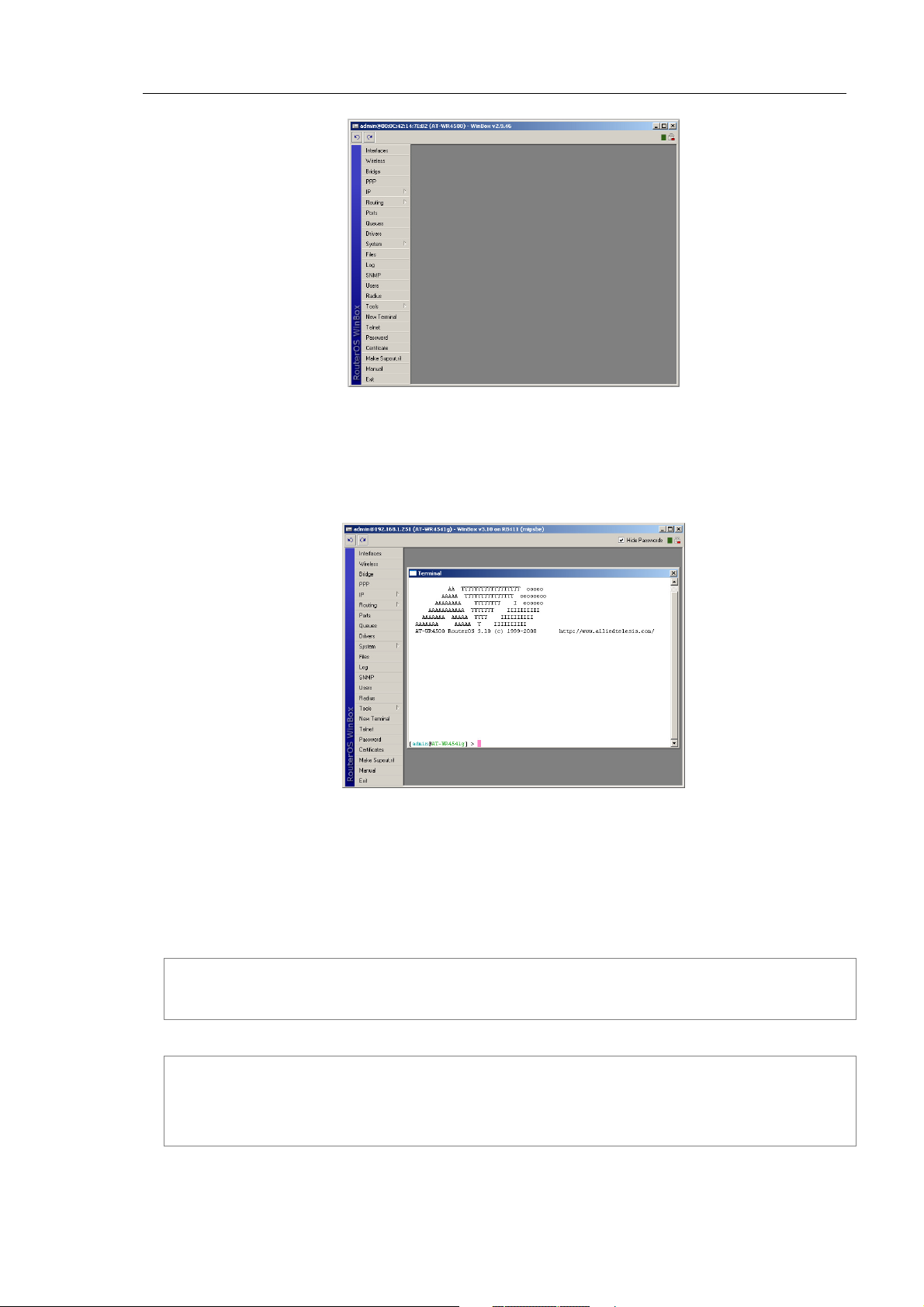
Figure 3: WinBox main window
Select from the menu bar located in the leftmost part of the window the command or menu that you
want to access and start configuring the equipment. For instance you can click on the “New Terminal”
button for opening a Telnet terminal window connected and logged into your router as shown in Figure
4.
Figure 4: WinBox with terminal window open
You can keep open as many WinBox internal windows as you need at the same time.
2.3 Accessing the CLI
When logging into the router via terminal console in telnet or SSH, you will be presented with the
RouterOS login prompt. Use 'admin' and no password (hit [Enter]) for logging into the router for the first
time
AT-WR4500 v3.0
Login: admin
Password:
The password can be changed with the /password command.
[admin@AT-WR4562] > password
old password:
new password: ************
retype new password: ************
[admin@AT-WR4562] >
Page 16

16 AT-WR4500 Series - IEEE 802.11abgh Outdoor Wireless Routers
RouterOS v3 Configuration and User Guide
After logging into the router you will be presented with the RouterOS™ Welcome Screen and command
prompt, for example:
AA TTTTTTTTTTTTTTTTTT ooooo
AAAAA TTTTTTTTTTTTTTT oooooooo
AAAAAAAA TTTTTTTT I oooooo
AAAAAAAAAAA TTTTTTT IIIIIIIIII
AAAAAAA AAAAA TTTT IIIIIIIIII
AAAAAAA AAAAA T IIIIIIIIII
AT-WR4500 RouterOS 3.10 (c) 1999-2008 http://www.alliedtelesis.com/
[admin@AT-WR4562] >
The command prompt shows the identity name of the router and the current menu level, for example:
[admin@AT-WR4562] >interface
[admin@AT-WR4562] interface>
[admin@AT-WR4562] >ip address
[admin@AT-WR4562] ip address>
The list of available commands at any menu level can be obtained by entering the question mark '?',
[admin@AT-WR4541g] > ?
blink --
certificate -- Certificate management
driver -- Driver management
file -- Local router file storage.
import --
interface -- Interface configuration
ip --
log -- System logs
password -- Change password
ping -- Send ICMP Echo packets
port -- Serial ports
ppp -- Point to Point Protocol
queue -- Bandwidth management
quit -- Quit console
radius -- Radius client settings
redo -- Redo previously undone action
routing --
setup -- Do basic setup of system
snmp -- SNMP settings
special-login -- Special login users
system -- System information and utilities
tool -- Diagnostics tools
undo -- Undo previous action
user --
export -- Print or save an export script that can be used to restore configuration
[admin@AT-WR4541g] >
The list of available commands and menus has short descriptions next to the items. You can move to the
desired menu level by typing its name and hitting the [Enter] key, for example:
[admin@AT-WR4562] > | Base level menu
[admin@AT-WR4562] > driver | Enter 'driver' to move to the driver
| level menu
[admin@AT-WR4562] driver> / | Enter '/' to move to the base level menu
| from any level
[admin@AT-WR4562] > interface | Enter 'interface' to move to the
| interface level menu
[admin@AT-WR4562] interface> /ip | Enter '/ip' to move to the IP level menu
| from any level
[admin@AT-WR4562] ip> |
Page 17

AT-WR4500 Series - IEEE 802.11abgh Outdoor Wireless Routers 17
RouterOS v3 Configuration and User Guide
A command or an argument does not need to be completed, if it is not ambiguous. For example, instead
of typing interface you can type just in or int. To complete a command use the [Tab] key.
The commands may be invoked from the menu level, where they are located, by typing its name. If the
command is in a different menu level than the current one, then the command should be invoked using its
full (absolute) or relative path, for example:
[admin@AT-WR4562] ip route> print | Prints the routing table
[admin@AT-WR4562] ip route> .. address print | Prints the IP address table
[admin@AT-WR4562] ip route> /ip address print | Prints the IP address table
The commands may have arguments. The arguments have their names and values. Some commands, may
have a required argument that has no name.
Command Action
command [Enter] Executes the command
[?] Shows the list of all available commands
command [?] Displays help on the command and the list of arguments
The completion is optional and you can just use short command and parameter names
command argument
[?]
[Tab]
/ Moves up to the base level
/command Executes the base level command
.. Moves up one level
"" Specifies an empty string
"word1 word2" Specifies a string of 2 words that contain a space
You can abbreviate names of levels, commands and arguments.
For the IP address configuration, instead of using the address and netmask arguments, in most cases you
can specify the address together with the number of true bits in the network mask, i.e., there is no need
to specify the netmask separately. Thus, the following two entries would be equivalent:
/ip address add address 10.0.0.1/24 interface ether1
/ip address add address 10.0.0.1 netmask 255.255.255.0 interface ether1
You must specify the size of the network mask in the address argument, even if it is the 32-bit subnet,
i.e., use 10.0.0.1/32 for address=10.0.0.1 netmask=255.255.255.255.
At the factory an IP address (192.168.1.1/24) is pre-configured to allow to use application such us
Telnet, WinBox or HTTP Web GUI, from the Ethernet interface ether1 connecting a PC configured with
an IP Address on the same IP subnet, i.e. 192.168.1.100/24. Whenever the AT-WR4500 will be reset
back the default setting, via the command /system reset-configuration, this IP address will not be
restored into the router running configuration. Connecting the console cable is possible to configure the IP
address using the commands reported here above.
Displays help on the command's argument
Completes the command/word. If the input is ambiguous, a second [Tab] gives
possible options
Page 18

18 AT-WR4500 Series - IEEE 802.11abgh Outdoor Wireless Routers
RouterOS v3 Configuration and User Guide
3 Configuration and Software Management
Document revision: 1.6 (Mon Sep 19 12:55:52 GMT 2005)
Applies to: V2.9
3.1 General Information
Summary
This chapter introduces you with commands which are used to perform the following functions:
• system backup
• system restore from a backup
• configuration export
• configuration import
• system configuration reset
Description
The configuration backup can be used for backing up RouterOS configuration to a binary file, which can
be stored on the router or downloaded from it using FTP for future use. The configuration restore can
be used for restoring the router's configuration, exactly as it was at the backup creation moment, from a
backup file. The restoration procedure (/system backup load) assumes the cofiguration is restored on
the same router, where the backup file was originally created (/system backup save), so it will create
partially broken configuration if the hardware has been changed.
The configuration export can be used for dumping out complete or partial RouterOS configuration to the
console screen or to a text (script) file, which can be downloaded from the router using FTP protocol.
The configuration dumped is actually a batch of commands that add (without removing the existing
configuration) the selected configuration to a router. The configuration import facility executes a batch of
console commands from a script file.
System reset command is used to erase all configuration on the router. Before doing that, it might be
useful to backup the router's configuration.
In order to be sure that the backup will not fail, system backup load command must be used on the
same computer with the same hardware where system backup save was done.
3.1.1 System Backup
Submenu level: /system backup
Description
The save command is used to store the entire router configuration in a backup file. The file is shown in
the /file submenu. It can be downloaded via ftp to keep it as a backup for your configuration.
To restore the system configuration, for example, after a /system reset, it is possible to upload that file
via ftp and load that backup file using load command in /system backup submenu.
Command Description
load name=[filename] - Load configuration backup from a file
save name=[filename] - Save configuration backup to a file
Example
To save the router configuration to file test:
[admin@AT-WR4562] system backup> save name=test
Configuration backup saved
[admin@AT-WR4562] system backup>
Page 19

AT-WR4500 Series - IEEE 802.11abgh Outdoor Wireless Routers 19
RouterOS v3 Configuration and User Guide
To see the files stored on the router:
[admin@AT-WR4562] > file print
# NAME TYPE SIZE CREATION-TIME
0 test.backup backup 12567 sep/08/2004 21:07:50
[admin@AT-WR4562] >
To load the saved backup file test:
[admin@AT-WR4562] system backup> load name=test
Restore and reboot? [y/N]:
Y
Restoring system configuration
System configuration restored, rebooting now
3.1.2 The Export Command
Command name: /export
Description
The export command prints a script that can be used to restore configuration. The command can be
invoked at any menu level, and it acts for that menu level and all menu levels below it. The output can be
saved into a file, available for download using FTP.
Command Description
file=[filename] - saves the export to a file
Example
[admin@AT-WR4562] > ip address print
Flags: X - disabled, I - invalid, D - dynamic
# ADDRESS NETWORK BROADCAST INTERFACE
0 10.1.0.172/24 10.1.0.0 10.1.0.255 bridge1
1 10.5.1.1/24 10.5.1.0 10.5.1.255 ether1
[admin@AT-WR4562] >
To make an export file:
[admin@AT-WR4562] ip address> export file=address
[admin@AT-WR4562] ip address>
To see the files stored on the router:
[admin@AT-WR4562] > file print
# NAME TYPE SIZE CREATION-TIME
0 address.rsc script 315 dec/23/2003 13:21:48
[admin@AT-WR4562] >
3.1.3 The Import Command
Command name: /import
Description
The root level command /import [file_name] executes a script, stored in the specified file adds the
configuration from the specified file to the existing setup. This file may contain any console comands,
including scripts. is used to restore configuration or part of it after a /system reset event or anything
that causes configuration data loss.
Page 20

20 AT-WR4500 Series - IEEE 802.11abgh Outdoor Wireless Routers
RouterOS v3 Configuration and User Guide
It is impossible to import the whole router configuration using this feature. It can only be used to import
a part of configuration (for example, firewall rules) in order to spare you some typing.
Command Description
file=[filename] - loads the exported configuration from a file to router
Example
To load the saved export file use the following command:
[admin@AT-WR4562] > import address.rsc
Opening script file address.rsc
Script file loaded successfully
[admin@AT-WR4562] >
3.1.4 Configuration Reset
Command name: /system reset
Description
The command clears all configuration of the router and sets it to the default including the login name and
password ('admin' and no password), IP addresses and other configuration is erased, interfaces will
become disabled. After the reset command router will reboot.
Command Description
reset - erases router's configuration
Example
If the router has been installed using netinstall and had a script specified as the initial configuration, the
reset command executes this script after purging the configuration. To stop it doing so, you will have to
reinstall the router.
[admin@AT-WR4562] > system reset
Dangerous! Reset anyway? [y/N]: n
action cancelled
[admin@AT-WR4562] >
3.2 Software Version Management
Document revision: 1.4 (Tue Oct 18 12:24:57 GMT 2005)
Applies to: V2.9
3.2.1 General Information
Summary
To upgrade RouterOS to a more recent version, you can simply transfer the packages to router via ftp,
using the binary transfer mode, and then just rebooting the router.
This manual discusses a more advanced method how to upgrade a router automatically. If you have more
than one router then this can be useful.
Specifications
Packages required: system
License required: Level1
Submenu level: /system upgrade
Page 21

AT-WR4500 Series - IEEE 802.11abgh Outdoor Wireless Routers 21
RouterOS v3 Configuration and User Guide
Standards and Technologies: None
Hardware usage: Not significant
3.2.2 System Upgrade
Submenu level: /system upgrade
Description
This submenu gives you the ability to download RouterOS software packages from a remote RouterOS
router.
Step-by-Step
Upload desired RouterOS packages to a router (not the one that you will upgrade).
Add this router's IP address, user name and password to /system upgrade upgrade-package-source
on the router(s) you will be upgrading. This step will only be needed once, and you may continue using
the same package source in future to upgrade the router(s) again. See the next section for details.
Refresh available software package list /system upgrade refresh
See available packages, using /system upgrade print command
Download selected or all packages from the remote router, using the download or download-all
command
Property Description
name (read-only: name) - package name
source (read-only: IP address) - source IP address of the router from which the package list entry is
retrieved
status (read-only: available | scheduled | downloading | downloaded | installed) - package status
version (read-only: text) - version of the package
Command Description
download - download packages from list by specifying their numbers
download-all - download all packages that are needed for the upgrade (packages which are listed in the
/system package print command output)
refresh - updates currently available package list
Example
See the available packages:
[admin@AT-WR4562] system upgrade> refresh
[admin@AT-WR4562] system upgrade> print
# SOURCE NAME VERSION STATUS COMPLETED
0 192.168.25.8 routeros-x86 2.9.44 available
1 192.168.25.8 routeros-rb500 3.0 available
[admin@AT-WR4562] system upgrade>
To upgrade chosen packages:
[admin@AT-WR4562] system upgrade> download 1
[admin@AT-WR4562] system upgrade> print
# SOURCE NAME VERSION STATUS COMPLETED
0 192.168.25.8 routeros-x86 2.9.44 available
1 192.168.25.8 routeros-rb500 3.0 available
[admin@AT-WR4562] system upgrade>
Page 22

22 AT-WR4500 Series - IEEE 802.11abgh Outdoor Wireless Routers
RouterOS v3 Configuration and User Guide
3.2.3 Adding Package Source
Submenu level: /system upgrade upgrade-package-source
Description
In this submenu you can add remote routers from which to download RouterOS software packages.
Property Description
address (IP address) - source IP address of the router from which the package list entry will be retrieved
password (text) - password of the remote router
user (text) - username of the remote router
Example
To add a router, with username admin and no password, from which the packages will be retrieved:
[admin@AT-WR4562] system upgrade upgrade-package-source> add \
\... address=192.168.25.8 user=admin
password:
[admin@AT-WR4562] ystem upgrade upgrade-package-source> print
# ADDRESS USER
0 192.168.25.8 admin
[admin@AT-WR4562] system upgrade upgrade-package-source>
After specifying a remote router in '/system upgrade upgrade-package-source', you can type '/system
upgrade refresh' to refresh the package list and '/system upgrade print' to see all available packages.
3.3 Software Package Management
Document revision: 1.3 (Mon Jul 11 12:42:44 GMT 2005)
Applies to: V2.9
3.3.1 General Information
Summary
The RouterOS is distributed in the form of software packages. The basic functionality of the router and
the operating system itself is provided by the system software package. Other packages contain
additional software features as well as support to various network interface cards.
Specifications
License required: Level1
Submenu level: /system package
Standards and Technologies: FTP
Hardware usage: Not significant
Description
Features
The modular software package system of RouterOS has the following features:
• Ability to extend RouterOS functions by installing additional software packages
• Optimal usage of the storage space by employing modular/compressed system
• Unused software packages can be uninstalled
• The RouterOS functions and the system itself can be easily upgraded
• Multiple packages can be installed at once
Page 23

AT-WR4500 Series - IEEE 802.11abgh Outdoor Wireless Routers 23
RouterOS v3 Configuration and User Guide
• The package dependency is checked before installing a software package. The package will not be
installed, if the required software package is missing
• The version of the feature package should be the same as that of the system package
• The packages can be uploaded on the router using ftp and installed only when the router is going for
shutdown during the reboot process
• If the software package file can be uploaded to the router, then the disk space is sufficient for the
installation of the package
• The system can be downgraded to an older version by uploading the needed packages to router via
FTP binary mode. After that, execute command /system package downgrade
3.3.2 Installation (Upgrade)
Description
Installation or upgrade of the RouterOS software packages can be done by uploading the newer version
of the software package to the router and rebooting it.
The software package files are compressed binary files, which can be downloaded from Allied Telesis web
site in th support section http://www.alliedtelesis.com/support/. The full name of the software package
consists of a descriptive name, version number and extension .npk, e.g. system-3.2.npk, routerboard-
3.2.npk. Package routeros-x86 contains all necessary packages for RouterOS installation and upgrading
for AT-WR456x Wireless Routers.
You should check the available hard disk space prior to downloading the package file by issuing /system
resource print command. If there is not enough free disk space for storing the upgrade packages, it can
be freed up by uninstalling some software packages, which provide functionality not required for your
needs. If you have a sufficient amount of free space for storing the upgrade packages, connect to the
router using ftp. Use user name and password of a user with full access privileges.
Step-by-Step
• Connect to the router using ftp client
• Select the BINARY mode file transfer
• Upload the software package files to the router
• Check the information about the uploaded software packages using the /file print command
• Reboot the router by issuing the /system reboot command or by pressing Ctrl+Alt+Del keys at the
router's console
• After reboot, verify that the packages were installed correctly by issuing /system package print
command
The packages uploaded to the router should retain the original name and also be in lowercase.
The installation/upgrade process is shown on the console screen (monitor) attached to the router.
Before upgrading the router, please check the current version of the system package and the additional
software packages. The versions of additional packages should match the version number of the system
software package.
The version of the RouterOS system software (and the build number) are shown before the console login
prompt. Information about the version numbers and build time of the installed RouterOS software
packages can be obtained using the /system package print command.
3.3.3 Uninstallation
Command name: /system package uninstall
Description
Usually, you do not need to uninstall software packages. However, if you have installed a wrong package,
or you need additional free space to install a new one, you have to uninstall some unused packages.
Page 24

24 AT-WR4500 Series - IEEE 802.11abgh Outdoor Wireless Routers
RouterOS v3 Configuration and User Guide
If a package is marked for uninstallation, but it is required for another (dependent) package, then the
marked package cannot be uninstalled. You should uninstall the dependent package too. For the list of
package dependencies see the 'Software Package List; section below. The system package will not be
uninstalled even if marked for uninstallation.
Example
Suppose we need to uninstall security package from the router:
[admin@AT-WR4562] system package> print
Flags: X - disabled
# NAME VERSION SCHEDULED
0 routeros-rb500 3.0
1 system 3.0
2 X ipv6 3.0
3 ntp 3.0
4 wireless 3.0
5 dhcp 3.0
6 routing 3.0
7 routerboard 3.0
8 advanced-tools 3.0
9 hotspot 3.0
10 ppp 3.0
11 security 3.0
[admin@AT-WR4562] system package> uninstall security
[admin@AT-WR4562] > .. reboot
3.3.4 Downgrading
Command name: /system package downgrade
Description
Downgrade option allows you to downgrade the software via FTP without losing your license key or
reinstalling the router. It is not recommended to use older versions, however, if the newest version
introduced some unwanted behavior, you may try to downgrade. If you send a support question, you will
probably be asked to upgrade to the latest version.
Step-by-Step
• Connect to the router using ftp client
• Select the BINARY mode file transfer
• Upload the software package files to the router
• Check the information about the uploaded software packages using the /file print command
• Execute command /system package downgrade. The router will downgrade and reboot.
• After reboot, verify that the packages were installed correctly by issuing /system package print
command
Command Description
downgrade - this command asks your confirmation and reboots the router. After reboot the software is
downgraded (if all needed packages were uploaded to the router)
Page 25

AT-WR4500 Series - IEEE 802.11abgh Outdoor Wireless Routers 25
RouterOS v3 Configuration and User Guide
Example
To downgrade the RouterOS (assuming that all needed packages are already uploaded):
[admin@AT-WR4562] system package> downgrade
Router will be rebooted. Continue? [y/N]:
y
system will reboot shortly
3.3.5 Disabling and Enabling
Specifications
Command name: /system package disable, /system package enable
Description
You can disable packages making them invisible for the system and later enable them, bringing the system
back to the previous state. It is useful if you don't want to uninstall a package, but just turn off its
functionality. This will save the RAM and processor resources for other applications, but will not free the
diskspace used by the package files.
If a package is marked for disabling, but it is required for another (dependent) package, then the
marked package cannot be disabled. You should disable or uninstall the dependent package too. For the
list of package dependencies see the 'Software Package List; section below.
If any of the test packages will be enabled (for example wireless-test and routing-test packages, that are
included in routeros-x86.npk) system automaticly will disable regular packages that conflict with them.
Example
Suppose we need to test ipv6 package features:
[admin@AT-WR4562] system package> print
Flags: X – disabled
# NAME VERSION SCHEDULED
0 routeros-rb500 3.0
1 system 3.0
2 X ipv6 3.0
3 ntp 3.0
4 wireless 3.0
5 dhcp 3.0
6 routing 3.0
7 routerboard 3.0
8 advanced-tools 3.0
9 hotspot 3.0
10 ppp 3.0
11 security 3.0
[admin@AT-WR4562] system package> enable ipv6
[admin@AT-WR4562] system package> .. reboot
3.3.6 Unscheduling
Command name: /system package unschedule
Description
Unschedule option allows to cancel pending uninstall, disable or enable actions for listed packages.
Packages marked for uninstallation, disabling or enabling on reboot in column "schedule" will have a
note, warning about changes.
Page 26

26 AT-WR4500 Series - IEEE 802.11abgh Outdoor Wireless Routers
RouterOS v3 Configuration and User Guide
Example
Suppose we need to cancel security package uninstallation action scheduled on reboot:
[admin@AT-WR4562] system package> print
Flags: X – disabled
# NAME VERSION SCHEDULED
0 routeros-rb500 3.0
1 system 3.0
2 X ipv6 3.0
3 ntp 3.0
4 wireless 3.0
5 dhcp 3.0
6 routing 3.0
7 routerboard 3.0
8 advanced-tools 3.0
9 hotspot 3.0
10 ppp 3.0
11 security 3.0 scheduled for uninstall
[admin@AT-WR4562] system package> unschedule security
[admin@AT-WR4562] system package>
3.3.7 System Upgrade
Submenu level: /system upgrade
Description
This submenu gives you the ability to download RouterOS software packages from a remote RouterOS
router.
Step-by-Step
• Upload desired RouterOS packages to a router (not the one that you will upgrade).
• Add this router's IP address, user name and password to /system upgrade upgrade-package-
source on the router(s) you will be upgrading. This step will only be needed once, and you may
continue using the same package source in future to upgrade the router(s) again. See the next section
for details.
• Refresh available software package list /system upgrade refresh
• See available packages, using /system upgrade print command
• Download selected or all packages from the remote router, using the download or download-all
• command
Property Description
name (read-only: name) - package name
source (read-only: IP address) - source IP address of the router from which the package list entry is
retrieved
status (read-only: available | scheduled | downloading | downloaded | installed) - package status
version (read-only: text) - version of the package
Command Description
download - download packages from list by specifying their numbers
download-all - download all packages that are needed for the upgrade (packages which are listed in the
/system package print command output)
refresh - updates currently available package list
Page 27

AT-WR4500 Series - IEEE 802.11abgh Outdoor Wireless Routers 27
RouterOS v3 Configuration and User Guide
Example
See the available packages:
[admin@AT-WR4562] system upgrade> refresh
[admin@AT-WR4562] system upgrade> print
# SOURCE NAME VERSION STATUS COMPLETED
0 192.168.25.8 routeros-x86 2.9.44 available
1 192.168.25.8 routeros-rb500 3.0 available
[admin@AT-WR4562] system upgrade>
To upgrade selected packages:
[admin@AT-WR4562] system upgrade> download 1
[admin@AT-WR4562] system upgrade> print
# SOURCE NAME VERSION STATUS COMPLETED
0 192.168.25.8 routeros-x86 2.9.44 available
1 192.168.25.8 routeros-rb500 3.0 downloading 16 %
[admin@AT-WR4562] system upgrade>
3.3.8 Adding Package Source
Submenu level: /system upgrade upgrade-package-source
Description
In this submenu you can add remote routers from which to download the RouterOS software packages.
Property Description
address (IP address) - source IP address of the router from which the package list entry will be retrieved
password (text) - password of the remote router
user (text) - username of the remote router
After specifying a remote router in /system upgrade upgrade-package-source, you can type
/system upgrade refresh to refresh the package list and /system upgrade print to see all available
packages.
Example
To add a router with IP address 192.168.25.8, username admin and no password:
[admin@AT-WR4562] system upgrade upgrade-package-source> add \
\... address=192.168.25.8 user=admin
password:
[admin@-WR4500] system upgrade upgrade-package-source> print
# ADDRESS USER
0 192.168.25.8 admin
[admin@AT-WR4562] system upgrade upgrade-package-source>
3.3.9 Software Package List
Description
System Software Package
The system software package provides the basic functionality of the RouterOS, namely:
• IP address management, ARP, static IP routing, policy routing, firewall (packet filtering, content
• filtering,masquerading, and static NAT), traffic shaping (queues), IP traffic accounting, Neighbour
• Discovery, IP Packet Packing, DNS client settings, IP service (servers)
Page 28

28 AT-WR4500 Series - IEEE 802.11abgh Outdoor Wireless Routers
RouterOS v3 Configuration and User Guide
• Ethernet interface support
• IP over IP tunnel interface support
• Ethernet over IP tunnel interface support
• driver management for Ethernet ISA cards
• serial port management
• local user management
• export and import of router configuration scripts
• backup and restore of the router's configuration
• undo and redo of configuration changes
• network diagnostics tools (ping, traceroute, bandwidth tester, traffic monitor)
• bridge support
• system resource management
• package management
• telnet client and server
• local and remote logging facility
• winbox server as well as winbox executable with some plugins
Additional Software Feature Packages
The table below shows additional software feature packages, extended functionality provided by them,
the required prerequisites and additional licenses, if any.
Allied Telesis distributes and supports the following packages only.
Package name Contents Prerequisites
advanced-tools
email client, pingers,
netwatch and other utilities
none none
Additional License
Call Content Connection
calea
(CCC) data retention server
for CALEA compliance
(Communications Assistance
none
none
for Law Enforcement Act)
dhcp
DHCP server and client
support
none
none
hotspot HotSpot gateway none any additional license
ntp
ppp
routerboard
network time protocol
support
support for PPP, PPTP,
L2TP, PPPoE and ISDN PPP
support for RouterBoardspecific functions and utilities
none none
none none
none none
routing support for RIP and OSPF none none
security
user-manager embedded RADIUS server
support for IPSEC, SSH and
secure WinBox connections
none none
none none
with web interface
Page 29

AT-WR4500 Series - IEEE 802.11abgh Outdoor Wireless Routers 29
RouterOS v3 Configuration and User Guide
Package name Contents Prerequisites Additional License
Support for wireless
wireless
interfaces with updated
Country Regulatory Domain
settings
none None
Page 30

30 AT-WR4500 Series - IEEE 802.11abgh Outdoor Wireless Routers
RouterOS v3 Configuration and User Guide
4 Configuring Interfaces
4.1 General Interface Settings
Document revision: 1.1 (Fri Mar 05 08:08:52 GMT 2004)
Applies to: V2.9
4.1.1 General Information
Summary
AT-WR4500 RouterOS supports a variety of physical and virtual interfaces (like Bonding, Bridge, VLAN
etc.). Each of them has its own submenu, but there is also a list of all interfaces where some common
properties can be configured.
Description
The Manual describes general settings of RouterOS interfaces.
4.1.2 Interface Status
Submenu level: /interface
Property Description
mtu (integer) - maximum transmission unit for the interface (in bytes)
name (text) - the name of the interface
type (read-only: arlan | bonding | bridge | cyclades | eoip | ethernet | farsync | ipip | isdn-client |
isdn-server | l2tp-client | l2tp-server | moxa-c101 | moxa-c502 | mtsync | pc | ppp-client | ppp-server |
pppoe-client | pppoe-server | pptp-client | pptp-server | pvc | radiolan | sbe | vlan | wavelan | wireless| xpeed) -
interface type
Example
To see the list of all available interfaces:
[admin@AT-WR4562] interface> print
Flags: X - disabled, D - dynamic, R - running
# NAME TYPE RX-RATE TX-RATE MTU
0 R ether1 ether 0 0 1500
1 R bridge1 bridge 0 0 1500
2 R ether2 ether 0 0 1500
3 R wlan1 wlan 0 0 1500
[admin@AT-WR4562] interface>
4.1.3 Traffic Monitoring
Command name: /interface monitor-traffic
Description
The traffic passing through any interface can be monitored.
Property Description
received-bits-per-second (read-only: integer) - number of bits that interface has received in one
second
received-packets-per-second (read-only: integer) - number of packets that interface has received
in one second
sent-bits-per-second (read-only: integer) - number of bits that interface has sent in one second
sent-packets-per-second (read-only: integer) - number of packets that interface has sent in one second
Page 31

AT-WR4500 Series - IEEE 802.11abgh Outdoor Wireless Routers 31
RouterOS v3 Configuration and User Guide
One or more interfaces can be monitored at the same time.
To see overall traffic passing through all interfaces at time, use aggregate instead of interface name.
Example
Multiple interface monitoring:
/interface monitor-traffic ether1,aggregate
received-packets-per-second: 9 11
received-bits-per-second: 4.39kbps 6.19kbps
sent-packets-per-second: 16 17
sent-bits-per-second: 101kbps 101kbps
[Q quit|D dump|C-z pause]
4.2 Ethernet Interfaces
Document revision: 1.2 (Fri Apr 16 12:35:37 GMT 2004)
Applies to: V2.9
4.2.1 General Information
Summary
RouterOS supports various types of Ethernet Interfaces with all available features. This section describes
how to configure the various parameters and settings.
Specifications
Packages required: system
License required: Level1
Submenu level: /interface ethernet
Standards and Technologies: IEEE 802.3
Hardware usage: Not significant
Related Topics
• Software Package Management
• IP Addresses and ARP
• DHCP and DNS
Additional Resources
• http://grouper.ieee.org/groups/802/3/
• http://en.wikipedia.org/wiki/IEEE_802.3
• http://www.ethermanage.com/ethernet/ethernet.html
• http://www.dcs.gla.ac.uk/~liddellj/nct/ethernet_protocol.html
4.2.2 Ethernet Interface Configuration
Submenu level: /interface ethernet
Property Description
arp (disabled | enabled | proxy-arp | reply-only; default: enabled) - Address Resolution Protocol
auto-negotiation (yes | no; default: yes) - when enabled, the interface "advertises" its maximum
capabilities to achieve the best connection possible to NS DP83815/6 cards)
Page 32

32 AT-WR4500 Series - IEEE 802.11abgh Outdoor Wireless Routers
RouterOS v3 Configuration and User Guide
default - suport long cables
short - support short cables
standard - same as default
disable-running-check (yes | no; default: yes) - disable running check. If this value is set to 'no', the
router automatically detects whether the NIC is connected with a device in the network or not
full-duplex (yes | no; default: yes) - defines whether the transmission of data appears in two directions
simultaneously
mac-address (MAC address) - set the Media Access Control number of the card
mdix-enable (yes | no) - whether the MDI/X auto crosscable correction feature is enabled for the port
(if applicable)
mtu (integer; default: 1500) - Maximum Transmission Unit
name (name; default: etherN) - assigned interface name, whrere 'N' is the number of the ethernet
interface
speed (10 Mbps | 100 Mbps | 1 Gbps) - sets the data transmission speed of the interface. By default, this
value is the maximal data rate supported by the interface
When disable-running-check is set to no, the router automatically detects whether the NIC is
connected to a device in the network or not. When the remote device is not connected (the leds are not
blinking), the route which is set on the specific interface, becomes invalid.
Command Description
reset-mac (name) - set the MAC address of the NIC to the factory default setting
Example
[admin@AT-WR4562] > interface print
Flags: X - disabled, D - dynamic, R - running
# NAME TYPE RX-RATE TX-RATE MTU
0 X ether1 ether 0 0 1500
[admin@AT-WR4562] > interface enable ether1
[admin@AT-WR4562] > interface print
Flags: X - disabled, D - dynamic, R - running
# NAME TYPE RX-RATE TX-RATE MTU
0 R ether1 ether 0 0 1500
[admin@AT-WR4562] > interface ethernet
[admin@AT-WR4562] interface ethernet> print
Flags: X - disabled, R - running
# NAME MTU MAC-ADDRESS ARP
0 R ether1 1500 00:0C:42:03:00:F2 enabled
[admin@AT-WR4562] interface ethernet> print detail
Flags: X - disabled, R - running
0 R name="ether1" mtu=1500 mac-address=00:0C:42:03:00:F2 arp=enabled
disable-running-check=yes auto-negotiation=yes full-duplex=yes
cable-settings=default speed=100Mbps
[admin@AT-WR4562] interface ethernet>
4.2.3 Monitoring the Interface Status
Command name: /interface ethernet monitor
Property Description
auto-negotiation (done | incomplete) - fast link pulses (FLP) to the adjacent link station to negotiate the
SPEED and MODE of the link. Both stations choose the maximal speed boh support.
done - negotiation done
incomplete - negotiation failed
default-cable-setting (read-only: short | standard) - default cable length setting (only applicable to NS
DP83815/6 cards)
short - support short cables
standard - same as default
Page 33

AT-WR4500 Series - IEEE 802.11abgh Outdoor Wireless Routers 33
2 . 2 ( T u e J u l 1 8 1 4 : 5 3 : 5 8 G M T 2 0 0 6
V 2 . 9
RouterOS v3 Configuration and User Guide
full-duplex (yes | no) - whether transmission of data occurs in two directions simultaneously
rate (10 Mbps | 100 Mbps | 1 Gbps) - the actual data rate of the connection
status (link-ok | no-link | unknown) - status of the interface, one of the:
link-ok - the card is connected to the network
no-link - the card is not connected to the network (cable is not plugged in or faulty)
unknown - the connection is not recognized (if the card does not report connection status)
See the IP Addresses and ARP section of the manual for information how to add IP addresses to the
interfaces.
Example
[admin@AT-WR4562] interface ethernet> monitor ether1,ether2
status: link-ok link-ok
auto-negotiation: done done
rate: 100Mbps 100Mbps
default-cable-setting: standard standard
4.2.4 Troubleshooting
Description
Interface monitor shows wrong information
In some very rare cases it is possible that the device driver does not show correct information, but it
does not affect the NIC's performance (of course, if your card is not broken)
4.3 Wireless Interfaces
D o c u m e n t r e v i s i o n :
A p p l i e s t o :
4.3.1 General Information
Summary
This manual discusses management of the Atheros chipset based wireless interfaces of the AT-WR4500
Series wireless routers that comply with IEEE 802.11 set of standards. These interfaces use radio waves
as a physical signal carrier and are capable of data transmission with speeds up to 108 Mbps (in 5GHz
turbo-mode).
RouterOS can operate wireless interfaces as wireless clients (station mode), wireless bridges (bridge
mode), wireless access points (ap-bridge mode), and for antenna positioning (alignment-only mode).
RouterOS provides a complete support for IEEE 802.11a, 802.11b and 802.11g wireless networking
standards. There are several additional features implemented for the wireless networking in RouterOS WPA (Wi-Fi Protected Access), WEP (Wired Equivalent Privacy), software and hardware AES
encryption, WDS (Wireless Distribution System), DFS (Dynamic Frequency Selection), Alignment mode
(for positioning antennas and monitoring wireless signal), VAP (Virtual Access Point), ability to disable
packet forwarding among clients, Nstreme wireless transmission protocol and others.
The Nstreme protocol is proprietary (i.e., incompatible with other vendors) wireless protocol aimed to
improve point-to-point and point-to-multipoint wireless links. Advanced version of Nstreme, called
Nstreme2 works with a pair of wireless interfaces (Atheros AR5210 and newer MAC chips only) - one
for transmitting data and one for receiving.
Benefits of Nstreme protocol:
• Client polling. Polling reduces media access times, because the card does not need to ensure the air
is "free" each time it needs to transmit data (the polling mechanism takes care of it)
• Very low protocol overhead per frame allowing super-high data rates
Page 34

34 AT-WR4500 Series - IEEE 802.11abgh Outdoor Wireless Routers
RouterOS v3 Configuration and User Guide
• No implied protocol limits on link distance
• No implied protocol speed degradation for long link distances
• Dynamic protocol adjustment depending on traffic type and resource usage
Quick Setup Guide
Let's consider that you have a wireless interface, called wlan1.
To set it as an Access Point, working in 802.11g standard, using frequency 2442 MHz and Service Set
Identifier test, do the following configuration:
/interface wireless set wlan1 ssid=test frequency=2442 band=2.4ghz-b/g \
mode=ap-bridge disabled=no
Now your router is ready to accept wireless clients.
To make a point-to-point connection, using 802.11a standard, frequency 5805 MHz and Service Set
Identifier p2p, write:
/interface wireless set wlan1 ssid="p2p" frequency=5805 band=5ghz \
mode=bridge disabled=no
The remote interface should be configured to station as showed below.
To make the wireless interface as a wireless station, working in 802.11a standard and Service Set
Identifier p2p:
/interface wireless set wlan1 ssid="p2p" band=5ghz mode=station disabled=no
Specifications
Packages required: wireless
License required: Level4 (station and bridge mode)
Submenu level: /interface wireless
Standards and Technologies: IEEE802.11a, IEEE802.11b, IEEE802.11g
Hardware usage: Not significant
Related Topics
• IP Addresses and ARP
• Log Management
Description
The Atheros card has been tested for distances up to 20 km providing connection speed up to 17Mbit/s.
With appropriate antennas and cabling the maximum distance should be as far as 50 km.
These values of ack-timeout were approximated from the tests done by us, as well as by some of our
customers:
range
0km default default default
ack-timeout
5GHz 5GHz-turbo 2.4GHz-G
5km 52 30 62
10km 85 48 96
15km 121 67 133
20km 160 89 174
25km 203 111 219
Page 35

AT-WR4500 Series - IEEE 802.11abgh Outdoor Wireless Routers 35
RouterOS v3 Configuration and User Guide
range
30km 249 137 368
35km 298 168 320
40km 350 190 375
45km 405 - -
You can also use dynamic ack-timeout value - the router will determine ack-timeout setting
automatically by sending periodically packets with a different ack-timeout. Ack-timeout values by which
ACK frame was received are saved and used later to determine the real ack-timeout.
The Nstreme protocol may be operated in three modes:
• Point-to-Point mode - controlled point-to-point mode with one radio on each side
• Dual radio Point-to-Point mode (Nstreme2) - the protocol will use two radios on both sides
• Point-to-Multipoint - controlled point-to-multipoint mode with client polling (like AP-controlled
•
These are not the precise values. Depending on hardware used and many other factors they may vary
up to +/- 15 microseconds.
simultaneously (one for transmitting data and one for receiving), allowing superfast point-to-point
connection
TokenRing)
ack-timeout
5GHz 5GHz-turbo 2.4GHz-G
4.3.2 Wireless Interface Configuration
Submenu level: /interface wireless
Description
In this section we will discuss the most important part of the configuration.
Property Description
ack-timeout (integer | dynamic | indoors) - acknowledgement code timeout (transmission acceptance
timeout) in microseconds for acknowledgement messages. Can be one of these:
dynamic - ack-timeout is chosen automatically
indoors - standard constant for indoor usage
adaptive-noise-immunity (yes | no; default: yes) - adjust various receiver parameters dynamically to
minimize interference and noise effect on the signal quality.
allow-sharedkey (yes | no; default: no) - allow WEP Shared Key cilents to connect. Note that no
authentication is done for these clients (WEP Shared keys are not compared to anything) - they are just
accepted at once (if access list allows that)
antenna-gain (integer; default: 0) - antenna gain in dBi. This parameter will be used to calculate whether
your system meets regulatory domain's requirements in your country
antenna-mode (ant-a | ant-b | rxa-txb | txa-rxb; default: ant-a) - which antenna to use for
transmit/receive data:
ant-a - use only antenna a
ant-b - use only antenna b
rxa-txb - use antenna a for receiving packets, use antenna b for transmitting packets
txa-rxb - use antenna a for transmitting packets, antenna b for receiving packets
area (text; default: "") - string value that is used to describe an Access Point. Connect List on the
Client's side comparing this string value with area-prefix string value makes decision whether allow a
Client connect to the AP. If area-prefix match the entire area string or only the beginning of it the
Client is allowed to connect to the AP
arp (disabled | enabled | proxy-arp | reply-only; default: enabled) - Address Resolution Protocol setting
Page 36

36 AT-WR4500 Series - IEEE 802.11abgh Outdoor Wireless Routers
RouterOS v3 Configuration and User Guide
band - operating band
2.4ghz-b - IEEE 802.11b
2.4ghz-b/g - IEEE 802.11g (supports also legacy IEEE 802.11b protocol)
2.4ghz-g-turbo - IEEE 802.11g using double channel, providing air rate of up to 108 Mbit
2.4ghz-onlyg - only IEEE 802.11g
5ghz - IEEE 802.11a up to 54 Mbit
5ghz-turbo - IEEE 802.11a using double channel, providing air rate of up to 108Mbit
2ghz-10mhz - variation of IEEE 802.11g with half the band, and, accordingly, twice lower speed (air rate
of up to 27Mbit)
2ghz-5mhz - variation of IEEE 802.11g with quarter the band, and, accordingly, four times lower speed
(air rate of up to 13.5Mbit)
5ghz-10mhz - variation of IEEE 802.11a with half the band, and, accordingly, twice lower speed (air rate
of up to 27Mbit)
5ghz-5mhz - variation of IEEE 802.11a with quarter the band, and, accordingly, four times lower speed
(air rate of up to 13.5Mbit)
basic-rates-a/g (multiple choice: 6Mbps, 9Mbps, 12Mbps, 18Mbps, 24Mbps, 36Mbps, 48Mbps, 54Mbps;
default: 6Mbps) - basic rates in 802.11a or 802.11g standard. This should be the minimal speed all the
wireless network nodes support (they will not be ableto connect otherwise). It is recommended to leave
this as default
basic-rates-b (multiple choice: 1Mbps, 2Mbps, 5.5Mbps, 11Mbps; default: 1Mbps) - basic rates in 802.11b
mode. This should be the minimal speed all the wireless network nodes support (they will not be ableto
connect otherwise). It is recommended to leave this as default
burst-time (time; default: disabled) - time in microseconds which will be used to send data without
stopping. Note that no other wireless cards in that network will be able to transmit data during bursttime microseconds.
compression (yes | no; default: no) - if enabled on AP (in ap-bridge or bridge mode), it advertizes that it
is capable to use hardware data compression. If a client, connected to this AP, also supports and is
configured to use the hardware data compression, it requests the AP to use compression. This property
does not affect clients, which do not support compression.
country (albania | algeria | argentina | armenia | australia | austria | azerbaijan | bahrain | belarus | belgium
| belize | bolvia | brazil | brunei darussalam | bulgaria | canada | chile | china | colombia | costa rica | croatia
| cyprus | czech republic | denmark | dominican republic | ecuador | egypt | el salvador | estonia | finland |
france | france_res | georgia | germany | greece | guatemala | honduras | hong kong | hungary | iceland |
india | indonesia | iran | ireland | israel | italy | japan | japan1 | japan2 | japan3 | japan4 | japan5 | jordan |
kazakhstan | korea republic | korea republic2 | kuwait | latvia | lebanon | liechtenstein | lithuania |
luxemburg | macau | macedonia | malaysia | mexico | monaco | morocco | netherlands | new zealand |
no_country_set | north korea | norway | oman | pakistan | panama | peru | philippines | poland | portugal |
puerto rico | qatar | romania | russia | saudi arabia | singapore | slovak republic | slovenia | south africa |
spain | sweden | switzerland | syria | taiwan | thailand | trinidad & tobago | tunisia | turkey | ukraine |
united arab emirates | united kingdom | united states | uruguay | uzbekistan | venezuela | viet nam | yemen
| zimbabwe; default: no_country_set) - limits wireless settings (frequency and transmit power) to those
which are allowed in the respective country
no_country_set - no regulatory domain limitations
default-ap-tx-limit (integer; default: 0) - limits data rate for each wireless client (in bps)
0 - no limits
default-authentication (yes | no; default: yes) - specifies the default action on the client's side for APs
that are not in connect list or on the AP's side for clients that are not in access list
yes - enables AP to register a client if it is not in access list. In turn for client it allows to associate with
AP not listed in client's connect list
default-client-tx-limit (integer; default: 0) - limits each client's transmit data rate (in bps). Works only if
the client is also a Router
0 - no limits
default-forwarding (yes | no; default: yes) - whether to use data forwarding by default or not. If set to
'no', the registered clients will not be able to communicate with each other
dfs-mode (none | radar-detect | no-radar-detect; default: none) - used for APs to dynamically select
frequency at which this AP will operate
none - do not use DFS
no-radar-detect - AP scans channel list from "scan-list" and chooses the frequency which is with the
lowest amount of other networks detected
Page 37

AT-WR4500 Series - IEEE 802.11abgh Outdoor Wireless Routers 37
RouterOS v3 Configuration and User Guide
radar-detect - AP scans channel list from "scan-list" and chooses the frequency which is with the lowest
amount of other networks detected, if no radar is detected in this channel for 60 seconds, the AP starts
to operate at this channel, if radar is detected, the AP continues searching for the next available channel
which is with the lowest amount of other networks detected
disable-running-check (yes | no; default: no) - disable running check. If value is set to 'no', the router
determines whether the card is up and running - for AP one or more clients have to be registered to it,
for station, it should be connected to an AP. This setting affects the records in the routing table in a way
that there will be no route for the card that is not running (the same applies to dynamic routing
protocols). If set to 'yes', the interface will always be shown as running
disconnect-timeout (time; default: 3s) - time since the third sending failure ( 3*(hw-retries+1) packets
have been lost) at the lowest datarate only (i.e. since the first time on-fail-retry-time has been
activated), when the client gets disconnected (logged as "extensive data loss")
frame-lifetime (integer; default: 0) - frame lifetime in centiseconds since the first sending attempt to
send the frame. Wireless normally does not drop any packets at all until the client is disconnected. If
there is no need to accumulate packets, you can set the time after which the packet will be discarded
0 - never drop packets until the client is disconnected (default value)
frequency (integer) - operating frequency of the AP (ignored for the client, which always scans through
its scan list regardless of the value set in this field)
frequency-mode (regulatory-domain | manual-tx-power | superchannel; default: regulatory-domain) defines which frequency channels to allow
regulatory-domain - use the channels allowed in the selected country at the allowed transmit power
(with the configured antenna-gain deducted) only. Also note that in this mode card will never be
configured to higher power than allowed by the respective regulatory domain
manual-tx-power - use the channels allowed in the selected country only, but take transmit power
from the tx-power settings
superchannel - only possible with the Superchannel license. In this mode all hardware supported
channels and transmit power settings are allowed
hide-ssid (yes | no; default: no) - whether to hide ssid or not in the beacon frames:
yes - ssid is not included in the beacon frames. AP replies only to probe-requests with the given ssid
no - ssid is included in beacon frames. AP replies to probe-requests with the given ssid ant to 'broadcast
ssid' (empty ssid)
hw-retries (integer; default: 15) - number of frame sending retries until the transmission is considered
failed. Data rate is decreased upon failure, but if there is no lower rate, 3 sequential failures activate on-
fail-retry-time transmission pause and the counter restarts. The frame is being retransmitted either
until success or until client is disconnected
interface-type (read-only: text) - adapter type and model
mac-address (MAC address) - Media Access Control (MAC) address of the interface
master-interface (name) - physical wireless interface name that will be used by Virtual Access Point
(VAP) interface
max-station-count (integer: 1..2007; default: 2007) - maximal number of clients allowed to connect to
AP. Real life experiments (from our customers) show that 100 clients can work with one AP, using traffic
shaping
mode (alignment-only | ap-bridge | bridge | nstreme-dual-slave | station | station-pseudobridge | stationpseudobridge-clone | station-wds | wds-slave; default: station) - operating mode:
alignment-only - this mode is used for positioning antennas (to get the best direction)
ap-bridge - the interface is operating as an Access Point
bridge - the interface is operating as a bridge. This mode acts like ap-bridge with the only difference
being it allows only one client
nstreme-dual-slave - the interface is used for nstreme-dual mode
station - the interface is operating as a wireless station (client)
station-pseudobridge - wireless station that can be put in bridge. MAC NAT is performed on all traffic
sent over the wireless interface, so that it look like coming from the station's MAC address regardless of
the actual sender (the standard does not allow station to send packets with different MAC address from
its own). Reverse translation (when replies arrive from the AP to the pseudobridge station) is based on
the ARP table. Non-IP protocols are being sent to the default MAC address (the last MAC address, which
the station has received a non-IP packet from). That means that if there is more than one client that uses
non-IP protocols (for example, PPPoE) behind the station, none of them will be able to work correctly
station-pseudobridge-clone - similar to the station-pseudobridge, but the station will clone MAC
address of a particular device (set in the station-bridge-clone-mac property), i.e. it will change itsown
Page 38

38 AT-WR4500 Series - IEEE 802.11abgh Outdoor Wireless Routers
RouterOS v3 Configuration and User Guide
address to the one of a different device. In case no address is set in the station-bridge-clone-mac
property, the station postpones connecting to an AP until some packet, with the source MAC address
different from any of the router itself, needs to be transmitted over that interface. It then connects to an
AP with the MAC address of the device that have sent that packet
station-wds - the interface is working as a station, but can communicate with a WDS peer
wds-slave - the interface is working as it would work in ap-bridge mode, but it adapts to its WDS peer's
frequency if it is changed
mtu (integer: 68..1600; default: 1500) - Maximum Transmission Unit
name (name; default: wlanN) - assigned interface name
noise-floor-threshold (integer | default: -128..127; default: default) - noise strength in dBm below
which the card will transmit
on-fail-retry-time (time; default: 100ms) - time, after which we repeat to communicate with a wireless
device, if a data transmission has failed 3 times on the lowest rate
periodic-calibration (default | disabled | enabled; default: default) - to ensure performance of chipset
over temperature and environmental changes, the software performs periodic calibration
periodic-calibration-interval (integer; default: 60) - interfal between periodic recalibrations, in seconds
preamble-mode (both | long | short; default: both) - sets the synchronization field in a wireless packet
long - has a long synchronization field in a wireless packet (128 bits). Is compatible with 802.11 standard
short - has a short synchronization field in a wireless packet (56 bits). Is not compatible with 802.11
standard. With short preamble mode it is possible to get slightly higher data rates
both - supports both - short and long preamble
prism-cardtype (30mW | 100mW | 200mW) - specify the output of the Prism chipset based card
proprietary-extensions (pre-2.9.25 | post-2.9.25; default: post-2.9.25) - the method to insert
additional information (RouterOS proprietary extensions) into the wireless frames. This option is needed
to workaround incompatibility between the old (pre-2.9.25) method and new Intel Centrino PCI-Express
cards
pre-2.9.25 - include extensions in the form accepted by older RouterOS versions. This will include the
new format as well, so this mode is compatiblewith all RouterOS versions. This mode is incompatible
with wireless clients built on the new Centrino wireless chipset and may as well be incompatible with
some other stations
radio-name (text) - descriptive name of the card. Only for RouterOS devices
rate-set (default | configured) - which rate set to use:
default - basic and supported-rates settings are not used, instead default values are used
configured - basic and supported-rates settings are used as configured
scan-list (multiple choice: integer | default; default: default) - the list of channels to scan
default - represents all frequencies, allowed by the regulatory domain (in the respective country). If no
country is set, these frequencies are used - for 2.4GHz mode: 2412, 2417, 2422, 2427, 2432, 2437, 2442,
2447, 2452, 2457, 2462; for 2.4GHz-g-turbo mode: 2437; for 5GHz mode: 5180, 5200, 5220, 5240, 5260,
5280, 5300, 5320, 5745, 5765, 5785, 5805, 5825; for 5GHz-turbo: 5210, 5250, 5290, 5760, 5800
security-profile (text; default: default) - which security profile to use. Define security profiles under
/interface wireless security-profiles where you can setup WPA or WEP wireless security, for further details,
see the Security Profiles section of this manual
ssid (text; default: AT-WR4560) - Service Set Identifier. Used to separate wireless networks
supported-rates-a/g (multiple choice: 6Mbps, 9Mbps, 12Mbps, 18Mbps, 24Mbps, 36Mbps, 48Mbps,
54Mbps) - rates to be supported in 802.11a or 802.11g standard
supported-rates-b (multiple choice: 1Mbps, 2Mbps, 5.5Mbps, 11Mbps) - rates to be supported in 802.11b
standard
tx-power (integer: -30..30; default: 17) - manually sets the transmit power of the card (in dBm), if txpower-mode is set to card rates or all-rates-fixed (see tx-power-mode description below)
tx-power-mode (all-rates-fixed | card-rates | default | manual-table; default: default) - choose the
transmit power mode for the card:
all-rates-fixed - use one transmit power value for all rates, as configured in tx-power
card-rates - use transmit power, that for different rates is calculated according the cards transmit power
algorithm, which as an argument takes tx-power value
default - use the default tx-power
manual-table - use the transmit powers as defined in /interface wireless manual-tx-power-table
update-stats-interval (time) - how often to update (request from the clients) signal strength and ccq
values in /interface wireless registration-table
Page 39

AT-WR4500 Series - IEEE 802.11abgh Outdoor Wireless Routers 39
he IEEE 802.11 standard limitation makes it impossible for wireless interfaces in station mode to work
as expected when bridged. That means that if you need to create a bridge, you should not use station
mode (may
, the router determines whether the network interface is
for AP, one or more clients have to be registered to it, for
), its route in the
power that the card can use. If you want to use larger
! Usually, you can use this parameter to
power controlling properties should be left at the default settings. Changing the default
, but without testing, the most common result is
degradation of range and throughput. Some of the problems that may occur are: (1) overheating of the
power amplifier chip and the card which will cause lower efficiency and more data errors; (2) overdriving
the amplifier which will cause more data errors; (3) excessive power usage for the card and this may
overload the 3.3V power supply of the board that the card is located on resulting in voltage drop and
RouterOS v3 Configuration and User Guide
wds-cost-range (integer; default: 50-150) - range, within which the bridge port cost of the WDS links
are adjusted. The calculations are based on the p-throughput value of the respective WDS interface,
which represents estimated approimate rhtoughput on the interface, which is mapped on the wds-cost-
range scale so that bigger p-throughput would correspond to numerically lower port cost. The cost is
recalculated every 20 seconds or when the p-throughput changes more than by 10% since the last
recalculation
wds-default-bridge (name; default: none) - the default bridge for WDS interface. If you use dynamic
WDS then it is very useful in cases when wds connection is reset - the newly created dynamic WDS
interface will be put in this bridge
wds-default-cost (integer; default: 100) - default bridge port cost of the WDS links
wds-ignore-ssid (yes | no; default: no) - if set to 'yes', the AP will create WDS links with any other AP
in this frequency. If set to 'no' the ssid values must match on both APs
wds-mode (disabled | dynamic | static) - WDS mode:
disabled - WDS interfaces are disabled
dynamic - WDS interfaces are created 'on the fly'
static - WDS interfaces are created manually
wmm-support (disabled | enabled | required) - whether to allow (or require) peer to use WMM
extensions to provide basic quality of service
T
mode on that machine. In case you need a bridge on a wireless station, use station-wds
only be used in the AP supports WDS). Bridging on the AP side works fine.
It is strongly suggested to leave basic rates at the lowest setting possible.
Using compression, the AP can serve approximately 50 clients with compression enabled!
Compression is supported only by Atheros wireless interfaces like the ones used in AT-WR4500 series.
If disable-running-check value is set to no
up and running - in order to show flag R
station, it should be connected to an AP. If the interface does not appear as running (R
routing table is shown as invalid! If set to yes, the interface will always be shown as running.
On Atheros-based interfaces, encryption (WEP, WPA, etc.) does not work when compression is enabled.
The tx-power default setting is the maximum txtx-rates, you are able to set them, but do it at your own risk
reduce the tx-power.
In general txsetting may help with some interfaces in some situations
reboot or excessive temperatures for the board.
If the wireless interfaces are put in nstreme-dual-slave mode, all configuration will take place in
/interface wireless nstreme-dual submenu, described further on in this manual. In that case,
configuration made in this submenu will be partially ignored. WDS cannot be used together with the
Nstreme-dual.
Example
This example shows how configure a wireless client.
Page 40

40 AT-WR4500 Series - IEEE 802.11abgh Outdoor Wireless Routers
RouterOS v3 Configuration and User Guide
To see current interface settings:
[admin@AT-WR4562] interface wireless> print
Flags: X - disabled, R - running
Flags: X - disabled, R - running
0 name="wlan1" mtu=1500 mac-address=00:0C:42:18:5C:3D arp=enabled
interface-type=Atheros AR5413 mode=station ssid="AT-WR4560" frequency=2412
band=2.4ghz-b scan-list=default antenna-mode=ant-a wds-mode=disabled
wds-default-bridge=none wds-ignore-ssid=no default-authentication=yes
default-forwarding=yes default-ap-tx-limit=0 default-client-tx-limit=0
hide-ssid=no security-profile=default compression=no
[admin@AT-WR4562] interface wireless>
Set the ssid to mmt, band to 2.4-b/g and enable the interface. Use the monitor command to see the
connection status.
[admin@AT-WR4562] interface wireless> set 0 ssid=mmt disabled=no band=2.4ghz-b/g
[admin@AT-WR4562] interface wireless> monitor wlan1
status: connected-to-ess
band: 2.4ghz-g
frequency: 2412MHz
tx-rate: "54Mbps"
rx-rate: "54Mbps"
ssid: "mmt"
bssid: 00:0C:42:05:00:14
radio-name: "000C42050014"
signal-strength: -23dBm
tx-signal-strength: -35dBm
noise-floor: -96dBm
signal-to-noise: 73dB
tx-ccq: 79%
rx-ccq: 46%
p-throughput: 28681
overall-tx-ccq: 79%
authenticated-clients: 1
current-ack-timeout: 56
wds-link: no
nstreme: no
framing-mode: none
routeros-version: "3.0"
last-ip: 10.10.10.1
802.1x-port-enabled: yes
compression: no
current-tx-powers: 1Mbps:19(19),2Mbps:19(19),5.5Mbps:19(19),
11Mbps:19(19),6Mbps:19(19),9Mbps:19(19),
12Mbps:19(19),18Mbps:19(19),24Mbps:19(19),
36Mbps:18(18),48Mbps:17(17),54Mbps:16(16)
notify-external-fdb: no
[admin@AT-WR4562] interface wireless>
The 'ess' stands for Extended Service Set (IEEE 802.11 wireless networking).
4.3.3 Nstreme Settings
Submenu level: /interface wireless nstreme
Description
You can switch a wireless card to the nstreme mode. In that case the card will work only with nstreme
clients.
Property Description
disable-csma (yes | no; default: no) - disable CSMA/CA when polling is used (better performance)
enable-nstreme (yes | no; default: no) - whether to switch the card into the nstreme mode
enable-polling (yes | no; default: yes) - whether to use polling for clients
framer-limit (integer; default: 3200) - maximal frame size
framer-policy (none | best-fit | exact-size | dynamic-size; default: none) - the method how to combine
frames. A number of frames may be combined into a bigger one to reduce the amount of protocol
Page 41

AT-WR4500 Series - IEEE 802.11abgh Outdoor Wireless Routers 41
RouterOS v3 Configuration and User Guide
overhead (and thus increase speed). The card is not waiting for frames, but in case a number of packets
are queued for transmitting, they can be combined. There are several methods of framing:
none - do nothing special, do not combine packets (framing is disabled)
best-fit - put as much packets as possible in one frame, until the framer-limit limit is met, but do not
fragment packets
exact-size - put as much packets as possible in one frame, until the framer-limit limit is met, even if
fragmentation will be needed (best performance)
dynamic-size - choose the best frame size dynamically
name (name) - reference name of the interface
The settings here (except for enabling nstreme) are relevant only on Access Point, they are ignored for
client devices! The client automatically adapts to the AP settings. WDS for Nstreme protocol requires
using station-wds mode on one of the peers. Configurations with WDS between AP modes (bridge and
ap-bridge) will not work.
Example
To enable the nstreme protocol on the wlan1 radio with exact-size framing:
[admin@AT-WR4562] interface wireless nstreme> print
0 name="wlan1" enable-nstreme=no enable-polling=yes disable-csma=no
framer-policy=none framer-limit=3200
[admin@AT-WR4562] interface wireless nstreme> set wlan1 enable-nstreme=yes \
\... framer-policy=exact-size
4.3.4 Nstreme2 Group Settings
Submenu level: /interface wireless nstreme-dual
Description
Two radios in nstreme-dual-slave mode can be grouped together to make nstreme2 Point-to-Point
connection. To put wireless interfaces into a nstreme2 group, you should set their mode to nstreme-
dual-slave. Many parameters from /interface wireless menu are ignored, using the nstreme2, except:
• frequency-mode
• country
• antenna-gain
• tx-power
• tx-power-mode
• antenna-mode
Property Description
arp (disabled | enabled | proxy-arp | reply-only; default: enabled) - Address Resolution Protocol setting
disable-csma (yes | no; default: no) - disable CSMA/CA (better performance)
disable-running-check (yes | no) - whether the interface should always be treated as running even if
there is no connection to a remote peer
framer-limit (integer; default: 2560) - maximal frame size
framer-policy (none | best-fit | exact-size; default: none) - the method how to combine frames. A
number of frames may be combined into one bigger one to reduce the amout of protocol overhead (and
thus increase speed). The card are not waiting for frames, but in case a number packets are queued for
transmitting, they can be combined. There are several methods of framing:
none - do nothing special, do not combine packets
best-fit - put as much packets as possible in one frame, until the framer-limit limit is met, but do not
fragment packets
exact-size - put as much packets as possible in one frame, until the framer-limit limit is met, even if
fragmentation will be needed (best performance)
mac-address (read-only: MAC address) - MAC address of the transmitting wireless card in the set
Page 42

42 AT-WR4500 Series - IEEE 802.11abgh Outdoor Wireless Routers
RouterOS v3 Configuration and User Guide
mtu (integer: 0..1600; default: 1500) - Maximum Transmission Unit
name (name) - reference name of the interface
rates-a/g (multiple choice: 6Mbps, 9Mbps, 12Mbps, 18Mbps, 24Mbps, 36Mbps, 48Mbps, 54Mbps) - rates to
be supported in 802.11a or 802.11g standard
rates-b (multiple choice: 1Mbps, 2Mbps, 5.5Mbps, 11Mbps) - rates to be supported in 802.11b standard
remote-mac (MAC address; default: 00:00:00:00:00:00) - which MAC address to connect to (this
would be the remote receiver card's MAC address)
rx-band - operating band of the receiving radio
2.4ghz-b - IEEE 802.11b
2.4ghz-g - IEEE 802.11g
2.4ghz-g-turbo - IEEE 802.11g in Atheros proprietary turbo mode (up to 108Mbit)
5ghz - IEEE 802.11a up to 54 Mbit
5ghz-turbo - IEEE 802.11a in Atheros proprietary turbo mode (up to 108Mbit)
2ghz-10mhz - variation of IEEE 802.11g with half the band, and, accordingly, twice lower speed (air rate
of up to 27Mbit)
2ghz-5mhz - variation of IEEE 802.11g with quarter the band, and, accordingly, four times lower speed
(air rate of up to 13.5Mbit)
5ghz-10mhz - variation of IEEE 802.11a with half the band, and, accordingly, twice lower speed (air rate
of up to 27Mbit)
5ghz-5mhz - variation of IEEE 802.11a with quarter the band, and, accordingly, four times lower speed
(air rate of up to 13.5Mbit)
rx-frequency (integer; default: 5320) - Frequency to use for receiving frames
rx-radio (name) - which radio should be used for receiving frames
tx-band - operating band of the transmitting radio
2.4ghz-b - IEEE 802.11b
2.4ghz-g - IEEE 802.11g
2.4ghz-g-turbo - IEEE 802.11g in Atheros proprietary turbo mode (up to 108Mbit)
5ghz - IEEE 802.11a up to 54 Mbit
5ghz-turbo - IEEE 802.11a in Atheros proprietary turbo mode (up to 108Mbit)
2ghz-10mhz - variation of IEEE 802.11g with half the band, and, accordingly, twice lower speed (air rate
of up to 27Mbit)
2ghz-5mhz - variation of IEEE 802.11g with quarter the band, and, accordingly, four times lower speed
(air rate of up to 13.5Mbit)
5ghz-10mhz - variation of IEEE 802.11a with half the band, and, accordingly, twice lower speed (air rate
of up to 27Mbit)
5ghz-5mhz - variation of IEEE 802.11a with quarter the band, and, accordingly, four times lower speed
(air rate of up to 13.5Mbit)
tx-frequency (integer; default: 5180) - Frequency to use for transmitting frames
tx-radio (name) - which radio should be used for transmitting frames
WDS cannot be used on Nstreme-dual links.
The difference between tx-freq and rx-freq should be about 200MHz (more is recommended)
because of the interference that may occur!
You can use different bands for rx and tx links. For example, transmit in 2.4ghz-g-turbo and receive
data, using 2.4ghz-b band.
Example
To enable the nstreme2 protocol on a router:
Having two wireless interfaces which are not used for anything else, to group them into an nstreme
interface, switch both of them into nstreme-dual-slave mode:
Page 43

AT-WR4500 Series - IEEE 802.11abgh Outdoor Wireless Routers 43
RouterOS v3 Configuration and User Guide
[admin@AT-WR4562] interface wireless> print
Flags: X - disabled, R - running
0 R name="wlan1" mtu=1500 mac-address=00:0C:42:05:00:14 arp=enabled
interface-type=Atheros AR5413 mode=station ssid="AT-WR4560"
frequency=2412 band=2.4ghz-b/g scan-list=default antenna-mode=ant-a
wds-mode=disabled wds-default-bridge=none wds-ignore-ssid=no
default-authentication=yes default-forwarding=yes
default-ap-tx-limit=0 default-client-tx-limit=0 hide-ssid=no
security-profile=default compression=no
1 name="wlan2" mtu=1500 mac-address=00:80:48:41:AF:2A arp=enabled
interface-type=Atheros AR5413 mode=station ssid="AT-WR4560" frequency=2412
band=2.4ghz-b/g scan-list=default antenna-mode=ant-a wds-mode=disabled
wds-default-bridge=none wds-ignore-ssid=no default-authentication=yes
default-forwarding=yes default-ap-tx-limit=0 default-client-tx-limit=0
hide-ssid=no security-profile=default compression=no
[admin@AT-WR4562] interface wireless> set 0,1 mode=nstreme-dual-slave
Then add nstreme2 interface with exact-size framing:
[admin@AT-WR4562] interface wireless nstreme-dual> add \
\... framer-policy=exact-size
Configure which card will be receiving and which - transmitting and specify remote receiver card's MAC
address:
[admin@AT-WR4562] interface wireless nstreme-dual> print
Flags: X - disabled, R - running
0 X name="n-streme1" mtu=1500 mac-address=00:00:00:00:00:00 arp=enabled
disable-running-check=no tx-radio=(unknown) rx-radio=(unknown)
remote-mac=00:00:00:00:00:00 tx-band=5GHz tx-frequency=5180
rx-band=5GHz rx-frequency=5320 disable-csma=no
rates-b=1Mbps,2Mbps,5.5Mbps,11Mbps
rates-a/g=6Mbps,9Mbps,12Mbps,18Mbps,24Mbps,36Mbps,48Mbps,54Mbps
framer-policy=exact-size framer-limit=4000
[admin@AT-WR4562] interface wireless nstreme-dual> set 0 disabled=no \
\... tx-radio=wlan1 rx-radio=wlan2 remote-mac=00:0C:42:05:0B:12
[admin@AT-WR4562] interface wireless nstreme-dual> print
Flags: X - disabled, R - running
0 R name="n-streme1" mtu=1500 mac-address=00:0C:42:05:0B:12 arp=enabled
disable-running-check=no tx-radio=wlan1 rx-radio=wlan2
remote-mac=00:00:00:00:00:00 tx-band=5GHz tx-frequency=5180
rx-band=5GHz rx-frequency=5320 disable-csma=no
rates-b=1Mbps,2Mbps,5.5Mbps,11Mbps
rates-a/g=6Mbps,9Mbps,12Mbps,18Mbps,24Mbps,36Mbps,48Mbps,54Mbps
framer-policy=exact-size framer-limit=4000
[admin@AT-WR4562] interface wireless nstreme-dual>
4.3.5 Registration Table
Submenu level: /interface wireless registration-table
Description
In the registration table you can see various information about currently connected clients. It is used only
for Access Points.
Property Description
802.1x-port-enabled (read-only: yes | no) - whether the data exchange is allowed with the peer (i.e.,
whether 802.1x authentication is completed, if needed)
ack-timeout (read-only: integer) - current value of ack-timeout
ap (read-only: yes | no) - whether the connected device is an Access Point or not
ap-tx-limit (read-only: integer) - transmit rate limit on the AP, in bits per second
authentication-type (read-only: none | wpa-psk | wpa2-psk | wpa-eap | wpa2-eap) - authentication
method used for the peer
bytes (read-only: integer, integer) - number of sent and received packet bytes
Page 44

44 AT-WR4500 Series - IEEE 802.11abgh Outdoor Wireless Routers
RouterOS v3 Configuration and User Guide
client-tx-limit (read-only: integer) - transmit rate limit on the AP, in bits per second
compression (read-only: yes | no) - whether data compresson is used for this peer
encryption (read-only: aes-ccm | tkip) - unicast encryption algorithm used
frame-bytes (read-only: integer, integer) - number of sent and received data bytes excluding header
information
frames (read-only: integer, integer) - number of sent and received 802.11 data frames excluding
retransmitted data frames
framing-current-size (read-only: integer) - current size of combined frames
framing-limit (read-only: integer) - maximal size of combined frames
framing-mode (read-only: none | best-fit | exact-size; default: none) - the method how to combine
frames
group-encryption (read-only: aes-ccm | tkip) - group encryption algorithm used
hw-frame-bytes (read-only: integer, integer) - number of sent and received data bytes including header
information
hw-frames (read-only: integer, integer) - number of sent and received 802.11 data frames including
retransmitted data frames
interface (read-only: name) - interface that client is registered to
last-activity (read-only: time) - last interface data tx/rx activity
last-ip (read-only: IP address) - IP address found in the last IP packet received from the registered client
mac-address (read-only: MAC address) - MAC address of the registered client
nstreme (read-only: yes | no) - whether nstreme protocol is used for this link
p-throughput (read-only: integer) - estimated approximate throughput that is expected to the given peer,
taking into account the effective transmit rate and hardware retries. Calculated once in 5 seconds
packed-bytes (read-only: integer, integer) - number of bytes packed into larger frames for
transmitting/receiving (framing)
packed-frames (read-only: integer, integer) - number of frames packed into larger ones for
transmitting/receiving (framing)
packets (read-only: integer, integer) - number of sent and received network layer packets
radio-name (read-only: text) - radio name of the peer
routeros-version (read-only: name) - RouterOS version of the registered client
rx-ccq (read-only: integer: 0..100) - Client Connection Quality - a value in percent that shows how
effective the receive bandwidth is used regarding the theoretically maximum available bandwidth. Mostly it
depends from an amount of retransmited wireless frames.
rx-rate (read-only: integer) - receive data rate
signal-strength (read-only: integer) - average strength of the client signal recevied by the AP
signal-to-noise (read-only: text) - signal to noise ratio
strength-at-rates (read-only: text) - signal strength level at different rates together with time how long
were these rates used
tx-ccq (read-only: integer: 0..100) - Client Connection Quality - a value in percent that shows how
effective the transmit bandwidth is used regarding the theoretically maximum available bandwidth. Mostly
it depends from an amount of retransmited wireless frames.
tx-frames-timed-out (read-only: integer) - number of frames that have been discarded due to framelifetime timeout
tx-rate (read-only: integer) - transmit data rate
tx-signal-strength (read-only: integer) - average power of the AP transmit signal as received by the client
device
uptime (read-only: time) - time the client is associated with the access point
wds (read-only: no | yes) - whether the connected client is using wds or not
wmm-enabled (read-only: yes | no) - whether WMM is used with this peer
Example
To see registration table showing all clients currently associated with the access point:
[admin@AT-WR4562] interface wireless registration-table> print
# INTERFACE RADIO-NAME MAC-ADDRESS AP SIGNAL... TX-RATE
0 wlan1 000C42185C3D 00:0C:42:18:5C:3D no -38dBm... 54Mbps
[admin@AT-WR4562] interface wireless registration-table>
Page 45

AT-WR4500 Series - IEEE 802.11abgh Outdoor Wireless Routers 45
RouterOS v3 Configuration and User Guide
To get additional statistics:
[admin@AT-WR4562] interface wireless> registration-table print stats
0 interface=wlan1 radio-name="000C42185C3D" mac-address=00:0C:42:18:5C:3D
ap=no wds=no rx-rate="1Mbps" tx-rate="54Mbps" packets=696,4147
bytes=5589,96698 frames=696,4147 frame-bytes=5589,71816
hw-frames=770,4162 hw-frame-bytes=24661,171784 tx-frames-timed-out=0
uptime=3h50m35s last-activity=2s440ms signal-strength=-38dBm@1Mbps
signal-to-noise=54dB
strength-at-rates=-38dBm@1Mbps 2s440ms,-37dBm@2Mbps 3h50m35s180ms, 37dBm@5.5Mbps 3h50m23s330ms,-36dBm@11Mbps 3h45m8s330ms, 37dBm@9Mbps 3h44m13s340ms,-36dBm@12Mbps 3h43m55s170ms, 36dBm@18Mbps 3h43m43s340ms,-36dBm@24Mbps 3h43m25s180ms, 37dBm@36Mbps 3h43m8s130ms,-42dBm@48Mbps 55s180ms, 41dBm@54Mbps 3s610ms
tx-signal-strength=-43dBm tx-ccq=66% rx-ccq=88% p-throughput=30119
ack-timeout=56 nstreme=no framing-mode=none routeros-version="3.0"
ap-tx-limit=0 client-tx-limit=0 802.1x-port-enabled=yes compression=no
wmm-enabled=no
[admin@AT-WR4562] interface wireless>
4.3.6 Connect List
Submenu level: /interface wireless connect-list
Description
The Connect List is a list of rules (order is important), that determine to which AP the station should
connect to.
At first, the station is searching for APs all frequencies (from scan-list) in the respective band and makes
a list of Access Points. If the ssid is set under /interface wireless, the router removes all Access Points
from its AP list which do not have such ssid
If a rule is matched and the parameter connect is set to yes, the station will connect to this AP. If the
parameter says connect=no or the rule is not matched, we jump to the next rule.
If we have gone through all rules and haven't connected to any AP, yet. The router chooses an AP with
the best signal and ssid that is set under /interface wireless.
In case when the station has not connected to any AP, this process repeats from beginning.
Property Description
area-prefix (text) - a string that indicates the beginning from the area string of the AP. If the AP's area
begins with area-prefix, then this parameter returns true
connect (yes | no) - whether to connect to AP that matches this rule
interface (name) - name of the wireless interface
mac-address (MAC address) - MAC address of the AP. If set to 00:00:00:00:00:00, all APs are accepted
security-profile (name; default: none) - name of the security profile, used to connect to the AP. If one,
then those security profile is used which is configured for the respective interface
signal-range (integer) - signal strength range in dBm. Rule is matched, if the signal from AP is within this
range
ssid (text) - the ssid of the AP. If none set, all ssid's are accepted. Different ssids will be meaningful, if the
ssid for
the respective interface is set to ""
4.3.7 Access List
Submenu level: /interface wireless access-list
Description
The access list is used by the Access Point to restrict associations of clients. This list contains MAC
addresses of clients and determines what action to take when client attempts to connect. Also, the
forwarding of frames sent by the client is controlled. Note that is is an ordered list (i.e., checked from top
to bottom).
Page 46

46 AT-WR4500 Series - IEEE 802.11abgh Outdoor Wireless Routers
RouterOS v3 Configuration and User Guide
The association procedure is as follows: when a new client wants to associate to the AP that is configured
on interface wlanN, an entry with client's MAC address and interface wlanN is looked up sequentially
from top to bottom in the access-list. If such entry is found, action specified in the access list is
performed, else default-authentication and default-forwarding arguments of interface wlanN are
taken.
Property Description
ap-tx-limit (integer; default: 0) - limits data rate for this wireless client (in bps)
0 - no limits
authentication (yes | no; default: yes) - whether to accept or to reject this client when it tries to
connect
client-tx-limit (integer; default: 0) - limits this client's transmit data rate (in bps). Works only if the client
is also a RouterOS Router
0 - no limits
forwarding (yes | no; default: yes) - whether to forward the client's frames to other wireless clients
interface (name) - name of the respective interface
mac-address (MAC address) - MAC address of the client (can be 00:00:00:00:00:00 for any client)
private-algo (104bit-wep | 40bit-wep | none) - which encryption algorithm to use
private-key (text; default: "") - private key of the client. Used for private-algo
private-pre-shared-key (text) - private preshared key for that station (in case any of the PSK
authentication methods were used)
signal-range (integer) - signal strength range in dBm. Rule is matched, if the signal from AP is within this
range
time (time) - rule is only matched during the specified period of time
If you have default authentication action for the interface set to yes, you can disallow this node to
register at the AP's interface wlanN by setting authentication=no for it. Thus, all nodes except this one
will be able to register to the interface wlanN.
If you have default authentication action for the interface set to no, you can allow this node to register at
the AP's interface wlanN by setting authentication=yes for it. Thus, only the specified nodes will be able
to register to the interface wlanN.
Example
To allow authentication and forwarding for the client 00:01:24:70:3A:BB from the wlan1 interface using
WEP 40bit algorithm with the key 1234567890:
[admin@AT-WR4562] interface wireless access-list> add mac-address= \
\... 00:01:24:70:3A:BB interface=wlan1 private-algo=40bit-wep private-key=1234567890
[admin@AT-WR4562] interface wireless access-list> print
Flags: X - disabled
0 mac-address=00:01:24:70:3A:BB interface=wlan1 signal-range=-120.120
authentication=yes forwarding=yes ap-tx-limit=0 client-tx-limit=0
private-algo=40bit-wep private-key="1234567890" private-pre-shared-key=""
[admin@AT-WR4562] interface wireless access-list>
4.3.8 Info command
Submenu level: /interface wireless info
Description
This facility provides you with general wireless interface information.
Property Description
2ghz-b-channels (multiple choice, read-only: 2312, 2317, 2322, 2327, 2332, 2337, 2342, 2347, 2352, 2357,
2362, 2367, 2372, 2412, 2417, 2422, 2427, 2432, 2437, 2442, 2447, 2452, 2457, 2462, 2467, 2472, 2484,
Page 47

AT-WR4500 Series - IEEE 802.11abgh Outdoor Wireless Routers 47
RouterOS v3 Configuration and User Guide
2512, 2532, 2552, 2572, 2592, 2612, 2632, 2652, 2672, 2692, 2712, 2732) - the list of 2GHz IEEE 802.11b
channels (frequencies are given in MHz)
2ghz-g-channels (multiple choice, read-only: 2312, 2317, 2322, 2327, 2332, 2337, 2342, 2347, 2352, 2357,
2362, 2367, 2372, 2412, 2417, 2422, 2427, 2432, 2437, 2442, 2447, 2452, 2457, 2462, 2467, 2472, 2512,
2532, 2552, 2572, 2592, 2612, 2632, 2652, 2672, 2692, 2712, 2732, 2484) - the list of 2GHz IEEE 802.11g
channels (frequencies are given in MHz)
5ghz-channels (multiple choice, read-only: 4920, 4925, 4930, 4935, 4940, 4945, 4950, 4955, 4960, 4965,
4970, 4975, 4980, 4985, 4990, 4995, 5000, 5005, 5010, 5015, 5020, 5025, 5030, 5035, 5040, 5045, 5050,
5055, 5060, 5065, 5070, 5075, 5080, 5085, 5090, 5095, 5100, 5105, 5110, 5115, 5120, 5125, 5130, 5135,
5140, 5145, 5150, 5155, 5160, 5165, 5170, 5175, 5180, 5185, 5190, 5195, 5200, 5205, 5210, 5215, 5220,
5225, 5230, 5235, 5240, 5245, 5250, 5255, 5260, 5265, 5270, 5275, 5280, 5285, 5290, 5295, 5300, 5305,
5310, 5315, 5320, 5325, 5330, 5335, 5340, 5345, 5350, 5355, 5360, 5365, 5370, 5375, 5380, 5385, 5390,
5395, 5400, 5405, 5410, 5415, 5420, 5425, 5430, 5435, 5440, 5445, 5450, 5455, 5460, 5465, 5470, 5475,
5480, 5485, 5490, 5495, 5500, 5505, 5510, 5515, 5520, 5525, 5530, 5535, 5540, 5545, 5550, 5555, 5560,
5565, 5570, 5575, 5580, 5585, 5590, 5595, 5600, 5605, 5610, 5615, 5620, 5625, 5630, 5635, 5640, 5645,
5650, 5655, 5660, 5665, 5670, 5675, 5680, 5685, 5690, 5695, 5700, 5705, 5710, 5715, 5720, 5725, 5730,
5735, 5740, 5745, 5750, 5755, 5760, 5765, 5770, 5775, 5780, 5785, 5790, 5795, 5800, 5805, 5810, 5815,
5820, 5825, 5830, 5835, 5840, 5845, 5850, 5855, 5860, 5865, 5870, 5875, 5880, 5885, 5890, 5895, 5900,
5905, 5910, 5915, 5920, 5925, 5930, 5935, 5940, 5945, 5950, 5955, 5960, 5965, 5970, 5975, 5980, 5985,
5990, 5995, 6000, 6005, 6010, 6015, 6020, 6025, 6030, 6035, 6040, 6045, 6050, 6055, 6060, 6065, 6070,
6075, 6080, 6085, 6090, 6095, 6100) - the list of 5GHz channels (frequencies are given in MHz)
5ghz-turbo-channels (multiple choice, read-only: 4920, 4925, 4930, 4935, 4940, 4945, 4950, 4955, 4960,
4965, 4970, 4975, 4980, 4985, 4990, 4995, 5000, 5005, 5010, 5015, 5020, 5025, 5030, 5035, 5040, 5045,
5050, 5055, 5060, 5065, 5070, 5075, 5080, 5085, 5090, 5095, 5100, 5105, 5110, 5115, 5120, 5125, 5130,
5135, 5140, 5145, 5150, 5155, 5160, 5165, 5170, 5175, 5180, 5185, 5190, 5195, 5200, 5205, 5210, 5215,
5220, 5225, 5230, 5235, 5240, 5245, 5250, 5255, 5260, 5265, 5270, 5275, 5280, 5285, 5290, 5295, 5300,
5305, 5310, 5315, 5320, 5325, 5330, 5335, 5340, 5345, 5350, 5355, 5360, 5365, 5370, 5375, 5380, 5385,
5390, 5395, 5400, 5405, 5410, 5415, 5420, 5425, 5430, 5435, 5440, 5445, 5450, 5455, 5460, 5465, 5470,
5475, 5480, 5485, 5490, 5495, 5500, 5505, 5510, 5515, 5520, 5525, 5530, 5535, 5540, 5545, 5550, 5555,
5560, 5565, 5570, 5575, 5580, 5585, 5590, 5595, 5600, 5605, 5610, 5615, 5620, 5625, 5630, 5635, 5640,
5645, 5650, 5655, 5660, 5665, 5670, 5675, 5680, 5685, 5690, 5695, 5700, 5705, 5710, 5715, 5720, 5725,
5730, 5735, 5740, 5745, 5750, 5755, 5760, 5765, 5770, 5775, 5780, 5785, 5790, 5795, 5800, 5805, 5810,
5815, 5820, 5825, 5830, 5835, 5840, 5845, 5850, 5855, 5860, 5865, 5870, 5875, 5880, 5885, 5890, 5895,
5900, 5905, 5910, 5915, 5920, 5925, 5930, 5935, 5940, 5945, 5950, 5955, 5960, 5965, 5970, 5975, 5980,
5985, 5990, 5995, 6000, 6005, 6010, 6015, 6020, 6025, 6030, 6035, 6040, 6045, 6050, 6055, 6060, 6065,
6070, 6075, 6080, 6085, 6090, 6095, 6100) - the list of 5GHz-turbo channels (frequencies are given in
MHz)
ack-timeout-control (read-only: yes | no) - provides information whether this device supports
transmission acceptance timeout control
alignment-mode (read-only: yes | no) - is the alignment-only mode supported by this interface
burst-support (yes | no) - whether the interface supports data bursts (burst-time)
chip-info (read-only: text) - information from EEPROM
default-periodic-calibration (read-only: yes | no) - whether the card supports periodic-calibration
firmware (read-only: text) - current firmware of the interface (does not apply to current AT-WR4500
routers)
interface-type (read-only: text) - shows the hardware interface type
noise-floor-control (read-only: yes | no) - does this interface support noise-floor-thershold detection
nstreme-support (read-only: yes | no) - whether the card supports n-streme protocol
scan-support (yes | no) - whether the interface supports scan function ('/interface wireless scan')
supported-bands (multiple choice, read-only: 2ghz-b, 5ghz, 5ghz-turbo, 2ghz-g) - the list of supported
bands
tx-power-control (read-only: yes | no) - provides information whether this device supports transmission
power control
virtual-aps (read-only: yes | no) - whether this interface supports Virtual Access Points ('/interface
wireless add')
Page 48

48 AT-WR4500 Series - IEEE 802.11abgh Outdoor Wireless Routers
RouterOS v3 Configuration and User Guide
There is a special argument for the print command - print count-only. It forces the print command to
print only the count of information topics.
/interface wireless info print command shows only channels supported by a particular card.
Page 49

AT-WR4500 Series - IEEE 802.11abgh Outdoor Wireless Routers 49
RouterOS v3 Configuration and User Guide
Example
[admin@AT-WR4562] interface wireless info> print
0 interface-type=Atheros AR5413
chip-info="mac:0xa/0x5, phy:0x61, a5:0x63, a2:0x0, eeprom:0x5002"
tx-power-control=yes ack-timeout-control=yes alignment-mode=yes
virtual-aps=yes noise-floor-control=yes scan-support=yes burst-support=yes
nstreme-support=yes default-periodic-calibration=enabled
supported-bands=2ghz-b,5ghz,5ghz-turbo,2ghz-g,2ghz-g-turbo
2ghz-b-channels=2312:0,2317:0,2322:0,2327:0,2332:0,2337:0,2342:0,2347:0,
2352:0,2357:0,2362:0,2367:0,2372:0,2377:0,2382:0,2387:0,
2392:0,2397:0,2402:0,2407:0,2412:0,2417:0,2422:0,2427:0,
2432:0,2437:0,2442:0,2447:0,2452:0,2457:0,2462:0,2467:0,
2472:0,2477:0,2482:0,2487:0,2492:0,2497:0,2314:0,2319:0,
2324:0,2329:0,2334:0,2339:0,2344:0,2349:0,2354:0,2359:0,
2364:0,2369:0,2374:0,2379:0,2384:0,2389:0,2394:0,2399:0,
2404:0,2409:0,2414:0,2419:0,2424:0,2429:0,2434:0,2439:0,
2444:0,2449:0,2454:0,2459:0,2464:0,2469:0,2474:0,2479:0,
2484:0,2489:0,2494:0,2499:0
5ghz-channels=4920:0,4925:0,4930:0,4935:0,4940:0,4945:0,4950:0,4955:0,
4960:0,4965:0,4970:0,4975:0,4980:0,4985:0,4990:0,4995:0,
5000:0,5005:0,5010:0,5015:0,5020:0,5025:0,5030:0,5035:0,
5040:0,5045:0,5050:0,5055:0,5060:0,5065:0,5070:0,5075:0,
5080:0,5085:0,5090:0,5095:0,5100:0,5105:0,5110:0,5115:0,
5120:0,5125:0,5130:0,5135:0,5140:0,5145:0,5150:0,5155:0,
5160:0,5165:0,5170:0,5175:0,5180:0,5185:0,5190:0,5195:0,
5200:0,5205:0,5210:0,5215:0,5220:0,5225:0,5230:0,5235:0,
5240:0,5245:0,5250:0,5255:0,5260:0,5265:0,5270:0,5275:0,
5280:0,5285:0,5290:0,5295:0,5300:0,5305:0,5310:0,5315:0,
5320:0,5325:0,5330:0,5335:0,5340:0,5345:0,5350:0,5355:0,
5360:0,5365:0,5370:0,5375:0,5380:0,5385:0,5390:0,5395:0,
5400:0,5405:0,5410:0,5415:0,5420:0,5425:0,5430:0,5435:0,
5440:0,5445:0,5450:0,5455:0,5460:0,5465:0,5470:0,5475:0,
5480:0,5485:0,5490:0,5495:0,5500:0,5505:0,5510:0,5515:0,
5520:0,5525:0,5530:0,5535:0,5540:0,5545:0,5550:0,5555:0,
5560:0,5565:0,5570:0,5575:0,5580:0,5585:0,5590:0,5595:0,
5600:0,5605:0,5610:0,5615:0,5620:0,5625:0,5630:0,5635:0,
5640:0,5645:0,5650:0,5655:0,5660:0,5665:0,5670:0,5675:0,
5680:0,5685:0,5690:0,5695:0,5700:0,5705:0,5710:0,5715:0,
5720:0,5725:0,5730:0,5735:0,5740:0,5745:0,5750:0,5755:0,
5760:0,5765:0,5770:0,5775:0,5780:0,5785:0,5790:0,5795:0,
5800:0,5805:0,5810:0,5815:0,5820:0,5825:0,5830:0,5835:0,
5840:0,5845:0,5850:0,5855:0,5860:0,5865:0,5870:0,5875:0,
5880:0,5885:0,5890:0,5895:0,5900:0,5905:0,5910:0,5915:0,
5920:0,5925:0,5930:0,5935:0,5940:0,5945:0,5950:0,5955:0,
5960:0,5965:0,5970:0,5975:0,5980:0,5985:0,5990:0,5995:0,
6000:0,6005:0,6010:0,6015:0,6020:0,6025:0,6030:0,6035:0,
6040:0,6045:0,6050:0,6055:0,6060:0,6065:0,6070:0,6075:0,
6080:0,6085:0,6090:0,6095:0,6100:0
5ghz-turbo-channels=4920:0,4925:0,4930:0,4935:0,4940:0,4945:0,4950:0,4955:0,
4960:0,4965:0,4970:0,4975:0,4980:0,4985:0,4990:0,4995:0,
5000:0,5005:0,5010:0,5015:0,5020:0,5025:0,5030:0,5035:0,
5040:0,5045:0,5050:0,5055:0,5060:0,5065:0,5070:0,5075:0,
5080:0,5085:0,5090:0,5095:0,5100:0,5105:0,5110:0,5115:0,
5120:0,5125:0,5130:0,5135:0,5140:0,5145:0,5150:0,5155:0,
5160:0,5165:0,5170:0,5175:0,5180:0,5185:0,5190:0,5195:0,
5200:0,5205:0,5210:0,5215:0,5220:0,5225:0,5230:0,5235:0,
5240:0,5245:0,5250:0,5255:0,5260:0,5265:0,5270:0,5275:0,
5280:0,5285:0,5290:0,5295:0,5300:0,5305:0,5310:0,5315:0,
5320:0,5325:0,5330:0,5335:0,5340:0,5345:0,5350:0,5355:0,
5360:0,5365:0,5370:0,5375:0,5380:0,5385:0,5390:0,5395:0,
5400:0,5405:0,5410:0,5415:0,5420:0,5425:0,5430:0,5435:0,
5440:0,5445:0,5450:0,5455:0,5460:0,5465:0,5470:0,5475:0,
5480:0,5485:0,5490:0,5495:0,5500:0,5505:0,5510:0,5515:0,
5520:0,5525:0,5530:0,5535:0,5540:0,5545:0,5550:0,5555:0,
5560:0,5565:0,5570:0,5575:0,5580:0,5585:0,5590:0,5595:0,
5600:0,5605:0,5610:0,5615:0,5620:0,5625:0,5630:0,5635:0,
5640:0,5645:0,5650:0,5655:0,5660:0,5665:0,5670:0,5675:0,
5680:0,5685:0,5690:0,5695:0,5700:0,5705:0,5710:0,5715:0,
5720:0,5725:0,5730:0,5735:0,5740:0,5745:0,5750:0,5755:0,
5760:0,5765:0,5770:0,5775:0,5780:0,5785:0,5790:0,5795:0,
5800:0,5805:0,5810:0,5815:0,5820:0,5825:0,5830:0,5835:0,
5840:0,5845:0,5850:0,5855:0,5860:0,5865:0,5870:0,5875:0,
5880:0,5885:0,5890:0,5895:0,5900:0,5905:0,5910:0,5915:0,
5920:0,5925:0,5930:0,5935:0,5940:0,5945:0,5950:0,5955:0,
Page 50

50 AT-WR4500 Series - IEEE 802.11abgh Outdoor Wireless Routers
RouterOS v3 Configuration and User Guide
5960:0,5965:0,5970:0,5975:0,5980:0,5985:0,5990:0,5995:0,
6000:0,6005:0,6010:0,6015:0,6020:0,6025:0,6030:0,6035:0,
6040:0,6045:0,6050:0,6055:0,6060:0,6065:0,6070:0,6075:0,
6080:0,6085:0,6090:0,6095:0,6100:0
2ghz-g-channels=2312:0,2317:0,2322:0,2327:0,2332:0,2337:0,2342:0,2347:0,
2352:0,2357:0,2362:0,2367:0,2372:0,2377:0,2382:0,2387:0,
2392:0,2397:0,2402:0,2407:0,2412:0,2417:0,2422:0,2427:0,
2432:0,2437:0,2442:0,2447:0,2452:0,2457:0,2462:0,2467:0,
2472:0,2477:0,2482:0,2487:0,2492:0,2497:0,2314:0,2319:0,
2324:0,2329:0,2334:0,2339:0,2344:0,2349:0,2354:0,2359:0,
2364:0,2369:0,2374:0,2379:0,2384:0,2389:0,2394:0,2399:0,
2404:0,2409:0,2414:0,2419:0,2424:0,2429:0,2434:0,2439:0,
2444:0,2449:0,2454:0,2459:0,2464:0,2469:0,2474:0,2479:0,
2484:0,2489:0,2494:0,2499:0
2ghz-g-turbo-channels=2312:0,2317:0,2322:0,2327:0,2332:0,2337:0,2342:0,
2347:0,2352:0,2357:0,2362:0,2367:0,2372:0,2377:0,
2382:0,2387:0,2392:0,2397:0,2402:0,2407:0,2412:0,
2417:0,2422:0,2427:0,2432:0,2437:0,2442:0,2447:0,
2452:0,2457:0,2462:0,2467:0,2472:0,2477:0,2482:0,
2487:0,2492:0,2497:0,2314:0,2319:0,2324:0,2329:0,
2334:0,2339:0,2344:0,2349:0,2354:0,2359:0,2364:0,
2369:0,2374:0,2379:0,2384:0,2389:0,2394:0,2399:0,
2404:0,2409:0,2414:0,2419:0,2424:0,2429:0,2434:0,
2439:0,2444:0,2449:0,2454:0,2459:0,2464:0,2469:0,
2474:0,2479:0,2484:0,2489:0,2494:0,2499:0
[admin@AT-WR4562] interface wireless>
4.3.9 Virtual Access Point Interface
Submenu level: /interface wireless
Description
Virtual Access Point (VAP) interface is used to have an additional AP. You can create a new AP with
different ssid and mac-address. It can be compared with a VLAN where the ssid from VAP is the
VLAN tag and the hardware interface is the VLAN switch.
You can add up to 128 VAP interfaces for each hardware interface.
RouterOS supports VAP feature for Atheros AR5212 and newer.
Property Description
area (text; default: "") - string value that is used to describe an Access Point. Connect List on the
Client's side comparing this string value with area-prefix string value makes decision whether allow a
Client connect to the AP. If area-prefix match the entire area string or only the beginning of it the
Client is allowed to connect to the AP
arp (disabled | enabled | proxy-arp | reply-only) - ARP mode
default-ap-tx-limit (integer; default: 0) - limits data rate for each wireless client (in bps)
0 - no limits
default-authentication (yes | no; default: yes) - whether to accept or reject a client that wants to
associate, but is not in the access-list
default-client-tx-limit (integer; default: 0) - limits each client's transmit data rate (in bps). Works only if
the client is also a Router
0 - no limits
default-forwarding (yes | no; default: yes) - whether to forward frames to other AP clients or not
disable-running-check (yes | no; default: no) - disable running check. For 'broken' cards it is a good
idea to set this value to 'yes'
disabled (yes | no; default: yes) - whether to disable the interface or not
hide-ssid (yes | no; default: no) - whether to hide ssid or not in the beacon frames:
yes - ssid is not included in the beacon frames. AP replies only to probe-requests with the given ssid
no - ssid is included in beacon frames. AP replies to probe-requests with the given ssid and to 'broadcast
ssid'
mac-address (MAC address; default: 02:00:00:AA:00:00) - MAC address of VAP. You can define your
own value for mac-address
master-interface (name) - hardware interface to use for VAP
Page 51

AT-WR4500 Series - IEEE 802.11abgh Outdoor Wireless Routers 51
The VAP MAC address is set by default to the same address as the physical interface has, with the
second bit of the first byte set (i.e., the MAC address would start with 02). If that address is already used
increased by 1 until a free spot is found. When manually
assigning MAC address, keep in mind that it should have the first bit of the first byte unset (so it should
similar (in
terms of bit values) to the MAC address of the physical interface it is put onto, as possible, because the
RouterOS v3 Configuration and User Guide
max-station-count (integer; default: 2007) - number of clients that can connect to this AP
simultaneously
mtu (integer: 68..1600; default: 1500) - Maximum Transmission Unit
name (name; default: wlanN) - interface name
proprietary-extensions (pre-2.9.25 | post-2.9.25; default: post-2.9.25) - the method to insert
additional information (MikroTik proprietary extensions) into the wireless frames. This option is needed
to workaround incompatibility between the old (pre-2.9.25) method and new Intel Centrino PCI-Express
cards
pre-2.9.25 - include extensions in the form accepted by older RouterOS versions. This will include the
new format as well, so this mode is compatiblewith all RouterOS versions. This mode is incompatible
with wireless clients built on the new Centrino wireless chipset and may as well be incompatible with
some other stations
security-profile (text; default: default) - which security profile to use. Define security profiles under
/interface wireless security-profiles where you can setup WPA or WEP wireless security, for further details,
see the Security Profiles section of this manual
ssid (text; default: AT-WR4560) - the service set identifier
update-stats-interval (time) - how often to update (request from the clients) signal strength and ccq
values in /interface wireless registration-table
wds-cost-range (integer; default: 50-150) - range, within which the bridge port cost of the WDS links
are adjusted. The calculations are based on the p-throughput value of the respective WDS interface,
which represents estimated approimate rhtoughput on the interface, which is mapped on the wds-cost-
range scale so that bigger p-throughput would correspond to numerically lower port cost. The cost is
recalculated every 20 seconds or when the p-throughput changes more than by 10% since the last
recalculation
wds-default-bridge (name; default: none) - the default bridge for WDS interface. If you use dynamic
WDS then it is very useful in cases when wds connection is reset - the newly created dynamic WDS
interface will be put in this bridge
wds-default-cost (integer; default: 100) - default bridge port cost of the WDS links
wds-ignore-ssid (yes | no; default: no) - if set to 'yes', the AP will create WDS links with any other AP
in this frequency. If set to 'no' the ssid values must match on both APs
wds-mode (disabled | dynamic | static) - WDS mode:
disabled - WDS interfaces are disabled
dynamic - WDS interfaces are created 'on the fly'
static - WDS interfaces are created manually
wmm-support (disabled | enabled | required) - whether to allow (or require) peer to use WMM
extensions to provide basic quality of service
by some other wireless or VAP interface, it is
not be like 01, or A3). Note also that it is recommended to keep the MAC adress of VAP as
more different the addresses are, the more it affects performance.
4.3.10 WDS Interface Configuration
Submenu level: /interface wireless wds
Description
WDS (Wireless Distribution System) allows packets to pass from one wireless AP (Access Point) to
another, just as if the APs were ports on a wired Ethernet switch. APs must use the same standard
(802.11a, 802.11b or 802.11g) and work on the same frequencies in order to connect to each other.
There are two possibilities to create a WDS interface:
• dynamic - is created 'on the fly' and appers under wds menu as a dynamic interface
• static - is created manually
Page 52

52 AT-WR4500 Series - IEEE 802.11abgh Outdoor Wireless Routers
, goes down, the dynamic WDS
interfaces disappear and if there are any IP addresses set on this interface, their 'interface' setting will
. That's why it is not recommended to add IP addresses to dynamic WDS
value to desired bridge
the link will go down and then it comes up, the dynamic WDS interface will be
As the routers which are in WDS mode have to communicate at equal frequencies, it is not
it is most probable that these routers will not
20%), so it is recommended to use WDS whenever
RouterOS v3 Configuration and User Guide
Property Description
arp (disabled | enabled | proxy-arp | reply-only; default: enabled) - Address Resolution Protocol
disabled - the interface will not use ARP
enabled - the interface will use ARP
proxy-arp - the interface will use the ARP proxy feature
reply-only - the interface will only reply to the requests originated to its own IP addresses. Neighbor
MAC addresses will be resolved using /ip arp statically set table only
disable-running-check (yes | no; default: no) - disable running check. For 'broken' wireless interfaces it
is a good idea to set this value to 'yes'
mac-address (read-only: MAC address; default: 00:00:00:00:00:00) - MAC address of the masterinterface. Specifying master-interface, this value will be set automatically
master-interface (name) - wireless interface which will be used by WDS
mtu (integer: 0..65336; default: 1500) - Maximum Transmission Unit
name (name; default: wdsN) - WDS interface name
wds-address (MAC address) - MAC address of the remote WDS host
When the link between WDS devices, using wds-mode=dynamic
change to (unknown). When the link comes up again, the 'interface' value will not change - it will
remain as (unknown)
interfaces.
If you want to use dynamic WDS in a bridge, set the wds-default-bridge
interface name. When
put in the specified bridge automatically.
recommended to use WDS and DFS simultaneously connect to each other.
WDS significantly faster than EoIP (up to 10possible.
Example
[admin@AT-WR4562] interface wireless wds> add master-interface=wlan1 \
\... wds-address=00:0B:6B:30:2B:27 disabled=no
[admin@AT-WR4562] interface wireless wds> print
Flags: X - disabled, R - running, D - dynamic
0 R name="wds1" mtu=1500 mac-address=00:0B:6B:30:2B:23 arp=enabled
disable-running-check=no master-inteface=wlan1
wds-address=00:0B:6B:30:2B:27
[admin@AT-WR4562] interface wireless wds>
4.3.11 Align
Submenu level: /interface wireless align
Description
This feature is created to position wireless links. The align submenu describes properties which are used
if /interface wireless mode is set to alignment-only. In this mode the interface 'listens' to those
packets which are sent to it from other devices working on the same channel. The interface also can send
special packets which contains information about its parameters.
Property Description
active-mode (yes | no; default: yes) - whether the interface will receive and transmit 'alignment' packets
or it will only receive them
audio-max (integer; default: -20) - signal-strength at which audio (beeper) frequency will be the highest
Page 53

AT-WR4500 Series - IEEE 802.11abgh Outdoor Wireless Routers 53
RouterOS v3 Configuration and User Guide
audio-min (integer; default: -100) - signal-strength at which audio (beeper) frequency will be the lowest
audio-monitor (MAC address; default: 00:00:00:00:00:00) - MAC address of the remote host which
will be 'listened'
filter-mac (MAC address; default: 00:00:00:00:00:00) - in case if you want to receive packets from only
one remote host, you should specify here its MAC address
frame-size (integer: 200..1500; default: 300) - size of 'alignment' packets that will be transmitted
frames-per-second (integer: 1..100; default: 25) - number of frames that will be sent per second (in
active-mode)
receive-all (yes | no; default: no) - whether the interface gathers packets about other 802.11 standard
packets or it will gather only 'alignment' packets
ssid-all (yes | no; default: no) - whether you want to accept packets from hosts with other ssid than
yours
Command Description
test-audio (integer) - test the beeper for 10 seconds
If you are using the command /interface wireless align monitor then it will automatically change the
wireless interface's mode from station, bridge or ap-bridge to alignment-only.
Example
[admin@AT-WR4562] interface wireless align> print
frame-size: 300
active-mode: yes
receive-all: yes
audio-monitor: 00:00:00:00:00:00
filter-mac: 00:00:00:00:00:00
ssid-all: no
frames-per-second: 25
audio-min: -100
audio-max: -20
[admin@AT-WR4562] interface wireless align>
4.3.12 Align Monitor
Command name: /interface wireless align monitor
Description
This command is used to monitor current signal parameters to/from a remote host.
Property Description
address (read-only: MAC address) - MAC address of the remote host
avg-rxq (read-only: integer) - average signal strength of received packets since last display update on
screen
correct (read-only: percentage) - how many undamaged packets were received
last-rx (read-only: time) - time in seconds before the last packet was received
last-tx (read-only: time) - time in seconds when the last TXQ info was received
rxq (read-only: integer) - signal strength of last received packet
ssid (read-only: text) - service set identifier
txq (read-only: integer) - the last received signal strength from our host to the remote one
Page 54

54 AT-WR4500 Series - IEEE 802.11abgh Outdoor Wireless Routers
RouterOS v3 Configuration and User Guide
Example
[admin@AT-WR4562] interface wireless align> monitor wlan2
# ADDRESS SSID RXQ AVG-RXQ LAST-RX TXQ LAST-TX CORRECT
0 00:01:24:70:4B:FC wirelesa -60 -60 0.01 -67 0.01 100 %
[admin@AT-WR4562] interface wireless align>
4.3.13 Frequency Monitor
Description
Aproximately shows how loaded are the wireless channels.
Property Description
freq (read-only: integer) - shows current channel
use (read-only: percentage) - shows usage in current channel
Example
Monitor 802.11b network load:
[admin@AT-WR4562] interface wireless> frequency-monitor wlan1
FREQ USE
2412MHz 3.8%
2417MHz 9.8%
2422MHz 2%
2427MHz 0.8%
2432MHz 0%
2437MHz 0.9%
2442MHz 0.9%
2447MHz 2.4%
2452MHz 3.9%
2457MHz 7.5%
2462MHz 0.9%
To monitor other bands, change the the band setting for the respective wireless interface.
4.3.14 Manual Transmit Power Table
Submenu level: /interface wireless manual-tx-power-table
Description
In this submenu you can define signal strength for each rate. You should be aware that you can damage
your wireless card if you set higher output power than it is allowed.
Property Description
manual-tx-powers (text) - define tx-power in dBm for each rate, separate by commas
The values in this table are set in dBm! NOT in mW! Therefore this table is used mainly to reduce the
transmit power of the card.
Page 55

AT-WR4500 Series - IEEE 802.11abgh Outdoor Wireless Routers 55
RouterOS v3 Configuration and User Guide
Example
To set the following transmit powers at each rates: 1Mbps@10dBm, 2Mbps@10dBm, 5.5Mbps@9dBm,
11Mbps@7dBm, do the following:
[admin@AT-WR4562] interface wireless manual-tx-power-table> print
0 name="wlan1" manual-tx-powers=1Mbps:17,2Mbps:17,5.5Mbps:17,11Mbps:17,6Mbps:17
,
9Mbps:17,12Mbps:17,18Mbps:17,24Mbps:17,
36Mbps:17,48Mbps:17,54Mbps:17
[admin@AT-WR4562] interface wireless manual-tx-power-table> set 0 \
manual-tx-powers=1Mbps:10,2Mbps:10,5.5Mbps:9,11Mbps:7
[admin@AT-WR4562] interface wireless manual-tx-power-table> print
0 name="wlan1" manual-tx-powers=1Mbps:10,2Mbps:10,5.5Mbps:9,11Mbps:7
[admin@AT-WR4562] interface wireless manual-tx-power-table>
4.3.15 Network Scan
Command name: /interface wireless scan interface_name
Description
This is a feature that allows you to scan all available wireless networks. While scanning, the card
unregisters itself from the access point (in station mode), or unregisters all clients (in bridge or ap-bridge
mode). Thus, network connections are lost while scanning.
Property Description
address (read-only: MAC address) - MAC address of the AP
band (read-only: text) - in which standard does the AP operate
bss (read-only: yes | no) - basic service set
freeze-time-interval (time; default: 1s) - time in seconds to refresh the displayed data
freq (read-only: integer) - the frequency of AP
interface_name (name) - the name of interface which will be used for scanning APs
privacy (read-only: yes | no) - whether all data is encrypted or not
signal-strength (read-only: integer) - signal strength in dBm
ssid (read-only: text) - service set identifier of the AP
Example
Scan the 5GHz band:
[admin@AT-WR4562] interface wireless> scan wlan1
Flags: A - active, B - bss, P - privacy, R - routeros-network, N - nstreme
ADDRESS SSID BAND FREQ SIG RADIO-NAME
AB R 00:0C:42:05:00:28 test 5ghz 5180 -77 000C42050028
AB R 00:02:6F:20:34:82 aap1 5ghz 5180 -73 00026F203482
AB 00:0B:6B:30:80:0F www 5ghz 5180 -84
AB R 00:0B:6B:31:B6:D7 www 5ghz 5180 -81 000B6B31B6D7
AB R 00:0B:6B:33:1A:D5 R52_test_new 5ghz 5180 -79 000B6B331AD5
AB R 00:0B:6B:33:0D:EA short5 5ghz 5180 -70 000B6B330DEA
AB R 00:0B:6B:31:52:69 AT-WR4500 5ghz 5220 -69 000B6B315269
AB R 00:0B:6B:33:12:BF long2 5ghz 5260 -55 000B6B3312BF
-- [Q quit|D dump|C-z pause]
[admin@AT-WR4562] interface wireless>
Page 56

56 AT-WR4500 Series - IEEE 802.11abgh Outdoor Wireless Routers
RouterOS v3 Configuration and User Guide
4.3.16 Security Profiles
Submenu level: /interface wireless security-profiles
Description
This section provides WEP (Wired Equivalent Privacy) and WPA/WPA2 (Wi-Fi Protected Access)
functions to wireless interfaces.
WPA
The Wi-Fi Protected Access is a combination of 802.1X, EAP, MIC, TKIP and AES. This is a easy to
configure and secure wireless mechanism. It has been later updated to version 2, to provide greater
security.
Pairwise master key caching for EAP authentification is supported for WPA2. This means that
disconnected client can connect without repeated EAP authentication if keys are still valid (changed to
interface or security profile configuration, restart, or Session-Timeout in case of RADIUS authentication).
WEP
The Wired Equivalent Privacy encrypts data only between 802.11 devices, using static keys. It is not
considered a very secure wireless data encryption mechanism, though it is better than no encryption at
all.
The configuration of WEP is quite simple, using RouterOS security profiles.
Property Description
authentication-types (multiple choice: wpa-psk | wpa2-psk | wpa-eap | wpa2-eap; default: "") - the list of
accepted authentication types. APs will advertise the listed types. Stations will choose the AP, which
supports the "best" type from the list (WPA2 is always preferred to WPA1; EAP is preferred to PSK)
eap-methods (multiple choice: eap-tls | passthrough) - the ordered list of EAP methods. APs will to
propose to the stations one by one (if first method listed is rejected, the next one is tried). Stations will
accept first proposed method that will be on the list
eap-tls - Use TLS certificates for authentication
passthrough - relay the authentication process to the RADIUS server (not used by the stations)
group-ciphers (multiple choice: tkip | aes-ccm) - a set of ciphers used to encrypt frames sent to all
wireless station (broadcast transfers) in the order of preference
tkip - Temporal Key Integrity Protocol - encryption protocol, compatible with lagacy WEP equipment,
but enhanced to correct some of WEP flaws
aes-ccm - more secure WPA encryption protocol, based on the reliable AES (Advanced Encryption
Standard). Networks free of WEP legacy should use only this
group-key-update (time; default: 5m) - how often to update group key. This parameter is used only if
the wireless card is configured as an Access Point
interim-update (time) - default update interval for RADIUS accounting, if RADIUS server has not
provided different value
mode (none | static-keys-optional | static-keys-required | dynamic-keys; default: none) - security mode:
none - do not encrypt packets and do not accept encrypted packets
static-keys-optional - if there is a static-sta-private-key set, use it. Otherwise, if the interface is set
in an AP mode, do not use encryption, if the the interface is in station mode, use encryption if the statictransmit-key is set
static-keys-required - encrypt all packets and accept only encrypted packets
dynamic-keys - generate encryptioon keys dynamically
name (name) - descriptive name for the security profile
radius-eap-accounting (yes | no; default: no) - use RADUIS accounting if EAP authentication is used
radius-mac-accounting (yes | no; default: no) - use RADIUS accounting, providing MAC address as
username
radius-mac-authentication (no | yes; default: no) - whether to use RADIUS server for MAC
authentication
radius-mac-caching (time; default: disabled) - how long the RADIUS authentication reply for MAC
address authentication if considered valid (and thus can be cached for faster reauthentication)
radius-mac-format (text; default: XX:XX:XX:XX:XX:XX) - MAC address format to use for
communication with RADIUS server
Page 57

AT-WR4500 Series - IEEE 802.11abgh Outdoor Wireless Routers 57
RouterOS v3 Configuration and User Guide
radius-mac-mode (as-username | as-username-and-password; default: as-username) - whether to use
MAC address as username only or ad both username and password for RADIUS authentication
static-algo-0 (none | 40bit-wep | 104bit-wep | aes-ccm | tkip; default: none) - which encryption
algorithm to use:
none - do not use encryption and do not accept encrypted packets
40bit-wep - use the 40bit encryption (also known as 64bit-wep) and accept only these packets
104bit-wep - use the 104bit encryption (also known as 128bit-wep) and accept only these packets
aes-ccm - use the AES-CCM (Advanced Encryption Standard in Counter with CBC-MAC) encryption
algorithm and accept only these packets
tkip - use the TKIP (Temporal Key Integrity Protocol) and accept only these packets
static-algo-1 (none | 40bit-wep | 104bit-wep | aes-ccm | tkip; default: none) - which encryption
algorithm to use:
none - do not use encryption and do not accept encrypted packets
40bit-wep - use the 40bit encryption (also known as 64bit-wep) and accept only these packets
104bit-wep - use the 104bit encryption (also known as 128bit-wep) and accept only these packets
aes-ccm - use the AES-CCM (Advanced Encryption Standard in Counter with CBC-MAC) encryption
algorithm and accept only these packets
tkip - use the TKIP (Temporal Key Integrity Protocol) and accept only these packets
static-algo-2 (none | 40bit-wep | 104bit-wep | aes-ccm | tkip; default: none) - which encryption
algorithm to use:
none - do not use encryption and do not accept encrypted packets
40bit-wep - use the 40bit encryption (also known as 64bit-wep) and accept only these packets
104bit-wep - use the 104bit encryption (also known as 128bit-wep) and accept only these packets
aes-ccm - use the AES-CCM (Advanced Encryption Standard in Counter with CBC-MAC) encryption
algorithm and accept only these packets
tkip - use the TKIP (Temporal Key Integrity Protocol) and accept only these packets
static-algo-3 (none | 40bit-wep | 104bit-wep | aes-ccm | tkip; default: none) - which encryption
algorithm to use:
none - do not use encryption and do not accept encrypted packets
40bit-wep - use the 40bit encryption (also known as 64bit-wep) and accept only these packets
104bit-wep - use the 104bit encryption (also known as 128bit-wep) and accept only these packets
aes-ccm - use the AES-CCM (Advanced Encryption Standard in Counter with CBC-MAC) encryption
algorithm and accept only these packets
tkip - use the TKIP (Temporal Key Integrity Protocol) and accept only these packets
static-key-0 (text) - hexadecimal key which will be used to encrypt packets with the 40bit-wep or
104bit-wep algorithm (algo-0). If AES-CCM is used, the key must consist of even number of characters
and must be at least 32 characters long. For TKIP, the key must be at least 64 characters long and also
must consist of even number characters
static-key-1 (text) - hexadecimal key which will be used to encrypt packets with the 40bit-wep or
104bit-wep algorithm (algo-1). If AES-CCM is used, the key must consist of even number of characters
and must be at least 32 characters long. For TKIP, the key must be at least 64 characters long and also
must consist of even number characters
static-key-2 (text) - hexadecimal key which will be used to encrypt packets with the 40bit-wep or
104bit-wep algorithm (algo-2). If AES-CCM is used, the key must consist of even number of characters
and must be at least 32 characters long. For TKIP, the key must be at least 64 characters long and also
must consist of even number characters
static-key-3 (text) - hexadecimal key which will be used to encrypt packets with the 40bit-wep or
104bit-wep algorithm (algo-3). If AES-CCM is used, the key must consist of even number of characters
and must be at least 32 characters long. For TKIP, the key must be at least 64 characters long and also
must consist of even number characters
static-sta-private-algo (none | 40bit-wep | 104bit-wep | aes-ccm | tkip) - algorithm to use if the staticsta-private-key is set. Used to commumicate between 2 devices
static-sta-private-key (text) - if this key is set in station mode, use this key for encryption. In AP mode
you have to specify static-private keys in the access-list or use the Radius server using radius-mac-
authentication. Used to commumicate between 2 devices
static-transmit-key (static-key-0 | static-key-1 | static-key-2 | static-key-3; default: static-key-0) -
which key to use for broadcast packets. Used in AP mode
supplicant-identity (text) - EAP supplicant identity to use for RADIUS EAP authentication
tls-certificate (name) - select the certificate for this device from the list of imported certificates
Page 58

58 AT-WR4500 Series - IEEE 802.11abgh Outdoor Wireless Routers
RouterOS v3 Configuration and User Guide
tls-mode (no-certificates | dont-verify-certificate | verify-certificate; default: no-certificates) - TLS
certificate mode
no-certificates - certificates are negotiated dynamically using anonymous Diffie-Hellman MODP 2048 bit
algorithm
dont-verify-certificate - require a certificate, but do not chack, if it has been signed by the available CA
certificate
verify-certificate - require a certificate and verify that it has been signed by the available CA certificate
unicast-ciphers (multiple choice: tkip | aes-ccm) - a set of ciphers used to encrypt frames sent to
individual wireless station (unicast transfers) in the order of preference
tkip - Temporal Key Integrity Protocol - encryption protocol, compatible with lagacy WEP equipment,
but enhanced to correct some of WEP flaws
aes-ccm - more secure WPA encryption protocol, based on the reliable AES (Advanced Encryption
Standard). Networks free of WEP legacy should use only this
wpa-pre-shared-key (text; default: "") - string, which is used as the WPA Pre Shared Key. It must be
the same on AP and station to communicate
wpa2-pre-shared-key (text; default: "") - string, which is used as the WPA2 Pre Shared Key. It must be
the same on AP and station to communicate
The keys used for encryption are in hexadecimal form. If you use 40bit-wep, the key has to be 10
characters long, if you use 104bit-wep, the key has to be 26 characters long.
Wireless encryption cannot work together with wireless compression.
4.3.17 Sniffer
Submenu level: /interface wireless sniffer
Description
With wireless sniffer you can sniff packets from wireless networks.
Property Description
channel-time (time; default: 200ms) - how long to sniff each channel, if multiple-channels is set to yes
file-limit (integer; default: 10) - limits file-name's file size (measured in kilobytes)
file-name (text; default: "") - name of the file where to save packets in PCAP format. If file-name is not
defined, packets are not saved into a file
memory-limit (integer; default: 1000) - how much memory to use (in kilobytes) for sniffed packets
multiple-channels (yes | no; default: no) - whether to sniff multiple channels or a single channel
no - wireless sniffer sniffs only one channel in frequency that is configured in /interface wireless
yes - sniff in all channels that are listed in the scan-list in /interface wireless
only-headers (yes | no; default: no) - sniff only wireless packet heders
receive-errors (yes | no; default: no) - whether to receive packets with CRC errors
streaming-enabled (yes | no; default: no) - whether to send packets to server in TZSP format
streaming-max-rate (integer; default: 0) - how many packets per second the router will accept
0 - no packet per second limitation
streaming-server (IP address; default: 0.0.0.0) - streaming server's IP address
4.3.18 Sniffer Sniff
Submenu level: /interface wireless sniffer sniff
Description
Wireless Sniffer Sniffs packets
Property Description
file-over-limit-packets (read-only: integer) - how many packets are dropped because of exceeding file-
limit
file-saved-packets (read-only: integer) - number of packets saved to file
Page 59

AT-WR4500 Series - IEEE 802.11abgh Outdoor Wireless Routers 59
RouterOS v3 Configuration and User Guide
file-size (read-only: integer) - current file size (kB)
memory-over-limit-packets (read-only: integer) - number of packets that are dropped because of
exceeding memory-limit
memory-saved-packets (read-only: integer) - how many packets are stored in mermory
memory-size (read-only: integer) - how much memory is currently used for sniffed packets (kB)
processed-packets (read-only: integer) - number of sniffed packets
real-file-limit (read-only: integer) - the real file size limit. It is calculated from the beginning of sniffing to
reserve at least 1MB free space on the disk
real-memory-limit (read-only: integer) - the real memory size limit. It is calculated from the beginning of
sniffing to reserve at least 1MB of free space in the memory
stream-dropped-packets (read-only: integer) - number of packets that are dropped because of
exceeding streaming-max-rate
stream-sent-packets (read-only: integer) - number of packets that are sent to the streaming server
Command Description
save - saves sniffed packets from the memory to file-name in PCAP format
4.3.19 Sniffer Packets
Description
Wireless Sniffer sniffed packets. If packets Cyclic Redundancy Check (CRC) field detects error, it will be
displayed by crc-error flag.
Property Description
band (read-only: text) - wireless band
dst (read-only: MAC address) - the receiver's MAC address
freq (read-only: integer) - frequency
interface (read-only: text) - wireless interface that captures packets
signal@rate (read-only: text) - at which signal-strength and rate was the packet received
src (read-only: MAC address) - the sender's MAC address
time (read-only: time) - time when the packet was received, starting from the beginning of sniffing
type (read-only: assoc-req | assoc-resp | reassoc-req | reassoc-resp | probe-req | probe-resp | beacon |
atim | disassoc | auth | deauth | ps-poll | rts | cts | ack | cf-end | cf-endack | data | d-cfack | d-cfpoll | dcfackpoll | data-null | nd-cfack | nd-cfpoll | nd-cfackpoll) - type of the sniffed packet
Example
Sniffed packets:
[admin@AT-WR4562] interface wireless sniffer packet> pr
Flags: E - crc-error
# FREQ SIGNAL@RATE SRC DST TYPE
0 2412 -73dBm@1Mbps 00:0B:6B:31:00:53 FF:FF:FF:FF:FF:FF beacon
1 2412 -91dBm@1Mbps 00:02:6F:01:CE:2E FF:FF:FF:FF:FF:FF beacon
2 2412 -45dBm@1Mbps 00:02:6F:05:68:D3 FF:FF:FF:FF:FF:FF beacon
3 2412 -72dBm@1Mbps 00:60:B3:8C:98:3F FF:FF:FF:FF:FF:FF beacon
4 2412 -65dBm@1Mbps 00:01:24:70:3D:4E FF:FF:FF:FF:FF:FF probe-req
5 2412 -60dBm@1Mbps 00:01:24:70:3D:4E FF:FF:FF:FF:FF:FF probe-req
6 2412 -61dBm@1Mbps 00:01:24:70:3D:4E FF:FF:FF:FF:FF:FF probe-req
4.3.20 Snooper
Submenu level: /interface wireless snooper
Description
With wireless snooper you can monitor the traffic load on each channel.
Page 60

60 AT-WR4500 Series - IEEE 802.11abgh Outdoor Wireless Routers
Access Point
Station
RouterOS v3 Configuration and User Guide
Property Description
channel-time (time; default: 200ms) - how long to snoop each channel, if multiple-channels is set to yes
multiple-channels (yes | no; default: no) - whether to snoop multiple channels or a single channel
no - wireless snooper snoops only one channel in frequency that is configured in /interface wireless
yes - snoop in all channels that are listed in the scan-list in /interface wireless
receive-errors (yes | no; default: no) - whether to receive packets with CRC errors
Command Description
snoop - starts monitoring wireless channels
wireless interface name - interface that monitoring is performed on
BAND - operating band
Example
Snoop 802.11b network:
[admin@AT-WR4562] interface wireless snooper> snoop wlan1
BAND FREQ USE BW NET-COUNT STA-COUNT
2.4ghz-b 2412MHz 1.5% 11.8kbps 2 2
2.4ghz-b 2417MHz 1.3% 6.83kbps 0 1
2.4ghz-b 2422MHz 0.6% 4.38kbps 1 1
2.4ghz-b 2427MHz 0.6% 4.43kbps 0 0
2.4ghz-b 2432MHz 0.3% 2.22kbps 0 0
2.4ghz-b 2437MHz 0% 0bps 0 0
2.4ghz-b 2442MHz 1% 8.1kbps 0 0
2.4ghz-b 2447MHz 1% 8.22kbps 1 1
2.4ghz-b 2452MHz 1% 8.3kbps 0 0
2.4ghz-b 2457MHz 0% 0bps 0 0
2.4ghz-b 2462MHz 0% 0bps 0 0
[admin@AT-WR4562] interface wireless snooper>
4.3.21 Application Examples
Station and AccessPoint
This example shows how to configure 2 RouterOS routers - one as Access Point and the other one as a
station on 5GHz (802.11a standard).
Interface: AP
IP: 10.1.0.1
Interface: To-AP
IP: 10.1.0.2
Figure 5: Station and AP mode example
• On Access Point:
• mode=ap-bridge
• frequency=5805
• band=5ghz
• ssid=test
Page 61

AT-WR4500 Series - IEEE 802.11abgh Outdoor Wireless Routers 61
RouterOS v3 Configuration and User Guide
• disabled=no
• On client (station):
• mode=station
• band=5ghz
• ssid=test
• disabled=no
Configure the Access Point and add an IP address (10.1.0.1) to it:
[admin@AccessPoint] interface wireless> set wlan1 mode=ap-bridge frequency=5805 \
band=5ghz disabled=no ssid=test name=AP
[admin@AccessPoint] interface wireless> print
Flags: X - disabled, R - running
0 name="AP" mtu=1500 mac-address=00:0C:42:05:00:22 arp=enabled
disable-running-check=no interface-type=Atheros AR5413
radio-name="000C42050022" mode=ap-bridge ssid="test" area=""
frequency-mode=superchannel country=no_country_set antenna-gain=0
frequency=5805 band=5ghz scan-list=default rate-set=default
supported-rates-b=1Mbps,2Mbps,5.5Mbps,11Mbps
supported-rates-a/g=6Mbps,9Mbps,12Mbps,18Mbps,24Mbps,36Mbps,48Mbps,
54Mbps
basic-rates-b=1Mbps basic-rates-a/g=6Mbps max-station-count=2007
ack-timeout=dynamic tx-power=default tx-power-mode=default
noise-floor-threshold=default periodic-calibration=default
burst-time=disabled fast-frames=no dfs-mode=none antenna-mode=ant-a
wds-mode=disabled wds-default-bridge=none wds-ignore-ssid=no
update-stats-interval=disabled default-authentication=yes
default-forwarding=yes default-ap-tx-limit=0 default-client-tx-limit=0
hide-ssid=no security-profile=default disconnect-timeout=3s
on-fail-retry-time=100ms preamble-mode=both
[admin@AccessPoint] interface wireless> /ip add
[admin@AccessPoint] ip address> add address=10.1.0.1/24 interface=AP
[admin@AccessPoint] ip address> print
Flags: X - disabled, I - invalid, D - dynamic
# ADDRESS NETWORK BROADCAST INTERFACE
0 10.1.0.1/24 10.1.0.0 10.1.0.255 AP
[admin@AccessPoint] ip address>
Page 62

62 AT-WR4500 Series - IEEE 802.11abgh Outdoor Wireless Routers
[WDS_AP]
RouterOS v3 Configuration and User Guide
Configure the station and add an IP address (10.1.0.2) to it:
[admin@Station] interface wireless> set wlan1 name=To-AP mode=station \
ssid=test band=5ghz disabled=no
[admin@Station] interface wireless> print
Flags: X - disabled, R - running
0 R name="To-AP" mtu=1500 mac-address=00:0B:6B:34:5A:91 arp=enabled
disable-running-check=no interface-type=Atheros AR5213
radio-name="000B6B345A91" mode=station ssid="test" area=""
frequency-mode=superchannel country=no_country_set antenna-gain=0
frequency=5180 band=5ghz scan-list=default rate-set=default
supported-rates-b=1Mbps,2Mbps,5.5Mbps,11Mbps
supported-rates-a/g=6Mbps,9Mbps,12Mbps,18Mbps,24Mbps,36Mbps,48Mbps,
54Mbps
basic-rates-b=1Mbps basic-rates-a/g=6Mbps max-station-count=2007
ack-timeout=dynamic tx-power=default tx-power-mode=default
noise-floor-threshold=default periodic-calibration=default
burst-time=disabled fast-frames=no dfs-mode=none antenna-mode=ant-a
wds-mode=disabled wds-default-bridge=none wds-ignore-ssid=no
update-stats-interval=disabled default-authentication=yes
default-forwarding=yes default-ap-tx-limit=0 default-client-tx-limit=0
hide-ssid=no security-profile=default disconnect-timeout=3s
on-fail-retry-time=100ms preamble-mode=both
[admin@Station] interface wireless> /ip address
[admin@Station] ip address> add address=10.1.0.2/24 interface=To-AP
[admin@Station] ip address> print
Flags: X - disabled, I - invalid, D - dynamic
# ADDRESS NETWORK BROADCAST INTERFACE
0 172.16.0.2/24 172.16.0.0 172.16.0.255 To-AP
1 192.168.2.3/24 192.168.2.0 192.168.2.255 To-AP
2 10.1.0.2/24 10.1.0.0 10.1.0.255 To-AP
[admin@Station] ip address>
Check whether you can ping the Access Point from Station:
[admin@Station] > ping 10.1.0.1
10.1.0.1 64 byte ping: ttl=64 time=3 ms
10.1.0.1 64 byte ping: ttl=64 time=3 ms
10.1.0.1 64 byte ping: ttl=64 time=3 ms
3 packets transmitted, 3 packets received, 0% packet loss
round-trip min/avg/max = 3/3.0/3 ms
[admin@Station] >
WDS Station
Using 802.11 set of standards you cannot simply bridge wireless stations. To solve this problem, the wds-
station mode was created - it works just like a station, but connects only to APs that support WDS.
This example shows you how to make a transparent network, using the Station WDS feature:
[WDS_Station]
Interface: To-WDS-AP
IP: 10.1.0.2
Interface: Local
Figure 6: WDS Network example
• On WDS Access Point:
Interface: WDS-AP
SSID=wds-sta-test
Wireless Client on
192.168.0.0/24
Internet
Page 63

AT-WR4500 Series - IEEE 802.11abgh Outdoor Wireless Routers 63
RouterOS v3 Configuration and User Guide
• Configure AP to support WDS connections
• Set wds-default-bridge to bridge1
• On WDS station:
• Configure it as a WDS Station, using mode=station-wds
•
Configure the WDS Access Point. Configure the wireless interface and put it into a bridge, and define
that the dynamic WDS links should be automatically put into the same bridge:
[admin@WDS_AP] > interface bridge
[admin@WDS_AP] interface bridge> add
[admin@WDS_AP] interface bridge> print
Flags: X - disabled, R - running
0 R name="bridge1" mtu=1500 arp=enabled mac-address=B0:62:0D:08:FF:FF stp=no
priority=32768 ageing-time=5m forward-delay=15s
garbage-collection-interval=4s hello-time=2s max-message-age=20s
[admin@WDS_AP] interface bridge> port
[admin@WDS_AP] interface bridge port> add interface=ether1 bridge=bridge1
[admin@WDS_AP] interface bridge port> /interface wireless
[admin@WDS_AP] interface wireless> set wlan1 mode=ap-bridge ssid=wds-sta-test \
wds-mode=dynamic wds-default-bridge=bridge1 disabled=no band=2.4ghz-b/g \
frequency=2437
[admin@WDS_AP] interface wireless> print
Flags: X - disabled, R - running
0 name="wlan1" mtu=1500 mac-address=00:0C:42:05:00:22 arp=enabled
disable-running-check=no interface-type=Atheros AR5413
radio-name="000C42050022" mode=ap-bridge ssid="wds-sta-test" area=""
frequency-mode=superchannel country=no_country_set antenna-gain=0
frequency=2437 band=2.4ghz-b/g scan-list=default rate-set=default
supported-rates-b=1Mbps,2Mbps,5.5Mbps,11Mbps
supported-rates-a/g=6Mbps,9Mbps,12Mbps,18Mbps,24Mbps,36Mbps,48Mbps,
54Mbps
basic-rates-b=1Mbps basic-rates-a/g=6Mbps max-station-count=2007
ack-timeout=dynamic tx-power=default tx-power-mode=default
noise-floor-threshold=default periodic-calibration=default
burst-time=disabled fast-frames=no dfs-mode=none antenna-mode=ant-a
wds-mode=dynamic wds-default-bridge=bridge1 wds-ignore-ssid=no
update-stats-interval=disabled default-authentication=yes
default-forwarding=yes default-ap-tx-limit=0 default-client-tx-limit=0
hide-ssid=no security-profile=default disconnect-timeout=3s
on-fail-retry-time=100ms preamble-mode=both
Page 64

64 AT-WR4500 Series - IEEE 802.11abgh Outdoor Wireless Routers
RouterOS v3 Configuration and User Guide
Now configure the WDS station and put the wireless (wlan1) and ethernet (Local) interfaces into a
bridge:
[admin@WDS_Station] > interface bridge
[admin@WDS_Station] interface bridge> add
[admin@WDS_Station] interface bridge> print
Flags: X - disabled, R - running
0 R name="bridge1" mtu=1500 arp=enabled mac-address=11:05:00:00:02:00 stp=no
priority=32768 ageing-time=5m forward-delay=15s
garbage-collection-interval=4s hello-time=2s max-message-age=20s
[admin@WDS_Station] interface bridge> port
[admin@WDS_Station] interface bridge port> add interface=ether1 bridge=bridge1
[admin@WDS_Station] interface bridge port> add interface=wlan1 bridge=bridge1
[admin@WDS_Station] interface bridge port> /interface wireless
[admin@WDS_Station] interface wireless> set wlan1 mode=station-wds disabled=no \
\... ssid=wds-sta-test band=2.4ghz-b/g
[admin@WDS_Station] interface wireless> print
Flags: X - disabled, R - running
0 R name="wlan1" mtu=1500 mac-address=00:0B:6B:34:5A:91 arp=enabled
disable-running-check=no interface-type=Atheros AR5213
radio-name="000B6B345A91" mode=station-wds ssid="wds-sta-test" area=""
frequency-mode=superchannel country=no_country_set antenna-gain=0
frequency=2412 band=2.4ghz-b/g scan-list=default rate-set=default
supported-rates-b=1Mbps,2Mbps,5.5Mbps,11Mbps
supported-rates-a/g=6Mbps,9Mbps,12Mbps,18Mbps,24Mbps,36Mbps,48Mbps,
54Mbps
basic-rates-b=1Mbps basic-rates-a/g=6Mbps max-station-count=2007
ack-timeout=dynamic tx-power=default tx-power-mode=default
noise-floor-threshold=default periodic-calibration=default
burst-time=disabled fast-frames=no dfs-mode=none antenna-mode=ant-a
wds-mode=disabled wds-default-bridge=none wds-ignore-ssid=no
update-stats-interval=disabled default-authentication=yes
default-forwarding=yes default-ap-tx-limit=0 default-client-tx-limit=0
hide-ssid=no security-profile=default disconnect-timeout=3s
on-fail-retry-time=100ms preamble-mode=both
Virtual Access Point
Virtual Access Point (VAP) enables you to create multiple Access Points with different Service Set
Identifier, WDS settings, and even different MAC address, using the same hardware interface. You can
create up to 7 VAP interfaces from a single physical interface. To create a Virtual Access Point, simply add
a new interface, specifying a master-interface which is the physical interface that will do the hardware
function to VAP.
Page 65

AT-WR4500 Series - IEEE 802.11abgh Outdoor Wireless Routers 65
RouterOS v3 Configuration and User Guide
This example will show you how to create a VAP:
[admin@VAP] interface wireless> print
Flags: X - disabled, R - running
0 name="wlan1" mtu=1500 mac-address=00:0C:42:05:00:22 arp=enabled
disable-running-check=no interface-type=Atheros AR5413
radio-name="000C42050022" mode=ap-bridge ssid="test" area=""
frequency-mode=superchannel country=no_country_set antenna-gain=0
frequency=2437 band=2.4ghz-b/g scan-list=default rate-set=default
supported-rates-b=1Mbps,2Mbps,5.5Mbps,11Mbps
supported-rates-a/g=6Mbps,9Mbps,12Mbps,18Mbps,24Mbps,36Mbps,48Mbps,
54Mbps
basic-rates-b=1Mbps basic-rates-a/g=6Mbps max-station-count=2007
ack-timeout=dynamic tx-power=default tx-power-mode=default
noise-floor-threshold=default periodic-calibration=default
burst-time=disabled fast-frames=no dfs-mode=none antenna-mode=ant-a
wds-mode=disabled wds-default-bridge=none wds-ignore-ssid=no
update-stats-interval=disabled default-authentication=yes
default-forwarding=yes default-ap-tx-limit=0 default-client-tx-limit=0
hide-ssid=no security-profile=default disconnect-timeout=3s
on-fail-retry-time=100ms preamble-mode=both
[admin@VAP] interface wireless> add master-interface=wlan1 ssid=virtual-test \
\... mac-address=00:0C:42:12:34:56 disabled=no name=V-AP
[admin@VAP] interface wireless> print
Flags: X - disabled, R - running
0 name="wlan1" mtu=1500 mac-address=00:0C:42:05:00:22 arp=enabled
disable-running-check=no interface-type=Atheros AR5413
radio-name="000C42050022" mode=ap-bridge ssid="test" area=""
frequency-mode=superchannel country=no_country_set antenna-gain=0
frequency=2437 band=2.4ghz-b/g scan-list=default rate-set=default
supported-rates-b=1Mbps,2Mbps,5.5Mbps,11Mbps
supported-rates-a/g=6Mbps,9Mbps,12Mbps,18Mbps,24Mbps,36Mbps,48Mbps,
54Mbps
basic-rates-b=1Mbps basic-rates-a/g=6Mbps max-station-count=2007
ack-timeout=dynamic tx-power=default tx-power-mode=default
noise-floor-threshold=default periodic-calibration=default
burst-time=disabled fast-frames=no dfs-mode=none antenna-mode=ant-a
wds-mode=disabled wds-default-bridge=none wds-ignore-ssid=no
update-stats-interval=disabled default-authentication=yes
default-forwarding=yes default-ap-tx-limit=0 default-client-tx-limit=0
hide-ssid=no security-profile=default disconnect-timeout=3s
on-fail-retry-time=100ms preamble-mode=both
1 name="V-AP" mtu=1500 mac-address=00:0C:42:12:34:56 arp=enabled
disable-running-check=no interface-type=virtual-AP
master-interface=wlan1 ssid="virtual-test" area=""
max-station-count=2007 wds-mode=disabled wds-default-bridge=none
wds-ignore-ssid=no default-authentication=yes default-forwarding=yes
default-ap-tx-limit=0 default-client-tx-limit=0 hide-ssid=no
security-profile=default
[admin@VAP] interface wireless>
When scanning from another router for an AP, you will see that you have 2 Access Points instead of one:
[admin@AT-WR4562] interface wireless> scan Station
Flags: A - active, B - bss, P - privacy, R - routeros-network, N - nstreme
ADDRESS SSID BAND FREQ SIG RADIO-NAME
AB R 00:0C:42:12:34:56 virtual-test 2.4ghz-g 2437 -72 000C42050022
AB R 00:0C:42:05:00:22 test 2.4ghz-g 2437 -72 000C42050022
-- [Q quit|D dump|C-z pause]
[admin@AT-WR4562] interface wireless>
The master-interface must be configured as an Access Point (ap-bridge or bridge mode)!
Page 66

66 AT-WR4500 Series - IEEE 802.11abgh Outdoor Wireless Routers
Nstreme 2
Nstreme 1
RouterOS v3 Configuration and User Guide
Nstreme
This example shows you how to configure a point-to-point Nstreme link.
Figure 7: Nstreme network example
The setup of Nstreme is similar to usual wireless configuration, except that you have to do some changes
under /interface wireless nstreme.
Set the Nstreme-AP to bridge mode and enable Nstreme on it:
[admin@Nstreme-AP] interface wireless> set 0 mode=bridge ssid=nstreme \
\... band=5ghz frequency=5805 disabled=no
[admin@Nstreme-AP] interface wireless> print
Flags: X - disabled, R - running
0 name="wlan1" mtu=1500 mac-address=00:0C:42:05:00:22 arp=enabled
disable-running-check=no interface-type=Atheros AR5413
radio-name="000C42050022" mode=bridge ssid="nstreme" area=""
frequency-mode=superchannel country=no_country_set antenna-gain=0
frequency=5805 band=5ghz scan-list=default rate-set=default
supported-rates-b=1Mbps,2Mbps,5.5Mbps,11Mbps
supported-rates-a/g=6Mbps,9Mbps,12Mbps,18Mbps,24Mbps,36Mbps,48Mbps,
54Mbps
basic-rates-b=1Mbps basic-rates-a/g=6Mbps max-station-count=2007
ack-timeout=dynamic tx-power=default tx-power-mode=default
noise-floor-threshold=default periodic-calibration=default
burst-time=disabled fast-frames=no dfs-mode=none antenna-mode=ant-a
wds-mode=disabled wds-default-bridge=none wds-ignore-ssid=no
update-stats-interval=disabled default-authentication=yes
default-forwarding=yes default-ap-tx-limit=0 default-client-tx-limit=0
hide-ssid=no security-profile=default disconnect-timeout=3s
on-fail-retry-time=100ms preamble-mode=both
[admin@Nstreme-AP] interface wireless> nstreme
[admin@Nstreme-AP] interface wireless nstreme> set wlan1 enable-nstreme=yes
[admin@Nstreme-AP] interface wireless nstreme> print
0 name="wlan1" enable-nstreme=yes enable-polling=yes framer-policy=none
framer-limit=3200
[admin@Nstreme-AP] interface wireless nstreme>
Page 67

AT-WR4500 Series - IEEE 802.11abgh Outdoor Wireless Routers 67
RouterOS v3 Configuration and User Guide
Configure Nstreme-Client wireless settings and enable Nstreme on it:
[admin@Nstreme-Client] interface wireless> set wlan1 mode=station ssid=nstreme \
band=5ghz frequency=5805 disabled=no
[admin@Nstreme-Client] interface wireless> print
Flags: X - disabled, R - running
0 name="wlan1" mtu=1500 mac-address=00:0B:6B:34:5A:91 arp=enabled
disable-running-check=no interface-type=Atheros AR5213
radio-name="000B6B345A91" mode=station ssid="nstreme" area=""
frequency-mode=superchannel country=no_country_set antenna-gain=0
frequency=5805 band=5ghz scan-list=default rate-set=default
supported-rates-b=1Mbps,2Mbps,5.5Mbps,11Mbps
supported-rates-a/g=6Mbps,9Mbps,12Mbps,18Mbps,24Mbps,36Mbps,48Mbps,
54Mbps
basic-rates-b=1Mbps basic-rates-a/g=6Mbps max-station-count=2007
ack-timeout=dynamic tx-power=default tx-power-mode=default
noise-floor-threshold=default periodic-calibration=default
burst-time=disabled fast-frames=no dfs-mode=none antenna-mode=ant-a
wds-mode=disabled wds-default-bridge=none wds-ignore-ssid=no
update-stats-interval=disabled default-authentication=yes
default-forwarding=yes default-ap-tx-limit=0 default-client-tx-limit=0
hide-ssid=no security-profile=default disconnect-timeout=3s
on-fail-retry-time=100ms preamble-mode=both
[admin@Nstreme-Client] interface wireless> nstreme
[admin@Nstreme-Client] interface wireless nstreme> set wlan1 enable-nstreme=yes
[admin@Nstreme-Client] interface wireless nstreme> print
0 name="wlan1" enable-nstreme=yes enable-polling=yes framer-policy=none
framer-limit=3200
[admin@Nstreme-Client] interface wireless nstreme>
And monitor the link:
[admin@Nstreme-Client] interface wireless> monitor wlan1
status: connected-to-ess
band: 5ghz
frequency: 5805MHz
tx-rate: 24Mbps
rx-rate: 18Mbps
ssid: "nstreme"
bssid: 00:0C:42:05:00:22
radio-name: "000C42050022"
signal-strength: -70dBm
tx-signal-strength: -68dBm
tx-ccq: 0%
rx-ccq: 3%
wds-link: no
nstreme: yes
polling: yes
framing-mode: none
routeros-version: "3.2"
current-tx-powers: 1Mbps:11,2Mbps:11,5.5Mbps:11,11Mbps:11,6Mbps:28,
9Mbps:28,12Mbps:28,18Mbps:28,24Mbps:28,36Mbps:25,
48Mbps:23,54Mbps:22
-- [Q quit|D dump|C-z pause]
[admin@Nstreme-Client] interface wireless>
Dual Nstreme
The purpose of Nstreme2 (Dual Nstreme) is to make superfast point-to-point links, using 2 wireless
interfaces on each router - one for receiving and the other one for transmitting data (you can use
different bands for receiving and transmitting). This example will show you how to make a point-to-point
link, using Dual Nstreme.
Page 68

68 AT-WR4500 Series - IEEE 802.11abgh Outdoor Wireless Routers
[DualNS
-2]
[DualNS
-1]
RouterOS v3 Configuration and User Guide
5180 MHz
5805 MHz
Figure 8: Nstreme dual network example
Configure DualNS-1:
[admin@DualNS-1] interface wireless> set wlan1,wlan2 mode=nstreme-dual-slave
[admin@DualNS-1] interface wireless> print
Flags: X - disabled, R - running
0 name="wlan1" mtu=1500 mac-address=00:0C:42:05:04:36 arp=enabled
disable-running-check=no interface-type=Atheros AR5413
radio-name="000C42050436" mode=nstreme-dual-slave ssid="AT-WR4500"
area="" frequency-mode=superchannel country=no_country_set
antenna-gain=0 frequency=5180 band=5ghz scan-list=default
rate-set=default supported-rates-b=1Mbps,2Mbps,5.5Mbps,11Mbps
supported-rates-a/g=6Mbps,9Mbps,12Mbps,18Mbps,24Mbps,36Mbps,48Mbps,
54Mbps
basic-rates-b=1Mbps basic-rates-a/g=6Mbps max-station-count=2007
ack-timeout=dynamic tx-power=default tx-power-mode=default
noise-floor-threshold=default periodic-calibration=default
burst-time=disabled fast-frames=no dfs-mode=none antenna-mode=ant-a
wds-mode=disabled wds-default-bridge=none wds-ignore-ssid=no
update-stats-interval=disabled default-authentication=yes
default-forwarding=yes default-ap-tx-limit=0 default-client-tx-limit=0
hide-ssid=no security-profile=default disconnect-timeout=3s
on-fail-retry-time=100ms preamble-mode=both
1 name="wlan2" mtu=1500 mac-address=00:0C:42:05:00:28 arp=enabled
disable-running-check=no interface-type=Atheros AR5413
radio-name="000C42050028" mode=nstreme-dual-slave ssid="AT-WR4500"
area="" frequency-mode=superchannel country=no_country_set
antenna-gain=0 frequency=5180 band=5ghz scan-list=default
rate-set=default supported-rates-b=1Mbps,2Mbps,5.5Mbps,11Mbps
supported-rates-a/g=6Mbps,9Mbps,12Mbps,18Mbps,24Mbps,36Mbps,48Mbps,
54Mbps
basic-rates-b=1Mbps basic-rates-a/g=6Mbps max-station-count=2007
ack-timeout=dynamic tx-power=default tx-power-mode=default
noise-floor-threshold=default periodic-calibration=default
burst-time=disabled fast-frames=no dfs-mode=none antenna-mode=ant-a
wds-mode=disabled wds-default-bridge=none wds-ignore-ssid=no
update-stats-interval=disabled default-authentication=yes
default-forwarding=yes default-ap-tx-limit=0 default-client-tx-limit=0
hide-ssid=no security-profile=default disconnect-timeout=3s
on-fail-retry-time=100ms preamble-mode=both
[admin@DualNS-1] interface wireless> nstreme-dual
[admin@DualNS-1] interface wireless nstreme-dual> add rx-radio=wlan1 \
tx-radio=wlan2 rx-frequency=5180 tx-frequency=5805 disabled=no
[admin@DualNS-1] interface wireless nstreme-dual> print
Flags: X - disabled, R - running
0 R name="nstreme1" mtu=1500 mac-address=00:0C:42:05:04:36 arp=enabled
disable-running-check=no tx-radio=wlan2 rx-radio=wlan1
remote-mac=00:00:00:00:00:00 tx-band=5ghz tx-frequency=5805
rx-band=5ghz rx-frequency=5180 rates-b=1Mbps,2Mbps,5.5Mbps,11Mbps
rates-a/g=6Mbps,9Mbps,12Mbps,18Mbps,24Mbps,36Mbps,48Mbps,54Mbps
framer-policy=none framer-limit=4000
[admin@DualNS-1] interface wireless nstreme-dual>
Page 69

AT-WR4500 Series - IEEE 802.11abgh Outdoor Wireless Routers 69
RouterOS v3 Configuration and User Guide
As we have not configured the DualNS-2 router, we cannot define the remote-mac parameter on
DualNS-1. We will do it after configuring DualNS-2!
The configuration of DualNS-2:
[admin@DualNS-2] interface wireless> set wlan1,wlan2 mode=nstreme-dual-slave
[admin@DualNS-2] interface wireless> print
Flags: X - disabled, R - running
0 name="wlan1" mtu=1500 mac-address=00:0C:42:05:00:22 arp=enabled
disable-running-check=no interface-type=Atheros AR5413
radio-name="000C42050022" mode=nstreme-dual-slave ssid="AT-WR4500"
area="" frequency-mode=superchannel country=no_country_set
antenna-gain=0 frequency=5180 band=5ghz scan-list=default
rate-set=default supported-rates-b=1Mbps,2Mbps,5.5Mbps,11Mbps
supported-rates-a/g=6Mbps,9Mbps,12Mbps,18Mbps,24Mbps,36Mbps,48Mbps,
54Mbps
basic-rates-b=1Mbps basic-rates-a/g=6Mbps max-station-count=2007
ack-timeout=dynamic tx-power=default tx-power-mode=default
noise-floor-threshold=default periodic-calibration=default
burst-time=disabled fast-frames=no dfs-mode=none antenna-mode=ant-a
wds-mode=disabled wds-default-bridge=none wds-ignore-ssid=no
update-stats-interval=disabled default-authentication=yes
default-forwarding=yes default-ap-tx-limit=0 default-client-tx-limit=0
hide-ssid=no security-profile=default disconnect-timeout=3s
on-fail-retry-time=100ms preamble-mode=both
1 name="wlan2" mtu=1500 mac-address=00:0C:42:05:06:B2 arp=enabled
disable-running-check=no interface-type=Atheros AR5413
radio-name="000C420506B2" mode=nstreme-dual-slave ssid="AT-WR4500"
area="" frequency-mode=superchannel country=no_country_set
antenna-gain=0 frequency=5180 band=5ghz scan-list=default
rate-set=default supported-rates-b=1Mbps,2Mbps,5.5Mbps,11Mbps
supported-rates-a/g=6Mbps,9Mbps,12Mbps,18Mbps,24Mbps,36Mbps,48Mbps,
54Mbps
basic-rates-b=1Mbps basic-rates-a/g=6Mbps max-station-count=2007
ack-timeout=dynamic tx-power=default tx-power-mode=default
noise-floor-threshold=default periodic-calibration=default
burst-time=disabled fast-frames=no dfs-mode=none antenna-mode=ant-a
wds-mode=disabled wds-default-bridge=none wds-ignore-ssid=no
update-stats-interval=disabled default-authentication=yes
default-forwarding=yes default-ap-tx-limit=0 default-client-tx-limit=0
hide-ssid=no security-profile=default disconnect-timeout=3s
on-fail-retry-time=100ms preamble-mode=both
[admin@DualNS-2] interface wireless> nstreme-dual
[admin@DualNS-2] interface wireless nstreme-dual> add rx-radio=wlan1 \
\... tx-radio=wlan2 rx-frequency=5805 tx-frequency=5180 disabled=no \
\... remote-mac=00:0C:42:05:04:36
[admin@DualNS-2] interface wireless nstreme-dual> print
Flags: X - disabled, R - running
0 R name="nstreme1" mtu=1500 mac-address=00:0C:42:05:00:22 arp=enabled
disable-running-check=no tx-radio=wlan2 rx-radio=wlan1
remote-mac=00:0C:42:05:04:36 tx-band=5ghz tx-frequency=5180
rx-band=5ghz rx-frequency=5805 rates-b=1Mbps,2Mbps,5.5Mbps,11Mbps
rates-a/g=6Mbps,9Mbps,12Mbps,18Mbps,24Mbps,36Mbps,48Mbps,54Mbps
framer-policy=none framer-limit=4000
[admin@DualNS-2] interface wireless nstreme-dual>
Now complete the configuration for DualNS-1:
[admin@DualNS-1] interface wireless nstreme-dual> set 0 remote-mac=00:0C:42:05:00:22
[admin@DualNS-1] interface wireless nstreme-dual> print
Flags: X - disabled, R - running
0 R name="nstreme1" mtu=1500 mac-address=00:0C:42:05:04:36 arp=enabled
disable-running-check=no tx-radio=wlan2 rx-radio=wlan1
remote-mac=00:0C:42:05:00:22 tx-band=5ghz tx-frequency=5805
rx-band=5ghz rx-frequency=5180 rates-b=1Mbps,2Mbps,5.5Mbps,11Mbps
rates-a/g=6Mbps,9Mbps,12Mbps,18Mbps,24Mbps,36Mbps,48Mbps,54Mbps
framer-policy=none framer-limit=4000
[admin@DualNS-1] interface wireless nstreme-dual>
Page 70

70 AT-WR4500 Series - IEEE 802.11abgh Outdoor Wireless Routers
[WEP_AP]
[WEP_
StationX
]
RouterOS v3 Configuration and User Guide
WEP Security
This example shows how to configure WEP (Wired Equivalent Privacy) on Access Point and Clients. In
example we will configure an Access Point which will use 104bit-wep for one station and 40bit-wep for
other clients. The configuration of stations is also present.
Internet
Interface: WEP-STA1
MAC: 00:0C:42:05:00:22
104bit-wep
40bit-wep
Interface: WEP-AP
ssid=mt_wep
[WEP_Station1]
Interface: WEP-STAX
MAC: 00:0C:42:05:06:B2
Figure 9: WEP security example
The key, used for connection between WEP_AP and WEP_Station1 will be
65432109876543210987654321, key for WEP_AP and WEP_StationX will be 12345678
Page 71

AT-WR4500 Series - IEEE 802.11abgh Outdoor Wireless Routers 71
RouterOS v3 Configuration and User Guide
Configure the Access Point:
[admin@WEP_AP] interface wireless security-profiles> add name=StationX \
\... mode=static-keys-required static-algo-1=40bit-wep static-key-1=1234567890 \
\... static-transmit-key=key-1
[admin@WEP_AP] interface wireless security-profiles> print
0 name="default" mode=none wpa-unicast-ciphers="" wpa-group-ciphers=""
pre-shared-key="" static-algo-0=none static-key-0="" static-algo-1=none
static-key-1="" static-algo-2=none static-key-2="" static-algo-3=none
static-key-3="" static-transmit-key=key-0 static-sta-private-algo=none
static-sta-private-key="" radius-mac-authentication=no group-key-update=5m
1 name="StationX" mode=static-keys-required wpa-unicast-ciphers=""
wpa-group-ciphers="" pre-shared-key="" static-algo-0=none static-key-0=""
static-algo-1=40bit-wep static-key-1="1234567890" static-algo-2=none
static-key-2="" static-algo-3=none static-key-3=""
static-transmit-key=key-1 static-sta-private-algo=none
static-sta-private-key="" radius-mac-authentication=no group-key-update=5m
[admin@WEP_AP] interface wireless security-profiles> ..
[admin@AT-WR4562] interface wireless> set wlan1 name=WEP-AP mode=ap-bridge \
\... ssid=mt_wep frequency=5320 band=5ghz disabled=no security-profile=StationX
[admin@WEP_AP] interface wireless> print
Flags: X - disabled, R - running
0 name="WEP-AP" mtu=1500 mac-address=00:0C:42:05:04:36 arp=enabled
disable-running-check=no interface-type=Atheros AR5413
radio-name="000C42050436" mode=ap-bridge ssid="mt_wep" area=""
frequency-mode=superchannel country=no_country_set antenna-gain=0
frequency=5320 band=5ghz scan-list=default rate-set=default
supported-rates-b=1Mbps,2Mbps,5.5Mbps,11Mbps
supported-rates-a/g=6Mbps,9Mbps,12Mbps,18Mbps,24Mbps,36Mbps,48Mbps,
54Mbps
basic-rates-b=1Mbps basic-rates-a/g=6Mbps max-station-count=2007
ack-timeout=dynamic tx-power=default tx-power-mode=default
noise-floor-threshold=default periodic-calibration=default
burst-time=disabled fast-frames=no dfs-mode=none antenna-mode=ant-a
wds-mode=disabled wds-default-bridge=none wds-ignore-ssid=no
update-stats-interval=disabled default-authentication=yes
default-forwarding=yes default-ap-tx-limit=0 default-client-tx-limit=0
hide-ssid=no security-profile=StationX disconnect-timeout=3s
on-fail-retry-time=100ms preamble-mode=both
[admin@WEP_AP] interface wireless> access-list
[admin@WEP_AP] interface wireless access-list> add private-algo=104bit-wep \
\... private-key=65432109876543210987654321 interface=WEP-AP forwarding=yes \
\... mac-address=00:0C:42:05:00:22
[admin@WEP_AP] interface wireless access-list> print
Flags: X - disabled
0 mac-address=00:0C:42:05:00:22 interface=WEP-AP authentication=yes
forwarding=yes ap-tx-limit=0 client-tx-limit=0 private-algo=104bit-wep
private-key="65432109876543210987654321"
[admin@WEP_AP] interface wireless access-list>
Page 72

72 AT-WR4500 Series - IEEE 802.11abgh Outdoor Wireless Routers
RouterOS v3 Configuration and User Guide
Configure WEP_Station1:
[admin@WEP_Station1] interface wireless security-profiles> add name=Station1 \
\... mode=static-keys-required static-sta-private-algo=104bit-wep \
\... static-sta-private-key=65432109876543210987654321
[admin@WEP_Station1] interface wireless security-profiles> print
0 name="default" mode=none wpa-unicast-ciphers="" wpa-group-ciphers=""
pre-shared-key="" static-algo-0=none static-key-0="" static-algo-1=none
static-key-1="" static-algo-2=none static-key-2="" static-algo-3=none
static-key-3="" static-transmit-key=key-0 static-sta-private-algo=none
static-sta-private-key="" radius-mac-authentication=no group-key-update=5m
1 name="Station1" mode=static-keys-required wpa-unicast-ciphers=""
wpa-group-ciphers="" pre-shared-key="" static-algo-0=none static-key-0=""
static-algo-1=none static-key-1="" static-algo-2=none static-key-2=""
static-algo-3=none static-key-3="" static-transmit-key=key-0
static-sta-private-algo=104bit-wep
static-sta-private-key="65432109876543210987654321"
radius-mac-authentication=no group-key-update=5m
[admin@WEP_Station1] interface wireless security-profiles> ..
[admin@WEP_Station1] interface wireless> set wlan1 mode=station ssid=mt_wep \
\... band=5ghz security-profile=Station1 name=WEP-STA1 disabled=no
[admin@WEP_Station1] interface wireless> print
Flags: X - disabled, R - running
0 R name="WEP-STA1" mtu=1500 mac-address=00:0C:42:05:00:22 arp=enabled
disable-running-check=no interface-type=Atheros AR5413
radio-name="000C42050022" mode=station ssid="mt_wep" area=""
frequency-mode=superchannel country=no_country_set antenna-gain=0
frequency=5180 band=5ghz scan-list=default rate-set=default
supported-rates-b=1Mbps,2Mbps,5.5Mbps,11Mbps
supported-rates-a/g=6Mbps,9Mbps,12Mbps,18Mbps,24Mbps,36Mbps,48Mbps,
54Mbps
basic-rates-b=1Mbps basic-rates-a/g=6Mbps max-station-count=2007
ack-timeout=dynamic tx-power=default tx-power-mode=default
noise-floor-threshold=default periodic-calibration=default
burst-time=disabled fast-frames=no dfs-mode=none antenna-mode=ant-a
wds-mode=disabled wds-default-bridge=none wds-ignore-ssid=no
update-stats-interval=disabled default-authentication=yes
default-forwarding=yes default-ap-tx-limit=0 default-client-tx-limit=0
hide-ssid=no security-profile=Station1 disconnect-timeout=3s
on-fail-retry-time=100ms preamble-mode=both
[admin@WEP_Station1] interface wireless>
Page 73

AT-WR4500 Series - IEEE 802.11abgh Outdoor Wireless Routers 73
Interface:
wlan1
Interface:
wlan1
Pre-shared
-
key=1234567890
RouterOS v3 Configuration and User Guide
Config of WEP_StationX:
[admin@WEP_StationX] interface wireless security-profiles> add name=StationX \
\... mode=static-keys-required static-algo-1=40bit-wep static-key-1=1234567890 \
\... static-transmit-key=key-1
[admin@WEP_StationX] interface wireless security-profiles> print
0 name="default" mode=none wpa-unicast-ciphers="" wpa-group-ciphers=""
pre-shared-key="" static-algo-0=none static-key-0="" static-algo-1=none
static-key-1="" static-algo-2=none static-key-2="" static-algo-3=none
static-key-3="" static-transmit-key=key-0 static-sta-private-algo=none
static-sta-private-key="" radius-mac-authentication=no group-key-update=5m
1 name="StationX" mode=static-keys-required wpa-unicast-ciphers=""
wpa-group-ciphers="" pre-shared-key="" static-algo-0=none static-key-0=""
static-algo-1=40bit-wep static-key-1="1234567890" static-algo-2=none
static-key-2="" static-algo-3=none static-key-3=""
static-transmit-key=key-1 static-sta-private-algo=none
static-sta-private-key="" radius-mac-authentication=no group-key-update=5m
[admin@WEP_StationX] interface wireless security-profiles> ..
[admin@WEP_StationX] interface wireless> set wlan1 name=WEP-STAX ssid=mt_wep \
\... band=5ghz security-profile=StationX mode=station disabled=no
[admin@WEP_StationX] interface wireless> print
0 R name="WEP-STAX" mtu=1500 mac-address=00:0C:42:05:06:B2 arp=enabled
disable-running-check=no interface-type=Atheros AR5413
radio-name="000C420506B2" mode=station ssid="mt_wep" area=""
frequency-mode=superchannel country=no_country_set antenna-gain=0
frequency=5180 band=5ghz scan-list=default rate-set=default
supported-rates-b=1Mbps,2Mbps,5.5Mbps,11Mbps
supported-rates-a/g=6Mbps,9Mbps,12Mbps,18Mbps,24Mbps,36Mbps,48Mbps,
54Mbps
basic-rates-b=1Mbps basic-rates-a/g=6Mbps max-station-count=2007
ack-timeout=dynamic tx-power=default tx-power-mode=default
noise-floor-threshold=default periodic-calibration=default
burst-time=disabled fast-frames=no dfs-mode=none antenna-mode=ant-a
wds-mode=disabled wds-default-bridge=none wds-ignore-ssid=no
update-stats-interval=disabled default-authentication=yes
default-forwarding=yes default-ap-tx-limit=0 default-client-tx-limit=0
hide-ssid=no security-profile=StationX disconnect-timeout=3s
on-fail-retry-time=100ms preamble-mode=both
[admin@WEP_StationX] interface wireless>
WPA Security
This example shows WPA (Wi-Fi Protected Access) configuration on Access Point and Client to secure
all data which will be passed between AP and Client
[WPA_AP]
ssid=AT-WR4500
Pre-shared-key=1234567890
Wpa-group-cipher=aes-ccm
Wpa-unicast-c ipher=tkip
[WPA_Station]
Figure 10: WPA security example
Wpa-group-cipher=aes-ccm
Wpa-unicast-c ipher=tkip
Page 74

74 AT-WR4500 Series - IEEE 802.11abgh Outdoor Wireless Routers
RouterOS v3 Configuration and User Guide
On the AP in default or in your own made profile as an encryption algorithm choose wpa-psk. Specify
the pre-shared-key, wpa-unicast-ciphers and wpa-group-cipher
[admin@WPA_AP] interface wireless security-profiles> set default mode=wpa-psk\
\... pre-shared-key=1234567890 wpa-unicast-ciphers=aes-ccm,tkip wpa-group-ciphers=aesccm,tkip
[admin@WPA_AP] interface wireless security-profiles> pr
0 name="default" mode=wpa-psk wpa-unicast-ciphers=tkip,aes-ccm
wpa-group-ciphers=tkip,aes-ccm pre-shared-key="1234567890"
static-algo-0=none static-key-0="" static-algo-1=none static-key-1=""
static-algo-2=none static-key-2="" static-algo-3=none static-key-3=""
static-transmit-key=key-0 static-sta-private-algo=none
static-sta-private-key="" radius-mac-authentication=no group-key-update=5m
[admin@WPA_AP] interface wireless security-profiles>
On the Client do the same. Encryption algorithm, wpa-group-cipher and pre-shared-key must be the
same as specified on AP, wpa-unicast-cipher must be one of the ciphers supported by Access Point
[admin@WPA_Station] interface wireless security-profiles> set default mode=wpa-psk\
\... pre-shared-key=1234567890 wpa-unicast-ciphers=tkip wpa-group-ciphers=aes-ccm,tkip
[admin@WPA_Station] interface wireless security-profiles> pr
0 name="default" mode=wpa-psk wpa-unicast-ciphers=tkip
wpa-group-ciphers=tkip,aes-ccm pre-shared-key="1234567890"
static-algo-0=none static-key-0="" static-algo-1=none static-key-1=""
static-algo-2=none static-key-2="" static-algo-3=none static-key-3=""
static-transmit-key=key-0 static-sta-private-algo=none
static-sta-private-key="" radius-mac-authentication=no group-key-update=5m
[admin@WPA_Station] interface wireless security-profiles>
Test the link between Access point and the client
[admin@WPA_Station] interface wireless > print
Flags: X - disabled, R - running
0 R name="wlan1" mtu=1500 mac-address=00:0B:6B:35:E5:5C arp=enabled
disable-running-check=no interface-type=Atheros AR5213
radio-name="000B6B35E55C" mode=station ssid="AT-WR4500" area=""
frequency-mode=superchannel country=no_country_set antenna-gain=0
frequency=5180 band=5ghz scan-list=default rate-set=default
supported-rates-b=1Mbps,2Mbps,5.5Mbps,11Mbps
supported-rates-a/g=6Mbps,9Mbps,12Mbps,18Mbps,24Mbps,36Mbps,48Mbps,
54Mbps
basic-rates-b=1Mbps basic-rates-a/g=6Mbps max-station-count=2007
ack-timeout=dynamic tx-power-mode=default noise-floor-threshold=default
periodic-calibration=default burst-time=disabled dfs-mode=none
antenna-mode=ant-a wds-mode=disabled wds-default-bridge=none
wds-ignore-ssid=no update-stats-interval=disabled
default-authentication=yes default-forwarding=yes default-ap-tx-limit=0
default-client-tx-limit=0 hide-ssid=no security-profile=default
disconnect-timeout=3s on-fail-retry-time=100ms preamble-mode=both
compression=no allow-sharedkey=no
[admin@WPA_Station] interface wireless >
4.3.22 Troubleshooting
Description
If I use WDS and DFS, the routers do not connect to each other!
As the WDS routers must operate at the same frequency, it is very probable that DFS will not select the
frequency that is used by the peer router.
RouterOS does not send any traffic through Cisco Wireless Access Point or Wireless Bridge
If you use CISCO/Aironet Wireless Ethernet Bridge or Access Point, you should set the
Configuration/Radio/I80211/Extended (Allow proprietary extensions) to off, and the
Configuration/Radio/I80211/Extended/Encapsulation (Default encapsulation method) to RFC1042. If left
to the default on and 802.1H, respectively, you won't be able to pass traffic through the bridge.
Page 75

AT-WR4500 Series - IEEE 802.11abgh Outdoor Wireless Routers 75
RouterOS v3 Configuration and User Guide
4.4 VLAN Interfaces
Document revision: 1.2 (Mon Sep 19 13:46:34 GMT 2005)
Applies to: V2.9
4.4.1 General Information
Summary
VLAN is an implementation of the 802.1Q VLAN protocol for RouterOS. It allows you to have multiple
Virtual LANs on a single ethernet or wireless interface, giving the ability to segregate LANs efficiently. It
supports up to 4095 vlan interfaces, each with a unique VLAN ID, per ethernet device.
A VLAN is a logical grouping that allows end users to communicate as if they were physically connected
to a single isolated LAN, independent of the physical configuration of the network. VLAN support adds a
new dimension of security and cost savings permitting the sharing of a physical network while logically
maintaining separation among unrelated users.
Specifications
Packages required: system
License required: Level1 (limited to 1 vlan) , Level3
Submenu level: /interface vlan
Standards and Technologies: VLAN (IEEE 802.1Q)
Hardware usage: Not significant
Related Topics
• IP Addresses and ARP
Description
VLANs are simply a way of grouping a set of switch ports together so that they form a logical network,
separate from any other such group. It may also be understood as breaking one physical switch into
several independent parts. Within a single switch this is straightforward local configuration. When the
VLAN extends over more than one switch, the inter-switch links have to become trunks, on which
packets are tagged to indicate which VLAN they belong to.
You can use RouterOS to mark these packets as well as to accept and route marked ones.
As VLAN works on OSI Layer 2, it can be used just as any other network interface without any
restrictions. VLAN successfully passes through regular Ethernet bridges.
You can also transport VLANs over wireless links and put multiple VLAN interfaces on a single wireless
interface. Note that as VLAN is not a full tunnel protocol (i.e., it does not have additional fields to
transport MAC addresses of sender and recipient), the same limitation applies to bridging over VLAN as
to bridging plain wireless interfaces. In other words, while wireless clients may participate in VLANs put
on wireless interfaces, it is not possible to have VLAN put on a wireless interface in station mode
bridged with any other interface.
Additional resources
http://www.ieee802.org/1/pages/802.1Q.html
http://en.wikipedia.org/wiki/IEEE_802.1Q
4.4.2 VLAN Setup
Submenu level: /interface vlan
Property Description
arp (disabled | enabled | proxy-arp | reply-only; default: enabled) - Address Resolution Protocol mode
disabled - the interface will not use ARP protocol
enabled - the interface will fully use ARP protocol
proxy-arp - the interface will be an ARP proxy
Page 76

76 AT-WR4500 Series - IEEE 802.11abgh Outdoor Wireless Routers
RouterOS v3 Configuration and User Guide
reply-only - the interface will only reply to the requests for to its own IP addresses, but neighbor MAC
addresses will be gathered from /ip arp statically set table only
interface (name) - physical interface to the network where the VLAN is put
mtu (integer; default: 1500) - Maximum Transmission Unit
name (name) - interface name for reference
vlan-id (integer; default: 1) - Virtual LAN identifier or tag that is used to distinguish VLANs. Must be
equal for all computers that belong to the same VLAN.
MTU should be set to 1500 bytes as on Ethernet interfaces. But this may not work with some Ethernet
interfaces that do not support receiving/transmitting of full size Ethernet packets with VLAN header
added (1500 bytes data + 4 bytes VLAN header + 14 bytes Ethernet header). In this situation MTU
1496 can be used, but note that this will cause packet fragmentation if larger packets have to be sent
over interface. At the same time remember that MTU 1496 may cause problems if path MTU discovery
is not working properly between source and destination.
Example
To add and enable a VLAN interface named test with vlan-id=1 on interface ether1:
[admin@AT-WR4562] interface vlan> add name=test vlan-id=1 interface=ether1
[admin@AT-WR4562] interface vlan> print
Flags: X - disabled, R - running
# NAME MTU ARP VLAN-ID INTERFACE
0 X test 1500 enabled 1 ether1
[admin@AT-WR4562] interface vlan> enable 0
[admin@AT-WR4562] interface vlan> print
Flags: X - disabled, R - running
# NAME MTU ARP VLAN-ID INTERFACE
0 R test 1500 enabled 1 ether1
[admin@AT-WR4562] interface vlan>
4.4.3 Application Example
VLAN example on AT-WR4500 Routers
Let us assume that we have two or more RouterOS routers connected with a hub. Interfaces to the
physical network, where VLAN is to be created is ether1 for all of them (it is needed only for example
simplification, it is NOT a must).
To connect computers through VLAN they must be connected physically and unique IP addresses should
be assigned them so that they could ping each other. Then on each of them the VLAN interface should be
created:
[admin@AT-WR4562] interface vlan> add name=test vlan-id=32 interface=ether1
[admin@AT-WR4562] interface vlan> print
Flags: X - disabled, R - running
# NAME MTU ARP VLAN-ID INTERFACE
0 R test 1500 enabled 32 ether1
[admin@AT-WR4562] interface vlan>
If the interfaces were successfully created, both of them will be running. If computers are connected
incorrectly (through network device that does not retransmit or forward VLAN packets), either both or
one of the interfaces will not be running.
When the interface is running, IP addresses can be assigned to the VLAN interfaces.
Page 77

AT-WR4500 Series - IEEE 802.11abgh Outdoor Wireless Routers 77
2 . 3 ( F r i A u g 1 8 1 1 : 5 6 : 4 5 G M T 2 0 0 6
V 2 . 9
RouterOS v3 Configuration and User Guide
On Router 1:
[admin@AT-WR4562] ip address> add address=10.10.10.1/24 interface=test
[admin@AT-WR4562] ip address> print
Flags: X - disabled, I - invalid, D - dynamic
# ADDRESS NETWORK BROADCAST INTERFACE
0 10.0.0.204/24 10.0.0.0 10.0.0.255 ether1
1 10.20.0.1/24 10.20.0.0 10.20.0.255 pc1
2 10.10.10.1/24 10.10.10.0 10.10.10.255 test
[admin@AT-WR4562] ip address>
On Router 2:
[admin@AT-WR4562] ip address> add address=10.10.10.2/24 interface=test
[admin@AT-WR4562] ip address> print
Flags: X - disabled, I - invalid, D - dynamic
# ADDRESS NETWORK BROADCAST INTERFACE
0 10.0.0.201/24 10.0.0.0 10.0.0.255 ether1
1 10.10.10.2/24 10.10.10.0 10.10.10.255 test
[admin@AT-WR4562] ip address>
If it set up correctly, then it is possible to ping Router 2 from Router 1 and vice versa:
[admin@AT-WR4562] ip address> /ping 10.10.10.1
10.10.10.1 64 byte pong: ttl=255 time=3 ms
10.10.10.1 64 byte pong: ttl=255 time=4 ms
10.10.10.1 64 byte pong: ttl=255 time=10 ms
10.10.10.1 64 byte pong: ttl=255 time=5 ms
4 packets transmitted, 4 packets received, 0% packet loss
round-trip min/avg/max = 3/10.5/10 ms
[admin@AT-WR4562] ip address> /ping 10.10.10.2
10.10.10.2 64 byte pong: ttl=255 time=10 ms
10.10.10.2 64 byte pong: ttl=255 time=11 ms
10.10.10.2 64 byte pong: ttl=255 time=10 ms
10.10.10.2 64 byte pong: ttl=255 time=13 ms
4 packets transmitted, 4 packets received, 0% packet loss
round-trip min/avg/max = 10/11/13 ms
[admin@AT-WR4562] ip address>
4.5 Bridge Interfaces
D o c u m e n t r e v i s i o n :
A p p l i e s t o :
4.5.1 General Information
Summary
MAC level bridging of Ethernet, Ethernet over IP (EoIP) and Atheros wireless interfaces are supported.
All 802.11a, 802.11b, and 802.11g client wireless interfaces (ad-hoc, infrastructure or station mode)
do not support this because of the limitations of 802.11. However, it is possible to bridge over a wireless
link using the WDS feature or Ethernet over IP protocol.
For preventing loops in a network, you can use the Spanning Tree Protocol (STP). This protocol is also
used for configurations with backup links.
Main features:
• Spanning Tree Protocol (STP) and Rapid Spanning Tree Protocol (RSTP)
• Multiple bridge interfaces
• Bridge associations on a per-interface basis
• MAC address table can be monitored in real time
• IP address assignment for router access
• Bridge interfaces can be filtered and NATed
• Support for brouting based on bridge packet filter
Page 78

78 AT-WR4500 Series - IEEE 802.11abgh Outdoor Wireless Routers
RouterOS v3 Configuration and User Guide
Quick Setup Guide
To put interface ether1 and ether2 in a bridge.
Add a bridge interface, called MyBridge:
/interface bridge add name="MyBridge" disabled=no
Add ether1 and ether2 to MyBridge interface:
/interface bridge port add interface=ether1 bridge=MyBridge
/interface bridge port add interface=ether2 bridge=MyBridge
Specifications
Packages required: system
License required: Level3
Submenu level: /interface bridge
Standards and Technologies: IEEE801.1D
Hardware usage: Not significant
Related Topics
• IP Addresses and ARP
• EoIP
Description
Ethernet-like networks (Ethernet, Ethernet over IP, IEEE802.11 in ap-bridge or bridge mode, WDS,
VLAN) can be connected together using MAC bridges. The bridge feature allows the interconnection of
hosts connected to separate LANs (using EoIP, geographically distributed networks can be bridged as well
if any kind of IP network interconnection exists between them) as if they were attached to a single LAN.
As bridges are transparent, they do not appear in traceroute list, and no utility can make a distinction
between a host working in one LAN and a host working in another LAN if these LANs are bridged
(depending on the way the LANs are interconnected, latency and data rate between hosts may vary).
Network loops may emerge (intentionally or not) in complex topologies. Without any special treatment,
loops would prevent network from functioning normally, as they would lead to avalanche-like packet
multiplication. Each bridge runs an algorithm which calculates how the loop can be prevented. STP allows
bridges to communicate with each other, so they can negotiate a loop free topology. All other alternative
connections that would otherwise form loops, are put to standby, so that should the main connection fail,
another connection could take its place. This algorithm exchange configuration messages (BPDU - Bridge
Protocol Data Unit) periodically, so that all bridges would be updated with the newest information about
changes in network topology. STP selects root bridge which is responosible for network reconfiguration,
such as blocking and opening ports of the other bridges. The root bridge is the bridge with lowest bridge
ID.
Additional Resources
http://www.ieee802.org/1/pages/802.1D.html
http://en.wikipedia.org/wiki/IEEE_802.1D
http://ebtables.sourceforge.net/
4.5.2 Bridge Interface Setup
Submenu level: /interface bridge
Description
To combine a number of networks into one bridge, a bridge interface should be created (later, all the
desired interfaces should be set up as its ports). One MAC address will be assigned to all the bridged
interfaces (the smallest MAC address will be chosen automatically).
Page 79

AT-WR4500 Series - IEEE 802.11abgh Outdoor Wireless Routers 79
RouterOS v3 Configuration and User Guide
Property Description
admin-mac: (MAC address) - MAC address assigned to the bridge if auto-mac = no
ageing-time (time; default: 5m) - how long a host information will be kept in the bridge database
arp (disabled | enabled | proxy-arp | reply-only; default: enabled) - Address Resolution Protocol setting
auto-mac (yes | no; default:yes ) - if yes bridge use the lowest MAC address available from its ports, else
use the MAC address specifed in the admin-mac field.
forward-delay (time; default: 15s) - time which is spent during the initialization phase of the bridge
interface (i.e., after router startup or enabling the interface) in listening/learning state before the bridge
will start functioning normally
mac-address (read-only: MAC address) - MAC address for the interface
max-message-age (time; default: 20s) - how long to remember Hello messages received from other
bridges
mtu (integer; default: 1500) - Maximum Transmission Unit
name (name; default: bridgeN) - a descriptive name of the bridge interface
priority (integer: 0..65535; default: 32768) - bridge interface priority. The priority argument is used by
Spanning Tree Protocol to determine, which port remains enabled if at least two ports form a loop
protocol mode (none | rstp | stp; default: none) - whether to enable the Spanning Tree Protocol or the
Rapid Spanning Tree Protocol. Bridging loops will only be prevented if this property is turned on
transmit-hold-count
Example
To add and enable a bridge interface that will forward all the protocols:
[admin@AT-WR4562] interface bridge> add; print
Flags: X - disabled, R - running
1 R name="bridge1" mtu=1500 arp=enabled mac-address=00:0D:B9:12:B3:F9
protocol-mode=none priority=0x8000 auto-mac=yes admin-mac=00:00:00:00:00:00
max-message-age=20s forward-delay=15s transmit-hold-count=6 ageing-time=5m
4.5.3 Port Settings
Submenu level: /interface bridge port
Description
The submenu is used to enslave interfaces in a particular bridge interface.
Property Description
edge (auto | no | no-discover | yes | yes-discover; default: auto ) - an edge port is a switch port that is
never intended to be connected to another bidge device
external-fdb (auto | no | yes; default: auto ) external forwarding layer 2 database
point-to-point (auto | no | yes; default: auto ) - in a point-to-poiny link it is assumed that the port is
connected to a single device at the other end of the link
bridge (name; default: none) - the bridge interface the respective interface is grouped in
none - the interface is not grouped in any bridge
interface (read-only: name) - interface name, which is to be included in a bridge
path-cost (integer: 0..65535; default: 10) - path cost to the interface, used by STP to determine the 'best'
path
priority (integer: 0..255; default: 128) - interface priority compared to other interfaces, which are
destined to the same network
Starting from version 2.9.9, the ports in this list should be added, not set, see the following examples.
Page 80

80 AT-WR4500 Series - IEEE 802.11abgh Outdoor Wireless Routers
RouterOS v3 Configuration and User Guide
Example
To group ether1 and ether2 in the already created bridge1 bridge (versions from 2.9.9):
[admin@AT-WR4562] interface bridge port> add interface=ether1 bridge=bridge1
[admin@AT-WR4562] interface bridge port> add interface=ether2 bridge=bridge1
[admin@AT-WR4562] interface bridge port> print
# INTERFACE BRIDGE PRIORITY PATH-COST
0 ether1 bridge1 128 10
1 ether2 bridge1 128 10
[admin@AT-WR4562] interface bridge port>
Note that there is no wlan1 interface anymore, as it is not added as bridge port
4.5.4 Bridge Monitoring
Command name: /interface bridge monitor
Description
Used to monitor the current status of a bridge.
Property Description
current-mac-address (MAC address) - MAC address currently assigned to the bridge
root-bridge (yes ! no) – if this bridge is the root bridge
root-bridge-id (text) - the bridge ID, which is in form of bridge-priority.bridge-MAC-address
root-path-cost (integer) - the total cost of the path to the root-bridge
root-port (name) - port to which the root bridge is connected to
Example
To monitor a bridge:
[admin@AT-WR4562] interface bridge> monitor bridge1
state: enabled
current-mac-address: 00:0D:B9:12:B3:F8
root-bridge: yes
root-bridge-id: 0x8000.00:00:00:00:00:00
root-path-cost: 0
root-port: none
port-count: 2
designated-port-count: 0
[admin@AT-WR4562] interface bridge>
4.5.5 Bridge Port Monitoring
Command name: /interface bridge port monitor
Description
Statistics of an interface that belongs to a bridge
Page 81

AT-WR4500 Series - IEEE 802.11abgh Outdoor Wireless Routers 81
RouterOS v3 Configuration and User Guide
Example
To monitor a bridge port:
[admin@AT-WR4562] interface bridge port> mo 0
status: in-bridge
port-number: 1
role: designated-port
edge-port: no
edge-port-discovery: yes
point-to-point-port: no
external-fdb: no
sending-rstp: no
learning: yes
forwarding: yes
-- [Q quit|D dump|C-z pause]
4.5.6 Bridge Host Monitoring
Command name: /interface bridge host
Property Description
age (read-only: time) - the time since the last packet was received from the host
bridge (read-only: name) - the bridge the entry belongs to
local (read-only: flag) - whether the host entry is of the bridge itself (that way all local interfaces are
shown)
mac-address (read-only: MAC address) - host's MAC address
on-interface (read-only: name) - which of the bridged interfaces the host is connected to
Example
To get the active host table:
[admin@AT-WR4562] interface bridge host> print
Flags: L - local
BRIDGE MAC-ADDRESS ON-INTERFACE AGE
bridge1 00:00:B4:5B:A6:58 ether1 4m48s
bridge1 00:30:4F:18:58:17 ether1 4m50s
L bridge1 00:50:08:00:00:F5 ether1 0s
L bridge1 00:50:08:00:00:F6 ether2 0s
bridge1 00:60:52:0B:B4:81 ether1 4m50s
bridge1 00:C0:DF:07:5E:E6 ether1 4m46s
bridge1 00:E0:C5:6E:23:25 prism1 4m48s
bridge1 00:E0:F7:7F:0A:B8 ether1 1s
[admin@AT-WR4562] interface bridge host>
4.5.7 Bridge Firewall General Description
Specifications
Submenu level: /interface bridge filter, /interface bridge nat, /interface bridge broute
Description
The bridge firewall implements packet filtering and thereby provides security functions that are used to
manage data flow to, from and through bridge.
Packets between bridged interfaces, just like any other IP traffic, are also passed through the 'generic' /ip
firewall rules (but bridging filters are always applied before IP filters/NAT of the built-in chain of the
same name, except for the output which is executed after IP Firewall Output). These rules can be used
with real, physical receiving/transmitting interfaces, as well as with bridge interface that simply groups
the bridged interfaces.
Page 82

82 AT-WR4500 Series - IEEE 802.11abgh Outdoor Wireless Routers
RouterOS v3 Configuration and User Guide
There are three bridge filter tables:
• filter - bridge firewall with three predefined chains:
• input - filters packets, which destination is the bridge (including those packets that will be routed, as
they are anyway destined to the bridge MAC address)
• output - filters packets, which come from the bridge (including those packets that has been routed
normally)
• forward - filters packets, which are to be bridged (note: this chain is not applied to the packets that
should be routed through the router, just to those that are traversing between the ports of the same
bridge)
• nat - bridge network address translation provides ways for changing source/destination MAC
addresses of the packets traversing a bridge. Has two built-in chains:
• scnat - used for "hiding" a host or a network behind a different MAC address. This chain is applied to
the packets leaving the router through a bridged interface
• dstnat - used for redirecting some pakets to another destinations
• broute - makes bridge a brouter - router that performs routing on some of the packets, and bridging
- on others. Has one predefined chain: brouting, which is traversed right after a packet enters an
enslaved interface (before "Bridging Decision")
You can put packet marks in bridge firewall (filter, broute and NAT), which are the same as the packet
marks in IP firewall put by mangle. So packet marks put by bridge firewall can be used in IP firewall, and
vice versa
General bridge firewall properties are described in this section. Some parameters that differ between nat,
broute and filter rules are described in further sections.
The bridge destination NAT is executed before bridging decision.
Property Description
802.3-sap (integer) - DSAP (Destination Service Access Point) and SSAP (Source Service Access Point)
are 2 one byte fields, which identify the network protocol entities which use the link layer service. These
bytes are always equal. Two hexadecimal digits may be specified here to match an SAP byte
802.3-type (integer) - Ethernet protocol type, placed after the IEEE 802.2 frame header. Works only if
802.3-sap is 0xAA (SNAP - Sub-Network Attachment Point header). For example, AppleTalk can be
indicated by SAP code of 0xAA followed by a SNAP type code of 0x809B
arp-dst-address (IP address; default: 0.0.0.0/0) - ARP destination address
arp-dst-mac-address (MAC address; default: 00:00:00:00:00:00) - ARP destination MAC address
arp-hardware-type (integer; default: 1) - ARP hardware type. This normally Ethernet (Type 1)
arp-opcode (arp-nak | drarp-error | drarp-reply | drarp-request | inarp-request | reply | reply-reverse |
request | request-reverse) - ARP opcode (packet type)
arp-nak - negative ARP reply (rarely used, mostly in ATM networks)
drarp-error - Dynamic RARP error code, saying that an IP address for the given MAC address can not be
allocated
drarp-reply - Dynamic RARP reply, with a temporaty IP address assignment for a host
drarp-request - Dynamic RARP request to assign a temporary IP address for the given MAC address
inarp-request -
reply - standard ARP reply with a MAC address
reply-reverse - reverse ARP (RARP) reply with an IP address assigned
request - standard ARP request to a known IP address to find out unknown MAC address
request-reverse - reverse ARP (RARP) request to a known MAC address to find out unknown IP address
(intended to be used by hosts to find out their own IP address, similarly to DHCP service)
arp-packet-type (integer) -
arp-src-address (IP address; default: 0.0.0.0/0) - ARP source IP address
arp-src-mac-address (MAC address; default: 00:00:00:00:00:00) - ARP source MAC address
chain (text) - bridge firewall chain, which the filter is functioning in (either a built-in one, or a user
defined)
Page 83

AT-WR4500 Series - IEEE 802.11abgh Outdoor Wireless Routers 83
RouterOS v3 Configuration and User Guide
dst-address (IP address; default: 0.0.0.0/0) - destination IP address (only if MAC protocol is set to IPv4)
dst-mac-address (MAC address; default: 00:00:00:00:00:00) - destination MAC address
dst-port (integer: 0..65535) - destination port number or range (only for TCP or UDP protocols)
flow (text) - individual packet mark to match
in-bridge (name) - bridge interface through which the packet is coming in
in-interface (name) - physical interface (i.e., bridge port) through which the packet is coming in
ip-protocol (ipsec-ah | ipsec-esp | ddp | egp | ggp | gre | hmp | idpr-cmtp | icmp | igmp | ipencap | encap |
ipip | iso-tp4 | ospf | pup | rspf | rdp | st | tcp | udp | vmtp | xns-idp | xtp) - IP protocol (only if MAC
protocol is set to IPv4)
ipsec-ah - IPsec AH protocol
ipsec-esp - IPsec ESP protocol
ddp - datagram delivery protocol
egp - exterior gateway protocol
ggp - gateway-gateway protocol
gre - general routing encapsulation
hmp - host monitoring protocol
idpr-cmtp - idpr control message transport
icmp - internet control message protocol
igmp - internet group management protocol
ipencap - ip encapsulated in ip
encap - ip encapsulation
ipip - ip encapsulation
iso-tp4 - iso transport protocol class 4
ospf - open shortest path first
pup - parc universal packet protocol
rspf - radio shortest path first
rdp - reliable datagram protocol
st - st datagram mode
tcp - transmission control protocol
udp - user datagram protocol
vmtp - versatile message transport
xns-idp - xerox ns idp
xtp - xpress transfer protocol
jump-target (name) - if action=jump specified, then specifies the user-defined firewall chain to process
the packet
limit (integer/time{0,1},integer) - restricts packet match rate to a given limit. Usefull to reduce the amount
of log messages
Count - maximum average packet rate, measured in packets per second (pps), unless followed by Time
option
Time - specifies the time interval over which the packet rate is measured
Burst - number of packets to match in a burst
log-prefix (text) - defines the prefix to be printed before the logging information
mac-protocol (integer | 802.2 | arp | ip | ipv6 | ipx | rarp | vlan) - Ethernet payload type (MAC-level
protocol)
mark-flow (name) - marks existing flow
packet-type (broadcast | host | multicast | other-host) - MAC frame type:
broadcast - broadcast MAC packet
host - packet is destined to the bridge itself
multicast - multicast MAC packet
other-host - packet is destined to some other unicast address, not to the bridge itself
src-address (IP address; default: 0.0.0.0/0) - source IP address (only if MAC protocol is set to IPv4)
src-mac-address (MAC address; default: 00:00:00:00:00:00) - source MAC address
src-port (integer: 0..65535) - source port number or range (only for TCP or UDP protocols)
stp-flags (topology-change | topology-change-ack) - The BPDU (Bridge Protocol Data Unit) flags. Bridge
exchange configuration messages named BPDU peridiocally for preventing from loop
topology-change - topology change flag is set when a bridge detects port state change, to force all other
bridges to drop their host tables and recalculate network topology
topology-change-ack - topology change acknowledgement flag is sen in replies to the notification
packets
Page 84

84 AT-WR4500 Series - IEEE 802.11abgh Outdoor Wireless Routers
RouterOS v3 Configuration and User Guide
stp-forward-delay (time: 0..65535) - forward delay timer
stp-hello-time (time: 0..65535) - stp hello packets time
stp-max-age (time: 0..65535) - maximal STP message age
stp-msg-age (time: 0..65535) - STP message age
stp-port (integer: 0..65535) - stp port identifier
stp-root-address (MAC address) - root bridge MAC address
stp-root-cost (integer: 0..65535) - root bridge cost
stp-root-priority (time: 0..65535) - root bridge priority
stp-sender-address (MAC address) - stp message sender MAC address
stp-sender-priority (integer: 0..65535) - sender priority
stp-type (config | tcn) - the BPDU type
config - configuration BPDU
tcn - topology change notification
vlan-encap (802.2 | arp | ip | ipv6 | ipx | rarp | vlan) - the MAC protocol type encapsulated in the VLAN
frame
vlan-id (integer: 0..4095) - VLAN identifier field
vlan-priority (integer: 0..7) - the user priority field
Stp matchers are only valid if destination MAC address is 01:80:C2:00:00:00/FF:FF:FF:FF:FF:FF (Bridge
Group address), also stp should be enabled.
ARP matchers are only valid if mac-protocol is arp or rarp
VLAN matchers are only valid for vlan ethernet protocol
IP-related matchers are only valid if mac-protocol is set as ipv4
802.3 matchers are only consulted if the actual frame is compliant with IEEE 802.2 and IEEE 802.3
standards (note: it is not the industry-standard Ethernet frame format used in most networks
worldwide!). These matchers are ignored for other packets.
4.5.8 Bridge Packet Filter
Submenu level: /interface bridge filter
Description
This section describes bridge packet filter specific filtering options, which were omitted in the general
firewall description
Property Description
action (accept | drop | jump | log | mark | passthrough | return; default: accept) - action to undertake if
the packet matches the rule, one of the:
accept - accept the packet. No action, i.e., the packet is passed through without undertaking any action,
and no more rules are processed in the relevant list/chain
drop - silently drop the packet (without sending the ICMP reject message)
jump - jump to the chain specified by the value of the jump-target argument
log - log the packet non presente nel manual pdf
mark - mark the packet to use the mark later
passthrough - ignore this rule and go on to the next one. Acts the same way as a disabled rule, except
for ability to count packets
return - return to the previous chain, from where the jump took place
out-bridge (name) - outgoing bridge interface
out-interface (name) - interface via packet is leaving the bridge
4.5.9 Bridge NAT
Submenu level: /interface bridge nat
Description
This section describes bridge NAT options, which were omitted in the general firewall description
Page 85

AT-WR4500 Series - IEEE 802.11abgh Outdoor Wireless Routers 85
RouterOS v3 Configuration and User Guide
Property Description
action (accept | arp-reply | drop | dst-nat | jump | log | mark | passthrough | redirect | return | src-nat;
default: accept) - action to undertake if the packet matches the rule, one of the:
accept - accept the packet. No action, i.e., the packet is passed through without undertaking any action,
and no more rules are processed in the relevant list/chain
arp-reply - send a reply to an ARP request (any other packets will be ignored by this rule) with the
specified MAC address (only valid in dstnat chain)
drop - silently drop the packet (without sending the ICMP reject message)
dst-nat - change destination MAC address of a packet (only valid in dstnat chain)
jump - jump to the chain specified by the value of the jump-target argument
log - log the packet
mark - mark the packet to use the mark later
passthrough - ignore this rule and go on to the next one. Acts the same way as a disabled rule, except
for ability to count packets
redirect - redirect the packet to the bridge itself (only valid in dstnat chain)
return - return to the previous chain, from where the jump took place
src-nat - change source MAC address of a packet (only valid in srcnat chain)
out-bridge (name) - outgoing bridge interface
out-interface (name) - interface via packet is leaving the bridge
to-arp-reply-mac-address (MAC address) - source MAC address to put in Ethernet frame and ARP
payload, when action=arp-reply is selected
to-dst-mac-address (MAC address) - destination MAC address to put in Ethernet frames, when
action=dst-nat is selected
to-src-mac-address (MAC address) - source MAC address to put in Ethernet frames, when action=srcnat is selected
4.5.10 Bridge Brouting Facility
Submenu level: /interface bridge broute
Description
This section describes broute facility specific options, which were omitted in the general firewall
description
The Brouting table is applied to every packet entering a forwarding enslaved interface (i.e., it does not
work on regular interfaces, which are not included in a bridge)
Property Description
action (accept | drop | dst-nat | jump | log | mark | passthrough | redirect | return; default: accept) action to undertake if the packet matches the rule, one of the:
accept - let the bridging code decide, what to do with this packet
drop - extract the packet from bridging code, making it appear just like it would come from a not-bridged
interface (no further bridge decisions or filters will be applied to this packet except if the packet would be
router out to a bridged interface, in which case the packet would be processed normally, just like any
other routed packet )
dst-nat - change destination MAC address of a packet (only valid in dstnat chain), an let bridging code to
decide further actions
jump - jump to the chain specified by the value of the jump-target argument
log - log the packet
mark - mark the packet to use the mark later
passthrough - ignore this rule and go on to the next one. Acts the same way as a disabled rule, except
for ability to count packets
redirect - redirect the packet to the bridge itself (only valid in dstnat chain), an let bridging code to
decide further actions
return - return to the previous chain, from where the jump took place
to-dst-mac-address (MAC address) - destination MAC address to put in Ethernet frames, when
action=dst-nat is selected
Page 86

86 AT-WR4500 Series - IEEE 802.11abgh Outdoor Wireless Routers
RouterOS v3 Configuration and User Guide
4.5.11 Troubleshooting
Description
Router shows that my rule is invalid
• in-interface, in-bridge (or in-bridge-port) is specified, but such an interface does not exist
• there is an action=mark-packet, but no new-packet-mark
• there is an action=mark-connection, but no new-connection-mark
• there is an action=mark-routing, but no new-routing-mark Non presente nel manual pdf
Page 87

AT-WR4500 Series - IEEE 802.11abgh Outdoor Wireless Routers 87
RouterOS v3 Configuration and User Guide
5 IP and Routing
5.1 IP Addresses and ARP
Document revision: 1.3 (Tue Sep 20 19:02:32 GMT 2005)
Applies to: V2.9
5.1.1 General Information
Summary
The following Manual discusses IP address management and the Address Resolution Protocol settings. IP
addresses serve as identification when communicating with other network devices using the TCP/IP
protocol. In turn, communication between devices in one physical network proceeds with the help of
Address Resolution Protocol and ARP addresses.
Specifications
Packages required: system
License required: Level1
Submenu level: /ip address, /ip arp
Standards and Technologies: IPv4, ARP
Hardware usage: Not significant
Related Topics
Configuring Interfaces
DHCP and DNS
5.1.2 IP Addressing
Submenu level: /ip address
Description
IP addresses serve for a general host identification purposes in IP networks. Typical (IPv4) address
consists of four octets. For proper addressing the router also needs the network mask value, id est which
bits of the complete IP address refer to the address of the host, and which - to the address of the
network. The network address value is calculated by binary AND operation from network mask and IP
address values. It's also possible to specify IP address followed by slash "/" and the amount of bits that
form the network address.
In most cases, it is enough to specify the address, the netmask, and the interface arguments. The network
prefix and the broadcast address are calculated automatically.
It is possible to add multiple IP addresses to an interface or to leave the interface without any addresses
assigned to it. In case of bridging or PPPoE connection, the physical interface may bot have any address
assigned, yet be perfectly usable. Putting an IP address to a physical interface included in a bridge would
mean actually putting it on the bridge interface itself. You can use /ip address print detail to see to
which interface the address belongs to.
RouterOS has following types of addresses:
Static - manually assigned to the interface by a user
Dynamic - automatically assigned to the interface by DHCP or an estabilished PPP connections
Page 88

88 AT-WR4500 Series - IEEE 802.11abgh Outdoor Wireless Routers
RouterOS v3 Configuration and User Guide
Property Description
actual-interface (read-only: name) - only applicable to logical interfaces like bridges or tunnels. Holds
the name of the actual hardware interface the logical one is bound to.
address (IP address) - IP address
broadcast (IP address; default: 255.255.255.255) - broadcasting IP address, calculated by default from an
IP address and a network mask
disabled (yes | no; default: no) - specifies whether the address is disabled or not
interface (name) - interface name the IP address is assigned to
netmask (IP address; default: 0.0.0.0) - specifies network address part of an IP address
network (IP address; default: 0.0.0.0) - IP address for the network. For point-to-point links it should be
the address of the remote end
You cannot have two different IP addresses from the same network assigned to the router. Exempli
gratia, the combination of IP address 10.0.0.1/24 on the ether1 interface and IP address
10.0.0.132/24 on the ether2 interface is invalid (unless both interfaces are bridged together), because
both addresses belong to the same network 10.0.0.0/24. Use addresses from different networks on
different interfaces.
Example
[admin@AT-WR4562] ip address> add address=10.10.10.1/24 interface=ether2
[admin@AT-WR4562] ip address> print
Flags: X - disabled, I - invalid, D - dynamic
# ADDRESS NETWORK BROADCAST INTERFACE
0 2.2.2.1/24 2.2.2.0 2.2.2.255 ether2
1 10.5.7.244/24 10.5.7.0 10.5.7.255 ether1
2 10.10.10.1/24 10.10.10.0 10.10.10.255 ether2
[admin@AT-WR4562] ip address>
5.1.3 Address Resolution Protocol
Submenu level: /ip arp
Description
Even though IP packets are addressed using IP addresses, hardware addresses must be used to actually
transport data from one host to another. Address Resolution Protocol is used to map OSI level 3 IP
addresses to OSI level 2 MAC addresses. A router has a table of currently used ARP entries. Normally
the table is built dynamically, but to increase network security, it can be built statically by means of adding
static entries.
Property Description
address (IP address) - IP address to be mapped
interface (name) - interface name the IP address is assigned to
mac-address (MAC address; default: 00:00:00:00:00:00) - MAC address to be mapped to
Maximum number of ARP entries is 8192.
Page 89

AT-WR4500 Series - IEEE 802.11abgh Outdoor Wireless Routers 89
RouterOS v3 Configuration and User Guide
If ARP feature is turned off on the interface, i.e., arp=disabled is used, ARP requests from clients are
not answered by the router. Therefore, static ARP entry should be added to the clients as well. For
example, the router's IP and MAC addresses should be added to the Windows workstations using the
arp command:
C:\> arp -s 10.5.8.254 00-aa-00-62-c6-09
If arp property is set to reply-only on the interface, then router only replies to ARP requests. Neighbour
MAC addresses will be resolved using /ip arp statically, but there will be no need to add the router's
MAC address to other hosts' ARP tables.
Example
[admin@AT-WR4562] ip arp> add address=10.10.10.10 interface=ether2 mac-address=06 \
\... :21:00:56:00:12
[admin@AT-WR4562] ip arp> print
Flags: X - disabled, I - invalid, H - DHCP, D - dynamic
# ADDRESS MAC-ADDRESS INTERFACE
0 D 2.2.2.2 00:30:4F:1B:B3:D9 ether2
1 D 10.5.7.242 00:A0:24:9D:52:A4 ether1
2 10.10.10.10 06:21:00:56:00:12 ether2
[admin@AT-WR4562] ip arp>
If static arp entries are used for network security on an interface, you should set arp to 'reply-only' on
that interface. Do it under the relevant /interface menu:
[admin@AT-WR4562] ip arp> /interface ethernet set ether2 arp=reply-only
[admin@AT-WR4562] ip arp> print
Flags: X - disabled, I - invalid, H - DHCP, D - dynamic
# ADDRESS MAC-ADDRESS INTERFACE
0 D 10.5.7.242 00:A0:24:9D:52:A4 ether1
1 10.10.10.10 06:21:00:56:00:12 ether2
[admin@AT-WR4562] ip arp>
5.1.4 Proxy-ARP feature
Description
A router with properly configured proxy ARP feature acts like a transparent ARP proxy between directly
connected networks. Consider the following network diagram.
Page 90

90 AT-WR4500 Series - IEEE 802.11abgh Outdoor Wireless Routers
Network A
198.168.0.130/25
Network B
ether2
198.168.0.20/24
198.168.0.30/24
198.168.0.1/25
A B
C
RouterOS v3 Configuration and User Guide
192.168.0.0/24
ether1
198.168.0.129/25
192.168.0.128/25
Figure 11: Proxy ARP
Suppose the host A needs to communicate to host C. To do this, it needs to know host's C MAC
address. As shown on the diagram above, host A has /24 network mask. That makes host A to believe
that it is directly connected to the whole 192.168.0.0/24 network. When a computer needs to
communicate to another one on a directly connected network, it sends a broadcast ARP request.
Therefore host A sends a broadcast ARP request for the host C MAC address.
Broadcast ARP requests are sent to the broadcast MAC address FF:FF:FF:FF:FF:FF. Since the ARP request
is a broadcast, it will reach all hosts in the network A, including the router R1, but it will not reach host
C, because routers do not forward broadcasts by default. A router with enabled proxy ARP knows that
the host C is on another subnet and will reply with its own MAC adress. The router with enabled proxy
ARP always answer with its own MAC address if it has a route to the destination.
This behaviour can be usefull, for example, if you want to assign dial-in (ppp, pppoe, pptp) clients IP
addresses from the same address space as used on the connected LAN.
Page 91

AT-WR4500 Series - IEEE 802.11abgh Outdoor Wireless Routers 91
Reserved for dial in
Pppoe
-
inX addresses
10.0.0.217/24
Laptop
Server
WS
RouterOS v3 Configuration and User Guide
Example
Consider the following configuration:
10.0.0.2/24
10.0.0.1/24
ether1
10.0.0.217/32
10.0.0.230..240
10.0.0.231/24
10.0.0.230/24
Internet
Figure 12: Proxy ARP with PPPoE
The Router setup is as follows:
admin@AT-WR4562] ip arp> /interface ethernet print
Flags: X - disabled, R - running
# NAME MTU MAC-ADDRESS ARP
0 R eth-LAN 1500 00:50:08:00:00:F5 proxy-arp
[admin@AT-WR4562] ip arp> /interface print
Flags: X - disabled, D - dynamic, R - running
# NAME TYPE MTU
0 eth-LAN ether 1500
1 prism1 prism 1500
2 D pppoe-in25 pppoe-in
3 D pppoe-in26 pppoe-in
[admin@AT-WR4562] ip arp> /ip address print
Flags: X - disabled, I - invalid, D - dynamic
# ADDRESS NETWORK BROADCAST INTERFACE
0 10.0.0.217/24 10.0.0.0 10.0.0.255 eth-LAN
1 D 10.0.0.217/32 10.0.0.230 0.0.0.0 pppoe-in25
2 D 10.0.0.217/32 10.0.0.231 0.0.0.0 pppoe-in26
[admin@AT-WR4562] ip arp> /ip route print
Flags: X - disabled, I - invalid, D - dynamic, J - rejected,
C - connect, S - static, R - rip, O - ospf, B - bgp
# DST-ADDRESS G GATEWAY DISTANCE INTERFACE
0 S 0.0.0.0/0 r 10.0.0.1 1 eth-LAN
1 DC 10.0.0.0/24 r 0.0.0.0 0 eth-LAN
2 DC 10.0.0.230/32 r 0.0.0.0 0 pppoe-in25
3 DC 10.0.0.231/32 r 0.0.0.0 0 pppoe-in26
[admin@AT-WR4562] ip arp>
5.1.5 Unnumbered Interfaces
Description
Unnumbered interfaces can be used on serial point-to-point links. If your AT-WR4500 ROUTER is not
equipped with such interfaces, please disregard this description. A private address should be put on the
Page 92

92 AT-WR4500 Series - IEEE 802.11abgh Outdoor Wireless Routers
RouterOS v3 Configuration and User Guide
interface with the network being the same as the address on the router on the other side of the p2p link
(there may be no IP on that interface, but there is an IP for that router).
Example
[admin@AT-WR4562] ip address> add address=10.0.0.214/32 network=192.168.0.1 \
\... interface=pppsync
[admin@AT-WR4562] ip address> print
Flags: X - disabled, I - invalid, D - dynamic
# ADDRESS NETWORK BROADCAST INTERFACE
0 10.0.0.214/32 192.168.0.1 192.168.0.1 pppsync
[admin@AT-WR4562] ip address>
[admin@AT-WR4562] ip address> .. route print detail
Flags: X - disabled, I - invalid, D - dynamic, J - rejected,
C - connect, S - static, R - rip, O - ospf, B - bgp
0 S dst-address=0.0.0.0/0 preferred-source=0.0.0.0 gateway=192.168.0.1
gateway-state=reachable distance=1 interface=pppsync
1 DC dst-address=192.168.0.1/32 preferred-source=10.0.0.214
gateway=0.0.0.0 gateway-state=reachable distance=0 interface=pppsync
[admin@AT-WR4562] ip address>
As you can see, a dynamic connected route has been automatically added to the routes list. If you want
the default gateway be the other router of the p2p link, just add a static route for it. It is shown as 0 in
the example above.
5.1.6 Troubleshooting
Description
Router shows that the IP address is invalid
Check whether the interface exists to which the IP address is assigned. Or maybe it is disabled. It is also
possible that the system has crashed - reboot the router.
Router shows that the ARP entry is invalid
Check whether the interface exists to which the ARP entry is assigned. Or maybe it is disabled. Check
also for an IP address for the particular interface.
5.2 RIP: Routing Information Protocol
Document revision: 1 (Wed Mar 24 12:32:12 GMT 2004)
Applies to: V2.9
5.2.1 General Information
Summary
RouterOS implements RIP Version 1 (RFC1058) and Version 2 (RFC 2453). RIP enables routers in an
autonomous system to exchange routing information. It always uses the best path (the path with the
fewest number of hops (i.e. routers)) available.
Specifications
Packages required: routing
License required: Level3
Submenu level: /routing rip
Standards and Technologies: RIPv1, RIPv2
Hardware usage: Not significant
Page 93

AT-WR4500 Series - IEEE 802.11abgh Outdoor Wireless Routers 93
is considered 'infinity' and routes with
such metric are considered unreachable. Thus RIP cannot be used on networks with more than 15 hops
further reduces this maximum
RouterOS v3 Configuration and User Guide
Related Topics
IP Addresses and ARP
Routes, Equal Cost Multipath Routing, Policy Routing
Description
Routing Information Protocol (RIP) is one protocol in a series of routing protocols based on BellmanFord (or distance vector) algorithm. This Interior Gateway Protocol (IGP) lets routers exchange routing
information across a single autonomous system in the way of periodic RIP updates. Routers transmit their
own RIP updates to neighboring networks and listen to the RIP updates from the routers on those
neighboring networks to ensure their routing table reflects the current state of the network and all the
best paths are available. Best path considered to be a path with the fewest hop count (id est that include
fewer routers).
The routes learned by RIP protocol are installed in the route list (/ip route print) with the distance of
120.
Additional Resources
• http://www.ietf.org/rfc/rfc1058.txt (RIP v1)
• http://www.ietf.org/rfc/rfc2453.txt (RIP v2)
• http://en.wikipedia.org/wiki/Routing_Information_Protocol
5.2.2 General Setup
Property Description
distribute-default (always | never | if-installed; default: never) - specifies whether to redistribute the
default route 0.0.0.0/0 or not
redistribute-static (yes | no; default: no) - specifies whether to redistribute static routes to neighbor
routers or not
redistribute-connected (yes | no; default: no) - specifies whether to redistribute connected routes to
neighbor routers or not
redistribute-ospf (yes | no; default: no) - specifies whether to redistribute routes learned via OSPF
protocol to neighbor routers or not
redistribute-bgp (yes | no; default: no) - specifies whether to redistribute routes learned via bgp
protocol to neighbor routers or not
metric-default (integer; default: 1) - specifies metric (the number of hops) for the default route
metric-static (integer; default: 1) - specifies metric (the number of hops) for the static routes
metric-connected (integer; default: 1) - specifies metric (the number of hops) for the connected routes
metric-ospf (integer; default: 1) - specifies metric (the number of hops) for the routes learned via OSPF
protocol
metric-bgp (integer; default: 1) - specifies metric (the number of hops) for the routes learned via BGP
protocol
update-timer (time; default: 30s) - specifies frequency of RIP updates
timeout-timer (time; default: 3m) - specifies time interval after which the route is considered invalid
garbage-timer (time; default: 2m) - specifies time interval after which the invalid route will be dropped
from neighbor router table
The maximum metric of RIP route is 15. Metric higher than 15
between any two routers, and using redistribute metrics larger that 1
hop count.
Page 94

94 AT-WR4500 Series - IEEE 802.11abgh Outdoor Wireless Routers
RouterOS v3 Configuration and User Guide
Example
To enable RIP protocol to redistribute the routes to the connected networks:
[admin@AT-WR4562] routing rip> set redistribute-connected=yes
[admin@AT-WR4562] routing rip> print
distribute-default: never
redistribute-static: no
redistribute-connected: no
redistribute-ospf: no
redistribute-bgp: no
metric-default: 1
metric-static: 1
metric-connected: 1
metric-ospf: 1
metric-bgp: 1
update-timer: 30s
timeout-timer: 3m
garbage-timer: 2m
[admin@AT-WR4562] routing rip>
5.2.3 Interfaces
Submenu level: /routing rip interface
Description
In general you do not have to configure interfaces in order to run RIP. This command level is provided
only for additional configuration of specific RIP interface parameters.
Property Description
interface (name; default: all) - interface on which RIP runs all - sets defaults for interfaces not having any
specific settings
send (v1 | v1-2 | v2; default: v2) - specifies RIP protocol update versions to distribute
receive (v1 | v1-2 | v2; default: v2) - specifies RIP protocol update versions the router will be able to
receive
authentication (none | simple | md5; default: none) - specifies authentication method to use for RIP
messages
none - no authentication performed
simple - plain text authentication
md5 - Keyed Message Digest 5 authentication
authentication-key (text; default: "") - specifies authentication key for RIP messages
in-prefix-list (name; default: "") - name of the filtering prefix list for received routes
out-prefix-list (name; default: "") - name of the filtering prefix list for advertised routes
It is recommended not to use RIP version 1 wherever it is possible due to security issues
Example
To add an entry that specifies that when advertising routes through the ether1 interface, prefix list
plout should be applied:
[admin@AT-WR4562] routing rip> interface add interface=ether1 \
\... prefix-list-out=plout
[admin@AT-WR4562] routing rip> interface print
Flags: I - inactive
0 interface=ether1 receive=v2 send=v2 authentication=none
authentication-key="" prefix-list-in=plout prefix-list-out=none
[admin@AT-WR4562] routing rip>
Page 95

AT-WR4500 Series - IEEE 802.11abgh Outdoor Wireless Routers 95
RouterOS v3 Configuration and User Guide
5.2.4 Networks
Submenu level: /routing rip network
Description
To start the RIP protocol, you have to define the networks on which RIP will run.
Property Description
network (IP address mask; default: 0.0.0.0/0) - specifies the network on which RIP will run. Only directly
connected networks of the router may be specified
Example
To enable RIP protocol on 10.10.1.0/24 network:
[admin@AT-WR4562] routing rip network> add network=10.10.1.0/24
[admin@AT-WR4562] routing rip network> print
# ADDRESS
0 10.10.1.0/24
[admin@AT-WR4562] routing rip>
For point-to-point links you should specify the remote endpoint IP address as the network IP address. For
this case the correct netmask will be /32.
5.2.5 Neighbors
Description
This submenu is used to define a neighboring routers to exchange routing information with. Normally
there is no need to add the neighbors, if multicasting is working properly within the network. If there are
problems with exchanging routing information, neighbor routers can be added to the list. It will force the
router to exchange the routing information with the neighbor using regular unicast packets.
Property Description
address (IP address; default: 0.0.0.0) - IP address of neighboring router
Example
To force RIP protocol to exchange routing information with the 10.0.0.1 router:
[admin@AT-WR4562] routing rip> neighbor add address=10.0.0.1
[admin@AT-WR4562] routing rip> neighbor print
Flags: I - inactive
# ADDRESS
0 10.0.0.1
[admin@AT-WR4562] routing rip>
5.2.6 Routes
Submenu level: /routing rip route
Property Description
dst-address (read-only: IP address mask) - network address and netmask of destination
gateway (read-only: IP address) - last gateway on the route to destination
metric (read-only: integer) - distance vector length to the destination network
from (IP address) - specifies the IP address of the router from which the route was received
Page 96

96 AT-WR4500 Series - IEEE 802.11abgh Outdoor Wireless Routers
RouterOS v3 Configuration and User Guide
This list shows routes learned by all dynamic routing protocols (RIP, OSPF and BGP)
Example
To view the list of the routes:
[admin@AT-WR4562] routing rip route> print
Flags: S - static, R - rip, O - ospf, C - connect, B - bgp
0 O dst-address=0.0.0.0/32 gateway=10.7.1.254 metric=1 from=0.0.0.0
...
33 R dst-address=159.148.10.104/29 gateway=10.6.1.1 metric=2 from=10.6.1.1
34 R dst-address=159.148.10.112/28 gateway=10.6.1.1 metric=2 from=10.6.1.1
[admin@AT-WR4562] routing rip route>
5.2.7 Application Examples
Example
Let us consider an example of routing information exchange between a RouterOS router, an Alliedware+
router and the ISP RouterOS router.
RouterOS Router Configuration:
[admin@AT-WR4562] > interface print
Flags: X - disabled, D - dynamic, R - running
# NAME TYPE MTU
0 R ether1 ether 1500
1 R ether2 ether 1500
[admin@AT-WR4562] > ip address print
Flags: X - disabled, I - invalid, D - dynamic
# ADDRESS NETWORK BROADCAST INTERFACE
0 10.0.0.174/24 10.0.0.174 10.0.0.255 ether1
1 192.168.0.1/24 192.168.0.0 192.168.0.255 ether2
[admin@AT-WR4562] > ip route print
Flags: X - disabled, I - invalid, D - dynamic, J - rejected,
C - connect, S - static, R - rip, O - ospf, B - bgp
# DST-ADDRESS G GATEWAY DISTANCE INTERFACE
0 DC 192.168.0.0/24 r 0.0.0.0 0 ether2
1 DC 10.0.0.0/24 r 0.0.0.0 0 ether1
[admin@AT-WR4562] >
No default route has been configured. The route will be obtained using the RIP.
Page 97

AT-WR4500 Series - IEEE 802.11abgh Outdoor Wireless Routers 97
RouterOS v3 Configuration and User Guide
The necessary configuration of the RIP general settings is as follows:
[admin@AT-WR4562] routing rip> set redistribute-connected=yes
[admin@AT-WR4562] routing rip> print
distribute-default: never
redistribute-static: no
redistribute-connected: yes
redistribute-ospf: no
redistribute-bgp: no
metric-default: 1
metric-static: 1
metric-connected: 1
metric-ospf: 1
metric-bgp: 1
update-timer: 30s
timeout-timer: 3m
garbage-timer: 2m
[admin@AT-WR4562] routing rip>
The minimum required configuration of RIP interface is just enabling the network associated with the
ether1 interface:
[admin@AT-WR4562] routing rip network> add network=10.0.0.0/2
[admin@AT-WR4562] routing rip network> print
# ADDRESS
0 10.0.0.0/24
[admin@AT-WR4562] routing rip network>
There is no need to run RIP on the ether2, as no propagation of RIP information is required into the
Remote network in this example.
The routes obtained by RIP can be viewed in the /routing rip route menu:
[admin@AT-WR4562] routing rip> route print
Flags: S - static, R - rip, O - ospf, C - connect, B - bgp
0 R dst-address=0.0.0.0/0 gateway=10.0.0.26 metric=2 from=10.0.0.26
1 C dst-address=10.0.0.0/24 gateway=0.0.0.0 metric=1 from=0.0.0.0
2 C dst-address=192.168.0.0/24 gateway=0.0.0.0 metric=1 from=0.0.0.0
3 R dst-address=192.168.1.0/24 gateway=10.0.0.26 metric=1 from=10.0.0.26
4 R dst-address=192.168.3.0/24 gateway=10.0.0.26 metric=1 from=10.0.0.26
[admin@AT-WR4562] routing rip>
The regular routing table is:
[admin@AT-WR4562] routing rip> /ip route print
Flags: X - disabled, I - invalid, D - dynamic, J - rejected,
C - connect, S - static, R - rip, O - ospf, B - bgp
# DST-ADDRESS G GATEWAY DISTANCE INTERFACE
0 R 0.0.0.0/0 r 10.0.0.26 120 ether1
1 R 192.168.3.0/24 r 10.0.0.26 120 ether1
2 R 192.168.1.0/24 r 10.0.0.26 120 ether1
3 DC 192.168.0.0/24 r 0.0.0.0 0 ether2
4 DC 10.0.0.0/24 r 0.0.0.0 0 ether1
[admin@AT-WR4562] routing rip>
Page 98

98 AT-WR4500 Series - IEEE 802.11abgh Outdoor Wireless Routers
RouterOS v3 Configuration and User Guide
Alliedware+ Router Configuration
...
interface Ethernet0
ip address 10.0.0.26 255.255.255.0
no ip directed-broadcast
!
interface Serial1
ip address 192.168.1.1 255.255.255.252
ip directed-broadcast
!
router rip
version 2
redistribute connected
redistribute static
network 10.0.0.0
network 192.168.1.0
!
ip classless
!
The routing table of the Alliedware+ router is:
awplus#show ip route
Codes: C - connected, S - static, I - IGRP, R - RIP, M - mobile, B - BGP
D - EIGRP, EX - EIGRP external, O - OSPF, IA - OSPF inter area
N1 - OSPF NSSA external type 1, N2 - OSPF NSSA external type 2
E1 - OSPF external type 1, E2 - OSPF external type 2, E - EGP
i - IS-IS, L1 - IS-IS level-1, L2 - IS-IS level-2, * - candidate default
U - per-user static route, o - ODR
Gateway of last resort is 192.168.1.2 to network 0.0.0.0
10.0.0.0/24 is subnetted, 1 subnets
C 10.0.0.0 is directly connected, Ethernet0
R 192.168.0.0/24 [120/1] via 10.0.0.174, 00:00:19, Ethernet0
192.168.1.0/30 is subnetted, 1 subnets
C 192.168.1.0 is directly connected, Serial1
R 192.168.3.0/24 [120/1] via 192.168.1.2, 00:00:05, Serial1
R* 0.0.0.0/0 [120/1] via 192.168.1.2, 00:00:05, Serial1
awplus#
As we can see, the Alliedware+ router has learned RIP routes both from the RouterOS router
(192.168.0.0/24), and from the ISP router (0.0.0.0/0 and 192.168.3.0/24).
5.3 OSPF
Document revision: 1.4 (Wed Dec 21 17:26:39 GMT 2005)
Applies to: V2.9
5.3.1 General Information
Summary
RouterOS implements OSPF Version 2 (RFC 2328). The OSPF protocol is the link-state protocol that
takes care of the routes in the dynamic network structure that can employ different paths to its
subnetworks. It always chooses shortest path to the subnetwork first.
Specifications
Packages required: routing
License required: Level3
Submenu level: /routing ospf
Standards and Technologies: OSPF
Hardware usage: Not significant
Page 99

AT-WR4500 Series - IEEE 802.11abgh Outdoor Wireless Routers 99
RouterOS v3 Configuration and User Guide
Related Topics
• IP Addresses and ARP
• Routes, Equal Cost Multipath Routing, Policy Routing
• Log Management
Description
Open Shortest Path First protocol is a link-state routing protocol. It's uses a link-state algorithm to
build and calculate the shortest path to all known destinations. The shortest path is calculated using the
Dijkstra algorithm. OSPF distributes routing information between the routers belonging to a single
autonomous system (AS). An AS is a group of routers exchanging routing information via a common
routing protocol.
In order to deploy the OSPF all routers it will be running on should be configured in a coordinated
manner.
The OSPF protocol is started after you will add a record to the OSPF network list. The routes learned by
the OSPF protocol are installed in the routes table list with the distance of 110.
It also means that the routers should have the same MTU for all the networks advertised by the OSPF
protocol
5.3.2 General Setup
Submenu level: /routing ospf
Description
In this section you will learn how to configure basic OSPF settings.
Property Description
distribute-default (never | if-installed-as-type-1 | if-installed-as-type-2 | always-as-type-1 | always-astype-2; default: never) - specifies how to distribute default route. Should be used for ABR (Area Border
router) or ASBR (Autonomous System boundary router) settings
never - do not send own default route to other routers
if-installed-as-type-1 - send the default route with type 1 metric only if it has been installed (a static
default route, or route added by DHCP, PPP, etc.)
if-installed-as-type-2 - send the default route with type 2 metric only if it has been installed (a static
default route, or route added by DHCP, PPP, etc.)
always-as-type-1 - always send the default route with type 1 metric
always-as-type-2 - always send the default route with type 2 metric
metric-bgp (integer; default: 20) - specifies the cost of the routes learned from BGP protocol
metric-connected (integer; default: 20) - specifies the cost of the routes to directly connected
networks
metric-default (integer; default: 1) - specifies the cost of the default route
metric-rip (integer; default: 20) - specifies the cost of the routes learned from RIP protocol
metric-static (integer; default: 20) - specifies the cost of the static routes
redistribute-bgp (as-type-1 | as-type-2 | no; default: no) - with this setting enabled the router will
redistribute the information about all routes learned by the BGP protocol
redistribute-connected (as-type-1 | as-type-2 | no; default: no) - if set, the router will redistribute the
information about all connected routes, i.e., routes to directly reachable networks
redistribute-rip (as-type-1 | as-type-2 | no; default: no) - with this setting enabled the router will
redistribute the information about all routes learned by the RIP protocol
redistribute-static (as-type-1 | as-type-2 | no; default: no) - if set, the router will redistribute the
information about all static routes added to its routing database, i.e., routes that have been created using
the /ip route add command
router-id (IP address; default: 0.0.0.0) - OSPF Router ID. If not specified, OSPF uses the largest IP
address configured on the interfaces as its router ID
Page 100

100 AT-WR4500 Series - IEEE 802.11abgh Outdoor Wireless Routers
Within one area, only the router that is connected to another area (i.e. Area border router) or to another
external metrics are expressed in the same units as OSPF interface cost. In
ternal to AS
metric is
external
assumes that routing between AS is the major cost of routing a packet, and
1
The metric cost can be calculated from line speed by using the formula 10e+8/line speed. The table
RouterOS v3 Configuration and User Guide
AS (i.e. Autonomous System boundary router) should have the propagation of the default route enabled.
OSPF protocol will try to use the shortest path (path with the smallest total cost) if available.
OSPF protocol supports two types of metrics:
• type1 -
other words the router expects the cost of a link to a network which is ex
to be the same order of magnitude as the cost of the internal links.
• type2 - external metrics are an order of magnitude larger; any type2
considered greater than the cost of any path internal to the AS. Use of type2
metric
climinates the need conversion of external costs to internal link state metrics.
Both Type 1 and Type 2 external metrics can be used in the AS at the same time. In that event, Type
external metrics always take precedence.
In /ip route you can see routes with Io status. Because router receives routers from itself.
contains some examples:
Example
To enable the OSPF protocol redisrtibute routes to the connected networks as type1 metrics with the
cost of 1, you need do the following:
[admin@AT-WR4562] routing ospf> set redistribute-connected=as-type-1 \
\... metric-connected=1
[admin@AT-WR4562] routing ospf> print
router-id: 0.0.0.0
distribute-default: never
redistribute-connected: no
redistribute-static: no
redistribute-rip: no
redistribute-bgp: no
metric-default: 1
metric-connected: 20
metric-static: 20
metric-rip: 20
metric-bgp: 20
mpls-te-area: unspecified
mpls-te-router-id: unspecified
[admin@AT-WR4562] routing ospf>
5.3.3 OSPF Areas
Submenu level: /routing ospf area
Description
OSPF allows collections of routers to be grouped together. Such group is called an area. Each area runs a
separate copy of the basic link-state routing algorithm. This means that each area has its own link-state
database and corresponding graph
The structure of an area is invisible from the outside of the area. This isolation of knowledge enables the
protocol to effect a marked reduction in routing traffic as compared to treating the entire Autonomous
System as a single link-state domain
60-80 routers have to be the maximum in one area
Property Description
area-id (IP address; default: 0.0.0.0) - OSPF area identifier. Default area-id=0.0.0.0 is the backbone
area. The OSPF backbone always contains all area border routers. The backbone is responsible for
distributing routing information between non-backbone areas. The backbone must be contiguous.
 Loading...