

Page 1

Access Point
◆
Installation
AT-WL2411
®
and
User’s Guide
VERSION 1.80
PN 613-50229-00 Rev C
Page 2

Copyright © 2004 Allied Telesyn, Inc.
960 Stewart Drive Suite B, Sunnyvale, CA 94085 USA
All rights reserved. No part of this publication may be reproduced without prior written permission from Allied Telesyn, Inc.
Microsoft is a registered trademark of Microsoft Corporation, Netscape Navigator is a registered trademark of Netscape
Communications Corporation. All other product names, company names, logos or other designations mentioned herein are
trademarks or registered trademarks of their respective owners.
Allied Telesyn, Inc. reserves the right to make changes in specifications and other information contained in this document without prior
written notice. The information provided herein is subject to change without notice. In no event shall Allied Telesyn, Inc. be liable for
any incidental, special, indirect, or consequential damages whatsoever, including but not limited to lost profits, arising out of or related
to this manual or the information contained herein, even if Allied Telesyn, Inc. has been advised of, known, or should have known, the
possibility of such damages.
Page 3

Electrical Safety and Emission Statement
Standards: This product meets the following standards.
U.S. Federal Communications Commission
Declaration Of Conformity
Manufacture Name: Allied Telesyn, Inc.
Manufacture Address: 960 Stewart Drive, Suite B
Manufacture Telephone: 408-730-0950
Declares that the product: Access Point
Model Numbers: AT-WL2411
This product complies with FCC Part 15B, Class B Limits:
This device complies with part 15 of the FCC Rules. Operation is subject to the following two conditions: (1) This device must
not cause harmful interference, and (2) this device must accept any interference received, including interference that may
cause undesired operation.
Radiated Energy
Note: This equipment has been tested and found to comply with the limits for a Class B digital device pursuant to Part 15 of FCC
Rules. These limits are designed to provide reasonable protection against harmful interference in a residential installation. This
equipment generates, uses and can radiate radio frequency energy and, if not installed and used in accordance with
instructions, may cause harmful interference to radio or television reception, which can be determined by turning the
equipment off and on. The user is encouraged to try to correct the interference by one or more of the following measures:
- Reorient or relocate the receiving antenna.
- Increase the separation between the equipment and the receiver.
- Connect the equipment into an outlet on a circuit different from that to which the receiver is connected.
- Consult the dealer or an experienced radio/TV technician for help.
Changes and modifications not expressly approved by the manufacturer or registrant of this equipment can void your
authority to operate this equipment under Federal Communications Commission rules.
Sunnyvale, CA 94085 USA
Canadian Department of Communications
This Class B digital apparatus meets all requirements of the Canadian Interference-Causing Equipment Regulations.
Cet appareil numérique de la classe B respecte toutes les exigences du Règlement sur le matériel brouilleur du Canada.
RFI Emission EN55022 Class B
Immunity EN55024 2
E
lectrical Safety EN60950 (TUV), UL1950 (UL/cUL) 3
Important: Appendix C contains translated safety statements for installing this equipment. When you see the , go to Appendix
C for the translated safety statement in your language.
Wichtig: Anhang C enthält übersetzte Sicherheitshinweise für die Installation dieses Geräts. Wenn Sie sehen, schlagen Sie in
Anhang C den übersetzten Sicherheitshinweis in Ihrer Sprache nach.
Vigtigt: Tillæg C indeholder oversatte sikkerhedsadvarsler, der vedrører installation af dette udstyr. Når De ser symbolet
De slå op i tillæg C og finde de oversatte sikkerhedsadvarsler i Deres eget sprog.
Belangrijk: Appendix Cbevat vertaalde veiligheidsopmerkingen voor het installeren van deze apparatuur. Wanneer u de
raadpleeg Appendix C voor vertaalde veiligheidsinstructies in uw taal.
Important: L'annexe C contient les instructions de sécurité relatives à l'installation de cet équipement. Lorsque vous voyez le
symbole
, reportez-vous à l'annexe C pour consulter la traduction de ces instructions dans votre langue.
1
, skal
ziet,
3
Page 4

Electrical Safety and Emission Statement
Tärkeää: Liite Csisältää tämän laitteen asentamiseen liittyvät käännetyt turvaohjeet. Kun näet
turvaohjetta liitteestä C.
Importante: l’Appendice C contiene avvisi di sicurezza tradotti per l’installazione di questa apparecchiatura. Il simbolo
di consultare l’Appendice Cper l’avviso di sicurezza nella propria lingua.
Viktig: Tillegg C inneholder oversatt sikkerhetsinformasjon for installering av dette utstyret. Når du ser
for å finne den oversatte sikkerhetsinformasjonen på ønsket språk.
Importante: O Anexo C contém advertências de segurança traduzidas para instalar este equipamento. Quando vir o símbolo
leia a advertência de segurança traduzida no seu idioma no Anexo C.
Importante: El Apéndice C contiene mensajes de seguridad traducidos para la instalación de este equipo. Cuando vea el símbolo
-symbolin, katso käännettyä
, indica
, åpner du til Tillegg C
,
, vaya al Apéndice C para ver el mensaje de seguridad traducido a su idioma.
Obs! Bilaga C innehåller översatta säkerhetsmeddelanden avseende installationen av denna utrustning. När du ser
till Bilaga C för att läsa det översatta säkerhetsmeddelandet på ditt språk.
, skall du gå
4
Page 5

Table of Contents
Electrical Safety and Emission Statement .................................................................................................. .............................................3
Preface ....................................................................................................................................................................................................................11
How This Guide is Organized ...........................................................................................................................................................................11
Document Conventions ....................................................................................................................................................................................13
Where to Find Web-based Guides ............................... ........................... .. ... .. .. ........................... ...................................................................14
Contacting Allied Telesyn Technical Support ............................................................................................................................................15
Online Support..............................................................................................................................................................................................15
E-mail and Telephone Support ...............................................................................................................................................................15
Returning Products................... .. ........................... .. .. .. ........................... ... .. ................................................................................................15
For Sales or Corporate Information.......................................................................................................................................................15
Management Software Updates....... ........................... .. .. .. ........................... .. .. ........................... ...........................................................15
Tell Us What You Think...............................................................................................................................................................................15
Chapter 1
Product Description .........................................................................................................................................................................................17
Summary of Features ..........................................................................................................................................................................................17
Hardware Features ..............................................................................................................................................................................................18
Status LEDs........................................... .......................... ... ........................... ..................................................................................................18
Ports..................................................................................................................................................................................................................19
10 Mbps Twisted Pair Ethernet Port................ .. .. .. ... .. ........................... .. .. .. .. .. ........................... ...........................................................19
Serial Port........................................................................................................................................................................................................20
Serial Cable.....................................................................................................................................................................................................20
Power Supply Input Port............................................................................................................................................................................20
External AC/DC Power Adapter...............................................................................................................................................................20
Firmware Features ...............................................................................................................................................................................................21
Network Configurations ....................................................................................................................................................................................22
A Simple Wireless Network.......................................................................................................................................................................22
Using Multiple APs and Roaming End Devices .. ... .. .. .. ............................. .. .. .. .. .. .. .. .. .. ... ........................ .............................................23
Using APs to Create a Point-to Point Bridge.......................................................................................................................................24
Chapter 2
Installation ......................... ......................... ...................... ......................... ......................... ..................................................................................25
Installation Safety Precautions ........................................................................................................................................................................26
Selecting a Site for the Access Point .............................................................................................................................................................27
Verifying Package Contents ..................... .. .. .. .. .. ........................... .. .. ........................... .. .. ................................................................................29
Cables Not Included....................................................................................................................................................................................29
5
Page 6

Table of Contents
Installing the Access Point ...............................................................................................................................................................................30
Wall-mounting the AT-WL2411.. .. .. ... .. .. .. ........................... .. .. .. .. .. ........................... .. .. .. .. .......................................................................30
Attaching an External Antenna (Optional) .................................................................................................................................................33
Warranty Registration ................................ ... .. ........................... .. .. .. ........................... .. .. ...................................................................................35
Chapter 3
Configuration Overview ........................... ....................................... ....................................... .......................................................................37
Using a Serial Connection ................................................................................................................................................................................38
Assigning an IP Address ....................................................................................................................................................................................41
Using a Web Browser .........................................................................................................................................................................................43
Saving Your Configuration Changes ............................................................................................................................................................46
Using a Telnet Session .......................................................................................................................................................................................47
Using SNMP ...........................................................................................................................................................................................................48
Configuring the SNMP Community......................................................................................................................................................48
Chapter 4
Configuring the Ethernet Network ..........................................................................................................................................................51
Configuring the TCP/IP Settings ....................................................................................................................................................................52
Configuring the Access Point as a DHCP Client................................................................................................................................54
Configuring the Access Point as a DHCP Server...............................................................................................................................55
About Network Address Translation (NAT)........................................................................................................................................59
Configuring the Access Point to Send ARP Requests.....................................................................................................................61
Configuring the Ethernet Settings ................................................................................................................................................................63
Configuring Ethernet Filters ............................................................................................................................................................................64
Configuring the Ethernet Address Table.............................................................................................................................................64
Using Ethernet Frame Type Filters........................................................................................................................................................66
Using Predefined Subtype Filters..........................................................................................................................................................69
Customizing Subtype Filters....................................................................................................................................................................70
Configuring Advanced Filters .................................................................................................................................................................73
Setting Filter Values................................... .. .. .. .. ........................... .. .. .. .. .. ....................................................................................................73
Setting Filter Expressions........................... .. .. .. ........................... .. .. .. .. .. .. .. ................................................................................................ 74
Chapter 5
Configuring the Spanning Tree .................................................................................................................................................................77
Configuring the Spanning Tree Param ete rs ................................................................... .. .. .. .. ... .. .. ............................................................78
About the Root Access Point... .. .. ........................... .. .. .. ... .. ........................... .. .. .. .. ...................................................................................81
About Bridging.............................................................................................................................................................................................81
Bridging Layer Functions..........................................................................................................................................................................83
About Secondary LANs and Designated Bridges.............................................................................................................................85
Configuring Global Parameters ......................................................................................................................................................................86
Configuring Global Flooding...................................................................................................................................................................86
Configuring Global RF Parameters............................. ... ........................... .. .. .. .. .. .......................... .........................................................89
About IP Tunnels .................................................................................................................................................................................................91
Internet Group Management Protocol (IGMP)..................................................................................................................................93
Originating IP Tunnels ...............................................................................................................................................................................94
Establishing and Maintaining IP Tunnels............................................................................................................................................95
IP Addressing for End Devices ................................................................................................................................................................95
Using Non-IP Protocols..............................................................................................................................................................................95
Frame Forwarding.......................................................................................................................................................................................96
Configuring IP Tunnels..............................................................................................................................................................................98
Configuring IP Address List....................................................................................................................................................................101
Configuring IP Tunnel Filters .........................................................................................................................................................................102
Using IP Tunnel Frame Type Filters.....................................................................................................................................................103
Using Predefined Subtype Filters........................................................................................................................................................106
Customizing Subtype Filters..................................................................................................................................................................107
6
Page 7

AT-WL2411 Version 1.80 Installation and User’s Guide
Chapter 6
Configuring the IEEE 802.11b Radio .....................................................................................................................................................111
Using One AT-WL2411 in a Simple Wireless Network .........................................................................................................................112
Configuring an 802.11b Access Point Parameters ........................................................................................................................113
Using Multiple Access Points and Roaming Wireless End Devices ................................... .. .. .. .. .. .. .. .. .. .. .. ... .. .. .................................114
Configuring Point-to-Point Bridges ............................................................................................................................................................116
Configuring 802.11b Point-to-Point Bridges Parameters...........................................................................................................126
To Configure the 802.11b Radio ..................................................................................................................................................................127
Configuring 802.11b Radio Advanced Parameters ..............................................................................................................................130
About the Radios ...............................................................................................................................................................................................133
Chapter 7
Configuring Security ................................ ........................... ........................ ........................... .......................................................................135
Understanding Security .......... .. .. .. ........................... .. .. ........................... .. .. .. ........................ ..........................................................................136
Enabling Access Methods ..............................................................................................................................................................................139
Enabling Secure IAPP and Secure Wireless Hops ..................................................................................................................................141
Setting Up Logins .......... .. .. ........................... ........................... .. ........................... .............................................................................................143
Configuring the Access Point to Use a Password Server.............................................................................................................144
Changing the Default Login..................................... ... .. ........................... .. .. ........................... ..............................................................146
Configuring WEP 64/128 Security ...............................................................................................................................................................148
Using an Access Control List (ACL) .............................................................................................................................................................151
Configuring 802.1x Security ..........................................................................................................................................................................154
About Secure IAPP and Secure Wireless Hops................................................................................................................................155
Configuring the Access Point as an Authenticator.......................................................................................................................156
Chapter 8
Access Point Maintenance ........................... ...... ...... ...... ....... .... ...... ...... ....... ...... ...... .... ...... ....... ...... ...... .... ...... ............................................159
Monitoring the Access Point .......................................... .. ... .. ........................... .. .. .........................................................................................160
Viewing Access Point Connections................ .. .. .. .. ... .. .. .. ............................. .. ............................. ........................................................160
Viewing Port Statistics........................................................... .. .. .. .. .. .. .. ........................... .. .......................................................................161
Viewing the Configuration Summary................................................................................................................................................162
Viewing Information About the Access Point.................................................................................................................................163
Restoring the Default Settings ................................ .. .. .. .. ... .. .. .. .. ............................. .. ...................................................................................164
Upgrading the Firmware ................................................................................................................................................................................166
Using a Serial Connection ......................................................................................................................................................................166
Using TFTP via Telnet...............................................................................................................................................................................169
Using a Web Browser Interface............................................................................................................................................................170
Chapter 9
Troubleshooting .............................................................................................................................................................................................173
LEDs ......................... ........ ......... ...... ........ ......... ........ ........ ........ ......... ........ ........ ....... ...............................................................................................174
Radio ..................... ................................... ................................. ................................ .............................................................................................175
LEDs................................................................................................................................................................................................................175
Communications Program or Telnet..................................................................................................................................................175
Radio MAC Ping .........................................................................................................................................................................................176
Internet Control Message Protocol (ICMP) Echo............................................................................................................................176
Security .................. ...............................................................................................................................................................................................177
Viewing the Security Events Log .........................................................................................................................................................177
General Security Troubleshooting......................................................................................................................................................178
Problems During Web Browser Firmware Upgrade .............................................................................................................................179
Commonly Asked Technical Support Questions ...................................................................................................................................180
Getting Help with Your Installation ............................................................................................................................................................183
7
Page 8

Table of Contents
Chapter 10
Advanced Configuration Commands ................... ............. ............ ............. ............ ............ ........... ............ ............. ...............................185
Using the Access Point Monitor .................................... .. .. .. ... ........................... .. .. .. .. .. .................................................................................186
Understanding Access Point Segments............................................................................................................................................186
Entering the Access Point Monitor......................................................................................................................................................187
Using Access Point Monitor Commands ...................................................................................................................................................188
B.......................................................................................................................................................................................................................189
FX.....................................................................................................................................................................................................................189
FD....................................................................................................................................................................................................................189
FR.....................................................................................................................................................................................................................189
MR....................................................................................................................................................................................................................189
SR.....................................................................................................................................................................................................................190
Using Service Mode Commands ..................................................................................................................................................................191
SRVC................................................................................................................................................................................................................191
FFR...................................................................................................................................................................................................................192
PN....................................................................................................................................................................................................................192
PQ....................................................................................................................................................................................................................192
Using Test Mode Commands ........................................................................................................................................................................193
TEST ................................................................................................................................................................................................................193
Using Console Command Mode ..................................................................................................................................................................195
Using Console Commands .............................................................................................................................................................................196
fb......................................................................................................................................................................................................................196
fd......................................................................................................................................................................................................................197
fdel..................................................................................................................................................................................................................197
fe......................................................................................................................................................................................................................198
script...............................................................................................................................................................................................................198
Using Sdvars Commands ................................................................................................................................................................................199
sdvars set serveripaddress......................................................................................................................................................................199
sdvars set scriptfilename.........................................................................................................................................................................199
sdvars set starttime...................................................................................................................................................................................200
sdvars set checkpoint...............................................................................................................................................................................200
sdvars set terminate .................................................................................................................................................................................201
sdvars set setactivepointers...................................................................................................................................................................202
sdvars set nextpoweruptime.................................................................................................................................................................202
Using TFTP Commands ...................................................................................................................................................................................204
tftp get............ .. .. .. .. ............................................................................. ..........................................................................................................204
tftp put........ ........................... ........................................................................................................................................................................206
tftp server log......... .. ... .. .. ........................... .. ........................... .. ........................... .......................................................................................207
tftp server start........................................ .. ........................... ........................... .. .........................................................................................207
tftp server stop ...... ........................... ........................... .. ........................... ..................................................................................................207
Appendix A
Default Configuration Settings ................................... ..................... ..................... ..................... .................... ..........................................209
TCP/IP Menu Default Settings .......................... ........................... .. .. .. .. ........................... .. .. .. .. .......................................................................209
Spanning Tree Settings Menu Defaults .....................................................................................................................................................210
Global Flooding Menu Defaults............................................................................................................................................................210
Global RF Parameters Menu Defaults.................................................................................................................................................211
Ethernet Configuration Menu Defaults ................................. .. .. .. .. .. .. ........................... .. .. .. .. .....................................................................212
Ethernet Advanced Filters Menu Defaults........... .. .. ... .. .. .. .. .. .. .. .. .. ............................. .. .. .. ... ..............................................................213
IP Tunnels Menu Defaults ....................... .. ... .......................... ... .. ........................... .. .. .....................................................................................214
Tunnel Filters Menu Defaults.................................................................................................................................................................214
Network Management Menu Defau lts ............................. ... .. ........................... .. .. ........................... ..........................................................215
Security Menu Defaults ...................................................................................................................................................................................216
Passwords Menu Defaults.......................................................................................................................................................................216
ACL Menu Defaults....................................................................................................................................................................................216
8
Page 9

AT-WL2411 Version 1.80 Installation and User’s Guide
802.1x Menu Defaults....................... .. .. ........................... .. ........................... ...........................................................................................217
IEEE 802.11 (b or a) WEP Menu Defaults........................................................ ...................................................................................217
Internal RADIUS Server Menu Defaults..............................................................................................................................................217
IEEE 802.11b Radio Menu Defaults .............................................................................................................................................................218
Appendix B
Technical Specifications ............................. ............................. ............................... ............................... ......................................................219
Physical Specifications ....................................................................................................................................................................................219
Environmental Specifications .......................................................................................................................................................................219
Power Specifications ...................... ........................... .. .. ........................... .. .. ....................................................................................................219
Safety and Electromagnetic Emissions Certifications ..........................................................................................................................219
Standards .................... ................................................ .............................................. ...........................................................................................219
Other Specifications .........................................................................................................................................................................................220
IEEE 802.11b Radio Specifications ...............................................................................................................................................................220
Appendix C
Translated Electrical Safety and Emission Information ........................ ....................... ...................... ....................... ...................221
Glossary .................... ........................... ........................... ........................... ......................... .................................................................................229
9
Page 10

Page 11

Preface
This guide contains instructions on how to install and configure the
AT-WL2411 Access Point.
How This Guide is Organized
This manual contains the following chapters and appendices:
Chapter 1, Product Description, describes the features and components
of the access point.
Chapter 2, Installation, contains installation and mounting instructions.
Chapter 3, Configuration Overview, explains how to access the
configuration firmware.
Chapter 4, Configuring the Ethernet Network, explains how to configure
the Ethernet settings on the access point.
Chapter 5, Configuring the Spanning Tree, explains how to configure the
Spanning Tree settings on the access point.
Chapter 6, Configuring the IEEE 802.11b Radio, explains how to
configure the radio settings on the access point.
Chapter 7, Configuring Security
settings for the access point.
Chapter 8, Access Point Maintenance
monitor the performance of the access point and upgrade the firmware.
Chapter 9, Troubleshooting
common problems that occur with the access point.
, explains how to configure the security
, provides information on how to
, explains how to identify and resolve
11
Page 12

Preface
Chapter 10, Advanced Configuration Commands, contains commands
for advanced access point users.
Appendix A, Default Configuration Settings lists the default firmware
settings.
Appendix B, Technical Specifications, lists the technical specifications for
the access point.
Appendix C, Translated Electrical Safety and Emission Information,
contains multi-language translations of the warnings and cautions in the
manual.
Glossary, contains definitions for technical terms that you may not be
familiar with.
12
Page 13

Document Conventions
This document uses the following conventions:
Note
Notes provide additional information.
Warning
Warnings inform you that performing or omitting a specific action
may result in bodily injury.
Caution
Cautions inform you that performing or omitting a specific action
may result in equipment damage or loss of data.
AT-WL2411 Version 1.80 Installation and User’s Guide
13
Page 14

Preface
Where to Find Web-based Guides
The Allied Telesyn web site at www.alliedtelesyn.com provides you with
an easy way to access the most recent documentation and technical
information for all of our products. All Allied Telesyn products can be
downloaded from the web site in PDF format.
14
Page 15

AT-WL2411 Version 1.80 Installation and User’s Guide
Contacting Allied Telesyn Technical Support
This section provides Allied Telesyn contact information for technical
support as well as sales or corporate information.
Online Support You can request technical support online by accessing the Allied Telesyn
Knowledge Base from the following web site at kb.alliedtelesyn.com.
You can use the Knowledge Base to submit questions to our technical
support staff and review answers to previously asked questions.
E-mail and
Telephone
Support
Returning
Products
For Sales or
Corporate
Information
Management
Software
Updates
For Technical Support via e-mail or telephone, refer to the “Support &
Services” section of the Allied Telesyn web site at
www.alliedtelesyn.com.
Products for return or repair must first be assigned a Return Materials
Authorization (RMA) number. A product sent to Allied Telesyn without a
RMA number will be returned to the sender at the sender’s expense.
To obtain a RMA number, contact Allied Telesyn’s Technical Support at
our web site at www.alliedtelesyn.com
You can contact Allied Telesyn for sales or corporate information at our
web site at www.alliedtelesyn.com. To find the contact information for
your country, select “Contact Us” then “Worldwide Contacts”.
New releases of management software for our managed products can
be downloaded from one of the following web sites:
❑ the Allied Telesyn web site: www.alliedtelesyn.com
❑ the Allied Telesyn FTP server: ftp.alliedtelesyn.com.
Tell Us What
You Think
To use the FTP server, enter ‘anonymous’ for the user name and your email address for the password.
If you have any comments or suggestions on how we might improve this
or other Allied Telesyn documents, please fill out the General Enquiry
Form online. This form can be accessed by selecting “Contact Us” from
www.alliedtelesyn.com.
15
Page 16

Page 17

Chapter 1
Product Description
The AT-WL2411 Access Point forwards data from wireless end devices to
the wired Ethernet network. The AT-WL2411 can be used as an access
point or as a point-to-point bridge. An access point is connected to a
wired network and provides network access for wireless end devices. A
point-to-point bridge connects two wired LANs and is often used to
provide wireless communications in locations where running cable is
difficult, such as across roads or between buildings. The AT-WL2411
accommodates one 802.11b radio. The AT-WL2411 is ideal for use in
networks that do not need mixed radios or when configured as a station
at the remote end of a wireless hop to a secondary LAN.
Summary of Features
❑ Supports IEEE 802.11b radios
❑ Installed 802.11b radio is Wi-Fi certified
❑ 10 Mbps Ethernet port with an RJ-45 connector
❑ Status LEDs
❑ Serial port for initial configuration and management
❑ Version 1.80 configuration firmware
❑ 5 V DC external power supply input port
❑ Configuration via serial connection, Web browser, and Telnet
❑ Can be used a DHCP server or client
❑ Can support 256 wireless end devices
17
Page 18

Product Description
P
Hardware Features
Status LEDs The AT-WL2411 features the following status LEDs:
The following sections describe these hardware features of the
AT-WL2411 Access Point:
❑ Status LEDs
❑ 10 Mbps twisted pair Ethernet port
❑ Serial connection management port
❑ Serial connection management cable
❑ 5V DC power supply input port
❑ External AC/DC power adapter
❑ Power
❑ Radio
❑ Wired LAN: Ethernet link and activity
❑ Root/error
Figure 1 illustrates the four LEDs on the AT-WL2411.
Wired
Radio
ower
LAN
Root/error
Figure 1 System LEDs
18
Page 19

AT-WL2411 Version 1.80 Installation and User’s Guide
r
Table 1 defines the LEDs for the AT-WL2411 Access Point.
Table 1 Status LEDs
LED Color Description
PWR Green Power is applied to the unit.
Radio Green Flashes when a frame is transmitted or
received on the radio port.
Wired
LAN
Green Flashes when a frame is transmitted or
received on the Ethernet port.
Root/error Green Flashes if access point has been configured as
root; remains on if an error is detected.
Ports The AT-WL2411 features the following ports:
❑ Ethernet
❑ Serial connection/management
❑ Power
Figure 2 illustrates the ports on the AT-WL2411.
10BaseT
Ethernet port
Serial
port
Powe
port
21XXT030.eps
10 Mbps
Twisted Pair
Ethernet Port
Figure 2 System Ports
The AT-WL2411 Access Point has one twisted pair Ethernet port. The
twisted pair port features an RJ-45 connector with a maximum operating
distance of 100 meters (328 feet). The Ethernet port is used to connect
the access point to your Ethernet network.
Type of Cabling
The 10Base-T twisted pair port on the AT-WL2411 Access Point is
designed to operate with a Category 3 or better 100 ohm unshielded
twisted pair cable.
19
Page 20

Product Description
Serial Port The serial connection/management port features a DB-9 connector for
Serial Cable The RS-232 null-modem cable included with the AT-WL2411 Access
RJ-45 Port Pinouts
Figure 3 illustrates the pin assignments of an RJ-45 connector and port.
8
1
8
1
Figure 3 RJ-45 Connector and Port Pin Assignments
connecting the access point to your laptop or PC-compatible computer
for configuration using the provided management cable.
Point features a 9-pin RS-232 connector to attach to the serial port on
your computer and an 9-pin RS-232 connector to attach to the serial port
on the access point.
Power Supply
Input Port
External AC/DC
Power Adapter
The access point has a single power supply port. The unit does not have
a power switch. To turn the access point ON or OFF, you connect or
disconnect the power cord.
An external AC/DC power adapter is included with the access point. The
power adapter supplies 5V DC to the access point. The power required
for the access point is 5V DC, 2.0 A.
20
Page 21

Firmware Features
The Version 1.80 firmware used to configure the AT-WL2411 Access
Point has the following features:
AT-WL2411 Version 1.80 Installation and User’s Guide
❑ Remote access via Web browser, and Telnet
❑ Configuration as a DHCP server or client
❑ Upgrades via serial port, Web browser, or Telnet
❑ Advanced filtering of wired data traffic
❑ Enhanced roaming reliability
❑ Embedded authentication server
❑ MAC address access control list
❑ Secure IAPP
❑ Secure wireless hops
❑ Secure web browser
Note
The features listed here are further described in the Configuration
Overview on page 37.
21
Page 22
Product Description
Network Configurations
The AT-WL2411 Access Point supports a variety of network
configurations that are explained in this section.
A Simple
Wireless
Network
You can use the access point to extend your existing Ethernet network
to include wireless end devices. The access point connects directly to
your wired network and the end devices form a network that functions
as a wireless extension of the wired LAN.
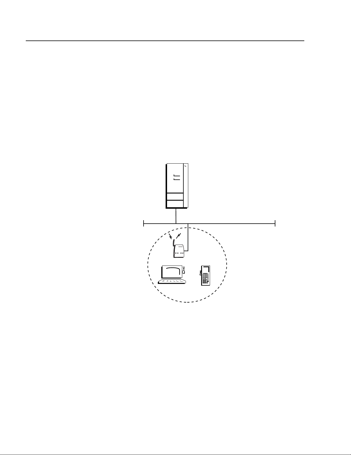
In a simple wireless network, a single access point on the wired network
serves as a transparent bridge between the wired network and end
devices. The end devices communicate exclusively with devices on the
wired network; they do not communicate with other end devices. This
kind of simple wireless network is illustrated in Figure 4.
Host
Ethernet
UAP
Figure 4 Simple Wireless Network
22
Page 23
AT-WL2411 Version 1.80 Installation and User’s Guide
Using Multiple
APs and
Roaming End
Devices
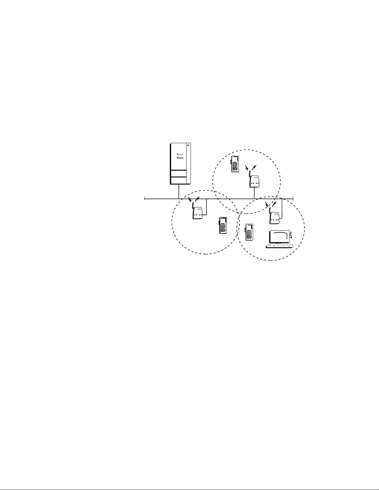
For larger or more complex environments, you can install multiple
access points so end devices can roam from one access point to another.
Multiple access points establish coverage areas or cells similar to those
of a cellular telephone network. End devices can connect with any
access point that is within range and belongs to the same network.
With the access point multichannel architecture, you can have more
than one access point within the same cell area to increase throughput.
In addition, overlapping radio coverage cells offer redundancy for critical
applications so that coverage is not lost if a single access point or radio
fails. This kind of network is illustrated in Figure 5.
Host
UAP
Ethernet
UAP
UAP
UAP
Figure 5 Multiple APs and Roaming End Devices
23
Page 24
Product Description
Using APs to
Create a Point-
to Point Bridge
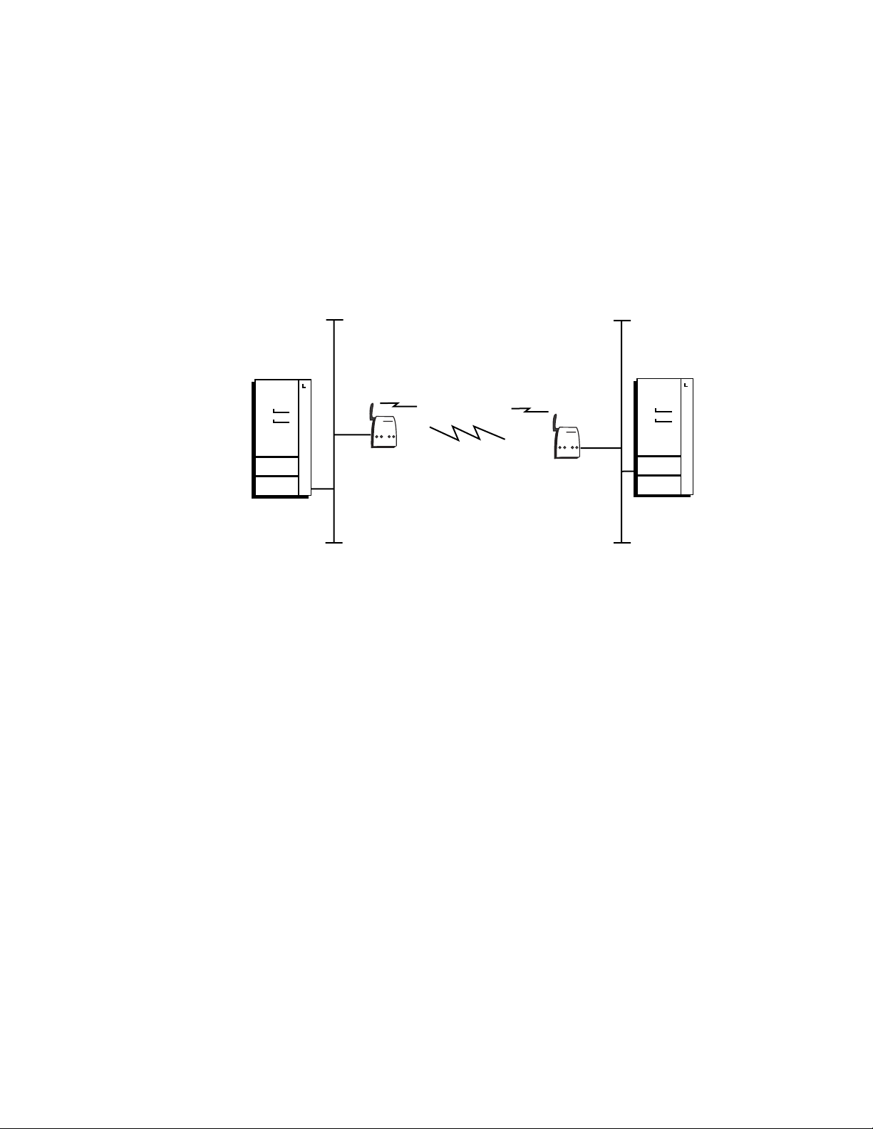
You can use access points to create a wireless or point-to-point bridge
between two LANs. You can have a access point wired to a network in
one building and have a second access point wired to a network in
another building. Wired clients in both buildings can then communicate
with each other over the wireless bridge created by the access points.
This configuration is useful in a campus environment where pavement
or other objects prevent installation of a wired link. For information
about configuring access points for point-to-point bridging, see
Configuring Wireless Hops. Figure 6 illustrates a network with a point-topoint bridge.
Ethernet Ethernet
Host
UAP
UAP
Host
Figure 6 APs as a Bridge Between Wired LANs
24
Page 25

Chapter 2
Installation
This chapter contains the following sections:
❑ Installation Safety Precautions on page 26
❑ Selecting a Site for the Access Point on page 27
❑ Verifying Package Contents on page 29
❑ Installing the Access Point on page 30
❑ Attaching an External Antenna (Optional) on page 33
❑ Warranty Registration on page 35
25
Page 26

Installation
Installation Safety Precautions
Please review the following safety precautions before you begin to
install the access point. Refer to Translated Electrical Safety and Emission
Information on page 221 for statements in your language.
Warning
Power to the access point must be sourced only from the
adapter:
Europe—EC
Use TÜV licensed AC adapter of 5 V DC, min 2.0 A.
Other Countries
Use a Safety Agency Approved AC adapter of 5 V DC, min 2.0 A. 4
Warning
Power cord is used as a disconnection device: To de-energize
equipment, disconnect the power cord. 5
Warning
Lightning Danger: Do not work on this equipment or cables
during periods of lightning activity. 6
Caution
Air vents: The air vents must not be blocked on the unit and must
have free access to the room’s ambient air for cooling. 7
Caution
Operating Temperature: This product is designed for a maximum
ambient temperature of 65°C. 8
Caution
All Countries: Install this product in accordance with local and
national electric codes. 9
26
Page 27

Selecting a Site for the Access Point
Allied Telesyn recommends that you have Allied Telesyn or other
certified providers conduct a site survey to determine the ideal locations
for all of your network components. A proper site survey requires special
equipment and training.
Observe the following requirements when choosing a site for your
access point:
❑ If you are installing the access point on a table, be sure that the
table is level and secure.
❑ The power outlet for the access point should be located near the
unit and should be easily accessible.
❑ The site should provide for easy access to the ports on the access
point. This will make it easy for you to connect and disconnect
cables.
AT-WL2411 Version 1.80 Installation and User’s Guide
❑ Try to position the access point so that its LEDs are visible. The
LEDs are useful for troubleshooting.
❑ To allow proper cooling of the access point, air flow around the
unit and through its vents on the side and rear should not be
restricted.
❑ Do not place objects on top of the access point.
❑ Do not expose the access point to moisture or water.
❑ Make sure that the site is a dust-free environment.
❑ You should use dedicated power circuits or power conditioners to
supply reliable electrical power to the access point.
❑ Locate access points centrally within areas requiring coverage.
❑ Overlap access point coverage areas to avoid coverage holes.
❑ Access points configured for the frequency in the same coverage
area may interfere with each other and decrease throughput. You
can reduce the chance of interference by configuring your access
points so they are configured 5 channels apart, such as Channels
1, 6, and 11.
❑ Install wired LAN cabling within de vice limit and cable length
limitations.
27
Page 28

Installation
❑ Microwave ovens operate in the same frequency band as the
802.11b HR radio; therefore, if you use a microwave within range
of your Allied Telesyn RF network, you may notice network
performance degradation. Both your microwave and your RF
network will continue to function, but you may want to consider
relocating your microwave out of range of your access point.
The access point features an advanced configuration
parameter for the 802.11b HR radio called microwave oven
robustness. You can enable this parameter to minimize
potential interference between your microwave oven and
your RF network.
28
Page 29

Verifying Package Contents
Make sure the following items are included in your package. If any item
is missing or damaged, contact your Allied Telesyn sales representative
for assistance.
❑ One AT-WL2411 Access Point
❑ Mounting bracket
❑ Power supply and AC power cord
❑ Documentation CD
AT-WL2411 Version 1.80 Installation and User’s Guide
Cables Not
Included
The AT-WL2411 Access Point requires the cables described in Table 2.
These cables are not included with the access points.
Table 2 Cables
Port Cable Connector
Ethernet Category 3 or better 100-ohm unshielded
RJ-45
straight-through or crossover twisted
pair cable
Serial RS-232 null-modem RS-232
29
Page 30
Installation
H
(
s
Installing the Access Point
You can install the AT-WL2411 horizontally on a desk or counter, or you
can install it vertically to a wall using the wall bracket that ships with it.
An optional cubicle bracket is also available for mounting the
AT-WL2411 on a cubicle wall.
Wall-mounting the AT-WL2411
To install the mounting bracket and AT-WL2411 on a sturdy surface in
accordance with local building codes, you need the following tools and
materials:
❑ Two #5 or M3 screws.
❑ Drill and drill bit appropriate for the mounting screws
❑ Screwdriver
To wall-mount the AT-WL2411, perform the following procedure:
1. Using the mounting bracket as a template, mark the location of the
mounting holes on the wall.
2. Drill the mounting holes.
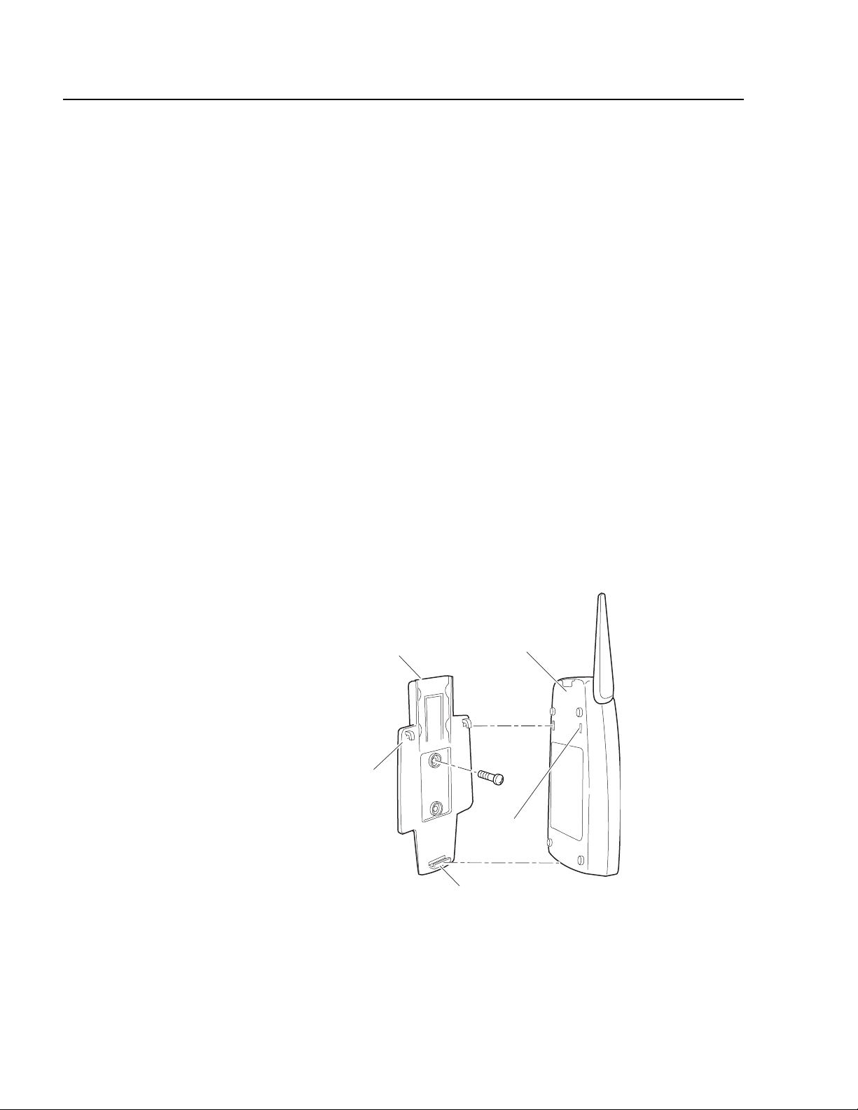
3. Position the wall-mounting bracket on the wall and using the M3
screws (not provided), secure the bracket to the wall, as shown in
Figure 7.
Mounting
bracket
AT-WL2411
2102 back
panel
Screw
ook
2 places)
(2 places)
Slot
(2 places)
Clip
2102G009.ep
Figure 7 Wall-mounting the Access Point
30
Page 31

AT-WL2411 Version 1.80 Installation and User’s Guide
90°
180°
0°
4. Fit the slots on the back of the AT-WL2411 over the hooks on the
mounting bracket.
5. Slide the AT-WL2411 up slightly and then press the base of the
AT-WL2411 until it clicks into the clip at the bottom of the wallmounting bracket.
6. Using the guidelines below, position the antenna accordingly. See to
Figure 8.
❑ Place the antenna at 90° when using the AT-WL2411 horizontally;
for instance, on a desk or counter.
❑ Place the antenna at 180° when using the AT-WL2411 vertically;
for instance, mounted on a wall or cubicle.
Note
Keep the antenna at 0° when in storage.
Figure 8 Positioning the Antenna
Note
Do not force the antenna past the 0° or 180° or you may break the
antenna connector.
7. Attach the data cable to the unit by, first connecting the Ethernet
cable to the Ethernet port on the access point and then attach the
other end of the cable to your Ethernet network.
31
Page 32

Installation
8. To configure the access point or assign it an IP address for remote
configuration, attach one end of the RS-232 null-modem
management cable to the serial port on the unit and then attach the
other end of the cable to the serial port on your computer. For
instructions on how to further configure the access point, see
Configuration Overview on page 37.
9. Power ON the unit by plugging one end of the power cord into the
power port on the access point and plug the other end into an AC
power outlet. The AT-WL2411 does not have an ON/OFF switch, so it
turned ON as soon as you apply power.
Caution
You must use the appropriate Allied Telesyn power supply with this
device or equipment damage may occur.
Your AT-WL2411 is now ready to begin transmitting data packets
between your end devices and your wired network.
32
Page 33

AT-WL2411 Version 1.80 Installation and User’s Guide
P
t
or
Attaching an External Antenna (Optional)
To attach an external antenna, you must disconnect the built-in antenna
and attach an antenna cable directly to the radio card in the access
point. For more information about antenna options, contact your local
Allied Telesyn representative.
To attach an antenna cable to the AT-WL2411, perform the following
procedure:
1. Remove the Radio Card Door. Refer to Figure 9.
2. Using pliers, gently pull the antenna wire to disconnect it from the
radio card, as shown in Figure 9.
Door
Antenna
wire
Figure 9 Antenna Wire
3. Tuck the antenna wire inside the access point housing.
4. Remove the punch-out tab from the door, as shown in Figure 10.
Do
unch-out
ab
Figure 10 Punch-out Tab
Pliers
33
Page 34

Installation
5. Attach the antenna cable to the radio by inserting the cable
connector into the radio card.
6. Replace the door.
The AT-WL2411 is now ready for use.
34
Page 35

Warranty Registration
When you have finished installing the access point, register your product
by completing the enclosed warranty card and mailing it to Allied
Telesyn.
AT-WL2411 Version 1.80 Installation and User’s Guide
35
Page 36

Page 37

Chapter 3
Configuration Overview
The AT-WL2411 Access Point features three different management
interfaces:
❑ Using a Serial Connection on page 38
❑ Using a Web Browser on page 43
❑ Using a Telnet Session on page 47
Note
You must first access the management firmware using a
communications program via serial connection to assign the
AT-WL2411 an IP address before you can use the other
management interface options. To assign an IP Address, refer to
Assigning an IP Address on page 41.
37
Page 38

Configuration Overview
Using a Serial Connection
Although the AT-WL2411 Access Point will work directly out of the box,
you must assign it an IP Address and define other basic parameters
before you can manage it remotely. To perform these initial
configurations, you must use a serial connection and a terminal or a
communications program (such as HyperTerminal). This manual
assumes that you are using a communications program for your initial
configuration and performing all other configurations remotely using
the Web interface.
To perform a basic configuration of the AT-WL2411 using the default
settings, you need the following:
❑ An RS-232 null-modem cable
❑ A terminal or PC with an open serial port
To configure the AT-WL2411, perform the following procedure:
1. Use the RS-232 null-modem cable to connect the serial port on the
access point to a serial port on your PC.
2. Open your communications program and configure the serial
communications parameters on your PC to:
Baud 9600
Data bits 8
Parity no
Stop bit 1
Flow control none
3. Connect the power cable to the access point and to a power source.
The access point does not have an ON/OFF switch, so the unit is ON as
soon as power is applied.
38
Page 39

AT-WL2411 Version 1.80 Installation and User’s Guide
4. Press Enter when the message Starting system appears on your PC
screen. The Login screen shown in Figure 11 is displayed..
Figure 11 Login Screen
5. Type atilan as the user name (default) and press <Enter>.
6. Then type atilan as the password (default) and press <Enter>. The
Configuration Menu as shown in Figure 12 is displayed.
Figure 12 Configuration Menu
39
Page 40

Configuration Overview
7. To assign the access point an IP address so that you can continue
configuration remotely, proceed to the next section Assigning an IP
Address on page 41.
8. To continue configuration using the serial connection, use the menu
shown in Figure 12.
9. When you have finished your configurations, save you changes by
using the Save Configuration option and then reboot the access
point to activate your changes.
40
Page 41

Assigning an IP Address
The AT-WL2411 will work directly out of the box if you are using a DHCP
server to assign it an IP Address. By default, the access point is
configured to be a DHCP client. However, if you are not using a DHCP
server to assign IP Address, you must assign the access point an IP
Address before you can manage it remotely.
1. To use DHCP to automatically assign an IP Address, configure the
following parameters in the TCP/IP Settings Menu. These parameters
are describe below.
DHCP Mode
Set to <Use DHCP if IP Address is zero>.
DHCP Server Name
The name of the DHCP server that the AT-WL2411 is to access for
automatic address assignment. If no server name is specified, the
AT-WL2411 responds to offers from any server.
AT-WL2411 Version 1.80 Installation and User’s Guide
To assign an IP Address manually, configure these parameters in
the TCP/IP Settings Menu:
IP Address
A unique IP Address.
IP Subnet Mask
The subnet mask that matches the other devices in your network.
IP Router (Gateway)
The address of the router that will forward frames if the
AT-WL2411 will communicate with devices on a subnetwork.
2. If you are configuring a AT-WL2411, you must configure Node Type in
the Wireless Bridging submenu of the 802.11b Radio Menu. Configure
Node Type as Master if this access point will communicate with end
devices; configure it as Station if you are configuring a access point to
communicate with an Master access point on the wired network.
3. In the Spanning Tree Settings Menu, configure LAN ID (Domain). All
access points must have the same LAN ID to participate in the same
spanning tree.
41
Page 42

Configuration Overview
4. In the 802.11b Radio Menu, configure the parameters. These
parameters are described below.
(SSID) Network Name
The network name. All 802.11b radios must have the same
network name to communicate.
Frequency
The frequency appropriate for your installation. Frequencies
range from 2.4 to 2.5 GHz and depend on the specific country.
5. Save the configurations by using the Save Configuration option and
reboot the access point to activate your changes.
Now that the access point has an IP Address, you can configure it
remotely using the procedures in the next sections.
42
Page 43

Using a Web Browser
After you have configured the IP address and other basic network
parameters as described in Assigning an IP Address on page 41, you can
manage your access point using a Web browser.
Y ou must know the IP Address of the acc ess point to manage it remot ely.
If a DHCP server assigned the IP Address, you must determine the IP
Address from the DHCP server.
Only one session can be active on the access point at a time. If your
session terminates abruptly or a new sign-on screen appears, someone
else may be using the access point.
When using the Web to establish remote management of your access
point, follow these guidelines:
❑ Your session will terminate if it is not used for 15 minutes
❑ Console Command mode is not available
AT-WL2411 Version 1.80 Installation and User’s Guide
To establish a Web browser session with the AT-WL2411, perform the
following procedure:
1. Type the DHCP server-assigned IP Address or the IP Address you
assigned to the AT-WL2411 in the address field of your Web browser.
Note
If you access the Internet using a proxy server, you must add the IP
Address to your exceptions list. The exceptions list contains the
addresses that you do not want to use with a proxy server.
2. Press <Enter>. The Access Point Login screen as shown in Figure 13 is
displayed.
43
Page 44

Configuration Overview
Figure 13 Access Point Login Screen
3. Type atilan as both the user name and password (defaults).
Note
You can change the user name and password from the Security
Menu.
44
Page 45

AT-WL2411 Version 1.80 Installation and User’s Guide
4. Select Login. The TCP/IP Settings screen as shown in Figure 14 is
displayed.
Figure 14 TCP/IP Settings Screen
You can now configure the AT-WL2411 using the Web browser menus.
45
Page 46

Configuration Overview
Saving Your Configuration Changes
There are two ways to sa ve y our c onfiguration settings in a Web browser
session:
❑ Submit Changes
When you select Submit Changes, the access point updates the
current configuration file. The access point does not change the
active configuration file. You can see a list of pending changes
when you click Save/Discard Changes. Having separate files for
the current and active configurations lets you make changes
while the access point is running without interrupting
communication.
❑ Save Discard/Changes
When you select Save/Discard Changes and then you select Save
Changes and Reboot, the access point copies the current
configuration file to the active configuration file. The active
configuration file is the file that the access point uses.
Note
You must save your configuration changes and reboot the access
point in order for the new configurations to become active.
46
Page 47

Using a Telnet Session
To establish a Telnet configuration session, perform the following
procedure:
1. Go to an MS-DOS prompt and type Telnet IP address, where
IPaddress has the form x.x.x.x and x is a numb er from 0 to 255. Use the
IP address assigned to the AT-WL2411 you want to configure.
or
Open a Telnet program and type open. Press <Enter>. At the
<open> prompt, type the IP address of the AT-WL2411 and press
<Enter>.
2. Follow the configuration instructions in Using a Serial Connection on
page 38, since the Telnet interface is similar to this communication
program interface.
AT-WL2411 Version 1.80 Installation and User’s Guide
47
Page 48
Configuration Overview
Using SNMP
The access point supports SNMP management. Contact your Allied
Telesyn representative for information about obtaining a copy of the
MIB. The passwords for accessin g the SNMP community table are sho wn
below.
Ty pe of Access MIB Password
read only public
read/write CR52401
Configuring the
SNMP
Community
Simple Network Management Protocol (SNMP) community strings are
passwords used by SNMP. When you use an SNMP client, you must enter
the correct community string to gain access to the access point SNMP
interface.
To configure the SNMP community, perform the following procedure:
1. Establish a Web browser session if you have not already done so. For
more information, see Using a Web Browser on page 43.
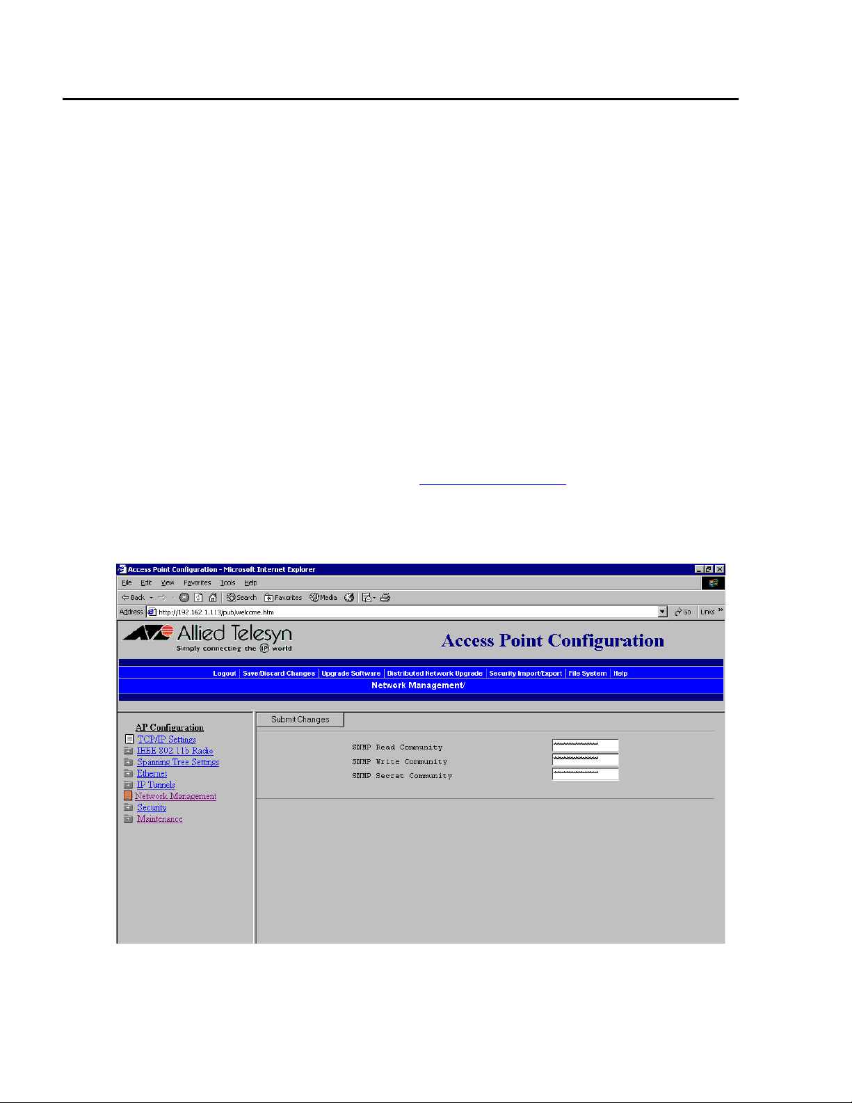
2. From the Main Menu, select Network Management. The Community
Strings screen as shown in Figure 15 is displayed.
48
Figure 15 Community Strings Screen
Page 49

AT-WL2411 Version 1.80 Installation and User’s Guide
3. Configure the SNMP community parameters. The SNMP community
parameters are explained below.
SNMP Read Community
Allows read-only access. Defaults to public.
SNMP Write Community
Allows read/write access. Defaults to CR52401.
SNMP Secret Community
Allows read/write access to change the community strings.
Defaults to Secret.
4. When you are finished, select Submit Changes to save your changes.
49
Page 50

Page 51

Chapter 4
Configuring the Ethernet Network
This chapter contains the following sections:
❑ Configuring the TCP/IP Settings on page 52
❑ Configuring the Ethernet Settings on page 63
❑ Configuring Ethernet Filters on page 64
51
Page 52

Configuring the Ethernet Network
Configuring the TCP/IP Settings
If you are using a DHCP server to automatically assign an IP address to
the access point, go to Configuring the Access Point as a DHCP Client in
the next section. If you are not using a DHCP server, you need to
manually assign some TCP/IP parameters.
You should have already configured an IP address for the access point,
as described in Assigning an IP Address on page 41.
To configure the TCP/IP settings, perform the following procedure:
1. From the Main Menu, select TCP/IP Settings. The TCP/IP Settings
screen as shown in Figure 16 is displayed..
52
Figure 16 TCP/IP Settings Screen
2. Configure the TCP/IP settings using the following parameters:
IP Address
Enter the IP Address of the AT-WL2411. The IP Address has the
form x.x.x.x where x is a number from 0 to 225.
Page 53

AT-WL2411 Version 1.80 Installation and User’s Guide
IP Subnet Mask
Enter the subnet mask that matches the other devices in your
network. The subnet mask has the form x.x.x.x, where x is a
number from 0 to 225.
IP Router
Enter the IP Address of the router that will forward packets if the
access point will communicate with devices on another subnet.
The IP Address has the form x.x.x.x, where x is a number from 0 to
225.
IP Frame Type
This parameter controls the encapsulation of IP frames sent by
this access point. You select either DIX (Ethernet 2.0) or SNAP
encapsulation.
DIX
Encapsulate using DIX (Ethernet 2.0) frames.
SNAP
Encapsulate using SNAP frames. You need to use SNAP if other
network computers use SNAP encapsulation for IP frames.
3. Do one of the following:
❑ If you want to configure the access point as a NAT server, refer to
About Network Address Translation (NAT) on page 59.
❑ If you want to configure the access point to send ARP requests,
see Configuring the Access Point to Send ARP Requests on page
61.
❑ If you want to configure the access point as a DHCP server, see
Configuring the Access Point as a DHCP Server
on page 55.
4. Select Submit Changes to save your changes. To activate your
changes, select Save/Discard Changes from the menu bar and then
select Save Changes and Reboot. For help, see Saving Your
Configuration Changes on page 46.
53
Page 54

Configuring the Ethernet Network
Configuring the
Access Point as
a DHCP Client
You can use a DHCP server to automatically assign an IP Address to your
access point; that is, the access point can act as a DHCP client.
Note
You cannot configure the access point as both a DHCP server and a
DHCP client.
To configure the access point as a DHCP client, perform the following
procedure:
1. From the Main Menu, select TCP/IP Settings. The TCP/IP Settings
screen as shown in Figure 17 is displayed.
54
Figure 17 TCP/IP Settings Screen
2. Select the down arrow on the right side of the DHCP Mode field and
choose either Always Use DHCP or Enabled, if IP Address is Zero. If
you choose Enabled, if IP Address is Zero, make sure that the IP
Address field is 0.0.0.0.
Page 55

AT-WL2411 Version 1.80 Installation and User’s Guide
3. In the DHCP Server Name field, enter the name of the DHCP server
that the access point is to access for automatic address assignment. If
no server name is specified, the access point responds to offers from
any server.
4. Select Submit Changes to save your changes. To activate your
changes, select Save/Discard Changes from the menu bar and then
select Save Changes and Reboot. For help, see Saving Your
Configuration Changes on page 46.
Configuring the
Access Point as
a DHCP Server
You can configure the AT-WL2411 as a simple DHCP server that can
provide DHCP server functions for small installations where no other
DHCP server is available. The DHCP server will offer IP Addresses to any
DHCP client it hears as long as a pool of unallocated IP Addresses is
available. These clients may include other access points, wireless end
devices, wired hosts on the distribution LAN, or wired hosts on
secondary LANs.
Note
If you configure the access point as a DHCP server, it is not intended
to replace a general purpose, configurable DHCP server, and it
makes no provisions for synchronizing DHCP policy between itself
and other DHCP servers. Customers with complex DHCP policy
requirements should use other DHCP server software.
Note
You cannot configure the access point as both a DHCP server and a
DHCP client.
To avoid a single point of failure, you can configure more than one
access point to be a DHCP server; however, the access points do not
share DHCP client databases. You should configure each DHCP server
with a different DHCP address pool from which to allocate client
addresses.
55
Page 56

Configuring the Ethernet Network
To configure the access point as a DHCP server, perform the following
procedure:
1. From the Main Menu, select TCP/IP Settings. The TCP/IP Settings
screen as shown in Figure 18 is displayed.
56
Figure 18 TCP/IP Settings Screen
2. Verify that the IP Subnet Mask field and IP Router field are configured.
For help, see Configuring the TCP/IP Settings
on page 52.
3. Select the down arrow on the right side of the DHCP Mode field and
choose This AP is a DHCP Server.
4. Select Submit Changes to save your changes.
Page 57

AT-WL2411 Version 1.80 Installation and User’s Guide
5. Select DHCP Server Setup. The DHCP Server Setup screen as shown
in Figure 19 is displayed.
Figure 19 DHCP Server Setup
6. Configure the DHCP server using the following parameters:
Low Address
The low IP Address in the range of IP Addresses available to the
DHCP server for distribution to DHCP clients. If these addresses
are not on the same subnet as the access point, the access point
will perform Network Address Translation (NAT) for the devices to
which it grants IP Addresses.
High Address
the high IP address in the range of IP Addresses available to the
DHCP server for distribution to DHCP clients. If these addresses
are not on the same subnet as the access point, the access point
will perform Network NAT for the devices to which it grants IP
Addresses.
DNS Address 1
The IP Address of a Domain Name Server that will be distributed
to DHCP clients. You can enter up to two DNS addresses to be
delivered to DHCP clients.
57
Page 58

Configuring the Ethernet Network
DNS Address 2
The IP address of a Domain Name Server that will be distributed to
DHCP clients. You can enter up to two DNS addresses to be
delivered to DHCP clients.
Lease Time
Specifies the duration of the leases that are granted by the DHCP
server. Enter the lease time in the format days:hours:minutes. If
you set the lease time to 0, infinite leases are granted
7. Select Submit Changes to save your changes and then select here.
To activate your changes, select Save/Discard Changes from the
menu bar and then select Save Changes and Reboot. For help, see
Saving Your Configuration Changes on page 46.
Supported DHCP Server Options
The DHCP server issues IP address leases to configure this field:
IP broadcast address
The IP broadcast address, along with the subnet mask and IP router, will
contain the same values as those configured for the access point.
Unsupported DHCP Server Options
The DHCP server does not support any DHCP options other than those
listed. The DHCP server disregards any DHCP options that are not
explicitly required by the DHCP specification. The DHCP server ignores
all packets with a non-zero giaddr (gateway IP address). The DHCP server
only responds to requests from its own subnet.
58
Page 59

AT-WL2411 Version 1.80 Installation and User’s Guide
About Network
Address
Translation
(NAT)
NAT allows IP addresses to be used by more than one device. The access
point can act as a NAT server, which instantaneously rewrites IP
addresses and port numbers in IP headers so that packets all appear to
be coming from (or going to) the single IP address of the access point
instead of the actual source or destination.
When a device uses the access point as an IP router, the access point
replaces the IP header, which includes the device’s MAC address, IP
source address, and TCP/UDP port, with its own. You can configure the
DHCP server to indicate that the access point is the IP router when the
server allocates an IP address. Special consideration is given to changing
the FTP data connection TCP port number, which is in the body of the
TCP packet. After the packet source is modified, it is forwarded to the
proper subnet.
If the destination subnet is not the same subnet as the access point’s
Ethernet network, the destination MAC address is changed to the IP
router that has been configured for the access point. If destination
subnet is the same subnet as the access point’s Ethernet network, the
access point converts the MAC address to the MAC address that belongs
to the destination IP address. This may involve using ARP for MAC
address discovery.
When the access point receives a packet with its IP address, it identifies
the need for address translation by inspecting the destination port
number. If the port number is within the pool reserved for NAT
operation, it looks up the original MAC address, IP address, and port
number. The packet is then modified and forwarded to the end device.
NAT operation is disabled or enabled automatically depending on the
continuous range of addresses you enter into the DHCP server. NAT is
disabled if the range of addresses to be given to DHCP clients is on the
same subnet as the access point. NAT is enabled if the range of
addresses to be given to DHCP clients is not on the same subnet as the
access point; thus, you are creating a virtual network and the DHCP
server will also perform NAT translation.
When NAT operation is enabled, the access point uses the low address in
the range of addresses as its own. The DHCP/NAT clients also use this
address as their router IP address. These clients can configure the access
point using this internal IP address or the normal external IP address.
59
Page 60

Configuring the Ethernet Network
To configure the access point as a NAT server, perform the following
procedure:
1. From the Main Menu, select TCP/IP Settings. The TCP/IP Settings
screen as shown in Figure 16 is displayed.
60
Figure 20 TCP/IP Settings Screen
2. Verify that the IP Address field and IP Subnet Mask field are
configured. For help, see Configuring the TCP/IP Settings
on page 52.
3. Select the down arrow on the right side of the DHCP Mode field and
choose This AP is a DHCP Server.
4. Select Submit Changes to save your changes.
5. Select DHCP Server Setup and enter a range of IP addresses that are
NOT on the same subnet as the access point.
6. Select Submit Changes to save your changes. To activate your
changes, Select Save/Discard Changes from the menu bar and then
Select Save Changes and Reboot. For help, see Saving Your
Configuration Changes on page 46.
Page 61
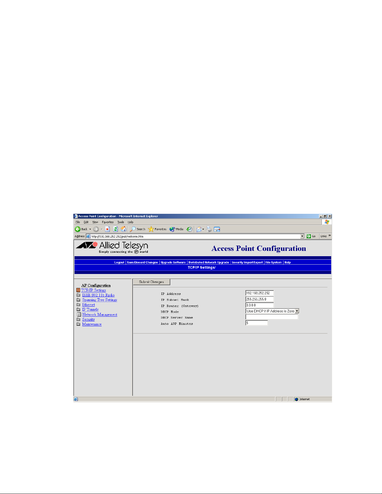
AT-WL2411 Version 1.80 Installation and User’s Guide
Configuring the
Access Point to
Send ARP
Requests
ARP requests are multicast packets, which means they are sent to all
devices on the network. The access point periodically sends an
unsolicited ARP request to the default IP router so that all routers can
update their routing tables. This ARP request enables a network
management program to learn about the access point on the network
by querying routers. The auto ARP period controls the time interval
between ARP broadcasts.
If the address of the default IP router is 0.0.0.0, the access point sends an
ARP request to its own IP address. Without this option, an access point
might not use its IP address for extended periods of time and the IP
address would expire from the router ARP table. If the IP address expires,
the network management program must ping all potential addresses on
a subnet to locate active IP addresses or require the user to enter a list.
You should not let the IP address for the access point expire.
To set the auto ARP period, perform the following procedure:
1. From the Main Menu, select TCP/IP Settings. The TCP/IP Settings
screen as shown in Figure 21 is displayed.
Figure 21 TCP/IP Settings Screen
61
Page 62

Configuring the Ethernet Network
2. In the Auto ARP Minutes field enter a time period from 1 to 120
minutes. To disable this parameter, set the time period to 0.
3. Select Submit Changes to save your changes. To activate your
changes, Select Save/Discard Changes from the menu bar and then
select Save Changes and Reboot. For help, see Saving Your
Configuration Changes on page 46.
62
Page 63

Configuring the Ethernet Settings
Many of the standard Ethernet settings are configured in the TCP/IP
Settings screen. For help, see Configuring the TCP/IP Settings on page
52. In the Ethernet Settings screen, you can
❑ Enable or disable the link status check. Enable this parameter if
you want the access point to periodically check its Ethernet
connection. If it loses the connection, this access point can no
longer be the root access point and any end devices that are
connected to this access point (whether or not it is the root) will
roam to a different access point. The access point will attempt to
reconnect to the spanning tree through one of its radio ports.
Disable this parameter if this access point must be the root access
point.
❑ Set the hello period, which defines how often the access point
sends out multicast hello packets so it can dynamically discover
and test connections to other routers on the network. Once this
information is learned, the access point and routers can exchange
routing information.
AT-WL2411 Version 1.80 Installation and User’s Guide
63
Page 64

Configuring the Ethernet Network
Configuring Ethernet Filters
You can set both Ethernet and IP tunnel filters, and you can create
protocol filters for both predefined and user-defined protocol types. In
addition, you can define arbitrary frame filters based on frame content.
For help with configuring IP filters, see Configuring IP Tunnel Filters on
page 102.
Configuring the
Ethernet
Address Table
You can use the Ethernet address table to list the permanent unicast 802
MAC addresses that are using the access point that is the designated
bridge on the secondary LAN to communicate to the primary LAN. These
addresses become permanent entries in the route table of the
designated bridge on the secondary LAN.
You must enter the MAC addresses of the devices on the secondary LAN
that do not always initiate communication.
You should fill in this table when configuring designated bridges for
secondary LANs so that this access point will not need to flood frames to
all the wired stations on the secondary LAN. If you choose not to use this
table, the access point may need to flood frames to all ports (Ethernet
and radio) to learn the path to the MAC address.
To configure the Ethernet address table, perform the following
procedure:
1. From the Main Menu, select Ethernet.
2. Select Address Table. The Address Table screen as shown in Figure
22 is displayed.
64
Page 65

AT-WL2411 Version 1.80 Installation and User’s Guide
Figure 22 Address Table Screen
3. You can enter up to 20 MAC addresses. MAC addresses consist of six
hex pairs that are separated by spaces, colons, or hyphens.
4. Select Submit Changes to save your changes. To activate your
changes, select Save/Discard Changes from the menu bar and then
select Save Changes and Reboot. For help, see Saving Your
Configuration Changes on page 46.
65
Page 66

Configuring the Ethernet Network
Using Ethernet
Frame Type
Filters
You can define filters for common networking protocols such as IP,
Novell IPX, and 802.2 LLC. You can also set filters that will pass only those
Ethernet frame types found on your network.
You can set the default action for general and specific frame types. For
example, you can set the DIX-Other EtherTypes frame parameter to
drop, and then use the subtype menus to pass only those specific DIX
types that are used in your radio network.
You can also set the scope for general and specific frame types. For
example, you can set the action to Drop and the scope to All for DIX-IPTCP Ports, and then all IP packets with the TCP type will be dropped even
if specific TCP parts are set to pass in the subtype menus.
Action
Set the action to Pass or Drop. If you select Pass, then all frames of
that type are passed. If you select Drop, then all frames of that
type are dropped.
Scope
Set scope to Unlisted or All. If you select All, then all frames of that
type are unconditionally passed or dropped, depending on the
action you specified. If you select Unlisted, then frames are passed
or dropped only if the frame type is not listed in the predefined or
customizable tables.
To set frame type filters, perform the following procedure:
66
Page 67

AT-WL2411 Version 1.80 Installation and User’s Guide
1. From the Main Menu, select Ethernet then Frame Type Filters. The
Frame Type Filters screen as shown in Figure 23 is displayed.
Figure 23 Frame Type Filters Screen
2. In each frame type field, select the down arrow on the right side of the
Action field and set the action to Pass or Drop.
3. In each frame type field, select the down arrow on the right side of the
Scope field and set the scope to Unlisted or All.
67
Page 68

Configuring the Ethernet Network
Note
If you set the Scope field to Unlisted for any of the frame types, you
must also configure predefined subtype filters or customizable
subtype filters. For help, see Using Predefined Subtype Filters on
page 69 or Customizing Subtype Filters on page 70.
The various frame types are explained below:
DIX IP TCP Ports
DIX IP UDP Ports
SNAP IP TCP Ports
SNAP IP UDP Ports
Primary Internet Protocol Suite (IP) transport protocols.
DIX IP Other Protocols
SNAP IP Other Protocols
IP protocols other than TCP or User Datagram Protocol (UDP).
DIX IPX Sockets
Novell NetWare protocol over Ethernet II frames.
SNAP IPX Sockets
Novell NetWare protocol over 802.2 SNAP frames.
802.3 IPX Sockets
Novell NetWare protocol over 802.3 RAW frames.
DIX Other Ethernet Types
SNAP Other Ethernet Types
DIX or SNAP registered protocols other than IP or IPX.
802.2 IPX Sockets
Novell running over 802.2 Logical Link Control (LLC).
802.2 Other SAPs
802.2 SAPs other than IPX or SNAP.
Note
You cannot filter HTTP, Telnet, SNMP, and ICMP frames because they
are used for configuration and management of the access point.
Additionally, you cannot filter broadcast ARP request packets if the
target IP address belongs to the local access point or to an access
point in the subtree rooted at the local access point.
68
Page 69

AT-WL2411 Version 1.80 Installation and User’s Guide
4. Select Submit Changes to save your changes. To activate your
changes, select Save/Discard Changes from the menu bar and then
Save Changes and Reboot. For help, see Saving Your Configuration
Changes on page 46.
Using
Predefined
Subtype Filters
You can configure the access point to pass or drop certain predefined
frame subtypes.
To configure predefined subtype filters, perform the following
procedure:
1. From the Main Menu, select Ethernet and then Predefined Subtype
Filters. The Predefined Subtype Filters screen as shown in Figure 24
is displayed.
Figure 24 Predefined Subtype Filters Screen
2. In each Allow/Pass field, check or uncheck the boxes to choose Allow
or Pass.
69
Page 70

Configuring the Ethernet Network
3. Select Submit Changes to save your changes. To activate your
changes, select Save/Discard Changes from the menu bar and then
Save Changes and Reboot. For help, see Saving Your Configuration
Changes on page 46.
Customizing
Subtype Filters
You can configure the AT-WL2411 to pass or drop certain customized
frame subtypes. You define the action, subtype, and value parameters.
Action
Set the action to Pass or Drop. If you select Pass, then all frames of that
subtype and value are passed. If you select Drop, then all frames of that
subtype and value are dropped.
Subtype
Selects the frame subtype you wish to configure.
Value
The following table describes frame subtypes and their values. The value
must be two hex pairs. You must enter port values as decimals; for
example, enter 23. for port 23. The access point displays the
hexadecimal equivalent in the Value field on the menu. When a match is
found between frame subtype and value, the specified action is taken.
To customize subtype filters, perform the following procedure:
70
Page 71

AT-WL2411 Version 1.80 Installation and User’s Guide
1. From the Main Menu, select Ethernet and then Customizable
Subtype Filters. The Customizable Subtype Filters screen as shown
in Figure 25 is displayed.
Figure 25 Customizable Subtype Filters Screen
2. Check or uncheck the boxes under the Allow/Pass field to choose
Allow or Pass.
3. Selet the down arrow on the right side of the SubType field and
choose the customizable frame subtype. The frame subtype filters
and their values are defined below.
DIX-IP-TCP-Port
Port value in hexadecimal.
71
Page 72

Configuring the Ethernet Network
DIX-IP-UDP-Port
Port value in hexadecimal.
DIX-IP-Protocol
Protocol number in hexadecimal.
DIX-IPX-Socket
Socket value in hexadecimal.
DIX-EtherType
Specify the registered DIX type in hexadecimal.
SNAP-IP-TCP-Port
Port value in hexadecimal.
SNAP-IP-UDP-Port
Port value in hexadecimal.
SNAP-IP-Protocol
Port value in hexadecimal.
SNAP-IPX-Socket
Socket value in hexadecimal.
SNAP-EtherType
SNAP type in hexadecimal. To filter on both SNAP type and OUI,
use advanced filters.
802.3-IPX-Socket
Socket value in hexadecimal.
802.2-IPX-Socket
Socket value in hexadecimal.
802.2-SAP
802.2 SAP in hexadecimal.
4. In the Value field enter the two hex pairs.
5. Select Submit Changes to save your changes. To activate your
changes, select Save/Discard Changes from the menu bar then Save
Changes and Reboot. For help, see Saving Your Configuration
Changes on page 46.
72
Page 73
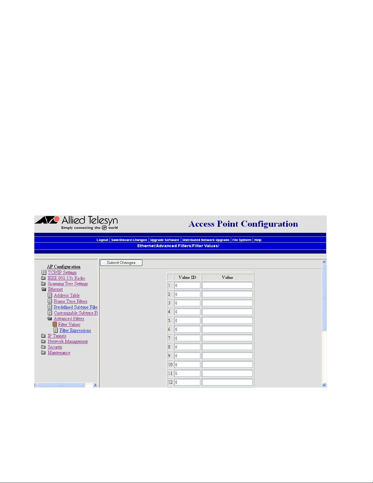
AT-WL2411 Version 1.80 Installation and User’s Guide
Configuring
Advanced
Filters
Setting Filter
Values
You can configure advanced filters if you need more flexibility in your
filtering. Settings for advanced filters execute after those for other filters;
that is, advanced filters are only applied if the frame has passed the
other filters.
You can use filter values and filter expressions to minimize network
traffic over the wireless links; however, it is recommended that you use
advanced Ethernet filters only if you have an extensive understanding of
network frames and their contents. Use other existing filters whenever
possible.
You can associate an ID with a pattern value by selecting a filter and then
entering an ID and a value. All values with the same value ID belong to
the same list.
To set the value ID and value, perform the following procedure:
1. From the Main Menu, select Ethernet then Advanced Filters.
2. Select Filter Values. The Filter Values screen as shown in Figure 26 is
displayed.
Figure 26 Filter Values Screen
3. You can enter up to 22 Value IDs and Values.
73
Page 74

Configuring the Ethernet Network
4. Select Submit Changes to save your changes. To activate your
changes, select Save/Discard Changes from the menu bar then
select Save Changes and Reboot. For help, see Saving Your
Configuration Changes on page 46.
Setting Filter
Expressions
You can set filter expressions by specifying parameters for packet filters.
You can also create a filter expression, which is executed in ascending
order based on the ExprSeq values until the access point determines
whether to pass or drop the frame.
To set filter expressions, perform the following procedure:
1. From the Main Menu, select Ethernet then Advanced Filters.
2. Select Filter Expressions. The Filter Expressions screen as shown in
Figure 27 is displayed.
74
Figure 27 Filter Expressions Screen
3. Configure the filter expressions parameters. The filter expressions
parameters are defined below.
ExprSeq (Expression Sequence)
Chains expressions together for filtering. After you change the
parameter, the statements are reordered and renumbered so the
Expression Sequence order is maintained. The range is from 0 to
255.
Page 75

AT-WL2411 Version 1.80 Installation and User’s Guide
This parameter works with the Action parameter; for example, if
the action is set to And, then the next sequence in another
expression is processed.
Offset
Identifies a point inside a bracket where testing for the expression
is to start. The range is from 0 to 65535.
Mask
Applies a data pattern to the packet. If the data pattern in the
mask matches the packet, then the specific action is performed.
The mask indicates the bits that are significant at the specified
offset. A bit is significant if a bit in the mask is set to one. If this field
is empty, the length of the field is determined by the longest value
in the Filter Values Menu for the specified value ID. The mask
values are entered in hexadecimal pairs. You can enter 0 to 8 pairs.
Op (Operation)
Performs a logical operation when a data pattern matches a value
in the Filter Values menu to determine if the specified action
should be taken. Valid operations include:
❑ EQ (equal)
❑ NE (not equal)
❑ GT (greater than)
❑ LT (less than or equal)
Value ID
Represents a value in the Filter Values Menu. The bytes after the
packet offset are compared to the data pattern indicated by the
value. Value ID can be from 0 to 255 and must match one or more
value IDs in the Filter Values Menu.
Action
Sets the action to Pass, Drop, or And. If you set the action to And,
the filter expression with the next highest sequence is applied.
4. Select Submit Changes to save your changes. To activate your
changes, select Save/Discard Changes from the menu bar then Save
Changes and Reboot. For help, see Saving Your Configuration
Changes on page 46.
75
Page 76

Page 77

Chapter 5
Configuring the Spanning Tree
This chapter contains the following sections:
❑ Configuring the Spanning Tree Parameters on page 78
❑ Configuring Global Parameters on page 86
❑ About IP Tunnels on page 91
❑ Configuring IP Tunnel Filters on page 102
77
Page 78

Configuring the Spanning Tree
Configuring the Spanning Tree Parameters
Access points automatically configure themselves into a self-organized
network using a spanning tree topology. As devices are added to or
removed from the network, the access points automatically reconfigure
to maintain reliable operation. The spanning tree provides efficient,
loop-free forwarding of frames through the network and allows rapid
roaming of wireless end devices.
To configure the spanning tree parameters, perform the following
procedure:
1. From the Main Menu, select Spanning Tree Settings. The Spanning
Tree Settings screen as shown in Figure 28 is displayed.
78
Figure 28 Spanning Tree Settings Screen
2. Configure the spanning tree parameters. The spanning tree
parameters are defined below.
AP Name
Enter a unique name for this access point. The name can be from
1 to 16 characters. The default is the access point serial number.
Page 79

AT-WL2411 Version 1.80 Installation and User’s Guide
LAN ID (Domain)
Enter the LAN ID. All access points must have the same LAN ID to
participate in the same spanning tree. The LAN ID can be from 0
to 254.
Also, if you assign a LAN ID greater than 15, the AT-WL2411 uses a
LAN ID that is the remainder after dividing the LAN ID by 16. For
example, if you set the LAN ID to 21 or 37, the access point uses 5.
Root Priority
Determines if this access point is a candidate to become the root
of the spanning tree. The access point with the highest root
priority becomes the root whenever it is powered on and active.
The root priority can be a value from 0 to 7. If you set the root
priority to 0, the AT-WL2411 can never become the root access
point.
For more information, see About the Root Access Point on page
81.
IAPP Frame Type
Controls the encapsulation of Inner Access Point Protocol (IAPP)
frames sent by this access point. You can select either DIX
(Ethernet 2.0) or SNAP encapsulation. Choose SNAP if other
network computers use SNAP encapsulation for IP frames.
Ethernet Bridging
Determines how wireless frames are converted to Ethernet frames
and vice versa.
Enabled
Choose Enabled if you want frames to be forwarded directly to
the Ethernet network. On the root access point, this parameter is
always enabled.
Disabled
Choose Disabled to use data link tunneling. The AT-WL2411
forwards data from the wireless network encapsulated in OWL
data frames to the root access point. The root access point
unencapsulates these frames and dumps them raw on the
Ethernet network. Also, the root access point encapsulates all
Ethernet traffic that is sent to the wireless network. When access
points receive this traffic, they forward it to the wireless network.
This process makes it seem like all wireless traffic is originating on
the root access point’s switch port. You may need to use data link
tunnels to make roaming transparent to network protocols that
are not designed to accommodate roaming.
79
Page 80

Configuring the Spanning Tree
Secondary LAN Bridge Priority
Determines when and if the access point can become the
designated bridge in a secondary LAN. To become a designated
bridge, the AT-WL2411 must have at least one radio configured as
a Station node or be the endpoint of an IP tunnel. The access point
that meets either one of these requirements and has the highest
secondary LAN bridge priority will be the designated bridge.
The secondary LAN bridge priority can be a value from 0 to 7. If
you set the priority to 0, wireless traffic is encapsulated and will
use data link tunneling to the secondary LAN bridge. The
secondary LAN bridge will then forward the data to the primary
LAN.
For more information, see About Secondary LANs and Designated
Bridges on page 85.
Secondary LAN Flooding
When an AT-WL2411 is the designated bridge in a secondary LAN,
this parameter specifies the types of frames it passes from the
primary LAN to the secondary LAN.
Disabled
No flooding occurs unless the root access point (in the Global
Flooding screen) enables the Multicast or Unicast Outbound to
Secondary LANs parameter.
Enabled
Multicast and unicast flooding occurs unless the root access point
(in the Global Flooding screen) disables multicast or unicast
flooding.
Multicast
Multicast flooding occurs unless the root access point (in the
Global Flooding screen) disables multicast flooding.
Unicast
Unicast flooding occurs unless the root access point (in the Global
Flooding screen) disables unicast flooding.
3. Select Submit Changes to save your changes. To activate your
changes, select Save/Discard Changes from the menu bar then Save
Changes and Reboot. For help, see Saving Your Configuration
Changes on page 46.
80
Page 81
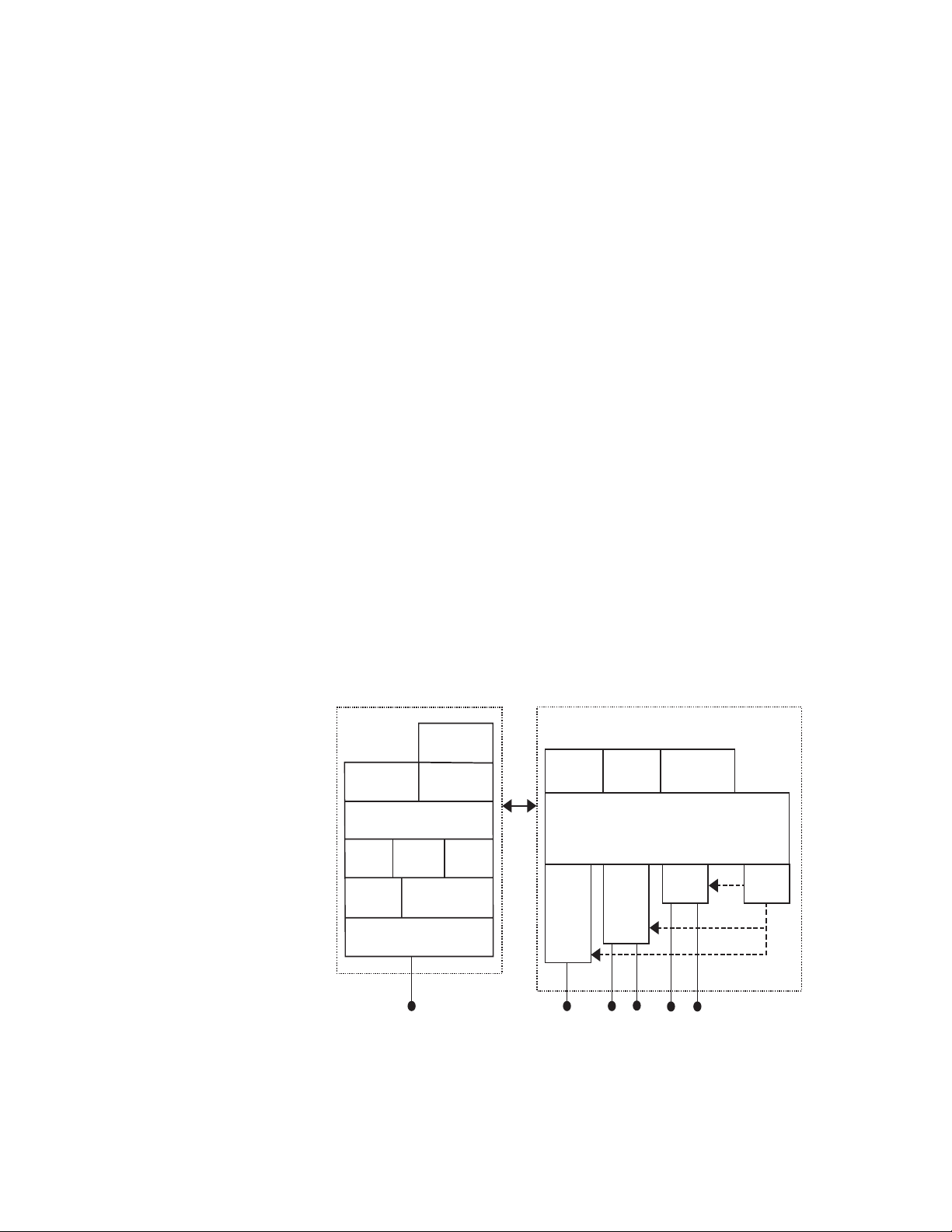
AT-WL2411 Version 1.80 Installation and User’s Guide
s
About the Root
Access Point
The root access point is always on the primary LAN and initiates the
spanning tree. The root coordinates the network and distributes global
system parameters to other access points. The root is elected from a
group of access points that are designated as root candidates (access
points that are powered on, active, and do not have a root priority of 0).
The access point with the highest root priority is the root.
The election process also occurs in the event of a root access point
failure. Besides the root, you should have two or three access points with
a non-zero root priority. If two access points have the same root priority,
the access point with the highest Ethernet address becomes the root.
You should configure your network with overlapping coverage so that
the network can automatically recover from any single point of failure.
After the root access point is elected, it transmits hello messages on all
enabled ports. The spanning tree forms as other access points receive
hello messages and attach to the network on the optimal path to the
root. A non-root access point also transmits hello messages after it is
attached to the network. Each hello message contains the LAN ID of the
access point that originated the message. The protocol does not allow
wireless links to exist between access points that do not have matching
LAN IDs.
About Bridging Wireless end devices operate similarly to other Ethernet products;
therefore, all of your existing Ethernet applications will work with the
wireless network without any special networking software. Figure 29
shows the general architecture of the access point.
Management and Configuration
MIB
TCP/IP
HTTP
Configuration
Settings
SNMP
Agent
Telnet
DHCP
TFTP
File
System
Configuration Port
RS-232 Connector
Forwarding
Database
Ethernet
Ethernet
Connector
Port
Multiport Bridge
Spanning
Tree
Bridging
Radio
Port 1
Antenna
Connectors
Connectors
Wireless ARP
Server
Radio
Port 2
Antenna
IP
Port
21XXT034.ep
Figure 29 General Architecture of the Access Point
81
Page 82

Configuring the Spanning Tree
By default, wireless traffic is not bridged to a remote IP subnet. Any
access point on a remote subnet that can receive IP hello messages can
establish an IP tunnel; therefore, multiple IP tunnels can exist between
the root access point and a single remote IP subnet.
If bridging is disabled, all traffic for end devices is forwarded between
access points using data link encapsulation, which means that the MAC
source/destination addresses correspond to the access points
originating/receiving the traffic for the end devices. By using data link
encapsulation, you prevent network monitoring tools and other
network components from detecting end device MAC/IP addresses that
belong to the remote subnet. It is strongly recommended that you use
the default setting when you are using IP tunnels to provide mobility of
other routable protocols, such as IPX. In some network installations,
detecting these addresses may generate alarms or cause switches to
behave erroneously. There is no additional forwarding overhead for
disabling bridging in this situation.
If you enable bridging on a remote subnet, a single access point
functions as the designated bridge for the secondary LAN. In this case,
only the designated bridge can establish an IP tunnel. Any other access
point on the remote subnet must attach to the network through the
designated bridge. End device MAC/IP addresses are fully visible on the
remote subnet. If you are using IP tunnels to provide mobility for IP and
other non-routable protocols, you can enable bridging on remote IP
subnets, because IP has built-in safeguards and filters for protecting the
operation of IP routers and other network components.
Also, you should enable bridging if the root access point and the
gateway that supports the NNL devices are on different IP subnets. You
may also need to enable bridging if your wireless end devices use
terminal emulation running the NNL protocol or if you use wireless end
devices that are running both IP and NNL.
82
Page 83

AT-WL2411 Version 1.80 Installation and User’s Guide
Bridging Layer
Functions
Some of the significant functions supported at the bridging layer are
explained below.
Network Organization
Access points automatically configure into a self-organized network
using a spanning tree topology. As devices are added to or removed
from the network, the access points automatically reconfigure to
maintain reliable operation. The spanning tree provides efficient, loopfree forwarding of frames through the network and allows rapid
roaming of end devices.
The root access point initiates the spanning tree. The root coordinates
the network and distributes common system parameters to other access
points and wireless end devices. The root is elected from a group of
access points that are designated as root candidates at the time of
installation. The election process also occurs in the event of a root
failure. You can configure your network with overlapping coverage so
that the network automatically recovers from any single point of failure.
End devices can optionally participate in the spanning tree protocol by
explicitly attaching to the network. As a result, operational parameters
are easily distributed, unicast flooding is reduced or eliminated, and
roaming hands-off logic is more robust.
Forwarding
The access point maintains a forwarding database of all physical station
addresses, and it knows the correct port for each address. The access
point updates this database by monitoring source addresses on each
port (backward learning), by receiving explicit attachment messages,
and by examining messages exchanged between access points when
wireless end devices roam. The database also includes the power
management status of each end device, which allows the access point to
support the pending message feature of the network. The forwarding
database allows the bridging software to make efficient forwarding
decisions.
83
Page 84

Configuring the Spanning Tree
Switch Support
Ethernet switches that do not comply with the 802.1D standard have
difficulty handling wireless end devices that roam between different
switched segments. The access point provides data link tunneling for
switches that do not handle roaming. Using data link tunneling, frames
for a given end device always appear on the root access point’s switched
segment, regardless of roaming, and the switch’s routing tables remain
stable.
Flooding Configurations
When the destination address is unknown, standard LAN bridges flood
frames on all ports. Most wireless end devices supported by the access
point operate at lower speeds than Ethernet; therefore, indiscriminate
flooding from a busy Ethernet backbone to an end device can consume
a substantial portion of the available wireless bandwidth and reduce
system performance. The access point allows you to set flooding control
options for both unicast and multicast frames to free up bandwidth and
improve system performance.
Pending Messages
Wireless end devices may use power management to maintain battery
life. These end devices wake up periodically to receive frames that
arrived while their radio was powered down. The bridging software in
the access point provides a pending message delivery service that
allows frames to be held until the end device is ready to receive them.
Filtering Options
The access point incorporates extensive filtering capabilities. Basic filters
allow you to filter on DIX type, protocol port, socket, or SAP. Advanced
filters let you create and group filters based on data patterns that you
define.
84
Page 85

AT-WL2411 Version 1.80 Installation and User’s Guide
About
Secondary LANs
and Designated
Bridges
The access point that is responsible for bridging data between the
secondary LAN and the primary LAN is called the designated bridge. In
both types of secondary LANs, the designated bridge acts the same. The
designated bridge must be an access point that has at least one radio set
to Station mode or is the endpoint of an IP tunnel. If more than one
access point meets at least one of these requirements, the access point
with the highest secondary LAN bridge priority is the designated bridge.
If an access point has the highest bridge priority on the secondary LAN,
but it is not in the radio coverage area of an access point on the primary
LAN, it cannot become the designated bridge. In this case, an access
point with a lower bridge priority that is in the radio coverage area or an
access point on the primary LAN becomes the designated bridge. If two
access points have the same secondary LAN bridge priority, the access
point with the highest Ethernet address becomes the designated bridge.
If the designated bridge goes offline, the remaining access points
negotiate to determine which access point becomes the new
designated bridge.
Designated bridges determine if the secondary LAN is bridging or nonbridging. By enabling the Ethernet bridging parameter on the
designated bridge, all wireless traffic gets dumped raw on the secondary
LAN. You should enable bridging if you have wired hosts on the
secondary LAN that must communicate with a wireless device on the
secondary LAN.
You should enable bridging unless the inbound path through a bridge
or switch does not support roaming. Bridges and switches that adhere to
the IEEE 802.1D standard support roaming. Some proprietary VLAN
switches and ATM LANE bridges do not support roaming. If you disable
the Ethernet bridging parameter on the designated bridge, the wireless
traffic is encapsulated on the secondary LAN, which eliminates
communication from secondary LAN end devices.
If you set the secondary LAN bridge priority to 0 on the designated
bridge, you have a non-bridging secondary LAN; that is, bridging to the
secondary LAN is automatically disabled.
85
Page 86

Configuring the Spanning Tree
Configuring Global Parameters
Global parameters are configured on the root access point and on any
other access point that is a root candidate (does not have a root priority
of 0). The root access point sends these settings to all other access points
on the network. You should set the same global parameters for the root
access point and its backup candidates.
Any global parameters you set on the root access point will override
parameters those you set in other access points.
Configuring
Global Flooding
Use global flooding to configure how the access points handle a frame
with an unknown address. Access points try to forward frames to the
port with the shortest path to the destination address. When the access
point has not learned the direction of the shortest path, you can
configure it to flood the frames in certain directions to try to locate the
destination address.
To configure global flooding, perform the following procedure:
1. From the Main Menu, select Spanning Tree Settings then Global
Flooding. The Global Flooding screen as shown in Figure 30 is
displayed.
86
Figure 30 Global Flooding Screen
Page 87

AT-WL2411 Version 1.80 Installation and User’s Guide
2. Configure the Global Flooding parameters. The Global Flooding
Parameters are explained below.
Multicast Flood Mode
Determines the flooding structure for inbound multicast frames
with unknown destination addresses.
Universal
Allows any wireless end device to communicate with any other
wireless end device.
Hierarchical
Allows wireless end devices to communicate with nodes on the
primary LAN but not with other wireless end devices.
Disabled
Prevents flooding.
Multicast Outbound to Terminals
This parameter only applies to 802.11b radios. If multicast flood
mode is not disabled, this parameter specifies if outbound
multicast frames with unknown destination addresses are
flooded toward wireless end devices
Multicast Outbound to Secondary LANs
If multicast flood mode is not disabled, this parameter specifies if
outbound multicast frames with unknown destination addresses
are flooded toward secondary LANs.
Enabled
The root access point controls flooding for all access points
serving as designated bridges for the secondary LANs.
Set locally
Designated bridges for the secondary LANs control flooding on
their LANs.
Unicast Flood Mode
Determines the flooding structure for inbound unicast frames
with unknown destination addresses.
Universal
Allows any wireless end device to communicate with any other
wireless end device.
Hierarchical
Allows wireless end devices to communicate with nodes on the
primary LAN but not with other wireless end devices.
87
Page 88

Configuring the Spanning Tree
Disabled
Prevents flooding.
Unicast Outbound to Terminals
If the unicast flood mode is not disabled, this parameter specifies
if outbound unicast frames with unknown destination addresses
are flooded toward wireless end devices. This parameter only
applies to 802.11b radios.
Unicast Outbound to Secondary LANs
If the unicast flood mode is not disabled, this parameter specifies
if outbound unicast frames with unknown destination addresses
are flooded toward secondary LAN segments.
Enabled
The root access point controls flooding for all access points
serving as designated bridges for the secondary LANs.
Set locally
Designated bridges for the secondary LANs control flooding on
their LANs.
3. Select Submit Changes to save your changes. To activate your
changes, select Save/Discard Changes from the menu bar then Save
Changes and Reboot. For help, see Saving Your Configuration
Changes on page 46.
88
Page 89

AT-WL2411 Version 1.80 Installation and User’s Guide
Configuring
Global RF
Parameters
Use global RF parameters to set various parameters on the access points.
If you are configuring the root access point and you set the Set Globally
parameter to Enabled, the value for that parameter is set globally for all
access points and wireless end devices in the network. If you are
configuring the root access point and you set the Set Globally parameter
to Disabled or if you are not configuring the root access point, each
device uses its local setting.
To configure global RF parameters, perform the following procedure:
1. From the Main Menu, select Spanning Tree Settings then Global RF
Parameters. The Global RF Parameters screen as shown in Figure 31
is displayed.
Figure 31 Global RF Parameters Screen
2. Configure the GLOBAL RF Parameters. Select the links in the Global RF
Parameters Menu to set more parameters. The parameters are
explained below.
89
Page 90

Configuring the Spanning Tree
RFC1042/DIX Conversion
Determines how the access point will handle the conversion of
RFC1042/DIX frames that are received on its 802.11b ports.
Enabled
Causes frames received on an 802.11b port with a protocol type
equal to a value in the “RFC1042 types to pass through” list to be
forwarded without conversion. If the frame has a protocol types
that is not found in the list, it will be converted to DIX format
before it is forwarded.
Disabled
Causes frames received on an 802.11b port to be forwarded
without conversion; that is, when a SNAP frame is received from
an 802.11b radio with an OUI (Organizationally Unique Identifier)
equal to 000000, it will be forwarded without conversion.
RFC1042 Types to Pass Through
If the RFC1042/DIX Conversion field is Enabled, this parameter
specifies values for protocol types that are to be passed without
conversion. The list includes the Apple Talk protocol type, value
80F3.
Values entered in this parameter represent the protocol types of
frames that will be passed without conversion to DIX format.
3. Select Submit Changes to save your changes. To activate your
changes, select Save/Discard Changes from the menu bar then Save
Changes and Reboot. For help, see Saving Your Configuration
Changes on page 46.
90
Page 91

About IP Tunnels
AT-WL2411 Version 1.80 Installation and User’s Guide
The physical boundary of a wireless network is usually defined by the
presence of an IP router. Multiple independent wireless networks may
exist, each with its own LAN ID, root access point, and set of wireless end
devices. In this environment, an end device can only operate within the
limited coverage area of its own network and cannot roam across IP
subnet boundaries. However, using IP tunnel technology, end devices
now can roam across subnet boundaries. This technology is designed to
safely and transparently coexist with routed IP installations while
supporting mobility for end devices. IP tunnels do the following:
❑ Enables access points on different subnets to belong to the same
wireless network.
❑ Supports transparent roaming of end devices between access
points that are on different subnets without losing network
connections.
❑ Supports end devices using both IP and other routable or
nonroutable protocols.
The AT-WL2411 consists of a group of multiport Ethernet-to-wireless
bridges. The IP tunnel port uses a standard IP protocol called Generic
Routing Encapsulation (GRE) to encapsulate a frame. These
encapsulated frames can use normal IP routing to pass through IP
routers. Unlike the physical Ethernet and radio ports, the IP tunnel port
does not have its own output connector. It is a logical port that provides
IP encapsulation services for frames that must be routed to reach their
destinations. Once frames are encapsulated, they are transmitted or
received through a physical port.
In other words, IP tunnels use encapsulation to establish a virtual LAN
segment through IP routers. The virtual LAN segment includes the home
IP subnet and logically extends to include end devices attached to
access points on remote IP subnets. An IP tunnel becomes a branch in
the spanning tree. Access points on remote subnets can be directly
connected to an IP tunnel or indirectly connected through another
access point on a remote subnet.
91
Page 92

Configuring the Spanning Tree
s
An IP Tunnels configuration is shown in Figure 32.
Wireless
stations
Primary LAN
home subnet
IP router
IP network
IP router
UAP 1
(root)
UAP 3
(Designated
Bridge)
UAP 2
UAP 4
Host
UAP 5
Secondary LAN
remote subnet
Wireless
stations
21XXT028.ep
Figure 32 IP Tunnels Configuration
A non-root access point can concurrently receive hello messages on its
Ethernet port, its radio port, and its IP tunnel port. However, an access
point can use only one port to attach to the network. Port priorities are
structured so that an Ethernet connection is always selected first and an
IP tunnel connection is always selected before a radio connection.
Setting the secondary LAN bridge priority to zero disables the bridging
of wireless traffic to remote IP subnets. It allows end devices that are
connected to access points on a remote IP subnet to communicate with
hosts on the home subnet without bridging wireless traffic to the
remote IP subnet. This is always done for IP communication since the
wireless traffic is always from the home subnet and not from the remote
subnet. The secondary LAN bridge priority will allow you to select the
bridging mode for non-IP traffic such as NNL.
92
Page 93

AT-WL2411 Version 1.80 Installation and User’s Guide
Internet Group
Management
Protocol (IGMP)
IGMP lets you originate multiple IP tunnels using a single IP multicast
address. Note that IGMP is independent of IP; it can be used to facilitate
multicast for IP or any other application.
IP routers only forward multicast packets to those subnets that have IP
hosts that participate in the respective IP multicast group. An IP host
uses IGMP to notify IP routers that it wants to participate in an IP
multicast group. Access points can act as IP hosts and participate in an IP
multicast group by enabling IGMP and by defining a Class D IP multicast
address. The Internet Assigned Numbers Authority has allocated
224.0.1.65 as an inter-access-point protocol (IAPP). You must enter this
address in the IP address list in the root access point. (Note that the
address list may contain other IP addresses.) and in the Multicast
Address field in the other access points.
If you enable IGMP on the root access point, the root access point uses a
Class D IP multicast address to send IP hello packets through IP routers
to access points on other subnets. If you enable IGMP on remote IP
subnets, intermediate IP routers will forward the IP hello packets to
those subnets. Enabling IGMP also has these advantages:
❑ Causes IP hello packets to be forwarded only to those subnets that
participate in the IP multicast group.
❑ Increases redundancy because multiple access points on a remote
subnet can receive IP hello packets.
IP multicast provides an ideal way to distribute IP hello messages.
Normally, you should enable IGMP and configure an IP multicast address
in at least one access point on each remote IP subnet. (Some routers can
provide proxy IGMP services for IP hosts.) IP multicast has the following
advantages:
❑ The user does not have to know unicast or directed broadcast IP
addresses in advance.
❑ IP multicast provides better built-in redundancy than IP unicast,
because any access point can establish an IP tunnel.
IP hello messages are only forwarded to those IP subnets and IP hosts
(such as access points) that participate in the multicast group. Directed
broadcast packets are forwarded to all IP hosts on the target subnet.
93
Page 94

Configuring the Spanning Tree
Originating IP
Tunnels
The creation of tunnels between the root access point on the home IP
subnet and access points on remote IP subnets is controlled by three
operational parameters:
❑ Enabled/disabled IP ports. A tunnel can never be established on a
disabled IP port.
❑ IP address list
❑ Secondary LAN bridge priority settings
An IP tunnel is established when an access point on a remote IP subnet
attaches to the root access point through its IP tunnel port. The number
of IP tunnels the root access point can originate is practically unlimited.
However, the IP address list can presently contain eight entries. The size
of the address list effectively limits the number of tunnels that can be
created if unicast and directed broadcast IP addresses are used;
however, you can use a single IP multicast address to originate a
practically unlimited number of tunnels.
The IP address list can contain any combination of IP unicast, IP
broadcast, or IP multicast addresses. Only one IP tunnel can be created
for each IP unicast address in the list. A single IP multicast address can be
used to create a practically unlimited number of tunnels to multiple
remote IP subnets. A single IP directed broadcast address can be used to
create a practically unlimited number of tunnels to a single remote IP
subnet. (An IP directed broadcast address is typically used to specify all
hosts on a single remote subnet.)
A remote IP subnet functions much like a wireless secondary LAN with
these exceptions:
❑ Any access point can provide a wireless link to another access
point. Only the root access point can originate an IP tunnel.
❑ A wireless link can provide a transparent bridge for both wired
and wireless devices on a wireless secondary LAN. An IP tunnel
only provides a transparent bridge for end devices (unless
explicitly configured to provide connectivity for an NNL gateway
on a remote IP subnet).
94
Page 95

AT-WL2411 Version 1.80 Installation and User’s Guide
Establishing
and
Maintaining IP
Tunnels
IP Addressing
for End Devices
If the IP tunnel port control is enabled, the root access point sends hello
messages to each IP address in its IP address list. An access point on a
remote IP subnet automatically establishes an IP tunnel if it receives an
IP hello message from the root access point. An access point attached
through an IP tunnel transmits hello messages on the remote subnet so
that other access points on the remote subnet that do not receive IP
hello messages can also attach to the network.
If IP hello messages are sent to IP unicast addresses, then some access
points on a remote subnet will not receive hello messages; therefore,
those access points cannot establish an IP tunnel. If bridging is disabled
on the subnet, wireless traffic is forwarded to and from these access
points through data link tunnels. A data link tunnel is logically
concatenated with an IP tunnel so that wireless traffic can be completely
isolated from the remote IP subnet.
If you need to bridge to a remote subnet, see Configuring the Spanning
Tree Parameters on page 78.
IP end devices must be assigned IP addresses that are on the home IP
subnet. There are no address restrictions for non-IP end devices.
Using Non-IP
Protocols
Servers that use a routable network protocol such as IP or IPX may be
located on any subnet; however, triangular routing can be minimized if
servers are located on the home IP subnet. (Note that this is also true for
standard mobile IP.) You should be able to use default flooding and
bridging settings if you are using routable protocols, even if servers are
located on remote IP subnets.
The NNL protocol is a simple Non-routable Network Layer protocol that
is used to carry high-layer data in a local area network environment. An
NNL gateway forwards NNL traffic to non-NNL hosts such as TCP/IP
hosts. You can use the default flooding and bridging settings, and
minimize triangular routing, if NNL gateways are located on the home
subnet. If NNL gateways are located or remote subnets, you must enable
outbound multicast flooding and secondary bridging.
95
Page 96

Configuring the Spanning Tree
Frame
Forwarding
Any data packet sent through an IP tunnel is addressed to the unicast IP
address of the access point at the other end of the tunnel. An access
point at the remote end of the tunnel learns the unicast IP address of the
root access point by listening to IP hello packets. The root access point
learns the unicast IP address of a remote access point when the access
point attaches to the network.
Usually, ARP requests (which are multicast packets) that originate on the
home IP subnet are forwarded outbound to all devices on the network,
including through IP tunnels to remote IP subnets. If you configure the
access point as an ARP server, ARP packets are only sent through the IP
tunnel to the destination end device.
Unicast frames are only forwarded outbound through an IP tunnel if the
destination address identifies an end device that has roamed to a
remote IP subnet. Usually, wireless traffic is not bridged to remote IP
subnets and traffic from a remote IP subnet is never forwarded inbound
through an IP tunnel.
MAC frames originating on the home IP subnet are encapsulated in the
root access point, forwarded through the IP network, unencapsulated by
the access point at the remote end of the IP tunnel, and forwarded to the
appropriate access point (if necessary) for delivery to the destination
end device. For inbound frames, the same process is used in reverse
between the access point at the remote end of an IP tunnel and the root
access point.
Certain frame types are never forwarded through tunnels. Frame types
that are never forwarded include IP frames used for coordinating routers
and MAC frames used for coordinating bridges. Frame types that are
never forwarded include:
❑ 802.1D bridge frames
❑ Proprietary VLAN switch frames
❑ IP frames with a broadcast or multicast Ethernet address
❑ IP frames with the following router protocol types and decimal
values:
— DGP (86) (Dissimilar Gateway Protocol)
— EGP (8) (Exterior Gateway Protocol)
— IDPR (35) (Inter-Domain Policy Routing Protocol)
— IDRP (45) (Inter-Domain Routing Protocol)
— IGP (9) (Interior Gateway Protocol)
96
Page 97

AT-WL2411 Version 1.80 Installation and User’s Guide
—IGRP (88)
— MHRP (48) (Mobile Host Routing Protocol)
— OSPFIGP (89) (Open Shortest Path First Interior Gateway
Protocol)
❑ IP ICMP (Internet Control Message Protocol) types:
—IPv6
— Mobile IP
— Router Advertisement
— Router Selection
❑ IP/UDP (User Datagram Protocol) frames with the following
destination protocol port numbers:
— BGP (179) (Border Gateway Protocol)
— RAP (38) (Route Access Protocol)
— RIP (520) (Routing Information Protocol)
❑ IP/TCP frames with the following destination or source protocol
port numbers:
— BGP (179) (Border Gateway Protocol)
— RAP (38) (Route Access Protocol)
Outbound Frames
Data frames are forwarded outbound through an IP tunnel if
❑ an end device is known to be attached to an access point on a
remote IP subnet.
❑ the frame type is enabled in the Tunnel Filters menu.
Unicast frames are not flooded. End devices attach to the root access
point, which maintains entries for these devices in its forwarding
database. The database entries indicate the correct subnet for outbound
forwarding.
For TCP/IP applications, IP and ARP frames must be forwarded through
IP tunnels. An IP or ARP frame is only forwarded outbound if the
destination address identifies an end device on the home IP subnet. If
you enable the ARP server in the root access point, you can reduce the
number of ARPs forwarded outbound.
97
Page 98

Configuring the Spanning Tree
Inbound Frames
Only frame types that are enabled in the Tunnel Filters menu are
forwarded, and the frames are only forwarded inbound if the source IP
address belongs to the home IP subnet. Frames transmitted by servers
or devices that are wired to a remote IP subnet are not forwarded
through IP tunnels if the IP address does not belong to the home subnet.
Only frames from wireless end devices with IP addresses belonging to
the home subnet are forwarded inbound.
Configuring IP
Tunnels
In general, here are some guidelines you can use to configure IP tunnels:
❑ When choosing the home IP subnet, ideally you should choose
the subnet that contains gateways or servers for end devices;
however, these servers may be on other subnet. Note that you can
create a home subnet for end devices. Fixed or variable length
subnet masks can be used; subnet addressing is not required. IP
addresses for end devices must belong to the home subnet.
❑ Identify the root candidates on the home subnet. The root access
point should be an access point that does not otherwise handle a
large volume of traffic.
❑ Configure all access points on the home subnet and remote IP
subnets with the same LAN ID. If IP tunnels are not used to attach
a remote subnet, then access points on that subnet should be
configured with a different LAN ID.
❑ In the IP Tunnels screen, enable the Port Control parameter in all
access points that are root candidates and designated bridge
candidates.
❑ In the IP Tunnels screen, configure the Mode parameter in root
candidates to Originate if Root. Configure the Ethernet Address
table to include access points on each remote subnet. All root
candidates should be configured identically.
98
❑ In the IP Tunnels screen, configure the Mode parameter in
designated bridge candidates to Listen.
Page 99

AT-WL2411 Version 1.80 Installation and User’s Guide
❑ In the Tunnel Filters screen, configure the filters in root candidates
and in other access points that can be attached through an IP
tunnel. IP tunnel filters are consistent with Ethernet filters.
❑ For networks using IP networking on end devices, it is
recommended that you enable the ARP server capability in the
access points.
❑ Determine if you need to enable bridging on remote subnets. For
example, bridging must be enabled if an NNL gateway is attached
to the remote subnet. For help, see Configuring the Spanning
Tree Parameters on page 78. The designated bridge candidates
must have permanent IP addresses and must be able to receive IP
hello messages from the root access point. An access point will
receive IP hello messages if the messages are sent to the unicast
IP address of the access point, or to an IP-directed broadcast or IP
multicast address. Note you may need to enable IGMP for IP
multicast.
To configure the IP Tunnels screen, perform the following procedure:
1. From the Main Menu, select IP Tunnels. The IP Tunnels screen as
shown in Figure 33 is displayed.
Figure 33 IP Tunnels Screen
99
Page 100

Configuring the Spanning Tree
2. Select the down arrow on the right side of the Mode field and choose
Originate if Root to let the access point originate the tunnel if it is
functioning as the root access point for the network.
a. Choose Disabled if you do not want this access point to
participate in IP tunnels.
b. Chose Listen to configure access points that are designated
bridges or designated bridge candidates for their remote IP
subnet to serve as the endpoint of an IP tunnel.
3. Check or uncheck the box on the right side of the Enable IGMP to
Enabled or Disabled this feature.
Note
If you enable IGMP on the root access point, you need to enter the
Class D IP multicast address in the IP address list. For help, refer to
Configuring IP Address List on page 101.
4. Select Submit Changes.
5. In the Multicast Address field, enter the multicast address. Unless
you have your own IP multicast address, the Internet Assigned
Numbers Authority has allocated 224.0.1.65 for the inter-access-point
protocol (IAPP). You should use this default multicast address.
6. Select Submit Changes to save your changes. To activate your
changes, select Save/Discard Changes from the menu bar then Save
Changes and Reboot. For help, see Saving Your Configuration
Changes on page 46.
100
 Loading...