

Page 1

USB 2.0
Wireless
Adapter
AT-WCU201G
Installation Guide
613-000260 Rev. A
Page 2

Copyright © 2005 Allied Telesyn, Inc.
All rights reserved. No part of this publication may be reproduced without prior written permission from Allied Telesyn, Inc.
Microsoft and Internet Explorer are registered trademarks of Microsoft Corporation. Netscape Navigator is a registered trademark of
Netscape Communications Corporation. All other product names, company names, logos or other designations mentioned herein are
trademarks or registered trademarks of their respective owners.
Allied Telesyn, Inc. reserves the right to make changes in specifications and other information contained in this document without prior
written notice. The information provided herein is subject to change without notice. In no event shall Allied Telesyn, Inc. be liable for any
incidental, special, indirect, or consequential damages whatsoever, including but not limited to lost profits, arising out of or related to this
manual or the information contained herein, even if Allied Telesyn, Inc. has been advised of, known, or should have known, the possibility
of such damages.
Page 3

AT-WCU201G Wireless Adapter Card Installation Guide
Regulatory Notes and Statements
Wireless LAN,
Health and
Authorization For
Use
Regulatory
Information and
Disclaimers
Radio frequency electromagnetic energy is emitted from Wireless LAN
devices. However, the energy levels of these emissions are far less than
the electromagnetic energy emissions from similar wireless devices such
as mobile phones. Wireless LAN devices are safe for use with frequency
safety standards and recommendations. The use of Wireless LAN devices
may be restricted in some situations or environments for example:
❑ On board airplanes
❑ In an explosive environment
❑ If the interference risk to other devices or services is perceived or
identified as harmful
If the policy regarding the use of Wireless LAN devices in specific
organizations or environments (for example, airports, hospitals,
chemical/oil/gas industrial plants, or private buildings, etc.) is not clear,
please ask for authorization to use these devices prior to operating the
equipment.
Installation and use of this Wireless LAN device must be in strict
accordance with the instructions included in the user documentation
provided with the product. Any changes or modifications made to this
device that are not expressly approved by the manufacturer may void
the user’s authority to operate the equipment. The Manufacturer is not
responsible for any radio or television interference caused by
unauthorized modification of this device, of the substitution or
attachment. The manufacturer and its authorized resellers or distributors
will assume no liability for any damage or violation of government
regulations arising from failing to comply with these guidelines.
USA-FCC
(Federal
Communications
Commission)
Statement
This device complies with Part 15 of FCC Rules. Operation of this device
is subject to the following two conditions:
❑ This device may not cause harmful interference
❑ This device must accept any interference received, including
interference that may cause undesired operations.
3
Page 4

Regulatory Notes and Statements
CE Caution
European standards dictate the maximum radiated transmit power of
100mW EIRP and a frequency range of 2.400-2.4835GHz (channels 1 -13).
In France, the equipment must be restricted to the 2.4465-2.4835GHz
(channels 10 -13) frequency range and must be restricted to indoor use.
The following equipment: AT-WCU201G 54Mbps Wireless USB 2.0
Adapter.
Is herewith confirmed to comply with the requirements set out in the
Council Directive on the Approximation of the Laws of the Member
States relating to the Electromagnetic Compatibility (89/336/EEC). Lowvoltage Directive (72/23/ECC) and the Amendment Directive
(93/68/EEC), the procedures given in European Council Directive
99/5/EC and 89/3360EEC.
The equipment passed. The test was performed according to the
following European standards:
FCC Radio
Frequency
Exposure
Statement
FCC Interference
Statement
❑ EN 300 328 V.1.4.1 (2003-04)
❑ EN 301 489-1 V.1.3.1 (2001-09) / EN 301 489-17 V.1.1.1 (2000-09)
❑ EN 50371: 2002
❑ EN 60950: 2000
This Wireless LAN radio device has been evaluated under FCC Bulletin
OET 65 and found compliant to the requirements as set forth in CFR 47
Sections 2.1091, 2.1093, and 15.247 (b) (4) addressing RF Exposure from
radio frequency devices.
FCC RF Radiation Exposure Statement: This equipment complies with
the FCC RF radiation limits set forth for an uncontrolled environment.
This device and its antenna must not be co-located or operating in
conjunction with any other antenna or transmitter.
This equipment has been tested and found to comply with the limits for
a Class B digital device, pursuant to Part 15 of the FCC Rules. These limits
are designed to provide reasonable protection against harmful
interference in a residential installation.
This equipment generates, uses, and can radiate radio frequency energy.
If not installed and used in accordance with the instructions, it may
cause harmful interference to radio communications.
4
Page 5

AT-WCU201G Wireless Adapter Card Installation Guide
However, there is no guarantee that interference will not occur in a
particular installation. If this equipment does cause harmful interference
to radio or television reception, which can be determined by turning the
equipment off and on, the user is encouraged to try and correct the
interference by one or more of the following measures:
❑ Reorient or relocate the receiving antenna.
❑ Increase the distance between the equipment and the receiver.
❑ Connect the equipment to an outlet on a circuit different from
that to which the receiver is connected.
❑ Consult the dealer or an experienced radio/TV technician for help.
Warning
In Canada, the equipment must be restricted to indoor use.
Export
Restrictions
CE Mark
Warning
This product or software contains encryption code that may not be
exported or transferred from the US or Canada without an approved US
Department of Commerce export license.
Safety Information
Your device contains a low power transmitter. When device is
transmitted it sends out radio frequency (RF) signal.
This is a Class B product. In a domestic environment, this product may
cause radio interference, in which case the user may be required to take
adequate measures.
Protection Requirements for Health and Safety - Article 3.1a
Testing for electric safety according to EN60950 has been conducted.
These are considered relevant and sufficient.
Protection Requirements for Health and Safety - Article 3.1b
Testing for electromagnetic compatibility according to EN301 489-1,
EN301 489-17 and EN55024 has been conducted. These are considered
relevant and sufficient.
Effective Use of the Radio Spectrum - Article 3.2
Testing for radio test suites according to EN300 328-2 has been
conducted. These are considered relevant and sufficient.
5
Page 6

Regulatory Notes and Statements
6
Page 7

Contents
Regulatory Notes and Statements .................................................................................................................................... 3
Preface ................................................................................................................................................................................. 9
Document Conventions ....................................................................................................................................................... 10
Where to Find Web-based Guides ...................................................................................................................................... 11
Contacting Allied Telesyn .................................................................................................................................................... 12
Online Support ..............................................................................................................................................................12
Email and Telephone Support .......................................................................................................................................12
Returning Products........................................................................................................................................................12
For Sales or Corporate Information...............................................................................................................................12
Adapter Card Driver Updates ........................................................................................................................................12
Chapter 1: Installing the AT-WCU201G Wireless Adapter Card ................................................................................... 13
Features .............................................................................................................................................................................. 14
LEDs.................................................................................................................................................................................... 15
Reviewing the Package Contents........................................................................................................................................ 16
Installing the Adapter Driver ................................................................................................................................................ 17
Setting the Regulatory Domain............................................................................................................................................ 21
Verifying the Driver Installation............................................................................................................................................ 26
Removing the Adapter Driver .............................................................................................................................................. 27
Chapter 2: Using the Adapter’s Configuration Utility ................................................................................................... 29
Installing the Configuration Utility ........................................................................................................................................ 30
Starting the Configuration Utility .......................................................................................................................................... 35
Creating a Preferred WLAN Profile...................................................................................................................................... 38
No Security....................................................................................................................................................................40
WEP Security ................................................................................................................................................................40
WPA/WPA2-PSK Security..........................................................................................................
Configuring the IP Address.................................................................................................................................................. 45
Deleting a Preferred WLAN Profile...................................................................................................................................... 48
Importing and Exporting Preferred WLAN Profiles.............................................................................................................. 49
Exporting a Preferred WLAN Profile..............................................................................................................................49
Importing a Preferred WLAN Profile..............................................................................................................................50
Working with Profile Groups ................................................................................................................................................ 52
Creating a Profile Group................................................................................................................................................52
Moving a Preferred WLAN Profile .................................................................................................................................53
Renaming a Group ........................................................................................................................................................53
Deleting a Group ...........................................................................................................................................................54
Selecting the Active Profile Group.................................................................................................................................55
Chapter 3: Microsoft Windows XP .................................................................................................................................. 57
Setting the IP Address......................................................................................................................................................... 58
Quick Configuration ............................................................................................................................................................. 62
Manually Configuring the Wireless Adapter......................................................................................................................... 65
No Security....................................................................................................................................................................67
WEP Security ................................................................................................................................................................67
WPA/WPA2-PSK Security.............................................................................................................................................68
Appendix A: Technical Specifications ............................................................................................................................ 69
...................................42
Appendix B: Regulatory Domains ................................................................................................................................... 71
7
Page 8

Contents
8
Page 9

Preface
This guide contains the installation instructions for the AT-WCU201G USB
2.0 wireless network adapter card.
This preface contains the following sections:
“Document Conventions” on page 10
“Where to Find Web-based Guides” on page 11
“Contacting Allied Telesyn” on page 12
9
Page 10
Preface
Document Conventions
This guide uses the following conventions:
Note
Notes provide additional information.
Caution
Cautions inform you that performing or omitting a specific action
may result in equipment damage or loss of data.
Warning
Warnings inform you that performing or omitting a specific action
may result in bodily injury.
10
Page 11

Where to Find Web-based Guides
The installation and user guides for all Allied Telesyn products are
available in Portable Document Format (PDF) from our web site at
www.alliedtelesyn.com. You can view the documents on-line or
download them onto a local workstation or server.
AT-WCU201G Wireless Adapter Card Installation Guide
11
Page 12

Preface
Contacting Allied Telesyn
This section provides Allied Telesyn contact information for technical
support as well as sales or corporate information.
Online Support You can request technical support online by accessing the Allied Telesyn
Knowledge Base from the following web site: www.alliedtelesyn.com/kb.
You can use the Knowledge Base to submit questions to our technical
support staff and review answers to previously asked questions.
Email and
Telephone
Support
Returning
Products
For Sales or
Corporate
Information
Adapter Card
Driver Updates
For Technical Support via email or telephone, refer to the Support &
Services section of the Allied Telesyn web site: www.alliedtelesyn.com.
Products for return or repair must first be assigned a Return Materials
Authorization (RMA) number. A product sent to Allied Telesyn without a
RMA number will be returned to the sender at the sender’s expense.
To obtain a RMA number, contact Allied Telesyn’s Technical Support at
our web site: www.alliedtelesyn.com.
You can contact Allied Telesyn for sales or corporate information at our
web site: www.alliedtelesyn.com. To find the contact information for your
country, select Contact Us -> Worldwide Contacts.
You can download new releases of network adapter card drivers from
either of the following Internet sites:
❑ Allied Telesyn web site: www.alliedtelesyn.com
❑ Allied Telesyn FTP server: ftp://ftp.alliedtelesyn.com
12
To download new firmware from the Allied Telesyn FTP server at your
workstation’s command prompt, you need FTP client software and must
log in to the server. Enter “anonymous” as the user name and your email
address for the password.
Page 13
Chapter 1
Installing the AT-WCU201G Wireless Adapter Card
This chapter contains the installation instructions for the AT-WCU201G
wireless network adapter card. Sections in the chapter include:
“Features” on page 14
“LEDs” on page 15
“Reviewing the Package Contents” on page 16
“Installing the Adapter Driver” on page 17
“Setting the Regulatory Domain” on page 21
“Verifying the Driver Installation” on page 26
“Removing the Adapter Driver” on page 27
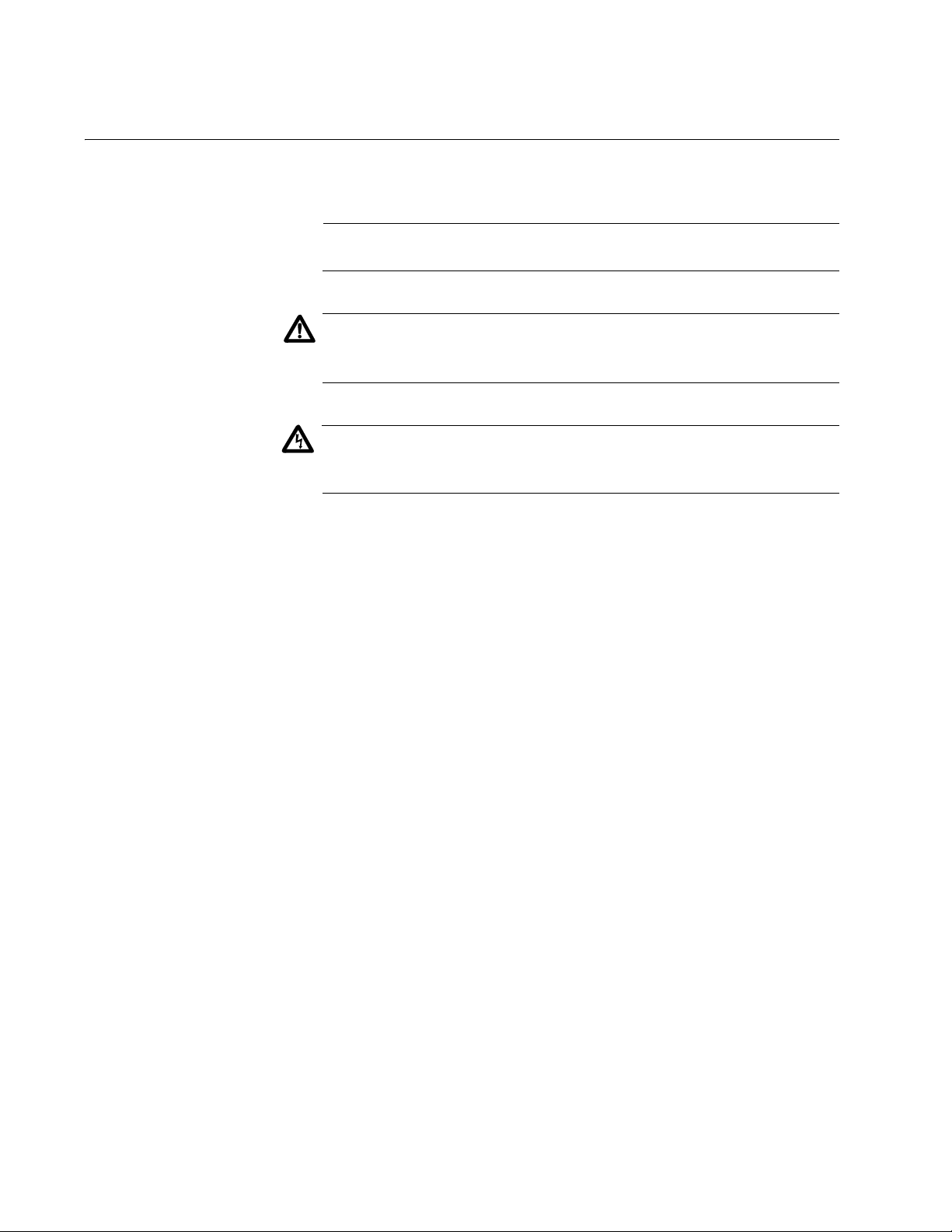
The AT-WCU201G wireless adapter is shown in Figure 1.
Act Link
Act Link
eless USB 2.0
AT-WCU201G
Wir
767
Figure 1. AT-WCU201G Wireless Adapter
13
Page 14

Chapter 1: Installing the AT-WCU201G Wireless Adapter Card
Features
USB 2.0 compliant interface
IEEE 802.11b and 802.11g compliant
6, 9, 12, 18, 24, 36, 48, and 54 Mbps dynamic transmission rates for
IEEE 802.1g
1, 2, 5.5, and 11 Mbps dynamic transmission rates for IEEE 802.1b
Microsoft Windows 2000 and XP compatible
2.4 ~ 2.5 GHz frequency band
Infrastructure and Ad-hoc network compatible
Wired Equivalent Privacy (WEP) with 64, 128, and 152-bit encryption
Wi-Fi Protected Access (WPA) and Wi-Fi Protected Access 2 (WPA2)
Preshared Key (PSK)
WPA Extensible Authentication Protocol (EAL) and WPA2-EAL
Extensible Authentication Protocol (EAP) authentication types —
Transport Layer Security (TLS), Message Digest-5 Challenge
Handshake Authentication Protocol (MD-5 CHAP), and Protected EAP
(PEAP)
Temporal Key Integrity Protocol (TKIP)
Advanced Encryption Standard (AES)
Built-in dual diversity antenna
Super G mode with 108 Mbps transmission rate (Only supported with
wireless routers and access points that feature Super G)
14
Page 15

LEDs
AT-WCU201G Wireless Adapter Card Installation Guide
The two LEDs on the AT-WCU201G adapter are defined in Table 1.
Table 1. LED Descriptions
LED State Description
Link On The adapter is receiving power.
Off The adapter is not receiving
power.
Act On The adapter has established a
connection to a wireless router or
access point. If the LED is
blinking, the adapter is
transmitting or receiving traffic.
Off The adapter has not established a
connection to a wireless router or
access point.
15
Page 16

Chapter 1: Installing the AT-WCU201G Wireless Adapter Card
Reviewing the Package Contents
The shipping package should contain the following items. If any item is
missing or damaged, contact your Allied Telesyn sales representative for
assistance:
AT-WCU201G Wireless Adapter
Software and Documentation CD
USB cable (1 meter)
Warranty card
16
Page 17
Installing the Adapter Driver
To install the adapter driver, perform the following procedure:
1. Power ON the computer.
2. Insert the Software and Documentation CD into the CD drive of the
computer.
Note
If your computer launches the web browser when you insert the CD,
minimize or close the web browser window.
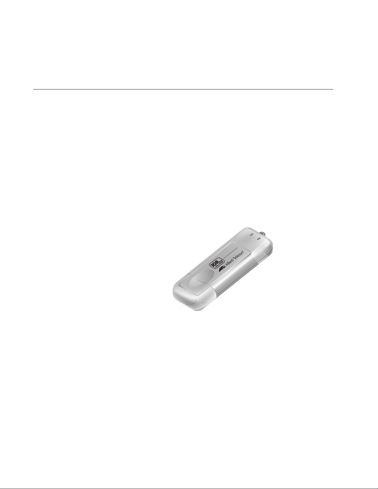
3. Remove the cap from the AT-WCU201G wireless adapter, as shown in
Figure 2.
AT-WCU201G Wireless Adapter Card Installation Guide
Act Link
Act Link
0
eless USB 2.
AT-WCU201G
Wir
768
Figure 2. Removing the Cap from the AT-WCU201G Wireless Adapter
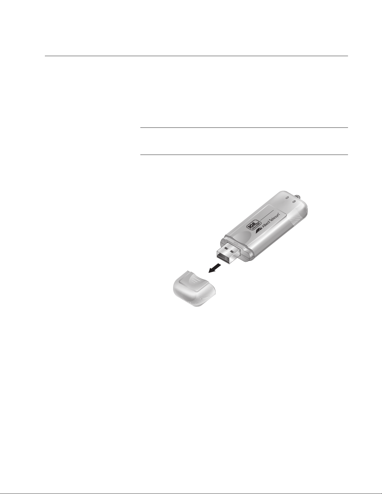
4. Connect one end of the USB cable included with the adapter to a USB
port on your computer. For best performance, the port should be a
USB 2.0 port. The adapter will work if connected to a USB 1.1 port, but
at a reduced speed.
17
Page 18
Chapter 1: Installing the AT-WCU201G Wireless Adapter Card
5. Connect the other end of the cable to the AT-WCU201G wireless
adapter, as shown in Figure 3.
Figure 3. Connecting the AT-WCU201G Wireless Adapter to the USB
Alternatively, you can connect the adapter directly to the USB port on
the computer without the cable.
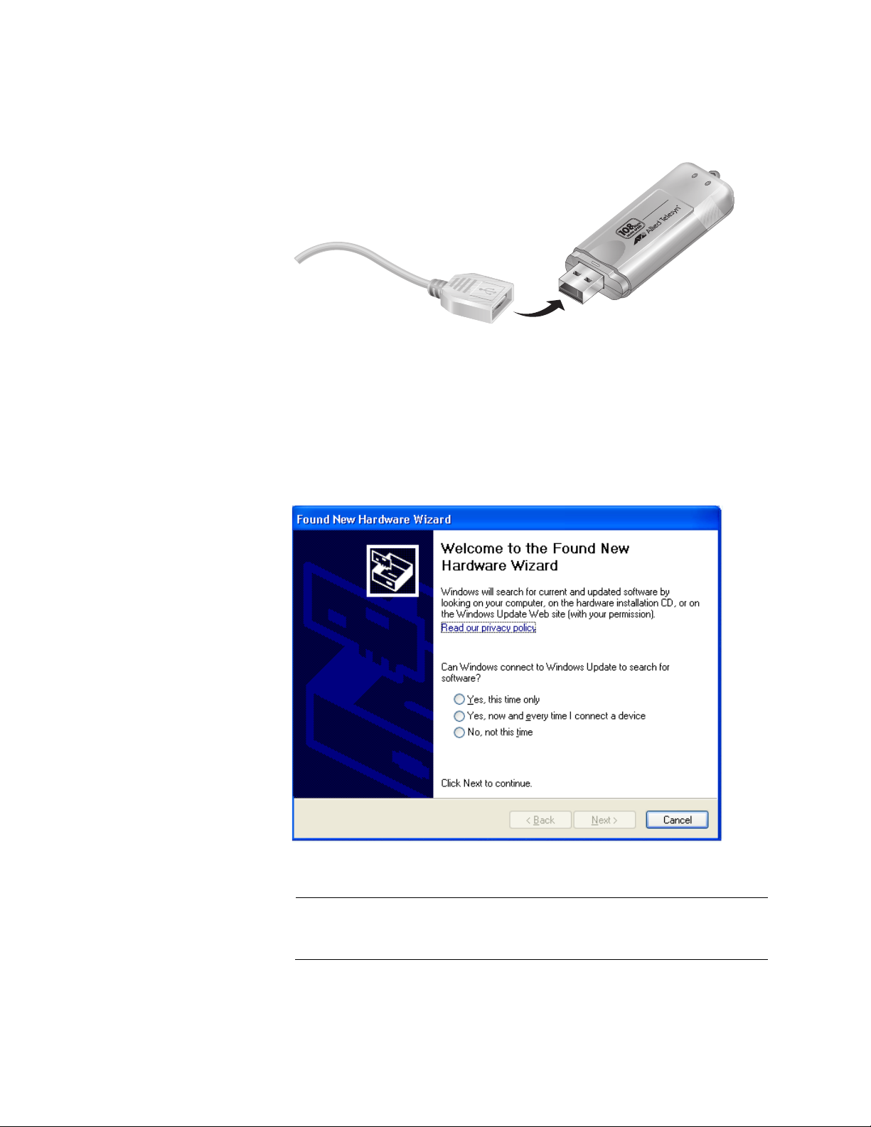
Windows detects the new adapter and launches the Found New
Hardware Wizard. The first window of the wizard is shown in Figure 4.
Cable
eless USB 2.
AT-WCU201G
Wir
0
Act Link
Act Link
769
18
Figure 4. Found New Hardware Wizard Window (1 of 3)
Note
If the window does not appear, disconnect and reconnect the
AT-WCU201G adapter to the computer.
Page 19
AT-WCU201G Wireless Adapter Card Installation Guide
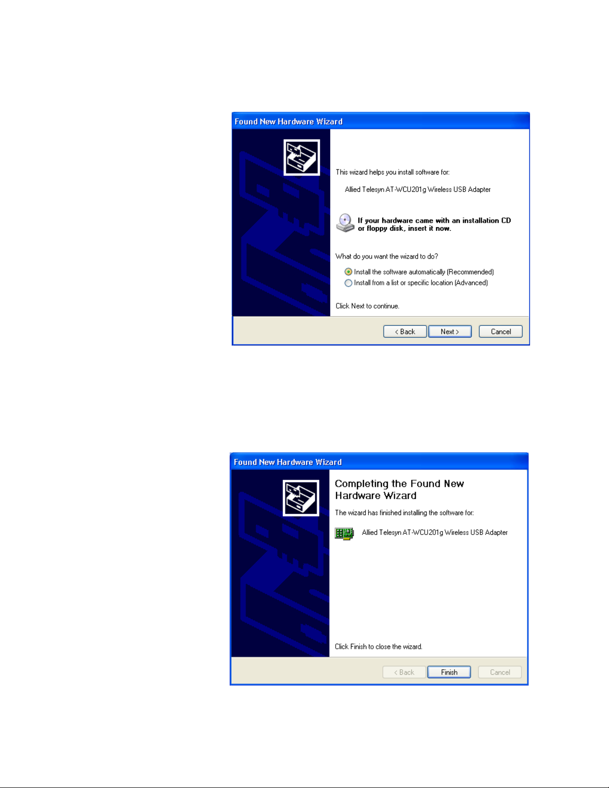
6. In the Found New Hardware Wizard window, select No, not this time
and click Next. The window shown in Figure 5 is displayed.
Figure 5. Found New Hardware Wizard Window (2 of 3)
7. Select Install the software automatically (Recommended) and click
Next.
The following prompt is displayed after the driver is copied to the
computer from the CD.
Figure 6. Found New Hardware Wizard (3 of 3)
19
Page 20

Chapter 1: Installing the AT-WCU201G Wireless Adapter Card
8. Click Finish.
This completes the procedure for installing the adapter driver on a
Microsoft Windows system. Go to the next procedure, “Setting the
Regulatory Domain” on page 21.
20
Page 21
Setting the Regulatory Domain
Caution
The selection of your country or regulatory domain is critical to the
proper operation of the wireless adapter and its adherence to the
laws and regulations that govern the operation of wireless networks
in your country. Failure to select the appropriate country or
regulatory domain can cause the adapter to operate improperly or in
a manner that constitutes a violation of local laws.
To set the regulatory domain, perform the following procedure:
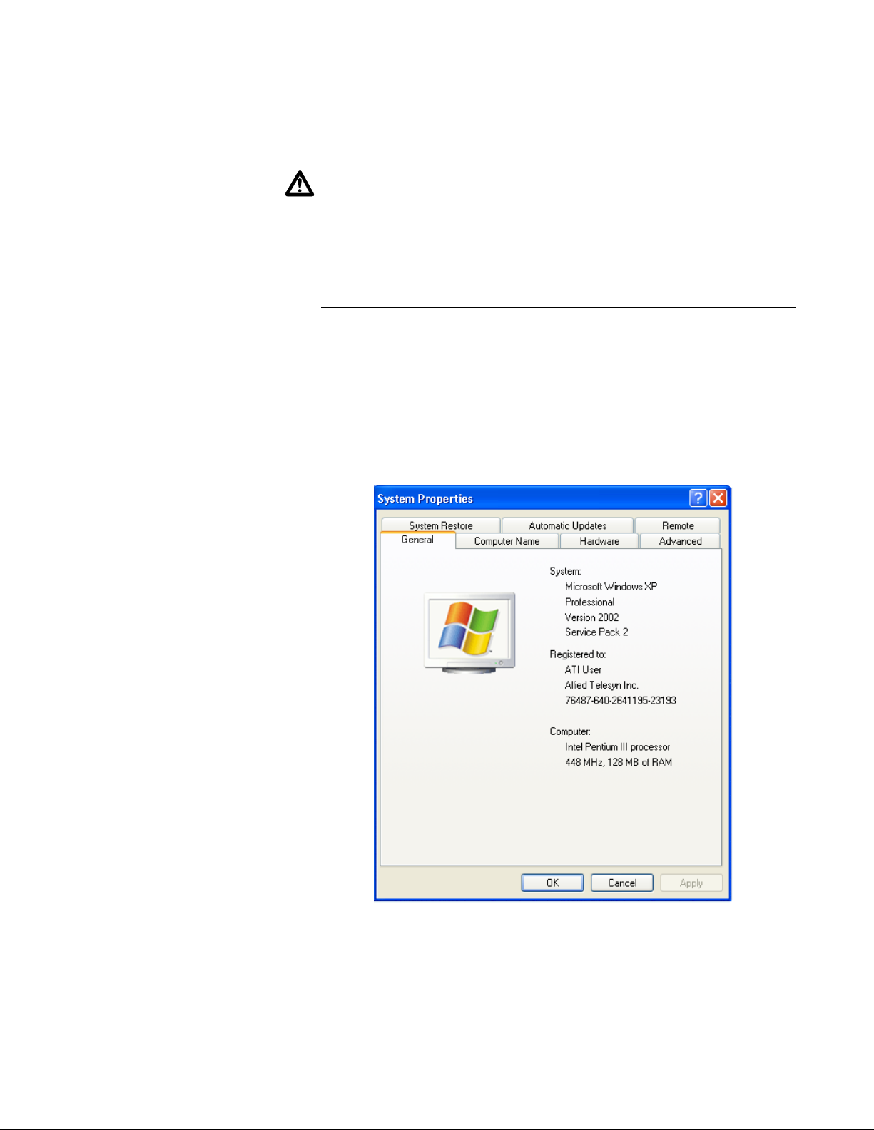
1. Open the Control Panel.
2. Double-click on System.
The System Properties window is shown in Figure 7.
AT-WCU201G Wireless Adapter Card Installation Guide
Figure 7. System Properties Window - General Tab (Microsoft Windows
XP)
21
Page 22
Chapter 1: Installing the AT-WCU201G Wireless Adapter Card
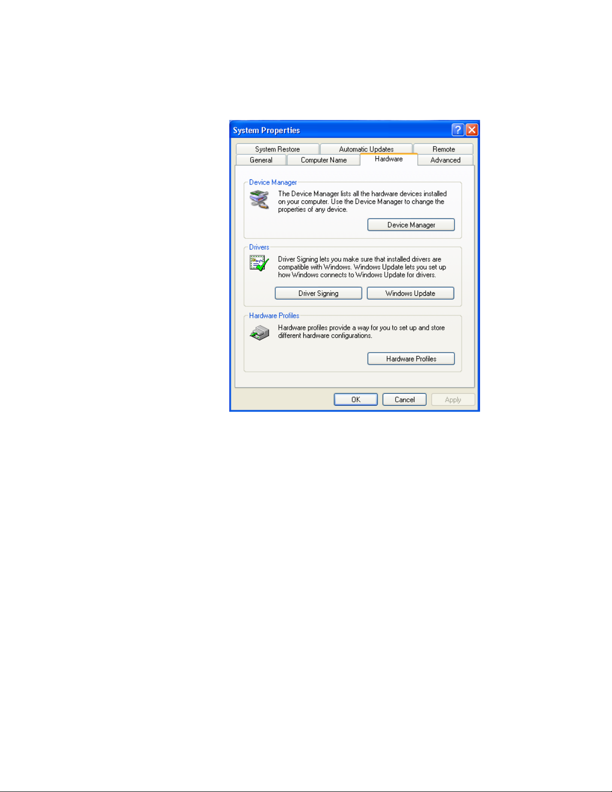
3. Click the Hardware tab.
The Hardware tab is shown in Figure 8.
Figure 8. System Properties Window - Hardware Tab (Microsoft Windows
XP)
4. Click Device Manager.
22
Page 23

AT-WCU201G Wireless Adapter Card Installation Guide
The Device Manager window is shown in Figure 9.
Figure 9. Device Manager Window
5. Expand Network adapters by either double-clicking on it or by clicking
once on the expansion box next to it.
The selection expands to display the network adapter cards installed in
the system. An example is shown in Figure 10.
Figure 10. Expanded Network Adapters Selection
If the Network Adapters selection does not include your new adapter,
be sure that the adapter is securely connected to the USB port on the
computer.
6. Double-click Allied Telesyn AT-WCU201g Wireless USB Adapter.
23
Page 24

Chapter 1: Installing the AT-WCU201G Wireless Adapter Card
The Properties window for the adapter is shown in Figure 11.
Figure 11. AT-WCU201G Wireless Adapter Properties Window
7. Select the Advanced tab. The Advanced tab is shown in Figure 12.
24
Figure 12. Properties Window - Advanced Tab
Page 25

AT-WCU201G Wireless Adapter Card Installation Guide
8. Click Country Region and select your country or regulatory domain
from the Value pull-down menu
9. Click OK.
This completes the procedure for installing the wireless adapter’s
driver on your computer.
25
Page 26

Chapter 1: Installing the AT-WCU201G Wireless Adapter Card
Verifying the Driver Installation
To verify that the driver was correctly incorporated into the Microsoft
Windows operating system, perform the following procedure:
1. Open the Control Panel.
2. Double-click on System.
The System Properties window with the General tab is shown in Figure
7 on page 21.
3. Click the Hardware tab.
The Hardware tab is shown in Figure 8 on page 22.
4. Click Device Manager.
The Device Manager window is shown in Figure 9 on page 23.
5. Expand Network adapters by either double-clicking on it or by clicking
once on the expansion box next to it.
The selection expands to display the network adapter cards installed in
the system. An example is shown in Figure 10 on page 23.
If the Network Adapters selection does not include your new adapter,
be sure that the adapter is securely connected to the USB port on the
computer.
6. Double-click on Allied Telesyn AT-WCU201G Wireless Adapter.
The Properties window of the adapter is shown in Figure 11 on page
24.
7. Verify that the Device Status contains the following: “The device is
working properly.”
26
Page 27

Removing the Adapter Driver
To remove the driver from the computer, perform the following procedure:
1. Connect the AT-WCU201G wireless adapter to the computer. For
instructions, refer to Step 3 in “Installing the Adapter Driver” on
page 17.
Note
The adapter must be connected to the computer in order to remove
the driver.
2. Open the Control Panel.
3. Double-click on System.
The System Properties window is shown in Figure 7 on page 21.
AT-WCU201G Wireless Adapter Card Installation Guide
4. Click the Hardware tab.
The Hardware tab is shown in Figure 8 on page 22.
5. Click Device Manager.
The Device Manager window is shown in Figure 9 on page 23.
6. Expand Network adapters by either double-clicking on it or by clicking
once on the expansion box next to it.
The selection expands to display the network adapter cards installed in
the system. An example is shown in Figure 10 on page 23.
7. Right-click on the wireless adapter driver to be removed and select
either Remove or Uninstall from the pop-up menu, as shown in Figure
13.
Figure 13. Unistall Menu Selection
A confirmation prompt is displayed.
27
Page 28

Chapter 1: Installing the AT-WCU201G Wireless Adapter Card
8. Click OK.
9. Disconnect the wireless adapter from the computer.
This completes the procedure for removing the adapter driver from the
computer.
28
Page 29

Chapter 2
Using the Adapter’s Configuration Utility
This chapter describes the Wireless Configuration utility that comes on the
CD included with your adapter. You can use the utility to configure the
parameter settings on the adapter, such as its IP address and security
settings. The installation and use of this program is optional. If you prefer,
you can configure the adapter settings using Microsoft Windows.
Sections in the chapter include:
“Installing the Configuration Utility” on page 30
“Starting the Configuration Utility” on page 35
“Creating a Preferred WLAN Profile” on page 38
“Configuring the IP Address” on page 45
“Deleting a Preferred WLAN Profile” on page 48
“Importing and Exporting Preferred WLAN Profiles” on page 49
“Working with Profile Groups” on page 52
29
Page 30

Chapter 2: Using the Adapter’s Configuration Utility
Installing the Configuration Utility
To install the configuration program on your computer from the Software
and Documentation CD, perform the following procedure:
1. Power ON the computer.
2. Insert the Software and Documentation CD into the CD drive of the
computer.
Your system should automatically launch the CD and display the main
window, shown in Figure 14. If this window does not appear, doubleclick on the My Computer icon, then double-click on the Allied Telesyn
Installation CD icon.
30
Figure 14. Software and Documentation CD Main Window
3. Click Configuration Utility.
Note
The security prompts in Figure 15, Figure 16, and Figure 17 are from
Microsoft Internet Explorer version 6.0. You may not see these
prompts or you may see different prompts if you are using a different
version of Microsoft Internet Explorer or a different web browser.
Page 31

The prompt in Figure 15 is displayed.
Figure 15. Internet Explorer - Active Content Warning Prompt
4. Click Run.
The prompt in Figure 16 is displayed.
AT-WCU201G Wireless Adapter Card Installation Guide
Figure 16. File Download - Security Warning Prompt
5. Click Run.
The security warning prompt in Figure 17 is displayed.
Figure 17. Internet Explorer - Security Warning Prompt
31
Page 32

Chapter 2: Using the Adapter’s Configuration Utility
6. Click Run.
The Welcome window of the InstallShield Wizard is shown in Figure
18.
Figure 18. InstallShield Wizard — Welcome Window
7. Click Next.
The Choose Destination Location window of the InstallShield Wizard is
shown in Figure 19.
32
Figure 19. InstallShield Wizard — Choose Destination Location Window
Page 33

AT-WCU201G Wireless Adapter Card Installation Guide
8. Select a destination folder on the system for storing the configuration
utility. To select the default directory, click Next. To select a different
directory, click Browse and then select the folder in the Select
Program Folder window.
The InstallShield Wizard displays the Select Program Folder window in
Figure 20.
Figure 20. InstallShield Wizard — Select Program Folder
9. Select the location where you want InstallShield to store an icon for the
configuration utility and click Next. The default is the Allied Telesyn
folder. (InstallShield Wizard creates the folder if it does not already
exist.)
A series of windows appear as the system copies the configuration
utility files from the CD to the specified directory. When all the files are
copied, the Regulatory Domain window in Figure 21 is displayed.
Figure 21. Regulatory Domain Window
33
Page 34

Chapter 2: Using the Adapter’s Configuration Utility
10. Select your country or regulatory domain from the pull-down menu and
click OK.
Caution
The selection of your country or regulatory domain is critical to the
proper operation of the wireless adapter and its adherence to the
laws and regulations that govern the operation of wireless networks
in your country. Failure to select the appropriate country or
regulatory domain can cause the adapter to operate improperly or in
a manner that constitutes a violation of local laws.
The InstallShield Wizard Complete window, shown in Figure 22, is
displayed when the file transfer is finished.
34
Figure 22. InstallShield Wizard Complete Window
11. Remove the Documentation and Software CD from the CD drive.
12. Select Yes, I want to restart my computer now and click Finish.
This completes the procedure for installing the configuration utility on
your computer. To start the program, go to “Starting the Configuration
Utility” on page 35.
Page 35

Starting the Configuration Utility
To start the Wireless Adapter Configuration utility, double-click the
configuration utility icon in the Windows toolbar.
Figure 23. Configuration Utility Icon
Alternatively, select the following from the Start Menu: Start ->
Programs -> Allied Telesyn -> AT-WCU201G Configuration
Wizard.
The program consists of four tabs: Configuration, Status, Option, and
About. The Configuration tab, shown in Figure 24, is displayed by
default when you start the program.
AT-WCU201G Wireless Adapter Card Installation Guide
Figure 24. Configuration Tab
The sections in the Configuration tab are described here:
Available WLANs
This section of the Configuration tab displays information about the
wireless routers and access points of the networks detected by the
wireless adapter. This section will be empty if no wireless networks are
detected.
35
Page 36

Chapter 2: Using the Adapter’s Configuration Utility
The section is useful in reviewing the networks that are currently available
for you to connect to with the adapter, as well as viewing basic information
about the networks. This information includes the following:
ESSID - The name of the network. The name will be blank if the
wireless router or access point is configured not to broadcast it.
MAC (ESSID) - The MAC address of the wireless router or access
point.
Signal - The signal strength from the wireless router or access point.
The range is 0% (low) to 100% (high).
Security - The security mode of the router or access point.
CH - The frequency channel being used by the wireless router or
access point.
Frequency - The operating frequency of the router or access point.
Mode - The radio mode.
This section has the following two buttons:
Refresh - This button updates the Available WLANs section of the tab
with any newly detected wireless routers or access points.
Add - You use this button to create a new Preferred WLAN profile. A
Preferred WLAN profile contains the configuration settings for
connecting to an available wireless network.
Each wireless router or access point in the list is preceded by one of the
icons in Figure 25. The icons indicate the wireless router or access point
to which the wireless adapter is currently connected. The wireless adapter
can be connected to only one router or access point at a time.
Connected Not Connected
Figure 25. Connection Status Icons
Preferred WLANs
This section of the Configuration tab displays a list of the networks the
wireless adapter is configured to access and use. The information
includes the following:
36
ESSID - The name of the network.
Security - The security mode of the network.
Page 37

AT-WCU201G Wireless Adapter Card Installation Guide
In order for the wireless adapter to access one of the networks listed in
Available WANs, you have to configure it with the network’s name and the
appropriate security information. This is referred to as creating a Preferred
WLAN profile. After you have created a profile, the wireless adapter can
connect to the specified network whenever it detects a wireless router or
access point that is a part of the network.
This section contains the following buttons:
New - You use this button to create a new Preferred WLAN profile
when the network is not listed in the Available WLANs section. For
instructions, refer to “Creating a Preferred WLAN Profile” on page 38.
Remove - You use this button to remove a Preferred WLAN profile
from the adapter. Once a network’s corresponding Preferred WLAN
profile is removed, the adapter can no longer access that network. For
instructions on using this button, refer to “Deleting a Preferred WLAN
Profile” on page 48.
Properties - You use this button to view or modify the settings of a
Preferred WLAN profile.
Reconnect - Prompts the adapter to reestablish a connection to a
Preferred WLAN.
Move to - This button moves a Preferred WLAN profile to a different
group. For instructions, refer to “Moving a Preferred WLAN Profile” on
page 53.
Export - This button exports a Preferred WLAN profile into a separate
file for transfer to another computer. For instructions, refer to
“Importing and Exporting Preferred WLAN Profiles” on page 49.
Import - This button imports a Preferred WLAN profile into the
configuration program. For instructions, refer to “Importing and
Exporting Preferred WLAN Profiles” on page 49.
37
Page 38

Chapter 2: Using the Adapter’s Configuration Utility
Creating a Preferred WLAN Profile
The following procedure explains how to create a Preferred WLAN profile
for the following wireless network environments:
No security
WEP security
WPA-PSK and WPA2-PSK security
Note
The AT-WCU201G wireless adapter also supports Ad Hoc, WPA/
WPA2 Enterprise, and 802.1x authentication, but these topics are
beyond the scope of this manual.
To create a Preferred WLAN, perform the following procedure:
1. Start the Wireless Configuration utility, as explained in “Starting the
Configuration Utility” on page 35.
2. If you created groups for storing your Preferred WLAN profiles, click
the name of the group in the Profile Group Control list where you want
to store the new profile. Creating profile groups is optional. For
instructions, refer to “Working with Profile Groups” on page 52.
3. Do one of the following:
If the network that you want to configure as a Preferred Network is
listed in Available WLANs, double-click it or click it once and then
click the Add button. (If you know that the computer is within
reception distance of a wireless router or access point of the
network, but the network is not listed under Available WLANs, try
clicking Refresh.)
If the network is not listed in Available WANs because the wireless
adapter is not in range of the network, click the New button in the
Preferred WLANs section of the tab.
The Wireless Network Properties window is displayed, as shown in
Figure 26 on page 39.
38
Page 39

AT-WCU201G Wireless Adapter Card Installation Guide
The Wireless Network Properties window is shown in Figure 26.
Figure 26. Wireless Network Properties Window
Depending on how you opened the window, some of the information
may already be filled in for you.
4. Go to the appropriate subsection below for instructions on how to
configure the Wireless Network Properties window for your wireless
security system:
“No Security” on page 40
“WEP Security” on page 40
“WPA/WPA2-PSK Security” on page 42
39
Page 40

Chapter 2: Using the Adapter’s Configuration Utility
No Security A Preferred WLAN without security is appropriate in a wireless network
environment where there is no encryption or authentication between the
wireless nodes and the wireless routers or access points.
Caution
A wireless network without security is vulnerable to unauthorized
access.
To configure the Wireless Network Properties window for a Preferred
WLAN with no security, perform the following procedure:
1. Click Wireless Network Name (SSID) and enter the name of the
network. The name is case sensitive.
2. Click Authentication Mode and select Open System from the pulldown menu.
3. Click Data Encryption and select Disable from the pull-down menu.
Note
You must assign the profile an IP address. To set the IP address for
the profile now, go to step 5 in “Configuring the IP Address” on
page 45. To set the IP address ar another time, complete this
procedure.
4. Click OK to close the Wireless Network Properties window.
The Preferred WLANs section of the Configuration tab should now
include a new Preferred WLAN for the network.
5. Click Apply.
This completes the procedure for creating a Preferred WLAN profile
with no security.
WEP Security To configure the Wireless Network Properties window for WEP security,
do the following:
1. Click the Wireless network name (SSID) field and enter the name of
the wireless network. The name is case sensitive.
40
2. Select the Authentication Mode parameter and from the pull-down
menu select either Open System or Shared Key.
In an Open System environment a node does not provide
authentication to the access point in order to access the network. It
only needs to provide the SSID of the network.
Page 41

AT-WCU201G Wireless Adapter Card Installation Guide
In a Shared Key environment a node must authenticate itself to the
access point using a shared WEP key that is present on both the
node and the access point. Only after a node is successful
authenticated will the access point allow it access to the network.
This setting must be the same on both the wireless adapter and the
wireless router or access point.
3. Click the Data Encryption parameter and from the pull-down menu
select WEP. If in step 2 you selected Shared Key, WEP is the only
available option for the Data Encryption parameter.
4. Click the Key Length parameter and select from the pull-down menu
the desired encryption key length and type. Options are:
64 bit hexadecimal or ASCII key (40 bit encryption key and 24 bit
initialization vector)
128 bit hexadecimal or ASCII (104 bit encryption key and 24 bit
initialization vector)
152 bit hexadecimal or ASCII (128 bit encryption key and 24 bit
initialization vector)
This setting must be the same on the wireless client and the access
point.
5. Enter the WEP encryption keys. You can enter from one to four keys.
The wireless client uses the encryption keys to decode the network
traffic that it receives from the access point as well as to encrypt the
network traffic that it sends to the access point. If in Step 6 you
selected Share Key, the client also uses a key when authenticating
itself to the access point.
When entering the WEP keys, note the following rules:
The order of the keys here must match the order of the keys on the
wireless router or access point.
Valid ASCII characters are a - z, A - Z, and 0 - 9. Valid hexadecimal
characters are 1 - 9 and A - F. (A WEP key of ASCII characters is
case sensitive.)
The key lengths for a hexadecimal key are as follows:
– A key length of 64 bits requires 10 hexadecimal
characters.
– A key length of 128 bits requires 26 hexadecimal
characters.
– A key length of 152 bits requires 32 hexadecimal
characters.
41
Page 42

Chapter 2: Using the Adapter’s Configuration Utility
The key lengths for an ASCII key are as follows:
The wireless client and access point can use different keys to
6. Select Default Key and from the pull-down menu select the key that
the wireless adapter should use to encryption its outgoing traffic. If in
Step 5 you selected Share Key, the default key is also used by the
client when authenticating itself to the access point.
Note
You must assign the profile an IP address. To set the IP address for
the profile now, go to step 5 in “Configuring the IP Address” on
page 45. To set the IP address at another time, complete this
procedure.
– A key length of 64 bits requires 5 ASCII characters.
– A key length of 128 bits requires 13 ASCII
characters.
– A key length of 152 bits requires 16 ASCII
characters.
encode the network traffic that they each send. However, both keys
must be entered on both devices and the keys must occupy the
same positions in the encryption key tables (Key 1, Key 2, etc.) on
the devices.
WPA/WPA2PSK Security
7. Click OK to close the Wireless Network Properties window.
The Preferred WLANs section of the Configuration tab should now
include a new Preferred WLAN for the network.
8. In the main window of the configuration utility, click Apply.
This completes the procedure for creating a Preferred WLAN profile
with WEP security.
To configure the Wireless Network Properties window for Wi-Fi Protected
Access (WPA) Preshared Key (PSK) or WPA2-PSK security, do the
following:
1. Click the Wireless network name (SSID) field and enter the name of
the network. The name is case sensitive.
2. Click Authentication Mode and select either WPA-PSK or WPA2-
PSK from the pull-down menu.
Note
Do not select WPS2-PSK unless the wireless access point features
WPA2.
42
Page 43

AT-WCU201G Wireless Adapter Card Installation Guide
3. Click Data Encryption and select either TKIP (Temporal Key Integrity
Protocol) or AES (Advanced Encryption Standard) from the pull-down
menu. The encryption method must be the same on both the wireless
node and the wireless access point.
4. Click the Authentication Config button.
The Advance Security Settings window is shown in Figure 27.
Figure 27. Advance Security Settings Window
5. Click the WPA Passphrase field and enter the passphrase (also
referred to as the shared secret) from the wireless router or access
point.
6. Click OK to close the Advance Security Settings window.
Note
You must assign the profile an IP address. To set the IP address
now, go to step 5 in “Configuring the IP Address” on page 45. To set
the IP address at another time, complete this procedure.
43
Page 44

Chapter 2: Using the Adapter’s Configuration Utility
7. Click OK to close the Wireless Network Properties window.
The Preferred WLANs section of the Configuration tab should now
include a new Preferred WLAN profile for a wireless network using
WPA-PSK or WPA2-PSK security.
8. In the main window of the configuration utility, click Apply.
This completes the procedure for creating a Preferred WLAN profile
with WPA/WPA-PSK security.
44
Page 45

Configuring the IP Address
To configure the IP address for a Preferred WLAN profile or to activate the
DHCP client, perform the following procedure:
1. Start the configuration program by clicking the program’s icon, shown
in Figure 23 on page 35, located in the toolbar on the desktop.
The main window of the configuration utility is shown in Figure 24 on
page 35.
Note
Perform step 2 if you created profile groups, which are optional. For
further information, refer to “Working with Profile Groups” on
page 52
2. In the Profile Group Control section of the Configuration tab, click the
group containing the profile whose IP address you want to assign or
modify.
AT-WCU201G Wireless Adapter Card Installation Guide
3. In the Preferred WLANs section of the window, click the Preferred
WLAN profile whose IP address you want to assign or change.
4. Click Properties.
5. The Wireless Network Properties window, containing the parameter
settings of the selected WLAN profile, is displayed. An example of the
window is shown in Figure 26 on page 39.
6. Click IP & Proxy Setting.
45
Page 46

Chapter 2: Using the Adapter’s Configuration Utility
The LAN Settings window is shown in Figure 28.
Figure 28. LAN Settings Window
7. If you want the adapter to obtain its IP address, subnet mask, and
default gateway from a DHCP server on your network, click Obtain an
IP address automatically. A check in the dialog box activates the
DHCP client.
8. If you want to manually enter an IP address, do the following:
a. Click Obtain an IP address automatically to remove the check
from the dialog box.
b. In the IP address field, enter an IP address for the adapter.
c. In the Subnet mask field, enter the adapter’s subnet mask.
d. If the wireless node needs to communicate through a router, enter
the IP address of the router in the Default gateway field.
9. If your network has a domain name service, which converts domain
names into IP addresses, and you want the computer to obtain the IP
address of the domain name server from a DHCP or BOOTP server,
select Obtain DNS server address automatically. To enter the IP
address of a domain name server manually, select Use the following
46
Page 47

AT-WCU201G Wireless Adapter Card Installation Guide
DNS server addresses and enter the IP address in the field. You can
enter up to two IP addresses of domain name servers. The alternate
DNS server address is used only if the server specified as the
preferred DNS server does not respond.
10. Click OK to close the LAN Settings window.
11. Click OK to close the Wireless Network Properties window.
12. Click the Option tab.
13. Verify that the option Enable IP Setting and Proxy Setting in Profile
has a check mark. If it does not, click it once to add a check mark. If
you do not activate this option, the IP address for the wireless adapter
must be set using Windows, as explained in “Setting the IP Address”
on page 58.
14. Click the Configuration tab.
15. In the Configuration tab, click Apply.
Note
The actual initial assignment of an IP address to a wireless adapter
using the configuration program can take up to a minute to occur.
16. If you are finished using the configuration utility, click OK.
47
Page 48

Chapter 2: Using the Adapter’s Configuration Utility
Deleting a Preferred WLAN Profile
To delete a Preferred WLAN profile, perform the following procedure:
1. Start the configuration program by clicking the program’s icon, shown
in Figure 23 on page 35, located in the toolbar on the desktop.
The main window of the configuration utility is shown in Figure 24 on
page 35.
Note
Perform step 2 if you created profile groups, which are optional. For
further information, refer to “Working with Profile Groups” on
page 52
2. In the Profile Group Control section of the Configuration tab, click the
group containing the profile to be deleted.
3. In the Preferred WLANs section of the Configuration tab, click the
Preferred WLAN you want to delete.
4. Click Remove.
The selected Preferred WLAN is deleted from the Wireless Adapter
Configuration Utility.
5. Click Apply.
6. If you are finished using the configuration utility, click OK.
48
Page 49

AT-WCU201G Wireless Adapter Card Installation Guide
Importing and Exporting Preferred WLAN Profiles
You can export a Preferred WLAN profile into a separate file and then
import the file onto another computer. This can simplify the task of
configuring a large number of AT-WCU201G adapters that are to have
similar or identical Preferred WLAN profiles.
Exporting a
Preferred WLAN
Profile
To export a Preferred WLAN profile into a separate file for transfer to
another system, perform the following procedure:
1. Start the configuration program by clicking the program’s icon, shown
in Figure 23 on page 35, located in the toolbar on the desktop.
The main window of the configuration utility is shown in Figure 24 on
page 35.
Note
Perform step 2 if you created profile groups, which are optional. For
further information, refer to “Working with Profile Groups” on
page 52
2. In the Profile Group Control section of the Configuration tab, click the
name of the group containing the profile to be exported.
3. In the Preferred WLAN section of the Configuration tab, click the profile
to export.
4. Click Export.
The Profile Password window is shown in Figure 29.
Figure 29. Profile Password
5. In the Input Profile Password and Confirm Again fields, enter a
password for the profile. The password protects the exported profile
from unauthorized use. The password can be from 1 to 16
alphanumeric characters. The password is case sensitive. Spaces are
allowed. You are prompted for this password when you import the
profile onto another computer.
6. Click OK.
49
Page 50

Chapter 2: Using the Adapter’s Configuration Utility
The Save As window is displayed for saving the profile file.
7. Specify the location where you want to store the profile and a filename.
The filename extension must be “.AWP”.
8. Click OK.
The profile is saved as a separate file on your computer.
This completes the procedure for exporting a Preferred WLAN profile.
By saving the profile onto a floppy disk or CD, you can transfer the disk
to another computer that has an AT-WCU201G adapter and the
configuration utility, and import the profile onto that system, as
explained in the next procedure.
Importing a
Preferred WLAN
Profile
To import a Preferred WLAN profile into the configuration utility, perform
the following procedure:
1. Start the configuration program by clicking the program’s icon, shown
in Figure 23 on page 35, located in the toolbar on the desktop.
The main window of the configuration utility is shown in Figure 24 on
page 35.
Note
Perform step 2 if you created profile groups, which are optional. For
further information, refer to “Working with Profile Groups” on
page 52
2. In the Profile Group Control section of the Configuration tab, click the
name of the group where you want to import the profile.
3. Click Import.
4. In the Open window, specify the filename and location of the profile to
import and click OK.
50
The Profile Password window is shown in Figure 30.
Figure 30. Profile Password Window
5. Enter the profile’s password and click OK. The password is case
sensitive.
Page 51

AT-WCU201G Wireless Adapter Card Installation Guide
The profile is incorporated as a Preferred WLAN into the configuration
utility. The wireless adapter will establish a connection if it is within
range of a wireless router or access point of the network defined by the
profile.
51
Page 52

Chapter 2: Using the Adapter’s Configuration Utility
Working with Profile Groups
Profile groups allow you to organize your Preferred WLAN profiles. You
can place the profiles in different groups to make them easier to find and
manage. Creating profile groups is optional.
There can be only one active profile group at a time. The wireless adapter
uses the profiles in the active group to establish a connection to a wireless
network. The profiles in the other groups are inactive. You can work on all
the profiles in all the groups, not just the active group, but only the profiles
in the active group are used to make a wireless connection. For
instructions on how to designate the active group, refer to “Selecting the
Active Profile Group” on page 55.
Creating a Profile
Group
To create a new profile group, perform the following procedure:
1. Start the configuration program by clicking the program’s icon, shown
in Figure 23 on page 35, located in the toolbar on the desktop.
The main window of the configuration utility is shown in Figure 24 on
page 35.
2. In the Profile Group Control section of the Configuration tab, click the
empty field to the left of the New button and enter a name for the new
profile group. The name can be up to 15 alphanumeric characters.
Spaces are allowed.
3. Click New.
The new group is added to the list in the Profile Group Control section.
If this is the first profile group, note the following:
All of the existing profiles in the Preferred WLAN section are
automatically added to the group.
The group is automatically marked as the active group, designated
with the icon in Figure 31. The computer uses the profiles in the
active group to connect to a wireless network. There can only be
one active group at a time. To change the active group, refer to
“Selecting the Active Profile Group” on page 55.
52
Figure 31. Active Group Icon
4. Click the name of the new group to select the group.
Page 53

AT-WCU201G Wireless Adapter Card Installation Guide
5. You can now add profiles to the new group by either creating them or,
if they already exist, moving them from an existing group to the new
group. For directions, refer to “Creating a Preferred WLAN Profile” on
page 38 and “Moving a Preferred WLAN Profile” on page 53.
Moving a
Preferred WLAN
Profile
To move a profile to a different group, perform the following procedure:
1. Start the configuration program by clicking the program’s icon, shown
in Figure 23 on page 35, located in the toolbar on the desktop.
The main window of the configuration utility is shown in Figure 24 on
page 35.
2. In the Profile Group Control section of the Configuration tab, click the
group that contains the profile to be moved.
The profiles of the group appear in the Preferred WLANs section.
3. In the Preferred WLAN section, click the profile to be moved to a
different group and click Move to.
A list of the existing profile groups is displayed. An example is shown
Figure 32.
Renaming a
Group
Figure 32. Move to Another Group Window
4. Click the new group for the profile and click OK.
The profile is moved to the designated group.
To rename a profile group, perform the following procedure:
1. Start the configuration program by clicking the program’s icon, shown
in Figure 23 on page 35, located in the toolbar on the desktop.
The main window of the configuration utility is shown in Figure 24 on
page 35.
2. In the Profile Group Control section of the Configuration tab, click the
name of the group to be renamed. You can rename only one group at
a time.
53
Page 54

Chapter 2: Using the Adapter’s Configuration Utility
3. Click Rename.
The Group Rename window is shown in Figure 33.
Figure 33. Group Rename Window
4. Enter the new name for the group and click OK. The name can be up
to 15 alphanumeric characters. Spaces are allowed.
Deleting a Group This procedure explains how to delete a profile group.
Caution
Deleting a profile group deletes all the Preferred WLAN profiles in
the group. If you want to retain the profiles, move them to a different
group as explained in “Moving a Preferred WLAN Profile” on
page 53, or, alternatively, export the profiles into separate files, as
explained in “Exporting a Preferred WLAN Profile” on page 49.
To delete a profile group, perform the following procedure:
1. Start the configuration program by clicking the program’s icon, shown
in Figure 23 on page 35, located in the toolbar on the desktop.
The main window of the configuration utility is shown in Figure 24 on
page 35.
2. In the Profile Group Control section of the Configuration tab, click the
group to be deleted. You can delete only one group at a time.
3. Click Delete.
A confirmation prompt is displayed.
4. Click Yes to delete the group or No to cancel the procedure.
If you select Yes, the group and its profiles are deleted from the
computer.
54
Page 55

AT-WCU201G Wireless Adapter Card Installation Guide
Selecting the
Active Profile
Group
This procedure selects the active profile group for an adapter. The switch
uses the profiles in the active group to establish a connection to a wireless
network. There can be only one active group at a time for a wireless
adapter. The active group is designated with the icon in Figure 31 on page
52.
To select the active profile group, perform the following procedure:
1. Start the configuration program by clicking the program’s icon, shown
in Figure 23 on page 35, located in the toolbar on the desktop.
The main window of the configuration utility is shown in Figure 24 on
page 35.
2. In the Profile Group Control section of the Configuration tab, click the
group to be designated as the active group and click Select.
Alternatively, double-click the group. The selected group is designated
with the symbol in Figure 31 on page 52.
The profiles stored in the selected group are now active. The wireless
adapter will attempt to establish a connection to a wireless network
using the profiles in the active group.
55
Page 56

Chapter 2: Using the Adapter’s Configuration Utility
56
Page 57

Chapter 3
Microsoft Windows XP
This chapter contains the procedures for configuring the wireless adapter
on a Microsoft Windows XP system. Sections in the chapter include:
“Setting the IP Address” on page 58
“Quick Configuration” on page 62
“Manually Configuring the Wireless Adapter” on page 65
Note
The wireless adapter is supported on Microsoft Windows 2000, but
this guide does not contain instructions for configuring the adapter
on that operating system.
57
Page 58

Chapter 3: Microsoft Windows XP
Setting the IP Address
To set the IP address of the adapter or to activate the DHCP client,
perform the following procedure:
1. Open the Control Panel.
2. Double-click on Network Connections.
An example of the Network Connections window is shown in Figure
34.
Figure 34. Network Connections Window
3. Right-click on the Wireless Network Connection icon of the wireless
adapter and select Properties from the pull-down menu, as shown in
Figure 35.
Figure 35. Wireless Network Connection Pull-down Menu
58
Page 59

AT-WCU201G Wireless Adapter Card Installation Guide
The Wireless Network Connections Properties window is shown in
Figure 36.
Figure 36. Wireless Network Connection Properties Window
4. Select Internet Protocol (TCP/IP), then click Properties.
59
Page 60

Chapter 3: Microsoft Windows XP
The Internet Protocol (TCP/IP) Properties window is shown in Figure
37.
Figure 37. Internet Protocol (TCP/IP) Properties Window
5. If you want the adapter to obtain its IP address, subnet mask, and
default gateway from a DHCP server on your network, select Obtain
an IP address automatically. If you want to set these parameters
manually, select Use the following IP address and enter the
information into the fields.
6. If your network has a domain name service, which converts domain
names into IP addresses, and you want the computer to obtain the IP
address of the domain name server from a DHCP server, select
Obtain DNS server address automatically. To enter the IP address
of a domain name server manually, select Use the following DNS
server addresses and enter the IP address in the field. You can enter
up to two IP addresses of domain name servers. The alternate DNS
server address is used only if the server specified as the preferred
DNS server does not respond.
7. Click OK to close the Internet Protocol (TCP/IP) Properties window.
8. Click OK to close the Wireless Network Connection Properties
window.
This completes the procedure for configuring the IP address and
subnet mask of the wireless adapter card.
60
Page 61

AT-WCU201G Wireless Adapter Card Installation Guide
You are now ready to configure the adapter’s security system using the
Wireless Adapter Configuration program.
61
Page 62

Chapter 3: Microsoft Windows XP
Quick Configuration
This procedure explains how to quickly configure the wireless adapter
using Microsoft Windows XP. Note the following before performing this
procedure:
You must be within reception range of a wireless router or access point
The wireless router or access point must be broadcasting its SSID.
If the wireless router or access point is running WEP security, the
To perform a quick configuration of the wireless adapter, perform the
following procedure:
1. Power on the computer and attach the wireless adapter.
of the network.
network authentication setting must be Open system or both Open and
Shared systems. The quick configuration procedure will not work if
WEP security is set to Shared system only.
The computer will detect the wireless network and display a prompt
above the wireless connection icon in the tool bar on the desktop, as
shown in Figure 38.
Figure 38. Wireless Icon
2. Click the wireless icon in the toolbar.
62
Page 63

AT-WCU201G Wireless Adapter Card Installation Guide
Windows displays the SSIDs of the detected wireless networks in the
Wireless Network Connection window. An example of the window is
shown in Figure 39.
Figure 39. Wireless Network Connection Window
3. Double-click on the wireless network to connect to or, alternatively,
click once on the network and click Connect.
If the wireless router or access point is running WEP, WPA, or WPA2,
the Wireless Network Connection window, shown in Figure 40,
prompts you for the WEP encryption key or, in the case of WPA or
WPA2, the passphrase, also referred to as the shared secret. Go to
Step 5 to enter the encryption key or passphrase.
Figure 40. Wireless Network Connection Prompt (WEP or WPA Security)
63
Page 64

Chapter 3: Microsoft Windows XP
If there is no security on the wireless network, the Wireless Network
Connections window in Figure 41 is displayed.
Figure 41. Wireless Network Connection - No Security
4. Click Connect Anyway.
At this point, the wireless adapter establishes a connection with the
wireless router or access point.
5. For WEP, WPA, or WPA2 security, in the Network Key and Confirm
Network Key fields enter the router or access point’s encryption key in
the case of WEP security or passphrase for WPA and WPA2 security.
After entering the key, the wireless adapter connects to the selected
network.
64
Page 65

Manually Configuring the Wireless Adapter
The following procedure explains how to configure the wireless adapter for
the following wireless network environments:
No security
WEP security
WPA-PSK and WPA2-PSK security
Note
The AT-WCU201G wireless adapter also supports Ad Hoc, WPA/
WPA2 (Enterprise), and 802.1x authentication, but these topics are
beyond the scope of this manual.
To manually configure the wireless adapter’s security settings, perform the
following procedure:
AT-WCU201G Wireless Adapter Card Installation Guide
1. Connect the wireless adapter to the computer.
2. Open the Control Panel.
3. Double-click on Network Connections.
An example of the Network Connections window is shown in Figure 34
on page 58.
4. Right-click on the Wireless Network Connection icon of the wireless
adapter and select Properties from the pull-down menu, as shown in
Figure 35 on page 58.
The Wireless Network Connections Properties window is shown in
Figure 36 on page 59.
5. Select the Wireless tab.
65
Page 66

Chapter 3: Microsoft Windows XP
The Wireless tab is shown in Figure 42.
Figure 42. Wireless Tab
6. Click Add. The Wireless Network Properties window is shown in
Figure 43.
66
Figure 43. Wireless Network Properties Window
Page 67

AT-WCU201G Wireless Adapter Card Installation Guide
7. Go to the appropriate subsection below for instructions on how to
configure the Wireless Network Properties window for your wireless
security system:
“No Security” on page 67
“WEP Security” on page 67
“WPA/WPA2-PSK Security” on page 68
No Security To configure the Wireless Network Properties window for a wireless
network that has no security, do the following:
1. Click the Network Name (SSID) field and enter the SSID of the
wireless network. The network name is case sensitive.
2. Click the Network Authentication parameter and select Open
System from the pull-down menu.
3. Click the Data Encryption parameter and select Disabled from the
pull-down menu.
4. Click OK.
WEP Security To configure the Wireless Network Properties window for WEP security,
do the following:
1. Click the Network Name (SSID) field and enter the SSID of the
wireless network. The network name is case sensitive.
2. Click the Network Authentication parameter and from the pull-down
menu select either Open System or Shared Key.
A node in an Open System environment is not authenticated by the
access point. The node need only provide the SSID of the network.
A node in a Shared Key environment is authenticated by the
access point using a shared WEP key that is present on both the
node and the access point. Only after a node is successful
authenticated does the access point allow it access to the network.
3. Click the Data Encryption parameter and from the pull-down menu
select WEP.
4. If the encryption key will not be provided automatically to the wireless
adapter, click The key is provided for me automatically to deselect
the option and perform steps 5 and 6. If the encryption key will be
provided automatically to the adapter, leave the option enabled and go
to step 7.
5. In the Network Key and Confirm Network Key fields, enter the
encryption key from the wireless router or access point.
67
Page 68

Chapter 3: Microsoft Windows XP
6. Click Key Index and specify the position of the encryption key in the
encryption key table on the wireless router or access point. The range
is 1 to 4.
7. Click OK.
WPA/WPA2PSK Security
To configure the Wireless Network Properties window for WPA-PSK or
WPA2-PSK security, do the following:
1. Click the Network Name (SSID) field, enter the SSID of the wireless
network. The network name is case sensitive.
2. Click the Network Authentication parameter and from the pull-down
menu select either WPA-PSK or WPA2-PSK.
Note
Do not select WPA2-PSK unless the wireless router or access point
supports WPA2.
3. Click the Data Encryption parameter and from the pull-down menu
select either TKIP or AES.
4. In the Network Key and Confirm Network Key fields, enter the router
or access point’s passphrase (also referred to as the shared secret).
5. Click OK.
68
Page 69

Appendix A
Technical Specifications
This appendix lists the technical specifications of the AT-WCU201G
wireless adapter.
General
Compliance Standard IEEE 802.11, IEEE 802.11b, IEEE 802.11g
Bus Interface Universal Serial Bus (USB) 2.0
Antenna Type Integrated antenna
IEEE 802.11b Operation
Standard IEEE 802.1b
Radio and Modulation
Schemes
Operating Frequency 2400 ~ 2497 MHz ISM band
Channel Numbers 11 channels for United States
Data Rates 1, 2, 5.5, and 11 Mbps
Media Access Protocol CSMA/CA with ACK
Transmitter Output
Power
Receiver Sensitivity Typical -82 dBm for 11 Mbps @ 8% Packet
DQPSK, DBPSK, DSSS, and CCK
13 channels for European countries
Typical 16 dBm at 1, 2, 5.5, and 11 Mbps
Error Rate (PER)
Typical -87 dBm for 2 Mbps @ 8% PER
IEEE 802.1g Operation
Standard 2.4 GHz OFDM (IEEE 802.11g)
Radio and Modulation
Schemes
BPSK, QPSK, 16QAM, 64QAM, and OFDM
Operating Frequency
2400 ~ 2497 MHz ISM band
69
Page 70

Appendix A: Technical Specifications
Channel Numbers 11 channels for United States
13 channels for European countries
Data Rates
Media Access Protocol CSMA/CA with ACK
Transmitter Output
Power
6, 9, 12, 18, 24, 36, 48, 54 Mbps
Typical RF output power at each data rate
+15 dBm at 48 and 54 Mbps
+16 dBm at 36 Mbps
+17 dBm at 6, 9, 12, 18, and 24 Mbps
Receiver Sensitivity
Typical sensitivity at which frame (1000-byte
PDUs) error rate equals 10%:
-88 dBm at 6 Mbps
-86 dBm at 9 Mbps
-84 dBm at 12 Mbps
-82 dBm at 18 Mbps
-78 dBm at 24 Mbps
-74 dBm at 36 Mbps
-69 dBm at 48 Mbps
-66 dBm at 54 Mbps
Physical Specifications
Dimensions 25 (W) x 12 (D) x 81 (H) mm
Weight 40.3 g (main unit)
Physical and Environmental
Operating Temperature
Storage Temperature
Power Requirements
Operating Voltage 5VDC +/-5%
Current Consumption 472 mA at continuous transmit mode
0° C to 40° C (32° F to 104° F) Humidity: <90%
(non-condensing)
-25° C to 70° C (-13° F to 158° F) Humidity:
<95% (non-condensing)
290 mA at continuous receive mode
70
Page 71

Appendix B
Regulatory Domains
This appendix lists the IEEE 802.11g channels supported by the world’s
regulatory domains.
Regulatory Domains
Channel
Identifier
12412
22417
32422
42427
52432
62437
72442
82447
92452
Frequency
(MHz)
United
States
(FCC)
XX
XX
XX
XX
XX
XX
XX
XX
XX
Mexico
Germany,
Italy, United
Kingdom
(ETSI)
France
10 2457
11 2462
12 2467
13 2472
14 2484
XX X X
XX X X
XX
XX
71
Page 72

Appendix B: Regulatory Domains
72
 Loading...