

Page 1

CentreCOM AT-FS708
CentreCOM AT-FS708E
Fast Ethernet Switches
Installation Guide
PN 613-10864-00 Rev A
Page 2

Copyright 2000 Allied Telesyn International, Corp.
960 Stewart Drive Suite B, Sun nyva le CA 94086, USA
All rights reserved. No part of this publication may be reproduced without prior written
permission from Allied Telesyn International, Corp.
Ethernet is a registered trademark of Xerox Corporation. All other product names,
company names, logos or o ther designa t ions me n tioned herein are trademarks or
registered trademarks of their respective owners.
Allied Telesyn International, Corp. reserves the right to make changes in specifications
and other information containe d in this document without prior written notice. The
information provided herein is subject to change without notice. In no event shall Allie
Telesyn International, Corp. be liable for any incide ntal, special, indirect, or
consequential damages whatsoever, including but not limited to lost profits, arising out
of or related to this manual or the information contained herein, even if Allied Telesyn
International, Corp. has been advised of, known, or should have known, the possibility
of such damages.
Page 3

Electrical Safety and Emission Compliance Statements
Standards: This product meets the following stand ar ds.
U.S. Federal C ommunications Commis s i on
DECLARATION OF CONFORMITY
Manufacture Name: Allied Telesyn International
Manufacture Address: 960 Stewart Drive, Suite B
Manufacture Telephone: 408-730-0950
Declares that the product: Unmanaged, Fast Etherne t S w itches
Model Number: AT-FS708 and AT-FS708
This product complies with FCC Part 15B, Class B Limits:
This device complies with part 15 of the FCC Rules. Operation is subject to
the following two conditions: (1) This device must not cause harmful
interference, and (2) this device must accept any interference received,
including interference that may cause undesired operation.
RADIATED ENERGY
Note: This equipment has been tested and found to comply with the limits
for a Class B digital device pursuant to Part 15 of FCC Rules. These limits
are designed to provide reasonable protection against harmful interference
in a residential installation. This equipment generates, uses and can radiate
radio frequency energy and, if not installed and used in accordance with
instructions, may cause harmful interference to radio or television
reception, which can be determined by turning the equipment off and on.
The user is encouraged to try to correct the interference by one or more of
the following measures:
- Reorient or relocate the receiving antenna.
- Increase the separation between the equipment and the receiver.
- Connect the equipment into an outlet on a circuit different from that to
which the receiver is connected.
- Consult the dealer or an experienced radio/TV technician for help.
Changes and modifications not expressly approved by the manufacturer or
registrant of this equipment can void your auth o ri ty t o operate this
equipment under Federal Communications Commission rules.
Sunnyvale, CA 94086 USA
E
Industry Canada
This Class B digital apparatus meets all requirements of the Canadian
Interference-Causing Equipment Regulations.
Cet appareil numérique de la classe B respecte toutes les exigences du
Règlement sur le matériel brouilleur du Canada.
iii
Page 4

Electrical Safety and Emission Compliance Statements
RFI Emission EN55022 Class B
!
1
Immunity EN50082Electrical Safety EN60950, UL 1950, CSA 950
Important: Ap pendix B contains translated safety statements for installing
this equipment. When you see the
safety statement in your language.
Wichtig: Anhang B enthält übersetzte Sicherheitshinweise für die Installation
dieses Geräts. Wenn Sie
Sicherheitshinweis in Ihrer Sprache nach.
Vigtigt: Tillæg B indeholder oversatte sikkerhedsadvarsler, der vedrører
installation af dette udstyr. Når De ser symbolet
og finde de oversatte sikkerhedsa dva rsl er i Deres eget sprog.
Belangrijk: Appendix B bevat vertaalde veiligheidsopmerkingen voor het
installeren van deze apparatuur. Wanneer u de
voor vertaalde veiligheidsinstructies in uw taal.
Important : L'annexe B contient les instructions de sécurité relatives à
l'installation de cet équipement. Lorsque vous voyez le symbole
vous à l'annexe B pour consulter la traduction de ces instructions dans votre
langue.
Tärkeää: Liite B sisältää tämän laitteen asentamiseen liittyvät käännetyt
turvaohjeet. Kun näet
B.
Importante: l’Appendice B contiene avvisi di sicurezza tradotti per
l’installazione di questa apparecchiatura. Il simbolo
l’Appendice B per l’avviso di sicurezza nella propria lingua.
!
sehen, schlagen Sie in Anhang B den übersetzten
!
-symbolin, katso kään nettyä tu rva ohjetta liitteestä
1
! 2
!
3
!
, go to Appendix B for the translated
!
, skal De slå op i tillæg B
!
ziet, raadpleeg Appendix B
!
!
, indica di consultare
, reportez-
Viktig: Tillegg B inneholder oversatt sikkerhetsinformasjon for installering
av dette utstyret. Når du ser
oversatte sikkerhetsinf or masjo nen på ønsket språk.
Importante: O Anexo B contém advertências de segurança traduzidas para
instalar este equipamento. Quando vir o símbolo
segurança traduzida no seu idioma no Anexo B.
Importante: El Apéndice B contiene mensajes de seguridad traducidos para
la instalación de este equipo. Cuando vea el símbolo
para ver el mensaje de seguridad traducido a su idioma.
Obs! Bilaga B innehåller översatta säkerhetsmeddelanden avseende
installationen av denna utrustning. När du ser
att läsa det översatta säkerhetsmeddelandet på ditt språk.
iv
!
, åpner du til Tillegg B for å finne den
!
, leia a advertência de
!
, vaya al Apéndice B
!
, skall du gå till Bilaga B för
Page 5

Table of Contents
Electrical Safety and Emission Compliance Statements
Welcome to Allied Telesyn
Where to Find Web-based Guides ................................................................... vii
Documentation Conventions............................................................................vii
Contacting Allied Teleysn...............................................................................viii
Online Support............ .................. ...........................................................viii
For Technical Support and Services................ ........................................viii
Technical Support E-mail Addresses......................................................viii
Returning Products ........................................................................................... ix
FTP Server.................. .............. ......................................................................... ix
For Sales or Corporate Information .................................................................. x
Tell Us What You Think .................. .. .. .............................................................. x
Chapter 1
Product Description
Overview ............................................................................................................. 1
Common Major Features.................................................................................... 2
Physical Description........................................................................................... 3
Connectors................................................................................................... 3
Front Panel LEDs........................................................................................ 3
MDI Port...................................................................................................... 4
Power Supply............................................................................................... 5
Required Voltage......................................................................................... 5
Auto-Negotiation ................................................................................................ 5
......................................................................... vii
...................................................................................... 1
....................iii
Chapter 2
Installation
Before You Proceed........................ ..................................................................... 7
Verifying Package Contents.................. ............................................................. 7
Site Requirements. .. .. ......................................................................................... 8
Desktop Installation........................................................................................... 8
Wall-Mount Installation..................................................................................... 9
Rack-Mount Installation (AT-FS708 only) . ..................................................... 10
Configuration.................................................................................................... 11
Standalone Configuration......................................................................... 11
Cascade Configuration.............................................................................. 12
Uplink Configuration...... .. .................. ...................................................... 13
...................................................................................................... 7
v
Page 6

Chapter 3
Troubleshooting
...........................................................................................15
Connectivity Testing.........................................................................................15
Problem Solving................................................................................................16
Is the Unit Receiving Power?....................................................................16
Is the Link/Activity LED Lit?................................................................... 16
Appendix A
Switch Specifications
..................................................................................19
Physical Characteristics........................ ...........................................................19
Standards.......................................................................................................... 19
Cabling Specifications......................................................................................20
Electrical Specifications...................................................................................20
UTP (RJ-45) Connector ....................................................................................20
Low Last Bit-to-First Delay.............. ...............................................................20
Network Specifications.....................................................................................21
100Base-TX Cable............................................................................................. 21
100Base-TX Connector Pinouts.......................................................................22
Straight-through Cable...... .. .. .................. .................................................22
Crossover Cable......................................................................................... 22
Appendix B
Translated Safety and Emission Information
.......................................23
Appendix C
Technical Support Fax Order
...................................................................37
Incident Summary............................................................................................37
Appendix D
AT-FS708 and AT-FS708E Switches Installation Feedback
vi
...............39
Page 7
Welcome to Allied Telesyn
This guide contains instructions on how to instal l and configure the A T-FS708
and AT-FS708E Ethernet Switches.
Where to Find Web-based Guides
The Allied Telesyn web site at
easy way to access the most recent documentation and technical information
for all of our products. For product guides, you can go directly to the following
web page:
www.alliedtelesyn.com/support/lib_allproducts.htm
www.alliedtelesyn.com
provides you with an
.
Documentation Conventions
Throughout this guide, you will notice several conventions that you should
become familiar with fi rst bef ore installing the product.
Note
A note provides a d ditional informati on.
Caution
A caution indicates that performing or omitting a specific action may
result in equipm ent damage or loss of data.
Warning
A warning indicates that performing or omitting a specific action may
result in bodily injury.
vii
Page 8

Welcome to Allied Telesyn
Contacting Allied Teleysn
There are several ways to contact Allied Telesyn technical support, online,
telephone, fax or by e-mail.
Online Support
You can request technical support online by filling out the Tech-Assistant
Form at
For Technical Support and Services
www.alliedtelesyn.com/forms/feedtech.htm
.
Americas
United States, Canada, Mexico,
Central America, South America
Tel: 1 (800) 428-4835, option 4
Fax: 1 (503) 639-317
Asia
Singapore, Taiwan, Th ailan d, Malaysia,
Indonesia, Korea, Philippines, China,
India, Hong Kong
Tel: (+65) 381-5612
Fax: (+65) 383-3830
Australia
Tel: 1 (800) 000-880
Fax: (+61) 2-9438-4966
France
France, Belgium, Luxembourg,
The Netherlands, Middle East, Africa
Tel: (+33) 0-1-60-92-15-25
Fax: (+33) 0-1-69-28-37-49
6
Technical Support E-mail Addresses
United States and Canada
TS1@alliedtelesyn.com
Germany
Germany, Switzerland, Austria, E astern
Europe
Tel: (+49) 0130/83-56-66
Fax: (+49) 30-435-900-115
Italy
Italy, Spain, Portugal, Greece, Turkey,
Israe
l
Tel: (+39) 02-416047
Fax: (+39) 02-419282
Japan
Tel: (+81) 3-3443-5640
Fax: (+81) 3-3443-2443
United Kingdom
United Kingdom, Denmark, Norway,
Sweden, Finland
Tel: (+0044) 1235-442500
Fax: (+44) 1-235-442680
Latin America, Mexico, Puerto Rico, Caribbean, and Virgin Islands
latin_america@alliedtelesyn.com
United Kingdom, Sweden, Norway, Denmark, and Finland
support_europe@alliedtelesyn.com
viii
Page 9

AT-FS708 and FS708E Instal lat io n Guide
Returning Products
Products for return or repair must first be assigned a Return Materials
Authorization (RMA) number. A product sent to Allied Telesyn without a
RMA number will be returned to the sender at the sender’s expense.
To obtain an RMA number contact Allied Telesyn’s Technical Support at one
of the following locations:
North America
2205 Ringwood Ave
San Jose, CA 95131
Tel: 1-800-428-4835, option 4
Fax: 1-503-639-3716
Latin America, the Caribbean,
Virgin Islands
Tel: international code + 425-481-3852
Fax: international code + 425-483-9458
European Customer Support Ce ntre
10/11 Bridgemead Close
Westmead Industrial Estate
Swindon, Wiltshire SN5 7YT
England
Tel: +44-1793-501401
Fax: +44-1793-431099
Mexico and Puerto Rico
Tel: 1-800-424-5012, ext 3852 or
1-800-424-4284, ext 385
Mexico only:95-800-424-5012, ext 3852
Fax: international code + 425-489-9191
2
FTP Server
If you know the name of a specific driver, you may connect directly to our FTP
server at:
At login, enter ‘anonymous’. Enter your e-mail address for the p assword as
requested by the server at login.
ftp://gateway.centre.com
.
ix
Page 10

Welcome to Allied Telesyn
For Sales or Corporate Information
Allied Telesyn International, Corp.
19800 North Creek Parkway, Suite 200
Bothell, WA 98011
Tel: 1 (425) 487-8880
Fax: 1 (425) 489-9191
Allied Telesyn International, Corp.
960 Stewart Drive, Suite B
Sunnyvale, CA 94086
Tel: 1 (800) 424-4284 (USA and Canada)
Fax: 1 (408) 736-0100
Tell Us What You Think
If you have any comments or suggestions on how we might improve this or
other documents, you ca n fil l out the “AT-FS708 and AT-FS708E Switches
Installation F eed back” on page 39 and re turn the form to us at the address or
fax number provided. You can also provide feedback online by filling out the
Feedback on Documentat i on form at
feedmanu.htm
.
www.alliedtelesyn.com/forms/
x
Page 11

Chapter 1
Product Description
Overview
This chapter describes the features of the following unmanaged Fast Ethernet
switches:
❑
AT-FS708
❑
AT-FS708E
Each switch model is described in Table 1.
Switch Models and Port Description
Table 1
Model Description
AT-FS708 Eight auto-negotiating 10/100 Mbps twisted pair RJ-45 ports
Port 8 MDI and Port 8 MDI-X
Total bandwidth of 1.6 Gbps
Internal Power Supply
AT-FS708E Eight auto-negotiating 10/100 Mbps twisted pair RJ-45 ports
Port 8 MDI and Port 8 MDI-X
Total bandwidth of 1.6 Gbps
External Power Supply
Note
For definitions of technical terms associated with Allied Telesyn’s
products, refer to the Glossary on Allied Telesyn’s web site at
www.alliedtelesyn.com/support/gloss_a.htm
.
1
Page 12

Product Description
Common Major Features
These switch es come w it h the following com mon features:
❑
IEEE 802.3 and IEEE 802.3u compliant
❑
RJ-45 ports tha t can be connected/disconn ected without powering off
the switch
❑
Store and forward switching at full-wire speed (14,880 packets per
second on 10 Mbps ports and 148,8 80 packets per se cond on 100 Mbps
ports)
❑
Media-dependent interface (MDI) on Port 8 MDI for hub con nection or
Port 8 MDI-X for PC connection
❑
Support for up to 17K MAC addresses
❑
Internal power supply (100-240 VAC) for AT-FS708, or external power
adapter for AT-FS708E
❑
Desktop or wall-mount
The switch models described in this guide complement the other Allied
Telesyn Fast Ethernet products, providing sim ple, cost-effective solutions for
switching between 10 and 100 Mbps. Easy to install, simply connect yo ur
10Base-T or 100Base-TX station ports, and plug in the power.
Figure 1 and Figure 2 show the front panels of the switches.
Figure 1
Figure 2
2
AT-FS708 Front Panel
AT-FS708E Front Panel
X To PC
= To HUB
X To PC
= To HUB
Page 13
AT-FS708 and AT-F S708E Ins tall at ion Guide
Physical Description
The physical description for the swi tches includes:
❑
Connectors
❑
Media-Dependent Interface (MDI), Port 8
❑
LEDs
❑
Power supply
Connectors
Table 2 lists and defines the type of connectors available and their function.
Connector Types on Switches
Table 2
Connector Type Function
Ports 1 through 8
10Base-T/100Base-TX
RJ-45 connectors
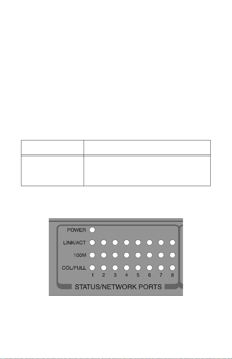
Front Panel LEDs
Figure 3 shows the front panel LEDs; Table 3 d escribes the LED statu s.
Connecting to a high performance workstation, server, or hub
Figure 3
A Close Up of the Front Panel LEDs
3
Page 14
Product Description
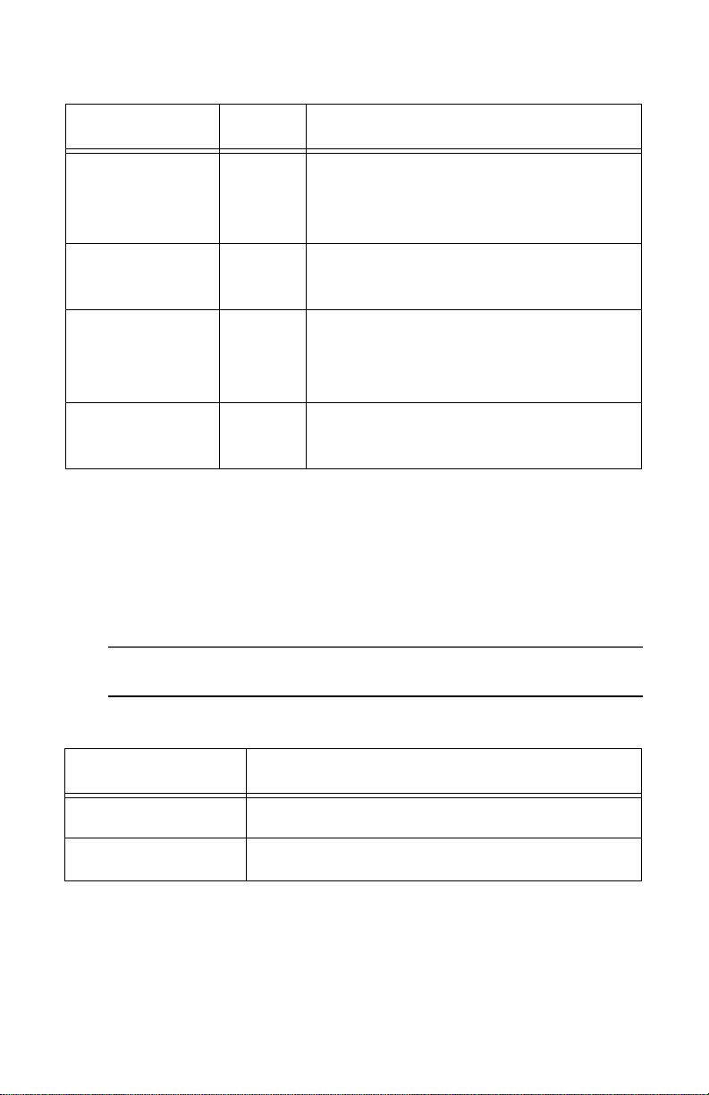
LED Status
Table 3
LEDs Color Description
indicates a valid physical link on the port.
LINK/ACT Green
On
Blinking
means no link.
Off
means the bandwidth is 100 Mbps.
100M Green
COL/FULL Green
On
means the bandwidth is 10 Mbps.
Off
indicates full-duplex transmission mode.
On
Blinking
indicates half-duplex transmission mode.
Off
means there is power to the switch.
POWER Green
On
means there is no power to the switch.
Off
MDI Port
Port 8 is associated with the MDI function.
indicates data is being transmitted.
indicates data collisions in half-duplex mode.
Port 8 gives you the flex ibility of using a s traight-t hrough cable to connect to a
hub or another switch (Port 8 MDI), or to any DTE device (Port 8 MDI-X),
such as an end station or a server.
Note
Use only one Port 8, either Port 8 MDI or Port8 MDI-X.
MDI Ports
Table 4
Port Use
Port 8 MDI
Port 8 MDI-X
4
To connect a hub or another switch to the port
To connect a DTE to the port
Page 15

AT-FS708 and AT-F S708E Ins tall at ion Guide
Power Supply
The AT-FS708 uses a universal internal switching power supply with 100 to
240 VAC, 50/60 Hz input rating. Allied Telesyn ships power cords with the
units to the U.S., Australia, Continental Europe, and the U.K. The
AT-FS708E uses an external power adapter.
Required Voltage
The switches require input of 100 to 240 VAC. Maximum power consumption
is 8.0 W maximum for AT-FS708, and 8.5 W for AT-FS708E.
Auto-Negotiation
The 10/100 Mbps ports are capable of aut o-negotiation:
The ports automatically adapt to the wire speed (10 or 100 Mbps) and duplex
transmission (h alf- or full-d uplex) su pported by th e linked de vice wit hout us er
reconfiguration.
Auto-negotiation is an optional function of the IEEE 802.3u Fast Ethernet
standard that enables devices (switches) to automatica lly exchan ge
information over a link about their speed and duplex abilitie s. This allows
devices to perform automatic configurations to achieve the maximum common
level of operation over a link. Auto-negotiation can provide automatic speed
matching for mu lt ispeed device s a t each end of a link. Multispeed Ethernet
interfaces can then take advantage of the highest speed offered by the 10/100
ports on the switch.
The auto-neg otiation protocol also includes au tomatic negotia tion of duplex
mode, allowing auto-negotiation-capable end-system devices to not only
configure the speed but also change to full-duplex for even higher traffic
throughput. This is particularly useful in environments where NICs are being
replaced or desktop workstations are moved. Each time a new device is
connected to a switch’s port or a device is moved from one port to another,
auto-negotiation will automatically reconfigure each port with o ut an y
intervention from a network administrator.
5
Page 16

Page 17

Chapter 2
Installation
Before You Proceed
Before ins talling the s witch, make sure you read “Trans l ated Safety and
Emission Information” on page 23.
Verifying Package Contents
Make sure that the package includes the following items:
❑
One AT-FS708 or AT-FS708E switch
❑
One AC power cord (AT-FS708) or power adapter (AT-FS708E)
❑
Two rackmounting brackets with screws (AT-FS708 only)
❑
Four self-adhesive rub b er feet
❑
Warranty card
❑
This installation guide
If any of the above items is damaged or missing, contact your representative
immediately.
Note
For wall-mount installation, you must supply the two screws and plastic
anchors or other material necessary to physically mount the switch to
the wall.
7
Page 18

Installation
Site Requirements
Make sure you observe the following site requirements:
❑
Make sure you are placing the switch in a dust-free and moisture-free
environment.
❑
Do not block ventilation openings on the unit. Allow at least 10 cm
(4 in) of space at the front and back of the unit for ventilation.
❑
Make sure that the switch’s power is accessible and cables can be
connected easily.
❑
Cabling should be away from sources of electric al noise such as radios,
transmitters, broadband amplifiers, power lines, and fluorescent
fixtures.
❑
Do not place objects on top of the switch.
❑
Use dedicate d power cir cuits or power cond itione rs to su pply p ower to
the switch.
Desktop Installation
Place the switch on the desktop using these steps, or perform the steps “WallMount Installation” on page 9 or perform the steps “Rack-Mount Installation
(AT-FS708 only)” on page 10. The AT-FS708 (only) can be stacked two or more
devices high on the desktop as described in the steps below.
1. Attach the four self-adhesive rubber feet to the bottom of the switch,
positioning them in the indentations.
2. Place the switch on a flat, level surface where power is easily accessible.
3. To stack more than one switch (for the AT-FS708 only), repeat step 1 for
the additional switches bef ore sta cking them . The rubb er feet cushion the
switch against shock and vibration and provide space between each switch
for ventilation.
Warning
The power cord is used as a disconnecting device. To de-energize
equipment, disconnect the power cord. ! 7
8
Page 19

AT-FS708 and AT-F S708E Ins tall at ion Guide
4. Connect power :
For AT-FS708, attach one end of the power cord to the back of the switch
and the other end to the power source.
For AT-FS708E, plug the power adapter into the power receptacle, then
plug the DC connector to the switch.
5. Make sure the Power LED on the front panel lights green.
6. Attach the data cables and observe normal operation as i ndicated by the
port LEDs. Use only Port 8, either Port 8 MDI or Port 8 MDI-X.
Wall-Mount Installation
For wall-moun t installation, you can pos i tion the switch vertically or
horizontally on the wall using the key hol e cutouts in the bottom of the s w itc h
chassis.
1. If previously attached, remove the rubber feet and all cables and power
cord from the switch.
2. Select a wall location for th e swit ch.
Note
For wall-mount installation, you must supply the two screws and plastic
anchors or other material necessary to physically mount the switch to
the wall.
3. Install two plastic anchors and two pan-head screws into the wall,
separated by 100 mm (approximat ely 4-inches) on center.
4. Position the switch onto the wall screws.
Warning
The power cord is used as a disconnection device. To de-energize
equipment, disconnect the power cord. ! 7
9
Page 20

Installation
5. Connect power:
For AT-FS708, attach one end of the power cord to the back of the switch
and the other end to the power source.
For AT-FS708E, plug the power adapter into the power receptacle, then
plug the DC connector to the switch.
6. Attach the data cables and observe normal operation as indicat ed by the
port LEDs. Use only Port 8, either Port 8 MDI or Port 8 MDI-X.
Note
Auto-negotiation for transmission mode supports full-duplex only if the
connected device also negotiates for full-duplex transmissio n mode.
You are finished with wall-mount installation.
Rack-Mount Installation (AT-FS708 only)
Rackmount installation applies to the AT-FS708 only. You will need a Phillips
screwdriver for this installation.
Caution
Do not use power tools to perform this installation.
1. If previously attached, remove the rubber feet and all cables and power
cord from the switch.
2. Attach the rackmounting brackets to each side of the switch, using the
screws provided.
3. Attach the power cord to the back of the switch.
4. Position the switch in a standard 19-inch rack and secure the switch
brackets to the rack using the 4 large screws provided.
Warning
The power cord is used as a disconnection device. To de-energize
equipment, disconnect the power cord. ! 7
5. Plug the power cord into the power receptacle. Make sure the Power LED
on the front panel lights green.
10
Page 21

AT-FS708 and AT-F S708E Ins tall at ion Guide
6. Attach the data cables and observe normal operation as i ndicated by the
port LEDs. Use only Port 8, either Port 8 MDI or Port 8 MDI-X.
Note
Auto-negotiation for transmission mode sup p orts full-duplex only if the
connected device also negotiates for full-duplex transmission mode.
You are finished with rackmount installation.
Configuration
The following sections discuss standalone, cascade and uplink configurations.
Standalone Configuration
Figure 4 shows the switch connected to end stations and a server. The basic
physical connection for this configuration r equires connecting one of the
switch’s ports to the adapter card of an end station.
X To PC
= To HUB
Figure 4
AT-FS708 Connected to End Stations
11
Page 22

Installation
Cascade Configuration
Cascading means that two switches can be connected together using any of
the switch ports provided you maintain the same medium type. Two switches
can be cascaded to support multiple network port connections. Cable length to
the nodes must follow the 100Base-TX cabling specifications.
To cascade installed switches, do the following:
Note
When cascading switches, you must use the same medium type from
port to port.
1. If you intend to use Port 8, use Port 8 MDI.
2. Use a straight-through UTP RJ-45 cable to connect the first switch to the
second switch. See Figure 5.
X To PC
= To HUB
X To PC
= To HUB
Figure 5
Cascading Switches
3. Check the front panels to make sure that the green Link/Activity LED
lights.
12
Page 23

AT-FS708 and AT-F S708E Ins tall at ion Guide
Uplink Configuration
For 100 Mbps connection to the backbone, use Port 8 MDI. Figure 6 illustrates
how the AT-FS708 switches can be used as an uplink to the backbone in a
typical office complex using Category 5 UTP cable.
CORPORATE BACKBONE
AT-FS708 Switch
AT-FS708 Switch
AT-FS708 Switch
Hub
X To PC
= To HUB
Hub
Sales
X To PC
= To HUB
Hub
Engineering
X To PC
= To HUB
Finance
FORMULA 8200 Switch
Figure 6
MIS
SNMP Station
Switches as Uplink to the Backbone
13
Page 24

Page 25

Chapter 3
Troubleshooting
This chapter describes the procedures to te st and troubleshoot the switches.
Connectivity Testing
In the following procedure, you will test each port for a valid connection and to
confirm the correct operation of the network.
1. Start with Ports 1 and 2. Connect these two ports of a single switch to two
nodes or workstations and turn on the switch power.
2. Wait approximately 1-3 seconds for the auto-negotiation pro c es s to
complete after power-on or after the cables are reconnected.
3. Make sure the Link/Activity and other LEDs of both switch ports are lit.
4. After confirming that Port 1 and Port 2 are operational, reconnect one of
the nodes/workstations to another port, then repeat this connectivity test
with the switch’s remaining ports. Continue to verify the connection in
each port by checking the Link/Activity and other activity LEDs.
Note
Use Port 8 MDI
connected to a hub. Use only one Port 8 at a time.
-X
connected to a workstation. Use Port 8 MDI
15
Page 26

Troubleshooting
Problem Solving
Is the Unit Receiving Power?
Check the P ower LED o n the fron t of the sw itch. This g reen LED shoul d be lit.
Note
The switch performs a self-diagn ostic t est upon powe r on, and takes
about 20 seconds to complete.
If the Power LED is not on, check both ends of the power cord or adapte r .
Make sure the power cord or adapter is plugged into a functioning wall outlet
and that it is properly inserted into the switch’s connector on the back of the
unit.
Is the Link/Activity LED Lit?
The Link LED on the front of the switch lights when a proper connection
between the corresponding 10/100Base-TX port and the equipment connected
to it is established. If this LED is not lit, check for the problems listed below
and make corr ections as necessa ry .
1. Problem 1:
The cable has been cut, damaged, or it is the wrong type of cable.
❑
Solution 1:
— Try making the connection with a different cable. Be sure you are
using an undamaged cable of the correct type.
2. Problem 2:
Connected equipment is not turned on or not operating properly.
❑
Solution 2:
— Check the connected equipment (compute r, anoth er sw itch, etc.)
and turn on the power.
16
Page 27

AT-FS708 and AT-F S708E Ins tall at ion Guide
3. Problem 3:
Port 8 does not wo rk.
❑
Solution 3:
— Connect to only one Port 8, either Port 8 MDI or Port 8 MDI-X.
Make sure you are connected to the correct Port 8.
4. Problem 4:
There is data loss between the switch and one of the connected network
nodes.
❑
Solution 4:
— Make sure that the distance between the switch and the
connected network device is no greater than 100 m (328 ft).
— Make sure you are using Category 5 cable.
17
Page 28

Page 29

Appendix A
Switch Specifications
Physical Characteristics
Chassis Dime nsions: W x D x H
AT-FS708 260 mm x 117 mm x 38 mm
(10.4 in x 4.68 in x 1.5 in)
AT-FS708E 210 mm x 117 mm x 38 mm
(8.4 in x 4.68 in x 1.5 in)
Weight:
AT-FS708 1.95 lbs (0.890 kg)
AT-FS708E 1.5 lbs (0.690 kg)
Operating Temperatures: 0° to 40° C (32° to 104° F)
Storage Temperatures: -25° to 70° C (-13° to 158° F)
Relative Humidity: 5% to 95% (non-condensing)
Operating Altitude: Up to 10,000 ft (3,048 m)
Standards
CE Compliant
Functional: IEEE 802.3 10Base-T Ethernet
IEEE 802.3u, 100Base-TX Fast Ethernet
EMI/RFI: Meets FCC Class B, VCCI Class B, CISPR
Class B, EN55022 Class B
Safety: Conforms to all standa rds normally supported
by Allied Telesyn products, including safety
standards CSA/NRTL (C22.2 950, UL 1950),
TUV/GS (EN60950), CB(IEC60950)
Immunity: EN50082-1
19
Page 30

Switch Specifications
Cabling Specifications
10Base-T: STP/UTP Category 3,4,5 100 ohm impedance
100Base-TX: STP/UTP Category 5 wiring, 100 ohm
impedance
100 m (328 ft) between switch and network node.
Electrical Specifications
AT-FS708 Internal Power: Internal universal power supply with
100 to 240 VAC, 50/60 Hz, 0.3 A input.
AT-FS708E External
Power: External power adapter provides
12 VDC, 1.5 A maximum.
UTP (RJ-45) Connecto r
Figure 7 shows an RJ-45 connector. For a 100Base-TX link between switches,
—any two Medium Attachment Units (MAUs)—you need a crossover cable . For
a connection to a Network Interface Controller (NIC), the cable is wired
straight-through.
Pin 1
Low Last Bit-to-First Delay
For Long Packets: <30 µs
For Short Packets: <18 µs
20
Figure 7
Pin 8
RJ-45 Connector
Page 31

AT-FS708 and AT-F S708E Ins tall at ion Guide
Network Specifications
Table 5 provides an overview of IEEE 802.3 and 802.3u specifications for
10Base-T and 100Base-TX network configuration s using shielded twisted-pair
wiring.
IEEE 802.3 and 802.3u Network Specifications
Table 5
10Base-T 100Base-TX
Media Shielded Twisted Pair
Category 3 or 5
Topology Star, Tree Star, Tree
External Devices Network Adapter Card,
Repeater
Maximum Segment Length 100 m (328 ft) 100 m (328 ft)
Shielded Twisted Pair
Category 5 only
Network Adapter Card,
Repeater
100Base-TX Cable
There are various grades of voice-quality and data-quality cables available.
These can appear to be similar externally, although their high-speed data
transmission characteri stics are radically different.
The identifi c ation problem is ma de worse by some suppliers selling
voice-quality cables as data-quality cables.
If voice-quality cables are used in a 100Base-TX network system, data
movement may be slow, collision-prone or non-existent. In addition, interface
LEDs will usually indicate a valid link in such cases.
Category 5 is required cabling for use with 100Base-TX connections. Using any
other cate gory for a 10 0Base-TX c onnectio n may have hi gh error rate s and may
not have the capacity to transmit data.
21
Page 32

Switch Specifications
100Base-TX Connector Pinouts
Straight-through Cable
1 TX+ TX+ 1
2 TX3 RX+ RX+ 3
Crossover Cable
TX- 2
RX- 66 RX-
1 TX+ TX+ 1
2 TX-
TX- 2
3 RX+ RX+ 3
RX- 66 RX-
22
Page 33

Appendix B
Translated Safety and Emission Information
Important
safety statements in this guide.
Wichtig
enthaltenen Sicherheitshinweise in mehreren Sprachen.
Vigtigt
sikkerhedsadvarslerne i denne håndbog.
Belangrijk
veiligheidsopmerkingen in deze gids.
Important
instructions de sécurité figurant dans ce guide.
Tärkeää
kielellä.
Importante
sicurezza di questa guida.
Viktig
sikkerhetsinformasjonen i denne veiledningen.
Importante
de segurança neste guia.
Importante
mensajes de seguridad incluidos en esta guía.
: This appendix contains multiple-language translations for the
: Dieser Anhang enthält Übersetzungen der in diesem Handbuch
: Dette tillæg ind eholder oversættelser i flere sprog af
: Deze appendix bev at vertalingen i n meerdere talen van de
: Cette annexe contient la traduction en plusieurs langues des
: Tämä liite sisältää tässä oppaassa esiintyvät turvaohjeet usealla
: questa app endice contiene traduzioni i n più lingue degli avvisi di
: Dette tillegget inneholder oversettelser til flere språk av
: Este anexo contém traduções em vários idiomas das advertências
: Este ap éndi c e co nti ene tr ad uc c ion es e n m últ iple s idiomas de lo s
Obs!
Denna bilaga innehåller flerspråkiga översättningar av
säkerhetsmeddelandena i de nna handlednin g.
23
Page 34

Translated Safety and Emission Information
Standards: This produ c t meets the following sta nda rd s.
U.S. Federal Co mmunications Commis s i on
DECLARATION OF CONFORMITY
Manufacture Na me: Allied Telesyn International
Manufacture Address: 960 Stewart Drive, Suite
Manufacture Telephone: 408-730-0950
Declares that the product: Unmanaged, Fast Ethernet Switches
Model Number: AT-FS708 and AT-FS708
This product complies with FCC Part 15B, Class B Limits:
This device complies with part 15 of the FCC Ru les. Operation is subject to
the following two conditions: (1) This device must not cause harmful
interference, and (2) this device must accept any interference received,
including interference that may cause undesired operation.
RADIATED ENERGY
Note: This equipment has been tested and found to comply with the limits
for a Class B digital device pursuant to Part 15 of FCC Rules. These limits
are designed to provide reasonable protection against harmful interference
in a residential installation. This equipment generates, uses and can radiate
radio frequency energy and, if not installed and used in accordance with
instructions, may cause harmful interference to radio or television
reception, which can be determined by turning the equipment off and on.
The user is encouraged to try to correct the interference by one or more of
the following measures:
- Reorient or relocate the receiving antenna.
- Increase the separation between the equipment and the receiver.
- Connect the equipment into an outlet on a circuit different from that to
which the receiver is connected.
- Consult the dealer or an experienced radio/TV techn ic ia n for help.
Changes and modifications not expressly approved by the manufacturer or
registrant of this equipme nt can vo id your authority to operat e this
equipment under Federal Commun ications Commission rules.
Sunnyvale, CA 94086 USA
B
E
!
!
!
24
Industry Canada
This Class B digital apparatus meets all requirements of the Canadian
Interference-Causing Eq uipment Regulations .
Cet appareil numérique de la classe B respecte toutes les exigences du
Règlement sur le matériel brouilleu r du Canada.
1
2
3
RFI Emission EN55022 Class B
Immunity EN50082Electrical Safety EN60950, UL1950, CSA 950
1
Page 35

!
!
!
!
!
!
!
!
!
AT-FS708 and AT-F S708E Ins tall at ion Guide
SAFETY
4
5
6
7
8
9
10
11
12
ELECTRICAL NO TICE S
WARNING: ELECTRIC SHOCK HAZARD
To prevent ELECTRIC shock, do not remove the cover. No user-serviceable
parts inside. This unit contains HAZARDOUS VOLTAGES and should only
be opened by a trained and qualified technician. To avoid the possibility of
ELECTRIC SHOCK, disconnect electric power to the product before
connecting or disconnecting the LAN cables.
LIGHTNING DANGER
DANGER: DO NOT WORK on equipment or CABLES during periods of
LIGHTNING ACTIVIT Y.
INSTALLATION
ELECTRICAL—AUTO VOLTAGE ADJUSTMENT
This product will automatically adjust to any voltage between the ranges
shown on the label
CAUTION: POWER CORD IS USED AS A DI S CONNECTION DEVICE.
TO DE-ENERGIZE EQUIPMENT, disconnect the power cord.
ELECTRICAL - TYPE CLASS 1 EQUI PMENT
THIS EQUIPMENT MUST BE EARTHED. Power plug must be connected
to a properly wired earth ground socket outlet. An improperly wired socket
outlet could place hazardous voltages on accessible metal parts.
PLUGGABLE EQUIPMENT, the socket outlet shall be installed near the
equipment and shall be easily accessible.
CAUTION: Air vents must not be blocked and must have free access to the
room ambient air for cooling.
OPERATING TEMPERATURE: This product is designed for a maximum
ambient temperature of 40° degrees C.
ALL COUNTRIES: Install product in accordance with local and National
Electrical Codes.
25
Page 36

Translated Safety and Emission Information
Normen: Dieses Produkt erfüllt die Anforderungen der nachfolgenden
Normen.
!
!
!
!
!
!
!
!
!
!
!
!
1
2
3
4
5
6
7
8
9
10
11
12
Hochfrequenzstörung EN55022 Klasse B
1
Störsicherheit EN50082Elektrische Sicherheit EN60950, UL1950, CSA 950
SICHERHEIT
ACHTUNG: GEFÄHRLICHE SPANNUNG
Das Gehäuse nicht öffnen. Das Gerät enthält keine vom Benutzer
wartbaren Teile. Das Gerät steht unter Hochspannung und darf nur von
qualifiziertem technischem Personal geöffnet werden. Vor Anschluß der
LAN-Kabel, Gerät vom Netz trennen.
GEFAHR DURCH BL ITZSCHLAG
GEFAHR: Keine Arbeiten am Gerät oder an den Kabeln während eines
Gewitters ausführen.
INSTALLATION
AUTOMATISCHE SPANNUNGSEI NST ELLU NG
Dieses Gerät stellt sich automatisch auf die auf dem Etikett aufgeführten
Spannungswerte ein
VORSICHT: DAS NETZKABEL DIENT ZUM TRENNEN DER
STROMVERSORGUNG. ZUR TRENNUNG VOM NETZ, KABEL AUS
DER STECKDOSE ZIEHEN.
GERÄTE DER KLASSE 1
DIESE GERÄTE MÜSSEN GEERDET SEIN. Der Netzstecker darf nur mit
einer vorschriftsmäßig geerdeten Steckdose verbunden werden. Ein
unvorschriftsmäßiger Ans ch l uß kann die Metallteile des Gehauses unter
gefährliche elektrische Spannungen setzen.
STECKBARES GERÄT: Die Anschlußbuchse sollte in der Nähe der
Einrichtung angebracht werden und leicht zugänglich sein."
VORSICHT
Die Entlüftungsöffnunge n dü rfe n nicht versperrt s e in un d müssen zum
Kühlen freien Zugang zur Raumluft haben.
BETRIEBSTEMPERATUR: Dieses Produkt w urde für den Betrieb in
einer Umgebungstemperatur v on n ich t m ehr al s 40 ° C entwor fen.
ALLE LÄNDER: Installation muß örtlichen und nationalen elektrischen
Vorschriften entsprechen.
26
Page 37

AT-FS708 and AT-F S708E Ins tall at ion Guide
Standarder: Dette prod uk t tilfred sstiller de følgen de sta ndarder.
!
!
!
!
!
!
!
!
!
!
!
!
1
2
3
4
5
6
7
8
9
10
11
12
Radiofrekvens forsty r rels esemissionEN55022
Immunitet EN50082-1
Elektrisk sikkerhed EN60950, UL1950, CSA 950
SIKKERHED
ELEKTRISKE FORHOLDSREG LER
ADVARSEL: RISIKO FOR ELEKTRISK STØD
For at forebygge ELEKTRISK stød, undlad at åbne apparatet. Der er ingen
indre dele, der kan repareres af brugeren. Denne enhed indeholder
LIVSFARLIGE STRØMSPÆNDINGER og bør kun åbnes af en uddannet
og kvalificeret tekniker. For at undgå risiko for ELEKTRISK STØD,
afbrydes den elektriske strøm til produktet, før LAN-kablerne monteres
eller afmonteres.
FARE UNDER UVEJR
FARE: UNDLAD at arbejde på udstyr eller KABLER i perioder med
LYNAKTIVITET.
INSTALLATION
ELEKTRISK -- AUTOMATISK SPÆNDING SREGULERING
Dette apparat vil automatisk tilpasse sig enhver spænding indenfor de
værdier, der er angivet på e tiketten.
ADVARSEL: DEN STRØMFØRENDE LEDNING BRUGES TIL AT
AFBRYDE STRØMMEN. SKAL STRØMMEN TIL APPARATET
AFBRYDES, tages ledningen ud af sti kk et.
ELEKTRISK - KLASSE 1-UDSTYR
DETTE UDSTYR KRÆVER JORDFORBINDELSE. Stikk et ska l være
forbundet med en korrekt installeret jordforbunden stikkontakt. En
ukorrekt installeret stikkontakt kan sætte livsfarlig spænding til
tilgængelige metaldele.
UDSTYR TIL STIKKONTA K T, stikk ontak ten bø r installer es n ær ved
udstyret og skal være lettilgængelig.
ADVARSEL: Ventilationsåbninger må ikke blokeres og skal have fri
adgang til den omgivende luft i rummet for afkøling.
BETJENINGSTEMPERATUR: Dette apparat er konstrueret til en
omgivende temperatur på maksimum 40 grader C.
ALLE LANDE: Installation af produktet skal ske i overensstemmelse med
lokal og nationa l lovgivning for elektriske installationer.
Klasse B
27
Page 38

Translated Safety and Emission Information
Eisen: Dit product voldoet aan de volgende eisen.
!
!
!
!
!
!
!
!
!
!
!
!
1
2
3
4
5
6
7
8
9
10
11
12
RFI Emissie EN55022 Klasse B
Immuniteit EN50082Electrische Veiligheid EN60950, UL1950, CSA 950
VEILIGHEID
WAARSCHUWINGEN MET BETREKKING TOT ELEKTRICITEIT
WAARSCHUWING: GEVAAR VOOR ELEKTRISCHE SCHOKKEN
Verwijder het deksel niet, teneinde ELEKTRISCHE schokken te
voorkomen. Binnenin bevinden zic h geen onderdelen die door de gebruiker
onderhouden kunnen worden. Dit toestel staat onder GEVAARLIJK
SPANNING en mag alleen worden geopend door een daartoe opgeleide en
bevoegde technicus. Om het gevaar op ELEKTRISCHE SCHOKKEN te
vermijden, moet u het toestel van de stroombron ontkoppele n alvorens de
LAN-kabels te koppelen of ontkoppelen.
GEVAAR VOOR BLIKSEMINSLAG
GEVAAR: NIET aan toestellen of KABELS WERKEN bij BLIKSEM.
INSTALLATIE
ELEKTRISCH: AUTOMATISCHE AANPASSING VAN DE
SPANNING
Dit toestel past zich automatisch aan elke spanning aan, tussen de op het
label vermelde waarden.
WAARSCHUWING: HET TOESTEL WORDT UITGESCHAKELD DOOR
DE STROOMKABEL TE ONTKOPPELEN.OM HET TOESTEL
STROOMLOOS TE M A KEN: de stroomkabel ontkoppelen.
ELEKTRISCHE TOESTELLEN VAN KLASSE 1
DIT TOESTEL MOET GEAARD WORDEN. De stekker moet aangesloten
zijn op een juist geaarde contactdoos. Een onjuist geaarde contactdoos kan
de metalen onderdelen waarme e de gebruiker eventueel in aan raking komt
onder gevaarlijke spanning s tel len.
AAN TE SLUITEN APPARATUUR, de contactdoos wordt in de nabijheid
van de apparatuur geïnstalleerd en is gemakkelijk te bereiken."
OPGELET: De ventilatiegaten mogen niet worden gesperd en moeten de
omgevingslucht ongehinderd toelaten voor afkoeling.
BEDRIJFSTEMPERATUUR: De omgevingstemperatuur voor dit
produkt mag niet meer bedragen dan 40 graden Celsius.
ALLE LANDEN: het toestel installeren overeenkomstig de lokale en
nationale elektrische voorschriften.
1
28
Page 39

AT-FS708 and AT-F S708E Ins tall at ion Guide
Normes: ce produit est conforme aux normes de suivantes:
!
!
!
!
!
!
!
!
!
!
!
!
1
2
3
4
5
6
7
8
9
10
11
12
Emission d’interférenc es
radioélectriques EN55022 Classe B
Immunité EN50082 - 1
Sécurité électrique EN60950, UL1950, CSA 950
SÉCURITÉ
INFORMATION SUR LES RISQUES ÉLEC TRIQU ES
AVERTISSEMEN : DANGER D’ÉLECTROCUTION
Pour éviter toute ÉLECTROCUTION, ne pas ôter le revêtement protecteur
du matériel. Ce matériel ne contient aucun élément répara ble par
l’utilisateur. Il comprend des TENSIONS DANGEREUSES et ne doit être
ouvert que par un technicien dûment qualifié. Pour éviter tout risque
d’ÉLECTROCUTION, débrancher le matériel avant de connecter ou de
déconnecter les câbles LAN.
DANGER DE FOUDRE
DANGER: NE PAS MANIER le matériel ou les CÂBLES lors d’activité
orageuse.
INSTALLATION
RÉGLAGE DE TENSION AUTOMATIQUE ÉLECTRIQUE
Ce matériel peut s'ajus ter automatiquement sur n'importe quelle tension
comprise dans la plage indiquée su r l'étiquette.
ATTENTION: LE CORDON D’ALIMENTATION SERT DE MISE HORS
CIRCUIT. POUR COUPER L’ALIMENTATIO N DU MATÉRIEL,
débrancher le cordon.
ÉQUIPEMENT DE CLASSE 1 ÉLECTRIQUE
CE MATÉRIEL DOIT ÊTRE MIS A LA TERRE. La prise de courant doit
être branchée dans une prise femelle correctement mise à la terre car des
tensions dangereuses risqueraient d’atteindre les pièces métalliques
accessibles à l’utilisateur.
EQUIPEMENT POUR BRANCHEMENT ELECTRIQUE, la prise de sortie
doit être placée près de l’équipement et facilement accessible".
ATTENTION: Ne pas bloquer les fentes d’aération , ceci empêcherait l’air
ambiant de circuler librement pour le refroidissement.
TEMPÉRATURE DE FONCTIONNEMENT: Ce matériel est capable de
tolérer une température ambiante maximum de ou 40 de grés Celsius.
POUR TOUS PAYS: Installer le matériel conformément aux normes
électriques nationales et locales.
29
Page 40

Translated Safety and Emission Information
Standardit: Tämä tuote on seuraavien standardien mukainen.
!
!
!
!
!
!
!
!
!
!
!
!
1
2
3
4
5
6
7
8
9
10
11
12
Radioaaltojen häirintä EN55022 Luokka B
Kestävyys EN50082Sähköturvallisuus EN60950, UL1950, CSA 950
TURVALLISUUS
SÄHKÖÖN LIITTYVI Ä HUO MA UTU KSIA
VAROITUS: SÄHKÖISKUVAARA
Estääksesi SÄHKÖISKUN älä poista kantta. Sisällä e i ole käyttäjän
huollettavissa olevia osia. Tämä laite sisältää VAARALLISIA
JÄNNITTEITÄ ja sen voi avata vain koulutettu ja pätevä teknikko.
Välttääksesi SÄHKÖISKUN mahdollisuuden katkaise sähkövirta
tuotteeseen ennen kuin liität tai irrotat paikallisverkon (LAN ) kaapelit.
SALAMANISKUVAARA
HENGENVAARA: ÄLÄ TYÖSKENTELE laitteiden tai KAAPELEIDEN
KANSSA SALAMOINNIN AIKANA.
ASENNUS
SÄHKÖ - AUTOMAATTINEN JÄNNITTEENSÄÄT
Tämä tuote säätää automaattisesti mihin tahansa jännitteeseen
ohjetarrassa annettujen arvoj en välillä.
HUOMAUTUS: VIRTAJOHTOA KÄYTETÄÄN
VIRRANKATKAISULAI T TE ENA. VIRTA KATKAISTAAN irrottamalla
virtajohto.
SÄHKÖ - TYYPPILUOKAN 1 LAITTEET
TÄMÄ LAITE TÄYTYY MAADOITTAA. Pistoke täytyy liittää kunnollisesti
maadoitettuun pistorasiaan. Virheellisesti johdotettu pistorasia voi altistaa
metalliosat vaarallisille jännitteille.
PISTORASIAAN KYTKETTÄV Ä LA ITE; pistorasia on asennettava
laitteen lähelle ja siihen on oltava esteetön pääsy."
HUOMAUTUS: Ilmavaihtoreikiä ei pidä tukkia ja niillä täytyy olla vapaa
yhteys ympäröivään huoneilmaan, jotta ilmanvaihto tapahtuisi.
KÄYTTÖLÄMPÖTILA: Tämä tuote on suunniteltu ympäröivän ilman
maksimilämpötilalle 40°C.
KAIKKI MAAT: Asenna tuote paikallisten ja kansallisten
sähköturvallisuusmääräyste n mukaise sti.
1
30
Page 41

AT-FS708 and AT-F S708E Ins tall at ion Guide
Standard: Questo prodotto è conforme ai seguenti st andard
!
!
!
!
!
!
!
!
!
!
!
!
1
2
3
4
5
6
7
8
9
10
11
12
Emissione RFI (interferenza di
radiofrequenza) EN55022 Classe B
Immunità EN50082-1
Sicurezza elettrica EN60950, UL1950, CSA 950
NORME DI SICUREZZA
AVVERTENZE ELETTRICHE
ATTENZIONE: PERICOLO DI SCOSSE ELETTRICHE
Per evitare SCOSSE ELETTRICHE non asportare il coperchio. Le
componenti interne non sono riparabili dall’utente. Questa unità ha
TENSIONI PERICOLOSE e va aperta solamente da un tecnico
specializzato e qualificato. Per evitare og ni possibilità di SCOSSE
ELETTRICHE, interrompere l’alimentazione del dispositivo prima di
collegare o staccare i cavi LAN.
PERICOLO DI FULMINI
PERICOLO: NON LAVOR A RE sul dispositivo o sui CAVI durante
PRECIPITAZIONI TEMPORALESCHE.
INSTALLAZIONE
ELETTRICITÀ - REG O LA ZI ON E AUTO MAT I CA DELLA
TENSIONE
Questo prodotto regolerà automat icamente la tens io ne ad un valore
compreso nella gamma indicata sull'etichetta
ATTENZIONE: IL CAVO DI ALIMENTAZIONE È USATO COM
DISPOSITIVO DI DISATTIVAZIONE. PER TOGLIERE LA CORRENTE
AL DISPOSITIVO staccare il cavo di alimentazione.
ELETTRICITÀ - DISPOSITIVI DI CLASSE 1
QUESTO DISPOSITIVO DEVE AVERE LA ME SSA A TERRA. La spina
deve essere inserita in una presa di corrente specificamente dotata di messa
a terra. Una presa non cablata in maniera co rr etta risc hia di scaricare una
tensione pericolosa su parti metalliche accessibili.
APPARECCHIATURA C OLLEGABILE, la presa va installata vicino
all’apparecchio per risultare facilmente accessibile".
ATTENZIONE: le prese d’aria non vanno ostruite e devono consentire il
libero ricircolo dell’aria ambiente per il raffreddamento.
TEMPERATURA DI FUNZIONAMENTO: Questo prodotto è concepito
per una temperatura ambientale massima di 40 gradi centigradi.
TUTTI I PAESI: installare il prodotto in conformità delle vigenti
normative elettriche nazionali.
31
Page 42

Translated Safety and Emission Information
Sikkerhetsnormer: Dette produktet tilfredsstiller følgende
sikkerhetsnormer.
!
!
!
!
!
!
!
!
!
!
!
!
1
2
3
4
5
6
7
8
9
10
11
12
RFI stråling EN55022 Klasse B
1
Immunitet EN50082Elektrisk sikkerhet EN60950, UL1950, CSA 950
SIKKERHET
ELEKTRISITET
ADVARSEL: FARE FOR ELEKTRISK SJOKK
For å unngå ELEKTRISK sjokk, må dekslet ikke tas av. Det finnes ingen
deler som brukeren kan rep arere på innsid en. Denne enheten i nn ehol der
FARLIGE SPENNINGER , og må kun åpnes av en faglig kvalifisert
tekniker. For å unngå ELEKTRISK SJOKK må den elektriske strømmen til
produktet være avslått før LAN-kablene til- eller frakobles.
FARE FOR LYNNEDSLAG
FARE: ARBEID IKKE på utstyr eller KABLER i TORDENVÆR.
INSTALLASJON
ELEKTRISK - AUTO SPENNINGSTILPASNING
Dette produktet vil automatisk bli tilpasset hvilken som helst
strømspenning i de områdene som vises på etiketten.
FORSIKTIG: STRØMLEDNINGEN BRUKES TIL Å FRAKOBLE
UTSTYRET. FOR Å DEAKTIVISERE UTSTYRET, må strømforsyningen
kobles fra.
ELEKTRISK - TYPE 1- KLASSE UTSTYR
DETTE UTSTYRET MÅ JORDES. Strømkontakten må være tilkoplet en
korrekt jordet kontakt. En kontakt som ikke er korrekt jordet kan f øre til
farlig spenninger i lett t ilgjengelige metalldeler.
UTSTYR FOR STIKKONTAKT. Stikkontakten skal monteres i nærheten
av utstyret og skal være lett tilgjengelig."
FORSIKTIG: Lufteventilene må ikke blokkeres, og må ha fri tilgang til
luft med romtemperatur for avkjøling.
DRIFTSTEMPERA TUR: Dette produktet er konstruert for bruk i
maksimum romtemperatur på 40 grader celsius.
ALLE LAND: Produktet må installeres i samsvar med de lokale og
nasjonale elektriske koder.
32
Page 43

AT-FS708 and AT-F S708E Ins tall at ion Guide
Padrões: Este produto atende aos seguintes padrões.
!
!
!
!
!
!
!
!
!
!
!
!
1
2
3
4
5
6
7
8
9
10
11
12
Emissão de interferência de
radiofrequência EN55022 Classe B
Imunidade EN50082-1
Segurança Eléctrica EN60950, UL1950, CSA 950
SEGURANÇA
AVISOS SOBRE CARACTERÍSTICAS ELÉTRICAS
ATENÇÃO: PERIGO DE CHOQUE ELÉTRICO
Para evitar CHOQUE ELÉ TR ICO, não retire a tampa. Não contém peças
que possam ser consertadas pelo usuário. Este aparelho c ontém
VOLTAGENS PERIGOSAS e só deve ser aberto por um técnico qualificado
e treinado. Para evitar a possibilidade de CHOQUE ELÉTRICO,
desconecte o aparelho da fonte de energia elétrica antes de conectar e
desconectar os cabos da LAN.
PERIGO DE CHOQ UE CA US AD O POR RAIO
PERIGO: NÃO TRABALHE no equipamento ou nos CABOS durante
períodos suscetíveis a QUEDAS DE RAIO.
INSTALAÇÃO
ELÉTRICO - AJUSTE AUTOMÁTICO DE VOLTAGE
Este produto ajustar-se-á automaticamente a qualquer voltagem que esteja
dentro dos limites indicados no rótulo.
CUIDADO: O CABO DE ALIMENTAÇÃO É UTILIZADO COMO UM
DISPOSITIVO DE DESCONEXÃO. PARA DESELETRIFICAR O
EQUIPAMENTO, desconecte o cabo de ALIMENTAÇÃO.
ELÉTRICO - EQUIPAMENTOS DO TIPO CLASSE 1
DEVE SER FEI TA LIGAÇÃO DE FIO TERRA PARA ESTE
EQUIPAMENTO. O plugue de alimentação deve ser conectado a uma
tomada com adequada ligação de fio terra. Tomadas sem adequada ligação
de fio terra podem transmitir voltagens perigosas a peças metálicas
expostas.
EQUIPAMENTO DE LIGAÇÃO, a tomada eléctrica deve estar instalada
perto do equipamento e ser de fácil acesso."
CUIDADO: As aberturas de ventilação não devem ser bloqueadas e devem
ter acesso livre ao ar ambiente para arrefecimento adequado do aparelho.
TEMPERATURA DE FUNCIONAMENTO: Este produto foi projetado
para uma temperatura ambiente máxima de 40 graus centígrados.
TODOS OS PAÍSES: Instale o produto de acordo com as normas nacionais
e locais para instalações elétricas.
33
Page 44

Translated Safety and Emission Information
Estándares: Este producto cumple con los siguientes estándares.
!
!
!
!
!
!
!
!
!
!
!
!
1
2
3
4
5
6
7
8
9
10
11
12
Emisión RFI EN55022 Clase B
Inmunidad EN50082Seguridad eléctrica EN60950, UL1950, CSA 950
SEGURIDAD
AVISOS ELECT RIC OS
ADVERTENCIA: PELIGRO DE ELECTROCHOQUE
Para evitar un ELECT R OCHOQUE, no quite la tapa. No hay ningún
componente en el interior al cual puede prestar servicio el usuario. Esta
unidad contiene VOLTAJES PELIGROSOS y sólo deberá abrirla un técnico
entrenado y calificado. Para evitar la posibilidad de ELECTROCHOQUE
desconecte la corriente eléctrica que llega al producto antes de conectar o
desconectar los cables LAN.
PELIGRO DE RAYOS
PELIGRO: NO REALICE NINGUN TIPO DE TRABAJO O CONEXION
en los equipos o en LOS CABLES durante TORMENTAS ELECTRICAS.
INSTALACION
ELECTRICO - AUTO-AJUSTE DE TENSION
Este producto se ajustará automáticamente a cualquier tensión entre los
valores máximos y mínimos indicados en la etiqueta.
ATENCION: EL CABLE DE ALIMENTACION SE USA COMO UN
DISPOSITIVO DE DESCONEXION. PARA DESACTIVAR EL EQUIPO,
desconecte el cable de alimentación.
ELECTRICO - EQUIPO DEL TIPO CLASE 1
ESTE EQUIPO TIENE QUE TEN ER CONEXION A TIERRA. El cable
tiene que conectarse a un enchufe a tierra debidamente instalado. Un
enchufe que no está correctamente instalado podría ocasionar tensiones
peligrosas en las partes metálica s que están expuestas.
EQUIPO CONECTABLE, el tomacorriente se debe instalar cerca del
equipo, en un lugar con acceso fácil".
ATENCION: Las aberturas para ventilación no deberán bloquearse y
deberán tener acceso libre al aire ambiental de la sala para su enfriamiento.
TEMPERATURA RE QUERIDA PARA LA OPERACIÓ N: Este producto
está diseñado para una temperatura ambi ental máxima de 40 grados C.
PARA TODOS LOS PAÍSES: Monte el producto de acuerdo con los
Códigos Eléctricos locales y nacionales.
1
34
Page 45

AT-FS708 and AT-F S708E Ins tall at ion Guide
Standarder: Denna produkt uppfyller följande standarder.
!
!
!
!
!
!
!
!
!
!
!
!
1
2
3
4
5
6
7
8
9
10
11
12
Radiostörning EN55022 Klass B
Immunitet EN50082-1
Elsäkerhet EN60950, UL1950, CSA 950
SÄKERHET
TILLKÄNNAGIVANDEN BETRÄFF AN DE ELEKTRIC ITETS RISK:
RISK FÖR ELEKTRISK STÖT För att undvika ELEKTRISK stöt, ta ej
av locket. Det finns inga delar inuti som behöver underhållas. Denna
apparat är under HÖGSPÄNNING och får endast öppn as av en utbildad
kvalificerad tekniker. För att undvika ELEKTRISK S TÖT, koppla ifrån
produktens strömanslutning innan LAN-kablarna ansluts eller kopplas ur.
FARA FÖR BLIXTNEDSLAG
FARA: ARBETA EJ på ut rustningen eller kablarna vid Å SKVÄDER.
INSTALLATION
ELEKTRISKT - AUTOMATISK SPÄNNINGSJUSTERIN
Denna produkt justeras automatisk t till alla spänningar inom omfånget
som indikeras på prod uktens märkning.
VARNING: NÄTKABELN ANVÄNDS SOM STRÖMBRYTARE FÖR ATT
KOPPLA FRÅN STRÖMMEN, dra ur nätkabeln.
ELEKTRISKT - TYP KLASS 1 UTRUSTNING
DENNA UTRUSTNING MÅSTE VARA JORDAD. Nätkabeln må ste vara
ansluten till ett ordentligt jordat uttag. Ett felaktigt uttag kan göra att
närliggande metalldelar utsätts för högspänning. Apparaten skall anslutas
till jordat uttag, när den ansluts till ett nätverk.
UTRUSTNING MED PLUGG . Uttaget skall installeras i utrustningens
närhet och vara lättåtkomligt".
VARNING: Luftventile rna får ej blockeras och måste ha fri tillgång till
omgivande rumsluft för avsvalning.
DRIFTSTEMPERATUR
Denna produkt är konstruerad för rumstemp eratu r ej ö vers tig an de 40
grader Celsius
Alla länder: Installera produkten i enlighet med lokala och statliga
bestämmelser för elektrisk utrustning.
35
Page 46

Page 47

Appendix C
Technical Support Fax Order
Name_________________________________________________________________________
Company ______________________________________________________________________
Address _______________________________________________________________________
City_____________________________State/Province ___________________________________
Zip/Postal Code _______________________Country ___________________________________
Phone___________________________________ Fax ___________________________________
Incident Summary
Model number of Allied Telesyn product I am using _____________________________________
Network software products I am using________________________________________________
_______________________________________________________________________
Brief summary of problem _________________________________________________________
_______________________________________________________________________
Conditions (List the steps that led up to the problem.) ______ __ __ _________________________
_______________________________________________________________________
_______________________________________________________________________
Detailed description (Use separate sheet, if necessary)
_______________________________________________________________________
_______________________________________________________________________
_______________________________________________________________________
When completed, fax this sheet to the appropriate Allied Telesyn office. Fax numbers can be found
on page viii.
37
Page 48

Page 49

Appendix D
AT-FS708 and AT-FS708E Switches Installation Feedback
Please tell us what additional informatio n y ou would like to see discu ssed in
the guide. If there are topics you would like information on that were not
covered in the guide, please photocopy this page, answer the questions and fax
or mail this form back to Allied Telesyn International Corp. The mailing
address and fax number are at the bottom of the page. Your comments are
valuable when we plan future revisions of the guide.
I found the following the most valuable __________________________________
______________________________________________________________________
______________________________________________________________________
______________________________________________________________________
I would like the following more developed ________________________________
______________________________________________________________________
______________________________________________________________________
______________________________________________________________________
I would find the guide more useful if ____________________________________
______________________________________________________________________
______________________________________________________________________
Please fax or mail your feedback. Fax to 1-408-736-01 00 . Or mail to:
Allied Telesyn International, Corp.
c/o Technical Communications
960 Stewart Drive, Suite B
Sunnyvale, CA 94086 USA
PN 613-10864-00 Rev A
39
Page 50

 Loading...