

Page 1

AT-FS705PD
Fast Ethernet Switch
Installation Guide
PN 613-50465-00 Rev B
Page 2

Copyright © 2004 Allied Telesyn, Inc.
960 Stewart Drive Suite B, Sunnyvale CA 94085, USA
All rights reserved. No part of this publication may be reproduced without prior written
permission from Allied Telesyn, Inc.
Ethernet is a registered trademark of Xerox Corporation. All other product names,
company names, logos or other designations mentioned herein are trademarks or
registered trademarks of their respective owners.
Allied Telesyn, Inc. reserves the right to make changes in specifications and other
information contained in this document without prior written notice. The information
provided herein is subject to change without notice. In no event shall Allied Telesyn,
Inc. be liable for any incidental, special, indirect, or consequential damages whatsoever,
including but not limited to lost profits, arising out of or related to this manual or the
information contained herein, even if Allied Telesyn, Inc. has been advised of, known, or
should have known, the possibility of such damages.
Page 3

Electrical Safety and Emission Compliance Statements
Standards: This product meets the following standards:
U.S. Federal Communications Commission
Declaration Of Conformity
Manufacturer Name: Allied Telesyn, Inc.
Manufacturer Address: 960 Stewart Drive, Suite B
Manufacturer Telephone: 408-730-0950
Declares that the product: Fast Ethernet Switch
Model Numbers: AT-FS705PD
This product complies with FCC Part 15B, Class B Limits:
This device complies with part 15 of the FCC Rules. Operation is subject
to the following two conditions: (1) This device must not cause harmful
interference, and (2) this device must accept any interference received,
including interference that may cause undesired operation.
Radiated Energy
Note: This equipment has been tested and found to comply with the limits
for a Class B digital device pursuant to Part 15 of FCC Rules. These
limits are designed to provide reasonable protection against harmful
interference in a residential installation. This equipment generates, uses
and can radiate radio frequency energy and, if not installed and used in
accordance with instructions, may cause harmful interference to radio or
television reception, which can be determined by turning the equipment
off and on. The user is encouraged to try to correct the interference by one
or more of the following measures:
- Reorient or relocate the receiving antenna.
- Increase the separation between the equipment and the receiver.
- Connect the equipment into an outlet on a circuit different from that to
which the receiver is connected.
- Consult the dealer or an experienced radio/TV technician for help.
Changes and modifications not expressly approved by the manufacturer
or registrant of this equipment can void your authority to operate this
equipment under Federal Communications Commission rules.
Sunnyvale, CA 94085 USA
Industry Canada
This Class B digital apparatus meets all requirements of the Canadian
Interference-Causing Equipment Regulations.
Cet appareil numérique de la classe B respecte toutes les exigences du
Règlement sur le matériel brouilleur du Canada.
iii
Page 4

Electrical Safety and Emission Compliance Statements
RFI Emission FCC Class B, EN55022 Class B,
Immunity EN55024
Electrical Safety EN60950 (TUV), UL60950 (
Important: Appendix B contains translated safety statements for installing
this equipment. When you see the
safety statement in your language.
Wichtig: Anhang B enthält übersetzte Sicherheitshinweise für die
Installation dieses Geräts. Wenn Sie
den übersetzten Sicherheitshinweis in Ihrer Sprache nach.
Vigtigt: Tillæg B indeholder oversatte sikkerhedsadvarsler, der vedrører
installation af dette udstyr. Når De ser symbolet
B og finde de oversatte sikkerhedsadvarsler i Deres eget sprog.
Belangrijk: Appendix B bevat vertaalde veiligheidsopmerkingen voor het
installeren van deze apparatuur. Wanneer u de
Appendix B voor vertaalde veiligheidsinstructies in uw taal.
Important: L'annexe B contient les instructions de sécurité relatives à
l'installation de cet équipement. Lorsque vous voyez le symbole
reportez-vous à l'annexe B pour consulter la traduction de ces instructions
dans votre langue.
Tärkeää: Liite B sisältää tämän laitteen asentamiseen liittyvät käännetyt
turvaohjeet. Kun näet
liitteestä B.
Importante: l’Appendice B contiene avvisi di sicurezza tradotti per
l’installazione di questa apparecchiatura. Il simbolo
l’Appendice B per l’avviso di sicurezza nella propria lingua.
Viktig: Tillegg B inneholder oversatt sikkerhetsinformasjon for installering
av dette utstyret. Når du ser
oversatte sikkerhetsinformasjonen på ønsket språk.
Importante: O Anexo B contém advertências de segurança traduzidas para
instalar este equipamento. Quando vir o símbolo
segurança traduzida no seu idioma no Anexo B.
Importante: El Apéndice B contiene mensajes de seguridad traducidos
para la instalación de este equipo. Cuando vea el símbolo
Apéndice B para ver el mensaje de seguridad traducido a su idioma.
Obs! Bilaga B innehåller översatta säkerhetsmeddelanden avseende
installationen av denna utrustning. När du ser
för att läsa det översatta säkerhetsmeddelandet på ditt språk.
-symbolin, katso käännettyä turvaohjetta
VCCI Class B, C-TICK
2
, go to Appendix B for the translated
sehen, schlagen Sie in Anhang B
, åpner du til Tillegg B for å finne den
1
), CE 3
cULus
, skal De slå op i tillæg
ziet, raadpleeg
,
, indica di consultare
, leia a advertência de
, vaya al
, skall du gå till Bilaga B
iv
Page 5

Table of Contents
Electrical Safety and Emission Compliance Statements .....................iii
Table of Contents ............................................................................................v
Welcome to Allied Telesyn ..........................................................................vii
Where to Find Related Guides.........................................................................vii
Documentation Conventions............................................................................vii
Contacting Allied Telesyn ...............................................................................viii
Online Support .........................................................................................viii
E-mail and Telephone Support................................................................viii
Returning Products ..................................................................................viii
For Sales or Corporate Information........................................................viii
Chapter 1
Overview ........................................................................................................... 1
Key Features.......................................................................................................2
Status LEDs........................................................................................................3
Powering Options ........................................................................................4
Twisted Pair Ports..............................................................................................4
Port Speed........................................................................................................... 5
Duplex Mode ....................................................................................................... 5
Auto MDI/MDI-X................................................................................................ 6
MAC Address Table............................................................................................ 6
Store and Forward.............................................................................................. 7
Network Topologies ............................................................................................8
Standalone...................................................................................................8
Uplink .......................................................................................................... 9
Chapter 2
Installation .....................................................................................................11
Verifying the Package Contents ......................................................................11
Planning the Installation.................................................................................12
Selecting a Site.......................................................................................... 13
Reviewing Safety Guidelines....................................................................14
v
Page 6

Installing the Switch on a Desktop..................................................................15
Wall-Mounting the Switch ...............................................................................17
Warranty Registration .....................................................................................20
Chapter 3
Troubleshooting ............................................................................................21
Appendix A
Technical Specifications .............................................................................23
Physical .............................................................................................................23
Environmental..................................................................................................23
Electrical Rating...............................................................................................23
Agency Compliance...........................................................................................24
Pinout Assignments..........................................................................................24
Appendix B
Translated Safety and Emission Information ........................................27
vi
Page 7

Welcome to Allied Telesyn
This guide contains instructions on how to install and configure the
AT-FS705PD Fast Ethernet Switch.
Where to Find Related Guides
The Allied Telesyn web site at www.alliedtelesyn.com offers you an easy
way to access the most recent documentation, software, and technical
information for all of our products. For product guides, select “Support &
Services” from our web site.
Documentation Conventions
This guide uses the following conventions:
Note
Notes provide additional information.
Caution
Cautions indicate that performing or omitting a specific action may
result in equipment damage or loss of data.
Warning
Warnings indicate that performing or omitting a specific action may
result in bodily injury.
vii
Page 8

Welcome to Allied Telesyn
Contacting Allied Telesyn
This section provides Allied Telesyn contact information for technical support
as well as sales or corporate information.
Online Support
You can request technical support online by accessing the Allied Telesyn
Knowledge Base from the following web site: http://kb.alliedtelesyn.com.
You can use the Knowledge Base to submit questions to our technical support
staff and review answers to previously asked questions.
E-mail and Telephone Support
For Technical Support via E-mail or telephone, refer to the Support & Services
section of the Allied Telesyn web site: http://www.alliedtelesyn.com.
Returning Products
Products for return or repair must first be assigned a Return Materials
Authorization (RMA) number. A product sent to Allied Telesyn without a
RMA number will be returned to the sender at the sender’s expense.
To obtain a RMA number, contact Allied Telesyn’s Technical Support at our
web site: http://www.alliedtelesyn.com.
For Sales or Corporate Information
You can contact Allied Telesyn for sales or corporate information at our web
site: http://www.alliedtelesyn.com. To find the contact information for your
country, select “Contact Us” then “Worldwide Contacts.”
viii
Page 9

Chapter 1
Overview
The AT-FS705PD is a 5-port Unmanaged Fast Ethernet Switch that includes
one Power-Over-Ethernet (POE) port. This switch is considered a Class 1
Powered Device (PD) and can be used in pair with any IEEE 802.3af/D4.3 or
later compliant Power Sourcing Equipment (PSE).
This switch offers a range of features and capabilities that can be used in a
variety of network configurations and topologies. It also serves the following
functions:
❑ Creating small workgroups with dedicated 10 megabits per second
(Mbps) and 100 Mbps links to your network devices, such as
workstations, servers, printers, and routers.
❑ Interconnecting Ethernet hubs or switches to provide a bridge
between the different workgroups of your network.
❑ Connecting to other Ethernet switches so that they can be part of a
larger Ethernet network.
❑ Maximizing your existing network by providing full-duplex operation
over a twisted pair port.
❑ Receiving both data and power through its POE port.
The POE port allows data and power be transmitted over the same single
twisted pair cable without power sourcing consideration or electric rewires.
The AT-FS705PD switch features five 10/100 Mbps twisted pair ports with
one port dedicated for POE operation. Each twisted pair port has an RJ-45
connector with a maximum operating distance of 100 meters (328 feet). The
twisted pair port can operate at 10 Mbps or 100 Mbps and in half- or fullduplex mode.
The AT-FS705PD switch can be used on a desktop or mounted on a wall. The
switch is easy to install and does not require software configuration or
management.
1
Page 10
Overview
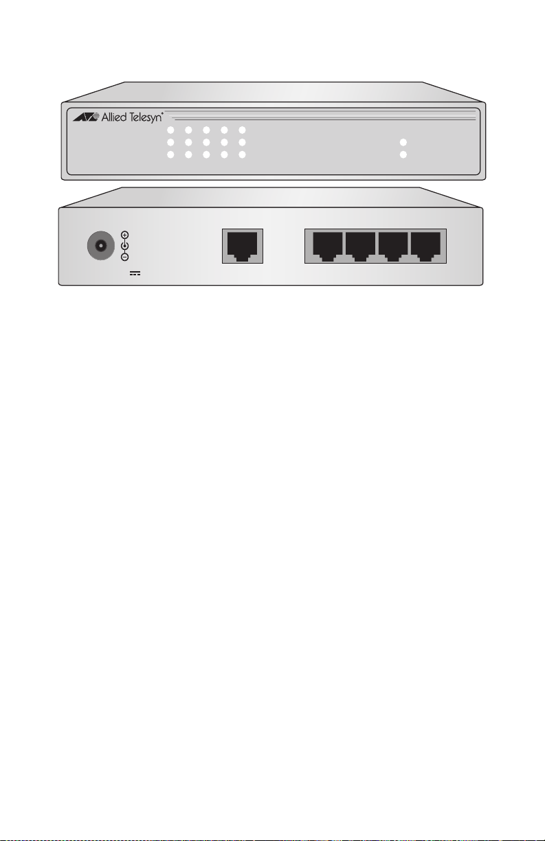
Figure 1 illustrates the front and back panels of the AT-FS705PD switch.
54321
POE
LINK/ACT
100M
FDX
AT-FS705PD
5 Port Fast Ethernet Switch
Powered Device
24V D C 12345
Figure 1 AT-FS705PD Switch Front and Back Panels
Key Features
The AT-FS705PD switch has the following key features:
❑ Five 10/100Base-TX ports using RJ-45 twisted pair connectors
❑ Power-Over-Ethernet PD Support
❑ System and port LEDs
❑ Auto MDI/MDI-X on all ports
PWR
POE
WALL
❑ Auto-Negotiation on all ports (IEEE 802.3u-compliant)
❑ Non-blocking architecture
❑ Store and forward packet handling
❑ Backpressure and flow control (IEEE 802.3x-compliant)
❑ Storage for up to 2,048 MAC addresses with aging time at 300 seconds
❑ Maximum frame size of 1536 Byte
❑ For use on a desktop or wallmount
2
Page 11

Status LEDs
Table 1 defines the LEDs for the switch.
Table 1 Status LEDs
LED Color Description
AT-FS705PD Fast Ethernet Switch Installation Guide
LINK/ACT Green
OFF
Blinking
100M Green
OFF
FDX Green
OFF
Table 2 defines the LEDs for the power of the switch.
PWR LED Color Description
POE Green
OFF/
Blinking
WALL Green
OFF
A valid link has been established on the port.
No link has been established on the port.
Data is being received or transmitted on the port.
The port is operating at 100 Mbps.
The port is operating at 10 Mbps.
The port is operating in full-duplex mode.
The port is operating in half-duplex mode.
Table 2 Power Status LEDs
The switch is powered with the Power-Over-Ethernet feature via
Port 5.
The switch is not powered with the Power-Over-Ethernet feature
via Port 5.
The switch is powered with a wall adapter.
The switch is not powered with a wall adapter.
3
Page 12
Overview
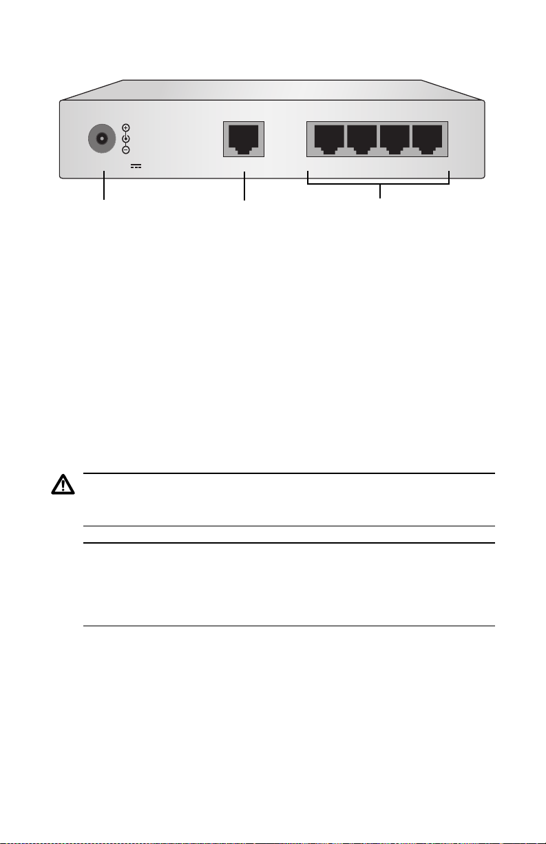
Powering Options
24V D C 12345
POE
POE Port24VDC Power Port
Twisted Pair Ports
Figure 2 Power Port, POE Port, and Twisted Pair Ports on Back Panel
Two ways to power on an AT-FS705PD switch are as follows:
❑ Option 1: Powered by a 24VDC @ 0.3A+ output wall adapter.
Option 1 has higher priority, if both options are connected to the
AT-FS705PD, then it is powered by Option 1 and the PWR WALL LED
is green. In the same time, the PWR POE LED is either blinking or
OFF, which is fully controlled by the Power Sourcing Equipment
(PSE).
❑ Option 2: Powered-over-Ethernet on Port 5.
Option 2 will be enabled only if an IEEE 802.3af compliant PSE is
connecting to Port 5, and no power plug is inserted in the 24VDC
power port.
Caution
POE and power cord are used as disconnection devices: To de-energize
equipment, disconnect the POE and the power cord.
Note
The AT-FS705PD Switch is classified as IEEE Std 802.3af-2003,
Environment A, where a LAN or LAN segment, with all its associated
interconnected equipment, is entirely contained within a single lowvoltage power distribution system and within a single building.
Twisted Pair Ports
The AT-FS705PD switch has five 10Base-T/100Base-TX twisted pair ports.
Each twisted pair port features a RJ-45 connector. The maximum operating
distance for the twisted pair ports is 100 meters (328 feet) when operating at
either 10 Mbps or 100 Mbps.
4
Page 13

AT-FS705PD Fast Ethernet Switch Installation Guide
Port Speed
The twisted pair ports are compliant with the 10Base-T and 100Base-TX
standards and are capable of either 10 Mbps or 100 Mbps operation. Since the
ports are IEEE 802.3u Auto-Negotiation compliant, the switch will set the
port speed automatically. With Auto-Negotiation, the speed of the ports are
set automatically by the switch after it determines the speed of the end-node
connected to the port. Auto-Negotiation is designed to ensure that the port on
the switch and the end-node are operating at the same speed and that they
are communicating at the highest possible common speed between the
devices. For example, if an end-node is capable of only 10 Mbps, the switch
then sets the port connected to the end-node to 10 Mbps.
Duplex Mode
Duplex mode refers to the way an end-node sends and receives data on the
network. An end-node can operated in either half- or full-duplex mode
depending on its capabilities. An end-node that is operating in half-duplex
mode can either send data or receive data, but it cannot do both at the same
time. An end-node that is operating in full-duplex mode can send and receive
data simultaneously. The best network performance is achieved when an endnode can operate at full-duplex, since the end-node is able to send and receive
data simultaneously.
Each twisted pair port on the AT-FS705PD switch can operate in either halfduplex or full-duplex mode. Since these twisted pair ports are IEEE 802.3ucompliant, the duplex mode can be set automatically through AutoNegotiation. With Auto-Negotiation, if the end-node is capable of full-duplex,
the port is set automatically to full-duplex mode. If the end-node is capable of
half-duplex, the port is set automatically to half-duplex mode.
Note
In order for a twisted pair port on the AT-FS705PD switch to
successfully Auto-Negotiate its duplex mode with an end-node, the endnode should also be using Auto-Negotiation. Otherwise, a duplex mode
mismatch can occur. The twisted pair port, using Auto-Negotiation, will
default to half-duplex if it detects that the end-node is not using AutoNegotiation. This will result in a mismatch if the end-node is operating
at a fixed duplex mode of full-duplex.
5
Page 14

Overview
Auto MDI/MDI-X
A twisted pair port on a 10 Mbps or 100 Mbps Ethernet network device can
have one of two possible wiring configurations: MDI or MDI-X. A twisted pair
port on a PC, router, or bridge is typically wired as MDI, while a twisted pair
port on a switch or hub is usually MDI-X.
To connect two 10 Mbps or 100 Mbps network devices together that have
dissimilar port wiring configurations, such as an MDI to MDI-X, you would
use a straight-through twisted pair cable. To connect two networks devices
that have the same wiring configuration, such as MDI to MDI, you would use
a crossover cable.
The AT-FS705PD switch features automatic MDI/MDI-X. The twisted pair
port automatically determines the configurations of the port on the device to
which it is connected and then configures itself appropriately. For example, if
a port on a switch is connected to a port on a bridge, which is typically wired
as MDI, the port on the switch automatically configures itself as MDI-X. This
feature allows you to use either a crossover cable or a straight-through cable
when connecting a device to a twisted pair port.
MAC Address Table
The heart of an Ethernet switch is the Media Access Control (MAC) address
table. Every device that you attach to an Ethernet network has a MAC
address. This address is assigned to the device by the device’s manufacturer.
For example, each Network Interface Card (NIC) that you install into your
network computers has a MAC address that was assigned to it by the card’s
manufacturer.
A switch’s MAC address table is a list of the MAC addresses of the devices
that are connected to its ports. The switch uses this table to direct data frames
to their appropriate destination end-nodes, and in some cases, to discard
frames that it receives. The switch creates the MAC address table by
examining the frames that it receives on its ports. Each frame is examined for
its source address; that is, the MAC address of the end-node that sent the
frame. The switch checks to determine whether the address is already in its
MAC address table. If it is not, the switch adds the address to the table along
with the port number on which the frame was received. The result is a table
that contains a list of all the MAC addresses of end-nodes that have sent
frames to the switch and the ports on the switch to which the end-nodes are
connected.
6
Page 15

AT-FS705PD Fast Ethernet Switch Installation Guide
The switch also checks the destination MAC address of each frame it receives.
The destination address is the MAC address of the end-node to which the
frame is intended. If the address is in the table, the switch directs the frame
directly to the port where the end-node is located. This helps to ensure that
end-nodes will only receive traffic that is intended for them and not have to
deal with traffic intended for other end-nodes.
If the destination address is not in the MAC address table, the switch
broadcasts the frame to all switch ports. When the destination end-node
responds, the switch will be able to match the address to a port so that the
next time a frame is destined to that particular end-node, the switch will be
able to forward the frame to the correct port instead of having to broadcast the
frame to all ports.
In some cases a switch will even discard a frame. If the switch receives a
frame that is destined to an end-node on the same port on which the frame
was received, the switch discards the frame.
The MAC address table in the AT-FS705PD switch can store up to 2,048 MAC
addresses. To prevent the table from becoming filled with addresses of endnodes that are no longer active, the switch has a MAC address aging timer.
This timer will delete a MAC address from the table if it does not see a frame
from the end-node with the address on any port after five minutes (300
seconds). The aging timer also helps to ensure that the table is correct should
an end-node be moved from one port on the switch to another port.
Store and Forward
The AT-FS705PD switch supports store and forward switching at Fast
Ethernet full-wire speed. Packets entering each port are stored in buffers.
Once the full packet is received, the switch will forward or discard the packet,
depending on its destination address and error status. This ensures that only
error-free packets destined for another segment will be transferred across the
switch, reducing network load. For example, if the packet entering from Port 1
is destined for an end-node on Port 2, the switch forwards the frame if the
frame does not contain any errors. If the packet from Port 1 is destined for an
end-node also connected to Port 1, the packet is discarded.
7
Page 16

Overview
Network Topologies
The AT-FS705PD switch can be used in different topologies such as
standalone and uplink. Each topology is describe below.
Standalone
A standalone topology uses one switch to connect the end-nodes. Figure 3
illustrates a standalone topology that uses an AT-FS705PD switch to connect
several workstations and a server.
Power Sourcing Equipment (PSE)
RS-232 TERMINAL PORT
1
S
S
A
L
C
T
C
U
D
O
R
P
R
E
S
A
L
E
R
A
T
S
T
O
N
O
D
M
A
E
B
O
T
N
I
B
T
R
O
P
A
T
AT-8024GB
10Base-T/100Base-TX Fast Ethernet Swi
Link
Mode
Link
Mode
AT-FS705PD
POE
ch
t
R
O
P
MODE
COL
LINK
100
FULL
MODE
ACT
FAULT
MASTER
LINK
PWR
MODE
24VD C 12345
10/100 Mbps
10/100 Mbps
(receiving/transmitting
both power and data)
Figure 3 Standalone Topology
8
Page 17

AT-FS705PD Fast Ethernet Switch Installation Guide
Uplink
Figure 4 illustrates multiple AT-FS705PD switches can be interconnected
using uplinks from a centralized backbone Fast Ethernet switch.
Power Sourcing Equipment (PSE)
T
R
O
P
L
A
N
I
M
R
E
T
2
3
2
S
R
1
S
S
A
L
C
T
C
U
D
O
R
P
R
E
S
A
L
E
R
A
T
S
T
O
N
O
D
M
A
E
B
O
T
N
I
B
T
R
O
B
4G
2
AT-80
t E
s
a
F
X
T
e
s
a
B
0
0
T/1
-
e
as
0B
1
nk
Li
e
od
M
nk
Li
de
o
M
P
A
T
R
O
P
ch
t
i
w
t S
e
rn
he
t
E
OD
M
L
O
C
0
0
1
L
L
U
F
T
C
A
T
L
U
A
F
R
E
T
S
K
A
N
I
M
L
K
N
I
L
R
W
P
E
D
O
M
E
D
O
M
AT-FS705PD
POE
24VDC 12345
10/100 Mbps
10/100 Mbps
(receiving/transmitting
both power and data)
AT-FS705PD
POE
24VDC 12345
AT-FS705PD
POE
24VDC 12345
Figure 4 Uplink Topology
9
Page 18

Page 19

Chapter 2
Installation
This chapter contains the installation instructions for the AT-FS705PD
switch. This switch can be used on a desktop or mounted on a wall.
Verifying the Package Contents
Make sure the following items are included in your package. If any item is
missing or damaged, contact your Allied Telesyn sales representative for
assistance.
❑ One AT-FS705PD Fast Ethernet Switch
❑ Two plastic wall anchor
❑ Two self-tapping screws
❑ Four protective rubber feet (for desktop use only)
❑ This installation guide
❑ Warranty card
11
Page 20

Installation
Planning the Installation
Be sure to observe the following guidelines when planning the installation of
your switch.
❑ The end-nodes connected to the twisted pair ports can operate at 10
Mbps or 100 Mbps and half or full-duplex. The switch uses AutoNegotiation to determine the correct speed and duplex mode for each
port.
❑ The end-nodes connected to the ports on the switch can be a network
adapter card, hub, repeater, router, or another switch.
❑ The twisted pair port cabling must be kept away from sources of
electrical noise, such as radios, transmitters, power lines, broadband
amplifiers electrical motors, and fluorescent fixtures.
❑ A twisted pair port using the Auto-Negotiation feature to configure
the Auto MDI/MDI-X. It configures itself automatically as MDI or
MDI-X when connected to an end-node. Either a straight-through or
crossover twisted pair cable can be used to connect a switch port to any
network device.
Refer to Table 3 for the cabling specifications for the twisted pair ports.
Table 3 10Base-T/100Base-TX Twisted Pair Port Cabling Specifications
Operating Mode Twisted Pair Cable Maximum Operating
Distance
10Base-T Shielded or Unshielded Category 3 or better 100 m (328 ft)
100Base-TX Shielded or Unshielded Category 5 or better 100 m (328 ft)
12
Page 21

AT-FS705PD Fast Ethernet Switch Installation Guide
Selecting a Site
Be sure to observe the following requirements when choosing a site for your
switch.
❑ Select a site that is dust-free and moisture-free.
❑ Be sure that the site will allow you to easily access the switch’s power
and data cables.
❑ Make sure that the switch is placed on a flat, secure surface (such as
a desk or table) if you want to use it with desktop configuration.
❑ Make sure the air flow around the switch and through its vents on the
side and back are not restricted.
❑ Be sure that the twisted pair port cabling is kept away from sources of
electrical noise; such as radios, transmitters, power lines, broadband
amplifiers, electrical motors, and fluorescent fixtures.
❑ Use a dedicated power circuit or a power conditioner to supply reliable
power to the switch.
13
Page 22

Installation
Reviewing Safety Guidelines
Please review the following safety guidelines before installing the
AT-FS705PD switch.
Warning
Lightning Danger: Do not work on this equipment or cables during
periods of lightning activity. 4
Caution
Pluggable Equipment: The socket outlet should be installed near the
equipment and should be easily accessible. 5
Caution
Air Vents: The air vents must not be blocked on the unit and must have
free access to the room ambient air for cooling. 6
Caution
Operating Temperature: This product is designed for a maximum
ambient temperature of 40°C. 7
Caution
All Countries: Install this product in accordance with local and
National Electric Codes. 8
14
Page 23

AT-FS705PD Fast Ethernet Switch Installation Guide
Installing the Switch on a Desktop
The AT-FS705PD switch can be used on a desktop or mounted on a wall. To
wall-mount the switch, refer to “Wall-Mounting the Switch” on page 17.
To install an AT-FS705PD switch on a desktop, perform the following
procedure:
1. Remove all equipment from the package and store the packaging material
in a safe location.
2. If you are installing the switch on a desktop, attach the four protective
feet to the bottom on the unit. See Figure 5.
Note
Do not attach the protective feet if you are wall-mounting the switch.
WALL
POE
PWR
54321
FDX
100M
LINK/ACT
Powered Device
5 Port Fast Ethernet Switch
AT-FS705PD
Figure 5 Attaching the Protective Feet
3. Place the switch on a flat, secure surface (such as a desk or table) leaving
ample space around the unit for ventilation.
4. Connect the twisted pair cables to the twisted pair ports.
When connecting a twisted pair cable to a port, observe the following
guidelines:
❑ An RJ-45 connector should fit snugly into the port on the converter.
The tab on the connector should lock the connector into place.
❑ You should check to be sure that you are using the appropriate type of
twisted pair cabling. Refer to Table 3 on page 12 for twisted pair cable
specifications.
❑ Since the twisted pair port, when operating in Auto-Negotiation, is
Auto MDI/MDI-X, you can use either a straight-through or crossover
twisted pair cable to connect any type of network device to a port on
the converter. If you disable Auto-Negotiation on the port, the port
defaults to MDI-X.
15
Page 24

Installation
Caution
POE and power cord are used as disconnection devices: To de-energize
equipment, disconnect the POE and the power cord.
5. There are two ways to power ON the switch; perform one of the following
steps:
❑ Using a wall power adapter: Plug one end of the power cord to the
24VDC power connector on the back of the switch and the other end of
the power cord to a power outlet.
❑ Using the POE port: Plug one end of the twisted pair cable to the POE
port on the back of the switch and the other end of the twisted pair
cable to an Ethernet port on a PSE device.
Note
The AT-FS705PD Switch is classified as IEEE Std 802.3af-2003,
Environment A, where a LAN or LAN segment, with all its associated
interconnected equipment, is entirely contained within a single lowvoltage power distribution system and within a single building.
6. Verify that either the PWR POE or WALL LED is green. If the LED is
OFF, refer to “Troubleshooting” on page 21 for instructions.
7. Power ON the end-nodes connected to the switch.
8. Check the LINK/ACT LEDs for each port is green. If a LED is OFF, refer
to “Troubleshooting” on page 21 for instructions.
The switch is now ready for use.
16
Page 25

AT-FS705PD Fast Ethernet Switch Installation Guide
Wall-Mounting the Switch
The switch can be mounted horizontally on a wall using the keyholes on the
bottom of the switch. The screws, plastic anchors, and other materials
necessary to mount the switch on a wall are not provided.
To wall-mount the switch, perform the following procedure:
1. If attached, remove the rubber feet, data cables, and power cord from the
switch.
2. Select a wall location for the device.
3. Install two plastic anchors and two screws onto the wall, as illustrated in
Figure 6.
L
L
A
W
E
O
P
R
W
P
5
FDX
4
32
100M
1
LINK/ACT
h
c
it
w
e
S
t
ic
e
v
n
e
r
e
D
h
d
t
e
D
E
r
t
e
P
s
w
a
5
o
F
P
0
t
r
7
o
P
S
5
-F
T
A
Figure 6 Installing The Plastic Anchors and Screws Onto The Wall
17
Page 26

Installation
4. Position the switch horizontally onto the wall screws, as illustrated in
Figure 7.
E
R
O
P
PW
L
L
A
CT
K/A
LIN
100M
X
FD
54
3
21
witch
D
t S
P
5
erne
0
th
7
ice
t E
S
ev
as
-F
T
d D
ort F
A
ere
5 P
ow
P
W
Figure 7 Positioning The Switch Onto The Wall Screws
5. Connect the twisted pair cables to the twisted pair ports.
When connecting a twisted pair cable to a port, observe the following
guidelines:
❑ An RJ-45 connector should fit snugly into the port on the switch. The
tab on the connector should lock the connector into place.
❑ You should check to be sure that you are using the appropriate type of
twisted pair cabling. Refer to Table 3 on page 12 for twisted pair cable
specifications.
❑ Since the twisted pair port, when operating in Auto-Negotiation, is
Auto MDI/MDI-X, you can use either a straight-through or crossover
twisted pair cable to connect any type of network device to a port on
the converter.
Caution
POE and power cord are used as disconnection devices: To de-energize
equipment, disconnect the POE and the power cord.
18
Page 27

AT-FS705PD Fast Ethernet Switch Installation Guide
6. Power ON the switch.
There are two ways to power ON the switch; perform one of the following
steps:
❑ Using a wall power adapter: Plug one end of the power cord to the
24VDC power connector on the back of the switch and the other end of
the power cord to a power outlet.
❑ Using the POE port: Make sure that no power plug is inserted in the
24VDC power port. Then plug one end of the twisted pair cable to the
POE port on the back of the switch and the other end of the twisted
pair cable to an Ethernet port on a PSE device.
7. Verify that either the PWR POE or WALL LED is green. If the LED is
OFF, refer to “Troubleshooting” on page 21 for instructions.
8. Power ON the end-nodes connected to the switch.
9. Check the LINK/ACT LEDs for each port is green. If a LED is OFF, refer
to “Troubleshooting” on page 21 for instructions.
The switch is now ready for use.
19
Page 28

Installation
Warranty Registration
When you have finished installing the switch, you should register your switch
by completing the enclosed warranty card and sending it in.
20
Page 29

Chapter 3
Troubleshooting
Follow the guidelines below to test and troubleshoot the installation in the
event a problem occurs.
If the PWR-POE LED is OFF and Port 5 is connected to a PSE device, do the
following;
Note
This twisted pair cable connecting to the POE port must be a Category 5
Ethernet cable.
❑ Make sure that the PSE device is IEEE 802.3af/D4.3 or later
compliant.
❑ Make sure that the PSE device is detecting the AT-FS705PD switch.
❑ Make sure that the CAT5 cable is functional.
❑ Make sure there is no power plug inserted in the 24VDC power port
on the back panel of the switch.
If the PWR-WALL LED is OFF and the AT-FS705PD switch is connected to a
wall adapter, do the following;
❑ Make sure that the wall adapter has an output capability of 24VDC @
0.3A.
❑ Make sure that the wall adapter has the same output polarity as the
one shown on the AT-FS705PD switch, refer to Figure 1 on page 2.
If a LINK/ACT LED is OFF, do the following:
❑ Check that the end-node connected to the port is powered ON and is
operating properly.
❑ Check that the twisted pair cable is securely connected to the port on
the switch and to the port on the end-node.
21
Page 30

Troubleshooting
❑ Verify that the end-node connected to the port and the switch are
operating at the same speed. Both must be operating at either 10
Mbps or 100 Mbps.
❑ Make sure that the twisted pair cable does not exceed 100 meters (328
feet) and that you are using a Category 3 or better cable for 10Base-T
operation or a Category 5 or better cable for 100Base-TX operation.
If there is a communication problem between the end-nodes connected to the
switch, do the following:
❑ Verify that the end-nodes are operating with the same duplex mode.
If you are still experiencing problems after testing and troubleshooting the
installation, refer to “Contacting Allied Telesyn” on page viii or visit our web
site at www.alliedtelesyn.com for support information.
22
Page 31

Appendix A
Technical Specifications
Physical
Dimensions: W x H x D
125.73 mm x 26 mm x 100.05 mm
(4.95 in x 1.02 in x 3.74 in)
Weight: 372 grams (0.82 lbs)
Environmental
Operating Temperature: 0° C to 40° C (32° F to 104° F)
Storage Temperature: -25° C to 70° C (-13° F to 158° F)
Operating Humidity: 5% to 90% non-condensing
Storage Humidity: 5% to 95% non-condensing
Operating and Storage Altitude: Up to 3,048 meters (10,000 feet)
Electrical Rating
Input Supply Voltage: 24VDC
Input Current: 0.3A
POE Input Voltage: 22 - 57VDC
POE Current: 66mA - 140mA
Power Consumption: 3W maximum (Class 1)
23
Page 32

Technical Specifications
Agency Compliance
EMI/RFI: FCC Class B, EN55022 Class B,
VCCI Class B, C-TICK
Electrical Safety: EN60950 (TUV), UL60950 (
Immunity: EN55024
cULus)
, CE
Pinout Assignments
Figure 8 shows the pinout assignments for the RJ-45 connector.
8
1
Figure 8 RJ-45 Pin Assignments
Table 4 lists the RJ-45 connector pins and their signals used in Port 1 - Port 4
when these port are operating in either MDI or MDI-X configuration.
Table 4 RJ-45 Pin Signals used in Ports 1 - 4
MDI-X (Default) Signal MDI Signal
1RX+1 TX+
2RX-2 TX-
8
1
3TX+3 RX+
4- 4 -
5- 5 -
6TX-6 RX-
7- 7 -
8- 8 -
24
Page 33

AT-FS705PD Fast Ethernet Switch Installation Guide
Table 5 lists the RJ-45 connector pins and their signals used in Port 5 when
this port is connected to a PSE device using a straight cable.
Table 5 Port 5 RJ-45 Pin Signals (using straight cable)
PSE PWR
Configuration
Alternative A
(MDI)
PSE side
Alternative A
(MDI-X)
PSE side
Alternative A
(MDI)
PSE side
Alternative A
(MDI-X)
Pin Number Port 5 Signals (*)
1
RX+ and
Vport-1
2RX- and
Vport-1
3
TX+ and
Vport-2
TX+ and
Vport-1
TX- and
Vport-1
RX+ and
Vport-2
RX+ TX+
RX- TX-
TX+ RX+
4 - - Vport+ Vport+
5 - - Vport+ Vport+
6TX- and
Vport-2
RX- and
Vport-2
TX- RX-
7 - - Vport- Vport-
8-- Vport- Vport-
(*) Vport-1 can be either Vport + or Vport-, depending on the PSE device.
Vport-2 can be either Vport+ or Vport-, depending on the PSE device.
If Vport-1 = Vport +, then Vport-2 = Vport-, and if Vport-1 = Vport -, then Vport-2 = Vport+.
PSE side
25
Page 34

Technical Specifications
Table 6 lists the RJ-45 connector pins and their signals used in Port 5 when
this port is connected to a PSE device using a cross-over cable.
Table 6 Port 5 RJ-45 Pin Signals (using cross-over cable)
PSE PWR
Configuration
Alternative A
(MDI)
PSE side
Alternative A
(MDI-X)
PSE side
Alternative A
(MDI)
PSE side
Alternative A
(MDI-X)
Pin Number Port 5 Signals (*)
1
TX+ and
Vport-1
2TX- and
Vport-1
3
RX+ and
Vport-2
RX+ and
Vport-1
RX- and
Vport-1
TX+ and
Vport-2
TX+ RX+
TX- RX-
RX+ TX+
4 - - Vport+ Vport+
5 - - Vport+ Vport+
6RX- and
Vport-2
TX- and
Vport-2
RX- TX-
7 - - Vport- Vport-
8-- Vport- Vport-
(*) Vport-1 can be either Vport + or Vport-, depending on the PSE device.
Vport-2 can be either Vport+ or Vport-, depending on the PSE device.
If Vport-1 = Vport +, then Vport-2 = Vport-, and if Vport-1 = Vport -, then Vport-2 = Vport+.
PSE side
26
Page 35

Appendix B
Translated Safety and Emission Information
Important: This appendix contains multiple-language translations for the
safety statements in this guide.
Wichtig: Dieser Anhang enthält Übersetzungen der in diesem Handbuch
enthaltenen Sicherheitshinweise in mehreren Sprachen.
Vigtigt: Dette tillæg indeholder oversættelser i flere sprog af
sikkerhedsadvarslerne i denne håndbog.
Belangrijk: Deze appendix bevat vertalingen in meerdere talen van de
veiligheidsopmerkingen in deze gids.
Important: Cette annexe contient la traduction en plusieurs langues des
instructions de sécurité figurant dans ce guide.
Tärkeää: Tämä liite sisältää tässä oppaassa esiintyvät turvaohjeet usealla
kielellä.
Importante: questa appendice contiene traduzioni in più lingue degli avvisi
di sicurezza di questa guida.
Viktig: Dette tillegget inneholder oversettelser til flere språk av
sikkerhetsinformasjonen i denne veiledningen.
Importante: Este anexo contém traduções em vários idiomas das
advertências de segurança neste guia.
Importante: Este apéndice contiene traducciones en múltiples idiomas de los
mensajes de seguridad incluidos en esta guía.
Obs! Denna bilaga innehåller flerspråkiga översättningar av
säkerhetsmeddelandena i denna handledning.
27
Page 36

Translated Safety and Emission Information
Standards: This product meets the following standards.
U.S. Federal Communications Commission
Declaration Of Conformity
Manufacturer Name: Allied Telesyn, Inc.
Manufacturer Address: 960 Stewart Drive, Suite B
Manufacturer Telephone: 408-730-0950
Declares that the product: Fast Ethernet Switch
Model Numbers: AT-FS705PD
This product complies with FCC Part 15B, Class B Limits:
This device complies with part 15 of the FCC Rules. Operation is subject
to the following two conditions: (1) This device must not cause harmful
interference, and (2) this device must accept any interference received,
including interference that may cause undesired operation.
Radiated Energy
Note: This equipment has been tested and found to comply with the
limits for a Class B digital device pursuant to Part 15 of FCC Rules.
These limits are designed to provide reasonable protection against
harmful interference in a residential installation. This equipment
generates, uses and can radiate radio frequency energy and, if not
installed and used in accordance with instructions, may cause harmful
interference to radio or television reception, which can be determined by
turning the equipment off and on. The user is encouraged to try to correct
the interference by one or more of the following measures:
- Reorient or relocate the receiving antenna.
- Increase the separation between the equipment and the receiver.
- Connect the equipment into an outlet on a circuit different from that to
which the receiver is connected.
- Consult the dealer or an experienced radio/TV technician for help.
Changes and modifications not expressly approved by the manufacturer
or registrant of this equipment can void your authority to operate this
equipment under Federal Communications Commission rules.
Sunnyvale, CA 94085 USA
28
Industry Canada
This Class B digital apparatus meets all requirements of the Canadian
Interference-Causing Equipment Regulations.
Cet appareil numérique de la classe B respecte toutes les exigences du
Règlement sur le matériel brouilleur du Canada.
Page 37

AT-FS705PD Fast Ethernet Switch Installation Guide
1RFI Emission FCC Class B, EN55022 Class B,
VCCI Class B, C-TICK
2 Immunity EN55024
3 Electrical Safety EN60950 (TUV), UL60950 (
cULus
), CE
4 Lightning Danger
Danger: DO NOT WORK on equipment or CABLES during periods of
LIGHTNING ACTIVITY.
5 Pluggable equipment, the socket outlet shall be installed near the
equipment and shall be easily accessible.
6 Caution: Air vents must not be blocked and must have free access to the
room ambient air for cooling.
7 Operating Temperature: This product is designed for a maximum
ambient temperature of 40 degrees C.
8 All Countries: Install product in accordance with local and National
Electrical Codes.
29
Page 38

Translated Safety and Emission Information
Normen: Dieses Produkt erfüllt die Anforderungen der nachfolgenden
Normen.
1 Hochfrequenzstörung FCC Klasse B, EN55022 Klasse B,
VCCI Klasse B, C-TICK
2 Störsicherheit EN55024
3 Elektrische Sicherheit EN60950 (TUV), UL60950 (
cULus
), CE
4 Gefahr Durch Blitzschlag
Gefahr: Keine Arbeiten am Gerät oder an den Kabeln während eines
Gewitters ausführen.
5Steckbares Gerät: Die Anschlußbuchse sollte in der Nähe der Einrichtung
angebracht werden und leicht zugänglich sein."
6Vorsicht
Die Entlüftungsöffnungen dürfen nicht versperrt sein und müssen zum
Kühlen freien Zugang zur Raumluft haben.
7 Betriebstemperatur
Dieses Produkt wurde für den Betrieb in einer Umgebungstemperatur von
nicht mehr als 40° C entworfen.
8Alle Länder: Installation muß örtlichen und nationalen elektrischen
Vorschriften entsprechen.
30
Page 39

AT-FS705PD Fast Ethernet Switch Installation Guide
Standarder: Dette produkt tilfredsstiller de følgende standarder.
1Radiofrekvens
forstyrrelsesemission FCC Klasse B, EN55022 Klasse B,
VCCI Klasse B, C-TICK
2 Immunitet EN55024
3 Elektrisk sikkerhed EN60950 (TUV), UL60950 (
cULus
), CE
4 Fare Under Uvejr
Fare: UNDLAD at arbejde på udstyr eller KABLER i perioder med
LYNAKTIVITET.
5 Aan te sluiten apparatuur, de contactdoos wordt in de nabijheid van de
apparatuur geïnstalleerd en is gemakkelijk te bereiken."
6Opgelet: De ventilatiegaten mogen niet worden gesperd en moeten de
omgevingslucht ongehinderd toelaten voor afkoeling
7 Betjeningstemperatur: Dette apparat er konstrueret til en omgivende
temperatur på maksimum 40 grader C.
8 Alle Lande: Installation af produktet skal ske i overensstemmelse med
lokal og national lovgivning for elektriske installationer.
31
Page 40

Translated Safety and Emission Information
Eisen: Dit product voldoet aan de volgende eisen.
1RFI Emissie FCC Klasse B, EN55022 Klasse B,
VCCI Klasse B, C-TICK
2 Immuniteit EN55024
3 Electrische Veiligheid EN60950 (TUV), UL60950 (
cULus
), CE
4 Gevaar Voor Blikseminslag
Gevaar: NIET aan toestellen of KABELS WERKEN bij BLIKSEM.
5 Equipement pour branchement electrique, la prise de sortie doit être placée
près de l’équipement et facilement accessible".
6Attention: Ne pas bloquer les fentes d’aération, ceci empêcherait l’air
ambiant de circuler librement pour le refroidissement
7 Bedrijfstemperatuur: De omgevingstemperatuur voor dit produkt mag
niet meer bedragen dan 40 graden Celsius.
8Alle Landen: het toestel installeren overeenkomstig de lokale en nationale
elektrische voorschriften.
32
Page 41

AT-FS705PD Fast Ethernet Switch Installation Guide
Normes: Ce produit est conforme aux normes de suivantes.
1 Emission d'interférences
radioélectriques FCC Classe B, EN55022 Classe B,
VCCI Classe B, C-TICK
2 Immunité EN55024
3 Sécurité électrique EN60950 (TUV), UL60950 (
4 Danger De Foudre
5 EQUIPEMENT POUR BRANCHEMENT ELECTRIQUE, la prise de sortie
6 Attention: Ne pas bloquer les fentes d’aération, ceci empêcherait l’air
Danger: NE PAS MANIER le matériel ou les CÂBLES lors d'activité
orageuse.
doit être placée près de l’équipement et facilement accessible".
ambiant de circuler librement pour le refroidissement.
cULus
7 Température De Fonctionnement
Ce matériel est capable de tolérer une température ambiante maximum de
40 degrés Celsius.
8 Pour Tous Pays: Installer le matériel conformément aux normes
électriques nationales et locales.
), CE
33
Page 42

Translated Safety and Emission Information
Standardit: Tämä tuote on seuraavien standardien mukainen.
1 Radioaaltojen häirintä FCC Luokka B, EN55022 Luokka B,
VCCI Luokka B, C-TICK
2 Kestävyys EN55024
3 Sähköturvallisuus EN60950 (TUV), UL60950 (
cULus
), CE
4 Salamaniskuvaara
Engenvaara: ÄLÄ TYÖSKENTELE laitteiden tai KAAPELEIDEN
KANSSA SALAMOINNIN AIKANA.
5 Pistorasiaan kytkettävä laite; pistorasia on asennettava laitteen lähelle ja
siihen on oltava esteetön pääsy."
6 Huomautus: Ilmavaihtoreikiä ei pidä tukkia ja niillä täytyy olla vapaa
yhteys ympäröivään huoneilmaan, jotta ilmanvaihto tapahtuisi.
7 Käyttölämpötila
Tämä tuote on suunniteltu ympäröivän ilman maksimilämpötilalle 40° C.
8 Kaikki Maat: Asenna tuote paikallisten ja kansallisten
sähköturvallisuusmääräysten mukaisesti.
34
Page 43

AT-FS705PD Fast Ethernet Switch Installation Guide
Standard: Questo prodotto è conforme ai seguenti standard.
1 Emissione RFI (interferenza di
radiofrequenza) FCC Classe B, EN55022 Classe B,
VCCI Classe B, C-TICK
2 Immunità EN55024
3 Sicurezza elettrica EN60950 (TUV), UL60950 (
cULus
), CE
4Pericolo Di Fulmini
Pericolo: NON LAVORARE sul dispositivo o sui CAVI durante
PRECIPITAZIONI TEMPORALESCHE.
5 Apparecchiatura collegabile, la presa va installata vicino all’apparecchio per
risultare facilmente accessibile".
6Attenzione: le prese d’aria non vanno ostruite e devono consentire il libero
ricircolo dell’aria ambiente per il raffreddamento.
7 Temperatura Di Funzionamento
Questo prodotto è concepito per una temperatura ambientale massima di 40
gradi centigradi.
8 Tutti I Paesiv installare il prodotto in conformità delle vigenti normative
elettriche nazionali.
35
Page 44

Translated Safety and Emission Information
Sikkerhetsnormer: Dette produktet tilfredsstiller følgende
sikkerhetsnormer.
1 RFI stråling FCC Klasse B, EN55022 Klasse B,
VCCI Klasse B, C-TICK
2 Immunitet EN55024
3 Elektrisk sikkerhet EN60950 (TUV), UL60950 (
cULus
), CE
4 Fare For Lynnedslag
Fare: ARBEID IKKE på utstyr eller KABLER i TORDENVÆR.
5 Utstyr for stikkontakt. Stikkontakten skal monteres i nærheten av utstyret
og skal være lett tilgjengelig."
6Forsiktig: Lufteventilene må ikke blokkeres, og må ha fri tilgang til luft
med romtemperatur for avkjøling.
7Driftstemperatur: Dette produktet er konstruert for bruk i maksimum
romtemperatur på 40 grader celsius.
8Alle Land: Produktet må installeres i samsvar med de lokale og nasjonale
elektriske koder.
36
Page 45

AT-FS705PD Fast Ethernet Switch Installation Guide
Padrões: Este produto atende aos seguintes padrões.
1 Emissão De Interferência De
Radiofrequência FCC Classe B, EN55022 Classe B,
VCCI Classe B, C-TICK
2Imunidade EN55024
3 Segurança Eléctrica EN60950 (TUV), UL60950 (
cULus
), CE
4 Perigo De Choque Causado Por Raio
Perigo: NÃO TRABALHE no equipamento ou nos CABOS durante períodos
suscetíveis a QUEDAS DE RAIO.
5 Equipamento de ligação, a tomada eléctrica deve estar instalada perto do
equipamento e ser de fácil acesso."
6 Cuidado: As aberturas de ventilação não devem ser bloqueadas e devem ter
acesso livre ao ar ambiente para arrefecimento adequado do aparelho.
7 Temperatura De Funcionamento: Este produto foi projetado para uma
temperatura ambiente máxima de 40 graus centígrados.
8Todos Os Países: Instale o produto de acordo com as normas nacionais e
locais para instalações elétricas.
37
Page 46

Translated Safety and Emission Information
Estándares: Este producto cumple con los siguientes estándares.
1Emisión RFI FCC Clase B, EN55022 Clase B,
VCCI Clase B, C-TICK
2Inmunidad EN55024
3 Seguridad eléctrica EN60950 (TUV), UL60950 (
cULus
), CE
4Peligro De Rayos
Eligro: NO REALICE NINGUN TIPO DE TRABAJO O CONEXION en los
equipos o en LOS CABLES durante TORMENTAS ELECTRICAS.
5 Equipo conectable, el tomacorriente se debe instalar cerca del equipo, en un
lugar con acceso fácil".
6Atencion: Las aberturas para ventilación no deberán bloquearse y deberán
tener acceso libre al aire ambiental de la sala para su enfriamiento.
7 Temperatura Requerida Para La Operación: Este producto está
diseñado para una temperatura ambiental máxima de 40 grados C.
8 Para Todos Los Países: Monte el producto de acuerdo con los Códigos
Eléctricos locales y nacionales.
38
Page 47

AT-FS705PD Fast Ethernet Switch Installation Guide
Standarder: Denna produkt uppfyller följande standarder.
1Radiostörning FCC Klass B, EN55022 Klass B,
VCCI Klass B, C-TICK
2 Immunitet EN55024
3Elsäkerhet EN60950 (TUV), UL60950 (
cULus
), CE
4 Fara För Blixtnedslag
Fara: ARBETA EJ på utrustningen eller kablarna vid ÅSKVÄDER.
5 Utrustning med plugg. Uttaget skall installeras i utrustningens närhet och
vara lättåtkomligt".
6 Varning: Luftventilerna får ej blockeras och måste ha fri tillgång till
omgivande rumsluft för avsvalning.
7 Driftstemperatur: Denna produkt är konstruerad för rumstemperatur ej
överstigande 40 grader Celsius.
8 Alla Länder: Installera produkten i enlighet med lokala och statliga
bestämmelser för elektrisk utrustning.
39
Page 48

 Loading...