

Page 1

◆
Management
Software
Layer 2-4 Gigabit
Ethernet EcoSwitches
AT-9000/28
AT-9000/28SP
AT-9000/52
Web Browser
User’s Guide
AlliedWare Plus Version 2.1.2
613-001443 Rev A
Page 2

Copyright
Copyright © 2010, Allied Telesis, Inc.
All rights reserved.
This product includes software licensed under the BSD License. As such, the following language applies for those portions of
the software licensed under the BSD License:
Redistribution and use in source and binary forms, with or without modification, are permitted provided that the following
conditions are met:
* Redistributions of source code must retain the above copyright notice, this list of conditions and the following disclaimer.
* Redistributions in binary form must reproduce the above copyright notice, this list of conditions and the follow ing
disclaimer in the documentation and/or other materials provided with the distribution.
* Neither the name of Allied Telesis, Inc. nor the names of the respective companies above may be used to endorse or promote
products derived from this software without specific prior written pe rmission.
THIS SOFTWARE IS PROVIDED BY THE COPYRIGHT HOLDERS AND CON TRIBUTOR S "AS IS" AND ANY
EXPRESS OR IMPLIED WARRANTIES, INCLUDING, BUT NOT LIMITED TO, THE IMPLIED WARRANTIES OF
MERCHANTABILITY AND FITNESS FOR A PARTICULAR PURPOSE ARE DISCLAIMED. IN NO EVENT SHALL
THE COPYRIGHT HOLDER OR CONTRIBUTORS BE LIABLE FOR ANY DIRECT, INDIRECT, INCIDENTAL,
SPECIAL, EXEMPLARY, OR CONSEQUENTIAL DAMAGES (INCLUDING, BUT NOT LIMITED TO,
PROCUREMENT OF SUBSTITUTE GOODS OR SERVICES; LOSS OF USE, DATA, OR PROFITS; OR BUSINESS
INTERRUPTION) HOWEVER CAUSED AND ON ANY THEORY OF LIABILITY, WHETHER IN CONTRACT,
STRICT LIABILITY, OR TORT (INCLUDING NEGLIGENCE OR OTHERWISE) ARISING IN ANY WAY OUT OF THE
USE OF THIS SOFTWARE, EVEN IF ADVISED OF THE POSSIBILITY OF SUCH DAMAGE.
Copyright 1989, 1991, 1992 by Carnegie Mellon University. Derivative Work - 1996, 1998-2000. Copyright 1996, 1998-2000
by The Regents of the University of California - All rights reserved. Copyright (c) 2001-2003 by Networks Associates
Technology, Inc. - All rights reserved. Copyright (c) 2001-2003 by Cambridge Broadband Ltd. - All rights reserved. Copyright
(c) 2003 by Sun Microsystems, Inc. - All rights reserved. Copyright (c) 2003-2005 by Sparta, Inc. - All rights reserved.
Copyright (c) 2004 by Cisco, Inc. and Information Network Center of Beijing University of Posts and Telecommunications. All rights reserved. Copyright (c) 2003 by Fabasoft R&D Software GmbH & Co KG - All rights reserved. Copyright (c) 20042006 by Internet Systems Consortium, Inc. ("ISC") - All rights reserved. Copyright (c) 1995-2003 by Internet Software
Consortium - All rights reserved. Copyright (c) 1992-2003 by David Mills - All rights reserved. Copyright (c) 1995 by Tatu
Ylonen <ylo@cs.hut.fi>, Espoo, Finland - All rights reserved. Copyright (c) 1998 by CORE SDI S.A., Buenos Aires,
Argentina - All rights reserved. Copyright 1995, 1996 by David Mazieres - All rights reserved. Copyright 1983, 199 0, 1992,
1993, 1995 by The Regents of the University of California - All rights reserved. Copyright (c) 1995 Patrick Powell - All rights
reserved. Copyright (c) 1998-2005 The OpenSSL Project - All rights reserved. Copyright (C) 1995-1998 Eric Young
(eay@cryptsoft.com) - All rights reserved. Copyright (c) 2008, Henry Kwok - All rights reserved. Copyright (c) 1995, 1998,
1999, 2000, 2001 by Jef Poskanzer <jef@mail.acme.com>. - All rights reserved.
Some components of the SSH software are provided under a standard 2-term BSD license with the following names as
copyright holders: Markus Friedl, Theo de Raadt, Niels Provos, Dug Song, Aaron Campbell, Damien Miller, Kevin Steves,
Daniel Kouril, Wesley Griffin, Per Allansson, Nils Nordman, and Simon Wilkinson,
Portable OpenSSH includes code from the following copyright holders, also under the 2-term BSD license: Ben Lindstrom,
Tim Rice, Andre Lucas, Chris Adams, Corinna Vinschen, Cray Inc., Denis Parker, Gert Doering, Jakob Schlyter, Jason
Downs, Juha Yrjola, Michael Stone, Network Associates, Solar Designer, Todd C. Miller, Wayne Schroeder, William Jones,
Darren Tucker, Sun Microsystems, The SCO Group.
Some Portable OpenSSH code is licensed under a 3-term BSD style license to the following copyright holders: Todd C. Miller,
Theo de Raadt, Damien Miller, Eric P. Allman, The Regents of the University of California, and Constantin S. Svintsoff. Some
Portable OpenSSH code is licensed under an ISC-style license to the following copyright holders: Internet Software
Consortium, Todd C. Miller, Reyk Floeter, and Chad Mynhier. Some Portable OpenSSH code is licensed under a MIT-style
license to the following copyright holder: Free Software Foundation, Inc.
This product also includes software licensed under the GNU General Public License available from:
http://www.gnu.org/licenses/gpl2.html
Page 3

Allied Telesis is committed to meeting the requirements of the open source licenses including the GNU General Public
License (GPL) and will make all required source code available.
If you would like a copy of the GPL source code contained in this product, please send us a request by registered mail
including a check for US$15 to cover production and shipping costs, and a CD with the GPL code will be mailed to you.
GPL Code Request
Allied Telesis, Inc.
3200 North First Street
San Jose, California 95134
No part of this publication may be reproduced without prior written permission from Allied Telesis, Inc.
Allied Telesis, AlliedWare Plus, and the Allied Telesis logo are trademarks of Allied Telesis, Incorporated. Microsoft and
Internet Explorer are registered trademarks of Microsoft Corporation. All other product names, company names, logos or
other designations mentioned herein are trademarks or registered trademarks of their respective owners.
Allied Telesis, Inc. reserves the right to make changes in specifications and other information contained in this document
without prior written notice. The information provided herein is subject to change without notice. In no event shall Allied
Telesis, Inc. be liable for any incidental, special, indirect, or consequential damages whatsoever, including but not limited
to lost profits, arising out of or related to this manual or the information contained herein, even if Allied Telesis, Inc. has
been advised of, known, or should have known, the possibility of such damages.
Page 4

Page 5

Contents
Preface ............................................................................................................................................................ 11
Document Conventions.................................................................................................................................... 12
Downloading Management Software and Web-based Guides......................................................................... 13
Contacting Allied Telesis.................................................................................................................................. 14
Online Support.................................... .... ... ... ... ... .......................................... .... ... ...................................... 14
Email and Telephone Support.................................... ... ... .... ... ... ... .... ... ... ... ... .... ... ... ... .... ............................ 14
Returning Products .................................................................................................................................... 14
Sales or Corporate Information.................................................................................................................. 14
Management Software Updates................................................................................................................. 14
Chapter 1: AlliedWare Plus™ Version 2.1.2 Web Browser Interface ........................................................ 15
Management Sessions..................................................................................................................................... 16
Web Manager Accounts...................... ... ... .... .......................................... ... ... ... ... .... ......................................... 17
Chapter 2: Starting a Management Session ............................................................................................... 19
Starting a Web Management Session.............................................................................................................. 20
Selecting items from a Web Page .................................................................................................................... 26
What to Configure First..................................................................................................................................... 27
Assigning a Name to the Switch ................................................................................................................ 27
Adding a Management IP Address ............................................... .... ... .......................................... ............ 27
Setting System Time........... ... .... ... ... .......................................... ... .... ... ... ... ... ............................................. 27
Saving Your Changes....................................................................................................................................... 28
Ending a Web Management Session............................ ... ... ... .......................................... .... ... ... ... ... ................ 29
Chapter 3: Basic Switch Parameters ........................................................................................................... 31
Setting the System Date and Time................................................................................................................... 32
Setting System Time Manually................................................................................................................... 33
Setting An SNTP or NTP Server............. ... ... .......................................... ... ... .... ... ... ................................... 35
Setting a Telnet or SSH Server ........................................................................................................................ 38
Setting a Remote Log Server........................................................................................................................... 40
Setting the Switch Information.......................... ... ... ... .... ... .......................................... ... ... .... ............................ 41
Setting the Configuration File.................... .... ... ... ... ... .... ... ... ... .... ... ... ................................................................ 43
Displaying and Setting the Active Configuration File ................................................................................. 43
Uploading a Configuration File................................................................................................................... 44
Managing User Accounts .................................... ... ... .... ... .......................................... ... ... .... ... ......................... 45
Adding a User ..... ... ... .......................................... .... ... .......................................... ... ... ................................ 45
Changing a User Password ....................................................................................................................... 46
Changing the User Privilege ...................................................................................................................... 48
Deleting a User .......................................................................................................................................... 49
Rebooting a Switch........................................................................................................................................... 50
Upgrading the Software.................................................................................................................................... 51
Returning the AlliedWare Plus Management Software to the Factory Default Values..................................... 53
Displaying System Information......................................................................................................................... 54
Chapter 4: Setting Port Parameters ............................................................................................................. 57
Displaying the Port Parameters........................................................................................................................ 58
Changing the Port Settings............................................................................................................................... 62
5
Page 6

Contents
Displaying the Storm Control Settings ..............................................................................................................66
Modifying the Storm Control Settings ...............................................................................................................68
Chapter 5: Setting Port Statistics .................................................................................................................71
Displaying Port Statistics ..................................................................................................................................72
Displaying Transmit and Receive Port Statistics........................................... ... ... .......................................72
Displaying the Receive Statistics................................................................................................................73
Displaying Transmit Statistics.....................................................................................................................75
Displaying Interface Statistics.....................................................................................................................77
Clearing Port Statistics......................................................................................................................................79
Chapter 6: Setting Port Mirroring .................................................................................................................81
Overview...........................................................................................................................................................82
Displaying Port Mirroring Settings.....................................................................................................................83
Assigning a Destination Port.............................................................................................................................85
Assigning Port Mirroring Values........................................................................................................................86
Chapter 7: Setting the Port Spanning Tree Protocol ..................................................................................89
Overview...........................................................................................................................................................90
Displaying Port Spanning Tree Protocol Settings.............................................................................................91
Modifying Port Spanning Tree Protocol Settings ..............................................................................................93
Chapter 8: Setting the MAC Address ...........................................................................................................95
Displaying the MAC Address ............................................................................................................................96
Displaying the Unicast MAC Addresses.....................................................................................................96
Displaying Multicast Addresses..................................................................................................................97
Assigning a MAC Address ................................................................................................................................99
Assigning an Unicast Address....................................................................................................................99
Assigning a Multicast Address..................................................................................................................100
Deleting a MAC Address.................................................................................................................................102
Deleting a Unicast Address......................................................................................................................102
Deleting a Multicast Address....................................................................................................................102
Chapter 9: Setting LACP .............................................................................................................................105
Overview.........................................................................................................................................................106
Displaying LACP Trunks.................................................................................................................................107
Adding an LACP Trunk.............. ... ... .......................................... ... .... ... ... ... .....................................................109
Modifying an LACP Trunk...............................................................................................................................111
Deleting an LACP Trunk .................................................................................................................................113
Chapter 10: Setting Static Port Trunks ......................................................................................................115
Overview.........................................................................................................................................................116
Displaying Static Trunk Settings .....................................................................................................................117
Adding Static Trunks........................................................ .... .......................................... ... ..............................119
Modifying the Static Trunk Settings ........................... ... ... .... ... ... ... .... ... ... ... .... ... ... ... ... .....................................122
Deleting Static Trunks.....................................................................................................................................125
Chapter 11: Setting Port-based and Tagged VLANs ................................................................................127
Overview.........................................................................................................................................................128
Port-based VLANs....................................................................................................................................128
Tagged VLANs.........................................................................................................................................128
Tagged and Untagged Ports ....................................................................................................................129
Displaying VLANs ...........................................................................................................................................130
Adding an VLAN ..................................................................... ... .....................................................................132
Modifying VLANs ............................................................................................................................................134
Deleting VLANs...............................................................................................................................................136
6
Page 7

AlliedWare Plus Version 2.1.2 Management Software Web Browser User’s Guide
Chapter 12: Setting Switch Spanning Tree Protocols ............................................................................. 137
Overview......................................................................................................................................................... 138
Displaying Switch Spanning Tree Protocol Settings....................................................................................... 139
Modifying Switch Spanning Tree Protocol Settings........................................................................................ 142
Chapter 13: Setting Internet Group Management Protocol (IGMP) Snooping ....................................... 145
Overview......................................................................................................................................................... 146
Displaying and Modifying IGMP Snooping Configuration.............................. ... ... .... ... ... ... .... ...... ... ... .... ... ... .... 147
Clearing the Routers List................................................................................................................................ 149
Disabling IGMP Snooping .............................................................................................................................. 151
Displaying the Routers List............................................................................................................................. 152
Displaying the Hosts List ................................................................................................................................ 153
Chapter 14: Setting MAC Address-based Port Security .......................................................................... 155
Overview......................................................................................................................................................... 156
Static Versus Dynamic Addresses... ... .... ... ... ... ... .... ... ... ... .... ... ... ... .... ... .................................................... 156
Intrusion Actions....................................................................................................................................... 156
Guidelines................................................................................................................................................ 157
Displaying the MAC Address-based Port Security Settings ........................................................................... 158
Modifying the MAC Address-based Port Security Settings ............................................................................160
Disabling MAC Address-based Port Security Settings................................................................................... 162
Chapter 15: Setting RADIUS and TACACS+ Clients ................................................................................ 163
Overview......................................................................................................................................................... 164
Remote Manager Accounts...................................................................................................................... 164
Configuring TACACS+ and RADIUS ....................................................................................................... 165
Selecting the Authentication Method.............................................................................................................. 166
Configuring the Authentication Server.............................. ... ... .... ... ... ... .... ... ... ... .............................................. 168
Configuring a TACACS+ Server .............................................................................................................. 168
Configuring a RADIUS Server.................................................................................................................. 170
Deleting an Authentication Server.................................................... ... .... ... ... ... ... .... ... ... ... .... .......................... 173
Chapter 16: Setting 802.1x Port-based Network Access ......................................................................... 175
Overview......................................................................................................................................................... 176
Enabling 802.1x Port-based Authentication on the Switch............................................................................. 177
Configuring 802.1x Port-based Authentication............................................................................................... 178
Displaying the 802.1x Authentication Port Settings........................................................................................ 183
Disabling 802.1x Port-based Authentication on the Switch............................................................................ 184
Disabling 802.1x Port-based Authentication on a Port................................................................................... 185
Chapter 17: Setting IPv4 and IPv6 Management ...................................................................................... 187
Overview......................................................................................................................................................... 188
IP Management Guidelines. ... .... ... ... ... .... ... .......................................... ... ... ... .... ... ... ... .............................. 189
Assigning an IPv4 Address............................................................................................................................. 190
Assigning a Static IPv4 Address.............................................................................................................. 190
Assigning an DHCP IPv4 Address........................................................................................................... 192
Assigning an IPv6 Address............................................................................................................................. 194
Displaying IP Addresses................................................................................................................................. 196
Deleting IP Addresses.................................................................................................................................... 197
Deleting an IPv4 Static Address............................................................................................................... 197
Deleting an DHCP IPv4 Address ............................................................................................................. 197
Deleting an IPv6 Address.......................................................................................................
.................. 198
Chapter 18: Setting LLDP and LLDP-MED ................................................................................................ 199
Overview......................................................................................................................................................... 200
Setting LLDP Locations.................................................................................................................................. 201
Creating a Civic Location......................................................................................................................... 201
Creating a Coordinate Location ............................................................................................................... 205
7
Page 8

Contents
Creating an ELIN Location .......................................................................................................................207
Configuring LLDP and LLDP-MED .................................................................................................................210
Setting the Basic LLDP Configuration......................................................................................................210
Setting LLDP Port Assignments................ .... ... ... ... ... .... ... ... ... .... ... ... ... .....................................................212
Assigning Port Locations..........................................................................................................................214
Enabling LLDP TLV..................................................................................................................................216
Enabling LLDP- MED TLV........................................................................................................................220
Displaying LLDP Neighbor Information...........................................................................................................223
Displaying LLDP Statistics..............................................................................................................................225
Displaying LLDP Locations.............................................................................................................................228
Displaying Civic Locations........................................................................................................................228
Displaying Coordinate Locations..............................................................................................................229
Displaying ELIN Locations........................................................................................................................230
Displaying LLDP and LLDP-MED Settings .....................................................................................................232
Displaying the Basic LLDP Configuration.................................................................................................232
Displaying LLDP Port Assignments..........................................................................................................233
Displaying Port Locations.........................................................................................................................234
Displaying LLDP TLV ...............................................................................................................................234
Displaying LLDP-MED TLV......................................................................................................................236
Disabling LLDP on the Switch.........................................................................................................................238
Chapter 19: Setting sFlow ...........................................................................................................................239
Overview.........................................................................................................................................................240
Ingress Packet Samples...........................................................................................................................240
Packet Counters.......................................................................................................................................240
sFlow Collectors.......................................................................................................................................241
Guidelines.................................................................................................................................................241
Enabling sFlow on the Switch.........................................................................................................................242
Configuring sFlow on a Port............................................................................................................................243
Specifying an sFlow Collector.........................................................................................................................245
Displaying the sFlow Settings.........................................................................................................................247
8
Page 9

Figures
Figure 1: Login Menu............................................................................................................................................................20
Figure 2: Displaying the IP address......................................................................................................................................21
Figure 3: Login Page ............................................................................................................................................................22
Figure 4: Dashboard Page ...................................................................................................................................................23
Figure 5: System Contact Information Page.........................................................................................................................28
Figure 6: System Settings Tab.............................................................................................................................................33
Figure 7: System Time Settings Page..................................................................................................................................34
Figure 8: Calendar Page ......................................................................................................................................................35
Figure 9: System Time Settings Page with Network Time Settings Tab ..............................................................................36
Figure 10: System Services Page........................................................................................................................................39
Figure 11: System Contact Information Page.......................................................................................................................41
Figure 12: Configuration Files Page.....................................................................................................................................43
Figure 13: File Upload Page.................................................................................................................................................44
Figure 14: User Management Page......................................................................................................................................45
Figure 15: User Management Page with Change Password Tab.........................................................................................47
Figure 16: User Management Page with Change Privilege Tab...........................................................................................48
Figure 17: User Management Page with Delete User Tab...................................................................................................49
Figure 18: System Upgrade Page ........................................................................................................................................52
Figure 19: Switching Tab with Port Tab........................................................... ... ........................... .......................................58
Figure 20: Port Configuration Page......................................................................................................................................59
Figure 21: Port Configuration Modify Page...........................................................................................................................63
Figure 22: Storm Control List Page......................................................................................................................................66
Figure 23: Storm Control Settings Page...............................................................................................................................68
Figure 24: Port Statistics Page with Tx + Rx Tab.................................................................................................................72
Figure 25: Port Statistics with the Receive Tab....................................................................................................................74
Figure 26: Port Statistics with the Transmit Tab................................................... ... .............................................................76
Figure 27: Port Statistics Page with Interface Tab................................................................................................................77
Figure 28: Port Mirroring List Page.......................................................................................................................................83
Figure 29: Modify Port Mirroring Page..................................................................................................................................86
Figure 30: Port Spanning Tree Settings Page......................................................................................................................91
Figure 31: Modify Port Spanning Tree Settings Page ..........................................................................................................93
Figure 32: Switching Tab......................................................................................................................................................96
Figure 33: Unicast MACs Page............................................................................................................................................97
Figure 34: Multicast MACs Page..........................................................................................................................................98
Figure 35: Unicast MAC Page..............................................................................................................................................99
Figure 36: Multicast Mac Address Page.............................................................................................................................100
Figure 37: Switching Tab with Link Aggregation Selected ..................................................................................................107
Figure 38: LACP Trunks Page............................................................................................................................................107
Figure 39: Add LACP Trunk Page......................................................................................................................................109
Figure 40: Modify LACP Trunk Page..................................................................................................................................111
Figure 41: Switching Tab with Static Trunks................................... ... ....................................... ..........................................117
Figure 42: Static Trunks Page............................................................................................................................................117
Figure 43: Add Static Trunk Page ......................................................................................................................................120
Figure 44: Modify Static Trunk Page..................................................................................................................................123
Figure 45: VLANs Page......................................................................................................................................................130
Figure 46: Add VLAN Page ................................................................................................................................................132
Figure 47: Modify VLAN Page............................................................................................................................................134
Figure 48: Spanning Tree Settings Page ...........................................................................................................................139
Figure 49: IGMP Snooping Page with Configuration Tab...................................................................................................147
Figure 50: IGMP Snooping Page with Routers List Tab.....................................................................................................149
9
Page 10

Figures
Figure 51: IGMP Snooping Page with Hosts List Tab.........................................................................................................153
Figure 52: Security Tab.......................................................................................................................................................158
Figure 53: MAC Based Port Security Page.........................................................................................................................158
Figure 54: Modify MAC Based Port Security Page.............................................................................................................160
Figure 55: Authentication Server Configuration Page with TACACS+ Tab........................................................................166
Figure 56: Tacacs Add Page..............................................................................................................................................169
Figure 57: Authentication Server Configuration Page with Radius Tab..............................................................................170
Figure 58: Radius Server Configuration Page....................................................................................................................171
Figure 59: 802.1x Authentication Page...............................................................................................................................177
Figure 60: Modify 802.1x Authentication Page...................................................................................................................178
Figure 61: Modify 802.1x Authentication Page Expanded..................................................................................................179
Figure 62: 802.1x View Page..............................................................................................................................................183
Figure 63: 802.1x Authentication Page with Status Enabled..............................................................................................184
Figure 64: Management Tab...............................................................................................................................................190
Figure 65: IP Management Configuration Page with Static IP Address..............................................................................191
Figure 66: IP Management Configuration Page with DHCP...............................................................................................193
Figure 67: IPv6 Management Configuration Page..............................................................................................................194
Figure 68: Discovery & Monitoring Tab...............................................................................................................................201
Figure 69: Locations Tab....................................................................................................................................................202
Figure 70: LLDP Civic Location Page.................................................................................................................................202
Figure 71: LLDP Civic Location Page— Modify..................................................................................................................204
Figure 72: LLDP Coordinate Location Page.......................................................................................................................205
Figure 73: LLDP Coordinate Location Page— Modify........................................................................................................206
Figure 74: LLDP ELIN Location List Page..........................................................................................................................208
Figure 75: LLDP ELIN Location Page.................................................................................................................................208
Figure 76: LLDP Configuration Page..................................................................................................................................211
Figure 77: LLDP Port Config Page.....................................................................................................................................213
Figure 78: Modify LLDP Port Configuration Page...............................................................................................................214
Figure 79: LLDP Port Location Page..................................................................................................................................215
Figure 80: Modify LLDP Port Location Page.......................................................................................................................216
Figure 81: LLDP TLV Tab...................................................................................................................................................217
Figure 82: LLDP TLV Page.................................................................................................................................................217
Figure 83: Modify LLDP TLV Page.....................................................................................................................................218
Figure 84: LLDP MED TLV Page........................................................................................................................................220
Figure 85: Modify LLDP Med TLV Page.............................................................................................................................221
Figure 86: LLDP Neighbors Information Page....................................................................................................................223
Figure 87: LLDP Statistics Page with Port Statistics Tab ...................................................................................................225
Figure 88: LLDP Statistics Page with Summary Tab..........................................................................................................226
Figure 89: sFlow Page with the Port Configurations Tab....................................................................................................242
Figure 90: sFlow Port Modify Page.....................................................................................................................................243
Figure 91: Sflow Page with Collectors Tab.........................................................................................................................245
Figure 92: Sflow Collector Page.........................................................................................................................................246
10
Page 11

Preface
Caution
This is the web browser management guide for the AT-9000/28, AT-9000/
28SP, and AT-9000/52 Managed Layer 2-4 Gigabit Ethernet EcoSwitches.
The instructions in this guide explain how to start a management session,
use the web interface of the AlliedWare Plus™ Management Software,
and configure the features of the switch.
For hardware installation instructions, refer to the AT-9000 Manager Layer
2 GB EcoSwitch Series Installation Guide.
This preface contains the following sections:
“Document Conventions” on page 12
“Downloading Management Software and Web-based Guides” on
page 13
“Contacting Allied Telesis” on page 14
The software described in this documentation contains certain
cryptographic functionality and its export is restricted by U.S. law. As
of this writing, it has been submitted for review as a “retail encryption
item” in accordance with the Export Administration Regulations, 15
C.F.R. Part 730-772, promulgated by the U.S. Department of
Commerce, and conditionally may be exported in accordance with
the pertinent terms of License Exception ENC (described in 15
C.F.R. Part 740.17). In no case may it be exported to Cuba, Iran,
Iraq, Libya, North Korea, Sudan, or Syria. If you wish to transfer this
software outside the United States or Canada, please contact your
local Allied Telesis sales representative for current information on
this product’s export status.
11
Page 12
Preface
Note
Caution
Warning
Document Conventions
This document uses the following conventions:
Notes provide additional information.
Cautions inform you that performing or omitting a specific action
may result in equipment damage or loss of data.
Warnings inform you that performing or omitting a specific action
may result in bodily injury.
12
Page 13

AlliedWare Plus Version 2.1.2 Management Software Web Browser User’s Guide
Downloading Management Software and Web-based Guides
Both new releases of management software and product documentation
are available from the Allied Telesis web sites. The management software
is available at www.alliedtelesis.com/support/software. To display all of
the network management software for a product, use the pull-down menu
labeled “All” to select a hardware product model such as “AT-9000/28SP.”
Then double click the software version that you want to download onto
your local work station or server.
The installation and user guides for all Allied Telesis products are available
in PDF at www.alliedtelesis.com/support/documentation/. To display
all of the product documentation for a product, use the pull-down menu
labeled “All” to select a hardware product model such as “AT-9000/52.”
Then double click the document that you want to view. You can view the
documents online or download them onto your local workstation or server.
13
Page 14

Preface
Contacting Allied Telesis
This section provides Allied Telesis contact information for technical
support and for sales and corporate information.
Online Support You can request technical support online by accessing the Allied Telesis
Knowledge Base: www.alliedtelesis.com/support/kb.aspx. You can use
the Knowledge Base to submit questions to our technical support staff and
review answers to previously asked questions.
Email and
Telephone
Support
Returning
Products
Sales or
Corporate
Information
Management
Software Updates
For Technical Support via email or telephone, refer to the Allied Telesis
web site at www.alliedtelesis.com. Select your country from the list on
the web site and then select the appropriate tab.
Products for return or repair must first be assigned a return materials
authorization (RMA) number. A product sent to Allied Telesis without an
RMA number will be returned to the sender at the sender’s expense. For
instructions on how to obtain an RMA number, go to our web site at
www.alliedtelesis.com and then select Support and Replacement
Services.
You can contact Allied Telesis for sales or corporate information through
our web site at www.alliedtelesis.com.
New releases of the management software for our managed products are
available from the Allied Telesis web site: www.alliedtelesis.com. For
downloading instructions, see “Downloading Management Software and
Web-based Guides” on page 13.
14
Page 15

Chapter 1
AlliedWare Plus™ Version 2.1.2 Web Browser Interface
This chapter describes the types of web management sessions on the
AlliedWare Plus web interface and the web interface manager accounts.
See the following sections:
“Management Sessions” on page 16
“Web Manager Accounts” on page 17
15
Page 16

Chapter 1: AlliedWare Plus™ Version 2.1.2 Web Browser Interface
Note
Management Sessions
This manual provides procedures that guide you through the AlliedWare
Plus Web interface. The AlliedWare Plus Management Software supports
the AT-9000/28, AT-9000/28SP, and the AT-9000/52 Layer 2-4 Gigabit
Ethernet EcoSwitches in both the web interface and the Command Line
Interface (CLI).
The initial management session of the switch must be from a local (serial
port console) management session because you must assign the switch
an IP address from a local session. After you have assigned an IP address
to the switch and enabled web management, you can log onto the web
with either an encrypted (HTTPS) or a non-encrypted (HTTP) web
browser management session.
In addition, the web interface allows access to a subset of the AlliedWare
Plus features. For access to all of the AlliedWare Plus features, you must
use the CLI.
Detailed feature descriptions are not provided in this guide. For thorough
explanations of the features, see the AlliedWare Plus Management
Software Command Line User’s Guide.
The initial management session of the switch must be from a local
(serial port console) management session.
16
Page 17

Web Manager Accounts
You must log on to manage the switch. This requires a valid username and
password. The switch comes with one web manager account with a
username of “manager” and the default password of “friend.” Both
the username and password are case sensitive. This account gives you
access to all management modes and commands.
In the web interface, you can create two additional remote manager
accounts. For instructions, see “Managing User Accounts” on page 45.
The switch supports up to three manager sessions (this is configurable) at
one time.
AlliedWare Plus Version 2.1.2 Management Software Web Browser User’s Guide
17
Page 18

Chapter 1: AlliedWare Plus™ Version 2.1.2 Web Browser Interface
18
Page 19

Chapter 2
Starting a Management Session
This chapter describes how to start a management session using the
AlliedWare Plus web interface as well as how to select fields, save your
changes, and end a management session. See the following sections:
‘“Starting a Web Management Session” on page 20
“Selecting items from a Web Page” on page 26
“What to Configure First” on page 27
“Saving Your Changes” on page 28
“Ending a Web Management Session” on page 29
19
Page 20

Chapter 2: Starting a Management Session
Note
Press <ENTER> key to connect...
awplus login:
Starting a Web Management Session
Before you start a remote web management session, you must log on to
the AlliedWare Plus CLI and assign an IP address to the switch. Also, you
must enable web management on the switch which is disabled by default.
To assign an IP address, enable web management, and start a web
management session on an AT-9000 switch, do the following:
If you have already assigned the switch an IP address and enabled
the web management, start with step 8.
1. Log on to the AlliedWare Plus CLI.
The Login Menu is shown in Figure 1.
2. Enter “manager” for the login name and press Return.
You are prompted for a password.
3. Enter “friend” as the password and press Return.
The “awplus>” prompt indicates that you are logged on to the switch.
4. Assign an IP address and subnet mask to the switch by entering the
following commands:
awplus> enable
awplus# configure terminal
awplus(config)# interface vlan1
awplus(config-if)# ip address 167.142.10.5/16
20
Figure 1. Login Menu
Page 21

AlliedWare Plus Version 2.1.2 Management Software Web Browser User’s Guide
awplus# show ip interface
Interface IP-Address Status Protocol
vlan1-0 167.142.10.5/16 admin up running
5. Display the IP address assigned to VLAN 1 by entering the following
commands:
awplus(config-if)# exit
awplus(config)# exit
awplus# show ip interface
For a display of this command, see Figure 2.
Figure 2. Displaying the IP address
6. Enable the web browser on the switch by entering the following
commands:
awplus# configure terminal
awplus(config)# http server
7. Save your changes on the switch by copying the running configuration
file to the start-up configuration file. Enter the following command:
awplus# copy running-config startup-config
8. Open a web browser, such as Microsoft Explorer, and enter one of the
following:
To start an HTTP session, enter: http:// followed by the IP address
of the switch.
To start an HTTPS session, enter: https:// followed by the IP
address of the switch.
21
Page 22
Chapter 2: Starting a Management Session
The Login Page is displayed. See Figure 3.
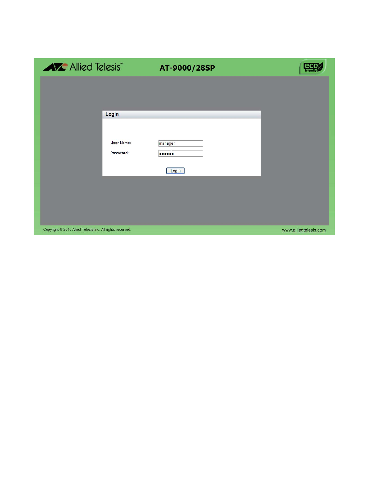
Figure 3. Login Page
9. Enter “manager” in the User Name field and “friend” in the Password
field. Then click the Login button.
22
Page 23
AlliedWare Plus Version 2.1.2 Management Software Web Browser User’s Guide
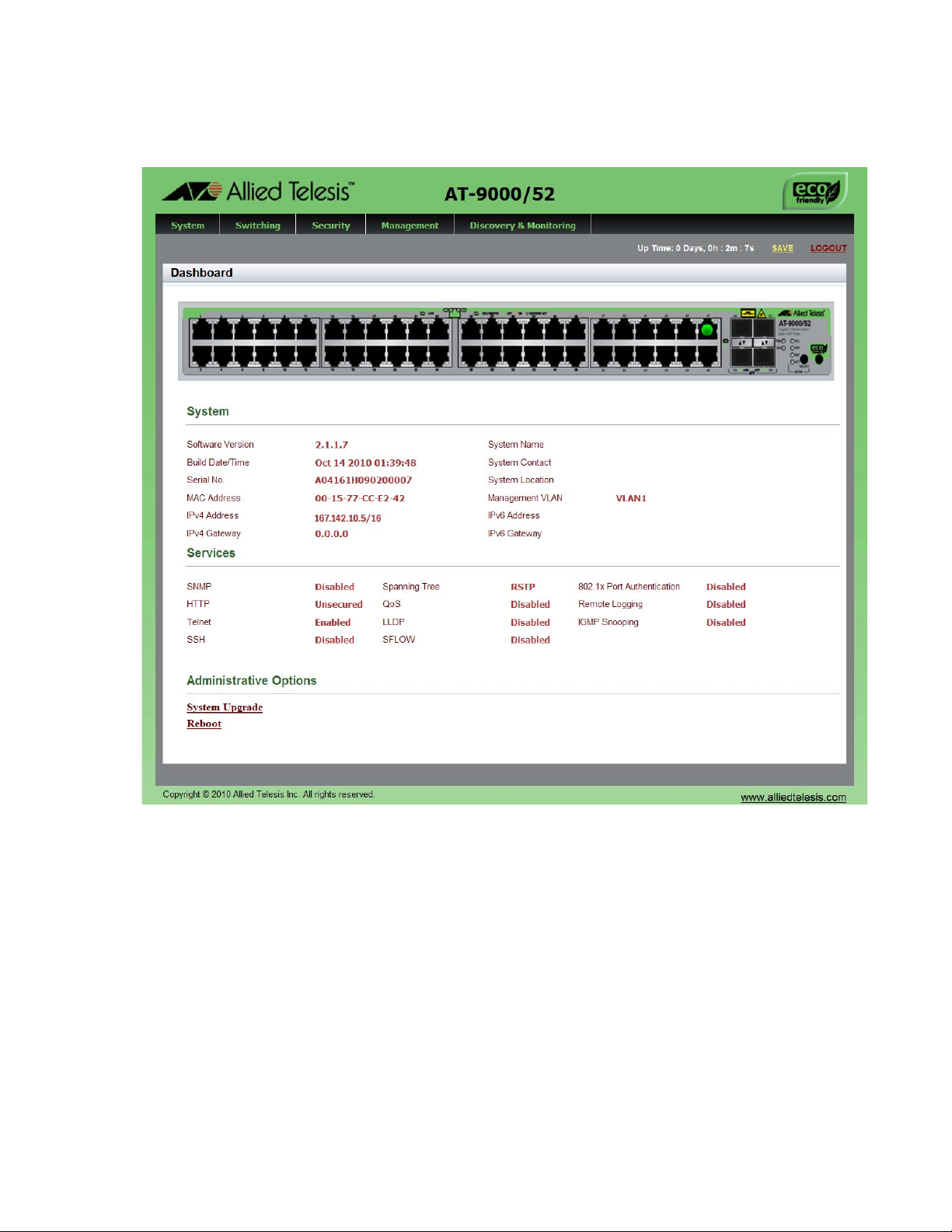
The Dashboard page is displayed. See Figure 4. The Dashboard p age
is the home page of the switch.
Figure 4. Dashboard Page
The following fields are displayed:
Up Time— Indicates the length of time since the switch was last
reset or power cycled in days, hours, minutes and seconds. This
field is located in the upper right-hand corner of the page.
The System section displays the following information:
Software Version— Lists the software version number of the
AlliedWare Plus software.
Build Date/Time— Lists the month, date, year and time (in the
hour:minute:second format) the software version was built.
Serial No.— Lists the unique serial number of the switch.
23
Page 24

Chapter 2: Starting a Management Session
Note
MAC Address— Specifies the MAC address of the switch.
IPv4 Address— Displays the IPv4 address and subnet mask of
the web interface. The IPv4 management address is assigned to
the switch. The address is specified in the following format:
xxx.xxx.xxx.xxx
Each x is a number from 0 to 255. There are four groups of
numbers that are separated by periods.
For IPv4 addresses, the subnet mask is a decimal number that
represents the number of bits, from left to right, that constitute the
network portion of the address. Here are some examples:
— The decimal mask 16 is equivalent to the mask 255.255.0.0.
— The decimal mask 24 is equivalent to the mask 255.255.255.0.
IPv4 Gateway— Displays the IPv4 address of the next hop of the
switch’s default route. The switch uses a default route when it must
communicate with a device that is not on the local IPv4 network.
System Name— Indicates the name of the switch. To configure
this field, see “Setting the Switch Information” on page 41.
System Contact— Indicates the contact person for the switch. To
configure this field, see “Setting the Switch Information” on
page 41.
System Location— Indicates the location of the switch. To
configure this field, see “Setting the Switch Information” on
page 41.
Management VLAN— Displays the management VLAN assigned
to the switch. The default VLAN is “VLAN1.”
IPv6 Address— Displays the IPv6 address and subnet mask of
the web interface. An IPv6 management address for the switch is
entered in the following format:
nnnn:nnnn:nnnn:nnnn:nnnn:nnnn:nnnn:nnnn
Where “n” is a hexadecimal digit from 0 to F. The eight groups of
digits are separated by colons. Groups where all four digits are ‘0’
can be omitted. Leading ‘0’s in groups can also be omitted.
For example, the following IPv6 addresses are equivalent:
12c4:421e:09a8:0000:0000:0000:00a4:1c50
12c4:421e:9a8::a4:1c50
24
Page 25

AlliedWare Plus Version 2.1.2 Management Software Web Browser User’s Guide
IPv6 Gateway— Displays the IPv6 address of the next hop of the
switch’s default route. The switch uses a default route when it must
communicate with a device that is not on the local IPv6 network.
The Services section displays the following information:
SNMP— Indicates the SNMP setting of the switch.
HTTP— Indicates the HTTP setting of the switch
Telnet— Indicates if Telnet is enabled or disabled on the switch.
SSH— Indicates if SSH is enabled or disabled on the switch.
Spanning Tree— Indicates if RSTP or STP is enabled on the
switch. The default setting is “RSTP.”
QoS— Indicates is QoS is enabled or disabled on the switch.
LLDP— Indicates if LLDP is enabled or disabled on the switch.
SFLOW— Indicates is sFlow is enabled or disabled on the switch.
802.1x Port Authentication— Indicates if 802.1x Port
Authentication is enabled or disabled on the switch.
Remote Logging— Indicates if the remote log is enabled or
disabled on the switch.
IGMP Snooping— Indicates if IGMP Snooping is enabled or
disabled on the switch.
The Administration Options section displays the following information:
System Upgrade— Select this field to upgrade your system
software. See “Upgrading the Software” on page 51.
Reboot— Select this field to reboot the switch. For instructions,
see “Rebooting a Switch” on page 50.
25
Page 26

Chapter 2: Starting a Management Session
Selecting items from a Web Page
To select a feature or parameter, place your cursor over the selection and
wait for it to turn orange. Then click on the selection.
26
Page 27

What to Configure First
Here are a few suggestions on what to configure during your web
management session on the switch. The initial management session must
be a local management session from the Console port on the switch. For
instructions on how to start a local management session, refer to “Starting
a Web Management Session” on page 20.
AlliedWare Plus Version 2.1.2 Management Software Web Browser User’s Guide
Assigning a Name
to the Switch
Adding a
Management IP
Address
The switch is easier to identify if you assign it a name. The switch’s name
is displayed on the Dashboard page. See Figure 4 on page 23. To change
the name of the switch, see “Setting the Switch Information” on page 41.
A name can be up to 39 alphanumeric characters. Spaces and quotation
marks are not permitted.
You must assign the switch a management IP address before you can
access the web interface. In addition, you may assign the switch both an
IPv4 and an IPv6 address. See Chapter 17, “Setting IPv4 and IPv6
Management” on page 187.
Here are the requirements:
The switch can have one management IPv4 address and one
management IPv6 address.
The switch can have one IPv4 default gateway and one IPv6 default
gateway.
A management IP address must be assigned to a VLAN on the switch.
It can be any VLAN, including the Default_VLAN which is “VLAN1.” For
background information on VLANs, refer to the AlliedWare Plus
Version 2.1.1 Command Line User’s Guide.
Setting System
Time
The network devices (such as, syslog servers, TFTP servers, etc.)
must be members of the same subnet as a management IP address or
have access to it through routers or other Layer 3 devices.
The switch must have a default gateway if the network devices are not
members of the same subnet as the management IP address. The
default gateway specifies the IP address of a router interface that
represents the first hop to the subnets or networks of the network
devices.
A default gateway address, if needed, must be a member of the same
subnet as a management IP address.
To set the system time either manually or with an NTP server, see “Setting
the System Date and Time” on page 32.
27
Page 28
Chapter 2: Starting a Management Session
Saving Your Changes
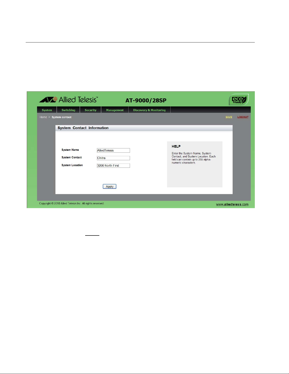
In the web interface, there are two ways to save your changes. After you
complete a procedure, click Apply as shown on the System Contact
Information page. See Figure 5. This saves the information to the running
configuration file. This information is not saved when you reboot the
switch.
28
Figure 5. System Contact Information Page
To permanently save your changes in the start-up configuration file, click
SAVE
at the top of the web page.
Page 29

AlliedWare Plus Version 2.1.2 Management Software Web Browser User’s Guide
Ending a Web Management Session
To end a web management session, select LOGOUT at the top o f the web
page. For an example, see the System Contact Inf ormation page in Figure
5 on page 28.
29
Page 30

Chapter 2: Starting a Management Session
30
Page 31

Chapter 3
Basic Switch Parameters
This chapter describes how to set up basic switch operations in the web
interface. See the following sections:
“Setting the System Date and Time” on page 32
“Setting a Telnet or SSH Server” on page 38
“Setting a Remote Log Server” on page 40
“Setting the Switch Information” on page 41
“Setting the Configuration File” on page 43
“Managing User Accounts” on page 45
“Rebooting a Switch” on page 50
“Upgrading the Software” on page 51
“Returning the AlliedWare Plus Management Software to the Factory
Default Values” on page 53
“Displaying System Information” on page 54
For additional information about basic port settings, see the following
chapters in the AlliedWare Plus Management Software Command Line
Interface User’s Guide:
Chapter 5: Basic Switch Management
Chapter 6: Basic Switch Management Commands
31
Page 32

Chapter 3: Basic Switch Parameters
Note
Note
Setting the System Date and Time
This procedure explains how to set the switch’s date and time. Setting the
date and time is important if you plan to view the events in the switch’s
event log or send the events to a syslog server. The correct date and time
are also important if the management software sends traps to a
management workstation or if you plan to create a self-signed SSL
certificate. Events, traps, and self-signed certificates should contain the
date and time of when they occurred or, in the case of certificates, when
they were created.
There are two ways to set the switch’s date and time. One method is to set
it manually. This method is not recommended because the date and time
are lost if you reboot the switch.
The second method uses the Simple Network Time Protocol (SNTP). The
AlliedWare Plus Management Software comes with the client version of
this protocol. You can configure the AlliedWare Plus software to obtain the
current date and time from an SNTP or Network Time Protocol (NTP)
server located on your network or the Internet.
SNTP is a reduced version of the NTP. However, the SNTP client software
in the AlliedWare Plus Management Software is interoperable with NTP
servers.
In order for the management software on the switch to communicate
with an SNTP or NTP server, there must be an interface on the local
subnet from where the switch is reaching the server. The switch
uses the IP address of the interface as its source address when
sending packets to the server.
The default system time on the switch is midnight, January 1, 2000.
Choose from the following procedures:
“Setting System Time Manually” on page 33
“Setting An SNTP or NTP Server” on page 35
32
Page 33

AlliedWare Plus Version 2.1.2 Management Software Web Browser User’s Guide
Setting System
Time Manually
To set the system time manually, do the following:
1. Select the System tab.
2. From the System tab, select System Settings.
The System Settings Tab is displayed in Figure 6.
Figure 6. System Settings Tab
3. Move the cursor to the right and select Time.
The System Time Settings page is displayed. See Figure 7 on page
34.
33
Page 34

Chapter 3: Basic Switch Parameters
Figure 7. System Time Settings Page
4. There are two ways to set the date and time manually. Use either step
4 or step 5. To type in the system date and time in the Date & Time
field, do the following:
a. Enter the time and date in the following format:
yyyy-dd-mm hh:mm:ss
b. Click Apply.
5. Select the calendar icon.
The Calendar page is displayed. See Figure 8 on page 35.
a. Use the arrows at the top of the Calendar to select the month and
year.
b. Click on the day of the month.
c. Set the time of day using the following format:
hh:mm:ss
34
Page 35

AlliedWare Plus Version 2.1.2 Management Software Web Browser User’s Guide
d. Close the Calendar page. See Figure 8.
Figure 8. Calendar Page
6. Enter the time at the bottom of the page in the hh:mm:ss format.
7. Click Apply
Setting An SNTP
or NTP Server
To configure SNTP or NTP server, do the following:
1. Select the System tab.
The System Settings Tab is displayed. See Figure 6 on page 33.
2. From the System tab, select System Settings.
3. Move the cursor to the right and select Time.
The System Time Settings Page page is displayed. For an example of
this page, see Figure 7 on page 34.
4. Select the Network Time Settings tab.
The Network Time Settings page is displayed. See Figure 9 on page
36.
35
Page 36

Chapter 3: Basic Switch Parameters
Figure 9. System Time Settings Page with Network Time Settings Tab
5. To configure the switch to obtain its date and time from an SNTP or
NTP server on your network or the Internet, configure the following
fields:
NTP Status— Enables or disables the SNTP client on the switch.
The default is disabled.
Server IP Address— S pe cifies the IP address of an SNTP server.
Enter either an IPv4 or IPv6 IP address.
The IPv4 format is: xxx.xxx.xxx.xxx where x is a decimal number
from 0 to 255.
The IPv6 format is: nnnn:nnnn:nnnn:nnnn:nnnn:nnnn:nnnn:nnnn
where n is a hexadecimal digit from 0 to F.
Time Zone— Specifies the time zone as a measurement of
Greenwich Mean Time (GMT) which is the default setting. Use the
pull-down menu to select the other time zones.
Daylight Savings Time (DST)— Enables or disables the system’s
adjustment for daylight savings time. The default is disabled.
36
Page 37

AlliedWare Plus Version 2.1.2 Management Software Web Browser User’s Guide
Note
Note
The switch does not set DST automatically. If the switch is in a
locale that uses DST, you must remember to enable this in April
when DST begins and disable it in October when DST ends. If the
switch is in a locale that does not use DST, this option shou ld be set
to disabled all the time.
If the local interface on the switch is obtaining its IP address and
subnet mask from a DHCP server, you can configure the server to
provide the interface with an IP address of an NTP or SNTP server.
If you configured the server to provide this address, then you do not
need to enter it here.
6. When you finish configuring the parameters, click Apply.
If you enabled the SNTP client, the switch immediately polls the SNTP
or NTP server for the current date and time. (When SNTP is enabled,
the switch automatically polls the server whenever a change is made
to any of the fields on this page.)
37
Page 38

Chapter 3: Basic Switch Parameters
Setting a Telnet or SSH Server
The AlliedWare Plus Web Browser interface allows you to configure the
switch as a Telnet or SSH server.
You can use the web browser interface to enable a Telnet server, but not
as a Telnet client. The Telnet client is only supported from local
management sessions of the switch. For information about how to use a
Telnet client, see the AlliedWare Plus Management Software Command
Line Interface User’s Guide. See Where to Find Management Software
Updates and Product Information on page 13.
To enable an SSH server in the web interface, you must first create an
encryption key in the CLI interface. Then you can enable the SSH server
in the web interface.
The procedures in this section allow you to configure the switch as a
Telnet or SSH server.
To assign the switch to a Telnet or SSH server, do the following:
1. From the home page, select the System tab.
The System Settings tab is displayed. See Figure 6 on page 33.
2. From the System Settings tab, select Services.
38
Page 39

AlliedWare Plus Version 2.1.2 Management Software Web Browser User’s Guide
Note
The System Services page is displayed. See Figure 10.
Figure 10. System Services Page
3. Configure the following parameters as necessary:
Telnet— Selecting this field enables a Telnet server on the switch.
To disable a Telnet server on the switch, unclick the box next to the
Telnet field. This parameter is optional.
SSH— Selecting this field enables an SSH server on the switch. To
disable an SSH server on the switch, unclick the box next to the
SSH filed. This parameter is optional.
Both the Remote Log and Server IP Address fields are used only to
set a remote log server. For information on these fields, see “Setting
a Remote Log Server” on page 40.
Remote Log— This field is only used for the remote log server.
Server IP Address— This field is only used for the remote log
server.
4. Click Apply.
5. Click S
AVE to save your changes on the switch.
39
Page 40

Chapter 3: Basic Switch Parameters
Setting a Remote Log Server
You can use the AlliedWare Plus Web browser interface to assign the
switch to a remote log server which is part of the Syslog feature. However,
you must use the CLI to view or clear the event log. For information about
the CLI, see the SysLog chapters in the AlliedWare Plus Management
Software Command Line Interface User’s Guide.
To activate remote logging on the switch, do the following:
1. Select the System tab.
The System Settings tab is displayed. See Figure 6 on page 33.
2. From the System Settings tab, select Services.
The System Services page is displayed. See Figure 10 on page 39.
3. Configure the following parameters as necessary:
Remote Log— Enables the switch to send status and error
messages to a remote log server. This parameter is optional.
Server IP Address— Specifies the IP address of the remote log
server. This field is mandatory if you selected the Remote Log field
above. You can enter the IP address in the IPv4 format:
xxx.xxx.xxx.xxx.
where each x is a decimal number from 0 to 255. The numbers are
separated by periods.
4. Click Apply.
5. Click S
AVE to save your changes on the switch.
40
Page 41

Setting the Switch Information
This procedure allows you to set information about the switch such as a
switch name, contact, and location. Assigning a name to the switch helps
you identify your switches when you manage them and help you to avoid
performing a configuration procedure on the wrong switch.
To assign a name, location, and contact to a switch, perform the following
procedure:
1. From the home page, select the System tab.
2. From the System tab, select System Settings.
The System Setting tab is displayed. See Figure 6 on page 33.
3. Move the cursor to the right and select Contact Information.
The System Contact Information page is displayed. See Figure 11.
AlliedWare Plus Version 2.1.2 Management Software Web Browser User’s Guide
Figure 11. System Contact Information Page
41
Page 42

Chapter 3: Basic Switch Parameters
Change the following parameters as necessary:
System Name— Specifies a name for the switch (for example,
Sales Ethernet switch). The name is displayed only on the
Dashboard page. The name can be from 1 to 39 characters in
length. It can include spaces and special characters, such as
dashes and asterisks. By default, there is no system name. This
parameter is optional.
System Contact — Specifies the name of the network
administrator responsible for managing the switch. The name can
be from 1 to 20 characters. It can include spaces and special
characters, such as dashes and asterisks. The default is no name.
This parameter is optional.
System Location— Specifies the location of the switch, (for
example, 4th Floor - room 402B). The location can be from 1 to 20
characters. The location can include spaces and special
characters, such as dashes and asterisks. The default is no
location. This parameter is optional.
4. Click Apply.
5. Click S
AVE to activate your changes on the switch.
42
Page 43

Setting the Configuration File
Within the web browser interface, you can upload a configuration file on to
the switch, download a configuration file from the switch, or delete a
configuration file. In addition, you can save your changes to the
current configuration file. However, to create a new configuration file, you
need to access the switch through the CLI.
The file that you select in this procedure is file that the switch uses the next
time you reboot the switch.
See the following procedures:
“Displaying and Setting the Active Configuration File” on page 43
“Uploading a Configuration File” on page 44
AlliedWare Plus Version 2.1.2 Management Software Web Browser User’s Guide
Displaying and
Setting the Active
Configuration
File
The file you select in this procedure is the active configuration file after you
reboot the switch.
To select the active configuration file, do the following:
1. From the home page, click the System tab.
The System Settings tab is displayed. See Figure 6 on page 33.
2. From the System tab, select Configuration Files from the pull-down
menu.
For an example of the Configuration Files page, see Figure 12.
Figure 12. Configuration Files Page
43
Page 44

Chapter 3: Basic Switch Parameters
The following fields are displayed:
Startup Config— Displays the name of the active boot
configuration file, which for the switch in the example is “boot.cfg.”
File Name— Indicates the name of the configuration files.
File Size— Lists the file size in bytes.
Last Modify— Indicates the date the configuration file was last
modified. The format is year, month, date.
3. Use the pull-down menu to select the active configuration file. Then
click Apply.
The file you select is the active configuration file after you reboot the
switch.
Uploading a
Configuration
File
4. Click SAVE
.
To upload a configuration file onto the switch, do the following:
1. From the home page, click the System tab.
For an example of the System tab, see Figure 11 on page 41.
2. From the System tab, select Configuration Files.
For an example of the Configuration Files page, See Figure 12 on
page 43.
3. Click Upload.
The File Upload page is displayed. See Figure 13.
44
Figure 13. File Upload Page
4. Click Browse to select a file to upload onto the switch.
5. Select the file and then click Upload.
Page 45

AlliedWare Plus Version 2.1.2 Management Software Web Browser User’s Guide
Managing User Accounts
The procedures in this section describe how to create user accounts as
well as change passwords and privileges. There is also a procedure that
describes how to delete a user account. See the following:
“Adding a User” on page 45
“Changing a User Password” on page 46
“Changing the User Privilege” on page 48
“Deleting a User” on page 49
Adding a User To add a user, do the following:
1. From the home page, click the System tab.
The System Settings tab is displayed, see Figure 6 on page 33.
2. From the System Settings tab, select User Management.
For an example of the User Management page, see Figure 14.
Figure 14. User Management Page
45
Page 46

Chapter 3: Basic Switch Parameters
Note
3. Enter a name in the User Name field.
This field specifies the log on name for the new account. The name is
case sensitive and can contain up to fifteen alphanumeric characters.
Spaces and special characters are not allowed.
4. Enter a password in the Password field.
This specifies the password for the new management account. You
can enter the password in plaintext or encrypted. A plainte xt password
can consist of up to 16 alphanumeric characters and is case-sensitive.
Spaces and special characters are not allowed. To enter an already
encrypted password, precede it with the number “8.”
A plaintext password that begins with the number “8” is not
encrypted.
5. Use the pull-down menu in the Privilege field to select a user privilege
level. Choose from the following:
Changing a User
Password
Level 15: Management accounts with a user level of 15 have
unrestricted access to the software. This is the default setting.
Level 1: Management accounts with a user level of 1 have
restricted access to the software.
6. Click Add User
7. Click SAVE
.
.
To change a user password, do the following:
1. From the home page, click the System tab.
The System Settings Tab is displayed. See Figure 6 on page 33.
2. From the System Settings tab, select User Management.
The User Management page is displayed. See Figure 14 on page 45.
3. From the User Management page, select the Change Password tab.
The User Management page with the Change Password tab is
displayed. See Figure 15 on page 47.
46
Page 47

AlliedWare Plus Version 2.1.2 Management Software Web Browser User’s Guide
Note
Figure 15. User Management Page with Change Password Tab
4. Use the pull-down menu next to the User Name field to select the user
name.
The user name must already exist.
5. Enter a new password in the New Password field.
You can enter the password in plaintext or encrypted. A plaintext
password can consist of up to 16 alphanumeric characters and is
case-sensitive. Spaces and special characters are not allowed. To
enter an already encrypted password, precede it with the number “8.”
A plaintext password that begins with the number “8” is not
encrypted.
6. Re-enter the new password in the Confirm New Password field.
7. Click Set Password
.
8. Click SAVE
.
47
Page 48

Chapter 3: Basic Switch Parameters
Changing the
User Privilege
To change a privilege of a user, do the following:
1. From the home page, click the System tab.
The System Settings Tab is displayed. See Figure 6 on page 33.
2. From the System Settings tab, select User Management.
The User Management page is displayed. See Figure 14 on page 45.
3. From the User Management page, select the Change Privilege tab.
The User Management page with the Change Privilege tab is
displayed. See Figure 16.
48
Figure 16. User Management Page with Change Privilege Tab
4. Use the pull-down menu next to the User Name field to select a user.
5. Use the pull-down menu next the New Privilege field to select a user
privilege level. Choose from the following:
Level 15: Management accounts with a user level of 15 have
unrestricted access to the software. This is the default setting.
Page 49

AlliedWare Plus Version 2.1.2 Management Software Web Browser User’s Guide
Level 1: Management accounts with a user level of 1 have
restricted access to the switch.
6. Click Set Privilege.
7. Click SAVE
to save your changes to the start-up configuration file.
Deleting a User To delete a user name from the switch, do the following:
1. From the home page, click the System tab.
The System Settings Tab is displayed. See Figure 6 on page 33.
2. From the System Settings tab, select User Management.
The User Management page is displayed. See Figure 14 on page 45.
3. From the User Management page, select the Delete User tab.
The User Management page with the Delete User tab is displayed.
See Figure 17.
Figure 17. User Management Page with Delete User Tab
4. Use the pull-down menu to select a user.
5. Click Delete User.
6. Click SAVE
.
49
Page 50

Chapter 3: Basic Switch Parameters
Note
Note
Rebooting a Switch
Resetting the switch ends your web browser management session. To
continue managing the switch, you must login again.
All unsaved changes are discarded when you reset a switch. To
save your changes, click SAVE on the home page.
To reboot a switch, perform the following procedure:
1. Select the System Tab.
The System Settings Tab is displayed. See Figure 6 on page 33.
2. From the System Settings tab, select Dashboard.
The Dashboard Page is displayed. See Figure 4 on page 23.
3. Select Reboot
A confirmation prompt is displayed that indicates that the connection to
the web is lost during a reboot.
4. Click OK to reset the switch or Cancel to cancel the procedure.
The switch does not forward packets while it initializes the
AlliedWare Plus software and loads its active configuration file. This
process takes between 20 seconds to 2 minutes to complete,
depending on the number and types of commands in the
configuration file.
at the bottom of the page.
50
Page 51

Upgrading the Software
Note
You can obtain the latest version of the AlliedWare Plus software from the
Allied Telesis web site. You must have access to a TFTP server from your
PC to upgrade the AlliedWare Plus software on your switch. Allied Telesis
does not include this application with the software. The upgrade process
takes approximately three minutes.
Upgrading the system software on the switch ends your current web
browser management session. To continue managing the switch, you
must login again.
All unsaved changes are discarded when you upgrade the software
on a switch. To save your changes, click SAVE.
To upgrade the AlliedWare Plus software, perform the following
procedure:
AlliedWare Plus Version 2.1.2 Management Software Web Browser User’s Guide
1. Open your TFTP server software and provide it with the IP address of
the your PC.
2. Select the System Tab.
The System Settings Tab is displayed. See Figure 6 on page 33.
3. From the System Settings tab, select Dashboard.
The Dashboard Page is displayed. See Figure 4 on page 23.
4. Select System Upgrade
The System Upgrade page is displayed. See Figure 18 on page 52.
at the bottom of the page.
51
Page 52

Chapter 3: Basic Switch Parameters
Figure 18. System Upgrade Page
5. Click Browse to select an image file.
6. Click Open to select a file.
7. Click Start Upgrade to begin the software upgrade or Cancel to
cancel the procedure.
52
Page 53

AlliedWare Plus Version 2.1.2 Management Software Web Browser User’s Guide
Returning the AlliedWare Plus Management Software to the Factory Default Values
To reset the AlliedWare Plus Management Software parameters to their
default values, you must use the Command Line Interface. You cannot
reset the management software to its factory settings in the web interface.
For instructions, see Chapter 5: Basic Switch Management in the
AlliedWare Plus Management Software Command Line User’s Guide on
our web site. To locate manuals online, see Where to Find Management
Software Updates and Product Information on page 13.
53
Page 54

Chapter 3: Basic Switch Parameters
Note
Displaying System Information
To view basic information about the switch, do the following:
1. Select the System Tab.
The Dashboard Page is displayed. See Figure 4 on page 23.
The following fields are displayed:
Up Time— Indicates the length of time since the switch was last
reset or power cycled in days, hours, minutes and seconds.
The System section displays the following information:
Software Version— Lists the software version number of the
AlliedWare Plus software.
Build Date/Time— Lists the month, date, year and time (in the
hour:minute:second format) the software version was built.
Serial No.— Lists the unique serial number of the switch.
MAC Address— Specifies the MAC address of the switch.
IPv4 Address— Displays the IPv4 address and subnet mask of
the web interface. The IPv4 management address to assigned the
switch. The address is specified in the following format:
xxx.xxx.xxx.xxx
Each “x” is a decimal number from 0 to 255. The numbers must be
separated by periods.
For both the IPv4 and IPv6 addresses, the subnet mask is a decimal
number that represents the number of bits, from left to right, that
constitute the network portion of the address. Here are some
examples:
— The decimal mask 16 is equivalent to the mask 255.255.0.0.
— The decimal mask 24 is equivalent to the mask 255.255.255.0
— The IPv6 decimal mask 24 is equivalent to the mask
FFFF:FF00::0.
IPv4 Gateway— Displays the IPv4 address of the next hop of the
switch’s default route. The switch uses a default route when it
receives a network packet for routing, but it cannot find an
available route in the routing table.
System Name— Indicates the name of the switch. To configure
this field, see “Setting the Switch Information” on page 41.
54
Page 55

AlliedWare Plus Version 2.1.2 Management Software Web Browser User’s Guide
System Contact— Indicates the contact person for the switch. To
configure this field, see “Setting the Switch Information” on
page 41.
System Location— Indicates the location of the switch. To
configure this field, see “Setting the Switch Information” on
page 41.
Management VLAN— Displays the management VLAN assigned
to the switch. The default VLAN is “VLAN1.”
IPv6 Gateway— Displays the IPv6 address of the next hop of the
switch’s default route. The switch uses a default route when it
receives a network packet for routing, but it cannot find an
available route in the routing table.
IPv6 Address— Displays the IPv6 address and subnet mask of
the web interface. An IPv6 management address for the switch is
entered in the following format:
nnnn:nnnn:nnnn:nnnn:nnnn:nnnn:nnnn:nnnn
Where “n” is a hexadecimal digit from 0 to F. The eight groups of
digits are separated by colons. Groups where all four digits are ‘0’
can be omitted. Leading ‘0’s in groups can also be omitted. For
example, the following IPv6 addresses are equivalent:
12c4:421e:09a8:0000:0000:0000:00a4:1c50
12c4:421e:9a8::a4:1c50
The Services section displays the following information:
SNMP— Indicates the SNMP setting of the switch.
HTTP— Indicates the HTTP setting of the switch
Telnet— Indicates if Telnet is enabled or disabled on the switch.
SSH— Indicates if SSH is enabled or disabled on the switch.
Spanning Tree— Indicates if RSTP or STP is enabled on the
switch. The default setting is RSTP.
QoS— Indicates is QoS is enabled or disabled on the switch.
LLDP— Indicates if LLDP is enabled or disabled on the switch.
SFLOW— Indicates is sFlow is enabled or disabled on the switch.
802.1x Port Authentication— Indicates if 802.1x Port
Authentication is enabled or disabled on the switch.
Remote Logging— Indicates if the remote log is enabled or
disabled on the switch.
IGMP Snooping— Indicates if IGMP Snooping is enabled or
disabled on the switch.
55
Page 56

Chapter 3: Basic Switch Parameters
The Administration Options section displays the following information:
System Upgrade— Select this field to upgrade your system
software. See “Upgrading the Software” on page 51.
Reboot— Select this field to reboot the switch. For instructions,
see “Rebooting a Switch” on page 50.
56
Page 57

Chapter 4
Setting Port Parameters
This chapter describes how to display and modify the port settings such as
back pressure and flow control. In addition, it provides procedures to
display and modify storm control settings.
This chapter contains the following sections:
“Displaying the Port Parameters” on page 58
“Changing the Port Settings” on page 62
“Displaying the Storm Control Settings” on page 66
“Modifying the Storm Control Settings” on page 68
For additional information about the port parameters and the storm control
feature, see the following chapters in the AlliedWare Plus Management
Software Command Line Interface User’s Guide:
Chapter 7: Port Parameters
Chapter 8: Port Parameter Commands
57
Page 58

Chapter 4: Setting Port Parameters
Displaying the Port Parameters
The port numbering system in the AlliedWare Plus web browser interface
is different from the port numbering system in the CLI. For an example of
the port numbering equivalents for the first five ports, see Table 1.
Table 1. Port Numbering the Web versus the CLI
Web Port Numbering CLI Port Numbering
port 1 port 1.0.1
port 2 port 1.0.2
port 3 port 1.0.3
port 4 port 1.0.4
port 5 port 1.0.5
port 5 port 1.0.6
port 7 port 1.0.7
port 8 port 1.0.8
Within the display, there is no differentiation between ports 25 through 28
and ports 25R through 28R. In the web interface, if you want to see if port
25 is connected versus port 25R, go to the home page and look at the
illustration of the switch. For an example of the home page, see Figure 4
on page 23.
To display the settings for all of the switch ports, do the following:
1. Select the Switching tab.
The Switching tab is displayed. See Figure 19.
58
Figure 19. Switching Tab with Port Tab
Page 59

AlliedWare Plus Version 2.1.2 Management Software Web Browser User’s Guide
2. From the Switching tab, select Port.
The Port tab expands to the right.
3. From the Port tab, select Port Configuration.
The Port Configuration page is displayed. See Figure 20.
Figure 20. Port Configuration Page
59
Page 60

Chapter 4: Setting Port Parameters
Note
4. The following fields are displayed:
Port— Indicates the port number.
Type— Specifies the if the port is fiber, indicated by 1000-FX, or
copper, indicated by 100-FX.
Status— Indicates if the port is enabled or disabled. The default
setting is “Enabled.” Disabling ports turns off their receivers and
transmitters so that they cannot forward traffic.
Link— Indicates the port has successfully connected to a port on
another switch or unit.
Negotiation— Indicates Autonegotiation. By default,
Autonegotiation is enabled.
Speed— Specifies the speed of the port. The default setting is
“1000-FX” for 1000Mbps. The other possible options are “10” for
10Mbps and “100” for 100Mbps.
Duplex— Indicates the duplex mode of the twisted pair ports or
Auto Negotiation. The three settings are half, full, and Auto
Negotiation.
Polarity— Indicates the port’s wiring configuration is MDI (medium
dependent interface) or MDI-X (medium dependent interface
crossover). This setting only applies to a twisted pair port that is
operating at 10 or 100 Mbps.
You can enable or disable backpressure on ports where you
disabled Auto-Negotiation and set the speeds and duplex modes
manually to 10 or 100 Mbps in half-duplex mode.
Back Pressure— Indicates if back pressure is enabled or disabled
on a port. Backpressure is used by ports during periods of packet
congestion to temporarily stop their network counterparts from
transmitting more packets. This prevents a buffer overrun and the
subsequent loss and retransmission of network packets. A port
initiates backpressure by transmitting on the shared link to cause a
data collision, which causes its link partner to cease transmission.
The default setting is “Disabled.”
Back Pressure Limit— Indicates the threshold level for back
pressure on a port. Specifies the number of cells for back
pressure. The default value is 7935 cells.
Flow Control— Indicates if flow control (send and receive) is
enabled or disabled on a port. When flow control is enabled, a port
sends pause packets when it reaches the point of packet
congestion. Also, the port stops transmitting packets when it
receives pause packets from its local or remote counterpart. When
flow control is disabled, the port sends pause packet regardless of
60
Page 61

AlliedWare Plus Version 2.1.2 Management Software Web Browser User’s Guide
packet congestion. In addition the port continues transmitting
packets when it receives pause packets from its local or remote
counterpart. The default is “Disabled.”
Flow Control Limit— Indicates the threshold level for flow control
on a port. The default value is 7935.
61
Page 62

Chapter 4: Setting Port Parameters
Changing the Port Settings
You can change the settings of one port at a time. Use the following
procedure to change the port settings or reset a port to its default value,
To change the port settings, do the following:
1. Select the Switching tab.
The Switching tab is displayed. See Figure 19 on page 58.
2. From the Switching tab, select Port.
The Port tab expands to the right.
3. From the Port tab, select Port Configuration.
The Port Configuration page is displayed. See Figure 20 on page 59.
4. Click Edit
The Port Configuration Modify page is displayed. See Figure 21 on
page 63.
next to the port that you want to modify.
62
Page 63

AlliedWare Plus Version 2.1.2 Management Software Web Browser User’s Guide
Figure 21. Port Configuration Modify Page
5. Configure the following parameters as needed:
Port— Indicates the port number.
Port Type— Indicates the type of port, fiber or copper. You cannot
modify this field.
Status— Indicates if the port is enabled or disabled. Choose
between “Enabled” or “Disabled.” The default setting is “Enabled.”
Disabling ports turns off their receivers and transmitters so that
they cannot forward traffic. You may want to disable a port if there
is a problem with a cable or network device.
Negotiation— Indicates the state of Auto Negotiation on a port.
Select “Auto” to enable Auto Negotiation on a port or “Manual” to
disable Auto Negotiation. The default setting is Auto. When the
setting for this field is “Auto,” the Speed and Duplex fields change
63
Page 64

Chapter 4: Setting Port Parameters
from white to brown and you cannot select them. To change the
Speed and Duplex Mode fields, change the Negotiation setting to
“Manual.”
Speed— Indicates the port speed. Select 10mb, 100mb, or
1000mb.
Duplex Mode— Sets the set the duplex modes of the twisted pair
ports or activates Auto-Negotiation manually. The settings are half,
full, or Auto Negotiation. Ports operating in half-duplex mode can
either receive or transmit packets, but not both at the same time.
Ports operating in full-duplex can both send and receive packets,
simultaneously.
Polarity— Sets the wiring configuration of the twisted pair ports
when they are operating at 10 or 100 Mbps, in either half- or fullduplex mode.
A twisted pair port that is operating at 10 or 100 Mbps can have
one of two wiring configurations. The configurations are known as
MDI and MDI-X. To forward traffic, a port on the switch and a port
on a network device must have different settings. For instance, the
wiring configuration of a switch port has to be MDI if the wiring
configuration on a port on a network device is MDIX.
To set this parameter on a port, you must set the speed and duplex
mode manually. A port that is using Auto-Negotiation sets its wiring
configuration automatically using auto-MDI/MDIX.
Back Pressure Status— Activates or deactivates back pressure
on the ports. Use this field to enable or disable back pressure on
ports that are operating at 10 or 100 Mbps in half-duplex mode.
Back pressure is used by ports during periods of packet
congestion to temporarily stop their network counterparts from
transmitting more packets. This prevents a buffer overrun and the
subsequent loss and retransmission of network packets. A port
initiates back pressure by transmitting on the shared link to cause
a data collision, which causes its link partner to cease
transmission.
To set back pressure on a port, you must configure the speed and
duplex mode manually. You cannot set back pressure on a port
that is using Auto-Negotiation.
Back Pressure Limit (1 - 7935)— Indicates a threshold level for
back pressure on a port. Specifies the number of cells for back
pressure. A cell represents 128 bytes. The range is 1 to 7935 cells.
The default value is 7935 cells.
Flow Control Status— Enables or disables the flow control
feature. By default, flow control is disabled on a port.
64
Page 65

AlliedWare Plus Version 2.1.2 Management Software Web Browser User’s Guide
Flow Control Limit (1 - 7935)— Indicates the threshold levels for
flow control on the ports. Specifies the number of cells for flow
control. A cell represents 128 bytes. The range is 1 to 7935 cells.
The default value is 7935 cells.
6. To set the port to the default port value, click Default. Otherwise skip
this step.
7. Click Apply.
8. Click SAVE
.
65
Page 66

Chapter 4: Setting Port Parameters
Displaying the Storm Control Settings
To display the storm control settings, do the following:
1. Select the Switching tab.
The Switching tab is displayed. See Figure 19 on page 58.
2. From the Switching tab, select Port.
The Port tab expands to the right.
3. From the Port tab, select Storm Control.
The Storm Control List page is displayed. See Figure 22.
66
Figure 22. Storm Control List Page
The following fields are displayed:
Port Id— Indicates the port number.
Broadcast— Indicates Broadcast packets are received, indicated
by “ON,” or not received, indicated by “OFF,” by the port. By
default, Broadcast packets are not received by a port.
Broadcast Level— Specifies the maximum number of ingress
packets per second of broadcast packets the port will forward. The
range is 0 to 33,554,431 packets. The default is 33,554,431
packets.
Multicast— Indicates Multicast packets are “ON” or “OFF” on the
port. By default, Multicast packets are not received by a port.
Page 67

AlliedWare Plus Version 2.1.2 Management Software Web Browser User’s Guide
Multicast Level— Specifies the maximum number of ingress
packets per second of multicast packets the port will forward. The
range is 0 to 33,554,431 packets. The default is 33,554,431
packets.
Dlf— Indicates unknown unicast packets are “ON” or “OFF” on the
port. By default, the setting is “ON” indicating that unknown unicast
packets are received by a port.
Dlf Level— Specifies the maximum number of ingress packets per
second of unknown unicast packets the port forwards. The range is
0 to 33,554,431 packets. The default is 33,554,431 packets.
67
Page 68

Chapter 4: Setting Port Parameters
Modifying the Storm Control Settings
To modify the storm control settings, do the following:
1. Select the Switching tab.
The Switching tab is displayed. See Figure 19 on page 58.
2. From the Switching tab, select Port.
The Port tab expands to the right.
3. From the Port tab, select Storm Control.
The Storm Control List page is displayed. See Figure 20 on page 59.
4. Click Edit
The Storm Control Settings page is displayed. See Figure 23.
on the port that you want to modify.
68
Figure 23. Storm Control Settings Page
Page 69

AlliedWare Plus Version 2.1.2 Management Software Web Browser User’s Guide
5. Change the following fields as needed:
Port Number— Indicates the port number.
Broadcast— Indicates Broadcast packets are received, indicated
by “ON,” or not received, indicated by “OFF,” by the port. By
default, Broadcast packets are not received by a port.
Broadcast Level— Specifies the maximum number of ingress
packets per second of broadcast packets the port will forward. The
range is 0 to 33,554,431 packets. The default is 33,554,431
packets.
Multicast— Indicates Multicast packets are “ON” or “OFF” on the
port. By default, this field is set to “OFF” which indicates Multicast
packets are not received by a port.
Multicast Level— Specifies the maximum number of ingress
packets per second of multicast packets the port forwards. The
range is 0 to 33,554,431 packets. The default is 33,554,431
packets.
DLF— Indicates unknown unicast packets are “ON” or “OFF” on
the port. By default, the setting is “ON” indicating that unknown
unicast packets are received by a port.
DLF Level— Specifies the maximum number of ingress packets
per second of unknown unicast packets the port forwards. The
range is 0 to 33,554,431 packets. The default is 33,554,431
packets.
6. Click Apply.
7. Click SAVE
.
69
Page 70

Chapter 4: Setting Port Parameters
70
Page 71

Chapter 5
Setting Port Statistics
This chapter describes how to display and clear port statistics. Within the
AlliedWare Plus software, you can display and clear transmit, receive, and
interface port statistics.
This chapter contains the following topics:
“Displaying Port Statistics” on page 72
“Clearing Port Statistics” on page 79
For additional information about port statistics, see the following chapters
in the AlliedWare Plus Management Software Command Line Interface
User’s Guide:
Chapter 7: Port Parameters
Chapter 8: Port Parameter Commands
71
Page 72

Chapter 5: Setting Port Statistics
Displaying Port Statistics
You can display several types of port statistics. See the following sections:
“Displaying Transmit and Receive Port Statistics” on page 72
“Displaying the Receive Statistics” on page 73
“Displaying Transmit Statistics” on page 75
“Displaying Interface Statistics” on page 77
Displaying
Transmit and
Receive Port
Statistics
To display the transmit and receive statistics for all of the switch ports, do
the following:
1. Select the Switching tab.
The Switching tab is displayed. See Figure 19 on page 58.
2. From the Switching tab, select Port.
3. Move the cursor to the right and select Statistics.
The Port St atistics page is displayed with the Tx + Rx tab automa tically
selected. See Figure 24.
72
Figure 24. Port Statistics Page with Tx + Rx Tab
Page 73

AlliedWare Plus Version 2.1.2 Management Software Web Browser User’s Guide
The following fields are displayed:
Port— Indicates the port number.
0-64 Byte Frames— The number of frames transmitted by the port
that contain 0 to 64 bytes.
65-127 Byte Frames— The number of frames transmitted by the
port that contain 65 to 127 bytes.
128-255 Byte Frames— The number of frames transmitted by the
port that contain 128 to 255 bytes.
256-511 Byte Frames— The number of frames transmitted by the
port that contain 256 to 511 bytes.
512-1023 Byte Frames—The number of frames transmitted by the
port that contain 512 to 1023 bytes.
1024-1518 Byte Frames— The number of frames transmitted by
the port that contain 1024 to 1518 bytes.
1519-1522 Byte Frames— The number of frames transmitted by
the port that contain 1519 to 1522 bytes.
Displaying the
Receive Statistics
To display the statistics on the Receive Statistics tab, do the following:
1. Select the Switching tab.
The Switching tab is displayed. See Figure 19 on page 58.
2. From the Switching tab, select Port.
3. Move the cursor to the right and select Statistics.
The Port Statistics page with the Tx + Rx tab selected is displayed.
See Figure 24 on page 72.
4. Click on the Receive Tab.
The Port Statistics with the Receive tab selected is displayed. See
Figure 25 on page 74.
73
Page 74

Chapter 5: Setting Port Statistics
Figure 25. Port Statistics with the Receive Tab
The following fields are displayed:
Port— Indicates the port number.
Total Bytes— Indicates the number of received bytes.
Total Frames— Indicates the number of received frames.
Total Error Frames— Indicates the total number of received
frames with errors.
Multicast Frames— Indicates the number of received multicast
frames.
Broadcast Frames— Indicates the number of received broadcast
frames.
CRC Frame Errors— Indicates the number of frames with a cyclic
redundancy check (CRC) error but with the proper length (64 1518 bytes) received by the port.
FSC Frame Errors— Indicates the number of ingress frames that
had frame check sequence (FCS) errors.
Pause Frames— Indicates the number of received flow control
pause frames.
74
Oversize Frames— Indicates the number of received frames that
exceeded the maximum size as specified by IEEE 802.3 (1518
bytes including the CRC).
Page 75

AlliedWare Plus Version 2.1.2 Management Software Web Browser User’s Guide
Note
Fragmented Frames— Indicates the number of undersized
frames, frames with alignment errors, and frames with frame check
sequence (FCS) errors (CRC errors).
Jabber Frames— Indicates the number of occurrences of
corrupted data or useless signals the port has encountered.
The following fields are not displayed in Figure 25 on page 74.
Undersize Frames— Indicates the number of received frames that
were less than the minimum length as specified by IEEE 802.3 (64
bytes including the CRC).
Dropped Frames— Indicates the number of frames successfully
received and buffered by the port, but discarded and not
forwarded.
MTU Exceed Discarded Frames— Indicates the number of
received frames with an MTU that exceeds the MTU of the switch.
These frames are discarded.
Displaying
Transmit
Statistics
MAC Error Frames— Indicates the number of Receive Error
events seen by the receive side of the MAC.
To display the statistics on the Transmit Statistics tab, do the following:
1. Select the Switching tab.
The Switching tab is displayed. See Figure 19 on page 58.
2. From the Switching tab, select Port.
3. Move the cursor to the right and select Statistics.
The Port Statistics page with the Tx + Rx tab selected is displayed.
See Figure 24 on page 72.
4. Click the Transmit tab.
75
Page 76

Chapter 5: Setting Port Statistics
The Port Statistics with the Transmit tab selected is displayed. See
Figure 26.
Figure 26. Port Statistics with the Transmit Tab
The following fields are displayed:
Port— Indicates the port number.
Total Bytes— Indicates the number of transmitted bytes.
Total Frames— Indicates the number of transmitted frames.
Total Error Frames— Indicates the number of transmitted frames
with errors.
Multicast Frames— Indicates the number of transmitted multicast
frames.
Broadcast Frames— Indicates the number of transmitted
broadcast frames.
Pause Frames Sent— Indicates the number of transmitted flow
control pause frames.
Deferred— Indicates the number of egress frames that the port
could not immediately transmit.
Single Collision— Indicates the number of frames that were
transmitted after at least one collision.
Multi Collision— Indicates the number of frames that were
transmitted after more than one collision.
76
Late Collision— Indicates the number of late collisions.
Excessive Collision— Indicates the number of excessive
collisions.
Page 77

AlliedWare Plus Version 2.1.2 Management Software Web Browser User’s Guide
Total Collision Frames— Indicates the total number of collisions
on the port.
MAC Error Frames— Indicates the number of frames not
transmitted correctly or dropped due to an internal MAC transmit
error.
Displaying
Interface
Statistics
To display the interface statistics, do the following:
1. Select the Switching tab.
The Switching tab is displayed. See Figure 19 on page 58.
2. From the Switching tab, select Port.
3. Move the cursor to the right and select Statistics.
The Port Statistics page with the Tx + Rx tab selected is displayed.
See Figure 24 on page 72.
4. Click the Interface tab.
The Port Statistics Page with the Interface tab selected is displayed.
See Figure 27.
Figure 27. Port Statistics Page with Interface Tab
The following fields are displayed:
Port— Indicates the port number.
Rx Unicast Packets— Indicates the number of ingress unicast
packets.
77
Page 78

Chapter 5: Setting Port Statistics
Rx Discard Packets— Indicates the number of ingress packets
that were discarded prior to transmission because of an error.
Rx IP Header Error Packets— Indicates the number of ingress
packets that were discarded because of a hardware error.
Tx Unicast Packets— Indicates the number of egress unicast
packets.
Tx Discard Packets— Indicates the number of egress packets
that were discarded prior to transmission because of an error.
Tx Error Packets— Indicates the number of egress error packet s.
78
Page 79

Clearing Port Statistics
To clear the statistics for a port, do the following:
1. Select the Switching tab.
The Switching tab is displayed. See Figure 19 on page 58.
2. From the Switching tab, select Port.
3. Move the cursor to the right and select Statistics.
The Port Statistics Page with Tx + Rx tab selected is displayed. See
Figure 24 on page 72.
4. Select the desired Port Statistics tab. Choose from the following:
Tx+Rx— Displays the transmit and receive statistics. (This is the
AlliedWare Plus Version 2.1.2 Management Software Web Browser User’s Guide
default.)
Receive— Displays the receive statistics.
Transmit— Displays the transmit statistics.
Interface— Displays the interface statistics.
5. Click Clear
on the port that you want to clear.
79
Page 80

Chapter 5: Setting Port Statistics
80
Page 81

Chapter 6
Setting Port Mirroring
The port mirror is a management tool that allows you to monitor the traffic
on one or more ports on the switch. It works by copying the traffic from
designated ports to another port where the traffic can be monitored with a
network analyzer. The port mirror can be used to troubleshoot network
problems or to investigate possible unauthorized network access. The
performance and speed of the switch is not affected by the port mirror.
This chapter provides a brief description of the port mirroring feature and
explains how to display and set port mirroring. See the following sections:
“Overview” on page 82
“Displaying Port Mirroring Settings” on page 83
“Assigning a Destination Port” on page 85
“Assigning Port Mirroring Values” on page 86
For more information about port mirroring, see the following chapters in the
AlliedWare Plus Management Software Command Line Interface User’s
Guide:
Chapter 17: Port Mirror
Chapter 18: Port Mirror Commands
Page 82

Chapter 6: Setting Port Mirroring
Overview
To use the port mirroring feature, you must designate one or more so urce
ports and one destination port. The source ports are the ports whose
packets are mirrored and monitored. The destination port is the po rt where
the packets from the source ports are copied and where the network
analyzer is connected. There can be only one destination port on the
switch.
Here are guidelines for setting the port mirroring feature:
The switch supports only one port mirror.
The port mirror can have one destination port.
The port mirror can have more than one source port. This allows you
to monitor the traffic on multiple ports at the same time. For example,
you might monitor the traffic on all the ports of a particular VLAN.
You can mirror the ingress traffic, the egress traffic, or both on the
source ports.
The destination port must not be a member of a static port trunk or an
LACP trunk.
82
Page 83

AlliedWare Plus Version 2.1.2 Management Software Web Browser User’s Guide
Displaying Port Mirroring Settings
To display the port mirroring assignments for all of the switch ports, do the
following:
1. Select the Switching tab.
The Switching tab is displayed. See Figure 19 on page 58.
2. From the Switching tab, select Port.
The Port tab is displayed.
3. From the Port tab, select Mirroring.
4. Move the cursor to the right and select Mirroring.
The Port Mirroring List page is displayed. See Figure 28.
Figure 28. Port Mirroring List Page
The following fields are displayed:
Destination Port— Specifies the port where the packets from the
source ports are copied and where the network analyzer is
connected. There can be only one destination port assigned to the
switch. In Figure 28, the Destination Port is port 1.
Port Number— Indicates the port number.
Mirror Transmit— Indicates a source port whose transmitted, or
egress, packets are mirrored and monitored. There can be multiple
source ports on the switch.
83
Page 84

Chapter 6: Setting Port Mirroring
Mirror Receive— Indicates a source port whose received, or
ingress, packets are mirrored and monitored. There can be
multiple source ports on the switch.
84
Page 85

Assigning a Destination Port
The destination port is the source port where the information from the
mirror transmit and mirror receive ports is copied. You must assign the
destination port before the mirror transmit and mirror receive ports. Also,
you can only assign one destination port to the switch.
To assign a destination port, do the following:
1. Select the Switching tab.
The Switching tab is displayed. See Figure 19 on page 58.
2. From the Switching tab, select Port.
The Port tab is displayed.
3. From the Port tab, select Mirroring.
AlliedWare Plus Version 2.1.2 Management Software Web Browser User’s Guide
The Port Mirroring List page is displayed. See Figure 28 on page 83.
4. Select the pull-down menu next to the Destination Port field at the top
of the page.
5. Click on the port that you want to designate as the destination port.
You can only assign one destination port to a switch.
6. Click Apply.
The Edit option is removed from the port. This indicates the
destination port for the switch.
7. Click SAVE
.
85
Page 86

Chapter 6: Setting Port Mirroring
Note
Note
Assigning Port Mirroring Values
To assign mirrored ports and mirroring ports, do the following:
1. Select the Switching tab.
The Switching tab is displayed. See Figure 19 on page 58.
2. From the Switching tab, select Port.
The Port tab is displayed.
3. From the Port tab, select Mirroring.
The Port Mirroring List page is displayed. See Figure 28 on page 83.
4. Click Edit
receiving port mirror.
You cannot select the destination port.
The Modify Port Mirroring Page is displayed. See Figure 29
next to the port that you want to assign as a transmitting or
Figure 29. Modify Port Mirroring Page
The Port Number field indicates the port number.
86
Page 87

AlliedWare Plus Version 2.1.2 Management Software Web Browser User’s Guide
5. Select the type of mirroring for the port. The choices are:
None— Specifies the port is not a source port.
Send— Specifies the port is a transmitting, or egress, source port.
Receive— Specifies the port is a receiving, or ingress, source port.
Both— Specifies the port is both a transmitting and a receiving
source port.
By default, there is no mirror port assigned.
6. Click Apply.
7. Click SAVE
.
87
Page 88

Chapter 6: Setting Port Mirroring
88
Page 89

Chapter 7
Note
Setting the Port Spanning Tree Protocol
The Spanning Tree Protocol (STP) and the Rapid Spanning Tree Protocol
(RSTP) guard against the formation of loops in an Ethernet network
topology. A topology has a loop when two or more nodes can transmit
packets to each other over more than one data path. Packets can become
caught in repeating cycles, referred to as broadcast storms, that
needlessly consume network bandwidth and that can significantly reduce
network performance.
This chapter provides a brief description of the spanning tree protocols and
explains how to set spanning tree on a port. See the following sections:
“Overview” on page 90
“Displaying Port Spanning Tree Protocol Settings” on page 91
“Modifying Port Spanning Tree Protocol Settings” on page 93
For information about how to set a spanning tree protocol for the
switch, see Chapter 12, “Setting Switch Spanning Tree Protocols” on
page 135.
For more information about the spanning tree protocols, see the following
chapters in the AlliedWare Plus Management Software Command Line
Interface User’s Guide:
Chapter 35: Spanning Tree and Rapid Spanning Tree Protocols
Chapter 36: Spanning Tree Protocol (STP)
Chapter 37: STP Commands
Chapter 38: Rapid Spanning Tree Protocol (RSTP)
Chapter 39: RSTP Commands
89
Page 90

Chapter 7: Setting the Port Spanning Tree Protocol
Overview
STP and RSTP prevent loops from forming by ensuring that only one path
exists between the end nodes in your network. Where multiple paths exist,
these protocols place the extra paths in a standby or blocking mode. In
addition, STP and RSTP can activate redundant paths if primary paths go
down. These protocols guard against multiple links between segments
and the risk of broadcast storms and maintain network connectivity by
activating backup redundant paths.
One of the primary differences between the two protocols is in the time
each takes to complete the process referred to as convergence. When a
change is made to the network topology, such as the addition of a new
bridge, a spanning tree protocol determines whether there are redundant
paths that must be blocked to prevent data loops, or activated to maintain
communications between the various network segments. This is the
process of convergence.
With STP, convergence can take up to a minute to complete in a large
network. This can result in the loss of communication between various
parts of the network during the convergence process, and the subseq uent
lost of data packets.
RSTP is much faster than STP. It can complete a convergence in
seconds, and so greatly diminish the possible impact the process can
have on your network. Only one spanning tree can be active on the switch
at a time. The default setting is RSTP.
90
Page 91

AlliedWare Plus Version 2.1.2 Management Software Web Browser User’s Guide
Displaying Port Spanning Tree Protocol Settings
To display the Spanning Tree Protocol settings for all of the switch ports,
do the following:
1. Select the Switching tab.
The Switching tab is displayed. See Figure 19 on page 58.
2. From the Switching tab, select Port.
3. Move the cursor to the right and select Spanning Tree.
The Port Spanning Tree Settings page is displayed. See Figure 30.
Figure 30. Port Spanning Tree Settings Page
The following fields are displayed:
Port Number— Indicates the port number.
Path Cost— Indicates the cost of a port to the root bridge. This
cost is combined with the costs of the other port s in t he path to the
root bridge, to determine the total path cost. The lower the numeric
value, the higher the priority of the path. The range is 6 to 40.
Priority (0-15)— Indicates a bridge priority number for the switch.
The device with the lowest priority number in the spanning tree
91
Page 92

Chapter 7: Setting the Port Spanning Tree Protocol
Version— Indicates the Spanning Tree Protocol version. Choose
Edge Port— Indicates edge ports on the switch. Edge ports are
Link Type— Designates point-to-point ports and shared ports.
Loop Guard— Indicates the BPDU loop-guard feature on the
domain becomes the root bridge. If two or more devices have the
same priority value, the device with the numerically lowest MAC
address becomes the root bridge.
from STP or RSTP. The default setting is RSTP.
not connected to spanning tree devices or to LANs that have
spanning tree devices. As a consequence, edge ports do not
receive BPDUs. If an edge port starts to receive BPDUs, it is no
longer considered an edge port by the switch.
ports is enabled (ON) or disabled (OFF). If a port that has this
feature activated stops receiving BPDU packets, the switch
automatically disables it. A port that has been disabled by the
feature remains in that state until it begins to receive BPDU
packets again or the switch is reset. The default setting for BPDU
loop-guard on the ports is disabled.
92
Page 93

AlliedWare Plus Version 2.1.2 Management Software Web Browser User’s Guide
Modifying Port Spanning Tree Protocol Settings
To modify port settings for Spanning Tree Protocol, do the following:
1. Select the Switching tab.
The Switching tab is displayed. See Figure 19 on page 58.
2. From the Switching tab, select Port.
3. Move the cursor to the right and select Spanning Tree.
The Port Spanning Tree page is displayed. See Figure 30 on page 91.
4. Click Edit
on the port that you want to change.
The Modify Port Spanning Tree Settings page is displayed. See
Figure 31.
Figure 31. Modify Port Spanning Tree Settings Page
5. Change the following settings as needed:
Port Number— Indicates the port number.
Version— Indicates the Spanning Tree Protocol version. The
default setting is RSTP.
93
Page 94

Chapter 7: Setting the Port Spanning Tree Protocol
Path Cost (1-200000000)— Use this field to specify the cost of a
Priority (0-15) (Actual value is multiple of 16)— Indicates a
Edge Port— Designates the edge ports on the switch. Choose
Link Type— Choose from the following settings:
port to the root bridge. This cost is combined with the costs of the
other ports in the path to the root bridge, to determine the total path
cost. The lower the numeric value, the higher the priority of the
path. The range is 6 to 40.
bridge priority number for the switch. The device with the lowest
priority number in the spanning tree domain becomes the root
bridge. If two or more devices have the same priority value, the
device with the numerically lowest MAC address becomes the root
bridge.
“Yes” to active an edge type or “No” to make an edge port inactive.
Edge ports are not connected to spanning tree devices or to LANs
that have spanning tree devices. As a consequence, edge ports do
not receive BPDUs. If an edge port starts to receive BPDUs, it is
no longer considered an edge port by the switch.
AUTO If a port is set to full-duplex mode,
AUTO indicates the Link Type is pointto-point. If a port is set to half-duplex
mode, AUTO indicates the Link Type is
shared.
PTP (point-to-point) Allows for rapid transition of a port to
the forwarding state during the
convergence process of the spanning
tree domain.
Shared Disables rapid transition of a port. You
may want to set thelink type to shared
if a port is connected to a hub with
multiple switches connected to it.
Loop Guard— Indicates the BPDU loop-guard feature on the
ports is enabled (ON) or disabled (OFF). If a port with the loop
guard activated stops receiving BPDU packets, the switch
automatically disables the port. A port that has been disabled by
the feature remains in that state until it begins to receive BPDU
packets again or the switch is reset. The default setting for BPDU
loop-guard on the ports is disabled.
94
6. Click Apply.
7. Click SAVE
.
Page 95

Chapter 8
Setting the MAC Address
The procedures in this chapter describe how to display the MAC address
table that resides on the switch as well as how to add an unicast or
multicast MAC addresses to the table. Procedures to modify and delete
MAC addresses within the table are also included in this chapter.
See the following sections:
“Displaying the MAC Address” on page 96
“Assigning a MAC Address” on page 99
“Deleting a MAC Address” on page 102
For more information about MAC addresses, see the following chapters in
the AlliedWare Plus Management Software Command Line Interface
User’s Guide:
Chapter 13: MAC Address Table
Chapter 14: MAC Address Table Commands
95
Page 96

Chapter 8: Setting the MAC Address
Displaying the MAC Address
You can display both the unicast and multicast addresses in the MAC
address table. See the following procedures:
“Displaying the Unicast MAC Addresses” on page 96
“Assigning a MAC Address” on page 99
Displaying the
Unicast MAC
Addresses
To display the unicast MAC addresses, do the following:
1. Select the Switching Tab.
The Switching Tab is displayed. See Figure 32.
Figure 32. Switching Tab
96
2. Select Mac Table and then move the cursor to the right to select
Unicast.
The Unicast MACs page is displayed. See Figure 33 on page 97.
Page 97

AlliedWare Plus Version 2.1.2 Management Software Web Browser User’s Guide
Displaying
Multicast
Addresses
Figure 33. Unicast MACs Page
The following fields are displayed:
MAC Address— Indicates the dynamic or static unicast MAC
address learned on or assigned to the port.
Vlan— The ID number of the VLAN where the node designated by
the MAC address is a member. The default VLAN is Vlan1.
Port— Indicates the port where the address was learned or
assigned.
Type— Indicates the type of MAC address, static or dynamic.
To display the multicast addresses in the MAC address table, do the
following:
1. Select the Switching tab.
The Switching tab is displayed. See Figure 32 on page 96.
2. Select Mac Table and then move the cursor to the right to select
Multicast.
The Multicast MACs Page is displayed. See Figure 34 on page 98.
97
Page 98

Chapter 8: Setting the MAC Address
Figure 34. Multicast MACs Page
The following fields are displayed:
MAC Address— Indicates the dynamic or static unicast MAC
address learned on or assigned to the port.
Vlan— Specifies the ID number of the VLAN where the multicast
application and the host nodes are members. The default VLAN is
Vlan1.
Port— Indicates the port where the address was learned or
assigned.
Type— Indicates the type of MAC address: static or dynamic.
98
Page 99

Assigning a MAC Address
You can assign a new unicast or multicast MAC address to the MAC
address table. See the following procedures:
“Assigning an Unicast Address” on page 99
“Assigning a Multicast Address” on page 100
AlliedWare Plus Version 2.1.2 Management Software Web Browser User’s Guide
Assigning an
Unicast Address
To assign an unicast MAC address to the MAC address table, do the
following:
1. Select the Switching tab.
The Switching tab is displayed. See Figure 19 on page 58.
2. Select Mac Table and then move the cursor to the right to select
Unicast.
The Unicast MACs page is displayed. See Figure 33 on page 97.
3. Click Add
The Unicast MAC Page is displayed. See Figure 35
.
Figure 35. Unicast MAC Page
4. Enter a unicast MAC address in the Mac Address field. Use the
following format: xx:xx:xx:xx:xx:xx
99
Page 100

Chapter 8: Setting the MAC Address
5. Select a port number with the Port Number pull-down menu.
You can only assign one port number to a unicast MAC address.
6. Select a VLAN with the Vlan pull-down menu.
For a unicast address, this field specifies the name of the VLAN where
the node designated by the MAC address is a member.
7. Click Add.
Assigning a
Multicast
Address
8. Click SAVE
To assign an multicast MAC address to the MAC address table, do the
following:
1. Select the Switching tab.
The Switching tab is displayed. See Figure 19 on page 58.
2. Select Mac Table and then move the cursor to the right to select
Multicast.
The Multicast MACs Page is displayed. See Figure 34 on page 98.
3. Click Add
The Multicast Mac Address Page is displayed. See Figure 36.
.
.
100
Figure 36. Multicast Mac Address Page
 Loading...