

Page 1
AT-8400 Line Card and Power Supply
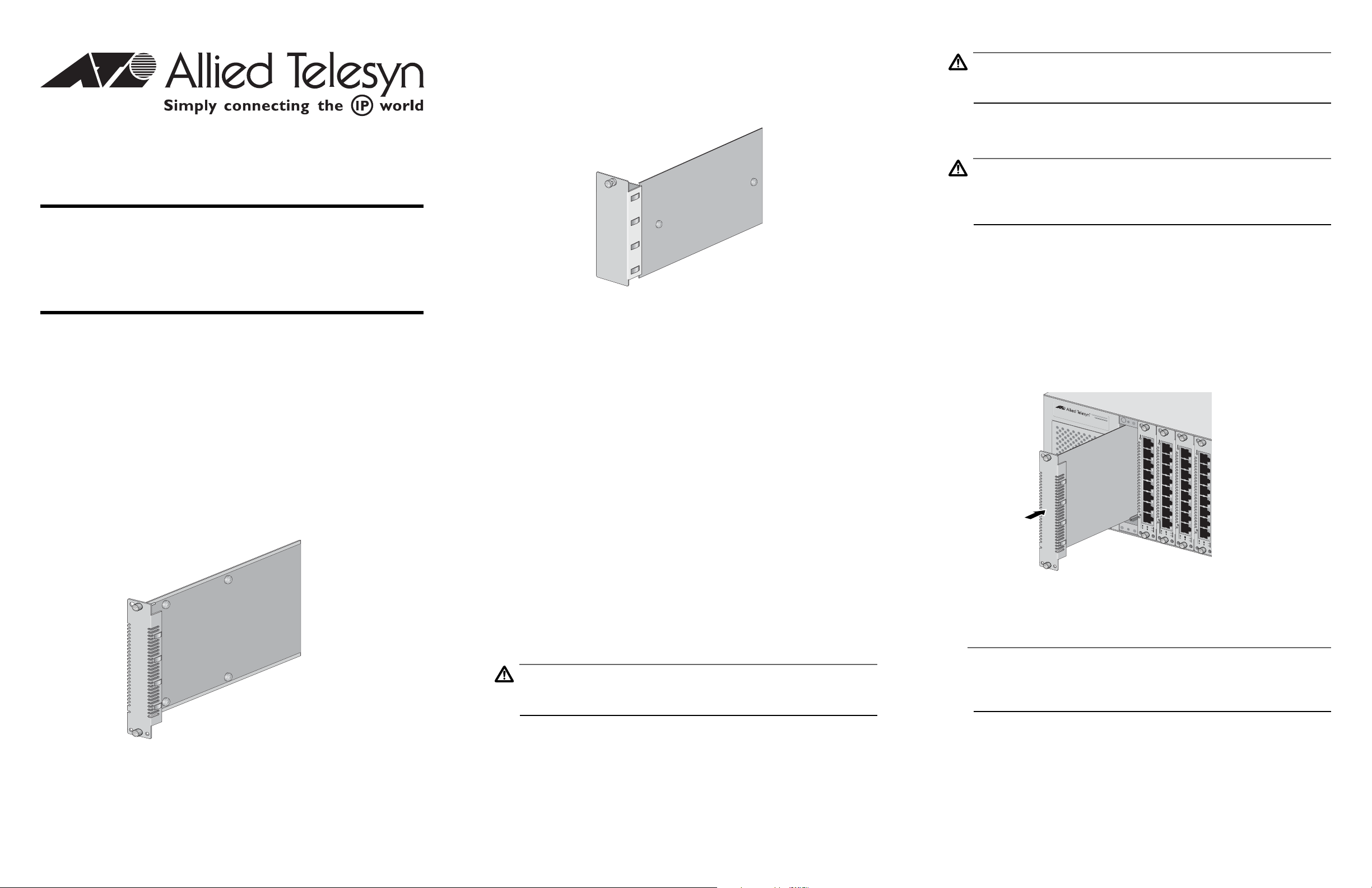
The AT-8400 chassis also requires a blank faceplate installed in any power
supply slot not occupied by a power supply. The power supply blank
faceplate (see Figure 2) ensures proper cooling and ventilation of the
AT-8400 chassis.
Caution
Do not install a blank faceplate in Slot M. Slot M is reserved for the
AT-8401 Management Fabric Card.
2. Unpack a blank faceplate from the shipping package, and store any
unused blank faceplates in a safe location.
Caution
Observe all standard electrostatic discharge (ESD) precautions, such
as wearing an antistatic wrist strap, to avoid damaging the chassis
device. Line cards can be damaged by static electricity.
Blank Faceplate
Installation Guide
For use with the AT-8400 Chassis
Allied Telesyn, Inc.
Visit our web site at: www.alliedtelesyn.com
Overview
AT-8400 blank faceplates are designed to maintain optimal, trouble-free
environmental conditions for the AT-8400 chassis. This installation guide
provides instructions for installing both the line card blank faceplate and
the power supply blank faceplate.
The AT-8400 chassis requires a blank faceplate installed in every chassis slot
that is not occupied by an Ethernet line card. The blank faceplate (see
Figure 1) keeps dust from getting into the switch and maintains proper
airflow throughout the chassis.
Figure 2. Power Supply Blank Faceplate
Related Documents
For complete details regarding the features, functions, and installation
instructions for the AT-8400 Chassis, refer to the AT-8400 Series Switch
Reference Guide (part number 613-50399-00) which is available from the
Allied Telesyn web site at www.alliedtelesyn.com.
Package Contents
Make sure the following items are included in your shipping package. If any
item is missing or damaged, contact your Allied Telesyn sales representative.
❑
Three AT-8400 line card blank faceplates
❑
One AT-8400 power supply blank faceplate
❑
Installation Guide
3. Verify that the blank faceplate package includes all the items previously
listed in “Package Contents” on page 2. If any item is missing or
damaged, contact your Allied Telesyn sales representative for
assistance.
4. Align the edge of the blank faceplate with the top and bottom guide
rails before carefully sliding the faceplate into the slot, as shown in
Figure 3. Slide the faceplate forward into the slot until the faceplate is
flush with the front of the chassis.
AT-8400
M
od
ular Sw
itch S
ystem
1
2
AT-8411
3
PWR
AT-8411
4
PWR
AT-8411
5
PWR
AT-8411
PWR
LNK
ACT
10
EJECT
100
LNK
ACT
10
EJECT
100
LNK
ACT
10
EJECT
100
LNK
ACT
10
EJECT
100
Figure 3. Insertion of Line Card Blank Faceplate
Installing the AT-8400 Line Card Blank Faceplate
You can install an AT-8400 line card blank faceplate whether the chassis is
5. Secure the blank faceplate to the chassis by using a Phillips screwdriver
to tighten the two installation screws on the faceplate.
powered on or powered off.
Note
Always tighten the installation screws to secure the blank faceplate to
the switch chassis. Leaving a faceplate partially seated can still allow
dust to enter the chassis and disrupt the normal air flow.
You have completed the line card blank faceplate installation procedure.
Figure 1. Line Card Blank Faceplate
Caution
Before installing an AT-8400 blank faceplate, refer to the AT-8400
Series Switch Reference Guide for electrical safety information.
To install an AT-8400 line card blank faceplate, perform the following
procedure:
1. Select the slot in the AT-8400 chassis where you need to install a blank
faceplate. You can install the faceplate in any slot marked 1 through 12.
PN 613-50540-00 Rev A 1 2 3
Page 2
Installing the AT-8400 Power Supply Blank Faceplate
You can install an AT-8400 power supply blank faceplate with the chassis
either powered on or powered off.
Caution
Before installing an AT-8400 blank faceplate, refer to the AT-8400
Series Switch Reference Guide for electrical safety information.
To install an AT-8400 power supply blank faceplate, perform the following
procedure:
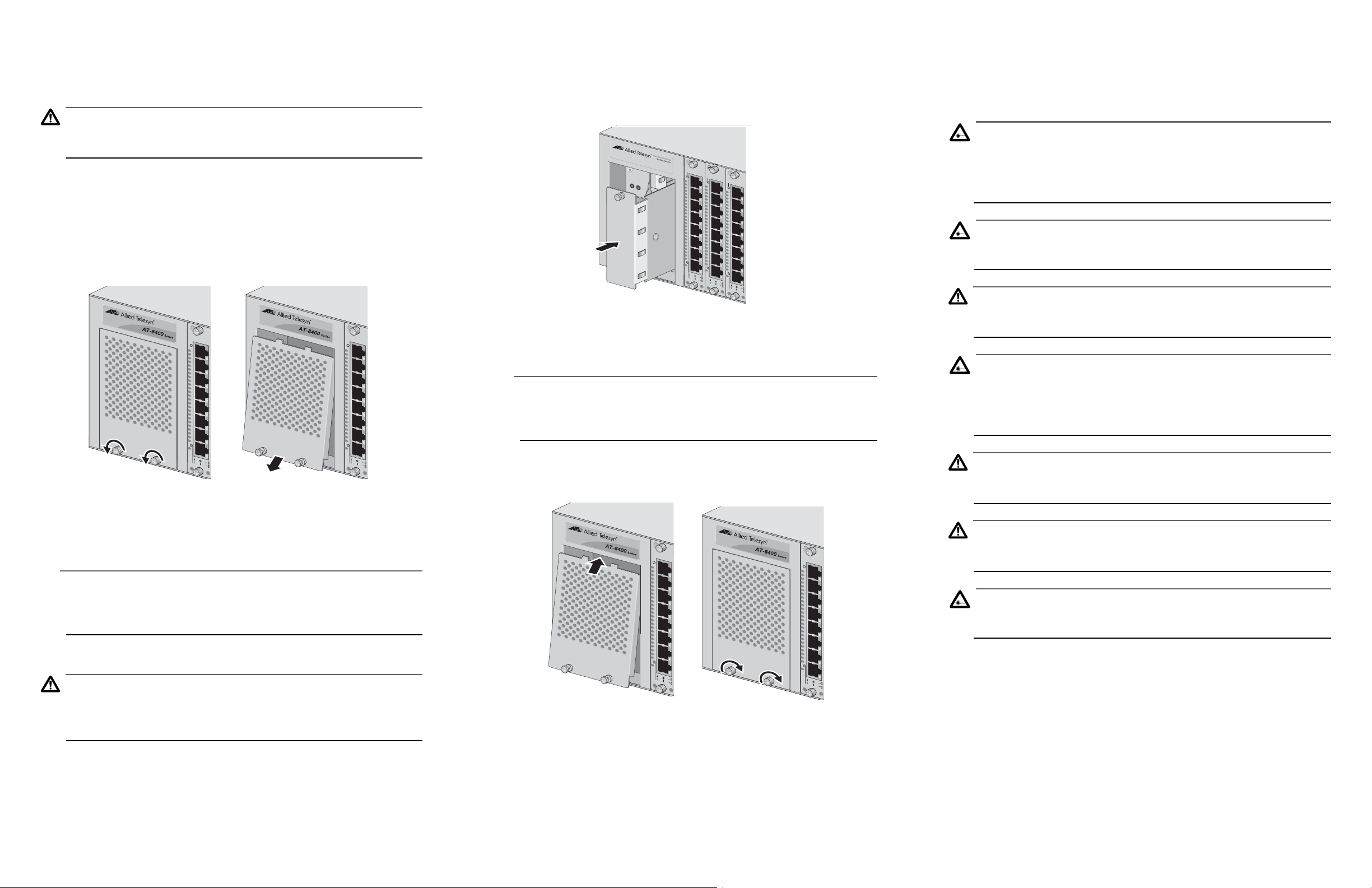
1. Begin by removing the power supply cover plate, as shown in Figure 4.
Use a Phillips screwdriver and loosen the two captive screws that secure
the power supply cover to the chassis. Remove the cover by angling it
from the bottom as you slide it down and out of the chassis.
1
AT-8411
TX
R
D
Y
1
AT-8411
TX
R
D
Y
5. Align the edge of the blank faceplate with the top and bottom guide
rails before carefully sliding the faceplate into the slot, as shown in
Figure 5. Slide the faceplate forward into the empty power supply slot
until the faceplate is flush with the adjacent power supply.
AT-8400
Modular Switch System
P
O
W
E
R
AT-PWR10
AC
F
A
U
L
T
1
AT-8411
2
PW
R
AT-8411
3
PW
R
AT-8411
PW
R
LNK
ACT
10
EJECT
100
LNK
ACT
10
EJECT
100
LNK
ACT
10
EJECT
100
Figure 5. Insertion of Power Supply Blank Faceplate
6. Secure the blank faceplate to the chassis by tightening the captive
screw on the faceplate.
Note
Always tighten the installation screw to secure the blank faceplate to
the switch chassis. Leaving a faceplate partially seated can allow dust
to enter the chassis and disrupt cooling and ventilation in the chassis.
Reviewing Safety Precautions
Please review the following safety precautions before you install an
AT-8400 line card blank faceplate or an AT-8400 power supply blank
faceplate.
Warning
Electric Shock Hazard: To prevent electric shock, do not remove the
AT-8400 chassis cover. There are no user-serviceable parts inside. The
unit contains hazardous voltages and should only be opened by a
trained and qualified technician. 8
Warning
Lightning Danger: Do not work on this equipment or connecting
cables during periods of lightning activity. 9
Caution
Power cord is used as a disconnection device: To de-energize
equipment, disconnect the power cord. 10
Warning
Electrical-Type Class 1 Equipment: This equipment must be
earthed. The power plug must be connected to a properly wired earth
ground socket outlet. An improperly wired socket outlet could place
hazardous voltages on accessible metal parts. 11
L
N
K
A
CT
1
0
E
J
E
1
0
C
0
T
L
N
K
A
CT
1
0
E
J
E
1
0
C
0
T
Figure 4. Removing the Power Supply Cover Plate
2. Select the power supply slot in the AT-8400 chassis that is unoccupied
by a power supply. Blank faceplates can be installed in either power
supply slot.
Note
Always cover any unoccupied AT-8400 power supply slot with a blank
faceplate. The faceplate ensures proper cooling and ventilation of the
AT-8400 Series switch.
3. Unpack the blank faceplate from the shipping package.
Caution
Observe all standard electrostatic discharge (ESD) precautions, such
as wearing an antistatic wrist strap, to avoid damaging the chassis
device.
4. Verify that the blank faceplate package includes all the items previously
listed in “Package Contents” on page 2. If any item is missing or
damaged, contact your Allied Telesyn sales representative for
assistance.
7. Slide the power supply cover back into the chassis and secure the cover
by tightening the two captive screws, as shown in Figure 6.
1
AT-8411
TX
R
D
Y
L
N
K
A
C
T
1
0
E
J
E
1
0
C
0
T
1
AT-8411
TX
R
D
Y
L
N
K
A
CT
1
0
E
J
E
1
0
C
0
T
Figure 6. Installing the Power Supply Cover Plate
You have completed the power supply blank faceplate installation
procedure.
Caution
Pluggable Equipment: The socket outlet should be installed near the
equipment and should be easily accessible. 12
Caution
Air vents: The air vents must not be blocked on the unit and must
have free access to the room ambient air for cooling. 13
Warning
Remove all metal jewelry, such as rings and watches, before installing
or removing a blank faceplate from a powered on chassis.
4 5 6
 Loading...