

Page 1

!
Installation
Fast Ethernet
®
Switches
AT-8316F/MT
AT-8316F/VF
AT-8316F/SC
AT-8324
Guide
PN 613-10813-00 Rev B
Page 2

Copyright 2003 Allied Telesyn, Inc.
960 Stewart Drive Suite B, Sunnyvale, CA 94086 USA
All rights reserved. No part of this publication may be reproduced without prior written permission from Allied Telesyn, Inc.
CentreCom is a registered trademark of Allied Telesyn, Inc.
All other product names, company names, logos or other designations mentioned herein are trademarks or registered trademarks of
their respective owners.
Allied Telesyn, Inc. reserves the right to make changes in specifications and other information contained in this document without
prior written notice. The informati on provided h erein is su bject to cha nge without n otice. In n o event sha ll Allied Telesyn, Inc. be liable
for any incidental, special, indirect, or consequential damages whatsoever, including but not limited to lost profits, arising out of or
related to this manual or the information contained herein, even if Allied Telesyn, Inc. has been advised of, known, or should have
known, the possibility of such damages.
Page 3
Electrical Safety and Emission Compliance
Statement
STANDARDS: This product meets the following standards
U.S. Federal Communications Commission
RADIATED ENERGY
Note: This equipment has been tested and found to comply with the limits for a Class A digital device pursuant to Part 15 of the FCC
Rules. These limits are designed to provide reasonable protection against harmful interference when the equipment is operated in a
commercial environment. This equipment generates, uses, and can radiate radio frequency energy and, if not installed and used in
accordance with this instruction manual, may cause harmful int erfer enc e to radio comm unication s. Operation of this equipment in
a residential area is likely to cause harmful interference in which case the user will be required to correct the interference at his own
expense.
Note: Modifications or changes not expressly approved by the manufacturer or the FCC can void your right to operate this
equipment.
Industry Canada
This Class A digital apparatus meets all requirements of the Canadian Interference-Causing Equipment Regulations.
Cet appareil numérique de la classe A respecte toutes les exigences du Règlement sur le matériel brouilleur du Canada.
RFI Emission EN55022 Class A
WARNING: In a domestic environment this product may cause radio interference in which case the user may be required t o take
adequate measures.
Immunity EN50082-1 1997
Electrical Safety EN60950, UL 1950, CSA 950
Laser EN60825
IMPORTANT: Appendix A contains translated safety statements for installing this equipment. When you see the ", go to Appendix A
for the translated safety statement in your language.
WICHTIG: Anhang A enthält übersetzte Sicherheitshinweise für die Installation dieses Geräts. Wenn Sie
Anhang A den übersetzten Sicherheitshinweis in Ihrer Sprache nach.
VIGTIGT: Tillæg A indeholder ove rsatte sikkerhedsadvarsler, der vedrører installation af dette udstyr. Når De ser symbolet
slå op i tillæg A og finde de oversatte sikkerhedsadvarsler i Dere s eget sprog.
BELANGRIJK: Appendix A bevat vertaalde veiligheidsopmerkingen voor het installeren van deze apparatuur. Wanneer u de
raadpleeg Appendix A voor vertaalde veiligheidsinstructies in uw taal.
IMPORTANT : L'annexe A contient les instructions de sécurité relatives à l'installation de cet équipement. Lorsque vous voyez le
symbole
", reportez-vous à l'annexe A pour consulter la traduction de ces instructions dans votre langue.
TÄRKEÄÄ: Liite A sisältää tämän laitteen asentamiseen liittyvät käännetyt turvaohjeet. Kun näet
turvaohjetta liitteestä A.
IMPORTANTE: l’Appendice A contiene avvisi di sicurezza tradotti per l’ins tallaz ione di questa apparecchiatura. Il simbolo
di consultare l’Appendice A per l’avviso di sicurezza nella propria lingua.
VIKTIG: Tillegg A inneholder oversatt sikkerhetsinformasjon for installering av dette utstyret. Når du ser
å finne den oversatte sikkerhetsinformasjonen på ønsket språ k.
" 2
" 1
" 3
" 4
" 5
" sehen, schlagen Sie in
", skal De
" ziet,
"-symbolin, katso käännettyä
", indica
", åpner du til Tillegg A for
IMPORTANTE: O Anexo A contém advertências de segurança traduzidas para instalar este equipamento. Quando vir o símbolo
leia a advertência de segurança traduzida no seu idioma no Anexo A.
IMPORT ANTE: El Apéndice A contiene mensajes de seguridad traducidos para la instalación de este equipo. Cuando vea el símbolo
",
", vaya al Apéndice A para ver el mensaje de seguridad traducido a su idioma.
OBS! Bilaga A innehåller översatta säkerhetsmeddelanden a vseende installationen av den na utrustning. När du ser
Bilaga A för att läsa det översatta säkerhetsmeddelandet på ditt språk.
", skall du gå till
3
Page 4

Page 5

Table of Contents
Preface ......................................................................................................................................................................................................................7
Purpose of This Guide ... .................................................. ......................................................................................................................................7
How This Guide is Organiz ed ................................................................................ .............................................................................................7
Document Conventions ......................................................................................................................................................................................8
Where to Find Related Guides ..................................................... ......................................................................................................................9
Chapter 1
Hardware Description .....................................................................................................................................................................................11
The Switch Models . ..............................................................................................................................................................................................12
Features and Components ...............................................................................................................................................................................13
Physical Description ............................................................................................................................................................................................14
Data Ports ................................................................................................................................................................................................................15
Switch LEDs ............................................................................................................................................................................................................16
RS232 Connector ..................................................................................................................................................................................................18
Stacking Ports ........................................................................................................................................................................................................19
Stacking Module Expansio n Slo t ....................................................................................................................................................................20
Stack ID Switch ............................................................................................... .......................................................................................................20
Expansion Module Slots ....................................................................................................................................................................................21
Optional Expansion Mo du le s................................................................................................. ................................................................. 21
R.P.S Input Connector ................................................................. ........................................................................................................................23
Reset Button ...........................................................................................................................................................................................................24
AC Power Connector ...........................................................................................................................................................................................25
AT-S25 Management Software and Omega Management Interface ......... .......................................................................................25
Network Topology ...............................................................................................................................................................................................26
Where to Go Next ................................................ .................................................................................................................................................28
Chapter 2
Planning the Installation ...............................................................................................................................................................................29
AT-8316F and AT-8324 Switch Cabling Specifications .................... .......................................................................................................30
Switch Stacks .........................................................................................................................................................................................................31
Stack of Two or Three Switc hes....................................... ....................................................................................................................... 3 1
Stack of Four to Eight Switches.................................................................................................................. ............................................ 32
Expansion Modules .............................................................................................................................................................................................33
Port Trunking .........................................................................................................................................................................................................35
Guideline 1: Number of Port s in a Tru nk............................................................................................................................................. 35
Guideline 2: Using Ports from the Same Group .............................................. ................................................. ................................ 35
Guideline 3: Creating Onl y One Trunk Per Group................................................................................................ ............................ 36
Guideline 4: Using Consecu ti v e Ports.. .................................................. .................................................. ............................................ 36
5
Page 6

Guideline 5: Cabling Based on Port Number..................................................................................................................................... 37
Guideline 6: Using Expansio n M odules.... ........................................................................................................................................... 37
Where to Go Next ................................................ .................................................................................................................................................38
Chapter 3
Installing the Switch .........................................................................................................................................................................................39
Verifying the Package Contents .....................................................................................................................................................................40
Reviewing Safety Precaut io ns .... .....................................................................................................................................................................41
Selecting a Site for the Switc h ............................. ............................................................................................................................................42
Installing the Switch as a Standalone Unit ............................................... ...................................................................................................43
Installing the Switch in a Rack ......................................... ................................................................................................................................45
Building a Stack of Two Switche s ....................... ............................................................................................................................................46
Building a Stack of Three Switc he s ........................ ........................................................................................................................................49
Building a Stack of Four to Eight Swit che s .................................................................................................................................................52
Powering On a Stack . ................................................................................................... .......................................................................................57
Setting Up a Terminal for Loc a l M anagement ...........................................................................................................................................59
Installing an Expansion Module ......................................................................................................................................................................60
Resetting a Stack .................... ..............................................................................................................................................................................62
Where to Go Next ................................................ .................................................................................................................................................63
Chapter 4
Troubleshooting ................................................................................................................................................................................................65
At the First Sign of a Proble m .................................. ................................................. .......................................................................................66
Network Cabling Proble ms ...................... ........................................................................... ..............................................................................67
Calling Technical Suppo rt ........................ ........................................................................... ..............................................................................67
How the Switch Reports Problems ................................................................................................................................................................68
Common Problems .............................................................................................................................................................................................70
Link /Activity LED on Any Port is OFF............................................................................................... .................................................... 70
Power LED is OFF......................................................................................................................................................................................... 71
Fault LED is ON........................................................................................................................ ..................................................................... 71
Appendix A
Translated Electrical Safety and Emission Information ..................................................................................................................73
Appendix B
Technical Specifications .................................................................................................................................................................................85
Appendix C
Switch Default Settings ..................................................................................................................................................................................89
Index ........................................................................................................................................................................................................................91
6
Page 7

Preface
Purpose of This Guide
This guide is intended for network administrators who are
responsible for installing and maintaining AT-8316F and AT-8324
Ethernet switches.
How This Guide is Organized
This guide contains the following chapters and appendices:
Chapter 1, Hardware Description, describes the features and
functions of the switches and the expansion modules. The chapter
also describes several network topologies that use the fast Ethernet
switches.
Chapter 2, Planning the Installation, contains cabling specifications
for the switches and expansion modules, and lists the rules to
observe when creating a port trunk.
Chapter 3, Installing the Switch, contains the procedures for
installing the switch, building a stack of switches, and installing the
expansion modu les.
Chapter 4, Troubleshooting, describes how to troubleshoot the
switch in case of a problem.
Appendix A, Translated Electrical Safety and Emission
Information, contains translations of the safety warnings
documented throughout this guide.
Appendix B, Technical Specifications, presents in tabular form
switch and expansion module specifications.
7
Page 8

Preface
Appendix C, Switch Default Settings, lists the switch’s factory
default software settings.
An Index, at the end of this guide, is according to subject matter.
Document Conventions
The conventions used in this guide are as follows:
# Notes:
Note
A note provides additional information.
# Warnings:
Warning
A warning indicates that performing or omitting a specific action
may result in bodily injury.
# Cautions:
Caution
A caution indicates that performing or omitting a specific action
may result in equipment damage or loss of data.
8
Page 9

Where to Find Related Guides
After you have performed the procedures in this guide and installed
the switch on your network, go to the Allied Telesyn web site at
www.alliedtelesyn.com and download the following guide:
AT-S25 Management Software User’s Guide
PN 613-10844-00
This manual explains how to use the Omega management software
and the AT-S25 software to configure and manage the device.
AT-8316F and AT-8324 Installation Guide
9
Page 10

Page 11

Chapter 1
Hardware Description
The AT-8316F and the AT-8324 switches are designed to provide
your network with Ethernet, Fast Ethernet, and Gigabit Ethernet
connectivity over fiber optic and twisted pair cabling.
The switches can operate as standalone units or can be
interconnected together through special stacking ports to form
logical switches. Logical switches, also referred to as s tacks, can make
it easier for you to manage your network because you can manage
all of the switches as one unit. Logical switches are also easy to
customize. You can add or remove switches from a logical switch so
that the unit always has the number and types of ports that your
network requires.
Two expansion slots on the front of the switches further add to the
flexibility of the systems. You can use the slots to install 10Base-T,
100Base-TX, 100Base-FX, and 1000Base-FX expansion modules.
This chapter describes the hardware features of the following
products:
# AT-8316F/MT switch
# AT-8316F/VF switch
# AT-8316F/SC switch
# AT-8324 switch
# The optional expansion modules: AT-A15/SX, AT-A15/LX,
AT-A16, AT-A17, AT-A18, and AT-A19
11
Page 12
Hardware Description
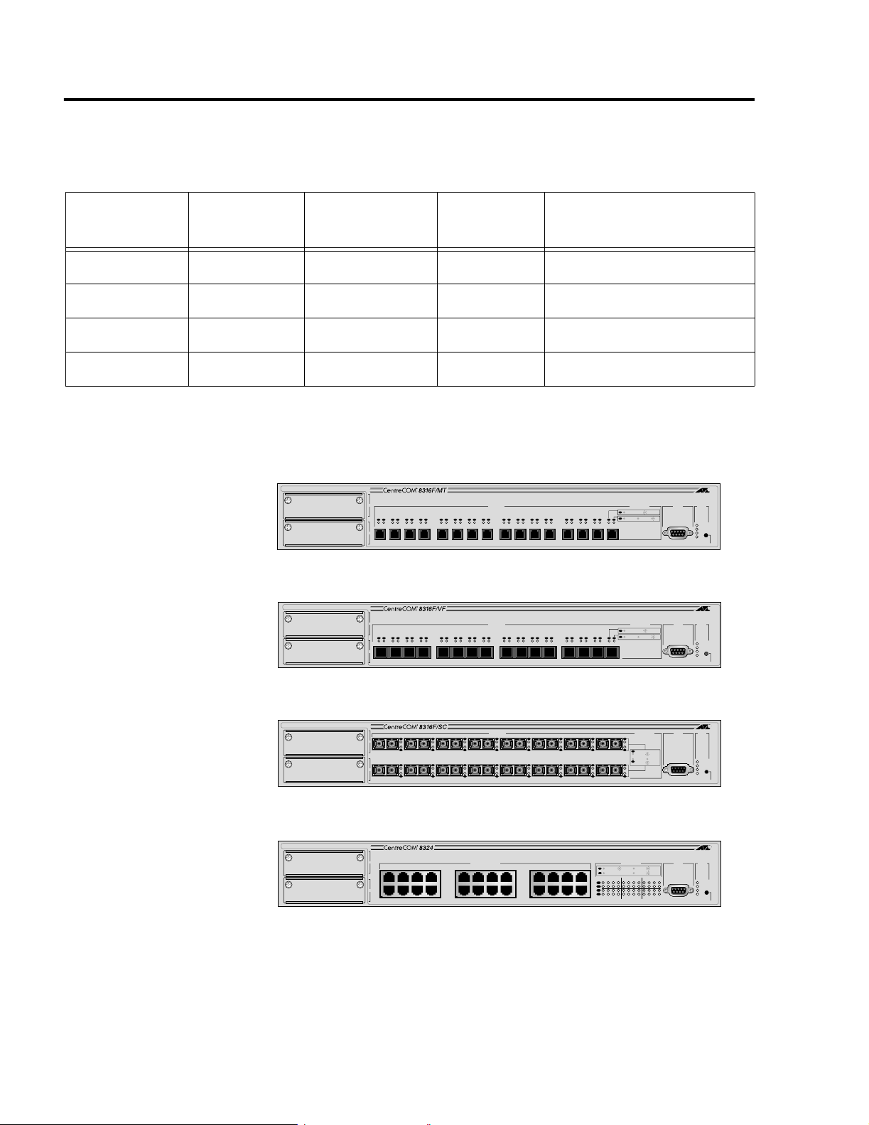
The Switch Models
Table 1-1 lists the switch models.
Table 1-1 Switch Models
Model
1
Number of
Ports
Type of Port
Type of
Connector
Maximum Distance
AT-8316F/MT 16 100Base-FX MT-RJ 2 kilometers2 (1.25 miles)
AT-8316F/VF 16 100Base-FX VF-45 2 kilometers2 (1.25 miles)
AT-8316F/SC 16 100Base-FX SC 2 kilometers2 (1.25 miles)
AT-8324 24 10/100Base-TX RJ-45 100 meters (328 feet)
1. All models include two expansion slots.
2. Assumes 50/125 micron or 62.5/125 micron multimode fiber optic cabling and full-duplex operation.
Figure 1-1 shows the front panel of each switch.
100BASE-FX FAST ETHERNET SWITCH
A
L/A
L/A
L/A
L/A
L/A
D/C
D/C
B
1 2 3 4 5 6 7 8 9 10 11 12 13 14 15 16
D/C
D/C
D/C
100BASE-FX
L/A
L/A
L/A
L/A
L/A
L/A
D/C
D/C
D/C
D/C
D/C
D/C
L/A
L/A
L/A
D/C
D/C
D/C
AT-8316/MT
100BASE-FX FAST ETHERNET SWITCH
A
L/A
L/A
L/A
L/A
L/A
D/C
D/C
B
1234 5678 9101112 13141516
D/C
D/C
D/C
100BASE-FX
L/A
L/A
L/A
L/A
L/A
L/A
D/C
D/C
D/C
D/C
D/C
D/C
L/A
L/A
L/A
D/C
D/C
D/C
AT-8316F/VF
PORT ACTIVITY
L/A
ACTIVITY
100M LINK
D/C
FULL DUP
HALF DUP/ COL
L/A
L/A
D/C
D/C
PORT ACTIVITY
L/A
ACTIVITY
100M LINK
D/C
FULL DUP
HALF DUP/ COL
L/A
L/A
D/C
D/C
RS-232
TERMINAL PORT
RS-232
TERMINAL PORT
STATUS
FAULT
MASTER
RPS
PWR
RESET
STATUS
FAULT
MASTER
RPS
PWR
RESET
12
A
B
100BASE-FX FAST ETHERNET SWITCH
L/A
D/C
L/A
D/C
L/A
D/C
L/A
D/C
100BASE-FX
L/A
L/A
L/A
D/C
L/A
D/C
D/C
D/C
L/A
L/A
D/C
D/C
L/A
L/A
D/C
D/C
L/A
L/A
D/C
D/C
PORT ACTIVITY
87654321
L/A
D/C
L/A
RXTXRXTXRXTXRXTXRXTXRXTXRXTXRXTX
LINK / ACTIVITY
FULL DUP /
D/C
161514131211109
L/A
D/C
RXTXRXTXRXTXRXTXRXTXRXTXRXTXRXTX
AT-8316F/SC
10BASE-T / 100BASE-TX
FAST ETHERNET SWITCH
A
B
1X 3X 5X 7X
2X 4X 6X 8X
10BASE-T / 100BASE-TX
9X 11X 13X 15X
10X 12X 14X 16X
17X 19X 21X 23X
18X 20X 22X 24X
PORT ACTIVITY
L/A
100M LINK / ACTIVITY 10M LINK / ACTIVITY
D/C
HALF DUP/
FULL DUP
1234567891011121314151617181920212223
L/A
D/C
L/A
D/C
AT-8324
Figure 1-1 AT-8316F and AT-8324 Swi tches
STATUS
RS-232
TERMINAL PORT
HALF DUP
COL
COL
FAULT
MASTER
RPS
PWR
RESET
STATUS
RS-232
TERMINAL PORT
FAULT
MASTER
RPS
PWR
24
RESET
Page 13

Features and Components
The switches have the following common hardware features:
# Half- or full-duplex operation on all switched ports delivering
up to 200 Mbps of bandwidth to servers, routers, workstations,
or other switches
# Auto-negotiation on all 10Base-T/100Base-TX ports for speed
and duplex in compliance with IEEE 802.3u specifications
(AT-8324 switch only)
# Non-blocking, clear-channel architecture delivers wire-speed
switching and up to 14 Gbps aggregate bandwidth
# Store-and-forward switching mode
# 8K MAC addresses per switch with automatic aging
# 4 MB SDRAM per eight 10Base-T/100Base-TX or 100Base-FX
ports
AT-8316F and AT-8324 Installation Guide
# 2 MB Flash memory for software upgrades
# In-band Telnet capability for remote switch management
# AT-S25 software and Omega management software
# Two stacking ports for interconnecting switches to create
logical switches
# One expansion slot for the optional AT-Stack8 Stacking Matrix
Module for creating logical switches of up to eight switches
# Two expansion slots for optional uplink expansion modules
# RS232 connector for local switch management
# IEEE 802.1Q compliant Virtual LAN (VLAN) tagging support
# IEEE 802.1P compliant Quality of Service
# Two priority queues/levels per-port based on tagging
information (IEEE 802.1P)
# IEEE 802.1d Spanning Tree Protocol
# SNMP Management Information Base (MIB) II, SNMP MIB
extensions, Bridge MIB (RFC 1493), Ethernet MIB (RFC 1643),
and Interface MIB (RFC 1573)
# BootP and DHCP support
# Port trunking for increased bandwidth to end nodes
13
Page 14
Hardware Description
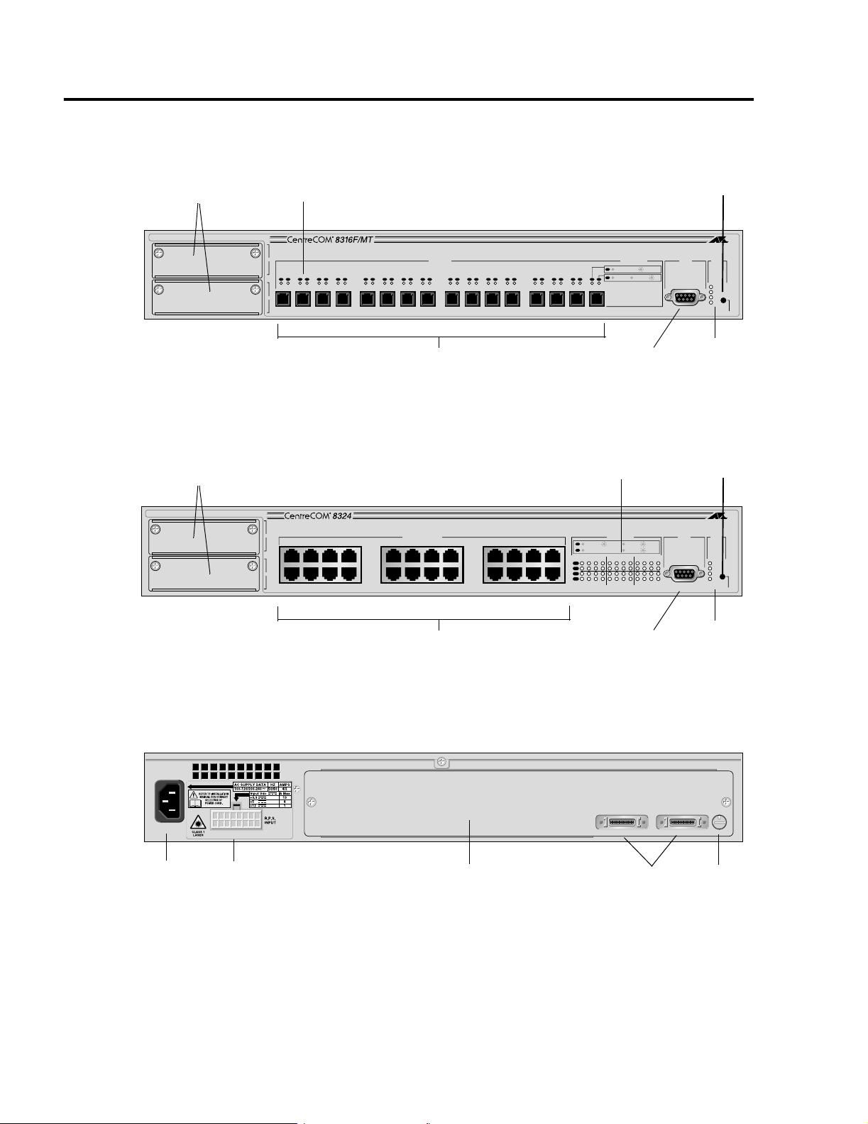
Physical Description
Figure 1-2 through Figure 1-4 illustrate the location of the switch
components.
Expansion Module Slots
Expansion Module Slots
Port LEDs
100BASE-FX FAST ETHERNET SWITCH
A
L/A
L/A
L/A
L/A
L/A
L/A
B
D/C
D/C
D/C
1 2 3 4 5 6 7 8 9 10 11 12 13 14 15 16
D/C
D/C
100BASE-FX
L/A
L/A
L/A
L/A
L/A
L/A
L/A
L/A
D/C
D/C
D/C
D/C
D/C
D/C
D/C
D/C
Sixteen 100Base-FX Ports
Figure 1-2 AT-8316F Switch (Model AT-8316F/MT)
10BASE-T / 100BASE-TX
FAST ETHERNET SWITCH
A
1X 3X 5X 7X
B
2X 4X 6X 8X
10BASE-T / 100BASE-TX
9X 11X 13X 15X
10X 12X 14X 16X
17X 19X 21X 23X
18X 20X 22X 24X
L/A
L/A
D/C
D/C
D/C
RS232 connector
Port LEDs
L/A
100M LINK / ACTIVITY 10M LINK / ACTIVITY
D/C
FULL DUP
1234567891011121314151617181920212223
L/A
D/C
L/A
D/C
L/A
100M LINK
D/C
FULL DUP
PORT ACTIVITY
PORT ACTIVITY
HALF DUP/ COL
HALF DUP/
ACTIVITY
COL
24
Reset Button
STATUS
RS-232
TERMINAL PORT
FAULT
MASTER
RPS
PWR
System
LEDs
Reset Button
STATUS
RS-232
TERMINAL PORT
FAULT
MASTER
RPS
PWR
RESET
RESET
AC
Connector
R.P.S. Input
Connector
Twenty Four 10Base-T/100Base-TX Ports
RS232 connector
System
LEDs
Figure 1-3 AT-8324 Swi tch
STACK ID
IS-A IS-B
IS-A IS-B
Expansion Slot
Stacking Module
Stacking Ports
STACK ID
0
0
Stack ID
Switch
Figure 1-4 Switch Back Panel
14
Page 15

Data Ports
AT-8316F and AT-8324 Installation Guide
Each model of the AT-8316F switch features 16 fiber optic ports with
either MT-RJ, VF-45, or SC fiber optic connectors. The ports offer
100Base-FX performance and half- or full-duplex operation. Each
port can operate up to a maximum distance of 2 kilometers (1.25
miles), assuming 50/125 micron or 62.5/125 micron multimode fiber
optic cabling and full-duplex operation.
The AT-8324 switch has 24 twisted pair ports with RJ-45 connectors.
The ports, which feature auto-negotiation on both speed and duplex
mode, can operate as either 10Base-T or 100Base-TX ports and in
half- or full-duplex mode.
15
Page 16
Hardware Description
STATUS
RESET
FAULT
MASTER
RPS
PWR
RS-232
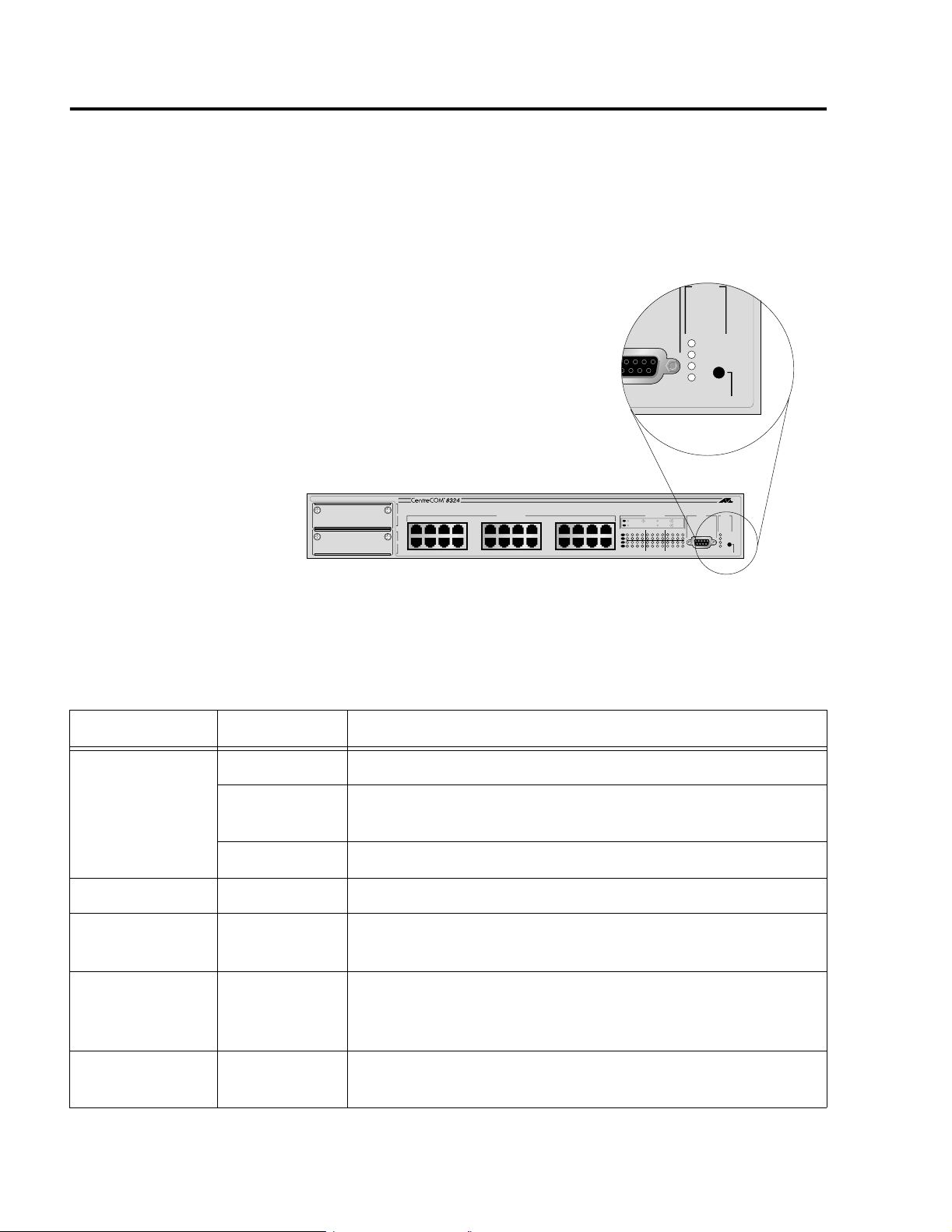
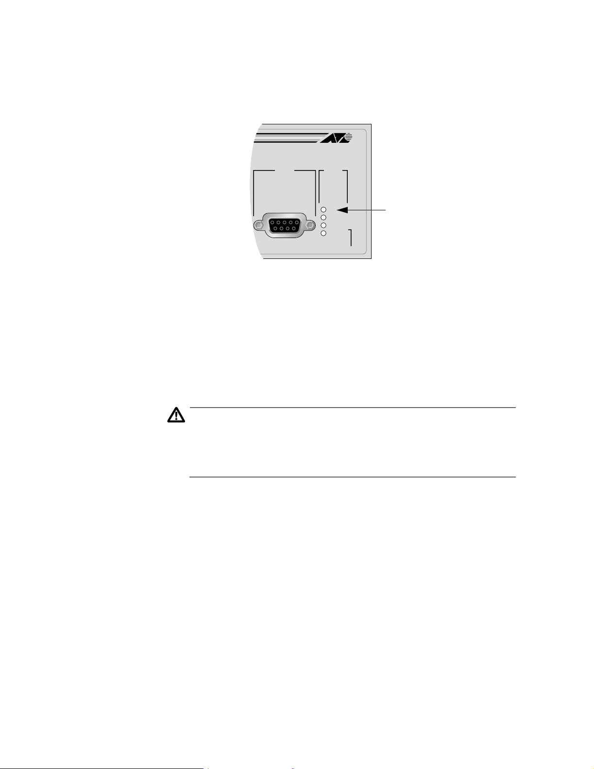
Switch LEDs
The Ethernet switch has a series of LEDs for monitoring the status of
the unit. There are system LEDs for monitoring the entire switch and
port LEDs for monitoring the individual data ports.
The system LEDs are Fault, Master, RPS (Redundant Power Supply),
and PWR. Figure 1-5 illustrates the location of the system LEDs. The
location of the system LEDs is the same on all switch models.
10BASE-T / 100BASE-TX
FAST ETHERNET SWITCH
A
B
1X 3X 5X 7X
2X 4X 6X 8X
10BASE-T / 100BASE-TX
9X 11X 13X 15X
10X 12X 14X 16X
17X 19X 21X 23X
18X 20X 22X 24X
PORT ACTIVITY
L/A
100M LINK / ACTIVITY 10M LINK / ACTIVITY
D/C
HALF DUP/
FULL DUP
1234567891011121314151617181920212223
L/A
D/C
L/A
D/C
COL
STATUS
RS-232
TERMINAL PORT
FAULT
MASTER
RPS
PWR
24
RESET
Figure 1-5 System LEDs
Table 1-2 describes the system LEDs on the Ethernet switch.
Table 1-2 Switch System LED Status
LED State Description
Fault Solid Red The switch or management software is malfunctioning.
Flashing Red The switch is booting, running diagnostic tests, writing
messages to FLASH, or transferring files using XMODEM.
OFF Normal operation.
Master Solid Amber The switch is functioning as the master switch of the stack.
Off The switch is functioning as a slave switch in the stack or is
not a part of a stack.
RPS (Redundant
Power Supply)
Solid Green The RPS is connected to the switch. To verify that the RPS is
operating correctly, refer to the instructions in the RPS
Quick Install Guide.
Power Solid Green The switch is receiving power, the voltage is within the
acceptable range, and the power supply is working.
16
Page 17

AT-8316F and AT-8324 Installation Guide
Each port has two LEDs that reflect the operating status of the port.
On the AT-8316F switch, the port LEDs are located directly above or
next to each port. On the AT-8324 switch, the port LEDs are grouped
together on the right side of the switch. Table 1-3 describes the port
LEDs on the Ethernet switch.
Table 1-3 Switch Port LED Status
LED State Description
L/A (Link/Activity) Solid Green This indicates a 100 Mbps link.
Flashing Green This indicates 100 Mbps activity.
Solid Amber This indicates a 10 Mbps link (AT-8324 switch
only).
Flashing Amber This indicates 10 Mbps activity (AT-8324 switch
only).
D/C (Duplex/Collision) Solid Green The port is operating at full-duplex.
Solid Amber The port is operating at half-duplex.
Flashing Amber Collisions are occurring on the line.
17
Page 18
Hardware Description
STATUS
RE
FAULT
MASTER
RPS
PWR
212223
24
RS-232
TERMINAL PORT
ACTIVITY
COL
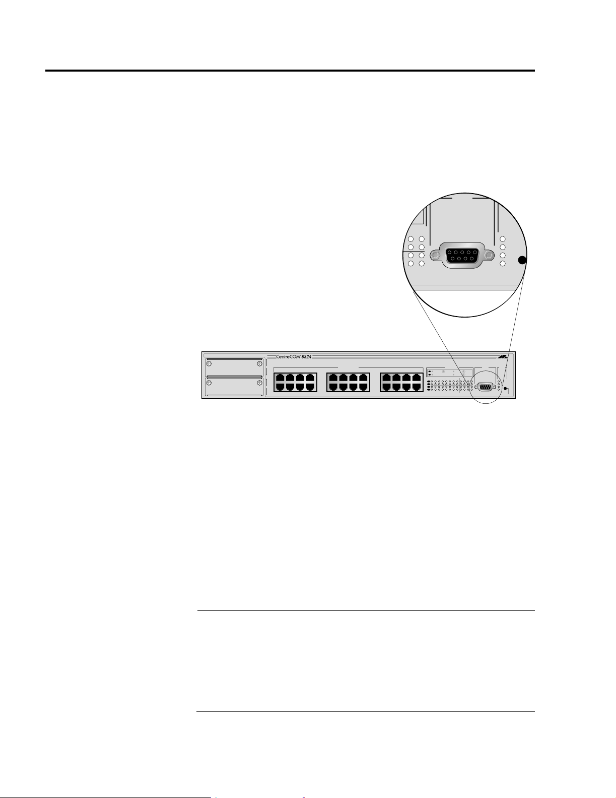
RS232 Connector
The RS232, DB-9 female port on the front of the switch (shown in
Figure 1-6) is used with a VT100 terminal to manage the system. By
connecting a terminal to the connector (or by using a personal
computer with a terminal emulation program, such as the MSWindows’ Hyper Terminal emulation program), you can access the
pre-installed Omega management program and configure the
switch.
18
10BASE-T / 100BASE-TX
FAST ETHERNET SWITCH
A
B
1X 3X 5X 7X
2X 4X 6X 8X
10BASE-T / 100BASE-TX
9X 11X 13X 15X
10X 12X 14X 16X
17X 19X 21X 23X
18X 20X 22X 24X
PORT ACTIVITY
L/A
100M LINK / ACTIVITY 10M LINK / ACTIVITY
D/C
HALF DUP/
FULL DUP
1234567891011121314151617181920212223
L/A
D/C
L/A
D/C
COL
24
RS-232
TERMINAL PORT
STATUS
FAULT
MASTER
RPS
PWR
RESET
Figure 1-6 RS232 Port
This method for accessing the Omega program is referred to as “local
access” or “out-of-band” access. You can also access the program
over the web with a web browser or remotely via Telnet or an SNMP
management program.
In an IP environment, after you have initially installed the switch you
will be required to access the Omega program through the RS232
port in order to assign the switch its IP address and, if necessary, a
gateway address. Once these addresses have been assigned, you can
either continue to manage the switch through the RS232 port or
access the program via one of the other available methods.
Note
Only the RS232 port on the master switch in a stack can be used to
configure a stack locally. The RS232 ports on the slave switches are
inactive and cannot be used. (For an explanation of master and
slave switches, refer to , Chapter 3, Installing the Switch.)
Additionally, a straight-through cable is required in order to
connect a terminal to the RS232 port on the master switch.
Page 19
Stacking Ports
IS-A IS-B
STACK ID
0
AT-8316F and AT-8324 Installation Guide
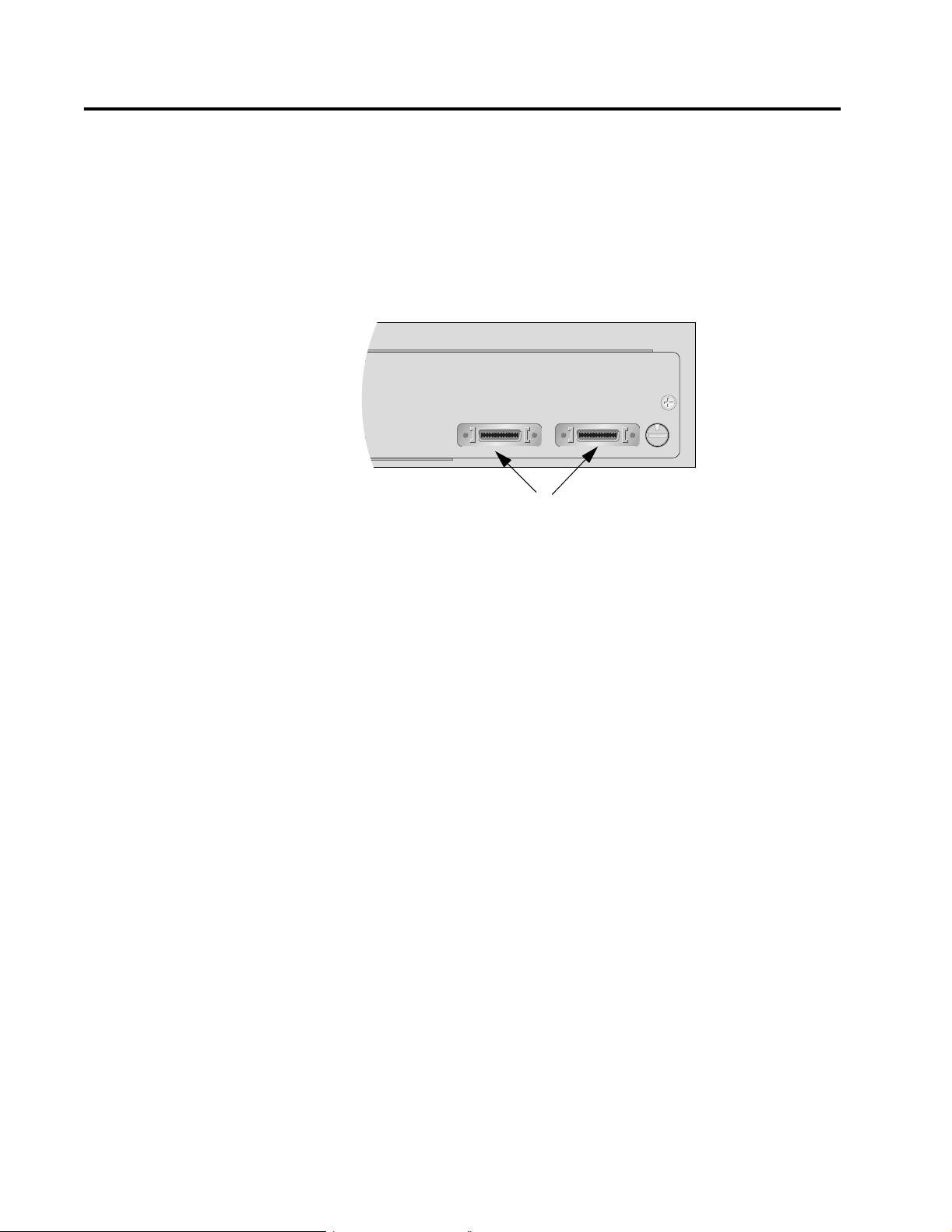
On the back of the switch are two stacking ports (Figure 1-7). The
ports are used to interconnect AT-8316F and AT-8324 switches to
form logical switches. A logical switch consists of two or more
individual switches that function as one unit. This feature allows you
to build a switch that is customized to the needs and requirements of
your network. It also makes it easier to manage them since, rather
than having to mange the switches individually, you can manage all
the switches as one unit.
Stacking Ports
Figure 1-7 Stacking Ports
Interconnecting two or more AT-8316F or AT-8324 switches creates
what is referred to as a stack. A stack can consist of either the same
type of Ethernet switches or different types of switches. For example,
a stack can consist of a combination of AT-8316F/MT and AT-8324
switches. The result would be one logical switch, where the
individual switches themselves were different in the number and
types of ports.
Each stacking port provides two gigabits of full-duplex bandwidth
between switches. A stack of two or three switches does not require
any additional hardware other than the switches and the
AT-CABLE-4 cables that comes with the units. Creating a stack of four
to eight switches requires the optional AT-Stack8 Stacking Matrix
Module.
19
Page 20
Hardware Description
STACK ID
1
Stacking Module Expansion Slot
The stacking module expansion slot on the back panel of the switch
is for the optional AT-Stack8 Stacking Matrix Module. This module
allows you build a logical switch of up to eight switches.
Stack ID Switch
Next to the stacking ports on the back panel of the switch is the Stack
ID switch (shown in Figure 1-8). You use this switch when you build a
stack to assign each switch a unique identification number.
IS-A IS-B
STACK ID
0
Figure 1-8 Stac k ID Switch
Note
While the Stack ID switch has the range of settings of 0 to 9, only
settings 1 through 8 are valid settings. Settings of 0 and 9 are
invalid and should not be used. For information on setting this
switch, refe r t o Chapter 3, Installing the Switch .
20
Page 21
Expansion Module Slots
10BASE-T / 100BASE-TX
FAST ETHERNET SWITCH
1X 3X
2X 4X
A
B
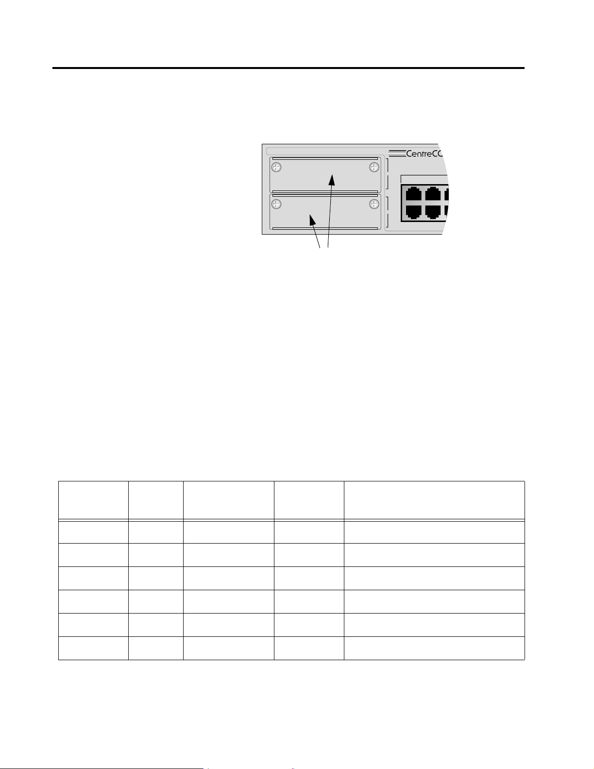
The capabilities of the AT-8316F and AT-8324XL Ethernet switches
can be expanded by installing optional expansion modules in the
two expansion slots on the front of the switches (shown in Figure
1-9).
The modules offer you flexibility in building or expanding your
network. For example, you can use the modules to build a highspeed backbone network between different switches, to expand the
number of ports on a switch for additional nodes, or to provide a
high-speed connection to shared devices, such as servers or routers.
AT-8316F and AT-8324 Installation Guide
Expansion Slots
Figure 1-9 Expansion Slot s
Optional
Expansion
Modules
Table 1-4 lists the optional expansion modules for the AT-8316F and
AT-8324 Ethernet switches. The modules can be installed in any
combination in the switch. For example, you can install an AT-A15/LX
module in one expansion slot and an AT-A18 module in the second
expansion slot of the same switch.
Table 1-4 Optional Expansion Modules
Module
Number
of Ports
Type of Port
AT-A15/SX 1 1000Base-SX SC 550 meters
Type of
Connector
Maximum Distance
1
(1,804 feet)
AT-A15/LX 1 1000Base-LX SC 10 kilometers2 (6.2 miles)
AT-A16 2 100Base-FX VF-45 2 kilometers3 (6,600 feet)
AT-A17 2 100Base-FX SC 2 kilometers3 (6,600 feet)
AT-A18 4 10/100Base-TX RJ-45 100 meters (328 feet)
AT-A19 2 100Base-FX MT-RJ 2 kilometers
1. Assumes 50/125 micron multimode fiber optic cabling.
2. Assumes 9/125 micron single-mode fiber optic cabling.
3. Assumes 50/125 micron or 62.5/125 micron multimode fiber optic cabling and full-duplex operation.
3
(6,600 feet)
21
Page 22
Hardware Description
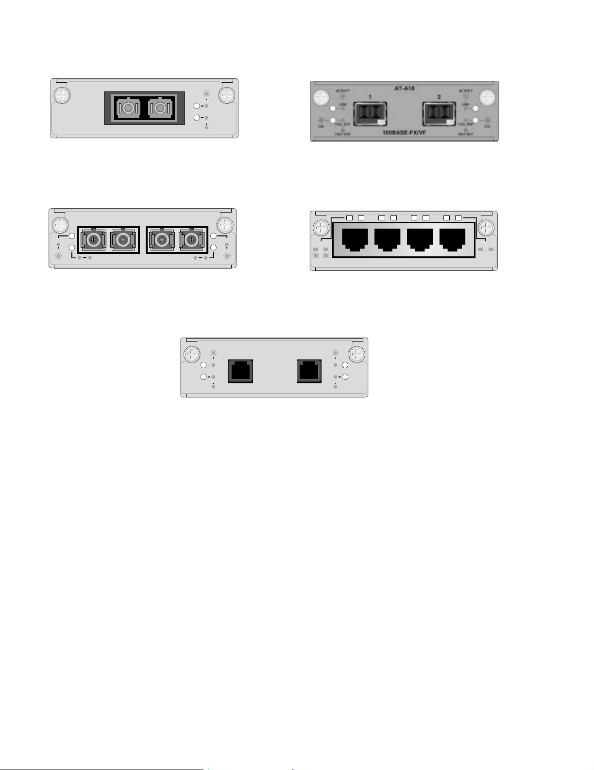
Figure 1-10 illustrates the front panels of the expansion modules.
LINK
ACTIVITY
AT-A15
1000BASE-X
AT-A15 (SX or LX)
AT-A17
RXTX RXTX
100BASE-FX/SC
AT-A17
ACTIVITY
LINK
FULL
HALF
AT-A16
2X 3X 4X1X
LINK
ACTIVITY
FULL HALFFULL HALF
100M
LINK
ACTIVITY
10M
LINK
AT-A18
10BASE-T/100BASE-TX
FULL
DUPLEX
HALF
DUPLEX
AT-A18
ACTIVITY
LINK
AT-A19
ACTIVITY
LINK
FULL
HALF
100BASE-FX/MT
FULL
HALF
AT-A19
Figure 1-10 Optional Expansion Modules
22
Page 23
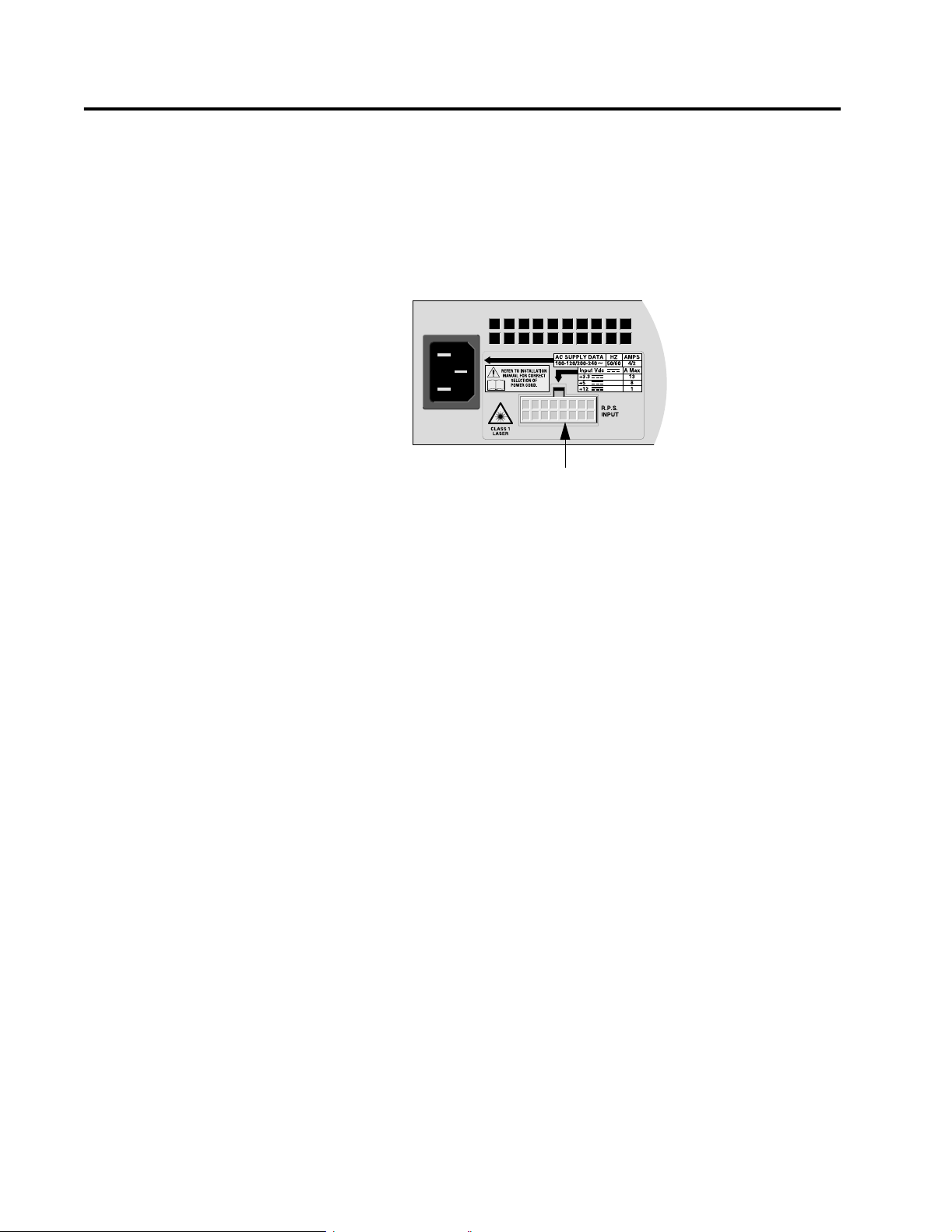
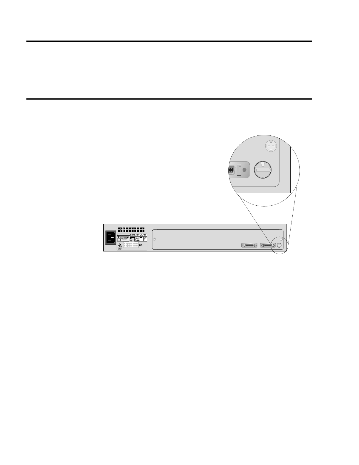
R.P.S Input Connector
On the back panel of the Ethernet switch is a connector labelled
R.P.S. Input (shown in Figure 1-11). This connector is used to connect
the switch to a redundant power supply (RPS) unit. The RPS shares
the load of powering the switch with the standard power supply that
comes with the Ethernet switch. If one power supply fails, the
remaining unit provides all power to the switch, thus protecting the
switch from a system failure.
AT-8316F and AT-8324 Installation Guide
R.P.S Input Connector
Figure 1-11 R.P.S Input Connector
Allied Telesyn offers the AT-RPS8000 redundant power supply
system for the AT-8316F and AT-8324 switches. The RPS system
comes with one redundant power module pre-installed that can
support one Ethernet switch. The AT-RPS8000 unit has three
expansion slots for three additional redundant power modules, each
of which can support an additional switch. Contact your Allied
Telesyn representative for more information about the AT-RPS8000
redundant power supply unit.
23
Page 24

Hardware Description
Reset Button
The Reset button on the front panel of the switch resets the switch. It
is primarily used for diagnostics or resetting the switch statistics
stored by the AT-S25 management software. You can also reset the
switch using the Omega management interface, as explained in the
AT-S25 Management Software User’s Guide. This guide is
available from the Allied Telesyn web site at www.alliedtelesyn.com/
techhome.htm.
Note
If it becomes necessary to reset a switch that is a part of a stack, you
must reset all of the switches in the stack. You cannot reset just one
switch in a stack. Additionally, you should reset the slave switches
first, then the master switch. For information on slave and master
switches, refer to Chapter 3, Installing the Switch.
24
Page 25

AT-8316F and AT-8324 Installation Guide
AC Power Connector
The switch has a single AC power supply socket on the back panel,
which has autoswitch AC inputs. The input voltage range is from
100-120/200-240 VAC, 4/2A, 50/60 Hz. The power cord acts as an ON/
OFF switch.
AT-S25 Management Software and Omega Management Interface
The AT-S25 software is the management program for the switch, and
it comes pre-installed on the unit. Included with the AT-S25 software
is the Omega management interface. This menu oriented interface
makes it easy for you to manage the system. With Omega, you can
perform all of the tasks necessary to configuring and monitoring the
system, such as creating VLANs, assigning operational parameters to
the switch, such as an IP address and gateway address, and viewing
switch statistics, all through menu selections and easy-to-use
windows.
In a network environment where you have created a stack of
Ethernet switches, you will use the Omega management interface to
manage all of the switches in the stack as a unit, that is, as one logical
switch. You will not manage each switch in a stack separately.
There are several different methods for accessing the Omega
management interface on an Ethernet switch:
# RS-232 connector on the switch
# Web browser
# Telnet program
# SNMP network management program
The Omega interface functions the same and has the same
capabilities regardless of the method you choose to access it. The
program has security features that allow you to disable one or more
of the access methods to prevent unauthorized access to a switch.
The program also has a password security feature.
Note
For instructions on how to access and how to use the Omega
management interface, refer to the AT-S25 Management
Software User’s Manual. This guide is available from the Allied
Telesyn web site at www.alliedtelesyn.com/techhome.htm.
25
Page 26

Hardware Description
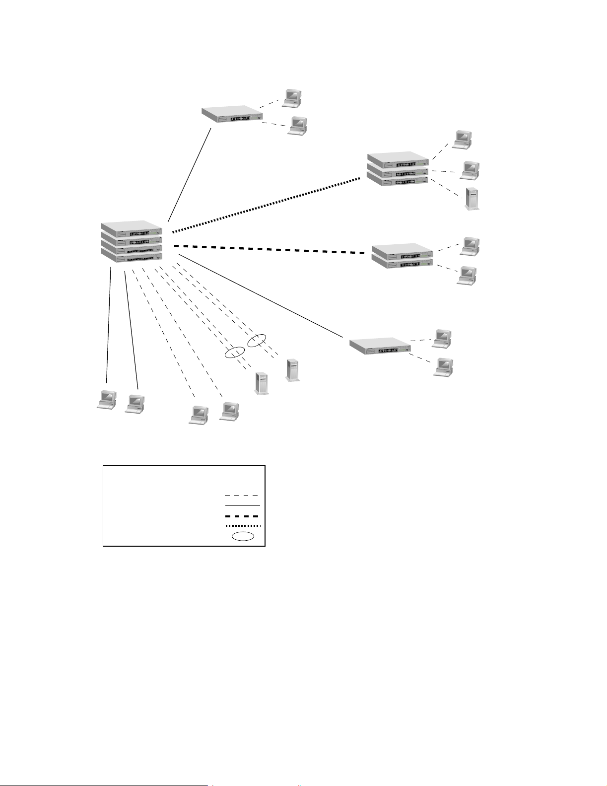
Network Topology
Figure 1-12 is an example of a network consisting of AT-8316F and
AT-8324 Ethernet switches. Some of the features of the network
include the following:
# Though the Sales and Technical Support workgroups are
distributed between several sites, the 802.1Q VLAN
capabilities of the switches allow you to easily separate their
traffic, improving network performance and enhancing
network security as well.
# The stack of four switches at site 1 are interconnected with an
AT-Stack8 stacking module.
# Port trunking at site 1 provides 200 Mbps of full-duplex
operation to the network servers in the server farm.
# Expansion modules in the switches provide interconnections
between the various sites. For example, site 1 and site 2 each
have AT-A15/LX expansion modules to provide 1000Base-LX
performance up to a maximum distance of 10 kilometers (6.2
miles).
26
Page 27
Site 1:
AT-8324 and
AT-8316F
stack
X
T
E
S
A
B
0
0
1
/
T
E
S
A
B
0
1
X
T
E
S
A
B
0
0
1
/
T
E
S
A
B
0
1
H
C
T
I
W
S
T
E
N
R
E
H
T
E
T
S
A
F
X
T
-
E
S
A
B
0
0
1
/
T
E
S
A
B
0
1
X
T
E
S
A
B
0
0
1
/
T
E
S
A
B
0
1
H
C
T
I
W
S
T
E
N
R
E
H
T
E
T
S
A
F
X
T
E
S
A
B
0
0
1
/
T
-
X
E
T
S
-
A
E
B
S
0
A
1
B
0
H
0
C
1
T
/
I
T
W
-
S
E
T
S
E
A
N
B
R
0
E
1
H
T
E
T
S
A
F
X
T
E
S
A
B
0
0
1
/
T
-
X
E
T
S
-
A
E
B
S
0
A
1
B
0
H
0
C
1
T
/
I
T
W
-
S
E
T
S
E
A
N
B
R
0
E
1
H
T
E
T
S
A
F
AT-8316F and AT-8324 Installation Guide
Site 2:
AT-8224XL switch
Y
T
I
V
I
T
C
A
T
R
O
P
X
T
E
S
A
0B
0
/ 1
T
-
E
S
A
B
0
1
X
T
E
S
A
B
0
0
1
/
T
-
E
S
A
B
0
1
H
C
T
I
W
S
T
E
N
R
E
H
T
E
T
S
A
F
S
U
T
A
T
S
2
3
2
S
R
T
R
O
P
L
A
N
I
M
R
E
T
Technical
Support
workgroup
Site 3:
AT-8324 stack
F
X
T
E
S
A
B
0
0
1
/
T
E
S
A
B
0
1
H
C
T
I
W
S
T
E
N
R
E
H
T
E
T
S
A
F
X
T
E
S
A
B
0
0
1
/
T
-
E
S
A
B
0
1
H
C
T
I
W
S
T
E
N
R
E
H
T
E
T
S
A
F
S
U
T
A
T
S
2
3
2
S
R
T
R
O
P
L
A
IN
M
Y
R
T
E
I
T
V
I
T
C
A
T
R
O
P
S
U
T
A
T
S
2
3
2
S
R
T
R
O
P
L
A
IN
M
Y
R
T
E
I
T
IV
T
C
A
T
R
O
P
S
U
T
A
T
S
2
3
2
S
R
T
R
O
P
L
A
N
I
M
R
E
T
S
U
T
A
T
S
2
3
2
S
R
T
R
O
P
L
A
IN
M
R
E
T
Site 4:
AT-8324 stack
X
T
E
S
A
B
0
0
1
/
T
E
S
A
B
0
1
H
C
T
I
W
S
T
E
N
R
E
H
T
E
T
S
A
F
X
T
E
S
A
B
0
0
1
/
T
E
S
A
B
0
1
H
C
T
I
W
S
T
E
N
R
E
H
T
E
T
S
A
F
S
U
T
A
T
S
2
3
2
S
R
T
R
O
P
L
A
N
I
M
Y
R
T
E
I
T
IV
T
C
A
T
R
O
P
X
T
E
S
A
B
0
0
1
/
T
E
S
A
B
0
1
S
U
T
A
T
S
2
3
2
S
R
T
R
O
P
L
A
N
I
M
Y
R
T
E
I
T
IV
T
C
A
T
R
O
P
X
T
-
E
S
A
B
0
0
1
/
T
-
E
S
A
B
0
1
S
U
T
A
T
S
2
3
2
S
R
T
R
O
P
L
A
N
I
M
Y
R
T
E
I
T
V
I
T
C
A
T
R
O
P
X
T
E
S
A
B
0
0
1
/
T
-
E
S
A
B
0
1
S
U
T
A
T
S
2
3
2
S
R
T
R
O
P
L
A
N
I
M
Y
R
E
IT
T
V
I
T
C
A
T
R
O
P
X
T
E
S
A
B
0
0
1
/
T
E
S
A
B
0
1
Production
workgroup
Sales
workgroup
S
U
T
A
T
S
2
3
2
S
R
T
R
O
P
L
A
N
I
M
Y
R
T
E
I
T
V
I
T
C
A
T
R
O
P
X
T
E
S
A
B
0
0
1
/
T
E
S
A
B
0
1
X
T
E
S
A
B
0
0
1
/
T
E
S
A
B
0
1
H
C
T
I
W
S
T
E
N
R
E
H
T
E
T
S
A
Site 5:
AT-8224XL switch
S
U
T
A
T
S
2
3
2
S
R
T
R
O
P
L
A
N
I
M
Y
R
T
E
I
T
V
I
T
C
A
T
R
O
P
X
T
E
S
A
B
0
0
1
/
T
E
S
A
B
0
1
X
T
E
S
A
B
0
0
1
/
T
-
E
S
A
B
0
1
H
C
T
I
W
S
T
E
N
R
E
H
T
E
T
S
A
F
Technical
Support
workgroup
Engineering
workgroup
Legend
10Base-T/100Base-TX link
100Base-FX link
1000Base-SX link
1000Base-LX link
Port trunk
Sales
workgroup
Figure 1-12 Topology Example
27
Page 28

Hardware Description
Where to Go Next
Proceed to Chapter 2 for information on how to plan the installation.
28
Page 29

Chapter 2
Planning the Installation
This chapter contains information that will help you plan the
installation of the switch. The information includes:
# AT-8316F and AT-8324 Switch Cabling Specifications
# Switch stacks
# Expansion Modules
# Port Trunking
29
Page 30

Planning the Installation
AT-8316F and AT-8324 Switch Cabling Specifications
Table 2-1 contains the cabling specifications for the data ports on the
switches.
Table 2-1 Switch Cabling Specifications
Model Type of Cabling Maximum Distance
AT-8316F
(models MT, VF, and SC)
50/125 micron multimode or
62.5/125 micron multimode
AT-8324 10Base-T operation:
Category 3 or better
100Base-TX operation:
Category 5 or better
Note
To connect a workstation or server to a twisted pair port on an
AT-8324 switch, use a straight-through cable. To connect a hub,
router, or other switch to a twisted pair port on the AT-8324 switch,
use a crossover cable.
Full-duplex:
2 kilometers (1.25 miles)
Half-duplex:
412 meters (1,351 feet)
100 meters (328 feet)
100 meters (328 feet)
30
Page 31
Switch Stacks
AT-8316F and AT-8324 Installation Guide
On the back panel of the Ethernet switches are two stacking ports.
You use these ports to interconnect switches together to create a
stack. A stack of switches functions as one logical switch, rather than
as individual units.
A stack can consist of from two to eight switches. As explained in the
following sections, building a stack or two or three switches does not
require any additional hardware. A stack of from four to eight
switches requires the optional AT-St ac k8 module.
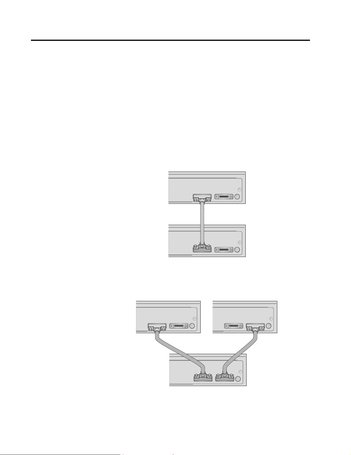
Stack of Two or
Three Switches
Creating a stack of two or three Ethernet switches requires no
additional hardware other than the AT-CABLE-4 cable that comes
with the switches. Figure 2-1 illustrates two Ethernet switches that
have been interconnected through the stacking ports to form a
logical switch.
IS-A IS-B
IS-A IS-B
STACK ID
STACK ID
2
0
1
Figure 2-1 Stack of Two Ethernet Switches
Creating a stack of three switches also does not require any
additional hardware, as illustrated in Figure 2-2.
IS-A IS-B
STACK ID
0
2
IS-A IS-B
IS-A IS-B
STACK ID
0
1
Figure 2-2 Stack of Three Ethernet Switches
STACK ID
0
3
31
Page 32

Planning the Installation
Stack of Four to
Eight Switches
In order to create a stack of from four to eight AT-8316F or AT-8324
Ethernet switches, you need the optional AT-Stack8 Stacking Matrix
Module (show in Figure 2-3). This module has eight ports, each
providing two gigabits of full-duplex bandwidth. Each stack requires
only one stacking module. You install the module into one of the
switches of the stack and then connect all of the switches to the
module using the AT-CABLE-4 cables.
8
K
C
A
T
-S
T
A
1
S
T
R
O
P
K
C
A
T
S
6
2
7
3
8
4
A
-
IS
5
D
I
K
C
A
T
S
B
-
IS
Figure 2-3 AT-Stack8 Stacking Matrix Module
32
Page 33

Expansion Modules
AT-8316F and AT-8324 Installation Guide
If you are building a stack of Ethernet switches, it is important to
know that the more switches in the stack, the fewer number of
expansion modules allowed. (This relates to the number of device
identification numbers that are available to the switches.)
Table 2-2 lists the number of expansion modules that you can install
in stacks of one to eight switches. For example, for a stack of six
switches you could install a total of eight expansion modules. The
expansion modules themselves can be installed in any switch in a
stack, and in any order.
Table 2-2 Permitted Number of Expansion Modules
Number of Switches
in the Stack
Total Number of
Expansion Slots in
the Stack
Permitted Number of
Expansion Modules
122
244
366
488
51010
6128
7144
8160
33
Page 34

Planning the Installation
Table 2-3 contains the cabling specifications for the expansion
modules.
Table 2-3 Expansion Module Cabling Specifications
Model Type of Cabling
1
Maximum Distance
AT-A15/SX 50/125 micron multimode fiber 550 meters2 (1,804 feet)
62.5/125 micron multimode fiber 275 meters (902 feet)
3
AT-A15/LX 9/125 micron single-mode fiber 10 kilometers (6.2 miles)
50/125 micron or 62.5/125 micron
550 meters (1,804 feet)
multimode fiber
AT-A16 50/125 micron or 62.5/125 micron
multimode fiber
Full-duplex:
2 kilometers (1.25 miles)
Half-duplex:
412 miles (1,351 feet)
AT-A17 50/125 micron or 62.5/125 micron
multimode fiber
Full-duplex:
2 kilometers (1.25 miles)
Half-duplex:
412 meters (1,351 feet)
2
AT-A18 10Base-T operation:
Category 3 or better
100Base-TX operation:
Category 5 or better
AT-A19 50/125 micron or 62.5/125 micron
multimode fiber
1. Refer to the IEEE 802.3 Standard for additional cable information.
2. Assumes a fiber optic cable rating of 500 Mhz/Km.
3. Assumes a fiber optic cable rating of 200 Mhz/Km
100 meters (328 feet)
100 meters (328 feet)
Full-duplex:
2 kilometers (1.25 miles)
Half-duplex:
412 meters (1,351 feet)
34
Page 35

Port Trunking
AT-8316F and AT-8324 Installation Guide
As explained in Chapter 1, port trunking, also referred to as “link
aggregation,” is an economical way for you to increase the
bandwidth between an AT-8316F or AT-8324 switch and another
network device, such as a server, router, workstation, or another
switch. A port trunk is two or more data ports that have been
grouped together to increase the bandwidth between a switch and a
network node. This increase in bandwidth can prove useful in
situations where a single connection between the switch and
another node is insufficient to handle the traffic load.
When ports are trunked together, they act as one logical path. The
increase in bandwidth is equal to the port speed times the number of
ports trunked together. For example, if you were to trunk together
four 100 Mbps ports, the result would be 400 Mbps of bandwidth.
The AT-8316F and AT-8324 switches allow you to trunk together two,
four, or eight ports, providing 200 Mbps, 400 Mbps, or 800 Mbps of
throughput. You can also trunk the ports on an expansion module to
increase the bandwidth from an expansion module to another
network device.
Guideline 1:
Number of
Ports in a Trunk
Guideline 2:
Using Ports
from the Same
Group
When implementing a port trunk, you will need to observe the
following guidelines:
The number of ports in a port trunk must be 2, 4, or 8 ports.
The ports on the Ethernet switches are divided into groups. When
choosing ports for a port trunk, the selected ports must be members
of the same group. You cannot create a port trunk consisting of ports
from different groups.
The ports on an AT-8324 switch are divided into five groups, as
illustrated in Figure 2-4.
10BASE-T / 100BASE-TX
FAST ETHERNET SWITCH
Group D
Group E
A
1X 3X 5X 7X
B
2X 4X 6X 8X
Group A
Ports 1 to 8
10BASE-T / 100BASE-TX
9X 11X 13X 15X
10X 12X 14X 16X
Group B
Ports 9 to 16
17X 19X 21X 23X
18X 20X 22X 24X
Group C
Ports 17 to 24
PORT ACTIVITY
L/A
100M LINK / ACTIVITY 10M LINK / ACTIVITY
D/C
HALF DUP/
FULL DUP
1234567891011121314151617181920212223
L/A
D/C
L/A
D/C
COL
STATUS
RS-232
TERMINAL PORT
FAULT
MASTER
RPS
PWR
24
RESET
Figure 2-4 Port Groupings on an AT-8324 Switch
35
Page 36

Planning the Installation
The ports on the AT-8316/MT and AT-8316/VF switches are divided
into four groups, as shown in Figure 2-5.
100BASE-FX FAST ETHERNET SWITCH
A
L/A
L/A
L/A
L/A
L/A
D/C
D/C
B
1 2 3 4 5 6 7 8 9 10 11 12 13 14 15 16
D/C
D/C
D/C
100BASE-FX
L/A
L/A
L/A
L/A
L/A
L/A
D/C
D/C
D/C
D/C
D/C
D/C
L/A
L/A
L/A
D/C
D/C
PORT ACTIVITY
L/A
ACTIVITY
100M LINK
D/C
FULL DUP
HALF DUP/ COL
L/A
L/A
D/C
D/C
D/C
RS-232
TERMINAL PORT
STATUS
FAULT
MASTER
RPS
PWR
RESET
Group C
Group D
Group A
Ports 1 to 8
Group B
Ports 9 to 16
Figure 2-5 Port Groups on an AT-8316F/MT or AT-8316/VF Switch
The ports on the AT-8316/SC switch also are divided into four
groups, as shown in Figure 2-6.
Group A
Ports 1 to 8
Group C
Group D
A
B
100BASE-FX FAST ETHERNET SWITCH
L/A
D/C
L/A
D/C
L/A
D/C
L/A
D/C
100BASE-FX
L/A
L/A
D/C
D/C
L/A
L/A
D/C
D/C
Group B
Ports 9 to 16
87654321
L/A
L/A
L/A
D/C
D/C
L/A
L/A
D/C
D/C
L/A
D/C
D/C
RXTXRXTXRXTXRXTXRXTXRXTXRXTXRXTX
161514131211109
L/A
L/A
D/C
D/C
RXTXRXTXRXTXRXTXRXTXRXTXRXTXRXTX
L/A
LINK / ACTIVITY
FULL DUP /
D/C
HALF DUP
COL
TERMINAL PORT
FAULT
MASTER
RPS
PWR
RESET
STATUS
RS-232
PORT ACTIVITY
Figure 2-6 Port Groups on an AT-8316F/SC Switch
As mentioned previously, the ports for a port trunk must be
members of the same group. A port trunk cannot consist of ports
from different groups. For example, you could use ports 4 and 5 on
an AT-8324 switch as one port trunk, and this would be valid since
the ports are members of the same group. However, ports 7, 8, 9, and
10 cannot be combined to form one port trunk on an AT-8324 switch
because these ports belong to different groups.
Guideline 3:
Creating Only
One Trunk Per
Group
Guideline 4:
Using
Consecutive
Ports
36
Each group of ports on an Ethernet sw itch can suppo rt only one po rt
trunk. For example, the AT-8324 Ethernet switch has three port
groups, assuming no expansion modules. Consequently, this switch
can support three port trunks, one port trunk for each port group.
The addition of two expansion modules would enable the switch to
support two additional port trunks, one for each module.
The ports of a trunk must be consecutive. For example, you could use
ports 4, 5, 6, and 7 as one port trunk, and this would be valid because
the ports are consecutive. However, an invalid selection of ports for a
trunk would be 1, 3, 5, and 7 since these ports are not consecutive.
Page 37

AT-8316F and AT-8324 Installation Guide
Guideline 5:
Cabling Based
on Port Number
Guideline 6:
Using
Expansion
Modules
When cabling a trunk, it is important that the order of the
connections be identical on both nodes. The lowest numbered port
in a trunk must be connected to the lowest numbered port on the
trunk on the other device, the next lowest numbered port must be
connected to the next lowest numbered port on the other device,
and so on.
For example, assume that you were installing a trunk from an
AT-8316F/SC switch to an AT-8324 switch. On the AT-8316F/SC
switch you had decided to use ports 12, 13, 14, 15 from port group
two for the trunk. On the AT-8324 switch you had chosen ports 21,
22, 23, and 24 from port group 3. To maintain the order of the port
connections, you would connect port 12 on the AT-8316F/SC switch
to port 21 on the AT-8224XL, port 13 to port 22, and so on.
Expansion modules also support port trunking. That is, you can
group the ports on an expansion module together to increase the
bandwidth to the end-node, whether that happens to be another
switch, a server, or router. Table 2-4 lists the number of port trunks
that you can create for each expansion module.
Table 2-4 Trunked Ports on Expansion Modules
Model of Expansion Module Trunked Ports
AT-A15 (SX or LX) 0
AT-A16 2 ports
AT-A17 2 ports
AT-A18 2 or 4 ports
AT-A19 2 ports
37
Page 38

Planning the Installation
Where to Go Next
Go to Chapter 3 for instructions on how to install the switch as a
standalone unit or as part of a stack.
38
Page 39

Chapter 3
Installing the Switch
This chapter describes the following installation procedures:
# Verifying the Package Contents
# Reviewing Safety Precautions
# Selecting a Site for the Switch
# Installing the Switch as a Standalone Unit
# Installing the Switch in a Rack
# Building a Stack of Two Switches
# Building a Stack of Three Switches
# Building a Stack of Four to Eight Switches
# Setting Up a Terminal for Local Management
# Modifying an Existing Stack
# Installing an Expansion Module
39
Page 40

Installing the Switch
Verifying the Package Contents
Make sure the following hardware components are included in your
switch package. If any of the following items are missing or
damaged, contact your Allied Telesyn sales representative.
# One AT-8316F/MT, AT-8316F/VF, AT-8316F/SC, or AT-8324
switch
# Two mounting brackets
# Six flathead Phillips screws
# Power cord (Americas, EC, Australia, and UK only)
# One AT-CABLE-4 cable
# One AT-8316F/MT, AT-8316F/VF, AT-8316F/SC, and AT-8324
Quick Install Guide
# Warranty card
40
Page 41

Reviewing Safety Precautions
Please review the following safety precautions before you begin to
install the switch in your network. Refer to Appendix A for translated
safety statements in your language.
Laser
Class 1 laser product. " 6
Laser
Do not stare into the laser beam. " 7
Caution
Electric Shock Hazard: To prevent electric shock, do not remove
the cover. There are no user-serviceable parts inside. The unit
contains hazardous voltages and should only be opened by a
trained and qualified technician. " 8
Caution
Lightening Danger: Do not work on this equipment or cables
during periods of lightening activity. " 9
AT-8316F and AT-8324 Installation Guide
Caution
Power cord is used as a disconnection device: To de-energize
equipment, disconnect the power cord. " 10
Caution
Electrical-Type Class 1 Equipment: This equipment must be
earthed. The power plug must be connected to a properly wired
earth ground socket outlet. An improperly wired socket outlet
could place hazardous voltages on accessible metal parts. " 11
Caution
Pluggable Equipment: The socket outlet should be installed near
the equipment and should be easily accessible. " 12
Caution
Air vents: The air vents must not be blocked on the unit and must
have free access to the room ambient air for cooling. " 13
Caution
Operating Temperature: This product is designed for a maximum
ambient temperature of 40°C. " 14
Caution
All Cou ntries: Install this product in accordance with local and
National Electric Codes. " 15
41
Page 42

Installing the Switch
Selecting a Site for the Switch
Be sure to observe the following requirements when choosing a site
for your switch:
# Make sure that the switch’s power is accessible and cables can
be connected easily.
# Cabling must be away from sources of electrical noise such as
radios, transmitters, broadband amplifiers, power lines,
electric motors, and fluorescent fixtures.
# Air flow around the switch and through its vents on the side
and rear must not be restricted.
# If you are installing the switch on a desk, make sure it is placed
on a level, secure desktop.
# Do not place objects on top of the switch.
# Do not expose the switch to moisture or water.
# Make sure it is in a dust-free environment.
# Use dedicated power circuits or power conditioners to supply
reliable electrical power to the network devices.
Having selected a site to install the switch, go to one of the following
procedures:
# Installing the Switch as a Standalone Unit on page 3-43
# Building a Stack of Two Switches on page 3-46
# Building a Stack of Three Switches on page 3-49
# Building a Stack of Four to Eight Switches on page 3-52
42
Page 43

Installing the Switch as a Standalone Unit
This section contains the procedure for installing an AT-8316F or
AT-8324 switch as a standalone unit (not as part of a stack). To install
the switch as a standalone unit, perform the following steps:
1. Remove all components from their shipping package and store
the packaging material in a safe location.
2. Locate a level, secure surface for the switch.
3. If you purchased an expansion module for a switch, install the
module by performing the procedure Installing an Expansion
Module on page 3-60.
4. If you want to install the switch in a rack, perform the procedure
Installing the Switch in a Rack on page 3-45.
5. Apply AC power to the switch by plugging the power cord into
the AC power connector on the back panel of the unit (shown in
Figure 3-1) and plugging the other end into a wall outlet.
AT-8316F and AT-8324 Installation Guide
IS-A IS-B
IS-A IS-B
R.P.S. Input Connector
AC Power Connector
Figure 3-1 AT-8316F and AT-8324 Ethern et Switch Rear Panel
Caution
The power cord is used as a disconnect device. To de-energize
equipment, disconnect the power cord. "10
STACK ID
STACK ID
0
0
43
Page 44
Installing the Switch
As power is applied to the switch, the Fault LED (shown in
Figure 3-2) flashes as the switch runs a series of internal self
tests. After the switch has finished running its self tests, the
Fault LED will stop flashing and will remain OFF.
RS-232
TERMINAL PORT
STATUS
FAULT
MASTER
RPS
PWR
Fault LED
RESET
Figure 3-2 Fault LED
For information on all the switch LEDs, refer to the section
Switch LEDs on page 1-16.
6. If you purchased a redundant power supply (RPS) unit for the
Ethernet switch, connect the RPS unit to the R.P.S. Input
connector on the rear of the switch by following the directions
included with the RPS system.
Caution
If you intend to use a redundant power supply (RPS) with the
switch, check to be sure that the cable with the RPS unit is
compatible with the RPS Input Port on the switch. The pin
assignments for the port are provided in Appendix B.
44
7. Connect the data cables to the ports on the switch.
8. Go to the procedure Setting Up a Terminal for Local
Management on page 3-59 to access the Omega management
software on the switch.
Page 45

Installing the Switch in a Rack
To install the Ethernet switch in a standard 19-inch rack, perform the
following steps:
1. Remove all components from the shipping package and store the
packaging material in a safe location.
2. Locate a level, secure surface for the switch.
3. Remove the snap-on plastic feet from the bottom of the switch, as
shown in Figure 3-3.
AT-8316F and AT-8324 Installation Guide
Figure 3-3 Removing the Feet
4. Attach the rackmounting brackets to each side of the switch,
using the six flathead screws that came in the switch package as
shown in Figure 3-4.
M
IR
R
O
R
P
O
R
T
LINK
X
R
S
T
-2
E
R
3
2
M
IN
A
L
P
O
R
T
S
T
A
T
U
S
F
A
U
L
T
M
A
S
T
E
R
R
P
S
P
W
R
R
E
S
E
T
Figure 3-4 Attaching Rackmounting Brackets
Caution
Air vents must not be blocked and must have free access to the
room ambient air for cooling. " 13
5. Mount the switch in the rack using standard screws (not
provided).
45
Page 46

Installing the Switch
Building a Stack of Two Switches
To build a stack of two switches, perform the following steps:
1. Select one of the Ethernet switches to be the master switch of the
stack. The other switch will be slave switch. In selecting the master
switch, follow these guidelines:
# The master switch can be either an AT-8316F or AT-8324
switch.
# If the two switches have different versions of the AT-S25 agent
software, select the switch that has the most recent version of
the AT-S25 software as the master switch.
Note
During network operations, the master switch will overwrite the
AT-S25 software in the slave switches with its own version of the
management software. This occurs even if a slave switch contains a
more recent version of the AT-S25 software. For this reason, it is
important that the switch you select to be the master switch have
the most recent version of the management software of all the
switches in the stack.
2. Remove all components from the shipping package and store the
packaging material in a safe location.
3. Locate a level, secure surface for the switches.
Note
If you are building a stack from existing AT-8316F and AT-8324
switches, power OFF the Ethernet switches. If the switches are
connected to an AT-RPS8000 redundant power supply unit, power
OFF the AT-RPS8000 unit using the ON/OFF switch on the back
panel of the unit.
4. If you purchased expansion modules for the switches, install the
modules by followin g the instruction s in the section Installing an
Expansion Module on page 3-60.
5. To install the switches in a rack, perform the procedure Installing
the Switch in a Rack on page 3-45.
6. Connect an AT-CABLE-4 cable between the IS-A ports on the back
panel of the master and slave switches.
46
Page 47

AT-8316F and AT-8324 Installation Guide
Figure 3-5 illustrates a stack of two switches connected with
one AT-CABLE-4 cable between Port IS-A on the master switch
and Port IS-A on the slave switch.
Slave switch
Master switch
Port IS-A
Port IS-A
IS-A IS-B
IS-A IS-B
STACK ID
STACK ID
2
0
1
Figure 3-5 Stack of Two Switches with One AT-Cable-4 Cable
Figure 3-6 illustrates an invalid cabling configuration for a
stack of two switches.
IS-A IS-B
STACK ID
0
2
IS-A IS-B
STACK ID
0
1
Figure 3-6 Invalid Cabling Configuration for a Stack of Two Switches
47
Page 48

Installing the Switch
STACK ID
1
7. Set the Stack ID switch on the master switch to 1. Refer to Figure
3-7.
IS-A IS-B
STACK ID
0
Figure 3-7 Stac k ID Switch
8. Set the Stack ID switch on the slave switch to 2.
9. Connect the data cables to the ports on the front of each switch.
10. Go to the procedure Powering On a Stack on page 3-57.
48
Page 49

Building a Stack of Three Switches
To build a stack of three switches, perform the following steps:
1. Select one of the Ethernet switches as the master switch of the
stack. The other two switches will be slave switches. In selecting
the master switch, follow these guidelines:
# The master switch can be either an AT-8316F or AT-8324
switch.
# If the switches have different versions of the AT-S25 agent
software, select the switch that has the most recent version of
the AT-S25 software as the master switch.
Note
During network operations, the master switch will overwrite the
AT-S25 software in the slave switches with its own version of the
management software. This occurs even if a slave switch contains a
more recent version of the AT-S25 software. For this reason, it is
important that the switch you select to be the master switch have
the most recent version of the management software of all the
switches in the stack.
AT-8316F and AT-8324 Installation Guide
2. Remove all components from the shipping package and store the
packaging material in a safe location.
3. Locate a level, secure surface for the switches.
Note
If you are building a stack from existing AT-8316F and AT-8324
switches, power OFF the Ethernet switches. If the switches are
connected to an AT-RPS8000 redundant power supply unit, power
OFF the AT-RPS8000 unit using the ON/OFF switch on the back
panel of the unit.
4. If you purchased expansion modules for the switches, install the
modules by performing the procedure Installing an Expansion
Module on page 3-60.
5. To install the switches in a rack, perform the procedure Installing
the Switch in a Rack on page 3-45.
49
Page 50

Installing the Switch
6. Connect one AT-CABLE-4 cable between the IS-A ports on the
master switch and a slave switch, and another AT-CABLE-4 cable
between the IS-B ports on the master switch and the other slave
switch. Refe r t o Figure 3-8 .
Slave
switch
Port IS-A
IS-A IS-B
STACK ID
0
2
IS-A IS-B
STACK ID
0
Slave
switch
3
Port IS-B
Master switch
IS-A IS-B
Port IS-A
STACK ID
0
1
Port IS-B
Figure 3-8 Valid Cabling Configuration for a Stack of Three Switches
Note
A stack of three switches can have only one cable between the
switches.
Figure 3-9 illustrates an invalid cabling configuration for a
stack of three switches.
IS-A IS-B
STACK ID
0
IS-A IS-B
IS-A IS-B
STACK ID
0
STACK ID
0
Figure 3-9 Invalid Cabling Configurations for a Stack of Three Switches
50
Page 51

AT-8316F and AT-8324 Installation Guide
7. Set the Stack ID switch on the master switch to 1. Refer to Figure
3-7 for the location of the Stack ID switch.
8. Set the Stack ID switch on one slave switch to 2 and set the Stack
ID switch on the other slave switch to 3.
Note
Do not use a setting of 0 (zero) or 9. These settings are invalid.
9. Connect the data cables to the ports on the front of each switch.
10. Go to the procedure Powering On a Stack on page 3-57.
51
Page 52

Installing the Switch
Building a Stack of Four to Eight Switches
To build a stack of four to eight Ethernet switches with the optional
AT-Stack8 Stacking Matrix Module, perform the following steps:
1. Select an AT-8316F or AT-8324 Ethernet switch in which to install
the AT-Stack8 module. This switch will be referred to as the master
switch. The other switches in the stack will be referred to as slave
switches. In selecting the master switch, observe the following
guidelines:
# The AT-Stack8 module can be installed in either an AT-8316F
or AT-8324 switch, even in stacks that will consist of a
combination of AT-8316F and AT-8324 switches.
# If the Ethernet switches have different versions of the AT-S25
software, install the module into the switch that has the most
recent version of the software.
Note
During network operations, the master switch will overwrite the
AT-S25 software in the slave switches with its own version of the
management software. This occurs even if a slave switch contains a
more recent version of the AT-S25 software. For this reason, it is
important that the switch you select to be the master switch have
the most recent version of the management software of all the
switches in the stack.
2. Remove all components from the shipping package and store the
packaging material in a safe location.
3. Locate a level, secure surface for the switches.
Note
If you are building a stack from existing AT-8316F and AT-8324
switches, power OFF all the Ethernet switches that will be a part of
the stack. If the switches are connected to an AT-RPS8000
redundant power supply unit, power OFF the AT-RPS8000 unit
using the ON/OFF switch on the back panel of the unit.
4. If you purchased optional expansion modules for the switches,
install the modules by performing the procedure Installing an
Expansion Module on page 3-60.
52
5. To install the switches in a rack, perform the procedure Installing
the Switch in a Rack on page 3-45.
Page 53

AT-8316F and AT-8324 Installation Guide
6. Remove the blank panel from the back of the switch selected to
be the master switch by unscrewing the two captive screws. Refer
to Figure 3-10.
K ID
C
STA
-B
IS
-A
IS
Captive screw
Captive screw
Figure 3-10 Removing the Blank Panel from an Ethernet Switch
7. Remove the AT-Stack8 module from its shipping package and
store the packaging material in a safe location.
8. Slide the AT-Stack8 module into the expansion slot making sure
that the board is aligned properly with the card guides. Slide the
board into the switch until it snaps into place. Refer to Figure 3-11.
Card Guide
5
AT-STAC K8
4
3
-A
2
1
S
T
R
O
P
K
C
A
T
S
7
6
IS
8
ID
K
C
A
T
S
-B
IS
Captive screws
Figure 3-11 Installing the AT-Stack8 Module
9. Secure the AT-Stack8 module by tightening the two captive
screws.
10. Connect one end of an AT-CABLE-4 cable to Port 1 on the
AT-Stack8 module and the other end to Port IS-A on the master
switch. Refer t o Fi g ure 3- 12.
53
Page 54

Installing the Switch
Note
Port 1 on the stacking module must be connected to Port IS-A on
the master switch.
Port 1
AT-STA CK8
STACK PORTS
1
6
2
7
3
8
4
IS-A
IS-A IS-B
5
STACK ID
STACK ID
IS-B
Port IS-A
Figure 3-12 Cabling the Master Switch with an AT-CABLE-4 Cable
11. Connect the slave switches to the stacking module using
additional AT-CABLE-4 cables. When connecting an AT-CABLE-4
cable to a switch, be sure to connect it to the IS-A port on the back
of the switch rather than the IS-B port.
0
0
54
Page 55

Slave switch #1
(Stack ID 2)
Slave switch #2
(Stack ID 3)
Master switch
(Stack ID 1)
AT-8316F and AT-8324 Installation Guide
Figure 3-13 illustrates an example of a stack of five switches.
STACK ID
STACK ID
0
0
STACK ID
STACK ID
0
0
5
STACK ID
STACK ID
IS-B
0
0
AT-STAC K8
STACK PORTS
IS-A IS-B
IS-A IS-B
IS-A IS-B
IS-A IS-B
1
6
2
7
3
8
4
IS-A IS-B
IS-A
Slave switch #3
(Stack ID 6)
Slave switch #4
(Stack ID 7)
IS-A IS-B
IS-A IS-B
IS-A IS-B
IS-A IS-B
Figure 3-13 Example of a Stack of Five Switches
STACK ID
STACK ID
STACK ID
STACK ID
0
0
0
0
55
Page 56

Installing the Switch
12. Set the Stack ID switch on the master switch to 1. Refer to Figure
3-7 for the location of the Stack ID switch.
Note
The Stack ID switch on the master switch must be set to 1.
13. Set the Stack ID switch on each slave switch to match the port
number on the AT-Stack8 module to which the Ethernet switch is
connected.
For example, referring to the stack example in Figure 3-13, the
Stack ID setting for slave switch #1 would be 2 because it is
connected to port 2 on the AT-Stack8 module. The Stack ID
setting for slav e switch #2 woul d be 3 it is connec ted to port 3
on the AT-Stack8 module. The Stack ID numbers for slave
switch #3 would be 6 and the Stack ID setting for slave switch
#4 would be 7.
Note
Do not use the Stack ID settings of 0 (zero) or 9 for any switch in a
stack. These settings are invalid.
14. Connect the data cables to the ports on the front of each switch.
15. Go to the procedure Powering On a Stack on page 3-57.
56
Page 57

Powering On a Stack
To power on an Ethernet stack, perform the following procedure:
1. Apply AC power to each slave and master switch in the stack by
AT-8316F and AT-8324 Installation Guide
plugging a power cord into the AC power connector on the back
panel of the switch (shown in Figure 3-1) and plugging the other
end into a wall outlet.
To simplify the process, you can connect all of the switches,
both master and slaves, to the same power circuit, such as a
power strip, and so be able to apply power to all of the
switches at the same time. If you power ON the switches
individually, you should apply power to the slave switches
first, and then the master switch.
Caution
The power cord is used as a disconnect device. To de-energize
equipment, disconnect the power cord. "10
As power is applied to a switch, the Fault LED (shown in Figure
3-14) flashes as a series of internal self tests are performed and
as the hardware is configured. Wait for the Fault LED to stop
flashing and remain OFF.
RS-232
TERMINAL PORT
STATUS
FAULT
MASTER
RPS
PWR
Fault LED
RESET
Figure 3-14 Fault LED
For further information on the switch LEDs, refer to the section
Switch LEDs on page 1-16.
2. Wait while the master switch performs the topology discovery
process. The master switch performs the process in order to
determine the number and types of switches that are in the stack.
During the discovery process, which takes less than one minute to
complete, the port LEDs on each switch will flash in sequence, the
slave switches first and the master switch last.
57
Page 58

Installing the Switch
3. If you purchased a redundant power supply (RPS) unit for the
Ethernet switches, connect the RPS unit to the R.P.S. Input
connectors on the rear of the switch by following the directions
included with the RPS system.
Caution
If you intend to use a redundant power supply (RPS) with the
switch, check to be sure that the cable with the RPS unit is
compatible with the RPS Input Port on the switch. The pin
assignments for the port are provided in Appendix B.
4. Go to the next procedure, Setting Up a Terminal for Local
Management on page 3-59, to access the Omega management
software on the switch.
58
Page 59

Setting Up a Terminal for Local Management
If you are installing the switch in a TCP/IP environment or if you
intend to manage the switch from a remote site, you must first assign
an IP address to the switch using the Omega management interface,
which comes p re-installed on the switch. This is accomplished by
connecting a terminal (such as a VT100 terminal) or a PC with a
terminal emulation program to the RS232 port on the master switch,
as explained in the following steps:
1. Using an RS232, DB-9 straight-through cable, connect a terminal
or a PC with a terminal emulation program to the RS232
connector on the front panel of the master switch.
Note
Only the RS232 port on the master switch of a stack is active. The
RS232 ports on the slave switches are inactive and cannot be used
to manage a stack.
2. Configure the terminal or the terminal emulation program to the
following settings:
AT-8316F and AT-8324 Installation Guide
# Baud rate: 9600
# Data bits: 8
# Parity: None
# Stop bits: 1
# Flow control: None
3. Press Return.
The switch displays the Omega main menu.
You are now ready to use the Omega management interface
to configure the switch. For instructions, refer to the AT-S25
Management Software User’s Guide. This guide is available
on the Allied Telesyn web site at www.alliedtelesyn.com/
techhome.htm.
59
Page 60

Installing the Switch
Installing an Expansion Module
This section contains the instructions for installing an optional
expansion module in a switch. For information on cabling
specifications for the expansion modules, refer to the section
Expansion Modules on page 2-33.
To install an expansion module, perform the following steps:
1. Disconnect the switch’s power cord, if attached.
Caution
Be sure to disconnect the power cord to the switch before installing
an expansion module. If the switch is connected to a redundant
power supply (RPS) unit, disconnect the switch from the RPS unit as
well. Installing the expansion module with the switch powered ON
can damage the module.
2. Remove a blank faceplate from one of the expansion slots on the
front of the switch by unscrewing the faceplates two captive
screws. Refer to Figure 3-15. Do not remove the blank faceplate if
you are not installing an expansion module in the slot.
A
B
Figure 3-15 Removing the Blank Panel
If you are installing only one expansion module in the switch,
install the module in slot A. While the module will work in slot
B with slot A empty, the port numbering assignments will
change if you later install a module in slot A. This could affect
VLAN memberships on the switch, and this could require you
to adjust your VLAN configurations.
60
Page 61

AT-8316F and AT-8324 Installation Guide
For example, if you install an AT-A17 in slot B of an AT-8324
switch while leaving slot A empty, the switch will assign the
port numbers 25 and 26 to the ports on the module. If you
later install another AT-A17 in slot A, the switch will
automatically reallocate port numbers 25 and 26 to the new
module in slot A and assign the port numbers 27 and 28 to the
module in slot B. If the module in slot B had been a member of
a VLAN, you would be required to reconfigure the VLAN to
reflect the change to its port numbers.
3. Remove the expansion module from the packing material.
4. Slide the expansion module into the empty slot making sure the
board is aligned properly with the card guides. Refer to Figure
3-16.
L
IN
K
F
U
L
L D
U
P
H
A
L
F D
U
P
Card Guide
A
C
T
IV
IT
Y
1
T
X
C
O
L
A
T
-A
1
7
R
X
1
0
0
B
A
S
E
-F
A
2
C
T
IV
IT
Y
T
X
R
X
LIN
X
/S
C
K
F
U
L
L
D
U
P
C
O
L
H
A
LF
D
U
P
A
B
Figure 3-16 Installing an Expansion Module
5. Secure the expansion module to the switch by tightening the
captive screws.
6. Connect the cabling to the ports on the expansion module.
61
Page 62

Installing the Switch
Resetting a Stack
This section contains the procedure for resetting an AT-8316F or
AT-8324 switch stack.
Note
You cannot reset just one switch in a switch stack. You must reset
the entire stack.
To reset a stack, perform the following procedure:
1. Press the Reset button on the front panel of the slave switches.
2. Press the Reset button on the master switch.
Note
You should reset the slave switches first, before the master switch.
Each switch in the stack will perform a series of internal selftests, indicated by a flashing Fault LED (shown in Figure 3-2).
After a switch has finished running its self tests, the Fault LED
will stop flashing and will remain OFF.
3. Wait while the master switch performs the topology discovery
process. This process is used by the master switch to determine
the number and types of switches that constitute the stack.
During the discovery process, which takes less than one minute to
complete, the port LEDs on each switch will flash in sequence, the
slave switches first and the master switch last.
62
Page 63

Where to Go Next
AT-8316F and AT-8324 Installation Guide
Now that the switch is operational, you are ready to configure and
monitor it as explained in the AT-S25 Management Software
User’s Guide, which is available from Allied Telesyn’s web site at
www.alliedtelesyn.com/techhome.htm.
63
Page 64

Page 65

Chapter 4
Troubleshooting
This chapter provides information on how to detect and resolve
problems with your switch. This section includes the following
sections:
# At the First Sign of a Problem
# Network Cabling Problems
# Calling Technical Support
# How the Switch Reports Problems
# Common Problems
65
Page 66

Troubleshooting
At the First Sign of a Problem
Perform the following tasks when you first become aware of a
problem with the switch:
# Make sure the power cord is securely connected and the
power voltage is not fluctuating.
# Check the data cables for secure connections and make sure
the device at the other end of a connection is operational.
# Reset the stack so that the switches can run self-diagnostics.
For instructions, refer to the section Resetting a Stack on
page 3-62.
# Use Omega to read statistics and run diagnostics. Refer to the
AT-S25 Management Software User’s Guide for further
details on gathering Ethernet statistics and running
diagnostics using the Omega menus.
# If the management software has failed, check the LEDs to see
if the switch continues to forward packets. Then, at a
convenient time, reset the stack, as explained in the section
Resetting a Stack on page 3-62.
# If problems still persist, for example, the Fault LED remains ON,
call Allied Telesyn’s Technical Support or visit Allied Telesyn’s
web site at www.alliedtelesyn.com.
66
Page 67

Network Cabling Problems
If you have an AT-8324 switch, some network problems may be
related to exceeding cabling distances. Refer to the standard IEEE
802.3u, Clause 29.3.1. 2 o n Worst Case Path Delay Value. This
document specifies that the collision domain diameter must be
within the following limits:
# Under 100 meters (328 feet) for TX cabling
# Under 412 meters (1,332 feet) for half-duplex FX cabling
Calling Technical Support
When contacting Allied Telesyn for support on any of its products,
you will need to provide Technical Support with the following
information:
# Model and serial number
AT-8316F and AT-8324 Installation Guide
# Software version number
# Description of the problem
Refer to Allied Telesyn’s web site at www.alliedtelesyn.com
of worldwide locations.
for a list
67
Page 68

Troubleshooting
How the Switch Reports Problems
The switch detects and processes errors as follows:
# The LEDs indicate problems with the ports and power. Table
4-1 and Table 4-2 describe the switch LEDs.
# In a TCP/IP environment, if you have configured the software
correctly, the management software triggers an SNMP trap
message. As a result, the software then sends traps to alert the
network manager when a trigger occurs. This type of software
configuration allows the network administrator to proactively
monitor the network.
T able 4-1, Table 4-2, and Table 4-3 list and describe the switch
and expansion module LEDs. As power is applied to the
switch, the Fault LED flashes as the switch runs internal self
tests.
Table 4-1 Switch System LED Status
LED State Description
Fault Solid Red The switch or management software is malfunctioning.
Flashing Red The switch is booting, running diagnostic tests, writing
messages to FLASH, or transferring files using XMODEM.
Off Normal operation.
Master Solid Amber The switch is functioning as the master switch for the
stack.
OFF The switch is a slave switch.
RPS (Redundant
Power Supply)
Solid Green The RPS is connected to the switch. To verify that the RPS
is operating correctly, refer to the instructions in the RPS
Quick Install Guide.
Power Solid Green The switch is receiving power, the voltage is within the
acceptable range, and the power supply is working.
68
Page 69

AT-8316F and AT-8324 Installation Guide
Table 4-2 Switch Port LED Status
LED State Description
L/A (Link/Activity) Solid Green This indicates a 100 Mbps link.
Flashing Green This indicates 100 Mbps activity.
Solid Amber This indicates a 10 Mbps link. (10/100 ports only)
Flashing Amber This indicates 10 Mbps activity. (10/100 ports only)
D/C (Duplex/Collision) Solid Green The port is operating at full duplex.
Solid Amber The port is operating at half duplex.
Flashing Amber Collisions are occurring on the line.
Table 4-3 describes the LEDs on the optional expansion modules.
Table 4-3 Expansion Module Port LED Status
LED State Description
L/A (Link/Activity) Solid Green This indica tes a 100 Mbps link.
Flashing Green This indicates 100 Mbps activity.
Solid Amber This indicate s a 10 Mbps link (AT-A18 module
only).
Flashing Amber This indicates 10 Mbps activity (AT-A18 modu le
only).
D/C (Duplex/Collision) Solid Green The port is operating at full-duplex.
Solid Amber The port is operating at half-duplex.
Flashing Amber Collisions are occurring on the line.
69
Page 70

Troubleshooting
Common Problems
This section lists common possible sources of error and actions
required to correct them.
Link /Activity
LED on Any
Port is OFF
This can indicate:
# A loose data cable.
# The device at the other end of the connection is turned OFF.
# The data cable is not wired correctly (straight/crossed) for the
device.
# The network administrator manually disabled the port
through the software.
# The port’s selected transmission mode does not match that of
the attached device.
Perform the following steps in sequence; you need not proceed to
the next step if the problem is resolved:
1. Make sure the data cables are secure.
2. Make sure the device at the end of the connection is turned ON.
3. Make sure the data cable is wired correctly (straight/crossed) for
the device.
4. Logon to Omega if you can and check the port status (Port
status and configuration><port number>
If the port is Enabled, make sure the transmission speed
matches that of the connected device (auto-negotiating, fullor half-duplex).
Refer to the AT-S25 Management Software User’s Guide to
check that the port is Disabled. If the port is Disabled,
someone has manually disabled the port through the
software for a specific reason. Verify that the reason no longer
exists before you enable this port (
configuration
5. Contact Allied Telesyn’s Technical Support for help.
).
Port status and
menu).
70
Page 71

AT-8316F and AT-8324 Installation Guide
Power LED is
OFF
If there is no power to the switch, it cannot function.
A Power LED that is OFF can indicate:
# A loose power cord.
# Power supply failure, malfunction, or loss of power to the
power supply.
# A power supply voltage below acceptable levels.
# A high switch temperature due to fan failure or extreme
ambient temperature.
Perform the following steps in sequence; you need not proceed to
the next step if the problem is resolved:
1. Secure the power cord to the power source and check the Power
LED to see if it is ON.
2. Ensure that the voltage is within the required levels in your region.
3. Logon to Omega and run Diagnostics if you can
(Administration>Diagnostics) and record any failures.
4. Contact Allied Telesyn’s Technical Support and report the results
of the tests.
Fault LED is ON This might indicate problems with the network management
software, such as:
# An unsuccessful software do wnload
# A failure of the power-on diagnostics
Perform the following steps in sequence; you need not proceed to
the next step if the problem is resolved:
1. Reset the stack either by:
—Pressing the RESET button on the front panel of the
switches in the stack, or
—Selecting
the system
2. Make sure the RS-232 connection from the local terminal or PC to
the master switch is secure; change the cable if necessary.
Administration>Reset and restart
from Omega, if you can.
If you cannot access the switch locally because of a faulty
RS-232 connection, try to access the switch through a web
browser or remotely with Telnet or an SNMP network
management program until the problem is fixed.
71
Page 72

Troubleshooting
3. Unplug the switch from the power source, then plug it back in
again.
4. Try to log on to Omega and run diagnostics
(Administration>Diagnostics).
5. Download software using the Administration menu. Refer to
the AT-S25 Management Software User’s Guide that you
downloaded from www.alliedtelesyn.com/techhome.htm for
instructions.
6. Contact Allied Telesyn’s Technical Support for help.
72
Page 73

Appendix A
Translated Electrical Safety and Emission Information
IMPORTANT: This appendix contains multiple-language translations for
the safety statements in this guide.
WICHTIG: Dieser Anhang enthält Übersetzungen der in diesem
Handbuch enthaltenen Sicherheitshinweise in mehreren Sprachen.
VIGTIGT: Dette tillæg indeholder oversættelser i flere sprog af
sikkerhedsadvarslerne i denne håndbog.
BELANGRIJK: Deze appendix bevat vertalingen in meerdere talen van
de veiligheidsopmerkingen in deze gids.
IMPORTANT: Cette annexe contient la traduction en plusieurs langues
des instructions de sécurité figurant dans ce guide.
TÄRKEÄÄ: Tämä liite sisältää tässä oppaassa esiintyvät turvaohjeet
usealla kielellä.
IMPORTANTE: questa appendice contiene traduzioni in più lingue degli
avvisi di sicurezza di questa guida.
VIKTIG: Dette tillegget inneholder oversettelser til flere språk av
sikkerhetsinformasjonen i denne veiledningen.
IMPORTANTE: Este anexo contém traduções em vários idiomas das
advertências de segurança neste guia.
IMPORTANTE: Este apéndice contiene traducciones en múltiples
idiomas de los mensajes de seguridad incluidos en esta guía.
OBS! Denna bilaga innehåller flerspråkiga översättningar av
säkerhetsmeddelandena i denna handledning.
73
Page 74

Translated Electrical Safety and Emission Information
" 1 RFI Emission EN55022 Class A
" 2 WARNING: In a domestic environment this product may cause radio interference in which case
Standards: This product meets the following standards.
U.S. Federal Communications Commission
RADIATED ENERGY
Note: This equipment has been tested and found to comply with the limits for a Class A
digital device pursuant to Part 15 of the FCC Rules. These limits are designed to provide
reasonable protection against harmful interference when the equipment is operated in a
commercial environment. This equipment generates, uses, and can radiate radio frequency
energy and, if not installed and used in accordance with this instruction manual, may cause
harmful interference to radio communications. Operation of this equipment in a residential
area is likely to cause harmful interference in which case the user will be required to correct
the interference at his own expense.
Note: Modifications or changes not expressly approved by the manufacturer or the FCC can
void your right to operate this equipment.
Industry Canada
This Class A digital apparatus meets all requirements of the Canadian Interference-Causing
Equipment Regulations.
Cet appareil numérique de la classe A respecte toutes les exigences du Règlement sur le
matériel brouilleur du Canada.
the user may be required to take adequate measures.
" 3 Immunity EN50082-1 1997
" 4 Electrical Safety EN60950, UL 1950, CSA 950
" 5 Laser EN60825
SAFETY
" 6 WARNING: Class 1 Laser product.
" 7 WARNING: Do not stare into the laser beam.
" 8 ELECTRICAL N OTICES
WARNING: ELECTRIC SHOCK HAZARD
To prevent ELECTRIC shock , do not remove the cover. No user-serviceable parts inside. This
unit contains HAZARDOUS VOLTAGES and should only be opened by a trained and qualified
technician. To avoid the possibility of ELECTRIC SHOCK, disconnect electric power to the
product before connecting or disconnecting the LAN cables.
" 9 LIGHTNING DANGER
DANGER: DO NOT WORK on equipment or CABLES during periods of LIGHTNING ACTIVITY.
" 10 CAUTION: POWER CORD IS USED AS A DISCONNECTION DEVICE. TO DE-EN ERGIZE EQUIPMEN T,
disconnect the power cord.
" 11 ELECTRICAL - TYPE CLASS 1 EQUIPMENT
THIS EQUIPMENT MUST BE EARTHED. Power plug must be connected to a properly wired earth
ground socket outlet. An improperly wired socket outlet could place hazardous voltages on
accessible metal parts.
" 12 PLUGGABLE EQUIPMENT, the socket outlet shall be installed near the equipment and shall be
easily accessible.
74
" 13 CAUTION: Air vents must not be blocked and must have free access to the room ambient air
for cooling.
" 14 OPERATING TEMPER AT URE: T his p roduc t i s desi gned for a maxi mum a mbien t tem pera ture of
40° degrees C.
" 15 ALL COUNTRIES: Install product in accordance with local and National Electrical Codes.
Page 75
AT-8316F and AT-8324 Installation Guide
Normen: Dieses Produkt erfüllt die Anforderungen der nachfolgenden Normen.
" 1 Hochfrequenzstörung EN55022 Klasse A
" 2 WARNUNG: Bei Verwendung zu Hause kann dieses Produkt Funkstörungen hervorrufen. In
diesem Fall müßte der Anwender angemessene Gegenmaßnahmen ergreifen.
" 3 Störsicherheit EN50082-1 1997
" 4 Elektrische Sicherheit EN60950, UL 1950, CSA 950
" 5 Laser EN60825
SICHERHEIT
" 6 WARNUNG Laserprodukt der Klasse 1.
" 7 WARNUNG Nicht direkt in den Strahl blicken.
" 8 ACHTUNG: GEFÄHRLICHE SPANNUNG
Das Gehäuse nicht öffnen. Das Gerät enthält keine vom Benutzer wartbaren Teile. Das Gerät
steht unter Hochspannung und darf nur von qualifiziertem technischem Personal geöffnet werden.
Vor Anschluß der LAN-Kabel, Gerät vom Netz trennen.
" 9 GEFAHR DURCH BLITZSCHLAG
GEFAHR: Keine Arbeiten am Gerät oder an den Kabeln während eines Gewitters ausführen.
" 10 VORSICHT: DAS NETZKABEL DIENT ZUM TRENNEN DER STROMVERSORGUNG. ZUR TRENNUNG
VOM NETZ, KABEL AUS DER STECKDOSE ZIEHEN.
" 11 GERÄTE DER KLASSE 1
DIESE GERÄTE MÜSSEN GEERDET SEIN. Der Netzstecker darf nur mit einer vorschriftsmäßig
geerdeten Steckdose verbunden werden. Ein unvorschriftsmäßiger Anschluß kann die
Metallteile des Gehauses unter gefährliche elektrische Spannungen setzen.
" 12 STECKBARES GERÄT: Die Anschlußbuchse sollte in der Nähe der Einrichtung angebracht
werden und leicht zugänglich sein."
" 13 VORSICHT
Die Entlüftungsöffnungen dürfen nicht versperrt sein und müssen zum Kühlen freien Zugang
zur Raumluft haben.
" 14 BETRIEBSTEMPERATUR: Dieses Produkt wurde für den Betrieb in einer
Umgebungstemperatur von nicht mehr als 40° C entworfen.
" 15 ALLE LÄNDER: Installation muß örtlichen und nationalen elektrischen Vorschriften
entsprechen.
75
Page 76

Translated Electrical Safety and Emission Information
" 1 Radiofrekvens forstyrrelsesemission EN55022 Klasse A
Standarder: Dette produkt tilfredsstiller de følgende standarder.
" 2 ADVARSEL: I et hjemligt miljø kunne dette produkt forårsage radio forstyrrelse. Bliver det
tilfældet, påkræves brugeren muligvis at tage tilstrækkelige foranstaltninger.
" 3 Immunitet EN50082-1 1997
" 4 Elektrisk sikkerhed EN60950, UL 1950, CSA 950
" 5 Laser EN60825
SIKKERHED
" 6 ADVARSEL Laserprodukt av klasse 1.
" 7 ADVARSEL Stirr ikke på strålen.
" 8 ELEKTRISKE FORHOLDSREGLER
ADVARSEL: RISIKO FOR ELEKT R I SK ST Ø D
For at forebygge ELEKTRISK stød, undlad at åbne apparatet. Der er ingen indre dele, der kan
repareres af brugeren. Denne enhed indeholder LIVSFARLIGE STRØMSPÆNDINGER og bør kun
åbnes af en uddannet og kvalificeret tekniker. For at undgå risiko for ELEKTRISK STØD, afbrydes
den elektriske strøm til produktet, før LAN-kablerne monteres ell er afmonteres.
" 9 FARE UNDER UVEJR
FARE: UNDLAD at arbejde på udstyr eller KABLER i perioder med LYNAKTIVITET.
" 10 ADVARSEL: DEN STRØMFØRENDE LEDNING BRUGES TIL AT AFBRYDE STRØMMEN. SKAL
STRØMMEN TIL APPARATET AFBRYDES, tages ledningen ud af stikket.
" 11 ELEKTRISK - KLASSE 1-UDSTYR
DETTE UDSTYR KRÆVER JORDFORBINDELSE. Stikket skal være forbundet med en korrekt
installeret jordforbunden stikkontakt. En ukorrekt installeret stikkontakt kan sætte livsfarlig
spænding til tilgængelige metaldele.
" 12 UDSTYR TIL STIKKONTAKT, stikkontakten bør installeres nær ved udstyret og skal være
lettilgængelig.
" 13 ADVARSEL: Ventilationsåbninger må ikke blokeres og skal have fri adgang til den omgivende
luft i rummet for afkøling.
" 14 BETJENINGSTEMPERATUR: Dette apparat er konstrueret til en omgivende temperatur på
maksimum 40 grader C.
" 15 ALLE LANDE: Installation af produktet skal ske i overensstemmelse med lokal og national
lovgivning for elektriske installationer.
76
Page 77
AT-8316F and AT-8324 Installation Guide
Eisen: Dit product voldoet aan de volgende eisen.
" 1 RFI Emissie EN55022 Klasse A
" 2 WAARSCHUWING: Binnenshuis kan dit product radiostoring veroorzaken, in welk geval de
gebruiker verplicht kan worden om gepaste maatregelen te nemen.
" 3 Immuniteit EN50082-1 1997
" 4 Electrische Veiligheid EN60950, UL 1950, CSA 950
" 5 Laser EN60825
VEILIGHEID
" 6 WAARSHUWING Klasse-1 laser produkt.
" 7 WAARCHUWING Neit in de straal staren.
" 8 WAARSCHUWINGEN MET BETREKKING TOT ELEKTRICITEIT
WAARSCHUWING: GEVAAR VOOR ELEKTRISCHE SCHOKKEN
Verwijder het deksel niet, teneinde ELEKTRISCHE schokken te voorkomen. Binnenin bevinden
zich geen onderdelen die door de gebruiker onderhouden kunnen worden. Dit toestel staat
onder GEVAARLIJKE SPANNING en mag alleen worden geopend door een daartoe opgeleide en
bevoegde technicus. Om het gevaar op ELEKTRISCHE SCHOKKEN te vermijden, moet u het
toestel van de stroombron ontkoppelen alvorens de LAN-kabels te koppelen of ontkoppelen.
" 9 GEVAAR VOOR BLIKSEMINSLAG
GEVAAR: NIET aan toestellen of KABELS WERKEN bij BLIKSEM.
" 10 WAARSCHUWING: HET TOESTEL WORDT UITGESCHAKELD DOOR DE STROOMKABEL TE
ONTKOPPELEN.OM HET TOESTEL STROOMLOOS TE MAKEN: de stroomkabel ontkoppelen.
" 11 ELEKTRISCHE TOESTELLEN VAN KLASSE 1
DIT TOESTEL MOET GEAARD WORDEN. De stekker moet aangesloten zijn op een juist geaarde
contactdoos. Een onjuist geaarde contactdoos kan de metalen onderdelen waarmee de
gebruiker eventueel in aanraking komt onder gevaarlijke spanning stellen.
" 12 AAN TE SLUITEN APPARATUUR, de contactdoos wordt in de nabijheid van de apparatuur
geïnstalleerd en is gemakkelijk te bereiken."
" 13 OPGELET: De ventilatiegaten mogen niet worden gesperd en moeten de omgevingslucht
ongehinderd toelaten voor afkoeling.
" 14 BEDRIJFSTEMPERATUUR : De omgevingstemperatuur voor dit produkt mag niet meer
bedragen dan 40 graden Celsius.
" 15 ALLE LANDEN: het toestel installeren overeenkomstig de lokale en nationale elektrische
voorschriften.
77
Page 78
Translated Electrical Safety and Emission Information
" 1 Emission d’interférences radioélectriques EN55022 Classe A
Normes: ce produit est conforme aux normes de suivantes:
" 2 MISE EN GARDE : dans un environnement domestique, ce produit peut provoquer des
interférences radioélectriques. Auquel cas, l’utilisateur devra prendre les mesures adéquates.
" 3 Immunité EN50082 - 1 1997
" 4 Sécurité électrique EN60950, UL 1950, CSA 950
" 5 Laser EN60825
SÉCURITÉ
" 6 ATTENTION Producit laser di classe 1.
" 7 ATTENTION Ne pas fixer le faisceau des yeux.
" 8 INFORMATION SUR LES RISQUES ÉLECTRIQUES
AVERTISSEMENT: DANGER D’ÉLECTROCUTION
Pour éviter toute ÉLECTROCUTION, ne pas ôter le revêtement protecteur du matériel. Ce
matériel ne contient aucun élément réparable par l’utilisateur. Il comprend des TENSIONS
DANGEREUSES et ne doit être ouvert que par un technicien dûment qualifié. Pour éviter tout
risque d’ÉLECTROCUTION, débrancher le matériel avant de connecter ou de déconnecter les
câbles LAN.
" 9 DANGER DE FOUDRE
DANGER: NE PAS MANIER le matériel ou les CÂBLES lors d’activité orageuse.
" 10 ATTENTION: LE CORDON D’ALIMENTATION SERT DE MISE HORS CIRCUIT. POUR COUPER
L’ALIMENTATION DU MATÉRIEL, débrancher le cordon.
" 11 ÉQUIPEMENT DE CLASSE 1 ÉLECTRIQUE
CE MATÉRIEL DOIT ÊTRE MIS A LA TERRE. La prise de courant doit être branchée dans une prise
femelle correctement mise à la terre car des tensions dangereuses risqueraient d’atteindre les
pièces métalliques accessibles à l’utilisateur.
" 12 EQUIPEMENT POUR BRANCHEMENT ELECTRIQUE, la prise de sortie doit être placée près de
l’équipement et facilement accessible".
" 13 ATTENTION: Ne pas bloquer les fentes d’aération, ceci empêcherait l’air ambiant de circuler
librement pour le refroidissement.
" 14 TEMPÉRATURE DE FONCTIONNEMENT: Ce matériel est capable de tolérer une température
ambiante maximum de ou 40 degrés Cels ius.
" 15 POUR TOUS PAYS: Installer le matériel conformément aux normes électriques nationales et
locales.
78
Page 79
AT-8316F and AT-8324 Installation Guide
Standardit: Tämä tuote on seuraavien standardien mukainen.
" 1 Radioaaltojen häirintä EN55022 Luokka A
" 2 VAROITUS: Kotiolosuhteissa tämä laite voi aiheuttaa radioaaltojen häiröitä, missä tapauksessa
laitteen käyttäjän on mahdollisesti ryhdyttävä tarpeellisiin toimenpiteisiin.
" 3 Kestävyys EN50082-1 1997
" 4 Sähköturvallisuus EN60950, UL 1950, CSA 950
" 5 Laser EN60825
TURVALLISUUS
" 6 VAROITUS Luokan 1 Lasertuote.
" 7 VARIOTUS Älä katso säteeseen.
" 8 SÄHKÖÖN LIITTYVIÄ HUOMAUTUKSIA
VAROITUS: SÄH K Ö ISKUVAARA
Estääksesi SÄHKÖISKUN älä poista kantta. Sisällä ei ole käyttäjän huollettavissa olevia osia.
Tämä laite sisältää VAARALLISIA JÄNNITTEITÄ ja sen voi avata vain koulutettu ja pätevä
teknikko. Välttääksesi SÄHKÖISKUN mahdollisuuden katkaise sähkövirta tuotteeseen ennen
kuin liität tai irrotat paikallisverkon (LAN) kaapelit.
" 9 SALAMANISKUVAARA
HENGENVAARA: ÄLÄ TYÖSKENTELE laitteiden tai KAAPELEIDEN KANSSA SALAMOINNIN
AIKANA.
" 10 HUOMAUTUS: VIRTAJOHTOA KÄYTETÄÄN VIRRANKATKAISULAITTEENA. VIRTA KATKAISTAAN
irrottamalla virtajohto.
" 11 SÄHKÖ - TYYPPILUOKAN 1 LAITTEET
TÄMÄ LAITE TÄYTYY MAADOITTAA. Pistoke täytyy liittää kunnollisesti maadoitettuun
pistorasiaan. Virheellisesti johdotettu pistorasia voi altistaa metalliosat vaarallisille jännitteille.
" 12 PISTORASIAAN KYTKETTÄVÄ LAITE; pis toras ia on a sennet tava laitte e n lähell e ja sii hen on o ltava
esteetön pääsy."
" 13 HUOMAUTUS: Ilmavaihtoreikiä ei pidä tukkia ja niillä täytyy olla vapaa yhteys ympäröivään
huoneilmaan, jotta ilmanvaihto tapahtuisi.
" 14 KÄYTTÖLÄMPÖTILA: Tämä tuote on suunniteltu ympäröivän ilman maksimilämpötilalle 40°C.
" 15 KAIKKI MAAT: Asenna tuote paikallisten ja kansallisten sähköturvallisuusmääräysten
mukaisesti.
79
Page 80

Translated Electrical Safety and Emission Information
" 1 Emissione RFI (interferenza di radiofrequenza) EN55022 Classe A
Standard: Questo prodotto è conforme ai seguenti standard.
" 2 AVVERTENZA: in ambiente domestico questo prodotto potrebbe causare radio interferenza. In
questo caso potrebbe richiedersi all’utente di prendere gli adeguati provvedimenti.
" 3 Immunità EN50082-1 1997
" 4 Sicurezza elettrica EN60950, UL 1950, CSA 950
" 5 Laser EN60825
NORME DI SICUREZZA
" 6 AVVERTENZA Prodotto laser di Classe 1.
" 7 AVERTENZA Non fissare il raggio con gli occhi.
" 8 AVVERTENZE EL ET TR I CH E
ATTENZIONE: PERICOLO DI SCOSSE ELETTRICHE
Per evitare SCOSSE ELETTRICHE non asportare il coperchio. Le componenti interne non sono
riparabili dall’utente. Questa unità ha TENSIONI PERICOLOSE e va aperta solamente da un
tecnico specializzato e qualificato. Per evitare ogni possibilità di SCOSSE ELETTRICHE,
interrompere l’alimentazione del dispositivo prima di collegare o staccare i cavi LAN.
" 9 PERICOLO DI FULMIN I
PERICOLO: NON LAVORARE sul dispositivo o sui CAVI durante PRECIPITAZIONI
TEMPORALESCHE.
" 10 ATTENZIONE: IL CAVO DI ALIMENTAZIONE È USATO COME DISPOSITIVO DI DISATTIVAZIONE.
PER TOGLIERE LA CORRENTE AL DISPOSITIVO staccare il cavo di alimentazione.
" 11 ELETTRICITÀ - DISPOSITIVI DI CLASSE 1
QUESTO DISPOSITIVO DEVE AVERE LA MESSA A TERRA. La spina deve essere inserita in una
presa di corrente specificamente dotata di messa a terra. Una presa non cablata in maniera
corretta rischia di scaricare una tensione pericolosa su parti metalliche accessibili.
" 12 APPARECCHIATURA COLLEGABILE, la presa va installata vicino all’apparecchio per risultare
facilmente accessibile".
" 13 ATTENZIONE: le prese d’aria non vanno ostruite e devono consentire il libero ricircolo dell’aria
ambiente per il raffreddamento.
" 14 TEMPERATURA DI FUNZIONAMENTO: Questo prodotto è concepito per una temperatura
ambientale massima di 40 gradi centigradi.
" 15 TUTTI I PAESI: installare il prodotto in conformità delle vigenti norma tive elettriche nazionali.
80
Page 81

AT-8316F and AT-8324 Installation Guide
Sikkerhetsnormer: Dette produktet tilfredsstiller følgende sikkerhetsnormer.
" 1 RFI stråling EN55022 Klasse A
" 2 ADVARSEL: Hvis dette produktet benyttes til privat bruk, kan produktet forårsake
radioforstyrrelse. Hvis dette skjer, må brukeren ta de nødvendige forholdsregler.
" 3 Immunitet EN50082-1 1997
" 4 Elektrisk sikkerhet EN60950, UL 1950, CSA 950
" 5 Laser EN60825
SIKKERHET
" 6 ADVARSEL Laserprodukt av klasse 1.
" 7 ADVARSAL Stirr ikke på strålen.
" 8 ELEKTRISITET
ADVARSEL: FARE FOR ELEKTRISK SJOKK
For å unngå ELEKTRISK sjokk, må dekslet ikke tas av. Det finnes ingen deler som brukeren kan
reparere på innsiden. Denne enheten inneholder FARLIGE SPENNINGER, og må kun åpnes av
en faglig kvalifisert tekniker. For å unngå ELEKTRISK SJOKK må den elektriske strømmen til produktet
være avslått før LAN-kablene til- eller frakobles.
" 9 FARE FOR LYNNEDSLAG
FARE: ARBEID IKKE på utstyr eller KABLER i TORDENVÆR.
" 10 FORSIKTIG: STRØMLEDNINGEN BRUKES TIL Å FRAKOBLE UTSTYRET. FOR Å DEAKTIVISERE
UTSTYRET, må strømforsyningen kobles fra.
" 11 ELEKTRISK - TYPE 1- KLASSE UTSTYR
DETTE UTSTYRET MÅ JORDES. Strømkontakten må være tilkoplet en korrekt jordet kontakt. En
kontakt som ikke er korrekt jordet kan føre til farlig spenninger i lett t ilgjengelige metalldeler.
" 12 UTSTYR FOR STIKKONTAKT. Stikkontakten skal monteres i nærheten av utstyret og skal være
lett tilgjengelig."
" 13 FORSIKTIG: Lufteventilene må ikke blokkeres, og må ha fri tilgang til luft med romtemperatur
for avkjøling.
" 14 DRIFTSTEMPERATUR: Dette produktet er konstruert for bruk i maksimum romtemperatur på
40 grader celsius.
" 15 ALLE LAND: Produktet må installeres i samsvar med de lokale og nasjonale elektriske koder.
81
Page 82

Translated Electrical Safety and Emission Information
" 1 Emissão de interferência de radiofrequênciaEN55022 Classe A
Padrões: Este produto atende aos seguintes padrões.
" 2 AVISO: Num ambiente doméstico este produto pode causar interferência na radiorrecepção e,
neste caso, pode ser necessário que o utente tome as medidas adequadas.
" 3 Imunidade EN50082-1 1997
" 4 Segurança Eléctrica EN60950, UL 1950, CSA 950
" 5 Laser EN60825
SEGURANÇA
" 6 AVISO Produto laser de classe 1
" 7 AVISO Não olhe fixamente para o raio.
" 8 AVISOS SOBRE CARACTERÍSTICAS ELÉTRICAS
ATENÇÃO: PERIGO DE CHOQUE ELÉTRICO
Para evitar CHOQUE ELÉTRICO, não retire a tampa. Não contém peças que possam ser
consertadas pelo usuário. Este aparelho contém VOLTAGENS PERIGOSAS e só deve ser aberto
por um técnico qualificado e treinado. Para evitar a possibilidade de CHOQUE ELÉTRICO,
desconecte o aparelho da fonte de energia elétrica antes de conectar e desconectar os cabos
da LAN.
" 9 PERIGO DE CHOQUE CAUSADO POR RAIO
PERIGO: NÃO TRABALHE no equipamento ou nos CABOS durante períodos suscetíveis a
QUEDAS DE RAIO.
" 10 CUIDADO: O CABO DE ALIMENTAÇÃO É UTILIZADO COMO UM DISPOSITIVO DE DESCONEXÃO.
PARA DESELETRIFICAR O EQUIPAMENTO, desconecte o cabo de ALIMENTAÇÃO.
" 11 ELÉTRICO - EQUIPAMENTOS DO TIPO CLASSE 1
DEVE SER FEITA LIGAÇÃO DE FIO TERRA PARA ESTE EQUIPAMENTO. O plugue de alimentação
deve ser conectado a uma tomada com adequada ligação de fio terra. Tomadas sem adequada
ligação de fio terra podem transmitir voltagens perigosas a peças metálicas expostas.
" 12 EQUIPAMENTO DE LIGAÇÃO, a tomada eléctrica deve estar instalada perto do equipamento e
ser de fácil acesso."
" 13 CUIDADO: As aberturas de ventilação não devem ser bloqueadas e devem ter acesso livre ao ar
ambiente para arrefecimento adequado do aparelho.
" 14 TEMPERATURA DE FUNCIONAMENTO: Este produto foi projetado para uma temperatura
ambiente máxima de 40 graus centígrados.
" 15 TODOS OS PAÍSES: Instale o produto de acordo com as normas nacionais e locais para
instalações elétricas.
82
Page 83

AT-8316F and AT-8324 Installation Guide
Estándares: Este producto cumple con los siguientes estándares.
" 1 Emisión RFI EN55022 Clase A
" 2 ADVERTENCIA: en un entorno doméstico, este producto puede causar radiointerferencias, en
cuyo caso, puede requerirse del usuario que tome las medidas que sean convenientes al
respecto.
" 3 Inmunidad EN50082-1 1997
" 4 Seguridad eléctrica EN60950, UL 1950, CSA 950
" 5 Laser EN60825
SEGURIDAD
" 6 ¡ADVERTENCIA! Producto láser Clase 1.
" 7 ¡ADVERTENCIA! No mirat fijamente el haz.
" 8 AVISOS ELECTRICOS
ADVERTENCIA: PELIGRO DE ELECTROCHOQUE
Para evitar un ELECTROCHOQUE, no quite la tapa. No hay ningún componente en el interior al
cual puede prestar servicio el usuario. Esta unidad contiene VOLTAJES PELIGROSOS y sólo
deberá abrirla un técnico e ntrenado y califi cado. Par a evita r la pos ibili dad de ELEC TROCHOQUE
desconecte la corriente eléctrica que llega al producto antes de conectar o desconectar los
cables LAN.
" 9 PELIGRO DE RAYOS
PELIGRO: NO REALICE NINGUN TIPO DE TRABAJO O CONEXION en los equipos o en LOS
CABLES durante TORMENTAS ELECTRICAS.
" 10 ATENCION: EL CABLE DE ALIMENTACION SE USA COMO UN
DISPOSITIVO DE DESCONEXION. PARA DESACTIVAR EL EQUIPO, desconecte el cable de
alimentación.
" 11 ELECTRICO - EQUIPO DEL TIPO CLASE 1
ESTE EQUIPO TIENE QUE TENER CONEXION A TIERRA. El cable tiene que conectarse a un
enchufe a tierra debidamente instalado. Un enchufe que no está correctamente instalado
podría ocasionar tensiones peligrosas en las partes metálicas que están expuestas.
" 12 EQUIPO CONECTABLE, el tomacorriente se debe instalar cerca del equipo, en un lugar con
acceso fácil".
" 13 ATENCION: Las aberturas para ventilación no deberán bloquearse y deberán tener acceso l ibre
al aire ambiental de la sala para su enfriamiento.
" 14 TEMPERATURA REQUERIDA PARA LA OPERACIÓN: Este producto está diseñado para una
temperatura ambiental máxima de 40 grados C.
" 15 PARA TODOS LOS PAÍSES: Monte el producto de acuerdo con los Códigos Eléctricos locales y
nacionales.
83
Page 84

Translated Electrical Safety and Emission Information
" 1 Radiostörning EN55022 Klass A
Standarder: Denna produkt uppfyller följande standarder.
" 2 VARNING: Denna produkt kan ge upphov till radiostörningar i hemmet, vilket kan tvinga
användaren till att vidtaga erforderliga åtgärder.
" 3 Immunitet EN50082-1 1997
" 4 Elsäkerhet EN60950, UL 1950, CSA 950
" 5 Laser EN60825
SÄKERHET
" 6 VARNING! Laserprodukt av klass 1.
" 7 VARNING! Laserstrålning när enheten är öppen.
" 8 TILLKÄNNAGIVANDEN BETRÄFFANDE ELEKTRICITETSRISK:
RISK FÖR ELEKTRISK STÖTFör att undvika ELEKTRISK stöt, ta ej av locket. Det finns inga delar
inuti som behöver underhållas. Denna apparat är under HÖGSPÄNNING och får endast öppnas
av en utbildad kvalificerad tekniker. För att undvika ELEKTRISK STÖT, koppla ifrån produktens
strömanslutning innan LAN-kablarna ansluts eller kopplas ur.
" 9 FARA FÖR BLIXTNEDSLAG
FARA: ARBETA EJ på utrustningen eller kablarna vid ÅSKVÄDER.
" 10 VARNING: NÄTKABELN ANVÄNDS SOM STRÖMBRYTARE FÖR ATT KOPPLA FRÅN STRÖMMEN,
dra ur nätkabeln.
" 11 ELEKTRISKT - TYP KLASS 1 UTRUSTNING
DENNA UTRUSTNING MÅSTE VARA JORDAD. Nätkabeln måste vara ansluten till ett ordentligt
jordat uttag. Ett felaktigt uttag kan göra att närliggande metalldelar utsätts för högspänning.
Apparaten skall anslutas till jordat uttag, när den ansluts till ett nätverk.
" 12 UTRUSTNING MED PLUGG. Uttaget skall installeras i utrustningens närhet och vara
lättåtkomligt".
" 13 VARNING: Luftventilerna får ej blockeras och måste ha fri tillgång till omgivande rumsluft för
avsvalning.
" 14 DRIFTSTEMPERATUR: Denna produkt är konstruerad för rumstemperatur ej överstigande 40
grader Celsius.
" 15 ALLA LÄNDER: Installera produkten i enlighet med lokala och statliga bestämmelser för
elektrisk utrustning.
84
Page 85

Appendix B
Technical Specifications
Table B-1 lists the technical specifications for the AT-8316F and
AT-8324 switches.
Table B-1 Technical Specificatio ns
Physical Specifications
Dimensions (H x W x D) Weight
Base Unit 6.48 cm x 42.93 cm x 35.60 cm
(2.55 in x 16.9 in x 14.0 in)
Required ventilation on all sides 19 cm (7.5 in)
Environmental Specifications
Operating temperature 0° C to 40° C (32° to 104° F)
Storage temperature -25° C to 70° C (-13° to 158° F)
Operating humidity 5% to 95% non-condensing
Operating altitude range up to 3,000 m (9,843 ft)
Power Specifications
Maximum power consumption 95 W
AC input voltage 100-120/200-240VAC~ +64/2A, 50/60Hz.
Frequency 50/60 Hz ± 3 cycles of nominal input frequency
Safety and Electromagnetic Emissions Certifications
Safety: UL 1950 CSA 22.2 No. 950 EN 60950 (TUV)
EMI: FCC Class A EN55022 Class A
5 kg (11 lbs)
Immunity: EN50082-1 Quality and Reliability:
MTBF > 50,000 hrs
MTTR < 1/2 hr
DOA < 1%
85
Page 86

Technical Specifications
Table B-2 shows the pin assignments for the switch’s RJ-45 connectors.
Table B-2 RJ-45 Port Pin Assignments
Pin Number Function
1
2
3
4
5
6
7
8
RD+
RDTD+
Unused
Unused
TDUnused
Unused
86
Page 87

AT-8316F and AT-8324 Installation Guide
Table B-3 shows the pin assignments for the R.P.S. Input port on the
back of the switch. (Pin numbers 1 through 8 are the bottom row of
pins on the connector, with pin 1 in the bottom right corner. Pin
numbers 9 through 16 are the top row, with pin 9 in the top right
position on the connector.)
Table B-3 R.P.S. Input Port Pin Assignments
Pin Number Function
1
2
3
4
5
6
7
8
9
10
11
12
13
+12V dc
Remote Sense (RS) +5V dc
RS Ground
RS +3.3V dc
Redundant Power Supply (RPS) Present
Ground (+3.3V dc Return)
Ground (+5V dc Return)
+5V dc
Ground (+12V dc Return)
+3.3V dc
Ground (+3.3 dc Return)
+3.3V dc
Ground (+3.3V dc Return)
14
15
16
+3.3V dc
+5V dc
Ground (+5V dc Return)
87
Page 88

Technical Specifications
Table B-4 through Table B-6 list the specifications for the AT-A15/SX,
AT-A15/LX, AT-A16, AT-A17, AT-A18 and AT-A19 expansion modules.
Table B-4 AT-A15 and AT-A16 Expansion Module Specifications
AT-A15 AT-A16
Physical Dimensions
(H x W x D)
2.16 cm x 7.62 cm x 17.78 cm
(0.85 in x 3 in x 7.0 in)
2.16 cm x 7.62 cm x 17.78 cm
(0.85 in x 3 in x 7.0 in)
Weight .045 kg (.10 lbs) .045 kg (.10 lbs)
Connector Type SC VF-45
Maximum Distance 1000Base-SX 550 m (1,804 ft)
1000Base-LX 10 km (6.2 mi)
Ethernet Mode 1000Base-SX or LX
Half- of full-duplex operation
Half-duplex: 412 m (1,351 ft)
Full-duplex: 2000 m (6600 ft)
100Base-FX
Half- of full-duplex operation
Table B-5 AT-A17 and AT-A18 Expansion Module Specifications
AT-A17 AT-A18
Physical Dimensions
(H x W x D)
2.16 cm x 7.62 cm x 17.78 cm
(0.85 in x 3 in x 7.0 in)
2.16 cm x 7.62 cm x 17.78 cm
(0.85 in x 3 in x 7.0 in)
Weight .045 kg (.10 lbs) .045 kg (.10 lbs)
Connector Type SC RJ-45
Maximum Distance Half-duplex: 412 m (1,351 ft)
100 m (330 ft)
Full-duplex: 2000 m (6,600 ft)
Ethernet Mode 100Base-FX
Half- of full-duplex operation
Table B-6 AT-A19 Expansion Module Specifications
Physical Dimensions
(H x W x D)
2.16 cm x 7.62 cm x 17.78 cm
(0.85 in x 3 in x 7.0 in)
Wei ght .045 kg (.10 lbs)
Connector Ty pe MT-RJ
Maximum Distance Half-duplex: 412 m (1,351 ft)
Full-duplex: 2,000 m (6,600 ft)
Ethernet Mode 100Base-FX
Half- of full-duplex operation
10Base-T/100Base-TX
Half- of full-duplex operation
AT-A19
88
Page 89

Appendix C
Switch Default Settings
This appendix lists the switch’s factory default software settings.
Settings Default
IP Address 0.0.0.0
Subnet Mask 0.0.0.0
Gateway Address 0.0.0.0
Get Community String public
Set Community String private
Trap Community String public
Spanning Tree Protocol Disabled
Bridge Priority 32768
Bridge Max Age 20
Bridge Hello Time 2
Bridge Forward Delay 15
Telnet Access Enabled
System Name Non e
Password (Omega) No password assigned
Download Password ATS25
AT-8324 Duplex Mode Auto-negotiating
AT-8316F Duplex Mode Full-duplex
Aging Time (MAC Address Table) 300 seconds
High Port Speed Auto-negotiating
Domain Name None
VLAN Name Default VLAN (all ports)
PVID/VID 1
89
Page 90

Page 91

Index
A
AC inputs, 25
activity (/link) LED, 17
AT-8316F switch
cabling specifications, 30
general specifications, 12
physical description, 14
port groups, 36
AT-8324 switch
cabling specifications, 30
general specifications, 12
physical description, 14
port groups, 35
AT-A1x expansion modules
cabling specifications, 34
general specifications, 21
installation, 60
supported port trunks, 37
AT-S25 software, 25
AT-Stack8 module, 20, 32, 52
auto-negotiation, 13
B
bootp 13
C
cabling specifications
expansion modules, 34
switches 30
conventions, document, 8
D
DHCP support 13
diagnostics, running, 71
disabled port, 70
duplex
full-, 13
half-, 13
duplex/collision LED, 17, 69
E
expansion modules 21
cabling specifications, 34
general specifications, 21, 88
installation, 60
number in stac k, 33
port trunks, 37
expansion slot s, 21
F
fault LED, 16, 68, 71
flash memory 13
full-duplex, 13
H
half-duplex, 13
I
IEEE 802.1P compliant 13
IEEE 802.1Q compliant 13
installation
expansion modules, 60
safety precautions, 41
stack of four to eight switches, 52
stack of three switches, 49
stack of two switches, 46
standalone switch, 43
switch, 19-inch rack, 45
91
Page 92

Index
L
LED
descriptions, 16, 17, 68, 69
duplex collision 17, 69
fault, 16, 68, 71
link/activity, 17, 69
master, 16, 68
power, 16, 68
RPS 16, 68
uplink adapter descriptions, 69
link/activity LED, 17, 69
local managment, omega, 59
M
management
local, omega, 59
management information base (MIB), 13
master LED, 16, 68
O
omega management software, 25
omega, 66
local management, 59
P
package contents, 40
physical description, 14
port
description, 12
disabled, 70
port groups, 35
port trunking, 35
power failure, 71
power LED, 16, 68, 71
powering on a stack, 57
problems, troubleshooting, 66
R
R.P.S. input connector, 23
rack installation, 45
reset button 71
reset button, 24
resetting a stack, 62
RJ-45 pin assignments 86
RPS LED, 16, 68
RS232 connector, 18, 59
S
safety precautions, 41
SNMP management information base, 13
SNMP traps from switch, TCP/IP, 68
spanning tree protocol, 13
specificat ions, technical, 85
stack
installing four to eight switches, 52
installing three switches, 49
installing two switches, 46
powering on, 57
resetting, 62
stack ID switch
location, 20
stack of four to eight switches, 56
stack of three switches, 51
stack of two switches, 48
stacking module expansion slot, 20
stacking ports, 19
T
TCP/IP, 68
technical support, contacting, 67
troubleshooting
power LED off 71
problems, 66
W
worst case path delay value, 67
92
 Loading...