

Page 1

AT-8000 Series
Layer 2 Fast
®
Ethernet
Switches
AT-8012M
AT-8012M-QS
AT-8016F/xx (MT, SC, and ST)
AT-8024
AT-8024GB
AT-8024M
AT-8026FC
AT-8026T
Installation
Guide
AT-8088/xx (MT and SC)
PN 613-50244-00 Rev H
Page 2

Copyright © 2004 Allied Telesyn, Inc.
www.alliedtelesyn.com
All rights reserved. No part of this publication may be reproduced without prior written permission from Allied Telesyn, Inc.
All other product names, company names, logos or other designations mentioned herein are trademarks or registered trademarks
of their respective owners.
Allied Telesyn, Inc. reserves the right to make changes in specifications and other information contained in this document without
prior written notice. The information provided herein is subject to change without notice. In no event shall Allied Telesyn, Inc. be
liable for any incidental, special, indirect, or consequential damages whatsoever, including but not limited to lost profits, arising
out of or related to this manual or the information contained herein, even if Allied Telesyn, Inc. has been advised of, known, or
should have known, the possibility of such damages.
Page 3
Electrical Safety and Emission Statement
Standards: This product meets the following standards.
U.S. Federal Communications Commission
RADIATED ENERGY
Note: This equipment has been tested and found to comply with the limits for a Class A digital device pursuant to Part 15 of the
FCC Rules. These limits are designed to provide reasonable protection against harmful interference when the equipment is
operated in a commercial environment. This equipment generates, uses, and can radiate radio frequency energy and, if not
installed and used in accordance with this instruction manual, may cause harmful interference to radio communications.
Operation of this equipment in a residential area is likely to cause harmful interference in which case the user will be required to
correct the interference at his own expense.
Note: Modifications or changes not expressly approved by the manufacturer or the FCC can void your right to operate this
equipment.
Canadian Department of Communications
This Class A digital apparatus meets all requirements of the Canadian Interference-Causing Equipment Regulations.
Cet appareil numérique de la classe A respecte toutes les exigences du Règlement sur le matériel brouilleur du Canada.
RFI Emission FCC Class B, EN55022 Class B, VCCI Class B, C-TICK, EN61000-3-2,
Warning: In a domestic environment this product may cause radio interference in which case the user may be required to take
adequate measures.
Immunity EN55024
Electrical Safety
Laser EN60825
Important: Appendix C contains translated safety statements for installing this equipment. When you see the
C for the translated safety statement in your language.
Wichtig: Anhang C enthält übersetzte Sicherheitshinweise für die Installation dieses Geräts. Wenn Sie sehen, schlagen Sie in
Anhang C den übersetzten Sicherheitshinweis in Ihrer Sprache nach.
Vigtigt: Tillæg C indeholder oversatte sikkerhedsadvarsler, der vedrører installation af dette udstyr. Når De ser symbolet
De slå op i tillæg C og finde de oversatte sikkerhedsadvarsler i Deres eget sprog.
Belangrijk: Appendix C bevat vertaalde veiligheidsopmerkingen voor het installeren van deze apparatuur. Wanneer u de
raadpleeg Appendix C voor vertaalde veiligheidsinstructies in uw taal.
Important : L'annexe C contient les instructions de sécurité relatives à l'installation de cet équipement. Lorsque vous voyez le
symbole
Tärkeää: Liite C sisältää tämän laitteen asentamiseen liittyvät käännetyt turvaohjeet. Kun näet
turvaohjetta liitteestä C.
Importante: l’Appendice C contiene avvisi di sicurezza tradotti per l’installazione di questa apparecchiatura. Il simbolo , indica
di consultare l’Appendice C per l’avviso di sicurezza nella propria lingua.
Viktig: Tillegg C inneholder oversatt sikkerhetsinformasjon for installering av dette utstyret. Når du ser
for å finne den oversatte sikkerhetsinformasjonen på ønsket språk.
Importante: O Anexo C contém advertências de segurança traduzidas para instalar este equipamento. Quando vir o símbolo
leia a advertência de segurança traduzida no seu idioma no Anexo C.
Importante: El Apéndice C contiene mensajes de seguridad traducidos para la instalación de este equipo. Cuando vea el símbolo
, reportez-vous à l'annexe C pour consulter la traduction de ces instructions dans votre langue.
2
EN61000-3-3
1
3
UL60950 (cULus), EN60950 (TUV) 4
5
-symbolin, katso käännettyä
, go to Appendix
, skal
ziet,
, åpner du til Tillegg C
,
, vaya al Apéndice C para ver el mensaje de seguridad traducido a su idioma.
Obs! Bilaga C innehåller översatta säkerhetsmeddelanden avseende installationen av denna utrustning. När du ser
till Bilaga C för att läsa det översatta säkerhetsmeddelandet på ditt språk.
, skall du gå
3
Page 4

Contents
Electrical Safety and Emission Statement ...............................................................................................................................................3
Contents ................................................................................................................................................................................................................... 4
Preface ...................................................................................................................................................................................................................... 7
How This Guide is Organized ............................................................................................................................................................................. 7
Document Conventions ...................................................................................................................................................................................... 8
Where to Find Web-based Guides ...................................................................................................................................................................9
Contacting Allied Telesyn .................................................................................................................................................................................10
Online Support..............................................................................................................................................................................................10
Email and Telephone Support.................................................................................................................................................................10
Returning Products......................................................................................................................................................................................10
For Sales or Corporate Information .......................................................................................................................................................10
Management Software Updates.............................................................................................................................................................10
Chapter 1
Overview ................................................................................................................................................................................................................11
Common Features ...............................................................................................................................................................................................12
Model Descriptions .............................................................................................................................................................................................13
AT-8012M ........................................................................................................................................................................................................13
AT-8012M-QS.................................................................................................................................................................................................14
AT-8016F/xx ...................................................................................................................................................................................................15
AT-8024............................................................................................................................................................................................................16
AT-8024GB ......................................................................................................................................................................................................17
AT-8024M ........................................................................................................................................................................................................18
AT-8026FC.......................................................................................................................................................................................................19
AT-8026T..........................................................................................................................................................................................................20
AT-8088/xx......................................................................................................................................................................................................21
Hardware Features ..............................................................................................................................................................................................22
100Base-FX Fiber Optic Ports ..........................................................................................................................................................................23
Type of Connector........................................................................................................................................................................................23
Speed................................................................................................................................................................................................................23
Duplex Mode..................................................................................................................................................................................................23
Maximum Distance......................................................................................................................................................................................23
Type of Cable .................................................................................................................................................................................................23
10/100Base-TX Twisted Pair Ports ..................................................................................................................................................................24
Type of Connector........................................................................................................................................................................................24
Speed................................................................................................................................................................................................................24
4
Page 5

AT-8000 Series Fast Ethernet Switches Installation Guide
Duplex Mode..................................................................................................................................................................................................24
Maximum Distance......................................................................................................................................................................................24
Type of Cabling .............................................................................................................................................................................................25
Auto MDI/MDI-X ...........................................................................................................................................................................................25
Port Pinouts ....................................................................................................................................................................................................25
10/100/1000Base-T Twisted Pair Ports .........................................................................................................................................................26
Type of Connector........................................................................................................................................................................................26
Speed................................................................................................................................................................................................................26
Duplex Mode..................................................................................................................................................................................................26
Maximum Distance......................................................................................................................................................................................26
Type of Cable .................................................................................................................................................................................................26
Auto MDI/MDI-X ...........................................................................................................................................................................................27
Port Pinouts ....................................................................................................................................................................................................27
Gigabit Interface Converter (GBIC) Expansion Slots ................................................................................................................................28
Module Expansion Slots ....................................................................................................................................................................................29
Twisted Pair Port LEDs and the LED Mode Select Button ......................................................................................................................30
Fiber Optic Port LEDs ..........................................................................................................................................................................................32
System LEDs ...........................................................................................................................................................................................................34
RS-232 Terminal Port ..........................................................................................................................................................................................35
Reset Button ...........................................................................................................................................................................................................36
RPS Connector .......................................................................................................................................................................................................37
AC Power Connector ...........................................................................................................................................................................................38
DC Power Connector ..........................................................................................................................................................................................39
A Few Basics about Ethernet Switching .......................................................................................................................................................40
MAC Address Table......................................................................................................................................................................................40
Duplex Mode..................................................................................................................................................................................................41
Store and Forward........................................................................................................................................................................................42
Backpressure and Flow Control ..............................................................................................................................................................42
Network Topologies ............................................................................................................................................................................................43
Power Workgroup Topology....................................................................................................................................................................43
Collapsed Backbone - Hub Topology....................................................................................................................................................44
Mixed Topology ............................................................................................................................................................................................45
Collapsed Backbone - Switch Topology...............................................................................................................................................46
Chapter 2
Installation ............................................................................................................................................................................................................47
Reviewing Safety Precautions .........................................................................................................................................................................48
Selecting a Site for the Switch .........................................................................................................................................................................49
Planning the Installation ...................................................................................................................................................................................50
Unpacking the Switch ........................................................................................................................................................................................52
Installing the Switch in a Rack .........................................................................................................................................................................53
Installing an Optional GBIC Module ..............................................................................................................................................................55
For the AT-8024GB.......................................................................................................................................................................................55
Installing an Optional Expansion or Stacking Module ...........................................................................
................................................57
For the
AT-8012M,
AT-8012M-QS, AT-8016F/xx, AT-8024M, and AT-8088/xx ......................................................................................................................57
Installing an Optional AT-RPS3004 Redundant Power Supply ............................................................................................................60
For the AT-8016F/xx, AT-8088/xx, and AT-8024M............................................................................................................................60
Cabling and Powering ON the Switch ..........................................................................................................................................................63
Wiring a DC Powered Unit ................................................................................................................................................................................68
Starting a Local Management Session .........................................................................................................................................................71
Warranty Registration .........................................................................................................................................................................................74
Chapter 3
5
Page 6

Contents
Troubleshooting ................................................................................................................................................................................................ 75
Appendix A
Technical Specifications ................................................................................................................................................................................ 79
Physical Specifications ....................................................................................................................................................................................... 79
Environmental Specifications ......................................................................................................................................................................... 80
Power Specifications .......................................................................................................................................................................................... 81
Safety and Electromagnetic Emissions Certifications ............................................................................................................................ 82
Standards ............................................................................................................................................................................................................... 83
SNMP Support ...................................................................................................................................................................................................... 84
RJ-45 Twisted Pair Port Pinouts ...................................................................................................................................................................... 85
RS-232 Terminal Port Pinouts ......................................................................................................................................................................... 87
RPS 16-pin Molex Connector Port Pinouts ................................................................................................................................................. 88
MT-RJ Connector .................................................................................................................................................................................................89
SC Type Connector ............................................................................................................................................................................................. 90
ST Type Connector .............................................................................................................................................................................................. 91
HSSDC Connector ................................................................................................................................................................................................ 92
AT-8016F/xx, AT-8026FC, and AT-8088/xx Fiber Optic Port Specifications ................................................................................... 93
Appendix B
Translated Electrical Safety and Emission Information ................................................................................................................. 94
6
Page 7

Preface
This guide contains the hardware installation instructions for your new
AT-8000 Series Fast Ethernet Switch.
How This Guide is Organized
This manual contains the following chapters and appendices:
Chapter 1, Overview, describes the features and components of the
switch.
Chapter 2, Installation, contains the installation instructions.
Chapter 3, Troubleshooting, provides information on how to resolve
problems that might occur with the switch.
Appendix A, Technical Specifications, contains the switch’s technical
specifications.
Appendix B, Translated Electrical Safety and Emission Information,
contains translations of the warnings and cautions in the manual.
7
Page 8
Preface
Document Conventions
This document uses the following conventions:
Note
Notes provide additional information.
Warning
Warnings inform you that performing or omitting a specific action
may result in bodily injury.
Caution
Cautions inform you that performing or omitting a specific action
may result in equipment damage or loss of data.
8
Page 9

Where to Find Web-based Guides
The installation and user guides for all Allied Telesyn products are
available in Portable Document Format (PDF) from the Allied Telesyn
web site at www.alliedtelesyn.com. You can view the documents online
or download them onto a local workstation or server.
Once you have installed your AT-8000 Series Switch, refer to following
manuals for instructions on how to manage and configure the unit. The
manuals are available from the Allied Telesyn web site:
❑ AT-S39 Management Software User’s Guide
PN 613-50245-00
❑ AT-S39 Command Line Interface User’s Guide
PN 613-50354-00
AT-8000 Series Fast Ethernet Switches Installation Guide
9
Page 10

Preface
Contacting Allied Telesyn
This section provides Allied Telesyn contact information for technical
support as well as sales or corporate information.
Online Support You can request technical support online by accessing the Allied Telesyn
Knowledge Base from the following web site:
http://kb.alliedtelesyn.com. You can use the Knowledge Base to
submit questions to our technical support staff and review answers to
previously asked questions.
Email and
Telephone
Support
Returning
Products
For Sales or
Corporate
Information
Management
Software
Updates
For Technical Support via email or telephone, refer to the Support &
Services section of the Allied Telesyn web site:
http://www.alliedtelesyn.com.
Products for return or repair must first be assigned a Return Materials
Authorization (RMA) number. A product sent to Allied Telesyn without a
RMA number will be returned to the sender at the sender’s expense.
To obtain a RMA number, contact Allied Telesyn’s Technical Support at
our web site: http://www.alliedtelesyn.com.
You can contact Allied Telesyn for sales or corporate information at our
web site: http://www.alliedtelesyn.com. To find the contact
information for your country, select Contact Us -> Worldwide Contacts.
New releases of management software for our managed products can
be downloaded from one of the following web sites:
❑ the Allied Telesyn web site: http://www.alliedtelesyn.com
❑ the Allied Telesyn FTP server: http://ftp.alliedtelesyn.com.
10
To use the FTP server, enter ‘anonymous’ for the user name and your
email address for the password.
Page 11

Chapter 1
Overview
The AT-8000 Series Switches are managed, Layer 2 Fast Ethernet
switches. They offer a wide range of features and capabilities, all
designed to simplify the task of creating or expanding an Ethernet or
Fast Ethernet network.
Table 1 lists the basic model configurations.
Table 1. Model Configurations
Model Configuration
AT-8012M Twelve 10/100Base-TX ports plus one expansion slot
AT-8012M-QS Twelve 10/100Base-TX ports plus one expansion slot
with NO fan
AT-8016F/xx Sixteen 100Base-FX ports with MT-RJ, SC, or ST
connectors plus two expansion slots
AT-8024 Twenty-four 10/100Base-TX ports
AT-8024GB Twenty-four 10/100Base-TX ports plus two GBIC
slots
AT-8024M Twenty-four 10/100Base-TX ports plus two
expansion slots
AT-8026FC Twenty-four 10/100Base-TX ports plus two
100Base-FX ports with SC connectors
AT-8026T Twenty-four 10/100Base-TX ports plus two 10/100/
1000Base-T Gigabit ports
AT-8088/xx Eight 10/100Base-TX ports and eight 100Base-FX
ports with SC or MT-RJ connectors plus two
expansion slots
11
Page 12

Overview
Common Features
Features common to the AT-8000 Series Switches include:
Enhanced stacking
System and port LEDs
RS-232 port for out-of-band management
AT-S39 management software for local and remote management
Port trunking
Port mirroring
Port security
Multiple VLAN mode
802.1x Port Based Network Access Control
BootP and Dynamic Host Configuration Protocol (DHCP)
Internet Group Management Protocol (IGMP) snooping
Port-based and tagged VLANs (IEEE 802.1Q-compliant)
Auto-Negotiation (IEEE 802.3u-compliant)
Spanning Tree Protocol (IEEE 802.1D-compliant)
Quality of Service (IEEE 802.1p-compliant)
Backpressure and flow control (IEEE 802.3x-compliant)
Store and forward packet handling
Storage for up to 4K MAC addresses
Rapid Spanning Tree Protocol (IEEE 802.1W compliant)
SNMP v1
Management via RS-232 port, Telnet, and web browser
Broadcast storm control
Radius and TACACs + authentication
12
Bad cable detection
Page 13
Model Descriptions
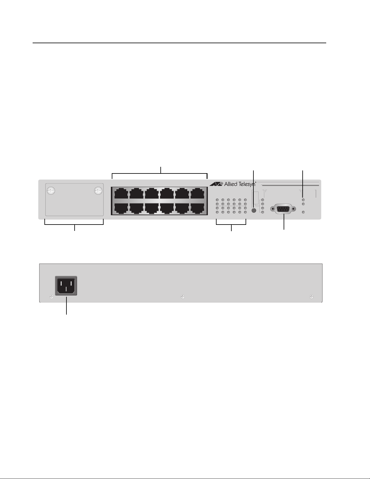
AT-8012M The AT-8012M is a 12-port 10/100Base-TX managed Fast Ethernet switch
with one module expansion slot. The expansion slot is compatible with
100Base and 1000Base fiber optic and twisted pair port expansion
modules and the AT-STACKM stacking module. The 10/100Base-TX
twisted pair ports feature RJ-45 connectors with a maximum operating
distance of 100 meters (328 feet). Refer to ”10/100Base-TX Twisted Pair
Ports” on page 24 and ”Module Expansion Slots” on page 29 for
additional information.
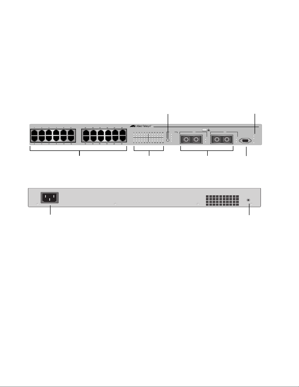
Figure 1 illustrates the front and back panels of the AT-8012M switch.
AT-8000 Series Fast Ethernet Switches Installation Guide
Module Expansion Slot
AC Power
Connector
10/100Base-TX Ports
1357911
24681012
LED Mode
Select Button
AT-8012M
10Base-T /100Base-TX Fast Ethernet Switch
1357911
LINK
MODE
LINK
MODE
24681012
Status LEDs
MODE
RS-232 TERMINAL PORT
COL
100
FULL
ACT
Terminal Port
LED Mode
Select Button
RS-232
STATUS
FAULT
MASTER
PWR
Figure 1. AT-8012M Front and Back Panels
13
Page 14
Overview
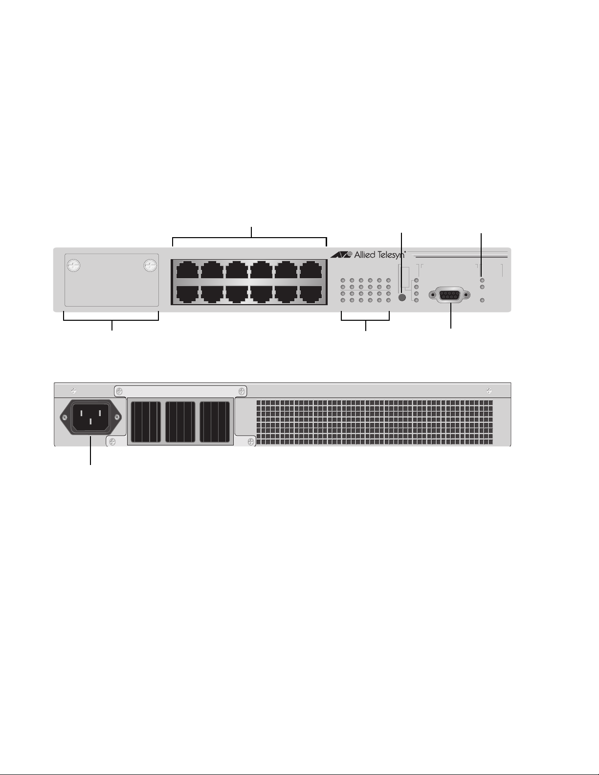
AT-8012M-QS The AT-8012M-QS is a 12-port 10/100Base-TX managed Fast Ethernet
switch with one module expansion slot and operates without a fan. The
expansion slot is compatible with 100Base and 1000Base fiber optic and
twisted pair port expansion modules and the AT-STACKM stacking
module. The 10/100Base-TX twisted pair ports feature RJ-45 connectors
with a maximum operating distance of 100 meters (328 feet). Refer to
”10/100Base-TX Twisted Pair Ports” on page 24 and ”Module Expansion
Slots” on page 29 for additional information.
Figure 1 illustrates the front and back panels of the AT-8012M-QS switch.
Module Expansion Slot
AC Power
Connector
10/100Base-TX Ports
1357911
24681012
LED Mode
Select Button
AT-8012M-QS
10Base-T /100Base-TX Fast Ethernet Switch
1357911
LINK
MODE
LINK
MODE
24681012
Status LEDs
MODE
RS-232 TERMINAL PORT
COL
100
FULL
ACT
Terminal Port
LED Mode
Select Button
RS-232
STATUS
FAULT
MASTER
PWR
14
Figure 2. AT-8012M-QS Front and Back Panels
Page 15
AT-8000 Series Fast Ethernet Switches Installation Guide
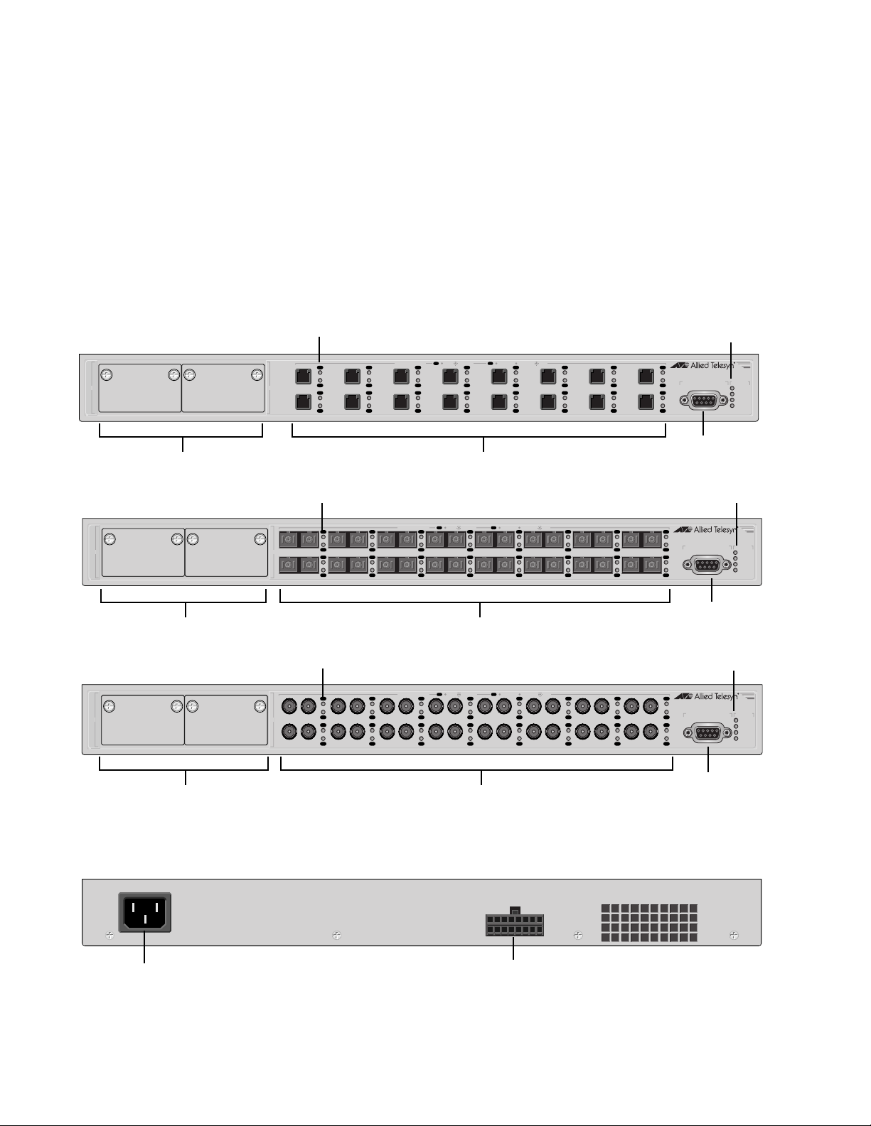
AT-8016F/xx The AT-8016F/MT, AT-8016F/SC, and AT-8016F/ST are 16-port, 100Base-
FX managed Fast Ethernet switches with two module expansion slots.
The expansion slots are compatible 100Base and 1000Base fiber optic
and twisted pair port expansion modules and the AT-STACKM stacking
module. The 100Base-FX fiber optic ports feature MT-RJ, SC, or ST
connectors and a maximum operating distance of 2 kilometers (1.24
miles) or 412 meters (1,360 feet), depending on the duplex mode. Refer
to ”100Base-FX Fiber Optic Ports” on page 23 and ”Module Expansion
Slots” on page 29 for additional information.
Figure 3 and Figure 4 illustrate the front and back panels of the
AT-8016F/xx switches.
AT-8016F/MT
Module Expansion Slots
AT-8016F/SC
17
Expansion Module Slots
AT-8016F/ST
17
Port LEDs
1817
Port LEDs
18
Port LEDs
TX RX
18
TX RX
1TX RX
9TX RX
1
9
System LEDs
L/A
PORT ACTIVITY
L/A
D/C
1
L/A
D/C
9
L/A
D/C
2
10
3
L/A
D/C
11
LINK / ACTIVITY
L/A
D/C
L/A
D/C
100Base-FX Ports
D/C
HALF DUP/
COL
FULL DUP
L/A
D/C
4
L/A
D/C
12
L/A
D/C
5
L/A
D/C
13
L/A
D/C
6
L/A
D/C
14
L/A
D/C
7
L/A
D/C
15
8
16
L/A
AT-8016F/MT
100Base-FX Fast Ethernet Switch
RS-232 TERMINAL PORT
D/C
L/A
D/C
STATUS
FAULT
MASTER
RPS
PWR
RS-232
Terminal Port
System LEDs
L/A
PORT ACTIVITY
2TX RX
10TX RX
L/A
D/C
3TX RX
L/A
D/C
11TX RX
L/A
D/C
L/A
D/C
LINK / ACTIVITY
L/A
D/C
4TX RX
L/A
D/C
12TX RX
D/C
HALF DUP/
COL
FULL DUP
5TX RX
13TX RX
L/A
D/C
L/A
D/C
L/A
D/C
L/A
D/C
6TX RX
14TX RX
L/A
D/C
L/A
D/C
7TX RX
15TX RX
L/A
D/C
L/A
D/C
8TX RX
16TX RX
L/A
AT-8016F/SC
100Base-FX Fast Ethernet Switch
RS-232 TERMINAL PORT
D/C
L/A
D/C
STATUS
FAULT
MASTER
RPS
PWR
RS-232
100Base-FX Ports
Terminal Port
System LEDs
L/A
PORT ACTIVITY
2
TX RX
10
TX RX
L/A
D/C
3
TX RX
L/A
D/C
11
TX RX
L/A
D/C
L/A
D/C
LINK / ACTIVITY
L/A
D/C
4
TX RX
L/A
D/C
12
TX RX
D/C
HALF DUP/
COL
FULL DUP
5
TX RX
13
TX RX
L/A
D/C
L/A
D/C
L/A
D/C
L/A
D/C
6
TX RX
14
TX RX
L/A
D/C
L/A
D/C
7
TX RX
15
TX RX
L/A
D/C
L/A
D/C
8
TX RX
16
TX RX
L/A
AT-8016F/ST
100Base-FX Fast Ethernet Switch
RS-232 TERMINAL PORT
D/C
L/A
D/C
STATUS
FAULT
MASTER
RPS
PWR
Expansion Module Slots
AC Power
Connector
100Base-FX Ports
Figure 3. AT-8016F/xx Front Panels
RPS
Connector
Figure 4. AT-8016F/xx BackPanel
RS-232
Terminal Port
15
Page 16
Overview
AT-8024 The AT-8024 is a 24-port 10/100Base-TX managed Fast Ethernet switch.
The 10/100Base-TX twisted pair ports feature RJ-45 connectors and a
maximum operating distance of 100 meters (328 feet). Refer to ”10/
100Base-TX Twisted Pair Ports” on page 24 for additional information on
the ports.
Figure 5 illustrates the front and back panels of the AT-8024 switch.
AC Power
Connector
10/100Base-TX Ports
LED Mode
Select Button
AT-8024
10Base-T/100Base-TX Fast Ethernet Switch
Link
Mode
Link
Mode
MODE
COL
100
FULL
ACT
Port LEDs
Figure 5. AT-8024 Front and Back Panels
System
LEDs
RS-232 TERMINAL PORT
RS-232
Terminal Port
RESET
Reset
Button
FAULT
MASTER
PWR
16
Page 17
AT-8000 Series Fast Ethernet Switches Installation Guide
AT-8024GB The AT-8024GB is a 24-port 10/100Base-TX managed Fast Ethernet
switch with two GBIC expansion slots. The GBIC expansion slots are
compatible with fiber optic GBIC modules. The 10/100Base-TX twisted
pair ports feature RJ-45 connectors with a maximum operating distance
of 100 meters (328 feet). Refer to ”10/100Base-TX Twisted Pair Ports” on
page 24 and ”Gigabit Interface Converter (GBIC) Expansion Slots” on
page 28 for additional information.
Figure 6 illustrates the front and back panels of the AT-8024GB switch.
AC Power
Connector
10/100Base-TX Ports
LED Mode Select Button
AT-8024GB
10Base-T/100Base-TX Fast Ethernet Switch
Link
Mode
Link
Mode
Port LEDs
MODE
COL
100
FULL
ACT
CLASS 1
LASER PRODUCT
DO NOT STARE
INTO BEAM
PORT A
LINK
MODE
GBIC Expansion
PORT B
Slots
Figure 6. AT-8024GB Front and Back Panels
System LEDs
RS-232 TERMINAL PORT
LINK
MODE
RS-232
Terminal Port
RESET
Reset
Button
FAULT
MASTER
PWR
17
Page 18
Overview
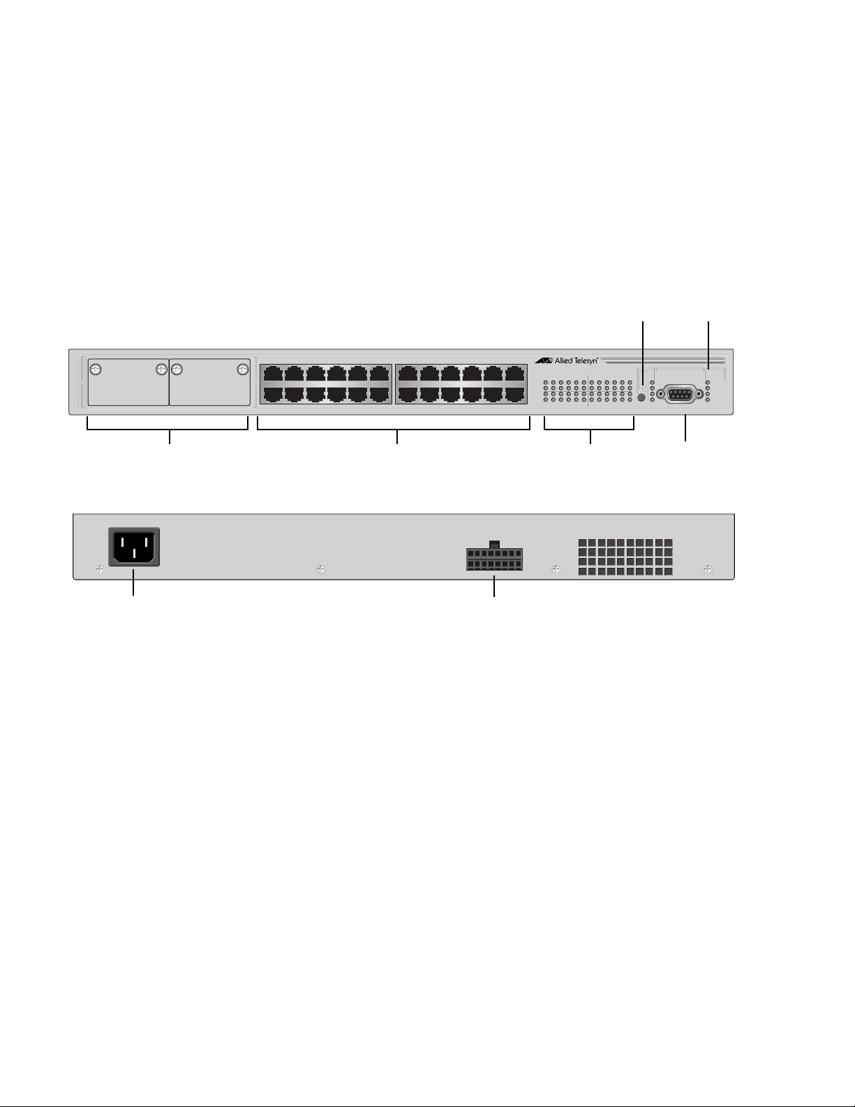
AT-8024M The AT-8024M is a 24-port 10/100Base-TX managed Fast Ethernet switch
with two module expansion slots. The expansion slots are compatible
with 100Base and 1000Base fiber optic and twisted pair port expansion
modules and the AT-STACKM stacking module. The 10/100Base-TX
twisted pair ports feature RJ-45 connectors with a maximum operating
distance of 100 meters (328 feet). Refer to ”10/100Base-TX Twisted Pair
Ports” on page 24 and ”Module Expansion Slots” on page 29 for
additional information.
Figure 7 illustrates the front and back panels of the AT-8024M switch.
25
Module Expansion Slots
AC Power
Connector
1357911
26
2 4 6 8 10 12
10/100Base-TX Ports
Figure 7. AT-8024M Front and Back Panels
13 15 17 19 21 23
14 16 18 20 22 24
RPS
Connector
LED Mode
Select Button
AT-8024M
10Base-T/100Base-TX Fast Ethernet Switch
1 3 5 7 9 11 13 15 17 19 21 23
LINK
MODE
LINK
MODE
2 4 6 8 1012141618202224
Port LEDs
System
LEDs
MODE
COL
100
FULL
ACT
RS-232 TERMINAL PORT
STATU S
RS-232
Terminal Port
FAULT
MASTER
RPS
PWR
18
Page 19
AT-8000 Series Fast Ethernet Switches Installation Guide
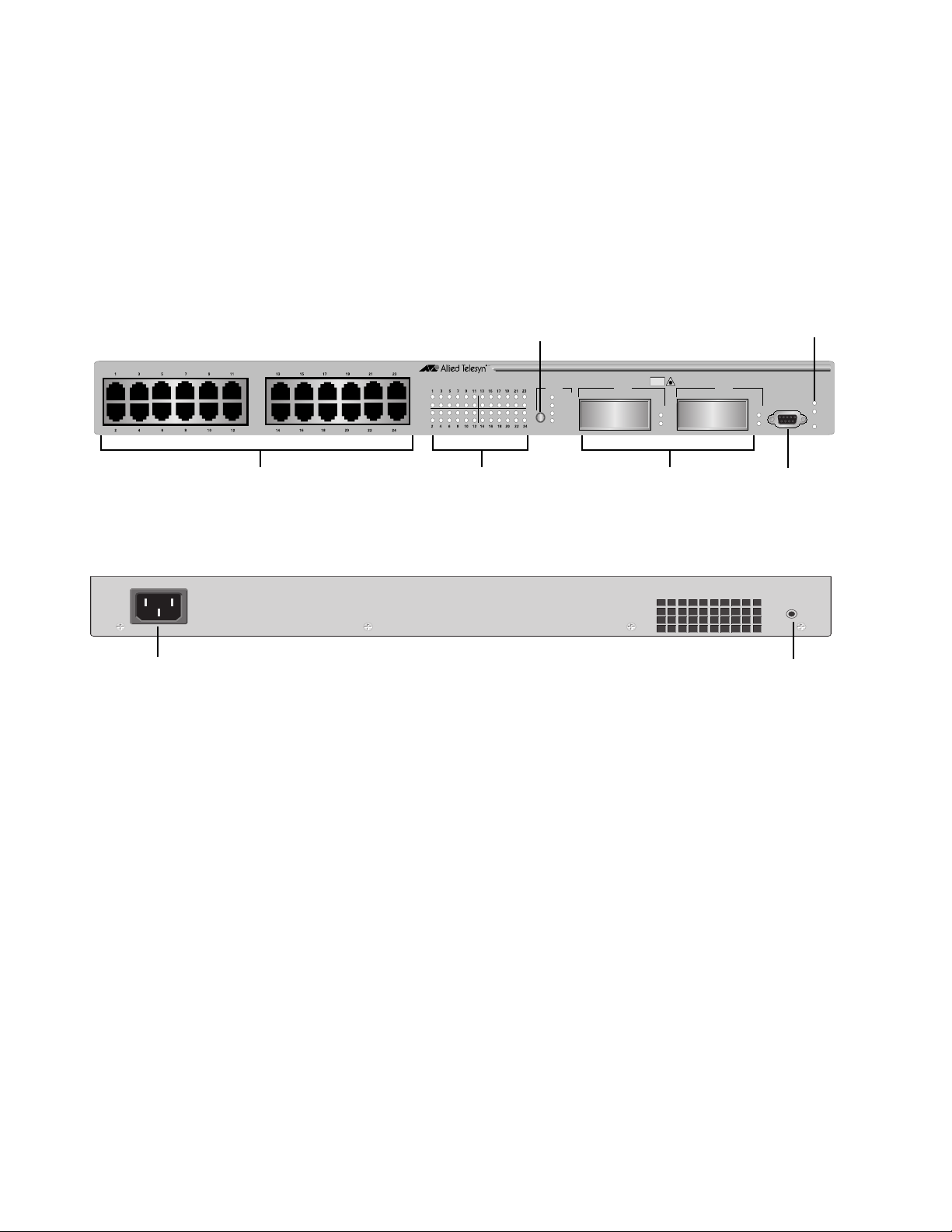
AT-8026FC The AT-8026FC is a 24-port 10/100Base-TX ports and two-port 100Base-
FX managed Fast Ethernet switch. The 100Base-FX fiber optic ports
feature SC connectors and a maximum operating distance of up to 2
kilometers (1.24 miles) or 412 meters (1,360 feet), depending on the
duplex mode. The 10/100Base-TX twisted pair ports feature RJ-45
connectors and a maximum operating distance of 100 meters (328 feet).
Refer to ”100Base-FX Fiber Optic Ports” on page 23 and ”10/100Base-TX
Twisted Pair Ports” on page 24 for additional information.
Figure 8 illustrates the front and back panel of the AT-8026FC switch.
AC Power
Connector
10/100Base-TX Ports
LED Mode Select Button
AT-8026FC
10Base-T/100Base-TX Fast Ethernet Switch
Link
Mode
Link
Mode
Port LEDs
MODE
COL
100
FULL
ACT
TX TXRX RX
CLASS 1
LASER PRODUCT
DO NOT STARE
INTO BEAM
25
LINK
MODE
26
100Base-FX RS-232
Fiber Optic Ports
Figure 8. AT-8026FC Front and Back Panels
System LEDs
RS-232 TERMINAL PORT
LINK
MODE
FAULT
MASTER
PWR
Terminal Port
RESET
Reset
Button
19
Page 20
Overview
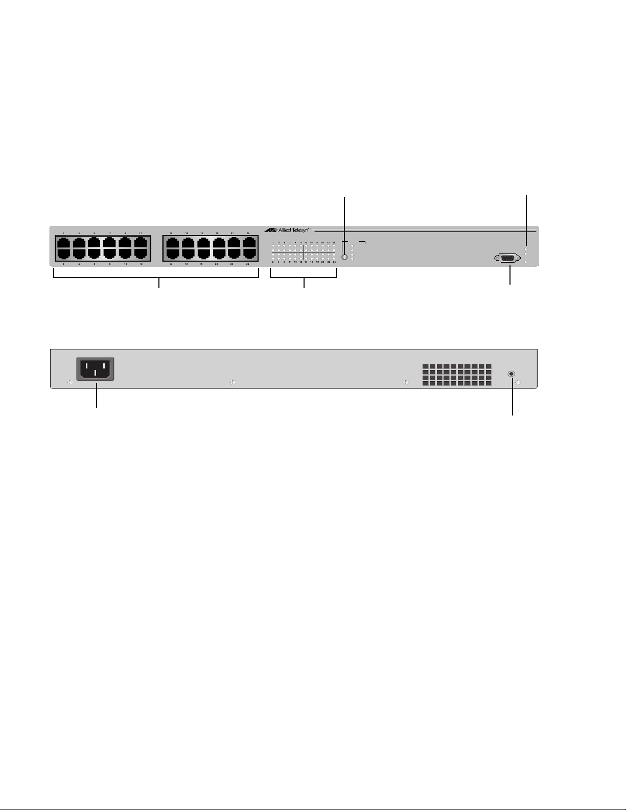
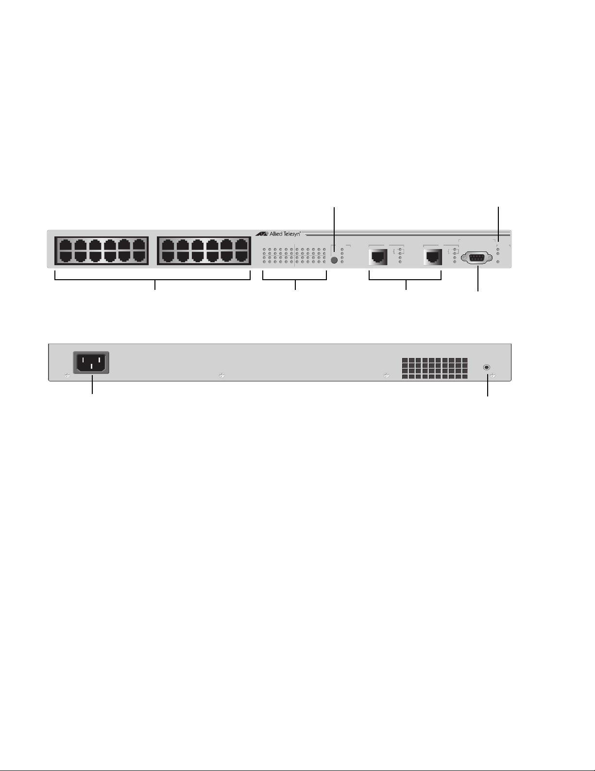
AT-8026T The AT-8026T switch has 24 10/100Base-TX ports and two twisted pair
10/100/1000Base-T ports. The Gigabit ports feature RJ-45 connectors
with a maximum operating distance of 100 meters (328 feet). The 10/
100Base-TX twisted pair ports features RJ-45 connectors with a
maximum operating distance of 100 meters (328 feet). Refer to ”10/
100Base-TX Twisted Pair Ports” on page 24 and ”10/100/1000Base-T
Twisted Pair Ports” on page 26 for further information.
Figure 9 illustrates the front and back panels of the AT-8026T switch.
1357911
24681012
10/100Base-TX Ports
AC Power
Connector
13 15 17 19 21 23
14 16 18 20 22 24
LED Mode Select Button
AT-8 0 2 6 T
10Base-T/100Base-TX Fast Ethernet Switch with 10/100/1000Base-T Uplinks
1 3 5 7 9 11131517192123
LINK
MODE
LINK
MODE
2 4 6 8 10 12 14 16 18 20 22 24
Port LEDs
COL
100
FULL
ACT
10
1000
LINK
100
FULL
ACT
10/100/1000BASE-T 10 /100/1000BASE-T
10/100/1000Base-T
Ports
Figure 9. AT-8026T Front and Back Panels
System LEDs
RS-232 TERMINAL PORT
2625MODE
10
1000
LINK
100
FULL
ACT
RS-232
Terminal Port
Button
RESET
Reset
STATUS
FAULT
MASTER
PWR
20
Page 21
AT-8000 Series Fast Ethernet Switches Installation Guide
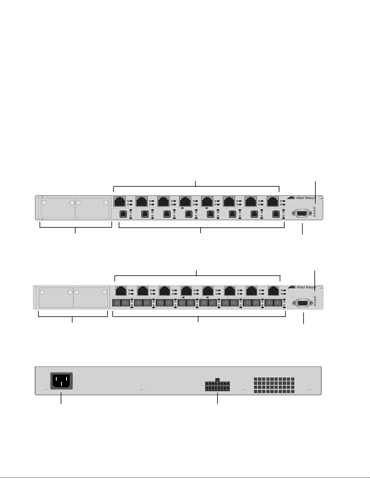
AT-8088/xx The AT-8088/MT and AT-8088/SC switches have eight 10/100Base-TX
ports and eight 100Base-FX ports with two module expansion slots. The
expansion slots are compatible with 100Base and 1000Base fiber optic
and twisted pair port expansion modules and the AT-STACKM stacking
module. The 100Base-FX fiber optic ports feature MT-RJ or SC
connectors with a maximum operating distance of 2 kilometers (1.24
miles), depending on the duplex mode. The 10/100Base-TX twisted pair
ports feature RJ-45 connectors with a maximum operating distance of
100 meters (328 feet). Refer to ”100Base-FX Fiber Optic Ports” on page
23, ”10/100Base-TX Twisted Pair Ports” on page 24, and ”Gigabit
Interface Converter (GBIC) Expansion Slots” on page 28 for more
information.
Figure 10 and Figure 11 illustrate the front and back panels of the
AT-8088/xx switches.
AT-8088/MT
Module Expansion Slots
AT-8088/SC
Module Expansion Slots
System
10/100Base-TX Ports
1234567
L/A
1817
D/C
L/A
D/C
L/A
D/C
L/A
D/C
PORT ACTIVITY
L/A
D/C
L/A
D/C
L/A
LINK / ACTIVITY
L/A
D/C
L/A
D/C
L/A
D/C
D/C
HALF DUP/
FULL DUP
L/A
D/C
COL
L/A
D/C
L/A
D/C
100Base-FX Ports
L/A
D/C
L/A
D/C
8
L/A
D/C
L/A
D/C
161514131211109
AT- 8088/MT
8 Port 10Base-T/100Base-TX
8 Port 100Base-FX Fast Ethernet Switch
RS-232 TERMINAL PORT
RS-232
LEDs
STATUS
FAULT
MASTER
RPS
PWR
Terminal Port
System
10/100Base-TX Ports
12345678
L/A
1817
D/C
L/A
D/C
L/A
D/C
L/A
D/C
PORT ACTIVITY
L/A
D/C
L/A
D/C
L/A
LINK / ACTIVITY
L/A
D/C
L/A
D/C
L/A
D/C
D/C
HALF DUP/
FULL DUP
L/A
D/C
COL
L/A
D/C
L/A
D/C
L/A
D/C
L/A
D/C
16TX RX15TX RX14TX RX13TX RX12TX RX11TX RX10TX RX9TX RX
L/A
AT- 8088/SC
8 Port 10Base-T/100Base-TX
8 Port 100Base-FX Fast Ethernet Switch
D/C
L/A
D/C
100Base-FX Ports
RS-232 TERMINAL PORT
RS-232
LEDs
STATUS
FAULT
MASTER
RPS
PWR
Terminal Port
AC Power
Connector
Figure 10. AT-8088/xx Front Panels
RPS
Connector
Figure 11. AT-8088/xx (MT and SC) Back Panel
21
Page 22

Overview
Hardware Features
The following sections describe these hardware features of the AT-8000
Series Fast Ethernet Switches:
”100Base-FX Fiber Optic Ports” on page 23
”10/100Base-TX Twisted Pair Ports” on page 24
”10/100/1000Base-T Twisted Pair Ports” on page 26
”Gigabit Interface Converter (GBIC) Expansion Slots” on page 28
”Module Expansion Slots” on page 29
”Twisted Pair Port LEDs and the LED Mode Select Button” on page
30
”Fiber Optic Port LEDs” on page 32
”System LEDs” on page 34
”RS-232 Terminal Port” on page 35
”Reset Button” on page 36
”RPS Connector” on page 37
”AC Power Connector” on page 38
”DC Power Connector” on page 39
22
Page 23

100Base-FX Fiber Optic Ports
The AT-8016F/MT, AT-8016F/SC, and AT-8016F/ST switches feature 16
fiber optic ports. The AT-8026FC switch have two fiber optic ports. The
AT-8088/MT and AT-8088/SC switches have eight fiber optic ports. The
operating characteristics of the fiber optic ports on all the switches are
the same.
AT-8000 Series Fast Ethernet Switches Installation Guide
Type of
Connector
The fiber optic ports on the AT-8016F/SC, AT-8026FC, and AT-8088/SC
switches feature SC connectors.
The fiber optic ports on the AT-8016F/ST switch features ST connectors.
The fiber optic ports on the AT-8016F/MT and AT-8088/MT switches
feature MT-RJ connectors.
Speed The fiber optic ports have a fixed operating speed of 100 megabits per
second (Mbps). The speed cannot be changed.
Duplex Mode The fiber optic ports can operate in either half- or full-duplex mode. You
can set the duplex mode manually or allow the switch to set it
automatically through Auto-Negotiation.
Maximum
Distance
Each fiber optic port has a maximum operating distance of 2 kilometers
(1.25 miles) when operating in full-duplex mode and 412 meters (1,360
feet) when operating in half-duplex mode.
Type of Cable The fiber optic ports can use either 50/125 or 62.5/125 micron
multimode fiber optic cable.
Note
Do not use single-mode fiber optic cable with these ports.
23
Page 24

Overview
10/100Base-TX Twisted Pair Ports
The twisted pair ports featured on the AT-8000 Series Switch are
described below.
Type of
Connector
All twisted pair ports feature 8-pin RJ-45 connectors. For the port
pinouts, refer to ”RJ-45 Twisted Pair Port Pinouts” on page 85.
Speed The twisted pair ports are 10/100Base-TX compliant and are capable of
both 10 megabits per second (Mbps) and 100 Mbps speeds. You can set
the port speed manually or, since the ports are IEEE 802.3u AutoNegotiation compliant, you can let the switch set each port’s speed
automatically. With Auto-Negotiation, the switch automatically matches
the highest possible common speed between each switch port and each
end-node. For example, if an end-node is capable of only 10 Mbps, the
switch sets the port connected to the end-node to 10 Mbps.
Note
Auto-Negotiation is activated as the default on all twisted pair ports
on the switch. To deactivate Auto-Negotiation and set the speeds
manually, refer to the AT-S39 Management Software User’s
Guide.
Duplex Mode Each twisted pair port on the switch can operate in either half- or full-
duplex mode. The twisted pair ports are IEEE 802.3u-compliant and will
Auto-Negotiate the duplex mode setting.
Maximum
Distance
If desired, Auto-Negotiation on one or all of the switch ports can be
disabled so that you can set the duplex mode manually through the
switch’s management software.
Note
In order for a switch port to successfully Auto-Negotiate its duplex
mode with an end-node, the end-node should also be using AutoNegotiation. Otherwise, a duplex mode mismatch can occur. A
switch port, using Auto-Negotiation, will default to half-duplex if it
detects that the end-node is not using Auto-Negotiation. This will
result in a mismatch if the end-node is operating at a fixed duplex
mode of full-duplex. Consequently, when connecting an end-node
with a fixed duplex mode of full-duplex to a switch port, you should
use the AT-S39 management software to disable Auto-Negotiation
on the port and set the port speed and duplex mode manually.
Each twisted pair port has a maximum operating distance of 100 meters
(328 feet).
24
Page 25

AT-8000 Series Fast Ethernet Switches Installation Guide
Type of Cabling For 10 Mbps operation, Category 3 or better 100 ohm shielded or
unshielded twisted pair cabling is required. For 100 Mbps operation,
Category 5 or Enhanced Category 5 (5E) 100 ohm shielded or unshielded
twisted pair cabling is required.
Auto MDI/
MDI-X
The twisted pair ports are auto-MDI/MDI-X. They automatically
configure themselves as either MDI or MDI-X. This feature allows you to
use a straight-through twisted pair cable to connect any type of network
device to a switch port.
Note
Disabling Auto-Negotiation on a port also disables Auto MDI/MDI-X
on the port. You must set the MDI/MDI-X manually through the
management software, refer to the AT-S39 Management
Software User’s Guide.
Port Pinouts Refer to Table 9 on page 85 and Table 10 on page 85 for the port
pinouts.
25
Page 26

Overview
10/100/1000Base-T Twisted Pair Ports
The two twisted pair 10/100/1000Base-T ports featured on the AT-8026T
are described below.
Type of
Connector
The ports have 8-pin RJ-45 connectors. The ports use four pins when
operating at 10 or 100 Mbps and all eight pins when operating at
1000 Mbps.
Speed The ports can operate at 10, 100, or 1000 Mbps. The speed is set
automatically through Auto-Negotiation or you can set the speed
manually through the management software.
Duplex Mode The ports can operate in either half- or full-duplex mode. The ports are
IEEE 802.3u compliant and will Auto-Negotiate the duplex mode. If
needed, Auto-Negotiation can be disabled so that you can set the
duplex mode manually through the management software.
Note
In order for a switch port to successfully Auto-Negotiate its duplex
mode with an end-node, the end-node should also be using AutoNegotiation. Otherwise, a duplex mode mismatch can occur. A
switch port, using Auto-Negotiation, will default to half-duplex if it
detects that the end-node is not using Auto-Negotiation. This will
result in a mismatch if the end-node is operating at a fixed duplex
mode of full-duplex. Consequently, when connecting an end-node
with a fixed duplex mode of full-duplex to a switch port, you should
use the AT-S39 management software to disable Auto-Negotiation
on the port and set the port speed and duplex mode manually.
Maximum
The ports have a maximum operating distance of 100 meters (328 feet).
Distance
Type of Cable For 10 Mbps, the port requires Category 3 or better 100 ohm shielded or
unshielded twisted pair cabling. For 100 or 1000 Mbps operation, the
ports require Category 5 or Enhanced Category 5 (5E) 100 ohm shielded
or unshielded twisted pair cabling.
26
Page 27

AT-8000 Series Fast Ethernet Switches Installation Guide
Auto MDI/
MDI-X
The ports are auto-MDI/MDI-X. They automatically configure themselves
as either MDI or MDI-X. This feature allows you to use a straight-through
twisted pair cable to connect any type of network device to a switch
port.
Note
Disabling Auto-Negotiation on a port also disables Auto MDI/MDI-X
on the port. You must set the MDI/MDI-X manually through the
management software, refer to the AT-S39 Management
Software User’s Guide.
Port Pinouts For the pinouts of these ports when operating at 10 or 100 Mbps in the
MDI configuration, refer to Table 9 on page 85. For the pinouts of the
ports when operating at 10 or 100 Mbps in the MDI-X configuration,
refer to Table 10 on page 85. For port pinouts when the ports are
operating at 1000 Mbps, refer to Table 11 on page 86.
27
Page 28
Overview
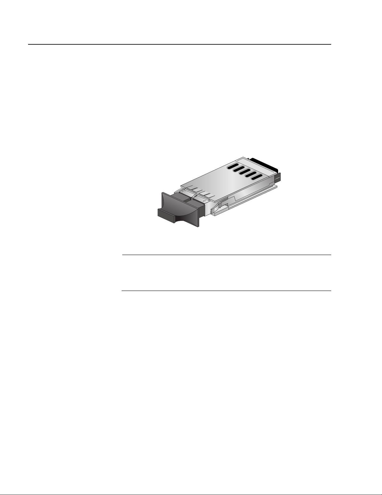
Gigabit Interface Converter (GBIC) Expansion Slots
The AT-8024GB Fast Ethernet Switch has two expansion slots on the
front panel, labelled Port A and Port B, which correspond to Ports 25 and
26, respectfully. Each slot can accommodate one optional fiber optic
Gigabit Interface Converter (GBIC) Ethernet module.
An GBIC module is a fast and easy way for you to add an 1000 Mbps fiber
optic port to your Fast Ethernet switch. GBIC modules can be used to
extend the distance of your network, build a high-speed backbone
network between switches, or connect additional end-nodes to the
network, such as high-speed servers.
Figure 12 shows an example of a fiber optic GBIC module.
Figure 12. GBIC Module
Note
For a list of the Allied Telesyn GBIC modules supported by the
AT-8024GB Fast Ethernet Switch, contact your Allied Telesyn sales
representative.
28
Page 29

Module Expansion Slots
The AT-8016/xx, AT-8024M, and AT-8088/xx switches have two
expansion slots. The AT-8012M and AT-8012M-QS have one expansion
slot. Each slot can accommodate an expansion module. You can use the
slots to add 100Base and 1000Base fiber optic and twisted pair ports to
the switch.
Note
For a list of the Allied Telesyn expansion modules supported by the
switches, contact your Allied Telesyn sales representative or refer to
our website at: www.alliedtelesyn.com.
AT-8000 Series Fast Ethernet Switches Installation Guide
29
Page 30

Overview
Twisted Pair Port LEDs and the LED Mode Select Button
The twisted pair port LEDs and the LED Mode Select button for the
AT-8000 Series Switches are describe below.
The port LEDs on the front panel display port status information. Each
port has two LEDs. The Link LED indicates whether there is a valid link
between a port and the end-node connected to it.
Each port also has a Mode LED. This LED displays a variety of status
information, including port speed and duplex mode. You use the Mode
Select button on the front panel to toggle the Mode LEDs to display
different status information. The LEDs next to the Mode Select button
indicate the status being displayed by the port Mode LEDs. For example,
if the Mode 100 LED is green, then the port Mode LEDs are displaying
port speed.
Note
Toggling the Mode Selection button does not affect the normal
operations of the switch.
Table 2 describes the twisted pair port LEDs of the AT-8000 Series
Switches, except for the AT-8088/xx switch, which does not have a LED
Mode Select button.
Table 2. AT-8000 Series Twisted Pair Port LEDs
LED State Description
LINK OFF Indicates that there is no link between the
port and the end-node.
Green Indicates a valid link has been established
between the port and the end-node.
Mode - COL OFF Indicates that no data collisions are
occurring on the port.
Flashing
Green
Indicates that data collisions are occurring
on the port.
Mode - 100 OFF Indicates that the port is operating at 10
Mbps.
30
Green Indicates that the port is operating at 100
Mbps
Page 31

AT-8000 Series Fast Ethernet Switches Installation Guide
Table 2. AT-8000 Series Twisted Pair Port LEDs
LED State Description
Mode - FULL OFF Indicates that the port is operating in half-
duplex mode.
Green Indicates that the port is operating in full-
duplex mode.
Mode - ACT OFF Indicates that there is no activity on the
port.
Flashing
Green
Indicates that the port is transmitting and/
or receiving data packets.
The twisted pair ports on the AT-8088/xx switch has two port LEDs,
labeled L/A and D/C. These port LEDs are defined in Table 3 below.
Table 3. AT-8088/xx Twisted Pair Port LEDs
LED State Description
L/A OFF Indicates that there is no link between the
port and the end-node.
Green Indicates a valid link has been established
between the port and the end-node.
Flashing
Green
Indicates that the port is transmitting and/
or receiving data packets.
D/C Green Indicates that the port is operating in full-
duplex mode.
Amber Indicates that the port is operating in half-
duplex mode.
Flashing
Amber
Indicates that data collisions are occurring
on the port.
31
Page 32

Overview
Fiber Optic Port LEDs
The fiber optic ports for the AT-8016F/xx, AT-8024GB (GBIC slots),
AT-8026FC, and AT-8088 switches are described below.
The fiber optic ports on the AT-8016F/xx and AT-8088/xx switches have
two LEDs, labeled L/A and D/C. The LEDs are defined in Table 4.
LED State Description
L/A OFF Indicates that there is no link between the port
Table 4. AT-8016/xx and AT-8088/xx Fiber Optic Port LEDs
and the end-node.
Green Indicates a valid link has been established
between the port and the end-node.
Flashing
Green
Indicates that the port is transmitting and/or
receiving data packets.
D/C Green Indicates that the port is operating in full-
duplex mode.
Amber Indicates that the port is operating in half-
duplex mode.
Flashing
Amber
Indicates that data collisions are occurring on
the port.
Note
The AT-8016F/xx and AT-8088/xx switches do not have a LED Mode
Select button.
32
Page 33

AT-8000 Series Fast Ethernet Switches Installation Guide
Next to each GBIC slot on the AT-8024GB Switch and fiber optic port on
the AT-8026FC Switch are two LEDs. The LEDs display the operating
status of the fiber optic port. Use the Mode Select button on the switch
to toggle the status information displayed by the MODE LED. The LEDs
are defined in Table 5.
Table 5. AT-8024GB and AT-8026FC Fiber Optic Port LEDs
LED State Description
LINK OFF Indicates that there is no link between the
port and the end-node.
Solid
Green
Indicates a valid link has been established
between the port and the end-node.
Mode - COL OFF Indicates that no data collisions are
occurring on the port.
Flashing
Green
Mode - 100 Solid
Green
Indicates that data collisions are occurring
on the port.
Indicates that the port is operating at 1000
Mbps (AT-8024GB switch) or 100 Mbps
(AT-8026FC switch).
Mode - FULL OFF Indicates that the port is operating in
half-duplex mode.
Solid
Green
Indicates that the port is operating in
full-duplex mode.
Mode - ACT OFF Indicates that there is no activity on the
port.
Flashing
Green
Indicates that the port is transmitting and/
or receiving data packets.
33
Page 34

Overview
System LEDs
The system LEDs on the front panel display general status information.
They are defined in Table 6.
Table 6. System LEDs
LED State Description
Fault OFF Indicates normal operation.
Red Indicates that the switch or management
software has malfunctioned. (Refer to
”Troubleshooting” on page 75 for instructions
on how to troubleshoot the problem.)
Flashing
Red
Indicates that the switch is loading its
operating software, running diagnostic tests,
writing messages to FLASH, or downloading
files using XMODEM.
Master Amber Indicates that the switch is functioning as the
master switch of an enhanced stack.
OFF Indicates that the switch is not a master switch
of an enhanced stack or is not a member of a
stack.
PWR Green Indicates that the switch is receiving power.
AT-8016F/xx, AT- 8024M, and AT-8088/xx Switches Only
RPS Green Indicates that an optional redundant power
supply is connected to the switch.
OFF Indicates that there is no optional redundant
power supply connected to the switch.
34
Page 35

RS-232 Terminal Port
The RS-232 terminal port on the AT-8000 Series Switch is described
below.
The RS-232 Terminal Port is used to establish a local (out-of-band)
management session with the switch and to configure the switch’s
operating parameters. To establish a local management session, you
connect either a terminal or a personal computer with a terminal
emulation program to the port.
Note
You are not required to manage the AT-8000 Series Fast Ethernet
Switch. The default switch settings may be sufficient for your
network, in which case you can use the unit as an unmanaged
switch. For the switch’s default settings, refer to AT-S39
Management Software User’s Guide.
The RS-232 Terminal Port has a DB-9 female connector and uses a
straight-through RS-232 cable (not provided). The default settings for
the RS-232 Terminal Port are:
AT-8000 Series Fast Ethernet Switches Installation Guide
Baud rate: Auto-detect
(range 1200 to 115200 bps; default 9600 bps)
Data bits: 8
Parity: None
Stop bits: 1
Flow control: None
Note
These default settings are for a DEC VT100 or ANSI terminal, or an
equivalent terminal emulation program.
35
Page 36

Overview
Reset Button
The Reset button on the AT-8024, AT-8024GB, AT-8026FC, and AT-8026T
switches is described below.
Note
The AT-8012M, AT-8012M-QS, AT-8016F/xx, and AT-8024M
switches do not have a Reset button. You can reset these systems
through the AT-S39 management software or by power cycling the
unit by disconnecting and reconnecting the power cord.
The switches listed above have a Reset button on the back panel. You
might need to reset the switch under the following conditions:
To resolve a switch problem.
To reset the switch statistics stored by the management software.
The button is recessed in the switch’s chassis. You will need to use a pen
or the end of a paper clip to press the button.
You can also reset the switch using the management interface, as
explained in the AT-S39 Management Software User’s Guide.
Note
Resetting the switch causes the device to momentarily stop
forwarding data packets while it loads its operating software. This
will interrupt normal network operations. The switch will resume
forwarding packets once it has completed reloading its software, a
task that requires only a few seconds to complete.
36
Page 37

RPS Connector
AT-8000 Series Fast Ethernet Switches Installation Guide
The RPS connector on the AT-8024M, AT-8016F/xx, and AT-8088/xx
switches is described below.
The RPS connector on the back panel of the switch connects to the
optional AT-RPS3004 redundant power supply unit, shown in Figure 13.
The unit can provide power to the switch in the event the switch’s
internal power supply should fail.
The AT-RPS3004 redundant external power supply comes with one preinstalled AT-PWR3004 Power Module and has three empty slots for
additional power modules. Each power module can support one switch,
making the AT-RPS3004 unit capable of supporting up to four switches
simultaneously.
Figure 13. AT-RPS3004 Redundant Power Supply Unit
37
Page 38

Overview
AC Power Connector
The AC power connector for the AT-8000 Series Switch is described
below.
The switch has a single AC power supply socket on the back panel,
which has autoswitch AC inputs. To power ON or OFF the switch, you
need to connect or disconnect the power cord.
Refer to ”Technical Specifications” on page 79, for the input voltage
range.
38
Page 39

DC Power Connector
The DC power connector featured on some models of the AT-8000 Series
Switch is described below.
The switch has a DC terminal block on the back panel, which has three
terminals (positive, frame ground, and negative). Refer to ”Wiring a DC
Powered Unit” on page 68, for instructions on how to wire a DC powered
unit.
Refer to ”Technical Specifications” on page 79, for the input voltage
range.
AT-8000 Series Fast Ethernet Switches Installation Guide
39
Page 40

Overview
A Few Basics about Ethernet Switching
An Ethernet switch interconnects network devices, such as workstations,
printers, routers, and other Ethernet switches, so that they can
communicate with each other by sending and receiving Ethernet
frames.
MAC Address
Table
Most of the hardware devices on your network have a unique MAC
address. This address is assigned to a device by the device’s
manufacturer. For example, when you install a Network Interface Card
(NIC) in a computer so that you can connect it to the network, the NIC
already has a MAC address assigned to it by its manufacturer.
An AT-8000 Series Fast Ethernet Switch has a MAC address table of
4 kilobytes. The switch uses the table to store the MAC addresses of the
network end-nodes connected to the ports, along with the port number
on which each address was learned.
A switch learns the MAC addresses of the end-nodes by examining the
source address of each packet received on a port. It adds the address
and port on which the packet was received to the MAC table if the
address had not already been entered in the table. The result is a table
that contains all the MAC addresses of the devices that are connected to
the switch’s ports, and the port number where each address was
learned.
When the switch receives a packet, it also examines the destination
address and, by referring to its MAC address table, determines the port
on which the destination end-node is connected. It then forwards the
packet to the appropriate port and on to the end-node. This increases
network bandwidth by limiting each frame to the appropriate port when
the intended end-node is located, freeing the other switch ports for
receiving and transmitting data.
40
If the switch receives a packet with a destination address that is not in
the MAC address table, it floods the packet to all the ports on the switch.
If the ports have been grouped into virtual LANs, the switch floods the
packet only to those ports which belong to the same VLAN as the port
on which the packet was received. This prevents packets from being
forwarded into inappropriate LAN segments, increasing network
security. When the destination an end-node responds, the switch adds
its MAC address and port number to the table.
Page 41

AT-8000 Series Fast Ethernet Switches Installation Guide
If the switch receives a packet with a destination address that is on the
same port on which the packet was received, it discards the packet
without forwarding it on to any port. Since both the source end-node
and the destination end-node for the packet are located on the same
port on the switch, there is no reason for the switch to forward the
packet.
Duplex Mode Duplex mode refers to how an end-node receives and transmits data. If
an end-node can receive or transmit data, but not both simultaneously,
the end-node is operating in what is referred to as half-duplex mode. If
an end-node can both receive and transmit data simultaneously, the
end-node is said to be operating in full-duplex mode. Naturally, an endnode capable of operating in full-duplex can handle data much faster
than an end-node that can only operate in half-duplex mode.
The twisted pair ports on the AT-8000 Series Switches can operate in
either half- or full-duplex mode. The twisted pair ports are IEEE 802.3ucompliant and will Auto-Negotiate the duplex mode setting for you.
By allowing the switch to configure the duplex mode for each port itself,
you will not need to change the setting for a port on the switch should
you replace an end-node with an end-node that has a different duplex
mode capability. With Auto-Negotiation, the switch will automatically
reset the port to a new duplex mode setting for you.
If desired, Auto-Negotiation on the switch ports can be disabled so that
you can set the duplex mode manually through the switch’s
management software.
Note
In order for a switch port to successfully Auto-Negotiate its duplex
mode with an end-node, the end-node should also be using AutoNegotiation. Otherwise, a duplex mode mismatch can occur. A
switch port, using Auto-Negotiation, will default to half-duplex if it
detects that the end-node is not using Auto-Negotiation. This will
result in a mismatch if the end-node is operating at a fixed duplex
mode of full-duplex. Consequently, when connecting an end-node
with a fixed duplex mode of full-duplex to a switch port, you should
use the AT-S39 management software to disable Auto-Negotiation
on the port and set the port speed and duplex mode manually.
41
Page 42

Overview
Store and
Forward
Backpressure and
Flow Control
These Fast Ethernet Switches use store and forward as the method for
receiving and transmitting frames. When an Ethernet frame is received
on a switch port, the switch does not retransmit the frame out the
destination port until it has received the entire frame and stored the
frame in a port buffer. It then examines the frame to determine if it is a
valid frame. Invalid frames, such as fragments or runts, are discarded by
the switch. This insures that only valid frames are transmitted out the
switch ports and that damaged frames are not propagated on your
network.
In order to maintain the orderly movement of data between the endnodes, an Ethernet switch may periodically need to signal an end-node
to stop sending data.
How a switch signals an end-node to stop transmitting data differs
depending on the speed and duplex mode of the end-node and switch
port. A twisted pair port operating at 100 Mbps port and half-duplex
mode stops an end-node from transmitting data by forcing a collision. A
collision on an Ethernet network occurs when two end-nodes attempt to
transmit data using the same data link at the same time. A collision
causes end-nodes to stop sending data. When the switch needs to stop a
100 Mbps, half-duplex end-node from transmitting data, it forces a
collision on the data link, which stops the end-node. Once the switch is
ready to receive data again, the switch stops forcing collisions. This is
referred to as backpressure.
A port operating at 100 Mbps and full-duplex mode uses PAUSE frames,
as specified in the IEEE 802.3x standard, to stop the transmission of data
from an end-node. Whenever the switch wants an end-node to stop
transmitting data, it issues this frame. The frame instructs the end-node
to cease transmission. The switch continues to issue PAUSE frames until
it is ready again to receive data from the end-node. This is referred to as
flow control.
42
Page 43

Network Topologies
This section illustrates several of the network topologies you can create
with the AT-8000 Series Fast Ethernet Switches.
AT-8000 Series Fast Ethernet Switches Installation Guide
Power
Workgroup
Topology
The topology shown in Figure 14 is commonly referred to as a power
workgroup topology. Each workstation or end-node is connected
directly to a port on an AT-8024 Fast Ethernet Switch. Each end-node has
a dedicated data link to the switch for best performance and reliability.
The devices can operate at either 10 Mbps or 100 Mbps.
AT-8024 Fast
T
R
O
P
L
A
IN
M
R
E
T
2
3
2
S
AT-8024
itch
et Sw
Fast Ethern
-TX
e
s
/100Ba
E
D
O
M
10Base-T
L
O
C
k
n
i
L
0
0
1
L
L
e
U
F
d
o
M
T
C
k
A
n
i
L
e
d
o
M
R
T
L
U
A
F
R
E
T
S
A
M
Ethernet Switch
R
W
P
Legend
10 Mbps
100 Mbps
Figure 14. Power Workgroup Topology
43
Page 44

Overview
Collapsed
Backbone - Hub
Topology
In the topology illustrated in Figure 15, an AT-8024 connects together
10/100 Mbps Ethernet hubs. This type of topology is often referred to as
a collapsed backbone topology. The switch functions as the focal point
of the network by acting as a bridge between the different workgroups.
The switch transfers an Ethernet frame from hub to hub only when the
destination end-node for the frame is on a different hub than the endnode that originated the frame. This reduces the amount of unnecessary
data traffic in each workgroup, freeing up bandwidth and improving
network performance.
AT-8024 Fast
T
R
O
P
L
A
N
I
M
R
E
T
2
3
2
S
R
T
L
U
A
F
R
E
T
S
A
M
Ethernet Switch
R
W
P
1
2
3
54
6
7
8
1
2
3
Ethernet
Hubs
AT-8024
h
ernet Switc
ast Eth
Base-TX F
/100
E
T
-
D
O
Base
M
10
L
O
C
k
n
i
L
0
0
1
L
L
e
U
F
d
o
M
T
C
k
A
n
i
L
e
d
o
M
1
2
3
54
6
7
8
54
6
7
8
44
Legend
10 Mbps
100 Mbps
Figure 15. Collapsed Backbone - Hub Topology
Page 45

AT-8000 Series Fast Ethernet Switches Installation Guide
Mixed Topology You can always combine topologies as well as build a larger network by
connecting different switches together. If the switches are within 100
meters (328 feet) of each other, you can use the twisted pair ports. If the
switches are further apart, then you will need to use fiber optic ports.
Figure 16 illustrates a network of three AT-8026FC Fast Ethernet
Switches. The workstations and servers of the network are connected
either directly to a switch or through an Ethernet hub. The switches
themselves are connected through their fiber optic ports, which have a
maximum operating distance of 2 kilometers (1.24 miles). The figure also
illustrates how you can use the fiber optic ports to connect other remote
devices to the network, such as remote servers and workstations.
AT-8026FC Fast
RS-232 TERMINAL PORT
1
S
S
LA
C
T
C
U
D
O
R
P
R
E
S
A
L
E
R
A
T
S
T
O
N
O
D
M
A
E
B
O
T
N
I
B
T
R
O
B
G
4
2
0
8
T
A
h
c
t
i
w
S
t
e
n
r
e
h
t
E
t
s
a
F
X
T
e
s
a
B
0
0
/1
T
e
s
a
B
0
1
ink
L
de
o
M
ink
L
e
od
M
1
2
3
54
6
7
8
P
A
T
R
O
P
E
OD
M
COL
100
FULL
ACT
FAULT
K
N
MASTER
LI
K
IN
L
DE
MO
Ethernet Switch
PWR
ODE
M
AT-8026FC Fast
Ethernet Switch
Legend
10 Mbps
100 Mbps
100 Mbps
Fiber Optic
AT-8026FC Fast
Ethernet Switch
1
2
3
54
6
7
8
RS-232 TERMINAL PORT
1
S
S
A
L
C
T
C
U
D
O
R
P
R
E
S
A
L
E
R
A
T
S
T
O
N
O
D
M
A
E
B
O
T
N
I
B
T
R
O
B
G
4
2
0
-8
T
A
h
c
t
i
w
S
t
e
n
r
e
h
t
E
t
s
a
F
X
T
e
s
a
B
0
0
1
/
T
e
s
a
B
0
1
ink
L
e
od
M
ink
L
e
d
o
M
P
A
T
R
O
P
E
D
O
M
COL
100
FULL
ACT
FAULT
K
IN
MASTER
L
INK
L
PWR
E
OD
M
E
OD
M
B
G
4
2
0
-8
T
A
h
c
t
i
w
S
t
e
n
r
e
h
t
E
t
s
a
F
X
T
e
s
a
B
0
0
1
/
E
T
-
D
e
s
O
a
B
M
0
1
COL
k
in
L
100
e
FULL
d
o
M
k
ACT
in
L
e
d
o
M
RS-232 TERMINAL PORT
1
S
S
A
L
C
T
C
U
D
O
R
P
R
E
S
A
L
E
R
A
T
S
T
O
N
O
D
M
A
E
B
O
T
N
I
B
T
R
O
P
A
T
R
O
P
FAULT
MASTER
LINK
LINK
PWR
DE
O
M
DE
O
M
Figure 16. Mixed Topology
45
Page 46

Overview
Collapsed
Backbone -
Switch Topology
AT-8024GB Fast Ethernet Switches
If you need to connect together multiple switches and the switches are
physically separated by more than 2 kilometers (1.24 miles), or if you
want to build a 1000 Mbps backbone network between switches, you
can use AT-8024GB Fast Ethernet Switches and install fiber optic GBIC
modules. The modules span large distances and, with an operating
speed of 1000 Mbps, can provide a fast backbone between the switches.
Figure 17 illustrates another collapsed backbone topology, this time
using a high speed, fiber optic 1000Base Ethernet switch as the focal
point. Six AT-8024GB Ethernet Switches, each with a GBIC module, are
interconnected via a Gigabit Ethernet switch.
Fiber Optic Gigabit
S
U
T
A
T
S
32
RS-2
T
TERMINAL POR
T ACTIVITY
POR
3
000BASE-SX
/A
1
TCH
SWI
ETHERNET
BIT
IGA
1000BASE-SX G
1
A
L/
A
C
/
D
XTX
R
4
A
/
L
B
/C
D
RX
TX
T
MINAL POR
-232 TER
RS
1
S
S
A
L
C
T
C
U
D
O
R
P
R
E
S
A
L
E
R
A
T
S
T
O
N
O
D
M
A
E
B
O
T
N
I
B
T
R
O
B
G
4
2
0
8
T
A
h
c
t
i
w
S
t
e
n
r
e
h
t
E
t
s
a
F
X
T
-
e
s
a
B
0
0
1
/
T
e
s
a
B
0
1
k
in
L
e
d
o
M
k
in
L
e
d
o
M
P
A
T
R
O
P
E
D
O
M
L
CO
0
10
FULL
ACT
T
FAUL
K
ASTER
N
I
M
L
K
IN
L
R
PW
E
D
O
M
E
D
O
M
L
2
A
/
L
A
/
L
D/C
Y
IT
IV
T
C
A
K
IN
L
X
R
TX
/C
D
X
R
TX
6
5
/A
L
RXT
X
C
/
D
X
R
TX
T
L
U
A
F
P
U
D
F
L
A
H
P
U
D
L
L
U
F
C
/
D
L
O
C
A
/
L
/C
D
Ethernet Switch
S
P
R
R
W
P
RESET
AT-8024GB Fast Ethernet Switches
RT
AL PO
RMIN
S-232 TE
R
1
S
S
A
L
C
T
C
U
D
O
R
P
R
E
S
A
L
E
R
A
T
S
T
O
N
O
D
M
A
E
B
O
T
IN
B
T
R
O
B
4G
02
-8
T
A
h
c
t
i
w
S
t
e
n
r
e
h
t
E
t
s
a
F
X
T
e
s
a
B
0
0
1
/
T
-
e
s
a
B
0
1
k
n
i
L
e
d
o
M
k
in
L
e
d
o
M
P
A
T
R
O
P
E
D
O
M
OL
C
100
LL
FU
ACT
LT
FAU
K
ASTER
IN
M
L
K
IN
L
R
PW
E
D
O
M
E
D
O
M
Legend
1000 Mbps
Fiber Optic
RT
L PO
INA
ERM
2 T
S-23
R
1
S
S
A
L
C
T
C
U
D
O
R
P
R
E
S
A
L
E
R
A
T
S
T
O
N
O
D
M
A
E
B
O
T
N
I
B
T
R
O
B
G
4
2
0
-8
T
A
h
c
t
i
w
S
t
e
n
r
e
h
t
E
t
s
a
F
X
T
e
s
a
B
0
0
1
/
T
e
s
a
B
0
1
k
in
L
e
d
o
M
k
in
L
e
d
o
M
B
G
4
2
0
-8
T
A
h
c
t
i
w
S
t
e
n
r
e
h
t
E
t
s
a
F
X
T
e
s
a
B
0
0
1
/
T
e
s
a
B
0
1
k
in
L
e
d
o
M
k
in
L
e
d
o
M
P
A
T
R
O
P
E
D
O
M
L
CO
00
1
FULL
CT
A
A
T
R
O
P
E
D
O
M
COL
100
FULL
ACT
ULT
FA
K
ASTER
IN
M
L
K
N
I
L
R
PW
E
D
O
M
E
D
O
M
T
RS-232 TERMINAL POR
1
S
S
A
L
C
T
C
U
D
O
R
P
R
E
S
A
L
E
R
A
T
S
T
O
N
O
D
M
A
E
B
O
T
N
I
B
T
R
O
P
FAULT
K
IN
MASTER
L
K
IN
L
PWR
E
D
O
M
E
D
O
M
B
G
4
2
0
-8
T
A
h
c
t
i
w
S
t
e
n
r
e
h
t
E
t
s
a
F
X
T
e
s
a
B
0
0
1
/
E
T
-
D
e
s
O
a
B
M
0
1
COL
k
in
L
100
LL
e
FU
d
o
M
T
k
AC
in
L
e
d
o
M
B
G
4
2
0
-8
T
A
h
c
t
i
w
S
t
e
n
r
e
h
t
E
t
s
a
F
X
T
e
s
a
B
0
0
1
/
E
T
-
D
e
s
O
a
B
M
0
1
COL
k
in
L
100
ULL
e
F
d
o
M
k
ACT
in
L
e
d
o
M
RT
L PO
INA
M
RS-232 TER
1
S
S
A
L
C
T
C
U
D
O
R
P
R
E
S
A
L
E
R
A
T
S
T
O
N
O
D
M
A
E
B
O
T
N
I
B
T
R
O
P
A
T
R
O
P
A
T
R
O
P
LT
FAU
ER
K
AST
IN
M
L
K
IN
L
PWR
E
D
O
M
E
D
O
M
RMINAL PORT
S-232 TE
R
1
S
S
A
L
C
T
C
U
D
O
R
P
R
E
S
A
L
E
R
A
T
S
T
O
N
O
D
M
A
E
B
O
T
N
I
B
T
R
O
P
FAULT
K
ASTER
IN
M
L
K
IN
L
R
PW
E
OD
M
DE
O
M
Figure 17. Collapsed Backbone - Switch Topology
46
Page 47

Chapter 2
Installation
This chapter contains the installation procedures for the switch. The
chapter contains the following sections:
”Reviewing Safety Precautions” on page 48
”Selecting a Site for the Switch” on page 49
”Planning the Installation” on page 50
”Unpacking the Switch” on page 52
”Installing the Switch in a Rack” on page 53
”Installing an Optional GBIC Module” on page 55
”Installing an Optional Expansion or Stacking Module” on page 57
”Installing an Optional AT-RPS3004 Redundant Power Supply” on
page 60
”Cabling and Powering ON the Switch” on page 63
”Wiring a DC Powered Unit” on page 68
”Starting a Local Management Session” on page 71
”Warranty Registration” on page 74
47
Page 48

Installation
Reviewing Safety Precautions
Please review the following safety precautions before you begin to
install the switch or any of its components. Refer to ”Translated Electrical
Safety and Emission Information” on page 94 for the translated safety
statements in your language. (The laser warnings apply only to Fast
Ethernet switches that have a fiber optic port.)
Laser
Class 1 laser product. 6
Laser
Do not stare into the laser beam. 7
Warning
Electric Shock Hazard: To prevent electric shock, do not remove the
cover. There are no user-serviceable parts inside. The unit contains
hazardous voltages and should only be opened by a trained and
qualified technician. 8
Warning
Lightning Danger: Do not work on this equipment or cables during
periods of lightning activity. 9
Warning
Power cord is used as a disconnection device: To de-energize
equipment, disconnect the power cord. 10
Warning
Electrical-Type Class 1 Equipment: This equipment must be
earthed. The power plug must be connected to a properly wired
earth ground socket outlet. An improperly wired socket outlet
could place hazardous voltages on accessible metal parts. 11
Caution
Pluggable Equipment: The socket outlet should be installed near
the equipment and should be easily accessible. 12
Caution
Air vents: The air vents must not be blocked on the unit and must
have free access to the room ambient air for cooling. 13
Caution
Operating Temperature: This product is designed for a maximum
ambient temperature of 40°C. 14
48
Caution
All Countries: Install this product in accordance with local and
National Electric Codes. 15
Page 49

Selecting a Site for the Switch
Observe the following requirements when choosing a site for your
switch:
If you plan to install the switch in an equipment rack, check to be
sure that the rack is safely secured and that it will not tip over.
Devices in a rack should be installed starting at the bottom, with
the heavier devices near the bottom of the rack.
If you are installing the switch on a table, be sure that the table is
level and secure.
The power outlet for the switch should be located near the unit
and should be easily accessible.
The site should provide for easy access to the ports on the front of
the switch. This will make it easy for you to connect and
disconnect cables, as well as view the switch’s LEDs.
AT-8000 Series Fast Ethernet Switches Installation Guide
To allow proper cooling of the switch, air flow around the unit and
through its vents on the side and rear should not be restricted.
Do not place objects on top of the switch.
Do not expose the switch to moisture or water.
Make sure that the site is a dust-free environment.
You should use dedicated power circuits or power conditioners to
supply reliable electrical power to the network devices.
49
Page 50

Installation
Planning the Installation
Table 7 contains the cabling specifications for the twisted pair ports.
Model Speed Type of Cable Maximum
Table 7. Twisted Pair Cabling and Distances
Operating
Distance
AT-8024
AT-8024GB
AT-8024M
AT-8026FC
10 Mbps Category 3 or better
100 ohm shielded or
unshielded twisted
pair cable
100 m (328 ft)
AT-8026T
AT-8012M
AT-8012M-QS
AT-8088/xx
100 Mbps Category 5 or
Category 5E
(Enhanced) 100 ohm
100 m (328 ft)
shielded or
unshielded twisted
pair cable
AT-8026T 1000 Mbps Category 5 and
100 m (328 ft)
Category 5E
(Enhanced) 100 ohm
shielded and
unshielded twisted
pair cable
Note
The twisted pair ports on the switch feature auto-MDI/MDI-X. They
are configured automatically by the switch as MDI or MDI-X when
connected to an end-node. Consequently, you can use a straightthrough twisted pair cable to connect any type of network device
to a switch port.
50
Page 51

AT-8000 Series Fast Ethernet Switches Installation Guide
Table 8 contains the cabling specifications for the fiber optic ports.
Table 8. Fiber Optic Cabling and Distance
Model Speed Type of Cable Maximum
Operating
Distance
AT-8016F/MT
AT-8016F/SC
AT-8016F/ST
AT-8026FC
AT-8088/xx
100 Mbps 50/125 or 62.5/125
micron (core/
cladding)
multimode fiber
optic cable
Full-duplex
mode: 2 km
(1.25 mi)
Half-duplex
mode: 412 m
(1,360 ft)
Note
For cabling specifications for an optional GBIC module, expansion
module, or stacking module, refer to the installation guide included
with the option.
51
Page 52

Installation
Unpacking the Switch
To unpack the switch, perform the following procedure:
1. Remove all components from the shipping package.
Note
Store the packaging material in a safe location. You must use the
original shipping material if you need to return the unit to Allied
Telesyn.
2. Place the switch on a level, secure surface.
3. Make sure the following hardware components are included in
your switch package. If any item is missing or damaged, contact
your Allied Telesyn sales representative for assistance.
❑ One AT-8000 Series Fast Ethernet Switch
❑ Two mounting brackets
❑ Eight flathead Phillips screws
❑ AC power cord (AC switches only; Americas, EC, Australia, and
UK only)
❑ Management cable
❑ Documentation CD
❑ Warranty card
52
Page 53

Installing the Switch in a Rack
Perform the following procedure to install the switch in a standard
19-inch rack. If you are not installing the switch in a rack, proceed to
”Installing an Optional GBIC Module” on page 55.
1. Place the unit upside down on a level, secure surface.
2. Using a flat-head screwdriver, remove the snap-on plastic feet from
the bottom of the switch, as shown in Figure 18.
AT-8000 Series Fast Ethernet Switches Installation Guide
Figure 18. Removing the Feet
3. Turn the switch over.
4. Attach a rackmounting bracket to one side of the switch using four
of the screws that came with the switch. See Figure 19.
Figure 19. Attaching Rackmounting Brackets
53
Page 54

Installation
FAULT
MASTER
PWR
RS-232 TERMINAL PORT
5. Install the second rackmounting bracket on the other side of the
switch using the four remaining screws.
6. Mount the switch in the 19-inch rack using standard screws (not
provided).
Figure 20. Mounting the Switch in a Rack
54
Page 55

Installing an Optional GBIC Module
AT-8000 Series Fast Ethernet Switches Installation Guide
For the
AT-8024GB
To install an optional GBIC module in an AT-8024GB Switch, perform the
following procedure:
1. Unpack the GBIC module from its shipping container and store the
packaging material in a safe location.
Note
You must use the original shipping material if you need to return
the module to Allied Telesyn.
Warning
A GBIC module can be damaged by static electricity. Be sure to
observe all standard Electrostatic Discharge (ESD) precautions, such
as wearing an antistatic wrist strap, to avoid damaging the module.
2. Check that the GBIC package includes all the items listed below. If
any item is missing or damaged, contact your Allied Telesyn sales
representative for assistance.
❑ One GBIC module
❑ Installation Guide
❑ Warranty card
Note
For fiber optic cabling specifications, refer to the GBIC Installation
Guide provided with your module.
3. Follow these guidelines to ensure proper performance of your
GBIC:
❑ GBICs are static sensitive. To prevent Electrostatic Discharge
(ESD) damage, follow your normal board and component
handling procedures.
❑ GBICs are dust sensitive. When the GBIC is stored or when a
fiber-optic cable is not plugged in, always keep plugs in the
GBIC optical bores.
❑ The most common source of contaminants in the optical
bores is debris picked up on the ferrules of the optical
connectors. Use an alcohol swab or wipe to clean the ferrules
of the optical connector.
55
Page 56

Installation
Link
Mode
Link
Mode
100
FULL
ACT
MODE
COL
LINK
MODE
PORT A
10Base-T/100Base-TX Fast Ethernet Switch
Bore
Ferrule
Figure 21. Optical Bore and Ferrule of GBIC Module
Note
Unnecessary removal and insertion of a GBIC can lead to premature
failure.
4. Slide the GBIC module into an expansion slot on the switch. The
GBIC module is completely seated in the slot when it clicks into
place.
CLASS 1
LASER PRODUCT
DO NOT STARE
INTO BEAM
Figure 22. Installing a GBIC Module
56
5. If you purchased two GBIC modules for the switch, repeat this
procedure to install the second module.
Page 57

AT-8000 Series Fast Ethernet Switches Installation Guide
Installing an Optional Expansion or Stacking Module
For the
AT-8012M,
AT-8012M-QS,
AT-8016F/xx,
AT-8024M, and
AT-8088/xx
This section describes how to install an optional expansion or stacking
module in the switch. The module slots are located on the left side of the
front panel of the switch.
Note
The modules can be hot-swapped, meaning that you do not need
to power off a switch to install these options.
To install a module, follow these steps:
1. Unpack the module from its shipping container and store the
packaging material in a safe location.
Note
You must use the original shipping material if you need to return
the module to Allied Telesyn.
Warning
An expansion or stacking module can be damaged by static
electricity. Be sure to observe all standard Electrostatic Discharge
(ESD) precautions, such as wearing an antistatic wrist strap, to avoid
damaging the module.
2. Refer to the module’s installation guide for a list of the items
included with the option. If any item is missing or damaged,
contact your Allied Telesyn sales representative for assistance.
3. Face the front panel of the switch and locate the expansion slots
(left side of switch).
4. To remove the expansion slot faceplate, use a Phillips screwdriver
to carefully loosen the installation screws found on the left and
right sides of the faceplate, as displayed in Figure 23.
57
Page 58

Installation
Note
If removing a module, store the device in an antistatic bag or
immediately install it in another switch.
25
Figure 23. Removing the Expansion Slot Faceplate
5. Pull the faceplate straight out of the slot.
1
3
26
2
5
4
6
Keep the faceplate in a safe area in case you need to replace it on
the slot again. The faceplate will keep any dust from getting into
the switch and will maintain proper airflow if the slot remains
empty.
6. Carefully slide the module into the slot until the module faceplate
makes contact with the switch, as displayed in Figure 24. Avoid
touching the module components.
25
AT-A46
1
3
2
46
5
10/100/1000BASE-T
10
LINK
1000
100
FULL DUPLEX
ACTIVITY
26
Figure 24. Installing a Module
58
Page 59

AT-8000 Series Fast Ethernet Switches Installation Guide
7. Using a Phillips screwdriver, tighten the installation screws found
on the module faceplate.
AT-A46
25
10
LINK
1000
100
10/100/1000BASE-T
FULL DUPLEX
ACTIVITY
1
3
26
2
5
4
6
Figure 25. Tightening the Module Installation Screws
Caution
Always use the installation screws to secure the module to the
switch. Leaving a module partially seated may cause the system to
halt and subsequently crash.
59
Page 60

Installation
Installing an Optional AT-RPS3004 Redundant Power Supply
For the
AT-8016F/xx,
AT-8088/xx, and
AT-8024M
This section describes how to install the optional AT-RPS3004 external
power supply.
The AT-RPS3004 can supply redundant power for up to four Ethernet
switches. Initially, it contains one pre-installed AT-PWR3004 module. You
can purchase additional power modules from your Allied Telesyn
representative. Each additional AT-PWR3004 module comes with a DC
power cord.
Make sure the following hardware components are included in your
power supply package. If any item is missing or damaged, contact your
Allied Telesyn sales representative for assistance.
One AT-RPS3004 Power Supply Unit
Two mounting brackets
AC power cord (Americas, EC, Australia, and UK only)
16-pin Molex DC Power Cord
Installation Guide
Warranty card
Perform the following procedure to install the power supply in a
standard 19-inch rack. If you are not installing the power supply in a rack,
start with Step 7.
1. Place the unit upside down on a level, secure surface.
2. Using a flat-head screwdriver, remove the snap-on plastic feet from
the bottom of the power supply, as shown in Figure 26.
Figure 26. Removing the Feet
60
3. Turn the power supply over.
Page 61

AT-8000 Series Fast Ethernet Switches Installation Guide
4. Attach a rackmounting bracket to one side of the power supply
using four of the screws that came with the power supply. See
Figure 27.
AT-RPS3004
ON/OFF
Switch
Figure 27. Attaching Rackmounting Brackets
5. Install the second rackmounting bracket on the other side of the
power supply using the four remaining screws.
6. Mount the power supply in the 19-inch rack using standard screws
(not provided).
Note
Ensure that air flow is unrestricted around the AT-RPS3004 unit.
7. Attach the provided DC power cord to the DC output connector on
the back panel of the AT-RPS3004 power supply. Refer to Figure 28
for the DC output connector.
AC Power Connector
16-pin Molex DC Power Connector
Figure 28. AT-RPS3004 Unit Back Panel
61
Page 62

Installation
8. Connect the other end of the DC power cord to the RPS Input
connector on the back panel of the Ethernet switch. Refer to Figure
29 for the RPS Input connector.
RESET
RPS Input Connector for the DC Power Cord
Figure 29. Back Panel of the Ethernet Switch
9. Plug the AC power cord for the AT-RPS3004 into the AC connector
on the back panel of the unit. Refer to Figure 28 for the AC
connector.
Note
The AT-RPS3004 unit and Ethernet switches should be connected
to power outlets on separate circuits. This will protect the switches
from a loss of power should a power circuit fail.
10. Plug the other end of the AC power cord into a wall outlet.
11. Turn on the AT-RPS3004 using the switch on the back panel of the
unit. Refer to Figure 28 for the ON/OFF switch.
12. Make sure the LED on the front of the power supply is green.
62
Page 63

Cabling and Powering ON the Switch
Perform the following procedure to connect the data cables to the
switch ports and to apply power to the switch.
1. If your AT-8000 Series Switch has twisted pair ports, connect the
twisted pair data cables to the RJ-45 ports on the switch, as shown
in Figure 30.
AT-8000 Series Fast Ethernet Switches Installation Guide
Figure 30. Connecting the Twisted Pair Data Cables
When connecting a twisted pair cable to a port, observe the
following guidelines:
❑ An RJ-45 connector should fit snugly into the port on the
switch. The tab on the connector should lock the connector
into place.
❑ Since the ports on the switch are auto-MDI/MDI-X, you can use
either a straight-through or crossover twisted pair cable to
connect any type of network device to a port on the switch.
❑ If your network topology will contain a loop where two or
more network devices can communicate with each other over
more than one data path, do not connect the network cables
forming the loop until after you have activated the Spanning
Tree Protocol (STP) on the switch. Data loops can adversely
affect network performance. For instructions on how to
activate STP, refer to the AT-S39 Management Software
User’s Guide.
63
Page 64

Installation
D
/C
L/
A
L/
A
D/C
L/A
D
/C
L/A
D
/C
L/A
D/C
L/A
D
/C
L/
A
D
/
C
L/
A
4
TX R
X
12
TX
R
X
3
TX
R
X
11
TX
R
X
2
TX
R
X
10
TX RX
1
TX
R
X
9
TX
R
X
L
INK
/
A
C
T
IVI
L
/
A
PORT ACTIVIT
Y
18
❑ If you are creating a port trunk, do not connect the cables of
the trunk to the switch until you after have configured the
trunk using the switch’s management software. Connecting
the trunk cables to the switch before you have configured the
software will result in a data loop, which can adversely affect
network performance. For instructions on how to configure a
port trunk, refer to the AT-S39 Management Software
User’s Guide.
2. If your switch has fiber optic ports, remove the dust covers from the
ports.
64
Figure 31. Removing the Dust Covers from the Fiber Optic Ports
Caution
Do not remove the dust covers if you do not intend to connect the
fiber optic cables at this time. Dust contamination can adversely
impact the operations of the ports.
Page 65

AT-8000 Series Fast Ethernet Switches Installation Guide
D
/C
L/
A
L/
A
D
/C
L/A
D
/C
L/A
D
/C
L/
A
D
/C
L/A
D
/C
L/
A
D
/
C
L/
A
4
TX R
X
12
TX R
X
3
TX
R
X
11
TX
R
X
2
TX
RX
1
0
TX RX
1
TX RX
9
TX RX
L
INK / ACTIVI
L/
A
PO
RT AC
T
IVITY
18
3. Attach the fiber optic data cables to the fiber optic ports.
Figure 32. Attaching a Fiber Optic Cable
When attaching a fiber optic cable, be sure to observe the following
guidelines:
❑ Be sure that the cable connector is firmly locked into place in
the port.
❑ ST and SC ports consist of two separate connectors, as shown
in Figure 33. Each connects to a separate fiber strand. One is
for receiving data and the other is for transmitting data. When
connecting a fiber optic cable to a ST or SC port, be sure that
the receiver fiber connector is connected to the transmitter
connector on the remote end-node, and the transmitter fiber
connector is connected to the receiver connector on the
remote node.
ST Port
Transmitter
Fiber
Connector
1
TX RX
SC Port
Receiver
Fiber
Connector
Transmitter
Fiber
Connector
Figure 33. ST and SC Ports
1
TX RX
Receiver
Fiber
Connector
65
Page 66

Installation
❑ You should verify that you are using the appropriate type of
fiber optic cabling. For an AT-8016F Series, AT-8026FC, or
AT-8088/xx Series switch, refer to ”Planning the Installation”
on page 50. For an optional GBIC module, refer to the GBIC
Installation Guide. For an optional fiber optic expansion
module, refer to the Expansion Module Installation Guide.
❑ You should verify that the operating specifications of the
switch’s fiber optic port are compatible with the fiber optic
port on the remote end-node. For example, you cannot
connect a fiber optic port with a maximum distance of 2
kilometers and an operating wavelength of 1310 nm to
another fiber optic port that has a maximum distance of 40
kilometers (24.8 miles) and an operating wavelength of 1550
nm.
❑ If your network topology will contain a loop where two or
more network devices can communicate with each other over
more than one data path, do not connect the network cables
forming the loop until after you have activated the Spanning
Tree Protocol (STP) on the switch. Data loops can adversely
affect network performance. For instructions on how to
activate STP, refer to the AT-S39 Management Software
User’s Guide.
❑ If you are creating a port trunk, do not connect the cables of
the trunk to the switch until you after have configured the
trunk using the switch’s management software. Connecting
the trunk cables to the switch before you have configured the
software will result in a data loop, which can adversely affect
network performance. For instructions on how to configure a
port trunk, refer to the AT-S39 Management Software
User’s Guide.
4. If you installed a fiber optic or twisted pair expansion module,
stacking module, or GBIC module, connect the data cable to the
port on the module.
5. Apply AC power to the switch by plugging the power cord into the
AC power connector on the back panel of the unit and plugging the
other end into a wall outlet.
Warning
The power cord is used as a disconnection device. To de-energize
equipment, disconnect the power cord. 10
66
Page 67

AT-8000 Series Fast Ethernet Switches Installation Guide
As power is applied to the switch, the Fault LED (shown in Figure
34) flashes briefly as the switch loads its operating software. This
process takes only a few seconds. After the switch has finished
loadings its software, the Fault LED will stop flashing and remain
OFF.
PORT B
ERROR
100
FULL
ACT
RS-232 TERMINAL PORT
LINK
MODE
FAULT
MASTER
RPS
PWR
Fault LED
Figure 34. Fault LED
Note
Refer to the section ”System LEDs” on page 34 for information on
the system LEDs.
The switch is ready for network operations.
If you want to manage the switch and configure its operating
parameters, go to the next procedure for instructions on how to start a
local management session.
Note
No further installation steps are required if you do not need to
change the default parameter settings of the switch, which are
listed in the AT-S39 Management Software User’s Guide.
However, if you want to manage the switch, refer to ”Starting a
Local Management Session” on page 71.
67
Page 68

Installation
Wiring a DC Powered Unit
For a switch that comes with a DC terminal block, perform the following
steps:
1. Before attaching wires to the DC terminal block at the rear of the
switch, review the following warning:
Warning
As a safety precaution, a 10 Amp circuit breaker should be installed
at the supply end of the cable to be used with this LAN equipment.
ALWAYS connect the wiring to the LAN equipment first before
connecting the wiring to the breaker. To avoid the danger of
physical injury from electrical shock, do not work with HOT feeds.
Always be sure that the breaker is in the OFF position before
connecting the wiring to the breaker. 16
Note
A tray cable is required to connect the power source if the unit is
powered by centralized DC power. The tray cable must be UL listed
Type TC tray cable and rated at 600 V and 90 degree C, with three
conductors, minimum 14 AWG.
2. On the rear side of the chassis is a DC terminal block. Starting from
the left side of the terminal block, identify the positive, frame
ground, and negative terminals using either the diagram adjacent
to the terminal block or the illustration here:
FOR CENTRALIZED DC
POWER CONNECTION,
INSTALL ONLY IN A
RESTRICTED AREA
DC INPUT
36-60VDC
Figure 35. Positive, Ground, and Negative Symbols
3. With a 14-gauge wire-stripping tool, strip the three wires in the tray
cable coming from the DC input power source to 8mm ± 1mm (0.31
in., ± 0.039 in.).
68
Page 69

AT-8000 Series Fast Ethernet Switches Installation Guide
Warning
Do not strip more than the recommended amount of wire.
Stripping more than the recommended amount can create a safety
hazard by leaving exposed wire on the terminal block after
installation. 17
8mm ±1mm
(0.31in. ±0.039 in.)
Figure 36. Stripped Wire
4. Connect the frame ground wire to the terminal marked with the
ground symbol by inserting the wire into the terminal and
tightening the connection with a flathead screwdriver.
Warning
When installing this equipment, always ensure that the frame
ground connection is installed first and disconnected last. 18
36-60VDC
Figure 37. Connecting the Stripped Wire
5. Connect the positive feed wire to the terminal block marked (+).
6. Connect the negative feed wire to the terminal block marked (-).
Warning
"Safety Hazard"- Check to see if there are any exposed copper
strands coming from the installed wires. When this installation is
done correctly there should be no exposed copper wire strands
extending from the terminal block. Any exposed wiring can
conduct harmful levels of electricity to persons touching the wires.
19
69
Page 70

Installation
7. Secure the tray supply cable near the rack framework using
multiple cable ties to minimize the chance of the connections
being disturbed by casual contact with the wiring. Use at least four
cable ties separated four inches apart with the first one located
within six inches of the terminal block.
Note
This system will work with a positive grounded or negative
grounded DC system. 20
8. Ensure that the circuit breaker is in the Off position.
9. Connect the DC wires to the circuit breaker. (Refer to ”Technical
Specifications” on page 79 for power requirements.)
10. Power on the circuit breaker.
11. Verify that the PWR LED on the front of the unit is green. If the PWR
LED is OFF or the FAULT LED is solid yellow, refer to
”Troubleshooting” on page 75.
The switch runs a series of self-diagnostic tests, which take a few
seconds to perform. Once the self tests are complete, the switch is
ready for normal network operations.
Warning
This unit might have more than one power cord. To reduce the risk
of electric shock, disconnect all power cords before servicing the
unit.
70
Page 71

Starting a Local Management Session
LINK
MODE
PORT B
FAULT
MASTER
PWR
The procedure in this section explains how to start a local (out-of-band)
management session using the RS-232 Terminal Port on the front panel
of the switch. You can use a local management session to configure the
switch’s operating parameters and view performance and error
statistics.
Note
If you have already installed an AT-8000 Series Switch on your
network and configured it as a Master switch, you can begin to
remotely manage the new switch that you have just installed by
connecting, locally or remotely, to the Master switch and then
changing to the new switch through the management software.
For instructions, refer to the AT-S39 Management Software
User’s Guide.
To start a local management session, perform the following procedure:
AT-8000 Series Fast Ethernet Switches Installation Guide
1. Connect one end of the RS-232, straight-through management
cable to the RS-232 Terminal Port on the front panel of the switch.
RS-232 TERMINAL PORT
Figure 38. Connecting the RS-232 Management Cable to
the RS-232 Terminal Port
2. Connect the other end of the cable to an RS-232 port on a terminal
or a personal computer with a terminal emulation program.
71
Page 72

Installation
3. Set the terminal or the terminal emulation program to the
following settings:
❑ Baud rate: Auto-detect (default 9600 bps; see Note below)
❑ Data bits: 8
❑ Parity: None
❑ Stop bits: 1
❑ Flow control: None
Note
The switch has an auto-detect feature that allows it to
automatically determine the speed of the terminal. You can use this
feature by pressing any key on your keyboard within five seconds
after powering on or resetting the switch. The switch responds by
determining the speed of the terminal and automatically
configuring the speed of the RS-232 Terminal Port accordingly.
Otherwise, the switch uses a default baud rate of 9600 bits per
second (bps). The switch maintains the terminal port speed until
the system is again powered on or reset. The range of the port’s
baud rate is 1200 to 115200 bps.
Note
The port settings are for a DEC VT100 or ANSI terminal, or an
equivalent terminal emulator program.
Note
During boot up, the switch displays the following prompt: Press
any key to stop image loading and go to Boot
Prompt. This message is intended for manufacturing purposes
only. (If you do inadvertently display the boot prompt (=>), simply
type boot and press Return to start the switch.)
4. Press the Return key twice.
You are prompted for a password.
5. To view and configure all of the switch’s operating parameters,
enter the login name “manager”. The default password is friend. To
only view the parameter settings, enter the login name “operator”.
The default password is operator. (The passwords are casesensitive.)
72
Page 73

AT-8000 Series Fast Ethernet Switches Installation Guide
The Main Menu is displayed.
Allied Telesyn AT-8024GB Ethernet Switch
Login Session: Manager
Main Menu
1 - Port Menu
2 - VLAN Menu
3 - Spanning Tree Menu
4 - Administration Menu
5 - System Config Menu
6 - MAC Address Tables
7 - Ethernet Statistics
8 - Diagnostics
9 - Enhanced Stacking
C - Command Line Interface
Q - Quit
Enter your selection?
Figure 39. AT-S39 Main Menu - Local Management Session
If you logged in with manager access, you can now fully manage
the switch using the management interface. For instructions, refer
to the AT-S39 Management Software User’s Guide and the AT-
S39 Command Line User’s Guide. These guides are available from
the Allied Telesyn web site at www.alliedtelesyn.com.
73
Page 74

Warranty Registration
When you have finished installing the switch, register your product by
completing the enclosed warranty card and sending it in.
Page 75

Chapter 3
Troubleshooting
This chapter contains information on how to troubleshoot the switch in
the event a problem occurs.
Note
If after following the instructions in this chapter you are unable to
resolve the problem, contact Allied Telesyn Technical Support for
assistance. Refer to ”Contacting Allied Telesyn” on page 10 for
contact information.
Check the PWR LED on the front of the switch. If the LED is OFF,
indicating that the unit is not receiving power, do the following:
Make sure that the power cord is securely connected to the power
source and to the AC connector on the back panel of the switch.
Verify that the power outlet has power by connecting another
device to it.
Try connecting the unit to another power source.
Try using a different power cord.
Check that the voltage from the power source is within the
required levels for your region.
75
Page 76

Troubleshooting
For twisted pair ports, verify that the LINK LED for each port is ON. If a
Link LED is OFF, do the following:
Verify that the end-node connected to the port is powered ON
and is operating properly.
Check that the twisted pair cable is securely connected to the port
on the switch and to the port on the end-node.
Make sure that the twisted pair cable does not exceed 100 m
(328 ft).
Verify that you are using the appropriate category of twisted pair
cable: Category 3 or better for 10 Mbps operation and Category 5
and Category 5E for 100 Mbps and 1000 Mbps operations.
Make sure that the operating parameters of the port on the switch
are compatible with the end-node to which the port is connected.
This will require using the switch’s management software. For
instructions, refer to the AT-S39 Management Software User’s
Guide.
For fiber optic ports, verify that the LINK LED for each port is ON. If a LINK
LED is OFF, do the following:
Verify that the end-node connected to the port is powered ON
and is operating properly.
Check that the fiber optic cable is securely connected to the port
on the switch and to the port on the end-node.
ST and SC ports consist of two separate connectors, as shown in
Figure 33 on page 65. Each connects to a separate fiber strand.
One is for receiving data and the other is for transmitting data.
When connecting a fiber optic cable to a ST or SC port, be sure
that the receiver fiber connector is connected to the transmitter
connector on the remote end-node, and the transmitter fiber
connector is connected to the receiver connector on the remote
node.
Make sure that you are using the appropriate type of fiber optic
cable and that the cable length does not exceed the allowed
maximum distance. For an AT-8000 Series Switch, refer to
”Planning the Installation” on page 50. For an optional GBIC
module, refer to the GBIC Installation Guide. For an optional
fiber optic expansion module, refer to the Expansion Module
Installation Guide.
76
Page 77

AT-8000 Series Fast Ethernet Switches Installation Guide
Use a fiber optic tester to test the attenuation on the cable to
determine if the strength of the fiber optic signal falls below
acceptable limits. (For fiber optic port specifications for an
AT-8000 Series Switch, refer to ”AT-8016F/xx, AT-8026FC, and AT8088/xx Fiber Optic Port Specifications” on page 93. For port
specifications for a GBIC module, refer to the GBIC Installation
Guide. For an optional fiber optic expansion module, refer to the
Expansion Module Installation Guide.)
Check that the operating specifications (for instance, wavelength
and maximum operating distance) of the fiber optic port on the
remote end-node are compatible with the fiber optic port on the
switch. For example, you cannot connect a fiber optic port with a
maximum distance of 40 kilometers (24.8 miles) and an operating
wavelength of 1550 nm to a remote fiber optic port with an
maximum distance of only 2 kilometers (1.24 miles) and a
wavelength of 1310 nm.
Check to be sure that the fiber optic ports on the switch and on
the end-node are operating at the same speed and duplex mode.
AT-8024GB switch only — Verify that the GBIC module is
completely inserted into the GBIC expansion slot on the front of
the switch.
Note
A 1000Base connection can take from five to ten seconds for the
link to be established.
If the FAULT LED is blinking, no action is required. A blinking FAULT LED
could indicate that a new version of the management software is being
downloaded to the switch or that the switch’s configuration is being
changed, such as with the creation of a new VLAN. The LED will stop
blinking once the switch has completed the download or its
reconfiguration.
If the FAULT LED is constantly ON, a problem has occurred in the switch.
Do the following:
Reset the switch using the Reset button on the back panel of the
switch.
If the FAULT LED remains ON after you have reset the switch,
power OFF the switch by disconnecting the power cord, wait a
few moments, and then reconnect the power cord.
77
Page 78

Troubleshooting
If the FAULT LED remains ON, try downloading a new version of
the switch’s management software through the RS-232 Terminal
Port on the front panel of the switch. For instructions, refer to the
switch’s software management guide.
Note
If the FAULT LED remains steady ON, contact Allied Telesyn
Technical Support for assistance.
If you are unable to establish a local management session with the
switch through the RS-232 Terminal Port on the front panel, do the
following:
Check to be sure that the RS-232 cable is securely connected to
the RS-232 Terminal Port on the switch and to the RS-232 port on
the terminal or personal computer.
Check to be sure that you are using a straight-through RS-232
cable. Do not use a cross-over cable.
Check to be sure that the operating parameters on the terminal or
the terminal emulation program, if you are using a personal
computer, have been set correctly. The default settings for the
RS-232 Terminal Port can be found in ”Starting a Local
Management Session” on page 71.
78
Page 79

Appendix A
Technical Specifications
Physical Specifications
Dimensions: (H x W x D)
AT-8000 Series 4.4 cm x 43.8 cm x 18.4 cm
(1.75 in x 17.25 in x 7.25 in)
AT-8012M 4.3 cm x 29.2 cm x 21.0 cm
(1.70 in x 11.50 in x 8.25 in)
AT-8012M-QS 4.3 cm x 29.2 cm x 24.9 cm
(1.7 in x 11.5 in x 9.8 in)
Weight:
AT-8012M 2.2 kg (4.85 lbs)
AT-8012M-QS 2.3 kg (5.1 lbs)
AT-8016F/MT 3.5 kg (7.6 lbs)
AT-8016F/SC
AT-8016F/ST
AT-8024 2.7 kg (5.9 lbs)
AT-8024GB
AT-8026T
AT-8026FC
AT-8024M 3.3 kg (7.2 lbs)
AT-8088/SC 3.5 kg (7.6 lbs)
AT-8088/MT
Recommended Minimum
Ventilation on All Sides: 10 cm (4.0 in)
79
Page 80

Technical Specifications
Environmental Specifications
Operating Temperature: 0° C to 40° C (32° F to 104° F)
Storage Temperature: -25° C to 70° C (-13° F to 158° F)
Operating Humidity: 5% to 90% non-condensing
Storage Humidity: 5% to 95% non-condensing
Operating Altitude Range: Up to 3,000 m (9,843 ft)
80
Page 81

Power Specifications
Maximum Power Consumption:
AT-8012M 37 Watts Maximum
AT-8012M-QS 40 Watts Maximum
AT-8016F/MT 68 Watts Maximum
AT-8016F/SC
AT-8016F/ST
AT-8024
AT-8024GB
AT-8026T
AT-8026FC
AT-8024M
AT-8088/SC
AT-8088/MT
AT-8000 Series Fast Ethernet Switches Installation Guide
Input Voltage:
AT-8012M AC 100-240 VAC, 1A Maximum, 50/60 Hz
AT-8012M-QS
AT-8016F/MT AC 100-240 VAC, 2A Maximum, 50/60 Hz
AT-8016F/SC DC 36-60 VDC, 2A Maximum
AT-8016F/ST
AT-8024
AT-8024GB
AT-8026T
AT-8026FC
AT-8024M
AT-8088/SC
AT-8088/MT
81
Page 82

Technical Specifications
Safety and Electromagnetic Emissions Certifications
Safety: UL 60950 (cULus), EN60950 (TUV)
EMI: FCC Class A, EN55022 Class A,
VCCI Class A, C-TICK,
EN61000-3-2, EN61000-3-3
Immunity: EN55024
Quality and Reliability: MTBF > 90,000 hrs,
MTTR < 1/2 hr
82
Page 83

Standards
AT-8000 Series Fast Ethernet Switches Installation Guide
IEEE 802.3 (10Base-T Ethernet)
IEEE 802.3u (100Base-TX Ethernet)
IEEE 802.1d (Spanning Tree)
IEEE 802.Q (Virtual LAN tagging)
IEEE 802.3x (Flow Control)
IEEE 802.3ad (Link Aggregation)
IEEE 802.1x (Port Based Network Access Control)
IEEE 802.1Q (Port-based and tagged VLANs)
IEEE 802.1p (Quality of Service)
IEEE 802.1W (Rapid Spanning Tree Protocol)
RFC 1112 (IGMP Snooping Version 1.0)
RFC 2236 (IGMP Snooping Version 2.0)
83
Page 84

Technical Specifications
SNMP Support
RFC 1213 (MIB II)
RFC 1215 (TRAP MIB)
RFC 1493 (Bridge MIB)
RFC 1643 (Ethernet MIB)
RFC 1573 (Interface Group MIB)
RFC 2674 (IEEE 802.1Q MIB)
Allied Telesyn, Inc. (ATI) Enterprise MIB
84
Page 85

RJ-45 Twisted Pair Port Pinouts
Figure 40 illustrates the pin layout to an RJ-45 connector and port.
Figure 40. RJ-45 Connector and Port Pin Layout
Table 9 lists the RJ-45 pin signals when a twisted pair port is operating in
the MDI configuration at 10 or 100 Mbps.
Table 9. MDI Pin Signals (10/100Base-TX)
Pin Signal
AT-8000 Series Fast Ethernet Switches Installation Guide
8
1
8
1
1TX+
2TX-
3RX+
6RX-
Table 10 lists the RJ-45 port pin signals when a twisted pair port is
operating in the MDI-X configuration at 10 or 100 Mbps.
Table 10. MDI-X Pin Signals (10/100Base-TX)
Pin Signal
1RX+
2RX-
3TX+
6TX-
85
Page 86

Technical Specifications
Table 11 lists the RJ-45 port pin signals for a twisted pair
10/100/1000Base-T port in the MDI and MDI-X configurations at
1000 Mbps.
Table 11. MDI and MDI-X Pin Signals (1000Base-T)
MDI Configuration MDI-X Configuration
Pinout Pair Pinout Pair
1 Pair 1 + 1 Pair 2 +
2 Pair 1 - 2 Pair 2 -
3 Pair 2 + 3 Pair 1 +
4 Pair 3 + 4 Pair 4 +
5 Pair 3 - 5 Pair 4 -
6 Pair 2 - 6 Pair 1 -
7 Pair 4 + 7 Pair 3 +
8 Pair 4 - 8 Pair 3 -
86
Page 87

RS-232 Terminal Port Pinouts
FAULT
MASTER
RS-232 TERMINAL PORT
RS-232 Terminal Port
Figure 41. Table 12 lists the pin signals on the RS-232 Terminal Port.
Table 12. RS-232 Terminal Port Pin Signals
Pin Signal
AT-8000 Series Fast Ethernet Switches Installation Guide
PWR
1 Data Carrier Detect
2 Transmit Data
3 Receive Data
4 Data Set Ready
5Ground
6 Data Terminal Ready
7 Clear to Send
8 Request to Send
9 Ring Indicator
87
Page 88

Technical Specifications
RPS 16-pin Molex Connector Port Pinouts
Figure 42 illustrates the pin layout to the 16-pin molex connector and
RPS port.
16
8
Figure 42. RPS 16-pin Molex Connector Pin Layout
Table 13 lists the 16-pin RPS connector pins and definitions.
Table 13. Pin Definitions of the 16-pin RPS Connector
Pin Definition
9
9
1
1
16
8
1+5V DC
2 Remote Sense (RS) +3.3 V DC
3 RS -3.3 V DC
4 RS +2.5V DC
5 Redundant Power Supply (RPS) present
6 +2.5V DC Return
7 +3.3V DC Return
8 +3.3V DC
9 +5V DC Return
10 +2.5V DC
11 +2.5 DC Return
12 +2.5V DC
13 +2.5V DC Return
88
14 +2.5V DC
15 +3.3V DC
16 +3.3V DC Return
Page 89

MT-RJ Connector
This connector is used on the AT-8016F/MT Fast Ethernet switch and
AT-45/MT expansion module. Figure 43 illustrates a MT-RJ connector.
AT-8000 Series Fast Ethernet Switches Installation Guide
Figure 43. MT-RJ Connector
89
Page 90

Technical Specifications
SC Type Connector
This connector is used on the AT-8016F/SC and AT-8026FC Fast Ethernet
switches. It is also used with optional GBIC modules and the AT-A45/SC
expansion module. Figure 44 illustrates an SC connector.
Figure 44. SC Connector
90
Page 91

ST Type Connector
This connector is used on the AT-8016F/ST Fast Ethernet switch.
Figure 44 illustrates an ST connector.
AT-8000 Series Fast Ethernet Switches Installation Guide
Figure 45. ST Connector
91
Page 92

Technical Specifications
HSSDC Connector
The Hyper Speed Serial Data Cable (HSSDC) connector is part of the
AT-STACKM stacking kit. Figure 46 illustrates an HSSDC connector.
Figure 46. HSSDC Connector
92
Page 93

AT-8000 Series Fast Ethernet Switches Installation Guide
AT-8016F/xx, AT-8026FC, and AT-8088/xx Fiber Optic Port Specifications
Standard: 100Base-FX
Speed: 100 Mbps
Maximum Operating
Distance: 2 km (1.24 mi)
Connectors:
SC Connector: AT-8016F/SC, AT-8026FC, AT-8088/SC
ST Connector: AT-8016F/ST
MT-RJ Connector: AT-8016F/MT, AT-8088/MT
Type of Cabling: 50/125 micron or 62.5/125 micron
(core/cladding) multimode fiber optic
cabling
Operating Wavelength: 1310 nm
Transmitter Output Power:
50/125 micron cabling
Minimum: -22.5 dBm average
Maximum: -14 dBm average
62.5/125 micron cabling
Minimum: -19 dBm average
Maximum: -14 dBm average
Receiver Sensitivity:
Minimum: -31 dBm average
Maximum: -14 dBm average
93
Page 94

Appendix B
Translated Electrical Safety and Emission Information
Important: This appendix contains multiple-language translations for
the safety statements in this guide.
Wichtig: Dieser Anhang enthält Übersetzungen der in diesem
Handbuch enthaltenen Sicherheitshinweise in mehreren Sprachen.
Vigtigt: Dette tillæg indeholder oversættelser i flere sprog af
sikkerhedsadvarslerne i denne håndbog.
Belangrijk: Deze appendix bevat vertalingen in meerdere talen van de
veiligheidsopmerkingen in deze gids.
Important: Cette annexe contient la traduction en plusieurs langues des
instructions de sécurité figurant dans ce guide.
Tärkeää: Tämä liite sisältää tässä oppaassa esiintyvät turvaohjeet usealla
kielellä.
Importante: questa appendice contiene traduzioni in più lingue degli
avvisi di sicurezza di questa guida.
Viktig: Dette tillegget inneholder oversettelser til flere språk av
sikkerhetsinformasjonen i denne veiledningen.
Importante: Este anexo contém traduções em vários idiomas das
advertências de segurança neste guia.
Importante: Este apéndice contiene traducciones en múltiples idiomas
de los mensajes de seguridad incluidos en esta guía.
Obs! Denna bilaga innehåller flerspråkiga översättningar av
säkerhetsmeddelandena i denna handledning.
94
Page 95

AT-8000 Series Fast Ethernet Switches Installation Guide
Standards: This product meets the following safety standards.
U.S. Federal Communications Commission
RADIATED ENERGY
Note: This equipment has been tested and found to comply with the limits for a
Class A digital device pursuant to Part 15 of the FCC Rules. These limits are
designed to provide reasonable protection against harmful interference when
the equipment is operated in a commercial environment. This equipment
generates, uses, and can radiate radio frequency energy and, if not installed and
used in accordance with this instruction manual, may cause harmful interference
to radio communications. Operation of this equipment in a residential area is
likely to cause harmful interference in which case the user will be required to
correct the interference at his own expense.
Note: Modifications or changes not expressly approved by the manufacturer or
the FCC can void your right to operate this equipment.
Canadian Department of Communications
This Class A digital apparatus meets all requirements of the Canadian
Interference-Causing Equipment Regulations.
Cet appareil numérique de la classe A respecte toutes les exigences du
Règlement sur le matériel brouilleur du Canada.
1 RFI Emission FCC Class B, EN55022 Class B,
VCCI Class B, C-TICK, EN61000-3-2,
EN61000-3-3
2 WARNING: In a domestic environment this product may cause radio interference in
which case the user may be required to take adequate measures.
3 Immunity EN55024
4 Electrical Safety UL60950 (cULus), EN60950 (TUV)
5 Laser EN60825
SAFETY
6 WARNING: Class 1 Laser product.
7 WARNING: Do not stare into the laser beam.
8 ELECTRICAL NOTICES
WARNING: ELECTRIC SHOCK HAZARD
To prevent ELECTRIC shock , do not remove the cover. No user-serviceable parts
inside. This unit contains HAZARDOUS VOLTAGES and should only be opened by a
trained and qualified technician. To avoid the possibility of ELECTRIC SHOCK,
disconnect electric power to the product before connecting or disconnecting the
LAN cables.
9 LIGHTNING DANGER
DANGER: DO NOT WORK on equipment or CABLES during periods of LIGHTNING
ACTIVITY.
10 CAUTION: POWER CORD IS USED AS A DISCONNECTION DEVICE. TO DE-ENERGIZE
EQUIPMENT, disconnect the power cord.
11 ELECTRICAL - TYPE CLASS 1 EQUIPMENT
THIS EQUIPMENT MUST BE EARTHED. Power plug must be connected to a properly
wired earth ground socket outlet. An improperly wired socket outlet could place
hazardous voltages on accessible metal parts.
95
Page 96

Translated Electrical Safety and Emission Information
12 PLUGGABLE EQUIPMENT, the socket outlet shall be installed near the equipment and
13 CAUTION: Air vents must not be blocked and must have free access to the room
14 OPERATING TEMPERATURE: This product is designed for a maximum ambient
15 ALL COUNTRIES: Install product in accordance with local and National Electrical
16 WARNING: It is suggested that as a safety precaution, a 10 Amp circuit breaker
17 WARNING: Do not strip more than the recommended amount of wire. Stripping
18 WARNING: When installing this equipment, always ensure that the frame ground
shall be easily accessible.
ambient air for cooling.
temperature of 40° degrees C.
Codes.
should be installed at the supply end of the cable to be used with this LAN
equipment.
Always connect the wiring to the LAN equipment first before connecting the wiring
to the breaker. To avoid the danger of physical injury from electrical shock, do not
work with HOT feeds. Always be sure that the breaker is in the OFF position before
connecting the wiring to the breaker.
more than the recommended amount can create a safety hazard by leaving exposed
wire on the terminal block after installation.
connection is installed first and disconnected last.
19 CAUTION: “Safety Hazard” Check to see if there are any exposed copper strands
coming from the installed wire. When this installation is done correctly there should
be no exposed copper wire strands extending from the terminal block. Any exposed
wiring can conduct harmful levels of electricity to persons touching the wires.
20 NOTE: This system will work with Positive grounded or Negative
Grounded DC systems.
96
Page 97

AT-8000 Series Fast Ethernet Switches Installation Guide
Normen: Dieses Produkt erfüllt die Anforderungen der nachfolgenden Normen.
1 Hochfrequenzstörung FCC Klasse B, EN55022 Klasse B,
VCCI Class B, C-TICK, EN61000-3-2,
EN61000-3-3
2 WARNUNG: Bei Verwendung zu Hause kann dieses Produkt Funkstörungen
hervorrufen. In diesem Fall müßte der Anwender angemessene Gegenmaßnahmen
ergreifen.
3 Störsicherheit EN55024
4 Elektrische Sicherheit UL60950 (
), EN60950 (TUV)
cULus
5 Laser EN60825
SICHERHEIT
6 WARNUNG Laserprodukt der Klasse 1.
7 WARNUNG Nicht direkt in den Strahl blicken.
8 ACHTUNG: GEFÄHRLICHE SPANNUNG
Das Gehäuse nicht öffnen. Das Gerät enthält keine vom Benutzer wartbaren Teile.
Das Gerät steht unter Hochspannung und darf nur von qualifiziertem technischem
Personal geöffnet werden. Vor Anschluß der LAN-Kabel, Gerät vom Netz trennen.
9 GEFAHR DURCH BLITZSCHLAG
GEFAHR: Keine Arbeiten am Gerät oder an den Kabeln während eines Gewitters
ausführen.
10 VORSICHT: DAS NETZKABEL DIENT ZUM TRENNEN DER STROMVERSORGUNG. ZUR
TRENNUNG VOM NETZ, KABEL AUS DER STECKDOSE ZIEHEN.
11 GERÄTE DER KLASSE 1
DIESE GERÄTE MÜSSEN GEERDET SEIN. Der Netzstecker darf nur mit einer
vorschriftsmäßig geerdeten Steckdose verbunden werden. Ein unvorschriftsmäßiger
Anschluß kann die Metallteile des Gehauses unter gefährliche elektrische
Spannungen setzen.
12 STECKBARES GERÄT: Die Anschlußbuchse sollte in der Nähe der Einrichtung
angebracht werden und leicht zugänglich sein."
13 VORSICHT
Die Entlüftungsöffnungen dürfen nicht versperrt sein und müssen zum Kühlen freien
Zugang zur Raumluft haben.
14 BETRIEBSTEMPERATUR: Dieses Produkt wurde für den Betrieb in einer
Umgebungstemperatur von nicht mehr als 40° C entworfen.
15 ALLE LÄNDER: Installation muß örtlichen und nationalen elektrischen Vorschriften
entsprechen.
16 WARNUNG: Aus Sicherheitsgründen sollte am Netzteilende des mit dieser LAN-
Einrichtung verwendeten Kabels ein 10-Ampere-Leistungsschalter installiert
werden.
Nehmen Sie STETS zuerst die Verkabelung der LAN-Einrichtung vor, bevor Sie die
Kabel an den Leistungsschalter anschließen. Arbeiten Sie nie mit
SPANNUNGSFÜHRENDEN Kabeln, um Körperverletzungen durch Stromschlag zu
vermeiden. Achten Sie stets darauf, daß sich der Leistungsschalter in der Position
OFF (Aus) befindet, bevor Sie Kabel an den Leistungsschalter anschließen.
97
Page 98

Translated Electrical Safety and Emission Information
17 WARNUNG: Ziehen Sie nicht mehr als die empfohlene Drahtlänge ab. Wird mehr als
18 WARNUNG: Bei der Installation dieser Einrichtung ist stets sicherzustellen, daß der
19 VORSICHT: “Sicherheitsrisiko” Prüfen Sie, daß aus dem installierten Draht keine
20 HINWEIS: Dieses System kann mit positiv geerdeten oder negativ
die empfohlene Länge abisoliert, stellt dies ein Sicherheitsrisiko dar, da auf dem
Anschlußklemmblock nach der Installation möglicherweise freiliegende Drähte
verbleiben.
Masseanschluß jeweils zuerst installiert und zuletzt getrennt wird.
freiliegenden Kupferlitzen herausragen. Bei korrekter Installation sollten aus dem
Anschlußklemmblock keine freiliegenden Kupferlitzen vorstehen. Freiliegende Kabel
führen genug Spannung, um Personen zu gefährden, die diese Drähte berühren.
geerdeten Gleichstromsystemen betrieben werden.
98
Page 99

AT-8000 Series Fast Ethernet Switches Installation Guide
Standarder: Dette produkt tilfredsstiller de følgende standarder.
1 Radiofrekvens forstyrrelsesemission FCC Klasse B, EN55022 Klasse B,
VCCI Class B, C-TICK, EN61000-3-2,
EN61000-3-3
2 ADVARSEL: I et hjemligt miljø kunne dette produkt forårsage radio forstyrrelse.
Bliver det tilfældet, påkræves brugeren muligvis at tage tilstrækkelige
foranstaltninger.
3 Immunitet EN55024
4 Elektrisk sikkerhed UL60950 (
), EN60950 (TUV)
cULus
5 Laser EN60825
SIKKERHED
6 ADVARSEL Laserprodukt av klasse 1.
7 ADVARSEL Stirr ikke på strålen.
8 ELEKTRISKE FORHOLDSREGLER
ADVARSEL: RISIKO FOR ELEKTRISK STØD
For at forebygge ELEKTRISK stød, undlad at åbne apparatet. Der er ingen indre dele,
der kan repareres af brugeren. Denne enhed indeholder LIVSFARLIGE
STRØMSPÆNDINGER og bør kun åbnes af en uddannet og kvalificeret tekniker. For
at undgå risiko for ELEKTRISK STØD, afbrydes den elektriske strøm til produktet, før
LAN-kablerne monteres eller afmonteres.
9 FARE UNDER UVEJR
FARE: UNDLAD at arbejde på udstyr eller KABLER i perioder med LYNAKTIVITET.
10 ADVARSEL: DEN STRØMFØRENDE LEDNING BRUGES TIL AT AFBRYDE STRØMMEN.
SKAL STRØMMEN TIL APPARATET AFBRYDES, tages ledningen ud af stikket.
11 ELEKTRISK - KLASSE 1-UDSTYR
DETTE UDSTYR KRÆVER JORDFORBINDELSE. Stikket skal være forbundet med en
korrekt installeret jordforbunden stikkontakt. En ukorrekt installeret stikkontakt kan
sætte livsfarlig spænding til tilgængelige metaldele.
12 UDSTYR TIL STIKKONTAKT, stikkontakten bør installeres nær ved udstyret og skal
være lettilgængelig.
13 ADVARSEL: Ventilationsåbninger må ikke blokeres og skal have fri adgang til den
omgivende luft i rummet for afkøling.
14 BETJENINGSTEMPERATUR: Dette apparat er konstrueret til en omgivende
temperatur på maksimum 40 grader C.
15 ALLE LANDE: Installation af produktet skal ske i overensstemmelse med lokal og
national lovgivning for elektriske installationer.
16 ADVARSEL Der bør indskydes en 10 A automatsikring på forsyningsenden af kablet
til dette LAN-udstyr.
Man skal ALTID først forbinde ledningerne med LAN-udstyret inden de forbindes
med automatsikringen. Ved ledningsarbejde skal strømmen altid være AFBRUDT til
forebyggelse af fare for elektrisk stød. Man skal altid SLUKKE automatsikringen inden
man forbinder ledninger med den.
99
Page 100

Translated Electrical Safety and Emission Information
17 ADVARSEL: Man bør ikke afisolere mere af ledningerne end anvist, for så kan
18 ADVARSEL: Ved installering af dette udstyr skal steljord altid forbindes først og
19 FORSIKTIG: “Fare” Se omhyggeligt efter om der stikker blanke kobbertråde ud fra
20 BEMÆRK: Dette udstyr kan køre både på jævnstrøm med positiv og med
sådanne blanke ledninger udgøre et faremoment efter montering på
klemmerækken.
aftages sidst.
klemmeforbindelserne. Ved korrekt montering er det ikke tilfældet. Enhver afisoleret
leder kan lede farlig strømstyrke til personer, som kommer til at røre ved dem.
negativ jord.
100
 Loading...