

Page 1
Electrical Safety
IMPORTAN : When you see the !, go to the “Translated Safety Information
Booklet” for the translated safety statement in your language.
Elektrische Sicherheit
WICHTIG: Wenn Sie ! sehen, schlagen Sie in der „Broschüre mit übersetzten
Sicherheitsinformationen“ den übersetzten Sicherheitshinweis in Ihrer Sprache
nach. (German)
Elektrisk sikkerhed
VIGTIGT: Når De ser symbolet !, skal De slå op i "Brochure med oversatte
sikkerhedsadvarsler" for at finde de oversatte sikkerhedsadvarsler i Deres eget
sprog. (Danish)
Elektrische veiligheid
BELANRIJK: Wanneer u het ! ziet, raadpleeg het “Boekje met vertaalde
veiligheidsinformatie” voor de vertaalde veiligheidsopmerking in uw eigen taal.
(Dutch)
Sécurité électrique
IMPORTAN : Lorsque vous voyez le symbole !, reportez-vous à la section
« Livret des traductions des informations de sécurité» pour consulter la traduction
de ces instructions dans votre langue. (French)
Sähköturvallisuus
TÄRKEÄÄ: Kun näet !-symbolin, katso omalle kielellesi käännettyä
turvaohjetta “Käännetyt turvaohjeet -vihkosesta“. (Finnish)
Sicurezza elettrica
IMPORTANTE: il simbolo !, indica di consultare l’“Opuscolo delle
informazioni sulla sicurezza tradotto” per gli avvisi di sicurezza tradotti nella
propria lingua. (Italian)
Elektrisk sikkerhet
VIKTIG: Når du ser !, går du til heftet “Oversatt sikkerhetsinformasjon” for å
finne den oversatte sikkerhetsinformasjonen på ønsket språk. (Norwegian)
Segurança Eléctrica
IMPORTANTE: Quando vir o símbolo !, consulte a “Folheto de Informação de
Segurança Traduzido” para ler a tradução da advertência de segurança no seu
idioma. (Portuguese)
Seguridad eléctrica
IMPORTANTE: Cuando vea el símbolo !, vaya al “Libreto de información de
seguridad traducida” para ver el mensaje de seguridad traducido a su idioma.
(Spanish)
Elsäkerhet
OBS! När du ser !, skall du gå till “Broschyr innehållande översatt
säkerhetsinformation” för att läsa det översatta säkerhetsmeddelandet på ditt språk.
(Swedish)
STANDARDS: This product meets the following standards.
RADIATED ENERGY
U.S. Fed eral Communications Commission
This equipment has been tested and found to comply with the limits for a Class A
digital device pursuant to Part 15 of the FCC Rules. These limits are designed to
provide reasonable protection against harmful interference when the equipment is
operated in a commercial environment. This equipment generates, uses, and can
radiate radio frequency energy and, if not installed and used in accordance with this
instruction guide, may cause harmful interference to radio communications.
Operation of this equipment in a residential area is likely to cause harmful
interference in which case the user will be required to correct the interference at his
own expense.
Note: Modifications or changes not expressly approved of by the manufacturer or
the FCC, can void your right to operate this equipment.
Industry Canada
This Class A digital equipment meets all requirements of the Canadian InterferenceCausing Equipment Regulations.
Cet appareil numérique de la classe A respecte toutes les exigences du Règlement
sur le matériel brouilleur du Canada.
RFI Emission EN55022 Class A ! 1
Immunity EN50082-1 ! 3
Warning
In a domestic environment this product may cause radio
interference in which case the user may be required to take
adequate measures.
ELECTRICAL SAFETY TUV-EN60950, UL1950, CSA 950 ! 4
! 2
Laser EN60825 !
Class 1 Laser product !
6
At time of installation the Fiber Optic Lasers comply with FDA
Radiation Performance Standard 21CFR Subchapter J, applicable
at date of manufacture.
Warning Do not stare into the Laser beam !
ELECTRICAL NOTICES
7
Warning
ELECTRICAL SHOCK HAZARD
shock, do not remove cover. No user-serviceable parts inside.
This unit contains HAZARDOUS VOLTAGES and should only
be opened by a trained and qualified technician. To avoid the
possibility of ELECTRIC SHOCK, disconnect electric power to
the product before connecting or disconnecting the LAN
! 8
cables.
LIGHTNING DANGER
DANGER: DO NOT WORK on equipment or CABLES during periods of
LIGHTNING ACTIVITY. ! 9
ELECTRICAL-TYPE CLASS 1 EQUIPMENT
This equipment must be earthed. Power plug must be connected to a properly wired
earth ground socket outlet. An improperly wired socket outlet could place hazardous
voltages on accessible metal par t s! 11
ELECTRICAL CORD NOTICE
Use power cord, maximum 4.5 meters long, rated 5 amp minimum, 250V, made of
<HAR> cordage molded IEC 320 connector on one end and on the other end a plug
approved by the country of end use! 12
OPERATING TEMPERATURE
Operating temperature is 0° C - 40° C ! 14
POWER REQUIREMENT
100-120/200-240VAC ~ 50/60Hz, 1.0/0.5A
ALL COUNTRIES
Install product in accordance with local and National Electrical Codes! 15
To prevent ELECTRIC
Verifying Package Contents
Make sure your package contains the following items:
AT-3726XL or AT-3716XL Switch
•
This Quick Install Guide
•
Translated Safety Information Booklet
•
2 mounting brackets
•
6 flathead Phillips screws
•
Power cord (Americas, Europe, United Kingdom)
•
Warranty card
•
Switch Overview
The AT-3726XL and AT-3716XL are stand-alone, managed Ethernet
switches for desktop and workgroup applications. They implement direct
high-speed server and backbone connections. With built-in management,
they provide seamless management capability via local or remote (Telnet)
Omega management software as well as SNMP and web-based
management). These switches deliver a significant step up in
performance to attached 10Base-T hubs and direct-connected
workstations, while protecting existing 10Base adapter card investments.
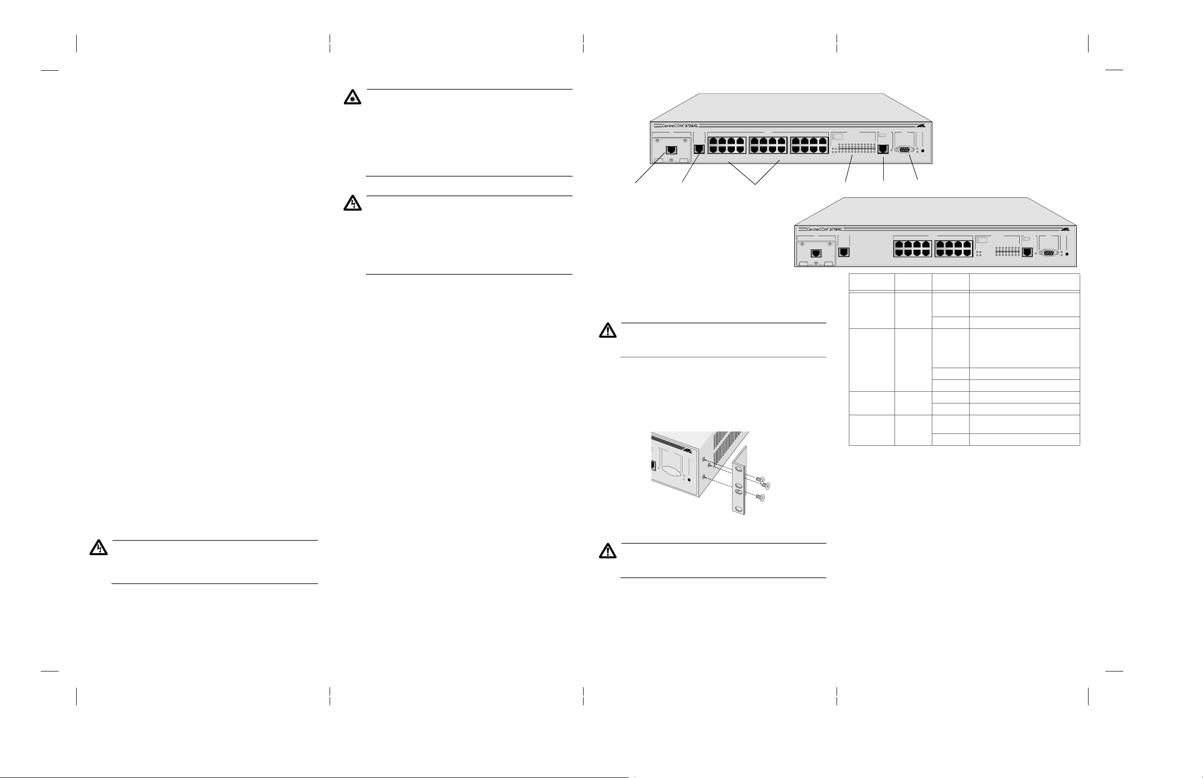
AT-3726XL Switch
5
10BASE-T ETHERNET SWITCH
with FAST ETHERNET 100BASE ACCESS
MDA
100BASE-TX MIRROR PORT RS-232
A
X
1X 3X 5X 7X
2X 4X 6X 8X
10Base-T Ports
10/100Base-TX
B
3701
100BASE-TX
X
10/100Base-TX
Full-duplex operation on both 10Base-T and 100Base-TX/FX ports
provide up to 200 Mbps of bandwidth to servers, routers, and other
switches.
Installing the Switch
Caution
Air vents must not be blocked and must have free access to the
room ambient air for cooling.
If desk-mounting the unit
1.
a level, secure desktop. Skip to Step 6.
If rack-mounting the unit,
2.
from the switch (if previously attached).
3. Remove the snap-on plastic feet.
4. Attach the rack-mounting brackets to each side of the switch,
using the 6 flathead screws provided.
R PORT
RS-232
TERMINAL PORT
STATUS
FAULT
POWER
5. Mount the unit in the rack.
6. Apply power to the unit as follows:
! 13
, make sure that the switch is placed on
remove all cables and power cord
RESET
Caution
The power cord is used as a disconnect device. To de-energize
equipment, disconnect the power cord.
Attach the power cord to the unit and plug it into the wall outlet.
Verify that the PWR LED lights green. See the LEDs table.
10BASE-T PORT ACTIVITY
9X 11X 13X 15X
10X 12X 14X 16X
17X 19X 21X 23X
18X 20X 22X 24X
AT-3716XL Switch
10BASE-T ETHERNET SWITCH
with FAST ETHERNET 100BASE ACCESS
MDA
B
3701
100BASE-TX
X
! 10
Terminal Default Settings
VT100
STATUS
X
Mirror Port
TERMINAL PORT
FAULT
POWER
RS232
1X 3X 5X 7X
2X 4X 6X 8X
8/N/1
Autobaud
RESET
Full-duplex
Use straight-through cable
10BASE-T PORT ACTIVITY
9X 11X 13X 15X
10X 12X 14X 16X
LINK LINK
ACTIVITY
1 3 5 7 9 11 13 15
2AB 4 6 8 10 12 14 16
LINK LINK
ACTIVITY
1 3 5 7 9 11 13 15 17 19 21 23
2AB 4 6 8 10 12 14 16 18 20 22 24
Port Activity
100BASE-TX MIRROR PORT RS-232
A
X
LED Color State Description
PWR (system) Green ON The switch is receiving power, voltage is
OFF No power.
FLT (system) Red ON The switch or management software is
OFF Normal operation.
Flashing Running diagnostics.
Link OK Green ON There is a physical link with a device.
OFF No link.
Activity Green Flashing The Ethernet port is receiving/transmitting
OFF No activity occurring on this port.
within the acceptable range, and the power
supply is working.
malfunctioning.
Note: If only the management software is
malfunctioning, the switch continues to
forward packets.
packets.
For troubleshooting techniques, see Chapter 3, Troubleshooting in the
AT-3726XL, AT-3716XL, and AT-3714FXL Installation Guide.
Setting Up Terminal for Local Management with Omega
1. For local management, connect your terminal to the RS232
connector on the switch’s front panel.
2. Access your terminal’s emulator program and set the terminal
settings as shown in the first figure.
3. Press
You are now ready to access the switch’s management software, Omega.
For remote management and further details concerning the Omega
management software, refer to the AT-S20 User’s Guide.
Return
several times to ensure baud configuration.
STATUS
TERMINAL PORT
FAULT
RESET
X
POWER
2 3 45
Page 2
Settings Default
IP Address 0.0.0.0
Subnet Mask 0.0.0.0
Gateway Address 0.0.0.0
Get community string public
Set community string private
Trap community string public
Port mirroring state Disabled
Spanning Tree Protocol Disabled
Telnet Access Enabled
System Name None
Password (Omega) No password assigned
Download Password ATS20
Port Priority 128
Port Path Cost 100
Half-duplex or Auto-negotiate (per port) Auto-negotiate (AT-3726XL, AT-3716XL)
High Speed Port Speed 100 Mbps
Spanning Tree Priority 32768
Active Aging Time 300 seconds
Hello Time 2 seconds
Transmit Pacing Disabled
Bridge Identifier (STP) 32768 (bridge priority)
Port Priority (STP) 128
Port Cost (STP) 100 for 10 Mbps ports
Store-and-forward or Cut-through
(fragment-free)
Domain name None
Timeout 5 minutes
Default VLAN Name Default VLAN
Half-duplex (AT-3714FXL)
10 for 100 Mbps ports
Store-and-forward
Caution
The RS232 port is for Setup and Diagnostics only. The cable
must be disconnected during normal operation to maintain
Emissions Compliance.
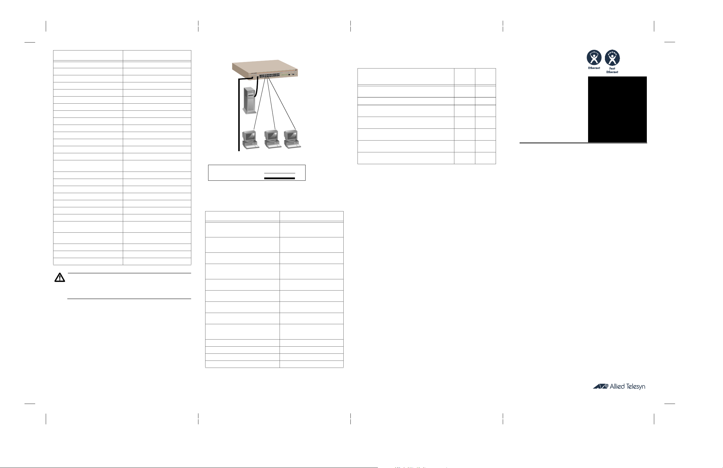
Workgroup Switch Configuration
This configuration shows the AT-3726XL switch used for a group of
heavy-traffic users in a large corporate network. In this example, the
switch is brought to the desktop with a single end-station per switch port.
A local server is connected to the 100 Mbps Fast Ethernet link and the
optional 100 Mbps port connects to the corporate ba ckbone.
Visit our technical publications website at:
www.alliedtelesyn.com
manuals.ht
STATUS
RS-232
MIRROR PORT
TERMINAL PORT
PORT ACTIVITY
10BASE-T
100BASE-TX
For 100 Mbps ports;
auto-negotiation
for 100Base-TX
Legend
Dedicated 10Mbps link
Dedicated 100Mbps link
MDA
B
A
Server
Uplink to corporate LAN
using MDA
AT-3726XL
Workstations
AT-3726XL, AT-3716XL, and AT-3714FXL
Related Guides
AT-3726XL, AT-3716XL, and AT-3714FXL Installation Guide,
613-10766-00 (shipped with product)
AT-S20 User’s Guide, 613-10716-00
AT- 3714FXL Quick Install Guide,
613-10767-00 (shipped with product)
AT-3714FXL Translated Safety Information Booklet,
613-10770-00 (shipped with product)
AT-3726XL and AT-3716XL Quick Install Guide,
613-10769-00 (shipped with product)
AT-3726XL and AT-3716XL Translated Safety Information
Booklet, 613-10768-00 (shipped with product)
AT-A10 and AT-A11 Quick Install Guide,
613-10742-00 (shipped with product)
Web Printed
✔
✔
✔
✔
✔
✔
✔
Where To Find Allied Teles yn and Technical Publications
Location Phone/Fax
Americas
U.S.A., Canada, Mexico, Central America, South
America
Asia
Singapore, Taiwan, Thailand, Malaysia,
Indonesia, Korea, Philippines, China, India
Australia
Australia, New Zealand
France
France, Belgium, Luxembourg, The Netherlands,
Middle East, Africa
Germany
Germany, Switzerland, Austria, Eastern Europe
Hong Kong (+852) 2-529-4111
Italy
Italy, Spain, Portugal, Greece, Turkey, Israel
Japan (+81) 3-3443-5640
United Kingdom
United Kingdom, Denmark, Norway, Sweden,
Finland, Iceland
Technical Bulletin Board 1-425-483-7979
Technical Support E-mail Address TS1@alliedtelesyn.com
CompuServe Go ALLIED
Internet, World Wide Web and FTP site http://www.alliedtelesyn.com
6 7 8
1 (800) 428-4835
1 (918) 628-3222
(+65) 3815-613
(+65) 3833-830
(+61) 2-9438-5111
(+61) 2-9438-4966
(+33) 1-60-92-15-32
(+33) 1-69-28-37-49
(+49) 30-435-900126
(+49) 30-435-70650
(+852) 2-529-7661
(+39) 2-416047
(+39) 2-419282
(+81) 3-3443-2443
(+44) 1-235-442560
(+44) 1-235-442490
Copyright 1998 Allied Telesyn International, Corp.
950 Kifer Road, Sunnyvale CA 94086 USA
All rights reserved. No part of this publication may be reproduced without prior written
permission from Allied Telesyn International, Corp.
COM is a registered trademark of Allied Telesyn International, Corp.
Centre
Ethernet is a registered trademark of Xerox Corporation. All other product names, company
names, logos or other designations mentioned herein are trademarks or registered trademarks of
their respective owners.
Allied Telesyn International, Corp. reserves the right to make changes in specifications and other
information contained in this document without prior written notice. The information provided
herein is subject to change without notice. In no event shall Allied Telesyn International, Corp. be
liable for any incidental, special, indirect, or consequential damages whatsoever, including but not
limited to lost profits, arising out of or related to this manual or the information contained herein,
even if Allied Telesyn International, Corp. has been advised of, known, or should have known, the
possibility of such damages.
QUICK
INSTALL
GUIDE
PN 613-10769-00 Rev. A
CentreCOM
AT-3 72 6 XL ,
AT-3 71 6 XL
Switches
®
 Loading...