

Page 1

PA Series
1kW Powered & Unpowered Audio Consoles
SERVICE INFORMATION
Publication AP5288
Page 2

Introduction
This publication provides technical information on servicing the Allen & Heath PA Series consoles.
Included are system block diagram, internal layout drawing and circuit schematics with board
layouts and spare parts lists. Whilst we believe this information to be reliable we do not assume
responsibility for inaccuracies. We also reserve the right to make changes in the interest of further
product development.
Additional Resources
Allen & Heath web site www.allen-heath.com Product information
Technical downloads
Distribution contacts
Company contacts
Technical support support@allen-heath.com
See web for local contact
Effects editor software PA-FX Editor Download from web site
PA-CP user guide AP4956 Operating instructions
Performance specification
PA user guide AP5195 Operating instructions
Performance specification
PA Series Service Information
Issue status: pa_series_ap5288_6.doc
Print date: 08 December 2004
Copyright © 2004 Allen & Heath. All rights reserved
Allen & Heath Limited
Kernick Industrial Estate, Penryn, Cornwall, TR10 9LU, UK
http://www.allen-heath.com
2 pa_series_ap5288_6.doc
Page 3

Servicing Precautions – General Notes
Service personnel: Service work should be carried out by technically qualified service personnel only.
Mains power is dangerous and can kill. Do not attempt to work on a linear or switched
mode power supply if you are not suitably qualified to do so. Do not attempt to repair
surface mount circuit assemblies unless you are suitably qualified and have the
necessary facilities to do so. Replacement circuit assemblies can be ordered.
Service facilities: Ensure a suitably sized work surface is available. Ensure this is clear of dirt, debris
and obstructions which may damage the equipment surfaces. Ensure adequate
lighting. Use the correct tools for the job and ensure they are in good working order.
Ensure all workshop safety requirements are adhered to.
Service information: Check that you have all the information you need before starting the service job. Refer
to the Allen & Heath web site or contact Allen & Heath technical support for details on
the latest information. Full technical information can be downloaded from the web site
Distributor Zone (password required).
Mains power: Connect the equipment to mains power only of the type described in the user guide
and marked on the rear panel. The power source must provide a good ground
connection. Ensure you always use an isolation transformer when working on any
mains power supply unit.
Mains cord and fuse: Use the correct power cord as supplied with the equipment. Do not remove or tamper
with the ground connection in the power cord. Heed the Important Mains Plug Wiring
Instructions printed in the user guide if it is necessary to rewire the mains cord.
Always replace the equipment mains fuse with the correct type and rating as
described in the user guide and marked on the equipment panel.
Opening the unit: Switch off and remove the mains power cord before opening the equipment. Ensure
all power supply covers and safety shields are in place before applying power with the
unit open for diagnostic fault finding.
Closing the unit: Before finishing, check the quality and accuracy of the service work carried out.
Remove any dirt or debris as this may cause equipment failure in the future. Ensure all
assemblies, harnesses and connectors are correctly aligned and plugged in. Ensure
that jumper settings and control configurations are correctly set according to the
requirements of the customer.
Testing the unit: Before operating the equipment, read and adhere to the Important Safety Instructions
printed in the user guide. Test that the service work has been successfully carried out.
Shipping the unit: Use adequate packing such as the original packaging or purpose designed flight case
if you need to ship the unit. To avoid injury to yourself or damage to the equipment
take care when lifting, moving or carrying the equipment.
Servicing Notes – PA-CP
User maintenance: There are no user serviceable parts inside. It should not be necessary for the user to
Technology:
remove the cover or access internal parts.
The PA-CP uses conventional thru-hole and SMT (surface mount) PCB technology. It
has a built-in linear regulated power supply which should be serviced by suitably
qualified personnel only.
Operation: To test the console make sure it is connected as described in the user guide. Check
that the voltage setting marked on the rear panel is correct for the local mains supply.
Fault finding: For effective fault diagnosis trace the signal flow through the circuit path. Refer to the
system block diagram. Replacement circuit assemblies are available from Allen &
Heath.
pa_series_ap5288_6.doc 3
Page 4

Contents Log
Internal Layout drawing ........................................... pa_series_layout_3.pdf
Surface and Main Parts.............................................. pa_series_parts_4.pdf
PA-CP System Block Diagram........................... pa-cp_blockdiagram_2.pdf
PA System Block Diagram...................................... pa_blockdiagram_2.pdf
PA-CP Mono Input Pcb.........................pa-cp_003-034_monoinput_1.1.pdf
PA Series Stereo Input PCB ..........pa_series_003-035_stereoinput_2.1.pdf
PA Series Aux / FX PCB...........................pa_series_003-036_auxfx_2.1.pdf
PA Series Sub 1 PCB............................... pa_series_003-037_sub1_1.1.pdf
PA Series FB1 / Phones PCB .........pa_series_003-038_fb1phones_2.1.pdf
PA Series FB2 PCB..................................... pa_series_003-039_fb2_1.1.pdf
PA-CP LR Master PCB ................................. pa-cp_003-040_lrmaster_3.pdf
PA-CP Distribution PCB .......................... pa-cp_003-041_distribution_2.pdf
PA Series Effects PCB ............................. pa_series_003-042_effects_2.pdf
PA-CP Amplifier PCB .................................. pa-cp_003-043_amplifier_4.pdf
PA-CP Power Supply PCB...................... pa-cp_003-069_linearpsu_3.2.pdf
PA-CP Power Supply PCB...................... pa-cp_003-069_linearpsu_3.3.pdf
PA Series FX LED PCB ............................ pa_series_003-070_fxled_2.1.pdf
PA Mono Input PCB ................................... pa_003-091_monoinput_1.2.pdf
PA LR Master PCB ............................................ pa_003-092_lrmaster_1.pdf
PA Distribution PCB ..................................... pa_003-093_distribution_1.pdf
PA Switched Mode Power Supply PCB ..............pa_003-094_smpsu_2.pdf
PA Switched Mode Power Supply PCB ..............pa_003-094_smpsu_4.pdf
4 pa_series_ap5288_6.doc
Page 5

PA Series – Historical Change Log
The following list identifies historical changes to the PA Series. The effective dates, serial
numbers and related change note documentation are included for reference to help identify
the correct issue circuit boards and components. Whilst we believe this information to be
reliable we do not assume responsibility for inaccuracies. We also reserve the right to make
changes in the interest of further product development.
Assembly Description
Main
003-094
003-069
003-094
003-034
Fader change to add extra master
fader
PA SMPSU PCB Minimum current
increase for TL783
PA-CP Linear PSU PCB +/- 15V rail
fuse value changes
PA SMPSU PCB post regulation
added – up-issue to issue 4
PA CP Mono Input 48V 22R type
change
From Serial
Number
019388
018930
018780
-
-
Date
16/06/03 917
23/09/03 949
23/09/03 950
13/11/03 966
25/02/04
Change Note
Number
990
pa_series_ap5288_6.doc 5
Page 6

PA Series Surface Parts
9MM POT NUT AB8050
GREY-RED KNOB AJ2074
14MM 5KRDx2 POT AI8174
GREY PUSH BUTTON AJ2864
LATCHING SWITCH AL0162
GREY-L/BLUE KNOB AJ2076
11MM 20KB C/D POT AI8004
GREY-GREEN KNOB AJ2077
11MM 200KCx2 POT AI8005
11MM 20KB C/D POT AI8004
11MM 20KB C/D POT AI8004
11MM 20KB C/D POT AI8004
GREY-GREY KNOB AJ2078
11MM 20KK POT AI8003
11MM 20KK POT AI8003
GREY-BLUE KNOB AJ2075
11MM 20KK POT AI8003
GREY-YELLOW KNOB AJ2079
11MM 20KK POT AI8003
GREY-BROWN KNOB AJ2080
14MM 10KACx2 C/D POT AI8008
RED TOMBSTONE LED AE4863
WHITE PUSH BUTTON AJ2962
LATCHING SWITCH AL0162
RED LED AE0086
ROUND GREY PUSH BUTTON AJ2864
LATCHING SWITCH AL0162
LINE
12kHz
250Hz
60Hz
MIC
-10 -5
FB1
FB2
AUX
PAN
-5
0
350Hz
0
20
10
100Hz
-15
1k5
-15 +15
-15
-15
O
O
O
OOO
O
O
=
-5
30
63 25
+15
7k
+15
+15
+6
+6
+6
+6
RL
-10
-20
-30
OO
-10
-20
-30
OO
-15 +15
-15
OO
OO
OO
OO
L R
0
14MM 20KKx2 POT AI8007
9-10
LR
5
10
LATCHING SWITCH AL0162
11MM 200KCx2 POT AI8005
11MM 20KB C/D POT AI8004
0
14MM 20KKx2 POT AI8007
5
10
11MM 200KCx2 POT AI8005
11MM 20KB C/D POT AI8004
14MM 20KBx2 C/D POT AI8006
-10
0
14MM 20KBx2 C/D POT AI8006
+15
11MM 20KK POT AI8003
+6
11MM 20KK POT AI8003
+6
11MM 20KK POT AI8003
+6
GREEN TOMBSTONE LED AE4864
11MM 20KK POT AI8003
+6
=
MOMENTARY SWITCH AL0374
14MM 10KACx2 C/D POT AI8008
LATCHING SWITCH AL0162
LATCHING SWITCH AL0162
14MM 20KKx2 POT AI 8007
11MM 20KK POT AI8003
11MM 20KK POT AI8003
M3x5 SCREW AB4661
LATCHING SWITCH AL0162
LATCHING SWITCH AL0162
STAGE
ROOM
HALL
PLATE
CHAMBER
CATHEDRAL
ARENA
GATED REV
PK !
3
O 10O
+6OO
+6
OO
KARAOKE
PING PONG
CHORUS
SLAP+REV
DLY+REV
ECHO+REV
CH+REV
PH+REV
70
10030
200
20Hz
+10
-10
70
100
30
200
20Hz
-10
12WAY LED BAR AE2701
4ABx5/16 SCREWAB0059
5MM RED LED AE0001
14MM 20KKx2 POT AI8007
LATCHING SWITCH AL0162
M3x5 SCREW AB4661
LATCHING SWITCH AL0162
LATCHING SWITCH AL0162
200
-10
120Hz
-10
500
500Hz120Hz
1k
500Hz
5k
10k
+10
-10
2k5
5k
10k
+10
-10
1k 1k200
2k
+10
500
1k
2k
+10+10
7k2k5
2k5
10k
1k5
-10
7k
2k5
1k5
MIN
20k
LIM
SIG
SPK
+10
OFF
TMP
SPK
OFF
SIG
LIM
20k
11MM 20KK POT AI8003
MAX
GREEN LED AE0085
LATCHING SWITCH AL0162
FB1
FB1L
YELLOW LED AE0084
FB2
L R+R
LATCHING SWITCH AL0162
11MM 20KK POT AI8003
MIN
+10
-10
MAX
BLUE LED AE4041
LATCHING SWITCH AL0162
11MM 20KK POT AI8003
+6OO
LATCHING SWITCH AL8065
POST-LR
LATCHING SWITCH AL8065
PRE-LR
TO
OOMAXMIN
14MM 20KKx2 POT AI8007
+6
GREEN TOMBSTONE LED AE4864
POST-LR FADER
LATCHING SWITCH AL0162
LATCHING SWITCH AL0162
10
40
50
3k600
12kHz
60Hz
PK !PK !
M3x5 SCREW AB4661
WHITE-BLACK FADER KNOB AJ8078
100MM 10KD FADER AI8117
BLUE-BLACK FADER KNOB AJ8081
100MM 10KDx2 FADER AI8118
YELLOW-BLACK FADER KNOB AJ8080
100MM 10KDx2 FADER AI8118
BLACK-WHITE FADER KNOB AJ3503
100MM 10KD FADER AI8117
PA series products up to serial
number 019388 have x1 stereo
MASTER LR FADER
PA series products from serial
number 019388 have x2 mono
MASTER L & R FADERS
RED-BLACK FADER KNOB AJ8079
100MM 10KDx2 FADER AI8118
RED-BLACK FADER KNOB AJ8079
100MM 10KD FADER AI8117
pa_series_parts_4.doc Sheet 1 of 2
Page 7
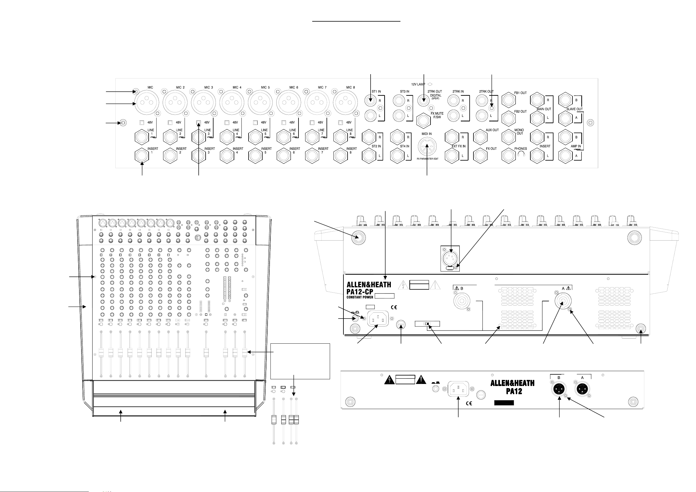
PA Series Surface Parts
A
4x5/16 SCREW AB2810
FEMALE XLR AL2412
M3x5 SCREW AB5344
1
JACK NUT AL4715
JACK SOCKET AL4713
LATCHING SWITCH AL0162
20DIA P4x5 FAST FOOT AK0102
5WAY FEMALE DIN SOCKET AL3962
M3x6 SCREW AB0072
SINGLE PHONO AL4895DUAL PHONO AL0577
4x5/16 SCREW AB2810
M3x10 SCREW AB0093 4PIN FEMALE XLR AL8104
M3x5 SCREW AB5344
SIDE MOULDIING AA4920-L/R
OR RACK EARS AA5013
HANDLE AA4922 FRONT EXTRUSION AA4923
M3x10 SCREW AB0076
BLACK BUTTON AJ2887
MAINS SWITCH
PA series products up to serial
number 019388 have x1 stereo
MASTER LR FADER
PA series products from serial
number 019388 have x2 mono
MASTER L & R FADERS
L3338
ON/OFF
0
I
ENGINEERED IN ENGLAND BY ALLEN & HEATH Ltd.
MAINS IEC AL5118
SERIAL NUMBER
MAINS INPUT
V AC ~ 47- 63 Hz
1600W MAX
FUSE HOLDER AL3178
10A FUSE AL3455
AVIS: RISQUE DE CHOC ELECTRIQUE - NE PAS OUVRIR.
DO NOT OBSTRUCT VENTILATION OPENINGS.
NO USER SERVICEABLE PARTS INSIDE.
WARNING: TO REDUCE THE RISK OF ELECTRIC SHOCK
DO NOT EXPOSE THIS APPARATUS TO RAIN OR MOISTURE.
THIS APPARATUS MUST BE EARTHED BY THE POWER CORD.
RISK OF HAZARDOUS ENERGY! MAKE PROPER SPEAKER CONNECTIONS.
SEE OPERATING MANUAL BEFORE USING.
CAUTION: FOR C ONTINUED PROTECTI ON AGAINST RISK OF FIRE
ATTENTION: REMPLACER LE FU SIBLE AVEC UN DES MEMES CARACTERISTIQUES.
100-240V T10A L
FUSE
CAUTION
RISK OF ELECTRIC SHOCK
DO NOT OPEN
AVIS: RISQUE DE CHOC ELECTRIQUE - NE PAS OUVRIR.
NO USER SERVICEABLE PARTS INSIDE.
WARNING: TO REDUCE THE RISK OF ELECTRIC SHOCK
DO NOT EXPOSE THIS APPARATUS TO RAIN OR MOISTURE.
THIS APPARATUS MUST BE EARTHED BY THE POWER CORD.
SEE OPERATING MANUAL BEFORE USING.
CAUTION: FOR CONTINUED PROTECT ION AGAINST RISK OF FIRE
ATTENTION: REMPLACER LE FUSIBLE AVEC UN DES MEMES CARACTERISTIQUES.
CAUTION
RISK OF ELECTRIC SHOCK
DO NOT OPEN
CONSTANT POWER SW ITCH
12V LAMP
REPLACE FUSE WITH SAME TYPE AND RATING.
8 OHMS4 OHMS
SET SWITCH TO MATCH SPEAKER IMPEDANCE
SPEAKER OUTPUTS
500W + 500W RMS
4 OHM LOAD MINIMUM
CONNECT SPEAKER BETWEEN PIN 1+ AND PIN 1-
SLIDE SWITCH AL5071 SPEAKON CONNECTOR AL8126
ON/OFF
I 0
REPLACE FUSE WITH SAME TYPE AND RATING.
75W MAX
FUSE
100-240V T1A L
SERIAL NUMBER
ENGINEERED IN ENGLAND BY ALLEN & HEATH Ltd.
MAINS INPUT
100 - 240 V AC ~ 47- 63 Hz
MAINS IEC AL3458
M3x10 SCREW AB0093
MAIN OUTPUT
BALANCED PIN2 = +
15DIA 9MM HIGH FAST FOOT AK5069M4x8 SCREW AB0332
MALE XLR AL2411 4x5/16 SCREW AB2810
pa_series_parts_4.doc Sheet 2 of 2
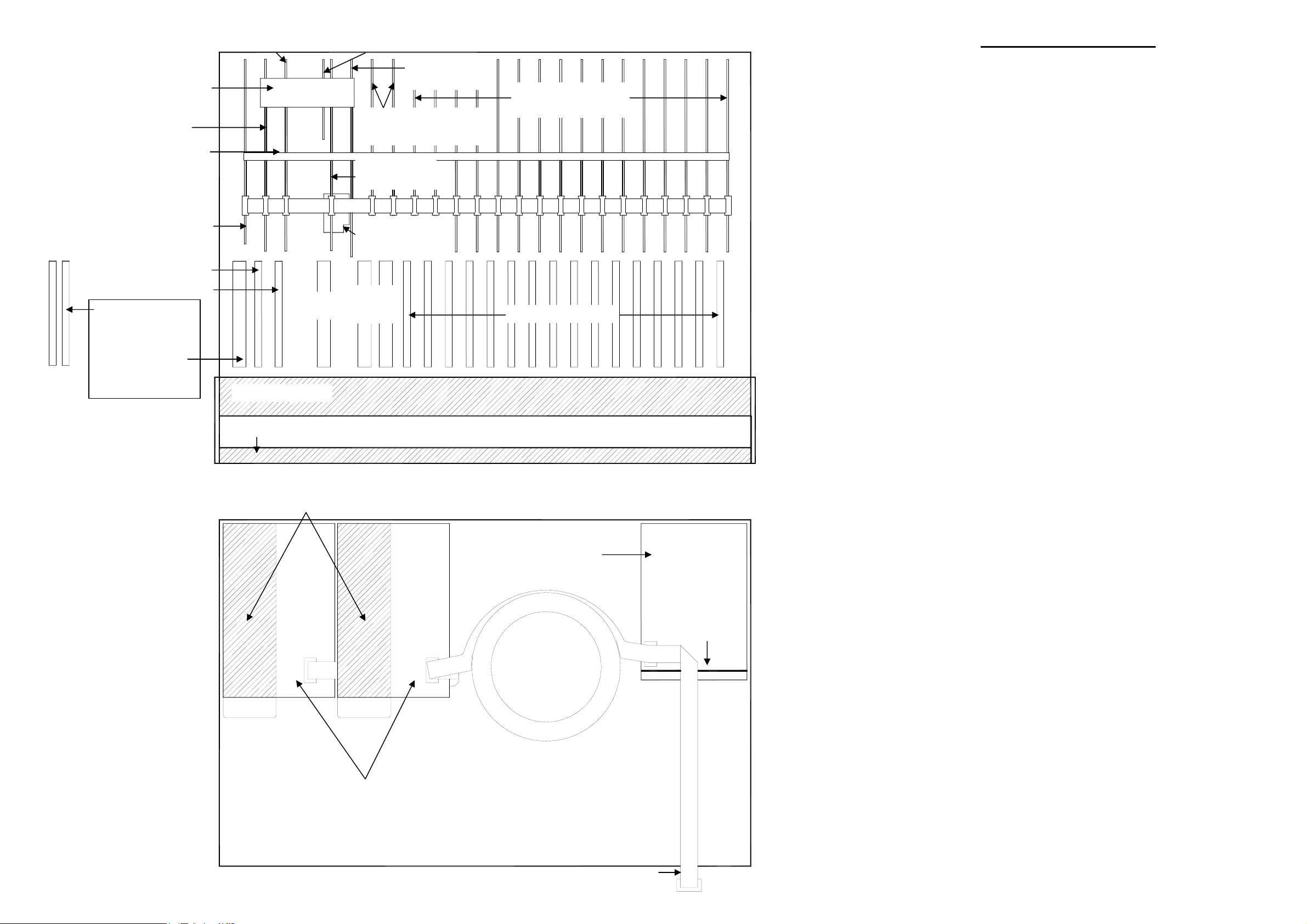
Page 8
)
FB1 PHONES PCB
003-038
SUB 1 PCB
003-037
PA-CP Powered version
DISTRIBUTION PCB
003-041
FB2 PCB
003-039
COPPER EARTH STRIP
L/R MASTER PCB
003-040
FB2 FADER
FB1 PHONES FADER
PA series products from
serial number 019388
have x2 mono MASTER
L & R FADERS
PA series products up
to serial number 019388
have x1 stereo
MASTER LR FADER
AL4875
AUX FX
FADER
FRONT EXTRUSION
EFFECTS PCB
003-042
STEREO INPUT PCBs
003-035 x 2
AUX FX PCB
-
FX LED PCB
003-070
STEREO
INPUT
FADERS
MONO INPUT PCBs
003-034 x 16
MONO INPUT FADERS
Product .............................PA12-CP/100
.........................................PA12-CP/120
.........................................PA12-CP/220
.........................................PA12-CP/240
.........................................PA20-CP/100
.........................................PA20-CP/120
.........................................PA20-CP/220
.........................................PA20-CP/240
PA12-CP Pack Assembly......... 003-030
PA12-CP Main Assembly ......... 003-031
PA12-CP Top Panel Assy. ....... 003-032
PA12-CP Base Panel Assy. ..... 003-033
PA12-CP Rack Ear Assy.......... 003-071
PA20-CP Pack Assy................. 003-083
HANDLE
PA-CP Front Panel assembly Front view (20ch. shown
AMPLIFIER HEATSINK x2
LINEAR PSU PCB
003-069
TRANSFORMER
FAN FAN
LINEAR PSU
HEATSINK
PA20-CP Main Assy................. 003-084
PA20-CP Top Panel Assy. ....... 003-085
PA20-CP Base Panel Assy. ..... 003-086
Mono Input PCB ....................... 003-034
Stereo Input PCB ..................... 003-035
Aux FX PCB ............................. 003-036
Sub 1 PCB................................ 003-037
FB1 Phones PCB ..................... 003-038
FB2 PCB .................................. 003-039
Master L/R PCB ....................... 003-040
Distribution PCB ....................... 003-041
Effects PCB .............................. 003-042
Amplifier PCB ........................... 003-043
Linear PSU PCB....................... 003-069
AMPLIFIER PCB
003-043
FX LED PCB ............................ 003-070
AL4877
pa_series_layout_3.doc Sheet 1 of 2
PA-CP Chassis assembly Front view
Page 9

FB1 PHONES PCB
003-038
SUB 1 PCB
003-037
PA unpowered version
DISTRIBUTION PCB
003-093
FB2 PCB
003-039
COPPER EARTH STRIP
L/R MASTER PCB
003-092
FB2 FADER
FB1 PHONES FADER
PA series products from
serial number 019388
have x2 mono MASTER
L & R FADERS
PA series products up
to serial number 019388
have x1 stereo
MASTER LR FADER
AL4875
AUX FX
FADER
FRONT EXTRUSION
EFFECTS PCB
003-042
STEREO INPUT PCBs
003-035 x 2
AUX FX PCB
-
FX LED PCB
003-070
STEREO
INPUT
FADERS
MONO INPUT PCBs
003-091 x 16
MONO INPUT FADERS
Product ...................................PA12/100
...............................................PA12/120
...............................................PA12/220
...............................................PA12/240
...............................................PA20/100
...............................................PA20/120
...............................................PA20/220
...............................................PA20/240
...............................................PA28/100
...............................................PA28/120
...............................................PA28/220
...............................................PA28/240
PA12-CP Rack Ear Assy.......... 003-071
PA12 Top Panel Assy. ............. 003-095
PA12 Base Panel Assy. ........... 003-096
PA12 Pack Assembly ............... 003-097
HANDLE
PA Front Panel assembly Front view (20ch. shown)
DISTRIBUTION PCB
003-093
PSU ASSEMBLY
003-100
SM PSU PCB
003-094
PA12 Main Assembly ............... 003-098
PA PSU Assy. .......................... 003-100
PA20 Pack Assembly ............... 003-101
PA20 Main Assy. ...................... 003-102
PA20 Base Panel Assy. ........... 003-103
PA20 Top Panel Assy. ............. 003-104
PA28 Pack Assembly ............... 003-105
PA28 Main Assembly ............... 003-106
PA28 Base Panel Assy. ........... 003-107
PA28 Top Panel Assy. ............. 003-108
Stereo Input PCB ..................... 003-035
Aux FX PCB ............................. 003-036
PSU HEATSINK
Sub 1 PCB................................ 003-037
FB1 Phones PCB ..................... 003-038
FB2 PCB .................................. 003-039
Effects PCB .............................. 003-042
FX LED PCB ............................ 003-070
Mono Input PCB ....................... 003-091
Master L/R PCB ....................... 003-092
Distribution PCB ....................... 003-093
SM PSU PCB ........................... 003-094
PA Chassis assembly Front view
pa_series_layout_3.doc Sheet 2 of 2
Page 10

Products from serial number 019388
PA-CP SERIES BLOCK DIAGRAM
METERS
PFLFXAUX
FB2
FB1RL
PEAK
MUTE
PFL
FADER
PAN
PFL
MONITOR
LR / 2TRK
PFL/AFL
PHONES
L
R
HEADPHONES
MIC IN
PP
+
-
+48V
GAIN
LINE IN
MONO CHANNEL
HPF
100Hz
+
-
INSERT
4 BAND EQUALISER
LM HM HF
LF
ST1/3
ST2/4
EXT FX IN
L
R
L
R
L
R
INTERNAL FX
SELECT 1-16 / OFF
GAIN
SEL
CHAN
GAIN
GAIN
DIR OUT
FX
AUX
FB2
FB1
PEAK
MUTE
SUM
FADER
PFL
+
MUTE
FADER
SUM
SUM
BAL
+
+
FX
AUX
FB2
FB1
FB2
FB1
FB1
FB2
FADER
FADER
AUX
FX
LR
STEREO CHANNEL
2 BAND EQUALISER
SUM
+
LF
FX CHANNEL
SUM
+
FX MUTE FOOTSWITCH
+
SUM
PEAK
PFL
SUM
HF
L INSERT
R INSERT
AFL
MUTE
AFL
MUTE
2TRK IN
L
R
MAIN LR
FB1 OUT
FB2 OUT
AUX OUT
FX OUT
2TRK
FADERS
2TRK TO LR
BGM
SUM
+
SUM
+
SOURCE SELECT
SPK A SPK B
PRE POST
100Hz
ADC
MUTE
SUB
FB1LFB1
FB2R+L R
STANDBY
MONO
RELAY
SPDIF DIGITAL
2TRK OUT
L
ANALOG
R
LEV
LM HM HFLF
4 BAND EQUALISER
LM HM HF
LF
AMP A
LIMITER
SIGNAL
PROTECT
TEMP
PROTECT
SIGNAL
LIMITER
AMP B
L
MAIN OUT
R
MONO OUT
A
SLAVE OUT
B
LEV
A
AMP IN
LEV
B
pa-cp_blockdiagram_2.doc Sheet 1 of 1
8 OHM4 OHM
Page 11

Products from serial number 019388
PA SERIES BLOCK DIAGRAM
METERS
PFL
FX
AUX
FB2
FB1
R
L
PEAK
MUTE
PFL
FADER
PAN
PFL
MONITOR
LR / 2TRK
PFL/AFL
PHONES
L
R
HEADPHONES
MIC IN
PP
+
-
+48V
GAIN
LINE IN
MONO CHANNEL
HPF
100Hz
+
-
INSERT
4 BAND EQUALISER
LM HM HF
LF
ST1/3
ST2/4
EXT FX IN
DIR OUT
FX
AUX
FB2
FB1
PFL
PEAK
MUTE
SUM
FADER
PFL
+
MUTE
FADER
SUM
BAL
+
FX
AUX
FB2
FB1
FB1
FB2
AFL
FADER
AFL
FADER
L
R
L
R
L
R
GAIN
CHAN
GAIN
GAIN
LR
STEREO CHANNEL
2 BAND EQUALISER
SUM
+
LF
HF
SUM
PEAK
FX CHANNEL
SUM
+
L INSERT
R INSERT
MUTE
MUTE
2TRK IN
L
R
MAIN LR
FB1 OUT
FB2 OUT
2TRK
FADERS
2TRK TO LR
BGM
SUM
SUM
+
SOURCE SELECT
PRE POST
+
100Hz
ADC
MUTE
SUB
FB1LFB1
FB2R+L R
MONO
SPDIF DIGITAL
2TRK OUT
L
ANALOG
R
LEV
LM HM HFLF
4 BAND EQUALISER
LM HM HF
LF
A
L
MAIN OUT
R
MONO OUT
A
SLAVE OUT
B
LEV
INTERNAL FX
SELECT 1-16 / OFF
SEL
pa_blockdiagram_2.doc Sheet 1 of 1
FX MUTE FOOTSWITCH
+
+
SUM
SUM
FB2
FB1
AUX
FX
AUX OUT
FX OUT
A OUT B OUT
PEAK
SIGNAL
SIGNAL
PEAK
LEV
B
LEV
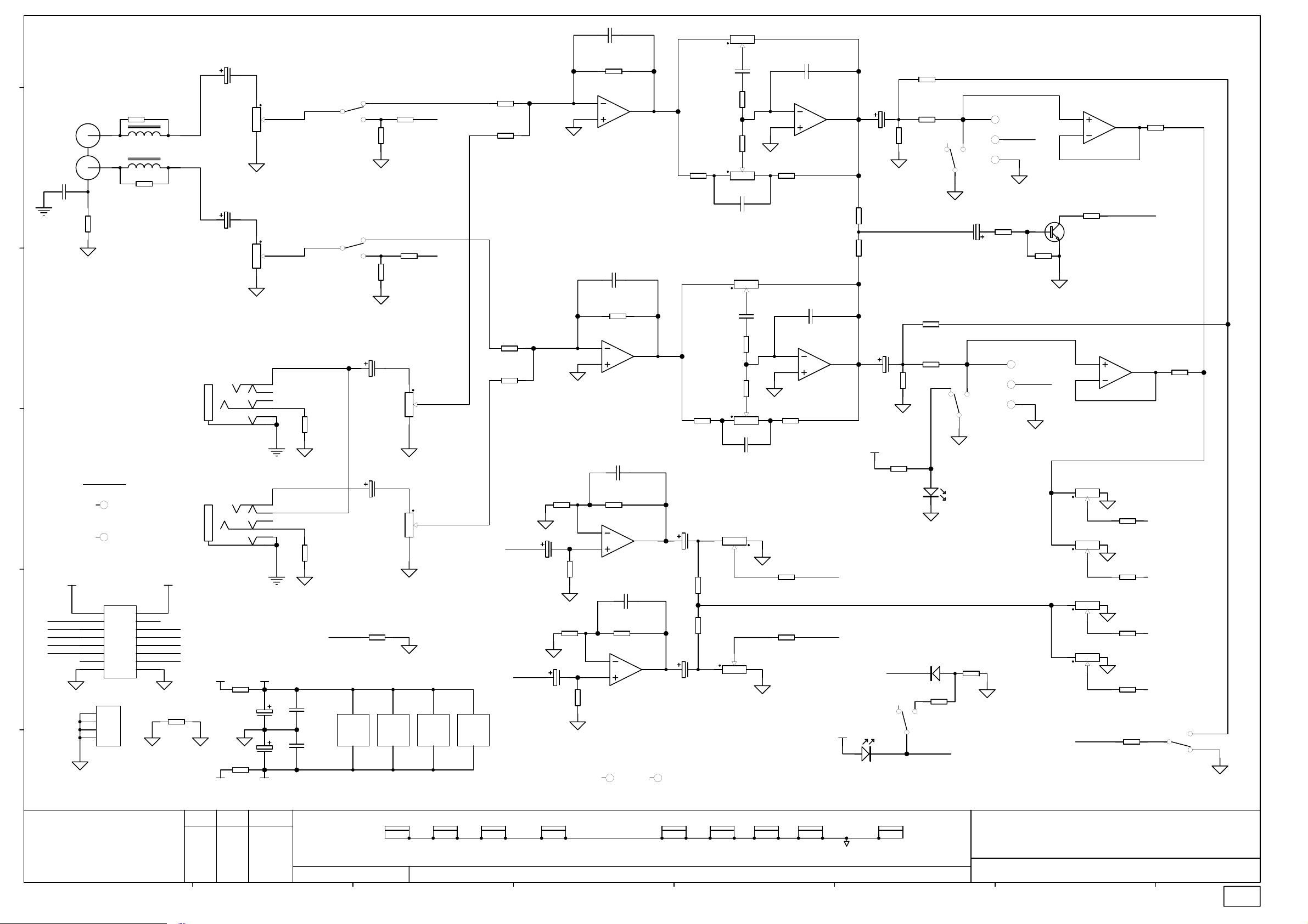
Page 12

SW1A
003-034/1
C2
47/63
C1
47/63
4
SW1B
6
SW2PCOL (SPUN)
1
3
R6
47K 0805
R5
47K 0805
-17VB
MIC-
D2
BAS16
-17VB
+48V
4K7 1% 0805 MELF
MIC+
D3
BAS16
R7
Q1
2SB737
R19
820R 1% 0805 MELF
1K2 1% 0805 MELF
R32
C6
1 6
220/10
POT14 5KRD X2
Q3
BC549
1K2 1% 0805 MELF
+17VB
VR1A
-17VB
4
Q4
BC549
R33
R21
68R 0805
820R 1% 0805 MELF
R8
4K7 1% 0805 MELF
MIC-
Q2
2SB737
R20
C11
33P 0805
C9
33P 0805
R22
2K7 1% 0805 MELF
U1B
6
5
NE5532 SMD
R23
2K7 1% 0805 MELF
LINE INPUT
CN2
JACK SLIMJACK SW6
C10
R
T
C15
R25
33K 1% 0805
47/25
C16
R24
33K 1% 0805
C18
7
47/25
R13
47K 0805
47/25
C12
15P 0805
15P 0805
R26
3K3 1% 0805
U1A
2
3
NE5532 SMD
R28
3K3 1% 0805
C7
220/10
R29
3K3 1% 0805
R27
3K3 1% 0805
3
R46
22R 0805
1
2 5
C17
47/25
VR1B
POT14 5KRD X2
AI1
HOLE-AI
FID1
FIDUCIAL
e
AI2
HOLE-AI
FID2
FIDUCIAL
3
1 2
0
R2
0R0 0805
CN1
XLR NC3FAHR20
C3
1N5_S
R1
0R0 0805
R10
1K8 0805
5
SW2PCOL (SPUN)
2
R4
6K8 1% 0805
R3
6K8 1% 0805
MIC INPUT
d
SW2A
SW2PCOL (SPUN)
1
3
C31
22N 0805
R67
0R0 0805
c
120K 1% 0805
C30
22N 0805
R47
100K 1% 0805
R31
R48
22K 0805
b
15
13
15
CN4
BOX 8X2 M 90 DEG
13
16
14
16
14
a
ALLEN&HEATH
Kernick Industrial Estate,
Penryn, Cornwall,
England. TR10 9LU
+44 (0)8707 556250
Tel:
+44 (0)8707 556251
Fax:
ABCDEFGH
2
R30
100K 1% 0805
Ground
PFL_DET
11
5
7
9
5
7
9
11
6
8812
10
6
12
10
PFL_BUS
FB1 FB2
AUX1 AUX2
MIXL MIXR
4
5
1 2
C28
R50
120K 1% 0805
2
3
V+ +17VB
1
3
1
3
2
4
2
4
V-
+48V
10R PF RAD
ISSUE BY DATE
A MG 25-02-02
B MG 03-05-02
C MG 25-06-02
1 MG 22-7-02
SW2B
6
SW2PCOL (SPUN)
C40
22N 0805
22P_S
U2A
TL072D SMD
R54
+17VA
10R PF RAD
C24
47/25
C25
47/25
R56
-17VA
C20
1
47/25
C38
100N 0805
C39
100N 0805
FILE: C4788_1P1.Sch 15:59:16 26-Mar-2003
JACK SLIMJACK SW6
CN3
R58
47R 0805
R14
47K 0805
R55
10R PF RAD
R57
10R PF RAD
VR1C
POT14 5KRD X2
BRKT
8
INSERT
-17VB
C26
47/25
C27
47/25
R
T
C21
47/25
9
VR2A
POT11 20KB C/D
R51
6K8 1% 0805
R59
82K 0805
R15
47K 0805
R39
12K 0805
C32
47N 0805
1 3
VR5A
POT11 20KB C/D
2
2
13
12kHz
C29
1N0 0805
U2B
6
5
TL072D SMD
R40
12K 0805
R16
47K 0805
250Hz
CN5
EARTH SCREW TERMINAL NARROW
1
2
3
4
6
VR3B
200KC X2 D/G
BRKT
5
6
VR2B
POT11 20KB C/D
BRKT
5
PRINTED:
7
C33
47N 0805
+17VA
C34
100N 0805
-17VA
VR4B
POT11 20KB C/D
BRKT
5
6
R68
2K7 0805
120Hz
R60
27K 0805
300 - 6kHz
R52
10K 1% 0805
C4
2N2_S
1 3
VR4A
POT11 20KB C/D
8
V+
V-
4
VR5B
POT11 20KB C/D
BRKT
5
6
C37
330N 0805
VR6A
POT11 20KB C/D
2
R11
1K8 0805
U3A
2
3
TL072D SMD
2
U1C
NE5532 SMD
VR6B
POT11 20KB C/D
BRKT
5
13
C13
33P 0805
1
3
6
2
8
V+
V-
4
R69
2K7 0805
1
C5
2N2_S
VR3A
POT11 200KC X2 D/G
R53
10K 1% 0805
U2C
TL072D SMD
VR7B
POT11 20KK
BRKT
5
6
VR8B
POT11 20KK
BRKT
5
PEAK
C22
47/25
8
V+
V-
U3C
TL072D SMD
4
6
PRE EQ
POST EQ
POST MUTE
+17VB
R17
47K 0805
3
1
C35
100N 0805
VR9B
POT11 20KK
BRKT
5
6
JP3
JUMP 2 STRT
1 2
JP1
1 2
JUMP 2 STRT
JP2
1 2
JUMP 2 STRT
LED RECT 5X2.5MM TOMB RED
SW3B
SW2PCOL (SPUN)
4
6
SW4A
SW2PCOL (SPUN)
VR10B
POT11 20KK
BRKT
5
R36
6K8 1% 0805
PIN-SOLDER 1.2MM
2
6
JP4
JUMP 2 SKT
C19
47/25
5
PIN-SOLDER 1.2MM
PIN-SOLDER 1.2MM
R49
22K 0805
VR11C
POT14 10KAC C/D
BRKT
8
R34
2K2 1% 0805
LD1
RED
GRN
BLU
PFL_BUS
+17VB
9
R9
0R0 0805
1
3
SW3A
SW2PCOL (SPUN)
2
R35
4K7 1% 0805
C23
47/25
SW4B
SW2PCOL (SPUN)
LD2
LED T1 3MM RED
VR7A
6
5
R18
47K 0805
PFL_DET
TITLE:
POT11 20KK
VR8A
POT11 20KK
R41
10K 1% 0805
U3B
TL072D SMD
4
5
13
R37
2
13
2
C14
33P 0805
7
VR11A
POT14 10KAC C/D
D1
BAS16
R61
6
22K 0805
R65
4K7 1% 0805
FB1
8K2 1% 0805
R38
FB2
8K2 1% 0805
PIN-WIRE CRIMP 1.0MM
C8
220/10
4
R12
3K3 1% 0805
DIR OUT FEED
P2
PIN-WIRE CRIMP 1.0MM
P1
16
POT14 10KAC C/D
2 5
C36
PEAK
47/25
VR9A
POT11 20KK
2
VR10A
POT11 20KK
2
VR11B
3
R64
47K 0805
5K6 0805
PA SERIES MONO INPUT
PAGE:
DRG No: ISSUE: SHEET: OF
C4788 1 1
1
13
R44
10K 1% 0805
13
R45
10K 1% 0805
R42
10K 1% 0805
R43
10K 1% 0805
R66
MIXR
MIXL
AUX1
AUX2
Q5
BC549
R63
0R0 0805
Page 13

003-034
Page 14

Note: Description includes Allen and Heath part number in brackets
)
)
)
)
)
)
)
)
)
)
)
Designator Description Designator Description
C1 CAPACITOR ELECTROLYTIC 47uF 63V (AF0217) R30 RESISTOR METAL FILM SMD0805 100K 1% (AC2843)
C2 CAPACITOR ELECTROLYTIC 47uF 63V (AF0217) R31 RESISTOR SMD 120K 1% 0805 (AC5109)
C3 CAPACITOR CERAMIC SMD0805 1N5 (AF2991) R32 RESISTOR SMD MELF 1K2 1% 0805 METAL (AC5039)
C4 CAPACITOR CERAMIC SMD0805 2N2 (AF3548) R33 RESISTOR SMD MELF 1K2 1% 0805 METAL (AC5039)
C5 CAPACITOR CERAMIC SMD0805 2N2 (AF3548) R34 RESISTOR METAL FILM SMD0805 2K2 1% (AC0370)
C6 CAPACITOR ELECTROLYTIC 220uF 10V (AF0225) R35 RESISTOR METAL FILM SMD0805 4K7 1% (AC3062)
C7 CAPACITOR ELECTROLYTIC 220uF 10V (AF0225) R36 RESISTOR METAL FILM SMD0805 6K8 1% (AC3064)
C8 CAPACITOR ELECTROLYTIC 220uF 10V (AF0225) R37 RESISTOR METAL FILM SMD0805 8K2 1% (AC5017)
C9 CAPACITOR SMD0805 33P XXV (AF4887) R38 RESISTOR METAL FILM SMD0805 8K2 1% (AC5017)
C10 CAPACITOR CERAMIC SMD0805 15P 50V (AF5034) R39 RESISTOR CARBON SMD0805 12K 5% (AC4107)
C11 CAPACITOR SMD0805 33P XXV (AF4887) R40 RESISTOR CARBON SMD0805 12K 5% (AC4107)
C12 CAPACITOR CERAMIC SMD0805 15P 50V (AF5034) R41 RESISTOR METAL FILM SMD0805 10K 1% (AC2841)
C13 CAPACITOR SMD0805 33P XXV (AF4887) R42 RESISTOR METAL FILM SMD0805 10K 1% (AC2841)
C14 CAPACITOR SMD0805 33P XXV (AF4887) R43 RESISTOR METAL FILM SMD0805 10K 1% (AC2841)
C15 CAPACITOR ELECTROLYTIC 47uF 25V (AF0208) R44 RESISTOR METAL FILM SMD0805 10K 1% (AC2841)
C16 CAPACITOR ELECTROLYTIC 47uF 25V (AF0208) R45 RESISTOR METAL FILM SMD0805 10K 1% (AC2841)
C17 CAPACITOR ELECTROLYTIC 47uF 25V (AF0208) R46 RESISTOR SMD 22R 5% 0805 (AC4100)
C18 CAPACITOR ELECTROLYTIC 47uF 25V (AF0208) R47 RESISTOR METAL FILM SMD0805 100K 1% (AC2843)
C19 CAPACITOR ELECTROLYTIC 47uF 25V (AF0208) R48 RESISTOR CARBON SMD0805 22K 5% (AC3540)
C20 CAPACITOR ELECTROLYTIC 47uF 25V (AF0208) R49 RESISTOR CARBON SMD0805 22K 5% (AC3540)
C21 CAPACITOR ELECTROLYTIC 47uF 25V (AF0208) R50 RESISTOR SMD 120K 1% 0805 (AC5109)
C22 CAPACITOR ELECTROLYTIC 47uF 25V (AF0208) R51 RESISTOR METAL FILM SMD0805 6K8 1% (AC3064)
C23 CAPACITOR ELECTROLYTIC 47uF 25V (AF0208) R52 RESISTOR METAL FILM SMD0805 10K 1% (AC2841)
C24 CAPACITOR ELECTROLYTIC 47uF 25V (AF0208) R53 RESISTOR METAL FILM SMD0805 10K 1% (AC2841)
C25 CAPACITOR ELECTROLYTIC 47uF 25V (AF0208) R54 RESISTOR CARBON 10R PRE FORMED 1/4W 5% (AC0378)
C26 CAPACITOR ELECTROLYTIC 47uF 25V (AF0208) R55 RESISTOR CARBON 10R PRE FORMED 1/4W 5% (AC0378)
C27 CAPACITOR ELECTROLYTIC 47uF 25V (AF0208) R56 RESISTOR CARBON 10R PRE FORMED 1/4W 5% (AC0378)
C28 CAPACITOR SMD 22P CERAMIC 0805 (AF2992) R57 RESISTOR CARBON 10R PRE FORMED 1/4W 5% (AC0378)
C29 CAPACITOR CERAMIC SMD0805 1N0 (AF5040) R58 RESISTOR CARBON SMD0805 47R 5% (AC3036)
C30 CAPACITOR CERAMIC SMD0805 22N (AF5035) R59 RESISTOR CARBON SMD0805 82K 5% (AC4894)
C31 CAPACITOR CERAMIC SMD0805 22N (AF5035) R60 RESISTOR CARBON SMD0805 27K 5% (AC4693)
C32 CAPACITOR SMD0805 47N XXV CERAMIC (AF4889) R61 RESISTOR CARBON SMD0805 22K 5% (AC3540)
C33 CAPACITOR SMD0805 47N XXV CERAMIC (AF4889) R63 RESISTOR CARBON SMD0805 0R0 5% (AC2838)
C34 CAPACITOR CERAMIC SMD0805 100N (AF2851) R64 RESISTOR CARBON SMD0805 47K 5% (AC3035)
C35 CAPACITOR CERAMIC SMD0805 100N (AF2851) R65 RESISTOR METAL FILM SMD0805 4K7 1% (AC3062)
C36 CAPACITOR ELECTROLYTIC 47uF 25V (AF0208) R66 RESISTOR CARBON SMD0805 5K6 5% (AC4106)
C37 CAPACITOR CERAMIC SMD0805 330N (AF5070) R67 RESISTOR METAL FILM SMD0805 10K 1% (AC2841)
C38 CAPACITOR CERAMIC SMD0805 100N (AF2851) R68 RESISTOR CARBON SMD0805 2K7 5% (AC4698)
C39 CAPACITOR CERAMIC SMD0805 100N (AF2851) R69 RESISTOR CARBON SMD0805 2K7 5% (AC4698)
C40 CAPACITOR CERAMIC SMD0805 22N (AF5035) SW1 SWITCH DPDT ALPS (SPUN) LATCHING (AL0162)
CN1 XLR 3 PIN FEMALE WITH GROUND (AL2412) SW2 SWITCH DPDT ALPS (SPUN) LATCHING (AL0162)
CN2 JACK SOCKET HORIZONTAL 6 PIN MET HEADPHONE (AL4713) SW3 SWITCH DPDT ALPS (SPUN) LATCHING (AL0162)
CN3 JACK SOCKET HORIZONTAL 6 PIN MET HEADPHONE (AL4713) SW4 SWITCH DPDT ALPS (SPUN) LATCHING (AL0162)
CN4 Connector IDC,Molex Type 0.1 Pitch 8x2 pins (AL4335)" U1 IC SMD NE5532 OP AMP (AE4699)
CN5 EARTH SCREW TERMINAL NARROW HORIZONTAL TYPE (AA9000) U2 IC SMD DUAL OP-AMP TL072 (AE3335)
D1 DIODE SIGNAL SMD BAS16 (AE3352) U3 IC SMD DUAL OP-AMP TL072 (AE3335)
D2 DIODE SIGNAL SMD BAS16 (AE3352) VR1 POT ALPS 14mm 5KRD x2 502RD (AI8174
D3 DIODE SIGNAL SMD BAS16 (AE3352) VR2 POT ALPS 11mm 20KB C/D 203B (AI8004
JP1 JUMP 2 OPTION LINK (AL8068) VR3 POT ALPS 11mm 200KC X2 DUAL GANG 204C (AI8005)
JP2 JUMP 2 OPTION LINK (AL8068) VR4 POT ALPS 11mm 20KB C/D 203B (AI8004
JP2 JUMPER SKT TWO WAY (AL0334) VR5 POT ALPS 11mm 20KB C/D 203B (AI8004
JP3 JUMP 2 OPTION LINK (AL8068) VR6 POT ALPS 11mm 20KB C/D 203B (AI8004
LD1 LED RED 5X2.5 TOMBSTONE (AE4863) VR7 POT ALPS 11mm 20KK 203K (AI8003
LD2 LED T1 3mm RED (AE0086
Q1 TRANSISTOR PNP 2SB737 (AE8069) VR9 POT ALPS 11mm 20KK 203K (AI8003
Q2 TRANSISTOR PNP 2SB737 (AE8069) VR10 POT ALPS 11mm 20KK 203K (AI8003
Q3 TRANSISTOR NPN BC549 (AE0020) VR11 POT ALPS 14mm 10KAC x2 C/D 103AC (AI8008
Q4 TRANSISTOR NPN BC549 (AE0020)
Q5 TRANSISTOR NPN BC549 (AE0020)
R1 RESISTOR SMD 22R 5% 0805 (AC4100)
R2 RESISTOR SMD 22R 5% 0805 (AC4100)
R3 RESISTOR METAL FILM SMD0805 6K8 1% (AC3064)
R4 RESISTOR METAL FILM SMD0805 6K8 1% (AC3064)
R5 RESISTOR CARBON SMD0805 47K 5% (AC3035)
R6 RESISTOR CARBON SMD0805 47K 5% (AC3035)
R7 RESISTOR SMD MELF 4K7 1% 0805 (AC5038)
R8 RESISTOR SMD MELF 4K7 1% 0805 (AC5038)
R9 RESISTOR CARBON SMD0805 0R0 5% (AC2838)
R10 RESISTOR CARBON SMD0805 1K8 5% (AC3029)
R11 RESISTOR CARBON SMD0805 1K8 5% (AC3029)
R12 RESISTOR METAL FILM SMD0805 3K3 1% (AC3061)
R13 RESISTOR CARBON SMD0805 47K 5% (AC3035)
R14 RESISTOR CARBON SMD0805 47K 5% (AC3035)
R15 RESISTOR CARBON SMD0805 47K 5% (AC3035)
R16 RESISTOR CARBON SMD0805 47K 5% (AC3035)
R17 RESISTOR CARBON SMD0805 47K 5% (AC3035)
R18 RESISTOR CARBON SMD0805 47K 5% (AC3035)
R19 RESISTOR SMD MELF 820R 1% 0805 METAL (AC5037)
R20 RESISTOR SMD MELF 820R 1% 0805 METAL (AC5037)
R21 RESISTOR CARBON SMD0805 68R 5% (AC4101)
R22 RESISTOR SMD MELF 2K7 1% 0805 (AC5108)
R23 RESISTOR SMD MELF 2K7 1% 0805 (AC5108)
R24 RESISTOR METAL FILM SMD0805 33K 1% (AC3532)
R25 RESISTOR METAL FILM SMD0805 33K 1% (AC3532)
R26 RESISTOR METAL FILM SMD0805 3K3 1% (AC3061)
R27 RESISTOR METAL FILM SMD0805 3K3 1% (AC3061)
R28 RESISTOR METAL FILM SMD0805 3K3 1% (AC3061)
R29 RESISTOR METAL FILM SMD0805 3K3 1% (AC3061)
VR8 POT ALPS 11mm 20KK 203K (AI8003
PA-CP Mono Input issue 1
Page 1 of 1
003−034
Page 15
CN1
003-035/1
RCA PHONO H2H
e
LEFT
RIGHT
C4
10N_S
IND EMI SUPP (WBCXX/R)
W
IND EMI SUPP (WBCXX/R)
R
R64
0R0 0805
d
c
GC
b
PFL_DET PFL_BUS
EARTH SCREW TERMINAL NARROW
AI HOLES
AI1
HOLE-AI
AI2
SLOT-AI
CN5
BOX 8X2 M 90 DEG
112
334
5
5
7
7
9
9
11
11
13
13
15
15
1
2
3
4
CN4
NF 0805
R3
R5 NF 0805
6
8
10
12
14
16
C20
33P 0805
C1
8
V+
V-
4
R27
10K 1% 0805
R26
10K 1% 0805
R32
10K 1% 0805
R31
10K 1% 0805
WIPER_L
WIPER_R
U6C
TL072D SMD
R6
4K7 1% 0805
C14
47/25
R7
4K7 1% 0805
C17
47/25
47/25
VR1A
POT14 20KK X2
L1
L2
C2
47/25
4
1 6
VR1B
POT14 20KK X2
3
2 5
SW1B
SW2PCOL (SPUN)
5
SW1A
SW2PCOL (SPUN)
2
4
R25
6
4K7 1% 0805
R1
NF 0805
1
R30
3
4K7 1% 0805
R2
NF 0805
C6
MIXL
MIXR
LEFT
T
R
CN3
JACK SLIMJACK MET SW6
R65
0R0 0805
47/25
C12
VR2A
POT14 20KK X2
4
1 6
RIGHT
T
R
CN2
JACK SLIMJACK MET SW6
V-V+
2
4
6
FB1FB2
8
AUXFX
10
MIXLMIXR
12
14
16
R70
10R PF RAD
10R PF RAD
R71
+17VA
-17VA
C15
47/25
C16
47/25
V+
R8
TCW
V-
R66
0R0 0805
C34
100N_S
C35
100N_S
GC
47/25
R46
0R0 0805
8
U3C
V+
V-
TL072D SMD
4
VR2B
POT14 20KK X2
2 5
8
U4C
V+
V-
TL072D SMD
4
3
8
U5C
V+
V-
TL072D SMD
4
6
5
2
3
2
3
R21
47K 0805
R22
47K 0805
R28
33K 1% 0805
U3B
TL072D SMD
C22
33P 0805
R33
33K 1% 0805
U3A
TL072D SMD
C24
R35
10K 1% 0805
U5A
TL072D SMD
C25
R36
10K 1% 0805
U5B
6
5
TL072D SMD
FID1
FIDUCIAL
7
33P 0805
33P 0805
1
1
7
FID2
FIDUCIAL
R14
C32
220/10
C33
220/10
3K9 0805
VR3B
POT14 20KB X2 C/D
3
R55
6K8 1% 0805
R10
3K9 0805
1 6
R50
2K2 1% 0805
R49
2K2 1% 0805
VR9B
POT14 10KAC C/D
3
VR4B
POT14 20KB X2 C/D
VR3A
POT14 20KB X2 C/D
VR4A
POT14 20KB X2 C/D
C30 150N 0805
VR9A
POT14 10KAC C/D
4
3
25
C31
2N7_S
R59
5K6 0805
25
C28 150N 0805
16
4
C3
2N7_S
R57
5K6 0805
R60
6K8 1% 0805
4
16
25
C26
22P_S
U4A
2
3
TL072D SMD
R43
3K9 0805
C29
22P_S
U4B
6
5
TL072D SMD
R44
3K9 0805
R37
8K2 1% 0805
R38
8K2 1% 0805
7
LD2
+17VA
SW4B
C5
47/25
C10
47/25
R61
6K8 1% 0805
PFL_DET
4
R11
47K 0805
R15
47K 0805
LD1
5
1
R68
1K0 1% 0805
R69
1K0 1% 0805
LED RECT 5X2.5MM TOMB RED
MIXL
MIXR
SW2PCOL (SPUN)
+17VA
LED T1 3MM RED
R62
3K3 1% 0805
R45
2K2 1% 0805
1
SW3A
SW2PCOL (SPUN)
R63
3K3 1% 0805
R48
2K2 1% 0805
D1
BAS16
6
R72
22K 0805
PEAK_LED
PIN-SOLDER 1.2MM
3
2
C11
47/25
4
6
SW3B
SW2PCOL (SPUN)
5
R74
3K3 1% 0805
P4
P6
WIPER_L
P5
R16
47K 0805
PIN-SOLDER 1.2MM
P1
P3
P2
R67
5K6 0805
WIPER_R
3
2
R4
4K7 1% 0805
Q1
BC848B
5
6
VR5A
POT11 20KK
2
VR6A
POT11 20KK
2
VR7A
POT11 20KK
2
VR8A
POT11 20KK
2
PFL_BUS
1
U6A
TL072D SMD
PEAK_LED
U6B
TL072D SMD
13
R40
10K 1% 0805
13
R41
10K 1% 0805
13
R39
6K8 1% 0805
13
R42
6K8 1% 0805
R73
22K 0805
R75
1K0 1% 0805
R76
1K0 1% 0805
7
FB1
FB2
AUX
FX
2
SW4A
SW2PCOL (SPUN)
3
1
a
ALLEN&HEATH
Kernick Industrial Estate,
Penryn, Cornwall,
England. TR10 9LU
+44 (0)8707 556250
Tel:
+44 (0)8707 556251
Fax:
ABCDEFGH
ISSUE BY DATE
1 MG 23-07-02
2 AAT 25-09-02
BRKT
8
VR1C
POT14 20KK X2
FILE: C4789_2.Sch 16:54:05 26-Mar-2003
BRKT
9
8
VR2C
POT14 20KK X2
PRINTED:
BRKT
9
8
VR3C
POT14 20KB X2 C/D
9
BRKT
8
9
VR4C
POT14 20KB X2 C/D
BRKT
5
6
VR5B
POT11 20KK
BRKT
5
VR6B
POT11 20KK
6
POT11 20KK
BRKT
5
VR7B
6
5
VR8B
POT11 20KK
BRKT
6
POT_GND
BRKT
8
9
VR9C
POT14 10KAC C/D
TITLE:
PA SERIES STEREO INPUT CCT
PAGE:
DRG No: ISSUE: SHEET: OF
AG4789 1 1
2
Page 16

003-035
Page 17

Note: Description includes Allen and Heath part number in brackets
)
)
)
)
)
)
)
)
)
)
)
Designator Description Designator Description
C1 CAPACITOR ELECTROLYTIC 47uF 25V (AF0208) R74 RESISTOR METAL FILM SMD0805 3K3 1% (AC3061)
C2 CAPACITOR ELECTROLYTIC 47uF 25V (AF0208) R75 RESISTOR METAL FILM SMD0805 1K0 1% (AC0369)
C3 CAPACITOR CERAMIC SMD0805 2N7 (AF2993) R76 RESISTOR METAL FILM SMD0805 1K0 1% (AC0369)
C4 CAPACITOR SMD 10N CERAMIC 0805 (AF2849) SW1 SWITCH DPDT ALPS (SPUN) LATCHING (AL0162)
C5 CAPACITOR ELECTROLYTIC 47uF 25V (AF0208) SW3 SWITCH DPDT ALPS (SPUN) LATCHING (AL0162)
C6 CAPACITOR ELECTROLYTIC 47uF 25V (AF0208) SW4 SWITCH DPDT ALPS (SPUN) LATCHING (AL0162)
C10 CAPACITOR ELECTROLYTIC 47uF 25V (AF0208) U3 IC SMD DUAL OP-AMP TL072 (AE3335)
C11 CAPACITOR ELECTROLYTIC 47uF 25V (AF0208) U4 IC SMD DUAL OP-AMP TL072 (AE3335)
C12 CAPACITOR ELECTROLYTIC 47uF 25V (AF0208) U5 IC SMD DUAL OP-AMP TL072 (AE3335)
C14 CAPACITOR ELECTROLYTIC 47uF 25V (AF0208) U6 IC SMD DUAL OP-AMP TL072 (AE3335)
C15 CAPACITOR ELECTROLYTIC 47uF 25V (AF0208) VR1 POT ALPS 14mm 20KK x2 203K (AI8007
C16 CAPACITOR ELECTROLYTIC 47uF 25V (AF0208) VR2 POT ALPS 14mm 20KK x2 203K (AI8007
C17 CAPACITOR ELECTROLYTIC 47uF 25V (AF0208) VR3 POT ALPS 14mm 20KB x2 C/D 203B (AI8006
C20 CAP SM 33pF (AF4887) VR4 POT ALPS 14mm 20KB x2 C/D 203B (AI8006
C22 CAP SM 33pF (AF4887) VR5 POT ALPS 11mm 20KK 203K (AI8003
C24 CAP SM 33pF (AF4887) VR6 POT ALPS 11mm 20KK 203K (AI8003
C25 CAP SM 33pF (AF4887) VR7 POT ALPS 11mm 20KK 203K (AI8003
C26 CAPACITOR CERAMIC SMD0805 22P (AF2992) VR8 POT ALPS 11mm 20KK 203K (AI8003
C28 CAPACITOR CERAMIC SMD 150nF 25V (AF4888) VR9 POT ALPS 14mm 10KAC x2 C/D 103AC (AI8008
C29 CAPACITOR CERAMIC SMD0805 22P (AF2992)
C30 CAPACITOR CERAMIC SMD 150nF 25V (AF4888)
C31 CAPACITOR CERAMIC SMD0805 2N7 (AF2993)
C32 CAPACITOR ELECTROLYTIC 220uF 10V (AF0225)
C33 CAPACITOR ELECTROLYTIC 220uF 10V (AF0225)
C34 CAPACITOR CERAMIC SMD0805 100N (AF2851)
C35 CAPACITOR CERAMIC SMD0805 100N (AF2851)
CN1 RCA PHONO DUAL HORIZONTAL R/W (AL0577)
CN2 JACK SOCKET HORIZONTAL 6 PIN MET HEADPHONE (AL4713)
CN3 JACK SOCKET HORIZONTAL 6 PIN MET HEADPHONE (AL4713)
CN4 EARTH SCREW TERMINAL NARROW HORIZONTAL TYPE (AA9000)
CN5 Connector IDC,Molex Type 0.1 Pitch 8x2 pins (AL4335)
D1 DIODE SIGNAL SMD BAS16 (AE3352)
LD1 LED RECT 5x2.5MM TOMBSTONE RED (AE4863
LD2 LED T1 3mm RED (AE0086
Q1 TRANSISTOR NPN BC848B (AE3332)
R3 RESISTOR CARBON SMD0805 0R0 5% (AC2838)
R4 RESISTOR METAL FILM SMD0805 4K7 1% (AC3062)
R5 RESISTOR CARBON SMD0805 0R0 5% (AC2838)
R6 RESISTOR METAL FILM SMD0805 4K7 1% (AC3062)
R7 RESISTOR METAL FILM SMD0805 4K7 1% (AC3062)
R8 TC LINK 22SWG (AH0070)
R10 RESISTOR CARBON SMD0805 3K9 5% (AC4105)
R11 RESISTOR CARBON SMD0805 47K 5% (AC3035)
R14 RESISTOR CARBON SMD0805 3K9 5% (AC4105)
R15 RESISTOR CARBON SMD0805 47K 5% (AC3035)
R16 RESISTOR CARBON SMD0805 47K 5% (AC3035)
R21 RESISTOR CARBON SMD0805 47K 5% (AC3035)
R22 RESISTOR CARBON SMD0805 47K 5% (AC3035)
R25 RESISTOR METAL FILM SMD0805 4K7 1% (AC3062)
R26 RESISTOR METAL FILM SMD0805 10K 1% (AC2841)
R27 RESISTOR METAL FILM SMD0805 10K 1% (AC2841)
R28 RESISTOR METAL FILM SMD0805 33K 1% (AC3532)
R30 RESISTOR METAL FILM SMD0805 4K7 1% (AC3062)
R31 RESISTOR METAL FILM SMD0805 10K 1% (AC2841)
R32 RESISTOR METAL FILM SMD0805 10K 1% (AC2841)
R33 RESISTOR METAL FILM SMD0805 33K 1% (AC3532)
R35 RESISTOR METAL FILM SMD0805 10K 1% (AC2841)
R36 RESISTOR METAL FILM SMD0805 10K 1% (AC2841)
R37 RESISTOR METAL FILM SMD0805 8K2 1% (AC5017)
R38 RESISTOR METAL FILM SMD0805 8K2 1% (AC5017)
R39 RESISTOR METAL FILM SMD0805 6K8 1% (AC3064)
R40 RESISTOR METAL FILM SMD0805 10K 1% (AC2841)
R41 RESISTOR METAL FILM SMD0805 10K 1% (AC2841)
R42 RESISTOR METAL FILM SMD0805 6K8 1% (AC3064)
R43 RESISTOR CARBON SMD0805 3K9 5% (AC4105)
R44 RESISTOR CARBON SMD0805 3K9 5% (AC4105)
R45 RESISTOR METAL FILM SMD0805 2K2 1% (AC0370)
R46 RESISTOR METAL FILM SMD0805 10K 1% (AC2841)
R48 RESISTOR METAL FILM SMD0805 2K2 1% (AC0370)
R49 RESISTOR METAL FILM SMD0805 2K2 1% (AC0370)
R50 RESISTOR METAL FILM SMD0805 2K2 1% (AC0370)
R55 RESISTOR METAL FILM SMD0805 6K8 1% (AC3064)
R57 RESISTOR CARBON SMD0805 5K6 5% (AC4106)
R59 RESISTOR CARBON SMD0805 5K6 5% (AC4106)
R60 RESISTOR METAL FILM SMD0805 6K8 1% (AC3064)
R61 RESISTOR METAL FILM SMD0805 6K8 1% (AC3064)
R62 RESISTOR METAL FILM SMD0805 3K3 1% (AC3061)
R63 RESISTOR METAL FILM SMD0805 3K3 1% (AC3061)
R64 RESISTOR CARBON SMD0805 0R0 5% (AC2838)
R65 RESISTOR CARBON SMD0805 0R0 5% (AC2838)
R66 RESISTOR CARBON SMD0805 0R0 5% (AC2838)
R67 RESISTOR CARBON SMD0805 5K6 5% (AC4106)
R68 RESISTOR METAL FILM SMD0805 1K0 1% (AC0369)
R69 RESISTOR METAL FILM SMD0805 1K0 1% (AC0369)
R70 RESISTOR CARBON 10R PRE FORMED 1/4W 5% (AC5077)
R71 RESISTOR CARBON 10R PRE FORMED 1/4W 5% (AC5077)
R72 RESISTOR CARBON SMD0805 22K 5% (AC3540)
R73 RESISTOR CARBON SMD0805 22K 5% (AC3540)
PA-CP Stereo Input issue 2
Page 1 of 1
003−035
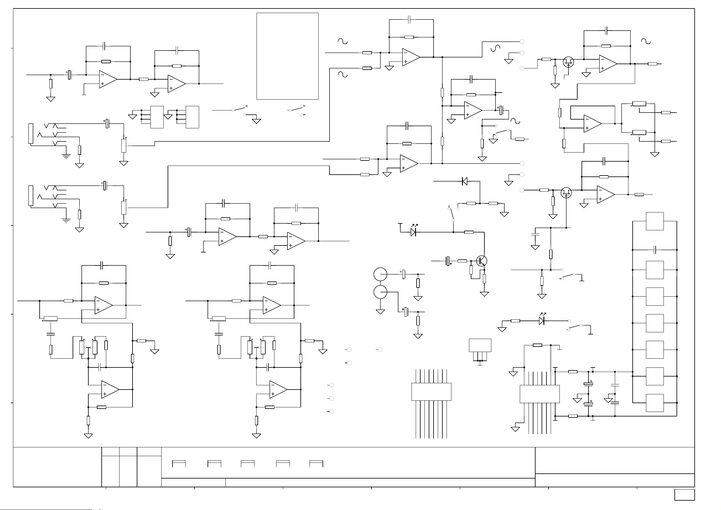
Page 18
C6
003-036/1
C1
100/6.3
e
FX
R1
100K 1% 0805
EXT FX LEFT
CN3
JACK SLIMJACK SW6
T
R
EXT FX RIGHT
d
CN2
JACK SLIMJACK SW6
T
R
c
2
C28
47N 0805
R48
15K 0805
R42
10K 1% 0805
13
POT11 200KC X2 D/G
LF_IN_A
VR2A
POT11 20KB C/D
b
a
ALLEN&HEATH
Kernick Industrial Estate,
Penryn, Cornwall,
England. TR10 9LU
+44 (0)8707 556250
Tel:
+44 (0)8707 556251
Fax:
ABCDEFGH
6
5
GC
R34
68R 0805
R35
68R 0805
2
3
VR1A
2
1
R58
10K 1% 0805
C3
22P_S
R4
20K 1% 0805
7
U1B
TL072D SMD
C14
47/25
VR5A
POT14 20KK X2
1 6
C16
47/25
VR5B
POT14 20KK X2
2 5
C12
22P_S
R43
10K 1% 0805
1
U6A
TL072D SMD
3
R49
15K 0805
C26
47N 0805
6
5
TL072D SMD
R62
6K8 1% 0805
ISSUE BY DATE
7
U6B
A MG 25-02-02
B AAT 30-04-02
1 AAT 04-07-02
2 AAT 09-09-02
C4
22P_S
R7
R6
10K 1% 0805
CN8
1
2
3
4
EARTH SCREW TERMINAL NARROW
4
3
AUX
LF_OUT_A
R60
3K3 1% 0805
R56
10K 1% 0805
10K 1% 0805
6
5
U2B
TL072D SMD
CN9
1
2
3
4
EARTH SCREW TERMINAL NARROW
C2
R2
100/6.3
100K 1% 0805
LF_IN_B
VR1B
POT11 200KC X2 D/G
BRKT
5
6
FILE: C4790_2.1.SCH 09:14:03 27-Mar-2003
7
ENCODER
GC
POT11 20KB C/D
FX_OUT
SW3A
FX_SW
2
SW2PCOM (SPUN)
C9
22P_S
R5
20K 1% 0805
2
3
U1A
TL072D SMD
R44
VR4A
POT11 20KB C/D
VR2B
BRKT
5
10K 1% 0805
13
2
C29
47N 0805
R50
15K 0805
POT11 200KC X2 D/G
6
PRINTED:
EFFECTS PCB
1
3
R12
1
10K 1% 0805
C13
22P_S
R45
10K 1% 0805
U7A
2
3
TL072D SMD
VR3A
POT11 200KC X2 D/G
VR3B
BRKT
5
2
1
6
3
C27
47N 0805
U7B
6
5
R63
6K8 1% 0805
R59
10K 1% 0805
SW3B
5
SW2PCOM (SPUN)
C10
22P_S
R13
10K 1% 0805
2
3
TL072D SMD
1
R51
15K 0805
7
TL072D SMD
VR4B
POT11 20KB C/D
BRKT
5
6
U2A
R61
3K3 1% 0805
R57
10K 1% 0805
FROM_FX_L
4
6
FROM_FX_R
1
LF_OUT_B
VR5C
POT14 20KK X2
BRKT
8
9
33K 1% 0805
AUX_OUT
RCA PHONO H2H
FID1
FIDUCIAL
FID3
FIDUCIAL
AI1
HOLE-AI VTECH
AI2
SLOT-AI VTECH
AI3
SLOT-AI VTECH
R8
33K 1% 0805
R19
10K 1% 0805
R14
R20
10K 1% 0805
CN1
2
3
TL072D SMD
6
5
TL072D SMD
+17VA
C18
47/25
W
R
FID2
FIDUCIAL
TO DIST PCB
22P_S
R23
33K 1% 0805
U3A
C5
22P_S
R24
33K 1% 0805
U3B
LD2
LED T1 3MM RED
C19
47/25
15
15
16
16
FX_SW
1
R25
22K 1% 0805
R28
22K 1% 0805
7
PFL_DET
SW2B
SW2PCOL (SPUN)
C17
PEAK
2TRK_IN_L
R39
47K 0805
2TRK_IN_R
R40
47K 0805
13
11
13
14
14
12
FROM_FX_L FROM_FX_R
47/25
LF_OUT_BLF_IN_B
3
5
7
9
3
5
7
9
11
4
6
8812
10
4
6
10
FX_OUT AUX_OUT
LF_IN_A LF_OUT_A
FOOTSWITCH
C7
22P_S
R26
22K 1% 0805
6
5
U4B
TL072D SMD
47K 0805
D1
BAS16
R41
4
6
22K 0805
R21
5
4K7 1% 0805
R36
47K 0805
R52
5K6 0805
CN7
EARTH SCREW TERMINAL NARROW
1
CN5
1
BOX 8X2 M 90 DEG
2
2
2TRK_IN_L 2TRK_IN_R
R37
3K3 1% 0805
123
SGND
BOX 8X2 M 90 DEG
PEAK
C15
47/25
7
3
1
SW2A
SW2PCOL (SPUN)
R46
Q3
BC549
R55
0R0 0805
4
MAIN BUS
CN6
P1
RED
P2
GRN
P3
BLU
2
R38
47K 0805
P4
PNK
P5
GRN2
P6
VIO
C22
100N_S
FOOTSWITCH
100K 1% 0805
R22
6K8 1% 0805
LED RECT 5X2.5MM TOMB RED
15
16
R9
10K 1% 0805
22K 1% 0805
22K 1% 0805
PFL_BUS
22K 1% 0805
R16
10K 1% 0805
R15
22K 1% 0805
R47
470K 2% 0805
R3
LD1
R18
NF 0805
PFL_DET
13
11
7
9
7
9
15
13
11
16
14
8812
10
14
12
10
PFL_BUS
AUX FX
MIXL MIXR
R10
R27
5
6
FB1 FB2
3
5
6
4
+48V
R29
V+
3
4
V-
TITLE:
PAGE:
DRG No: ISSUE: SHEET: OF
C8
22P_S
2
3
6
5
5
-17VA
+17VA
-17VA
R30
33K 1% 0805
TL072D SMD
U4A
C11
22P_S
R31
33K 1% 0805
TL072D SMD
C20
47/25
C21
47/25
1
U5B
U5A
1
7
C24
100N_S
C25
100N_S
R11
10K 1% 0805
VR7A
POT11 20KK
2
VR8A
POT11 20KK
2
R17
10K 1% 0805
U7C
8
TL072D SMD
U1C
8
TL072D SMD
U2C
8
TL072D SMD
U3C
8
TL072D SMD
U4C
8
TL072D SMD
U5C
8
TL072D SMD
U6C
8
TL072D SMD
13
13
MIXR
V+
100N_S
V+
V+
V+
V+
V+
V+
Q1
J111N
MUTE
Q2
J111N
MUTE
SW1A
SW2PCOL (SPUN)
3
1
SW1B
SW2PCOL (SPUN)
6
4
GC
R53
10R PF RAD
1
1
2
2
R54
10R PF RAD
2
3
TL072D SMD
2
-17VA
PA SERIES AUX-FX PCB
C4790 1 1
2.1
V-
C23
V-
V-
V-
V-
V-
V-
MIXL
R32
12K 0805
R33
12K 0805
4
4
4
4
4
4
4
FB1
FB2
Page 19

003-036
Page 20

Note: Description includes Allen and Heath part number in brackets
)
)
)
)
)
)
)
Designator Description Designator Description
C1 CAPACITOR ELECTROLYTIC 100uF 6.3V (AF2984) R47 RESISTOR METAL FILM SMD0805 470K 2% (AC2844)
C2 CAPACITOR ELECTROLYTIC 100uF 6.3V (AF2984) R48 RESISTOR CARBON SMD0805 15K 5% (AC3486)
C3 CAPACITOR CERAMIC SMD0805 22P (AF2992) R49 RESISTOR CARBON SMD0805 15K 5% (AC3486)
C4 CAPACITOR CERAMIC SMD0805 22P (AF2992) R50 RESISTOR CARBON SMD0805 15K 5% (AC3486)
C5 CAPACITOR CERAMIC SMD0805 22P (AF2992) R51 RESISTOR CARBON SMD0805 15K 5% (AC3486)
C6 CAPACITOR CERAMIC SMD0805 22P (AF2992) R52 RESISTOR CARBON SMD0805 5K6 5% (AC4106)
C7 CAPACITOR CERAMIC SMD0805 22P (AF2992) R53 RESISTOR CARBON 10R PRE FORMED 1/4W 5% (AC5077)
C8 CAPACITOR CERAMIC SMD0805 22P (AF2992) R54 RESISTOR CARBON 10R PRE FORMED 1/4W 5% (AC5077)
C9 CAPACITOR CERAMIC SMD0805 22P (AF2992) R55 RESISTOR CARBON SMD0805 0R0 5% (AC2838)
C10 CAPACITOR CERAMIC SMD0805 22P (AF2992) R56 RESISTOR METAL FILM SMD0805 10K 1% (AC2841)
C11 CAPACITOR CERAMIC SMD0805 22P (AF2992) R57 RESISTOR METAL FILM SMD0805 10K 1% (AC2841)
C12 CAPACITOR CERAMIC SMD0805 22P (AF2992) R58 RESISTOR METAL FILM SMD0805 10K 1% (AC2841)
C13 CAPACITOR CERAMIC SMD0805 22P (AF2992) R59 RESISTOR METAL FILM SMD0805 10K 1% (AC2841)
C14 CAPACITOR ELECTROLYTIC 47uF 25V (AF0208) R60 RESISTOR METAL FILM SMD0805 3K3 1% (AC3061)
C15 CAPACITOR ELECTROLYTIC 47uF 25V (AF0208) R61 RESISTOR METAL FILM SMD0805 3K3 1% (AC3061)
C16 CAPACITOR ELECTROLYTIC 47uF 25V (AF0208) R62 RESISTOR METAL FILM SMD0805 6K8 1% (AC3064)
C17 CAPACITOR ELECTROLYTIC 47uF 25V (AF0208) R63 RESISTOR METAL FILM SMD0805 6K8 1% (AC3064)
C18 CAPACITOR ELECTROLYTIC 47uF 25V (AF0208) SW1 SWITCH DPDT ALPS (SPUN) LATCHING (AL0162)
C19 CAPACITOR ELECTROLYTIC 47uF 25V (AF0208) SW2 SWITCH DPDT ALPS (SPUN) LATCHING (AL0162)
C20 CAPACITOR ELECTROLYTIC 47uF 25V (AF0208) SW3 SWITCH 2 POLE MOMENTARY (AL0374)
C21 CAPACITOR ELECTROLYTIC 47uF 25V (AF0208) U1 IC SMD DUAL OP-AMP TL072 (AE3335)
C22 CAPACITOR CERAMIC SMD0805 100N (AF2851) U2 IC SMD DUAL OP-AMP TL072 (AE3335)
C23 CAPACITOR CERAMIC SMD0805 100N (AF2851) U3 IC SMD DUAL OP-AMP TL072 (AE3335)
C24 CAPACITOR CERAMIC SMD0805 100N (AF2851) U4 IC SMD DUAL OP-AMP TL072 (AE3335)
C25 CAPACITOR CERAMIC SMD0805 100N (AF2851) U5 IC SMD DUAL OP-AMP TL072 (AE3335)
C26 CAPACITOR CERAMIC SMD0805 47N (AF4889) U6 IC SMD DUAL OP-AMP TL072 (AE3335)
C27 CAPACITOR CERAMIC SMD0805 47N (AF4889) U7 IC SMD DUAL OP-AMP TL072 (AE3335)
C28 CAPACITOR CERAMIC SMD0805 47N (AF4889) VR1 POT ALPS 11mm 200KC X2 DUAL GANG 204C (AI8005)
C29 CAPACITOR CERAMIC SMD0805 47N (AF4889) VR2 POT ALPS 11mm 20KB C/D 203B (AI8004
CN1 RCA PHONO DUAL HORIZONTAL R/W (AL0577) VR3 POT ALPS 11mm 200KC X2 DUAL GANG 204C (AI8005)
CN2 JACK SOCKET HORIZONTAL 6 PIN MET HEADPHONE (AL4713) VR4 POT ALPS 11mm 20KB C/D 203B (AI8004
CN3 JACK SOCKET HORIZONTAL 6 PIN MET HEADPHONE (AL4713) VR5 POT ALPS 14mm 20KK x2 203K (AI8007
CN5 Connector IDC,Molex Type 0.1 Pitch 8x2 pins (AL4335) VR7 POT ALPS 11mm 20KK 203K (AI8003
CN6 Connector IDC,Molex Type 0.1 Pitch 8x2 pins (AL4335) VR8 POT ALPS 11mm 20KK 203K (AI8003
CN7 EARTH SCREW TERMINAL NARROW HORIZONTAL TYPE (AA9000)
CN8 EARTH SCREW TERMINAL NARROW HORIZONTAL TYPE (AA9000)
CN9 EARTH SCREW TERMINAL NARROW HORIZONTAL TYPE (AA9000)
D1 DIODE SIGNAL SMD BAS16 (AE3352)
LD1 LED RECT 5x2.5MM TOMBSTONE RED (AE4863
LD2 LED T1 3mm RED (AE0086
Q1 TRANSISTOR JFET N CHANNEL J111N (AE0083)
Q2 TRANSISTOR JFET N CHANNEL J111N (AE0083)
Q3 TRANSISTOR NPN BC549 (AE0020)
R1 RESISTOR METAL FILM SMD0805 100K 1% (AC2843)
R2 RESISTOR METAL FILM SMD0805 100K 1% (AC2843)
R3 RESISTOR METAL FILM SMD0805 100K 1% (AC2843)
R4 RESISTOR METAL FILM SMD0805 20K 1% (AC5057)
R5 RESISTOR SMD 20K 1% 0805 (AC5057)
R6 RESISTOR METAL FILM SMD0805 10K 1% (AC2841)
R7 RESISTOR METAL FILM SMD0805 10K 1% (AC2841)
R8 RESISTOR METAL FILM SMD0805 33K 1% (AC3532)
R9 RESISTOR METAL FILM SMD0805 10K 1% (AC2841)
R10 RESISTOR METAL FILM SMD0805 22K 1% (AC2842)
R11 RESISTOR METAL FILM SMD0805 10K 1% (AC2841)
R12 RESISTOR METAL FILM SMD0805 10K 1% (AC2841)
R13 RESISTOR METAL FILM SMD0805 10K 1% (AC2841)
R14 RESISTOR METAL FILM SMD0805 33K 1% (AC3532)
R15 RESISTOR METAL FILM SMD0805 22K 1% (AC2842)
R16 RESISTOR METAL FILM SMD0805 10K 1% (AC2841)
R17 RESISTOR METAL FILM SMD0805 10K 1% (AC2841)
R19 RESISTOR METAL FILM SMD0805 10K 1% (AC2841)
R20 RESISTOR METAL FILM SMD0805 10K 1% (AC2841)
R21 RESISTOR METAL FILM SMD0805 4K7 1% (AC3062)
R22 RESISTOR METAL FILM SMD0805 6K8 1% (AC3064)
R23 RESISTOR METAL FILM SMD0805 33K 1% (AC3532)
R24 RESISTOR METAL FILM SMD0805 33K 1% (AC3532)
R25 RESISTOR METAL FILM SMD0805 22K 1% (AC2842)
R26 RESISTOR METAL FILM SMD0805 22K 1% (AC2842)
R27 RESISTOR METAL FILM SMD0805 22K 1% (AC2842)
R28 RESISTOR METAL FILM SMD0805 22K 1% (AC2842)
R29 RESISTOR METAL FILM SMD0805 22K 1% (AC2842)
R30 RESISTOR METAL FILM SMD0805 33K 1% (AC3532)
R31 RESISTOR METAL FILM SMD0805 33K 1% (AC3532)
R32 RESISTOR CARBON SMD0805 12K 5% (AC4107)
R33 RESISTOR CARBON SMD0805 12K 5% (AC4107)
R34 RESISTOR CARBON SMD0805 68R 5% (AC4101)
R35 RESISTOR CARBON SMD0805 68R 5% (AC4101)
R36 RESISTOR CARBON SMD0805 47K 5% (AC3035)
R37 RESISTOR CARBON SMD0805 47K 5% (AC3035)
R38 RESISTOR CARBON SMD0805 47K 5% (AC3035)
R39 RESISTOR CARBON SMD0805 47K 5% (AC3035)
R40 RESISTOR CARBON SMD0805 47K 5% (AC3035)
R41 RESISTOR CARBON SMD0805 22K 5% (AC3540)
R42 RESISTOR METAL FILM SMD0805 10K 1% (AC2841)
R43 RESISTOR METAL FILM SMD0805 10K 1% (AC2841)
R44 RESISTOR METAL FILM SMD0805 10K 1% (AC2841)
R45 RESISTOR METAL FILM SMD0805 10K 1% (AC2841)
R46 RESISTOR METAL FILM SMD0805 3K3 1% (AC3061)
PA-CP Aux FX issue 2
Page 1 of 1
003−036
Page 21

+17VB
003-037/1
3
U(S)1E
LM339 SMD
V+
V-
12
-17VB
R(S)4
e
1 2
SGNDS
120R 1% 0805
R(S)5
120R 1% 0805
R(S)6
120R 1% 0805
R(S)7
120R 1% 0805
R(S)8
120R 1% 0805
d
R(S)9
330R 1% 0805
R(S)10
330R 1% 0805
R(S)11
560R 1% 0805
R(S)12
680R 1% 0805
c
R(S)13
1K2 1% 0805
R(S)14
1K2 1% 0805
R(S)15
3K9 0805
R(S)16
1K0 1% 0805
b
+17VB
P8
1
1
PIN
P9
1
1
PIN
P10
-17VB
1
1
PIN
P11
1
1
PIN
SGNDS
12
12
12
12
1 2
1 2
1 2
1 2
1 2
1 2
1 2
1 2
+17VB
3
V+
V-
12
4
5
6
7
8
9
10
11
4
5
6
7
8
9
10
11
4
5
6
7
8
9
10
11
U(S)2E
LM339 SMD
U(S)1A
LM339 SMD
U(S)1B
U(S)1C
LM339 SMD
U(S)1D
LM339 SMD
U(S)2A
U(S)2B
LM339 SMD
U(S)2C
LM339 SMD
U(S)2D
LM339 SMD
U(S)3A
LM339 SMD
U(S)3B
LM339 SMD
U(S)3C
LM339 SMD
U(S)3D
LM339 SMD
3
U(S)3E
LM339 SMD
V+
V-
12
-17VB
2
1
LM339 SMD
14
13
2
LM339 SMD
1
14
13
2
1
14
13
R(S)3
15K 0805
+17VB
R(S)2
4K7 1% 0805
1 2
-17VB
1 2
123456789101112131415161718192021222324
METER SUB PCB
R(S)1
1K2 1% 0805
Q(S)1
BC858B
LD(S)1
LED BAR
CN1
RCA PHONO H2H
LF_OUT_A
R2
68R 0805
W
R3
68R 0805
R
R1
68R 0805
VR2A
POT11 20KB C/D
2
C9
6N8_S
R14
12K 0805
R24
+VA
10R PF RAD
R25
-VA
10R PF RAD
C1
2TRK_OUT_L
47/25
C2
2TRK_OUT_R
47/25
R8
10K 1% 0805
13
2
3
VR1A
POT11 200KC X2 D/G
2
+17VA
C5
47/25
C6
47/25
-17VA
TL072D SMD
3
C10
1
6N8_S
6
5
R20
10K 1% 0805
R18
15K 0805
100N 0805
EXT FX RIGHT
CN2
JACK SLIMJACK SW6
C7
22P_S
R9
10K 1% 0805
1
U1A
R15
12K 0805
U1B
TL072D SMD
C13
100N 0805
C14
T
R
R22
2K7 0805
R12
10K 1% 0805
7
8
U1C
TL072D SMD
V+
V-
4
LMF_OUT_A
8
U2C
TL072D SMD
V+
V-
4
R4
68R 0805
R5
68R 0805
C3
47/25
LF_OUT_B
JACK SLIMJACK SW6
VR4A
POT11 20KB C/D
2
C11
6N8_S
R16
12K 0805
TO DIST PCB
+VA
-VA
EXT FX LEFT
CN3
T
R
R10
10K 1% 0805
13
POT11 200KC X2 D/G
LMF_OUT_A
15
13
11
7
9
9
15
13
11
16
14
10
16
14
12
10
LF_OUT_A
VR3A
2
LMF_OUT_B
5
7
8812
6
LF_OUT_B
2
3
1
R19
15K 0805
1
3
3
5
4
6
2
4
2TRK_OUT_L 2TRK_OUT_R
FX_OUT AUX_OUT
1
2
R6
68R 0805
R7
68R 0805
C8
22P_S
R11
10K 1% 0805
U2A
1
TL072D SMD
3
R17
12K 0805
C12
6N8_S
U2B
6
5
TL072D SMD
R21
10K 1% 0805
CN4
BOX 8X2 M 90 DEG
AI1
HOLE-AI VTECH
AI1_1
HOLE-AI VTECH
C4
47/25
LMF_OUT_B
R23
2K7 0805
R13
10K 1% 0805
7
FH1
HOLE-FIXING 3.5MM
FH2
HOLE-FIXING 3.5MM
FID1
FIDUCIAL
AI2
SLOT-AI VTECH
FX_OUTAUX_OUT
FID2
FIDUCIAL
FID1_1
FIDUCIAL
a
ALLEN&HEATH
Kernick Industrial Estate,
Penryn, Cornwall,
England. TR10 9LU
+44 (0)8707 556250
Tel:
+44 (0)8707 556251
Fax:
ABCDEFGH
ISSUE BY DATE
A MG 25-02-02
B AAT 22-04-02
1 AAT 27-06-02
VR1B
POT11 200KC X2 D/G
BRKT
5
6
FILE: C4791_1P1.SCH 09:36:03 27-Mar-2003
VR2B
POT11 20KB C/D
BRKT
5
6
VR3B
POT11 200KC X2 D/G
BRKT
5
PRINTED:
6
VR4B
POT11 20KB C/D
BRKT
5
6
TITLE:
PA SERIES SUB 1 PCB
PAGE:
DRG No: ISSUE: SHEET: OF
C4791 1 1
1
Page 22

003-037
Page 23

Note: Description includes Allen and Heath part number in brackets
)
)
Designator Description
C1 CAPACITOR ELECTROLYTIC 47uF 25V (AF0208)
C2 CAPACITOR ELECTROLYTIC 47uF 25V (AF0208)
C3 CAPACITOR ELECTROLYTIC 47uF 25V (AF0208)
C4 CAPACITOR ELECTROLYTIC 47uF 25V (AF0208)
C5 CAPACITOR ELECTROLYTIC 47uF 25V (AF0208)
C6 CAPACITOR ELECTROLYTIC 47uF 25V (AF0208)
C7 CAPACITOR CERAMIC SMD0805 22P (AF2992)
C8 CAPACITOR CERAMIC SMD0805 22P (AF2992)
C9 CAPACITOR SMD 6N8 CERAMIC 0805 (AF2994)
C10 CAPACITOR SMD 6N8 CERAMIC 0805 (AF2994)
C11 CAPACITOR SMD 6N8 CERAMIC 0805 (AF2994)
C12 CAPACITOR SMD 6N8 CERAMIC 0805 (AF2994)
C13 CAPACITOR CERAMIC SMD0805 100N (AF2851)
C14 CAPACITOR CERAMIC SMD0805 100N (AF2851)
CN1 RCA PHONO DUAL HORIZONTAL R/W (AL0577)
CN2 JACK SOCKET HORIZONTAL 6 PIN MET HEADPHONE (AL4713)
CN3 JACK SOCKET HORIZONTAL 6 PIN MET HEADPHONE (AL4713)
CN4 Connector IDC,Molex Type 0.1 Pitch 8x2 pins (AL4335)
LD(S)1 LED BAR MB12 SQUARE LEDS IN HOUSING 8G,3Y,1R (AE2701)
Q(S)1 TRANSISTOR PNP BC858B (AE3042)
R1 RESISTOR CARBON SMD0805 68R 5% (AC4101)
R2 RESISTOR CARBON SMD0805 68R 5% (AC4101)
R3 RESISTOR CARBON SMD0805 68R 5% (AC4101)
R4 RESISTOR CARBON SMD0805 68R 5% (AC4101)
R5 RESISTOR CARBON SMD0805 68R 5% (AC4101)
R6 RESISTOR CARBON SMD0805 68R 5% (AC4101)
R7 RESISTOR CARBON SMD0805 68R 5% (AC4101)
R8 RESISTOR METAL FILM SMD0805 10K 1% (AC2841)
R9 RESISTOR METAL FILM SMD0805 10K 1% (AC2841)
R10 RESISTOR METAL FILM SMD0805 10K 1% (AC2841)
R11 RESISTOR METAL FILM SMD0805 10K 1% (AC2841)
R12 RESISTOR METAL FILM SMD0805 10K 1% (AC2841)
R13 RESISTOR METAL FILM SMD0805 10K 1% (AC2841)
R14 RESISTOR CARBON SMD0805 12K 5% (AC4107)
R15 RESISTOR CARBON SMD0805 12K 5% (AC4107)
R16 RESISTOR CARBON SMD0805 12K 5% (AC4107)
R17 RESISTOR CARBON SMD0805 12K 5% (AC4107)
R18 RESISTOR CARBON SMD0805 15K 5% (AC3486)
R19 RESISTOR CARBON SMD0805 15K 5% (AC3486)
R20 RESISTOR METAL FILM SMD0805 10K 1% (AC2841)
R21 RESISTOR METAL FILM SMD0805 10K 1% (AC2841)
R22 RESISTOR CARBON SMD0805 2K7 5% (AC4698)
R23 RESISTOR CARBON SMD0805 2K7 5% (AC4698)
R24 RESISTOR CARBON 10R PRE FORMED 1/4W 5% (AC5077)
R25 RESISTOR CARBON 10R PRE FORMED 1/4W 5% (AC5077)
R(S)1 RESISTOR METAL FILM SMD0805 1K2 1% (AC3059)
R(S)2 RESISTOR METAL FILM SMD0805 4K7 1% (AC3062)
R(S)3 RESISTOR CARBON SMD0805 15K 5% (AC3486)
R(S)4 RESISTOR METAL FILM SMD0805 120R 1% (AC3055)
R(S)5 RESISTOR METAL FILM SMD0805 120R 1% (AC3055)
R(S)6 RESISTOR METAL FILM SMD0805 120R 1% (AC3055)
R(S)7 RESISTOR METAL FILM SMD0805 120R 1% (AC3055)
R(S)8 RESISTOR METAL FILM SMD0805 120R 1% (AC3055)
R(S)9 RESISTOR METAL FILM SMD0805 330R 1% (AC3056)
R(S)10 RESISTOR METAL FILM SMD0805 330R 1% (AC3056)
R(S)11 RESISTOR METAL FILM SMD0805 560R 1% (AC3057)
R(S)12 RESISTOR METAL FILM SMD0805 680R 1% (AC3058)
R(S)13 RESISTOR METAL FILM SMD0805 1K2 1% (AC3059)
R(S)14 RESISTOR METAL FILM SMD0805 1K2 1% (AC3059)
R(S)15 RESISTOR CARBON SMD0805 3K9 5% (AC4105)
R(S)16 RESISTOR METAL FILM SMD0805 1K0 1% (AC0369)
U1 IC SMD DUAL OP-AMP TL072 (AE3335)
U2 IC SMD DUAL OP-AMP TL072 (AE3335)
U(S)1 IC LM339 COMPARATOR SMD (AE4890)
U(S)2 IC LM339 COMPARATOR SMD (AE4890)
U(S)3 IC LM339 COMPARATOR SMD (AE4890)
VR1 POT ALPS 11mm 200KC X2 DUAL GANG 204C (AI8005)
VR2 POT ALPS 11mm 20KB C/D 203B (AI8004
VR3 POT ALPS 11mm 200KC X2 DUAL GANG 204C (AI8005)
VR4 POT ALPS 11mm 20KB C/D 203B (AI8004
PA-CP Sub 1 issue 1
Page 1 of 1
003−037
Page 24

+17VB
003-037/1
3
U(S)1E
LM339 SMD
V+
V-
12
-17VB
R(S)4
e
1 2
SGNDS
120R 1% 0805
R(S)5
120R 1% 0805
R(S)6
120R 1% 0805
R(S)7
120R 1% 0805
R(S)8
120R 1% 0805
d
R(S)9
330R 1% 0805
R(S)10
330R 1% 0805
R(S)11
560R 1% 0805
R(S)12
680R 1% 0805
c
R(S)13
1K2 1% 0805
R(S)14
1K2 1% 0805
R(S)15
3K9 0805
R(S)16
1K0 1% 0805
b
+17VB
P8
1
1
PIN
P9
1
1
PIN
P10
-17VB
1
1
PIN
P11
1
1
PIN
SGNDS
12
12
12
12
1 2
1 2
1 2
1 2
1 2
1 2
1 2
1 2
+17VB
3
V+
V-
12
4
5
6
7
8
9
10
11
4
5
6
7
8
9
10
11
4
5
6
7
8
9
10
11
U(S)2E
LM339 SMD
U(S)1A
LM339 SMD
U(S)1B
U(S)1C
LM339 SMD
U(S)1D
LM339 SMD
U(S)2A
U(S)2B
LM339 SMD
U(S)2C
LM339 SMD
U(S)2D
LM339 SMD
U(S)3A
LM339 SMD
U(S)3B
LM339 SMD
U(S)3C
LM339 SMD
U(S)3D
LM339 SMD
3
U(S)3E
LM339 SMD
V+
V-
12
1K 1% 0805
-17VB
2
1
LM339 SMD
14
13
2
LM339 SMD
1
14
13
2
1
14
13
R(S)2
R(S)3
15K 0805
1 2
+17VB
1 2
123456789101112131415161718192021222324
-17VB
METER SUB PCB
R(S)1
180R 0805
Q(S)1
BC858B
LD(S)1
LED BAR
CN1
RCA PHONO H2H
LF_OUT_A
R2
68R 0805
W
R3
68R 0805
R
R1
68R 0805
VR2A
POT11 20KB C/D
2
C9
6N8_S
R14
12K 0805
R24
+VA
10R PF RAD
R25
-VA
10R PF RAD
C1
2TRK_OUT_L
47/25
C2
2TRK_OUT_R
47/25
R8
10K 1% 0805
13
2
3
VR1A
POT11 200KC X2 D/G
2
+17VA
C5
47/25
C6
47/25
-17VA
TL072D SMD
3
C10
1
6N8_S
6
5
R20
10K 1% 0805
R18
15K 0805
100N 0805
EXT FX RIGHT
CN2
JACK SLIMJACK SW6
C7
22P_S
R9
10K 1% 0805
1
U1A
R15
12K 0805
U1B
TL072D SMD
C13
100N 0805
C14
T
R
R22
2K7 0805
R12
10K 1% 0805
7
8
U1C
TL072D SMD
V+
V-
4
LMF_OUT_A
8
U2C
TL072D SMD
V+
V-
4
R4
68R 0805
R5
68R 0805
C3
47/25
LF_OUT_B
JACK SLIMJACK SW6
VR4A
POT11 20KB C/D
2
C11
6N8_S
R16
12K 0805
TO DIST PCB
+VA
-VA
EXT FX LEFT
CN3
T
R
R10
10K 1% 0805
13
POT11 200KC X2 D/G
LMF_OUT_A
15
13
11
7
9
9
15
13
11
16
14
10
16
14
12
10
LF_OUT_A
VR3A
2
LMF_OUT_B
5
7
8812
6
LF_OUT_B
2
3
1
R19
15K 0805
1
3
3
5
4
6
2
4
2TRK_OUT_L 2TRK_OUT_R
FX_OUT AUX_OUT
1
2
R6
68R 0805
R7
68R 0805
C8
22P_S
R11
10K 1% 0805
U2A
1
TL072D SMD
3
R17
12K 0805
C12
6N8_S
U2B
6
5
TL072D SMD
R21
10K 1% 0805
CN4
BOX 8X2 M 90 DEG
AI1
HOLE-AI VTECH
AI1_1
HOLE-AI VTECH
C4
47/25
LMF_OUT_B
R23
2K7 0805
R13
10K 1% 0805
7
FH1
HOLE-FIXING 3.5MM
FH2
HOLE-FIXING 3.5MM
FID1
FIDUCIAL
AI2
SLOT-AI VTECH
FX_OUTAUX_OUT
FID2
FIDUCIAL
FID1_1
FIDUCIAL
a
ALLEN&HEATH
Kernick Industrial Estate,
Penryn, Cornwall,
England. TR10 9LU
+44 (0)8707 556250
Tel:
+44 (0)8707 556251
Fax:
ABCDEFGH
ISSUE BY DATE
A MG 25-02-02
B AAT 22-04-02
1 AAT 27-06-02
1.1 MG 07-07-03
VR1B
POT11 200KC X2 D/G
BRKT
5
6
FILE: C4791_1.1.SCH 15:53:44 29-Jul-2003
VR2B
POT11 20KB C/D
BRKT
5
6
VR3B
POT11 200KC X2 D/G
BRKT
5
PRINTED:
6
VR4B
POT11 20KB C/D
BRKT
5
6
TITLE:
PA SERIES SUB 1 PCB
PAGE:
DRG No: ISSUE: SHEET: OF
C4791 1 1
1.1
Page 25

003-037
Page 26

CN5
003-038/1
BOX 8X2 M 90 DEG
e
CN1
R
JACK SLIMJACK MET SW6
CN2
d
c
R
JACK SLIMJACK MET SW6
TO_MONO_OUT
b
PFL_DET
C18
100N_S
1
1
2
2
FB1_OUT
FB2_OUT
R74
47K 0805
C
9
R26
10R PF RAD
R27
10R PF RAD
R12
10K 1% 0805
2
3
+17VA
5
3
PFL_ON_L
+17VA
T
T
74HCT4053
R84
C16
100N_S
C17
100N_S
FB1
MONO_OUT
U1D
8
C14
47/25
C15
47/25
-17VA
CN3
R
JACK SLIMJACK MET SW6
CN4
R
JACK SLIMJACK MET SW6
1
U2A
TL072D SMD
R28
4K7 1% 0805
LD1
LED 5MM RED
NF 0805
R22
68R 0805
PHONES_L
PHONES_R
+17VA
VSS
R85
0R0 0805
8
V+
V-
TL072D SMD
4
C13
47/25
R23
68R 0805
R9
100K 1% 0805
R31
5K6 0805
16
VDD
INH
VEE
7
U3C
U2C
TL072D SMD
MONO_OUT
C7
100/6.3
+5V
6
-17VA
8
V+
V-
4
GC
+17VA
+17VA
6
5
GC
R32
6K8 1% 0805
R33
5K6 0805
U4C
8
V+
NE5532 SMD
V-
4
R83
NF 0805
SW2PCOL (SPUN)
LD3
LED T1 3MM RED
R17
6K8 1% 0805
C8
CAP SM 33PF
R10
27K 1% 0805
U11B
TL072D SMD
PFL_BUS
U5C
8
V+
NE5532 SMD
V-
4
4
SW3B
LD2
LED RECT 5X2.5MM TOMB RED
7
C19
R34
100/6.3
100K 1% 0805
2TRK_L
LEFT_OUT
2TRK_R
RIGHT_OUT
6
5
4
6
P1
RED
P2
GRN
P3
YEL
8
U6C
V+
V-
TL072D SMD
4
6
5
GC
3
1
6
4
8
U10C
V+
V-
TL072D SMD
4
D1
BAS16
R18
22K 0805
SW2B
SW2PCOL (SPUN)
15K 1% 0805
C20
CAP SM 33PF
R35
10K 1% 0805
SW1A
SW2PCOL (SPUN)
SW1B
SW2PCOL (SPUN)
5
R15
U2B
TL072D SMD
2
5
R19
3K3 1% 0805
CAP SM 33PF
2
3
TL072D SMD
7
C22
47/25
C23
47/25
8
U11C
V+
V-
TL072D SMD
4
PFL_DET
R13
47K 0805
C9
R14
47K 0805
U11A
C21
47/25
C10
47/25
1
R36
10K 1% 0805
R38
22K 1% 0805
R39
22K 1% 0805
R40
22K 1% 0805
R41
22K 1% 0805
8
U12C
V+
V-
TL072D SMD
4
SW2A
SW2PCOL (SPUN)
1
3
3
1
SW3A
SW2PCOL (SPUN)
2
U1A
74HCT4053
12
13
11
PFL_ON_L
R37
10K 1% 0805
U1B
74HCT4053
2
1
10
PFL_ON_L
LMF_OUT_A
2
FB1_OUT
A
B
POT11 20KB C/D
C2
1N5_S
R16
22K 0805
C33
14
47/25
C34
15
47/25
VR2A
2
R1
10K 1% 0805
13
R3
10K 1% 0805
PFL_BUS
6
5
2
3
VR1A
POT11 200KC X2 D/G
CAP SM 33PF
CAP SM 33PF
2
3
2
1
6
5
R8
15K 0805
C26
R43
10K 1% 0805
U3B
TL072D SMD
POT14 20KK X2
C24
R42
10K 1% 0805
U3A
TL072D SMD
POT14 20KK X2
3
C1
22P_S
R2
10K 1% 0805
U6A
TL072D SMD
R4
10K 1% 0805
C3
1N5_S
U6B
TL072D SMD
R7
10K 1% 0805
METER_L
7
VR5A
METER_R
1
VR5B
C4
22P_S
HMF_OUT_A
R75
2
3
VR3A
2
1
R82
15K 0805
R46
33R 1% 0805
R47
33R 1% 0805
R48
33R 1% 0805
R51
33R 1% 0805
10K 1% 0805
TL072D SMD
3
C6
1N5_S
6
5
R81
10K 1% 0805
1
U12A
R78
10K 1% 0805
U12B
TL072D SMD
C29
1000/6.3
C28
1000/6.3
R76
10K 1% 0805
VR4A
POT11 20KB C/D
2
C5
1N5_S
R77
10K 1% 0805
6
5
U4B
NE5532 SMD
R49
22K 0805
NE5532 SMD
U5B
NE5532 SMD
R50
22K 0805
U5A
NE5532 SMD
13
POT11 200KC X2 D/G
7
1
U4A
7
1
R5
2K7 0805
R6
10K 1% 0805
R44
2K2 1% 0805
4
R45
2K2 1% 0805
LMF_OUT_B
2
3
6
5
2
3
1
7
C25
47/25
1 6
C27
47/25
3
2 5
R79
2K7 0805
R80
10K 1% 0805
7
PHONES_L
PHONES_R
HMF_OUT_B
GC
3
5
7
9
5
7
9
6
8812
10
4
6
10
+48V
FB1 FB2
AUX1 FX
MIXL MIXR
C11
47/25
R21
68R 0805
C12
47/25
R25
68R 0805
R11
10K 1% 0805
C32
47/25
74HCT4053
4
+5V
R29
V+
3
4
V-
U1C
Q1
BC848B
PFL_DET
15
13
11
15
13
11
16
14
16
14
12
PFL_BUS
R20
68R 0805
T
R24
68R 0805
T
27K 0805
R30
220K 0805
a
ALLEN&HEATH
Kernick Industrial Estate,
Penryn, Cornwall,
England. TR10 9LU
+44 (0)8707 556250
Tel:
+44 (0)8707 556251
Fax:
ABCDEFGH
ISSUE BY DATE
ORIGIN
A JB 7/3/02
B JB 29/4/02
C AAT 01-05-02
1 AAT 24-07-02
2 MG 21-10-02
VR1B
POT11 200KC X2 D/G
BRKT
5
6
FILE: C4792_2P2.Sch 09:59:09 27-Mar-2003
VR2B
POT11 20KB C/D
BRKT
5
6
VR3B
POT11 200KC X2 D/G
BRKT
5
PRINTED:
6
VR4B
POT11 20KB C/D
BRKT
5
6
VR5C
POT14 20KK X2
BRKT
8
9
TITLE:
PA Series Foldback/Phones pcb
PAGE:
DRG No: ISSUE: SHEET: OF
C4792 1 2
2
Page 27
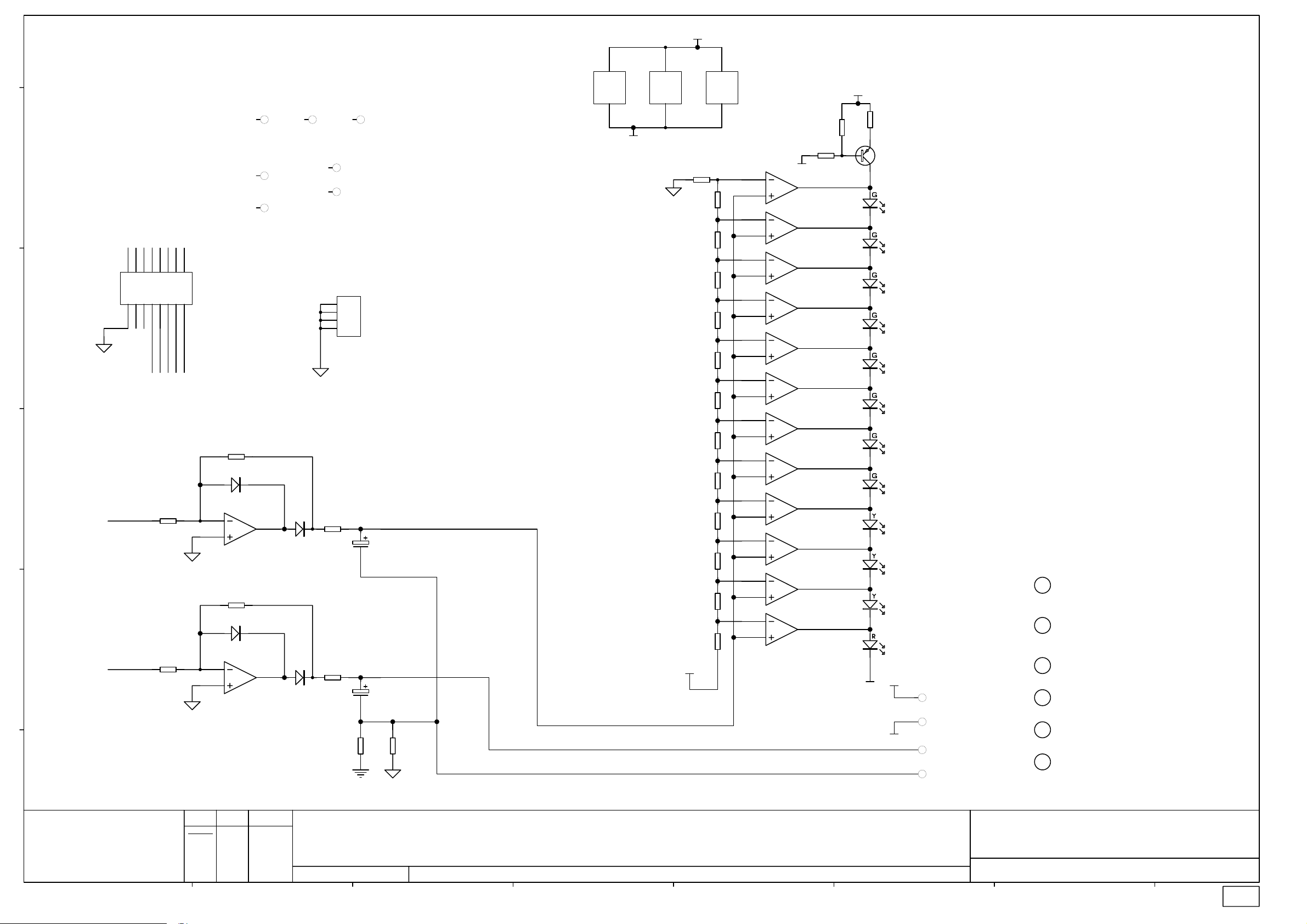
+17VA
003-038/2
3
U7E
LM339 SMD
V+
V-
FID1
FIDUCIAL
e
FB1_OUT
15
13
11
15
13
11
16
14
16
14
d
12
5
7
9
7
9
8812
10
6
10
FB2_OUT TO_MONO_OUT
LEFT_OUT RIGHT_OUT
2TRK_L 2TRK_R
HMF_OUT_BHMF_OUT_A
1
3
CN6
1
3
5
BOX 8X2 M 90 DEG
2
4
6
2
4
LMF_OUT_A LMF_OUT_B
c
U10B
METER_L
R55
56K 1% 0805
b
METER_R
R52
56K 1% 0805
6
5
TL072D SMD
U10A
2
3
TL072D SMD
AI1
HOLE-AI VTECH
AI2
SLOT-AI VTECH
R56
330K 1% 0805
D4
BAS16
7
R53
330K 1% 0805
D2
BAS16
1
FID2
FIDUCIAL
EARTH SCREW TERMINAL NARROW
D5
R57
1K8 0805
BAS16
D3
R54
1K8 0805
BAS16
FID3
FIDUCIAL
FH1
HOLE-FIXING 3.5MM
FH2
HOLE-FIXING 3.5MM
CN7
1
2
3
4
C31
1/63
C30
1/63
R86
NF 0805
R87
0R0 0805
12
-17VA
3
V+
V-
12
U8E
LM339 SMD
R58
120R 1% 0805
R59
120R 1% 0805
R60
120R 1% 0805
R61
120R 1% 0805
R62
120R 1% 0805
R63
330R 1% 0805
R64
330R 1% 0805
R65
560R 1% 0805
R66
680R 1% 0805
R67
1K2 1% 0805
R68
1K2 1% 0805
R69
3K9 0805
R70
1K0 1% 0805
+17VA
3
V+
V-
12
U9E
LM339 SMD
4
5
6
7
8
9
10
11
4
5
6
7
8
9
10
11
4
5
6
7
8
9
10
11
-17VA
U7A
LM339 SMD
U7B
LM339 SMD
U7C
LM339 SMD
U7D
LM339 SMD
U8A
LM339 SMD
U8B
LM339 SMD
U8C
LM339 SMD
U8D
LM339 SMD
U9A
LM339 SMD
U9B
LM339 SMD
U9C
LM339 SMD
U9D
LM339 SMD
R71
15K 0805
2
1
14
13
2
1
14
13
2
1
14
13
+17VA
R73
R72
1K2 1% 0805
4K7 1% 0805
Q2
BC858B
-17VA
LD4
LED BAR
+17VA
-17VA
P4
PIN
P5
PIN
P6
PIN
P7
PIN
PILLAR1
PILLAR M3X11 NYLON TAP
PILLAR2
PILLAR M3X11 NYLON TAP
SCREW1
SCREW M3X6 PAN TORX BK
SCREW2
SCREW M3X6 PAN TORX BK
SCREW3
SCREW M3X6 PAN TORX BK
SCREW4
SCREW M3X6 PAN TORX BK
a
ALLEN&HEATH
Kernick Industrial Estate,
Penryn, Cornwall,
England. TR10 9LU
+44 (0)8707 556250
Tel:
+44 (0)8707 556251
Fax:
ABCDEFGH
ISSUE BY DATE
ORIGIN
A JB 7/3/02
B JB 29/4/02
C AAT 01-05-02
1 AAT 24-07-02
2 MG 21-10-02
FILE: C4792_2P3.Sch 09:59:09 27-Mar-2003
PRINTED:
TITLE:
PA Series Foldback/Phones pcb
PAGE:
DRG No: ISSUE: SHEET: OF
C4792 2 2
2
Page 28

003-038
Page 29

Note: Description includes Allen and Heath part number in brackets
)
)
)
)
)
)
)
)
Designator Description Designator Description
C1 CAPACITOR CERAMIC SMD0805 22P (AF2992) R37 RESISTOR METAL FILM SMD0805 10K 1% (AC2841)
C2 CAPACITOR SMD 1N5 CERAMIC SMD (AF2991
C3 CAPACITOR SMD 1N5 CERAMIC SMD (AF2991
C4 CAPACITOR CERAMIC SMD0805 22P (AF2992) R40 RESISTOR SMD 22K 1% 0805 (AC2842)
C5 CAPACITOR SMD 1N5 CERAMIC SMD (AF2991
C6 CAPACITOR SMD 1N5 CERAMIC SMD (AF2991
C7 CAPACITOR ELECTROLYTIC 100uF 6.3V (AF2984) R43 RESISTOR METAL FILM SMD0805 10K 1% (AC2841)
C8 CAP SM 33pF (AF4887) R44 RESISTOR METAL FILM SMD0805 2K2 1% (AC0370)
C9 CAP SM 33pF (AF4887) R45 RESISTOR METAL FILM SMD0805 2K2 1% (AC0370)
C10 CAPACITOR ELECTROLYTIC 47uF 25V (AF0208) R46 RESISTOR METAL FILM SMD0805 33R 1% (AC2839)
C11 CAPACITOR ELECTROLYTIC 47uF 25V (AF0208) R47 RESISTOR METAL FILM SMD0805 33R 1% (AC2839)
C12 CAPACITOR ELECTROLYTIC 47uF 25V (AF0208) R48 RESISTOR METAL FILM SMD0805 33R 1% (AC2839)
C13 CAPACITOR ELECTROLYTIC 47uF 25V (AF0208) R49 RESISTOR CARBON SMD0805 22K 5% (AC3540)
C14 CAPACITOR ELECTROLYTIC 47uF 25V (AF0208) R50 RESISTOR CARBON SMD0805 22K 5% (AC3540)
C15 CAPACITOR ELECTROLYTIC 47uF 25V (AF0208) R51 RESISTOR METAL FILM SMD0805 33R 1% (AC2839)
C16 CAPACITOR CERAMIC SMD0805 100N (AF2851) R52 RESISTOR SMD 56K 1% 0805 METAL (AC5051)
C17 CAPACITOR CERAMIC SMD0805 100N (AF2851) R53 RESISTOR METAL FILM SMD0805 330K 1% (AC3087)
C18 CAPACITOR CERAMIC SMD0805 100N (AF2851) R54 RESISTOR CARBON SMD0805 1K8 5% (AC3029)
C19 CAPACITOR ELECTROLYTIC 100uF 6.3V (AF2984) R55 RESISTOR SMD 56K 1% 0805 METAL (AC5051)
C20 CAP SM 33pF (AF4887) R56 RESISTOR METAL FILM SMD0805 330K 1% (AC3087)
C21 CAPACITOR ELECTROLYTIC 47uF 25V (AF0208) R57 RESISTOR CARBON SMD0805 1K8 5% (AC3029)
C22 CAPACITOR ELECTROLYTIC 47uF 25V (AF0208) R58 RESISTOR METAL FILM SMD0805 120R 1% (AC3055)
C23 CAPACITOR ELECTROLYTIC 47uF 25V (AF0208) R59 RESISTOR METAL FILM SMD0805 120R 1% (AC3055)
C24 CAP SM 33pF (AF4887) R60 RESISTOR METAL FILM SMD0805 120R 1% (AC3055)
C25 CAPACITOR ELECTROLYTIC 47uF 25V (AF0208) R61 RESISTOR METAL FILM SMD0805 120R 1% (AC3055)
C26 CAP SM 33pF (AF4887) R62 RESISTOR METAL FILM SMD0805 120R 1% (AC3055)
C27 CAPACITOR ELECTROLYTIC 47uF 25V (AF0208) R63 RESISTOR METAL FILM SMD0805 330R 1% (AC3056)
C28 CAPACITOR ELECTROLYTIC 1000uF 6.3V (AF8123) R64 RESISTOR METAL FILM SMD0805 330R 1% (AC3056)
C29 CAPACITOR ELECTROLYTIC 1000uF 6.3V (AF8123) R65 RESISTOR METAL FILM SMD0805 560R 1% (AC3057)
C30 CAPACITOR ELECTROLYTIC 1uF 63V (AF0210) R66 RESISTOR METAL FILM SMD0805 680R 1% (AC3058)
C31 CAPACITOR ELECTROLYTIC 1uF 63V (AF0210) R67 RESISTOR METAL FILM SMD0805 1K2 1% (AC3059)
C32 CAPACITOR ELECTROLYTIC 47uF 25V (AF0208) R68 RESISTOR METAL FILM SMD0805 1K2 1% (AC3059)
C33 CAPACITOR ELECTROLYTIC 47uF 25V (AF0208) R69 RESISTOR CARBON SMD0805 3K9 5% (AC4105)
C34 CAPACITOR ELECTROLYTIC 47uF 25V (AF0208) R70 RESISTOR METAL FILM SMD0805 1K0 1% (AC0369)
CN1 JACK SOCKET HORIZONTAL 6 PIN MET HEADPHONE (AL4713) R71 RESISTOR CARBON SMD0805 15K 5% (AC3486)
CN2 JACK SOCKET HORIZONTAL 6 PIN MET HEADPHONE (AL4713) R72 RESISTOR METAL FILM SMD0805 4K7 1% (AC3062)
CN3 JACK SOCKET HORIZONTAL 6 PIN MET HEADPHONE (AL4713) R73 RESISTOR METAL FILM SMD0805 1K2 1% (AC3059)
CN4 JACK SOCKET HORIZONTAL 6 PIN MET HEADPHONE (AL4713) R74 RESISTOR CARBON SMD0805 47K 5% (AC3035)
CN5 Connector IDC,Molex Type 0.1 Pitch 8x2 pins (AL4335) R75 RESISTOR METAL FILM SMD0805 10K 1% (AC2841)
CN6 Connector IDC,Molex Type 0.1 Pitch 8x2 pins (AL4335) R76 RESISTOR METAL FILM SMD0805 10K 1% (AC2841)
CN7 EARTH SCREW TERMINAL NARROW HORIZONTAL TYPE (AA9000) R77 RESISTOR METAL FILM SMD0805 10K 1% (AC2841)
D1 DIODE SIGNAL SMD BAS16 (AE3352) R78 RESISTOR METAL FILM SMD0805 10K 1% (AC2841)
D2 DIODE SIGNAL SMD BAS16 (AE3352) R79 RESISTOR SMD 2K7 5% 0805 (AC4698)
D3 DIODE SIGNAL SMD BAS16 (AE3352) R80 RESISTOR METAL FILM SMD0805 10K 1% (AC2841)
D4 DIODE SIGNAL SMD BAS16 (AE3352) R81 RESISTOR METAL FILM SMD0805 10K 1% (AC2841)
D5 DIODE SIGNAL SMD BAS16 (AE3352) R82 RESISTOR CARBON SMD0805 15K 5% (AC3486)
LD1 LED 0.2" RED (AE0001) R85 RESISTOR SMD 0R 5% 0805 (AC2838)
LD3 LED T1 3MM RED (AE0086) R87 RESISTOR SMD 0R 5% 0805 (AC2838)
LD2 LED RECT 5x2.5MM TOMBSTONE RED (AE4863
LD4 LED BAR MB12 SQUARE LEDS IN HOUSING 8G,3Y,1R (AE2701) SW2 SWITCH DPDT ALPS (SPUN) LATCHING (AL0162)
Q1 TRANSISTOR NPN BC848B (AE3332) SW3 SWITCH DPDT ALPS (SPUN) LATCHING (AL0162)
Q2 TRANSISTOR PNP BC858B (AE3042) U1 IC SMD 74HC4053 (AE3355)
R1 RESISTOR METAL FILM SMD0805 10K 1% (AC2841) U2 IC SMD DUAL OP-AMP TL072 (AE3335)
R2 RESISTOR METAL FILM SMD0805 10K 1% (AC2841) U3 IC SMD DUAL OP-AMP TL072 (AE3335)
R3 RESISTOR METAL FILM SMD0805 10K 1% (AC2841) U4 IC SMD DUAL OP-AMP NE5532 (AE4699)
R4 RESISTOR METAL FILM SMD0805 10K 1% (AC2841) U5 IC SMD DUAL OP-AMP NE5532 (AE4699)
R5 RESISTOR SMD 2K7 5% 0805 (AC4698) U6 IC SMD DUAL OP-AMP TL072 (AE3335)
R6 RESISTOR METAL FILM SMD0805 10K 1% (AC2841) U7 IC LM339 COMPARATOR SMD (AE4890)
R7 RESISTOR METAL FILM SMD0805 10K 1% (AC2841) U8 IC LM339 COMPARATOR SMD (AE4890)
R8 RESISTOR CARBON SMD0805 15K 5% (AC3486) U9 IC LM339 COMPARATOR SMD (AE4890)
R9 RESISTOR METAL FILM SMD0805 100K 1% (AC2843) U10 IC SMD DUAL OP-AMP TL072 (AE3335)
R10 RESISTOR SMD 27K 1% 0805 METAL (AC5049) U11 IC SMD DUAL OP-AMP TL072 (AE3335)
R11 RESISTOR METAL FILM SMD0805 10K 1% (AC2841) U12 IC SMD DUAL OP-AMP TL072 (AE3335)
R12 RESISTOR METAL FILM SMD0805 10K 1% (AC2841) VR1 POT ALPS 11mm 200KC X2 DUAL GANG 204C (AI8005)
R13 RESISTOR SMD 47K 5% 0805 (AC3035) VR2 POT ALPS 11mm 20KB C/D 203B (AI8004
R14 RESISTOR SMD 47K 5% 0805 (AC3035) VR3 POT ALPS 11mm 200KC X2 DUAL GANG 204C (AI8005)
R15 RESISTOR SMD 15K 1% 0805 METAL (AC5050) VR4 POT ALPS 11mm 20KB C/D 203B (AI8004
R16 RESISTOR CARBON SMD0805 22K 5% (AC3540) VR5 POT ALPS 14mm 20KK x2 203K (AI8007
R17 RESISTOR METAL FILM SMD0805 6K8 1% (AC3064) modification CAP ML CER 100NF 100V 104
R18 RESISTOR CARBON SMD0805 22K 5% (AC3540)
R19 RESISTOR METAL FILM SMD0805 3K3 1% (AC3061)
R20 RESISTOR CARBON SMD0805 68R 5% (AC4101)
R21 RESISTOR CARBON SMD0805 68R 5% (AC4101)
R22 RESISTOR CARBON SMD0805 68R 5% (AC4101)
R23 RESISTOR CARBON SMD0805 68R 5% (AC4101)
R24 RESISTOR CARBON SMD0805 68R 5% (AC4101)
R25 RESISTOR CARBON SMD0805 68R 5% (AC4101)
R26 RESISTOR CARBON 10R PRE FORMED 1/4W 5% (AC5077)
R27 RESISTOR CARBON 10R PRE FORMED 1/4W 5% (AC5077)
R28 RESISTOR METAL FILM SMD0805 4K7 1% (AC3062)
R29 RES SMD 56K 1% 0805 METAL FILM (AC5051)
R30 RESISTOR CARBON SMD0805 220K 5% (AC4108)
R31 RESISTOR CARBON SMD0805 5K6 5% (AC4106)
R32 RESISTOR METAL FILM SMD0805 6K8 1% (AC3064)
R33 RESISTOR CARBON SMD0805 5K6 5% (AC4106)
R34 RESISTOR METAL FILM SMD0805 100K 1% (AC2843)
R35 RESISTOR METAL FILM SMD0805 10K 1% (AC2841)
R36 RESISTOR METAL FILM SMD0805 10K 1% (AC2841)
R38 RESISTOR SMD 22K 1% 0805 (AC2842)
R39 RESISTOR SMD 22K 1% 0805 (AC2842)
R41 RESISTOR SMD 22K 1% 0805 (AC2842)
R42 RESISTOR METAL FILM SMD0805 10K 1% (AC2841)
SW1 SWITCH DPDT ALPS (SPUN) LATCHING (AL0162)
PA-CP FB1 Phones issue 2
Page 1 of 1
003−038
Page 30
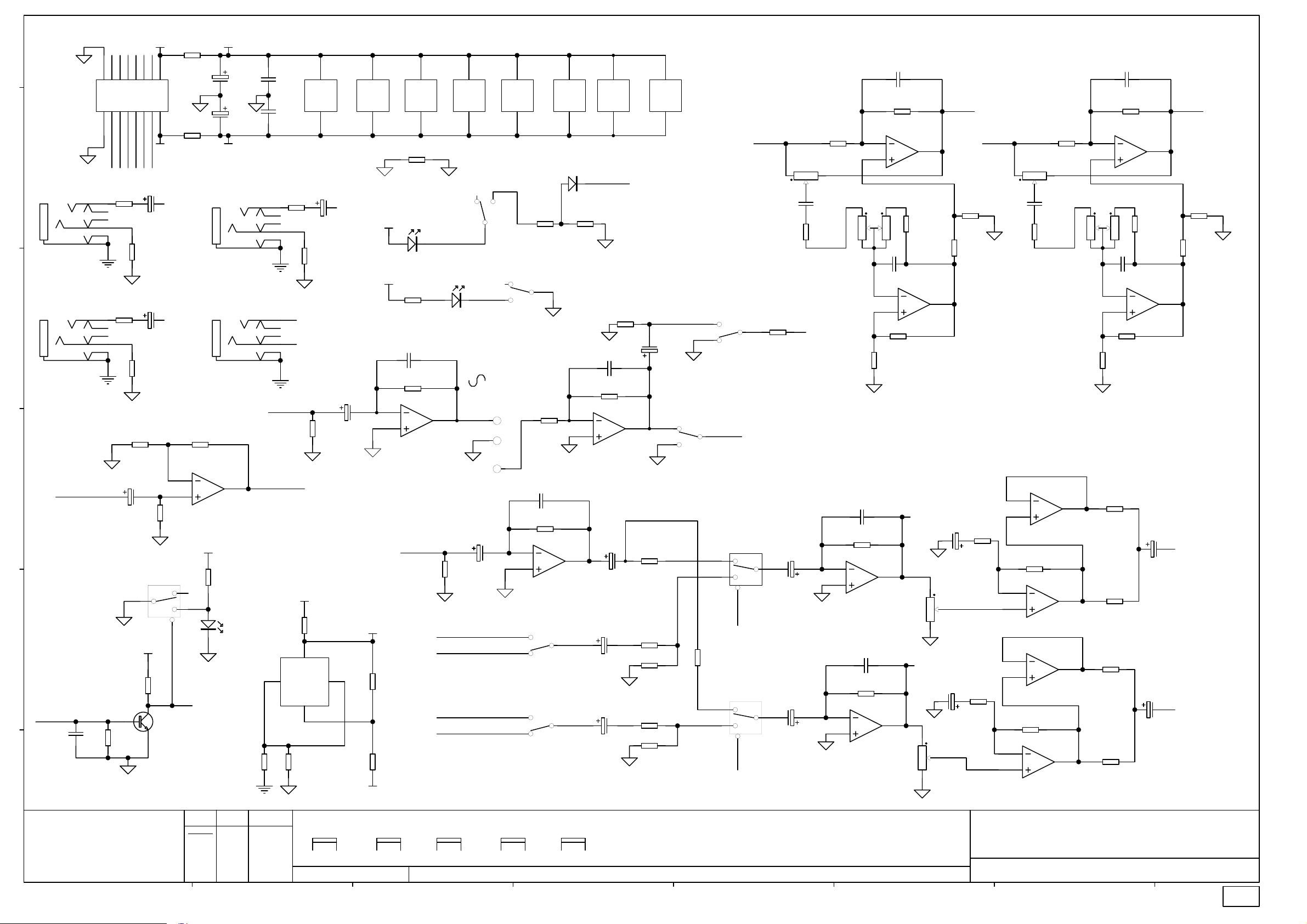
CN5
003-038/1
BOX 8X2 M 90 DEG
e
CN1
R
JACK SLIMJACK MET SW6
CN2
d
c
R
JACK SLIMJACK MET SW6
TO_MONO_OUT
b
PFL_DET
C18
100N_S
1
1
2
2
FB1_OUT
FB2_OUT
R74
47K 0805
C
9
R26
10R PF RAD
R27
10R PF RAD
R12
10K 1% 0805
2
3
+17VA
5
3
PFL_ON_L
+17VA
T
T
74HCT4053
R84
C16
100N_S
C17
100N_S
FB1
MONO_OUT
U1D
8
C14
47/25
C15
47/25
-17VA
CN3
R
JACK SLIMJACK MET SW6
CN4
R
JACK SLIMJACK MET SW6
1
U2A
TL072D SMD
R28
4K7 1% 0805
LD1
LED 5MM RED
NF 0805
R22
68R 0805
PHONES_L
PHONES_R
+17VA
VSS
R85
0R0 0805
8
V+
V-
TL072D SMD
4
C13
47/25
R23
68R 0805
R9
100K 1% 0805
R31
5K6 0805
16
VDD
INH
VEE
7
U3C
U2C
TL072D SMD
MONO_OUT
C7
1000/6.3
6
8
V+
V-
4
GC
+5V
-17VA
U4C
NE5532 SMD
GC
+17VA
+17VA
R17
6K8 1% 0805
C8
CAP SM 33PF
R10
27K 1% 0805
6
5
TL072D SMD
R32
6K8 1% 0805
R33
5K6 0805
U5C
8
V+
V-
4
R83
NF 0805
SW2PCOL (SPUN)
LD3
LED T1 3MM RED
LED RECT 5X2.5MM TOMB RED
U11B
PFL_BUS
8
NE5532 SMD
4
SW3B
LD2
7
R34
100K 1% 0805
2TRK_L
LEFT_OUT
2TRK_R
RIGHT_OUT
V+
V-
4
C19
100/6.3
6
5
4
6
P1
RED
P2
GRN
P3
YEL
8
U6C
V+
V-
TL072D SMD
4
R18
22K 0805
SW2B
SW2PCOL (SPUN)
15K 1% 0805
C20
CAP SM 33PF
6
5
GC
SW2PCOL (SPUN)
3
1
SW2PCOL (SPUN)
6
4
U10C
TL072D SMD
D1
BAS16
5
R15
R35
10K 1% 0805
U2B
TL072D SMD
SW1A
2
SW1B
5
8
V+
V-
4
R19
3K3 1% 0805
CAP SM 33PF
2
3
TL072D SMD
7
PFL_DET
C9
R14
47K 0805
C21
47/25
C22
47/25
C23
47/25
8
U11C
V+
V-
TL072D SMD
4
R13
47K 0805
1
U11A
R36
10K 1% 0805
R38
22K 1% 0805
8
U12C
V+
V-
TL072D SMD
4
C10
47/25
1
3
R39
22K 1% 0805
R40
22K 1% 0805
R41
22K 1% 0805
3
1
SW3A
SW2PCOL (SPUN)
SW2A
SW2PCOL (SPUN)
2
74HCT4053
12
13
R37
10K 1% 0805
74HCT4053
2
1
FB1_OUT
U1A
11
PFL_ON_L
U1B
10
PFL_ON_L
LMF_OUT_A
1N5_S
R16
2
22K 0805
A
14
B
15
10K 1% 0805
VR2A
POT11 20KB C/D
2
C2
R3
10K 1% 0805
PFL_BUS
C33
47/25
C34
47/25
R1
2
3
13
VR1A
POT11 200KC X2 D/G
2
1
C26
CAP SM 33PF
R43
10K 1% 0805
6
5
U3B
TL072D SMD
C24
CAP SM 33PF
R42
10K 1% 0805
2
3
U3A
TL072D SMD
POT14 20KK X2
C1
22P_S
R2
10K 1% 0805
U6A
TL072D SMD
3
R4
10K 1% 0805
C3
1N5_S
6
5
U6B
TL072D SMD
R7
10K 1% 0805
R8
15K 0805
METER_L
7
VR5A
POT14 20KK X2
METER_R
1
VR5B
C4
22P_S
HMF_OUT_A
R75
2
3
VR3A
2
1
R82
15K 0805
R46
33R 1% 0805
R47
33R 1% 0805
R48
33R 1% 0805
R51
33R 1% 0805
10K 1% 0805
TL072D SMD
3
C6
1N5_S
6
5
R81
10K 1% 0805
1
U12A
R78
10K 1% 0805
U12B
TL072D SMD
C29
1000/6.3
C28
1000/6.3
R76
10K 1% 0805
VR4A
POT11 20KB C/D
2
C5
1N5_S
R77
10K 1% 0805
6
5
U4B
NE5532 SMD
R49
22K 0805
NE5532 SMD
U5B
NE5532 SMD
R50
22K 0805
U5A
NE5532 SMD
13
POT11 200KC X2 D/G
7
1
U4A
7
1
R5
2K7 0805
R6
10K 1% 0805
R44
2K2 1% 0805
4
R45
2K2 1% 0805
LMF_OUT_B
2
3
6
5
2
3
1
7
C25
47/25
1 6
C27
47/25
3
2 5
R79
2K7 0805
R80
10K 1% 0805
7
PHONES_L
PHONES_R
HMF_OUT_B
GC
3
5
7
9
5
7
9
6
8812
10
4
6
10
+48V
FB1 FB2
AUX1 FX
MIXL MIXR
C11
47/25
R21
68R 0805
C12
47/25
R25
68R 0805
R11
10K 1% 0805
C32
47/25
74HCT4053
4
+5V
R29
V+
3
4
V-
U1C
Q1
BC848B
PFL_DET
15
13
11
15
13
11
16
14
16
14
12
PFL_BUS
R20
68R 0805
T
R24
68R 0805
T
27K 0805
R30
220K 0805
a
ALLEN&HEATH
Kernick Industrial Estate,
Penryn, Cornwall,
England. TR10 9LU
+44 (0)8707 556250
Tel:
+44 (0)8707 556251
Fax:
ABCDEFGH
ISSUE BY DATE
ORIGIN
A JB 7/3/02
B JB 29/4/02
C AAT 01-05-02
1 AAT 24-07-02
2 MG 21-10-02
2.1 MG 07-07-03
VR1B
POT11 200KC X2 D/G
BRKT
5
6
FILE: C4792_2.1P1.Sch 16:04:25 29-Jul-2003
VR2B
POT11 20KB C/D
BRKT
5
6
VR3B
POT11 200KC X2 D/G
BRKT
5
PRINTED:
6
VR4B
POT11 20KB C/D
BRKT
5
6
VR5C
POT14 20KK X2
BRKT
8
9
TITLE:
PA Series Foldback/Phones pcb
PAGE:
DRG No: ISSUE: SHEET: OF
C4792 1 2
2.1
Page 31

+17VA
003-038/2
3
U7E
LM339 SMD
V+
V-
FID1
FIDUCIAL
e
FB1_OUT
15
13
11
15
13
11
16
14
16
14
d
12
5
7
9
7
9
8812
10
6
10
FB2_OUT TO_MONO_OUT
LEFT_OUT RIGHT_OUT
2TRK_L 2TRK_R
HMF_OUT_BHMF_OUT_A
1
3
CN6
1
3
5
BOX 8X2 M 90 DEG
2
4
6
2
4
LMF_OUT_A LMF_OUT_B
c
U10B
METER_L
R55
56K 1% 0805
b
METER_R
R52
56K 1% 0805
6
5
TL072D SMD
U10A
2
3
TL072D SMD
AI1
HOLE-AI VTECH
AI2
SLOT-AI VTECH
R56
330K 1% 0805
D4
BAS16
7
R53
330K 1% 0805
D2
BAS16
1
FID2
FIDUCIAL
EARTH SCREW TERMINAL NARROW
D5
R57
1K8 0805
BAS16
D3
R54
1K8 0805
BAS16
FID3
FIDUCIAL
FH1
HOLE-FIXING 3.5MM
FH2
HOLE-FIXING 3.5MM
CN7
1
2
3
4
C31
1/63
C30
1/63
R86
NF 0805
R87
0R0 0805
12
-17VA
3
V+
V-
12
U8E
LM339 SMD
R58
120R 1% 0805
R59
120R 1% 0805
R60
120R 1% 0805
R61
120R 1% 0805
R62
120R 1% 0805
R63
330R 1% 0805
R64
330R 1% 0805
R65
560R 1% 0805
R66
680R 1% 0805
R67
1K2 1% 0805
R68
1K2 1% 0805
R69
3K9 0805
R70
1K0 1% 0805
+17VA
3
V+
V-
12
U9E
LM339 SMD
4
5
6
7
8
9
10
11
4
5
6
7
8
9
10
11
4
5
6
7
8
9
10
11
1K 1% 0805
-17VA
U7A
LM339 SMD
U7B
LM339 SMD
U7C
LM339 SMD
U7D
LM339 SMD
U8A
LM339 SMD
U8B
LM339 SMD
U8C
LM339 SMD
U8D
LM339 SMD
U9A
LM339 SMD
U9B
LM339 SMD
U9C
LM339 SMD
U9D
LM339 SMD
R72
R71
15K 0805
2
1
14
13
2
1
14
13
2
1
14
13
+17VA
-17VA
R73
180R 0805
Q2
BC858B
LD4
LED BAR
+17VA
-17VA
P4
PIN
P5
PIN
P6
PIN
P7
PIN
PILLAR1
PILLAR M3X11 NYLON TAP
PILLAR2
PILLAR M3X11 NYLON TAP
SCREW1
SCREW M3X6 PAN TORX BK
SCREW2
SCREW M3X6 PAN TORX BK
SCREW3
SCREW M3X6 PAN TORX BK
SCREW4
SCREW M3X6 PAN TORX BK
a
ALLEN&HEATH
Kernick Industrial Estate,
Penryn, Cornwall,
England. TR10 9LU
+44 (0)8707 556250
Tel:
+44 (0)8707 556251
Fax:
ABCDEFGH
ISSUE BY DATE
ORIGIN
A JB 7/3/02
B JB 29/4/02
C AAT 01-05-02
1 AAT 24-07-02
2 MG 21-10-02
2.1 MG 07-07-03
FILE: C4792_2.1P2.Sch 16:04:25 29-Jul-2003
PRINTED:
TITLE:
PA Series Foldback/Phones pcb
PAGE:
DRG No: ISSUE: SHEET: OF
C4792 2 2
2.1
Page 32

003-038
Page 33

R1
003-039/1
C1
CN1
JACK SLIMJACK MET SW6
CN2
e
JACK SLIMJACK MET SW6
CN3
JACK SLIMJACK MET SW6
d
CN4
T
R
T
R
T
R
T
R
68R 0805
R3
68R 0805
R2
68R 0805
R4
68R 0805
47/25
C2
47/25
INSEND_R
INSRET_R
INSEND_L
INSRET_L
RIGHT_OUT
LEFT_OUT
2
3
VR3A
2
1
C11
22P_S
R13
10K 1% 0805
U2A
TL072D SMD
3
C9
470P 0805
U2B
6
5
R25
6K8 1% 0805
R23
10K 1% 0805
1
R8
15K 0805
TL072D SMD
R14
10K 1% 0805
7
HF_OUT_BHF_OUT_A
R19
2K7 0805
C10
22P_S
R10
10K 1% 0805
2
C6
470P 0805
R5
15K 0805
R9
10K 1% 0805
13
HMF_OUT_A HMF_OUT_B
VR2A
POT11 20KB C/D
FB2_OUT
HF_OUT_A
RIGHT_OUTLEFT_OUT
15
13
11
15
13
11
16
14
16
14
12
1
3
5
7
9
CN5
1
3
5
7
9
10
10
HMF_OUT_B HF_OUT_B
HMF_OUT_A
4
6
8812
4
6
INSEND_L INSRET_L
INSEND_R INSRET_R
BOX 8X2 M 90 DEG
2
2
2
3
TL072D SMD
VR1A
POT11 200KC X2 D/G
2
1
3
C7
470P 0805
6
5
TL072D SMD
R24
6K8 1% 0805
R22
10K 1% 0805
U1A
R6
15K 0805
U1B
1
7
R18
2K7 0805
R11
10K 1% 0805
VR4A
POT11 20KB C/D
CN7
EARTH SCREW TERMINAL NARROW
2
C8
470P 0805
R7
15K 0805
R12
10K 1% 0805
13
POT11 200KC X2 D/G
JACK SLIMJACK MET SW6
R20
47K 0805
C12
33P 0805
R15
c
FB2
C14
R26
100/6.3
100K 1% 0805
GC
6
5
27K 0805
U3B
TL072D SMD
P1
7
RED
P2
GRN
P3
YEL
R16
15K 0805
+17VA
C13
33P 0805
R17
47K 0805
2
3
U3A
TL072D SMD
LD1
R27
6K8 1% 0805
LED RECT 5X2.5MM TOMB RED
C3
47/25
1
1
3
4
6
b
+17VA
3
SW2A
1
SW2PCOL (SPUN)
SW1A
SW2PCOL (SPUN)
2
SW1B
SW2PCOL (SPUN)
5
PFL_DET
4
SW2B
SW2PCOL (SPUN)
5
6
D1
BAS16
R28
22K 0805
2
R21
22K 0805
R29
3K3 1% 0805
PFL_BUS
FB2_OUT
AI1
HOLE-AI
AI2
SLOT-AI VTECH
AI3
SLOT-AI VTECH
BOX 8X2 M 90 DEG
CN6
FID1
FIDUCIAL
FID3
FIDUCIAL
R32
NF 0805
15
13
15
13
16
14
16
14
PFL_DET
11
12
PFL_BUS
9
11
10
MIXL MIXR
5
7
7
9
8812
10
6
FB1 FB2
AUX1 FX
123
4
SGND
FID2
FIDUCIAL
FB1
EARTH SCREW TERMINAL NARROW
123
4
GC
1
1
2
2
R30
10R PF RAD
R31
10R PF RAD
+17VA
47/25
47/25
-17VA
C4
C5
3
5
6
4
+48V
V+
3
4
V-
C15
100N 0805
C16
100N 0805
U1C
8
TL072D SMD
V+
V-
4
U2C
8
TL072D SMD
V+
V-
4
U3C
8
TL072D SMD
V+
V-
4
a
ALLEN&HEATH
Kernick Industrial Estate,
Penryn, Cornwall,
England. TR10 9LU
+44 (0)8707 556250
Tel:
+44 (0)8707 556251
Fax:
ABCDEFGH
ISSUE BY DATE
ORIGIN
A JB 7/3/02
B AAT 19-04-02
1 AAT 27-06-02
LD2
LED T1 3MM RED
VR1B
POT11 200KC X2 D/G
BRKT
5
6
FILE: C4793 _1.Sch 10:31:27 27-Mar-2003
VR2B
POT11 20KB C/D
BRKT
5
6
PRINTED:
VR3B
POT11 200KC X2 D/G
BRKT
5
6
VR4B
POT11 20KB C/D
BRKT
5
6
PAGE:
DRG No: ISSUE: SHEET: OF
TITLE:
PA SERIES FB2 PCB
C4793 1 1
1
Page 34

003-039
Page 35

Note: Description includes Allen and Heath part number in brackets
)
)
)
)
Designator Description
C1 CAPACITOR ELECTROLYTIC 47uF 25V (AF0208)
C2 CAPACITOR ELECTROLYTIC 47uF 25V (AF0208)
C3 CAPACITOR ELECTROLYTIC 47uF 25V (AF0208)
C4 CAPACITOR ELECTROLYTIC 47uF 25V (AF0208)
C5 CAPACITOR ELECTROLYTIC 47uF 25V (AF0208)
C6 CAPACITOR SMD 470P CERAMIC 0805 (AF2848)
C7 CAPACITOR SMD 470P CERAMIC 0805 (AF2848)
C8 CAPACITOR SMD 470P CERAMIC 0805 (AF2848)
C9 CAPACITOR SMD 470P CERAMIC 0805 (AF2848)
C10 CAPACITOR CERAMIC SMD0805 22P (AF2992)
C11 CAPACITOR CERAMIC SMD0805 22P (AF2992)
C12 CAPACITOR CERAMIC SMD0805 33P (AF4887)
C13 CAPACITOR CERAMIC SMD0805 33P (AF4887)
C14 CAPACITOR ELECTROLYTIC 100uF 6.3V (AF2984)
C15 CAPACITOR CERAMIC SMD0805 100N (AF2851)
C16 CAPACITOR CERAMIC SMD0805 100N (AF2851)
CN1 JACK SOCKET HORIZONTAL 6 PIN MET HEADPHONE (AL4713)
CN2 JACK SOCKET HORIZONTAL 6 PIN MET HEADPHONE (AL4713)
CN3 JACK SOCKET HORIZONTAL 6 PIN MET HEADPHONE (AL4713)
CN4 JACK SOCKET HORIZONTAL 6 PIN MET HEADPHONE (AL4713)
CN5 Connector IDC,Molex Type 0.1 Pitch 8x2 pins (AL4335)
CN6 Connector IDC,Molex Type 0.1 Pitch 8x2 pins (AL4335)
CN7 EARTH SCREW TERMINAL NARROW HORIZONTAL TYPE (AA9000)
D1 DIODE SIGNAL SMD BAS16 (AE3352)
LD1 LED RECT 5x2.5MM TOMBSTONE RED (AE4863
LD2 LED T1 3mm RED (AE0086
R1 RESISTOR CARBON SMD0805 68R 5% (AC4101)
R2 RESISTOR CARBON SMD0805 68R 5% (AC4101)
R3 RESISTOR CARBON SMD0805 68R 5% (AC4101)
R4 RESISTOR CARBON SMD0805 68R 5% (AC4101)
R5 RESISTOR CARBON SMD0805 15K 5% (AC3486)
R6 RESISTOR CARBON SMD0805 15K 5% (AC3486)
R7 RESISTOR CARBON SMD0805 15K 5% (AC3486)
R8 RESISTOR CARBON SMD0805 15K 5% (AC3486)
R9 RESISTOR METAL FILM SMD0805 10K 1% (AC2841)
R10 RESISTOR METAL FILM SMD0805 10K 1% (AC2841)
R11 RESISTOR METAL FILM SMD0805 10K 1% (AC2841)
R12 RESISTOR METAL FILM SMD0805 10K 1% (AC2841)
R13 RESISTOR METAL FILM SMD0805 10K 1% (AC2841)
R14 RESISTOR METAL FILM SMD0805 10K 1% (AC2841)
R15 RESISTOR CARBON SMD0805 27K 5% (AC4693)
R16 RESISTOR CARBON SMD0805 15K 5% (AC3486)
R17 RESISTOR CARBON SMD0805 47K 5% (AC3035)
R18 RESISTOR CARBON SMD0805 2K7 5% (AC4698)
R19 RESISTOR CARBON SMD0805 2K7 5% (AC4698)
R20 RESISTOR CARBON SMD0805 47K 5% (AC3035)
R21 RESISTOR CARBON SMD0805 22K 5% (AC3540)
R22 RESISTOR METAL FILM SMD0805 10K 1% (AC2841)
R23 RESISTOR METAL FILM SMD0805 10K 1% (AC2841)
R24 RESISTOR METAL FILM SMD0805 6K8 1% (AC3064)
R25 RESISTOR METAL FILM SMD0805 6K8 1% (AC3064)
R26 RESISTOR METAL FILM SMD0805 100K 1% (AC2843)
R27 RESISTOR METAL FILM SMD0805 6K8 1% (AC3064)
R28 RESISTOR CARBON SMD0805 22K 5% (AC3540)
R29 RESISTOR METAL FILM SMD0805 3K3 1% (AC3061)
R30 RESISTOR CARBON 10R PRE FORMED 1/4W 5% (AC0378)
R31 RESISTOR CARBON 10R PRE FORMED 1/4W 5% (AC0378)
SW1 SWITCH DPDT ALPS (SPUN) LATCHING (AL0162)
SW2 SWITCH DPDT ALPS (SPUN) LATCHING (AL0162)
U1 IC SMD DUAL OP-AMP TL072 (AE3335)
U2 IC SMD DUAL OP-AMP TL072 (AE3335)
U3 IC SMD DUAL OP-AMP TL072 (AE3335)
VR1 POT ALPS 11mm 200KC X2 DUAL GANG 204C (AI8005)
VR2 POT ALPS 11mm 20KB C/D 203B (AI8004
VR3 POT ALPS 11mm 200KC X2 DUAL GANG 204C (AI8005)
VR4 POT ALPS 11mm 20KB C/D 203B (AI8004
PA-CP FB2 issue 1
Page 1 of 1
003−039
Page 36

R1
003-039/1
C1
CN1
JACK SLIMJACK MET SW6
CN2
e
JACK SLIMJACK MET SW6
CN3
JACK SLIMJACK MET SW6
d
CN4
T
R
T
R
T
R
T
R
68R 0805
R3
68R 0805
R2
68R 0805
R4
68R 0805
47/25
C2
47/25
INSEND_R
INSRET_R
INSEND_L
INSRET_L
RIGHT_OUT
LEFT_OUT
2
3
VR3A
2
1
C11
22P_S
R13
10K 1% 0805
U2A
TL072D SMD
3
C9
470P 0805
U2B
6
5
R25
6K8 1% 0805
R23
10K 1% 0805
1
R8
15K 0805
TL072D SMD
R14
10K 1% 0805
7
HF_OUT_BHF_OUT_A
R19
2K7 0805
C10
22P_S
R10
10K 1% 0805
2
C6
470P 0805
R5
15K 0805
R9
10K 1% 0805
13
HMF_OUT_A HMF_OUT_B
VR2A
POT11 20KB C/D
FB2_OUT
HF_OUT_A
RIGHT_OUTLEFT_OUT
15
13
11
15
13
11
16
14
16
14
12
1
3
5
7
9
CN5
1
3
5
7
9
10
10
HMF_OUT_B HF_OUT_B
HMF_OUT_A
4
6
8812
4
6
INSEND_L INSRET_L
INSEND_R INSRET_R
BOX 8X2 M 90 DEG
2
2
2
3
TL072D SMD
VR1A
POT11 200KC X2 D/G
2
1
3
C7
470P 0805
6
5
TL072D SMD
R24
6K8 1% 0805
R22
10K 1% 0805
U1A
R6
15K 0805
U1B
1
7
R18
2K7 0805
R11
10K 1% 0805
VR4A
POT11 20KB C/D
CN7
EARTH SCREW TERMINAL NARROW
2
C8
470P 0805
R7
15K 0805
R12
10K 1% 0805
13
POT11 200KC X2 D/G
JACK SLIMJACK MET SW6
R20
47K 0805
C12
33P 0805
6
5
R15
27K 0805
U3B
TL072D SMD
P1
7
RED
P2
GRN
P3
YEL
R16
15K 0805
+17VA
C14
c
FB2
1000/6.3
R26
100K 1% 0805
GC
C13
33P 0805
R17
47K 0805
2
3
U3A
TL072D SMD
LD1
R27
6K8 1% 0805
LED RECT 5X2.5MM TOMB RED
C3
47/25
1
1
3
4
6
b
+17VA
3
SW2A
1
SW2PCOL (SPUN)
SW1A
SW2PCOL (SPUN)
2
SW1B
SW2PCOL (SPUN)
5
PFL_DET
4
SW2B
SW2PCOL (SPUN)
5
6
D1
BAS16
R28
22K 0805
2
R21
22K 0805
R29
3K3 1% 0805
PFL_BUS
FB2_OUT
AI1
HOLE-AI
AI2
SLOT-AI VTECH
AI3
SLOT-AI VTECH
BOX 8X2 M 90 DEG
CN6
FID1
FIDUCIAL
FID3
FIDUCIAL
R32
NF 0805
15
13
15
13
16
14
16
14
PFL_DET
11
12
PFL_BUS
9
11
10
MIXL MIXR
5
7
7
9
8812
10
6
FB1 FB2
AUX1 FX
123
4
SGND
FID2
FIDUCIAL
FB1
EARTH SCREW TERMINAL NARROW
123
4
GC
1
1
2
2
R30
10R PF RAD
R31
10R PF RAD
+17VA
47/25
47/25
-17VA
C4
C5
3
5
6
4
+48V
V+
3
4
V-
C15
100N 0805
C16
100N 0805
U1C
8
TL072D SMD
V+
V-
4
U2C
8
TL072D SMD
V+
V-
4
U3C
8
TL072D SMD
V+
V-
4
a
ALLEN&HEATH
Kernick Industrial Estate,
Penryn, Cornwall,
England. TR10 9LU
+44 (0)8707 556250
Tel:
+44 (0)8707 556251
Fax:
ABCDEFGH
ISSUE BY DATE
ORIGIN
A JB 7/3/02
B AAT 19-04-02
1 AAT 27-06-02
1.1 MG 7-7-03
LD2
LED T1 3MM RED
VR1B
POT11 200KC X2 D/G
BRKT
5
6
FILE: C4793 _1.1.Sch 16:16:38 29-Jul-2003
VR2B
POT11 20KB C/D
BRKT
5
6
PRINTED:
VR3B
POT11 200KC X2 D/G
BRKT
5
6
POT11 20KB C/D
BRKT
5
VR4B
6
PAGE:
DRG No: ISSUE: SHEET: OF
TITLE:
PA SERIES FB2 PCB
C4793 1 1
1.1
Page 37

003-039
 Loading...