

Page 1

Dual Function Live Sound Console
SERVICE MANUAL
Publication AP4316
Page 2

Introduction
This service manual provides technical information on the Allen & Heath ML4000 audio console.
Included is the technical specification, system block diagram, circuit schematics with board layouts,
and a spare parts list. Information on the power supply is available in a separate publication. Only
technically qualified service personnel should carry out service work on the console and its power
supply.
Whilst we believe the information in this manual to be reliable we do not assume responsibility for
inaccuracies. We also reserve the right to make changes in the interest of further product
development.
We are able to offer further product support through our world-wide network of approved dealers
and service agents. You can also access our Web site on the Internet for information on our
product range and further technical support. To help us provide the most efficient service please
keep a record of the console serial number, and date and place of purchase to be quoted in any
communication regarding this product. The serial number is located on the rear panel.
Check out our home site for information on the company and its pedigree, our full product range
and our design philosophy. We also have a site dedicated to the ML Series consoles.
www.mlseries.com
www.allen-heath.com
ML4000 Service Manual AP4316 Issue 3
Copyright © 2002 Allen & Heath. All rights reserved
This product complies with the European Electromagnetic
Compatibility directives 89/336/EEC & 92/31/EEC and the
European Low Voltage Directives 73/23/EEC & 93/68/EEC.
This product has been tested to EN55103 Parts 1 & 2 1996 for use in
Environments E1, E2, E3, and E4 to demonstrate compliance with the
protection requirements in the European EMC directive 89/336/EEC. During
some tests the specified performance figures of the product were affected.
This is considered permissible and the product has been passed as
acceptable for its intended use.
Allen & Heath has a strict policy of ensuring all products are tested to the
latest safety and EMC standards. Customers requiring more information
about EMC and safety issues can contact Allen & Heath.
NOTE: Any changes or modifications to the console not approved by Allen &
Heath could void the compliance of the console and therefore the users
authority to operate it.
Manufactured in the United Kingdom by Allen & Heath
Kernick Industrial Estate, Penryn, Cornwall, TR10 9LU, UK
http://www.allen-heath.com
2 ML4000 Service Manual
Page 3

Contents
Important Safety Instructions .............................. 4
Mains Plug Wiring Instructions............................ 5
General Precautions ............................................ 5
ML4000 Key Features ......................................... 6
Front Panel Layout .............................................. 7
Rear Panel Layouts.............................................. 8
Technical Specifications...................................... 9
System Block Diagram ...................................... 10
Installation Details.............................................. 12
Earthing.............................................................. 13
Audio Connector Types and Wiring .................. 14
Gain Structure.................................................... 15
MIDI.................................................................... 16
BLOCK DIAGRAM............................................. M1
INTERNAL ASSEMBLY MAP ...................... M2-M3
MONO INPUT .............................................. D1-D4
STEREO INPUT ...........................................D5-D8
MASTER CONNECTOR............................. D9-D10
GROUP 1,3,5,7 ........................................ D11-D13
GROUP 2,4,6,8 ........................................ D14-D17
AUX 9 ....................................................... D18-D21
AUX 10 ..................................................... D22-D25
AUX 11 ..................................................... D26-D29
AUX 12 ..................................................... D30-D33
MASTER DISTRIBUTION................................. D34
LRC VU METERS..................................... D35-D36
Console Computer and Operating Software .... 19
Internal Option Links ......................................... 20
Internal assembly assignments......................... 20
The Range ......................................................... 21
Ordering Spares ................................................ 21
Technical Drawings ........................................... 22
LRC LED METERS........................................... D37
1-12 VU METERS..................................... D38-D40
SYSLINK INPUT...............................................D41
MIDI/PSU ................................................. D42-D43
DC POWER WIRING........................................ D44
CPU.......................................................... D45-D48
GRAUX SLAVE......................................... D49-D50
VCA MASTER SLAVE ......................................D51
LRC SLAVE .............................................. D52-D53
MASTER FADER.............................................. D54
MUTE GROUP .................................................D55
MONO FADER SLAVE............................. D56-D57
MONO FADER ................................................. D58
FADER BISCUIT (misc) ...................................D59
SYSLINK OUTPUT................................... D60-D61
ML4000 Service Manual 3
Page 4
quip
Important Safety Instructions
WARNINGS - Read the following before proceeding :
CAUTION
ATTENTION: RISQUE DE CHOC ELECTRIQUE – NE PAS OUVRIR
Read instructions: Retain these safety and operating instructions for future reference. Adhere to
all warnings printed here and on the console power unit. Follow the operating
instructions printed in this user guide and the power unit user guide.
Do not remove covers: Operate the power unit with its covers correctly fitted. Refer any service work
to competent technical personnel only.
Power sources: Connect the power unit to a mains power only of the type described in this
User Guide and marked on the rear panel. Use the power cord with sealed
mains plug appropriate for your local mains supply as provided with the
console. If the provided plug does not fit into your outlet consult your service
agent for assistance.
Power cord routing: Route the power cord so that it is not likely to be walked on, stretched or
pinched by items placed upon or against it.
Grounding: Do not defeat the grounding and polarisation means of the power cord plug.
Do not remove or tamper with the ground connection in the power cord.
WARNING: This e
ment must be earthed.
Water and moisture: To reduce the risk of fire or electric shock do not expose the power unit or
console to rain or moisture or use it in damp or wet conditions. Do not place
containers of liquids on it which might spill into any openings.
Ventilation: Do not obstruct the ventilation slots or position the console or power unit
where the air flow required for ventilation is impeded. If the console is to be
operated in a flightcase ensure that it is constructed to allow adequate
ventilation.
Heat and vibration: Do not locate the power unit in a place subject to excessive heat or direct
sunlight as this could be a fire hazard. Locate the console and its power unit
away from any equipment which produces heat or causes excessive
vibration.
Servicing: Switch off the equipment and unplug the power cord immediately if it is
exposed to moisture, spilled liquid, objects fallen into the openings, the power
cord or plug become damaged, during lightening storms, or if smoke, odour
or noise is noticed. Refer servicing to qualified technical personnel only.
Installation: Install the console in accordance with the instructions printed in this User
Guide. Do not connect the output of power amplifiers directly to the console.
Use audio connectors and plugs only for their intended purpose.
4 ML4000 Service Manual
Page 5
Important Mains Plug Wiring Instructions.
The power unit is supplied with a moulded mains plug fitted to the AC mains
power lead. Follow the instructions below if the mains plug has to be
replaced.
The mains lead wires are coloured in accordance with the following code:
TERMINAL
L
LIVE BROWN BLACK
N
NEUTRAL BLUE WHITE
E
EARTH GND GREEN & YELLOW GREEN
The wire which is coloured Green and Yellow must be connected to the
terminal in the plug which is marked with the letter E or with the Earth symbol.
This appliance must be earthed.
The wire which is coloured Blue must be connected to the terminal in the plug
which is marked with the letter N.
The wire which is coloured Brown must be connected to the terminal in the
plug which is marked with the letter L.
Ensure that these colour codes are followed carefully in the event of the plug
being changed.
General Precautions
WIRE COLOUR
European USA/Canada
Damage : To prevent damage to the controls and cosmetics avoid placing heavy
objects on the control surface, scratching the surface with sharp objects, or
subjecting the console to rough handling and vibration.
Environment : Protect from excessive dirt, dust, heat and vibration when operating and
storing. Avoid tobacco ash, smoke, drinks spillage, and exposure to rain and
moisture. If the console becomes wet, switch off and remove mains power
immediately. Allow to dry out thoroughly before using again.
Radiation : To avoid induced noise and interference pickup do not operate the console
close to strong sources of electromagnetic radiation such as power supplies,
video monitors, lighting cables and dimmers.
Cleaning : Avoid the use of chemicals, abrasives or solvents. The control panel is best
cleaned with a soft brush and dry lint-free cloth. Stubborn marks can be
removed using a cloth dampened with isopropyl alcohol. Do not leave
marking tape stuck to the console for long periods of time as the adhesive
can degrade and leave a sticky residue. The faders, switches and
potentiometers are lubricated for life. The use of electrical lubricants on these
parts is not recommended. Refer to the power unit user guide for instructions
on cleaning its ventilation filters.
Transporting : The console should be transported in the original packing or purpose built
foam lined flightcase. Protect the control surface from damage during transit.
The console is a large and heavy item. To avoid injury ensure adequate man
power and precaution when lifting or moving the console.
ML4000 Service Manual 5
Page 6

ML4000 Key Features
The Allen & Heath ML4000 is a large format VCA equipped dual function live sound console
providing many of the features of its larger brother the ML5000. It can be quickly configured for
front-of-house (FOH) or stage monitor mixing. As one console suitable for both applications it is
equally well suited to installation, rental and touring. It offers an IO capability and feature set that
satisfies the latest trends in live sound engineering, in particular the growing number of inputs and
outputs for multi-speaker house and monitor systems, demands of stereo in-ear monitoring, 3
speaker LCR imaging, advanced grouping and automation. The design ensures on-the-road
durability, a clear layout for easy walk up and go operation, and no-compromise audio
performance.
Inputs and Outputs
3 Standard frame sizes: 32+2, 40+2, 48+2 (mono + dual stereo channels)
32, 40, 48 mono mic/line inputs with inserts and direct outputs
2 dual stereo line inputs
24 input sidecar to expand to a maximum 96 inputs
Main Left, Right and Centre outputs with inserts, Centre configurable as the engineers monitor
8 Groups, 12 Auxes: Group/Aux 1-8 and Aux 9-12 with faders and inserts, Aux 1-8 with rotaries
11x4 Matrix
2-Track monitor input and recording send
Stereo headphones and local monitors
Talkback mic input
ClearCom compatible intercom interface
Groups and Automation
8 VCA groups with mutes and PAFL monitoring
8 audio groups with LCRplus™ sub grouping
8 mute groups
MIDI accessible snapshot memories
MIDI mute on/off, snapshot recall and dump in/out control
Channels can be made safe from the automation
Processing and Control
4-Band full sweep mono EQ with switched Q mids, 4-band fixed frequency stereo EQ
Sweepable high pass filter
LCRplus™ 3 speaker imaging system
Protected mode switching to configure the console for FOH or monitor application
Intelligent PAFL system with all-clear, PFL/in-place AFL, priority, auto-cancel/add mode…
Assignable talkback and intercom
1kHz tone and pink noise generator for system line-up and testing
Full console monitoring and extensive metering of inputs, mix busses and outputs
6 ML4000 Service Manual
Page 7
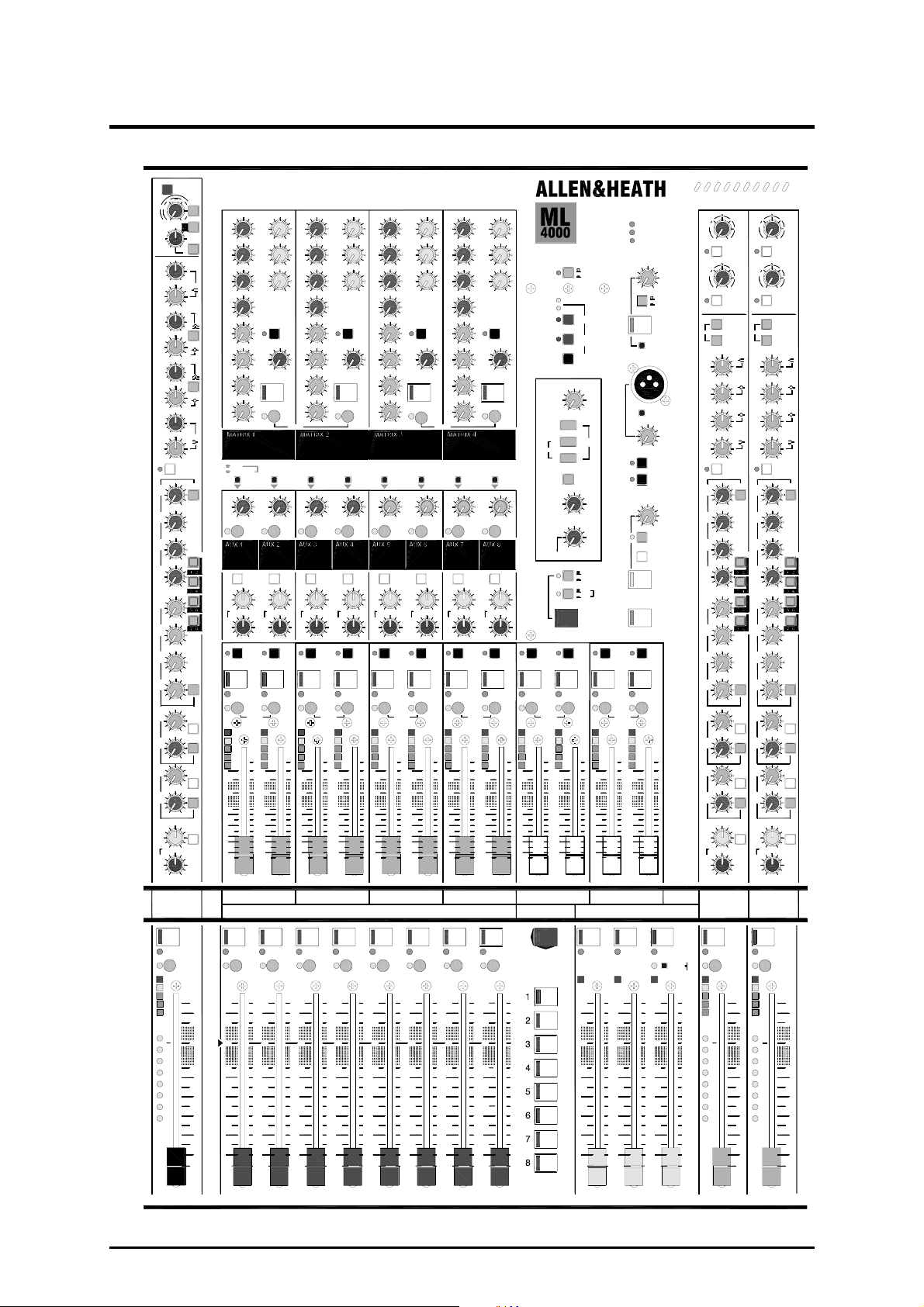
Front Panel Layout
+48V
PAD
40
20dB
GAIN
602010- 10
40
1
L
mode
LEV
AUX
LCR
BLEND
PAN
10
0
5
10
20
30
40
R
C3
MUTE
2
+
LRC
MUTE
5
0
5
10
20
30
OO
VCA 2
SAFE
5
OOO
O
OO +6
O
O +6
OO
EDIT/SAFE
PK
+6
0
-6-6
SIG
2
1L
+6
OO
2R
+6
OO
OO
4
OO
5
TB
OO
OO
7
OO +6
8
AFL
OO
STEREO
GRP/AUX 2
reverse
AUX
3
+6+6
OO
AFL
MAIN
MIX
=
+
LCR LCR
BLEND
C
LR
=
PAN PAN
RLR
L R
TB
MUTE
EDIT/SAFE
AFL
PK
+6
0
SIG
5
0 0
5
10
20
30
OO
3
M
U
T
E
SAFE
PAFL
10
5
0
5
10
20
30
40
GRP/AUX 3
reverse
AFL
MAIN
MIX
=
=
TB
AFL
PAFL
+6
+6
+6
+6
+6
+6
+6
C
STEREO
M
U
T
E
50
30
20Hz
3k
2kHz
-15
700 7k
500Hz
-15
80
45
35Hz
-15
50
20Hz
-15 +15
AUX
1
OO
AUX
2
OO
AUX
3
OO
AUX
4
OO
AUX
5
OO
AUX
6
OO
AUX
7
OO
AUX
8
OO
AUX
9
L
E
V
OO
AUX
10
P
A
N
OO
AUX
11
L
E
V
OO
AUX
12
P
A
N
OO
+
LCR
BLEND
LR C
PAN
24
SAFE/EDIT
PK
+6
0
-6
SIG
1
2
3
4
5
6
7
8
VCA
GROUP
100
7k
3k
180
90
EQ IN
=
=
PAFL
300
400
2
IN
10k
20kHz
HF
4
+15
5k1k
Q
5
15k
HM
6
+15
300
450
Q
7
1k
LM
8
+15
130
200Hz
LF
PRE
AUX
1
+6
+6
GROUPS
+6
LCR
+6
BLEND
+6
PAN
+6
+6
PRE
+6
STEREO
9-10
+6
PRE
+6
STEREO
11-12
5
+6
0
PRE
5
+6
10
MAIN
MIX
20
30
RL
VCA 1
MUTE
10
10
5
5
0
0
5
5
10
10
20
20
30
30
40
40
OO OO OO
OO
OO
OO
OO
OO
OO
OO
FOH
MONITOR
OO
+
LR
L
MUTE
EDIT/SAFE
PK
+6
0
SIG
OO
SAFE
+6
+6
+6
+6
+6
+6
+6OO
+6
GRP/AUX 1
reverse
AFL
MAIN
MIX
=
=
TB
AFL
STEREO
1
M
U
T
E
PAFL
1
O
+6
O
OO
2
O
O
OO
+6
3C3
O
+6O OO
4
OO
5
TB
OO
LEV
O
+6O OO
MUTE
7
OO
8
AFL
OO
GRP/AUX 4
reverse
AUX
AUX
4
5
O
OOO
AFL
MAIN
MIX
=
+
+
LCR
BLEND
BLEND
LR
C LR
=
PAN
LRL
TB
MUTE
MUTE
EDIT/SAFE
EDIT/SAFE
AFL
PK
PK
+6
+6
0
0
-6-6-6
SIG
SIG
5
5
0
5
5
10
10
20
20
30
30
OO
OO
4 5
VCA 5
VCA 4VCA 3
M
U
T
E
SAFE
SAFE
PAFL
10
10
5
5
0
0
5
5
10
10
20
20
30
30
40
40
L
+6
R
+6
+6 OO
+6
+6
LEV
+6 OO
MUTE
+6
+6
GRP/AUX 5
reverse
AUX
6
AFL
MAIN
MIX
=
LCR
BLEND
C CLR
=
PAN
TB TB
MUTE
AFL
STEREO
5
0
5
10
20
30
OO
VCA 6
M
U
T
E
10
5
0
5
10
20
30
40
OO
OO
OO
+
EDIT/SAFE
PK
+6
0
SIG
6
SAFE
TB
AFL
GRP/AUX 6
reverse
AFL
MAIN
MIX
=
=
AFL
PAFLPAFL
-3
3
-3
1
L
+6
O
+6
O
O
R
O
+6
O
C
+6
+6
+6
LEV
+6
MUTE
+6
GRP/AUX 7
reverse
AUX
8
OO
AFL
MAIN
MIX
=
+
LCR
BLEND
C
=
PAN
TB
MUTE
EDIT/SAFE
AFL
STEREO
PK
+6
00
SIG
5
0
5
10
20
30
OO
8
VCA 8
M
U
T
E
SAFESAFE
PAFL
10
5
0
5
10
20
30
40
TB
AFL
GRP/AUX 8
reverse
AFL
MAIN
MIX
=
TB
AFL
PAFLPAFL
+6
+6
+6OO
+6OO
+6+6+6+6+6+6
C=LR
RL
MM
UU
TT
EE
MUTE
EDIT/SAFE
PK
+6
SIG
5
0
5
10
20
30
OO
MUTE GROUPS
EDIT MUTE & VCA GRPS
SELECT USING GROUP MUTE
ASSIGN USING CH MUTES
METERS
AUX 9-12
MTX 1-4
MIDI
RS232
DUMP
EDIT SAFES
Use CH MUTES
MIDI CH
Hold and press CH1>16 MUTE
PFL
0dB
TRIM
min
max
2TRK
LR
SOURCE
LCR
C
MONO
LOCAL
MONITOR
100
PHONES
0
10
under armrest
AUTO
CANCEL
ADD
PFL
AFL
IN-PLACE
CLEAR
ALL
TB
TB
MUTE
EDIT/SAFE
AFL
AFL
STEREO
PK
+6
0
-6-6-6
SIG
5
0
5
10
20
30
OO
910
SAFE/EDIT
MUTE
10
5
0
5
10
20
30
40
2
+6
OOO
3C
+6
OO
4
OOO
5
O
666
+6
OO
7
OO +6
8
OO
STEREO
AUX
7
OO
+
LCR
BLEND
LR
PAN
RLR
LR
MUTE
EDIT/SAFE
PK
+6
0
-6-6
SIG
5
0
5
10
20
30
OO
7
VCA 7
M
U
T
E
SAFE
10
5
0
5
10
20
30
40
PAFL
5
0
5
10
20
30
OO
MUTE
EDIT/SAFE
PK
+6
0
SIG
+48
+17
-17
OSC/NOISE
TRIM
min max
PINK NOISE
1kHz OSC
OSC/NOISE
TO TB
Disable
MIC IN
+48V
TALKBACK
TRIM
min
max
TB TO LR
TB TO C
INTERCOM
TRIM
min
max
LISTEN
CALL
TALK TO
INTERCOM
TALK
TO TB
TB
TB
MUTE
EDIT/SAFE
AFL
AFL
STEREO
PK
+6
0
-6-6
SIG
5
0
5
10
20
O30O
11
12
RMAINL
M
M
U
U
T
T
E
E
SAFE/EDIT
PKPK
10
10
5
5
0
0
5
5
10
10
20
20
30
30
40
40
C
SAFE/EDIT
PK
WEDGE
GAIN
10
-6
18
A ON
3
-3
GAIN
10
-6
18
B
ON
MONO L
L+R
MONO R
-15
+15 -15
-15
+15
-15
+15
-15
+15
EQ IN
AUX
1
OO
+6 O
AUX
OO
+6 O
AUX
3
GROUPS
OO
+6
AUX
4
OO
+6
AUX
5
OO
+6 O
AUX
6
OO
+6
AUX
7
OO
+6
AUX
8
OO
+6 OO
AUX
STEREO
9
L
E
V
OO
+6 OO
AUX
10
B
A
OO
+6
AUX
STEREO
11
L
E
V
OO
+6
AUX
12
B
A
L
OO
+6
=
+
LCR
BLEND
C
LR
=
BAL
L
ST1
M
U
T
E
mode
MONITOR
MUTE
C
PAFL
PK
+6
0
-6
SIG
1
2
3
4
5
6
7
8
VCA
GROUP
OOOOO OO OO OO O OO OO OO
GAIN
-6
-3
GAIN
-6
MONO L
L+R
MONO R
HM
-15
LM
-15
LF
-15
PRE
AUX
1
O
AUX
22
O
AUX
3
O
O
AUX
4
O
O
AUX
5
O
AUX
6
O
O
AUX
7
OO
PRE
AUX
8
AUX
9-10
9
L
E
V
PRE
AUX
10
B
A
LL
OO
AUX
11-12
11
L
E
V
OO
PRE
AUX
12
B
A
L
OO
=
+
MAIN
LCR
MIX
BLEND
LR
=
BAL
LR
ST2
SAFE/EDITSAFE/EDIT
PAFL
PK
+6
0
10
-6
SIG
5
1
0
2
3
5
4
5
10
6
20
7
8
VCA
30
GROUP
40
OOOO
3
10
18
A
ON
3
10
18
B
ON
HFHF
+15
HM
+15
LM
+15
LF
+15
EQ IN
PRE
+6
+6
GROUPS
+6
+6
+6
+6
+6
PRE
+6
STEREO
9-10
+6
PRE
+6
STEREO
11-12
+6
PRE
+6
MAIN
MIX
C
R
MUTE
10
5
0
5
10
20
30
40
ML4000 Service Manual 7
Page 8
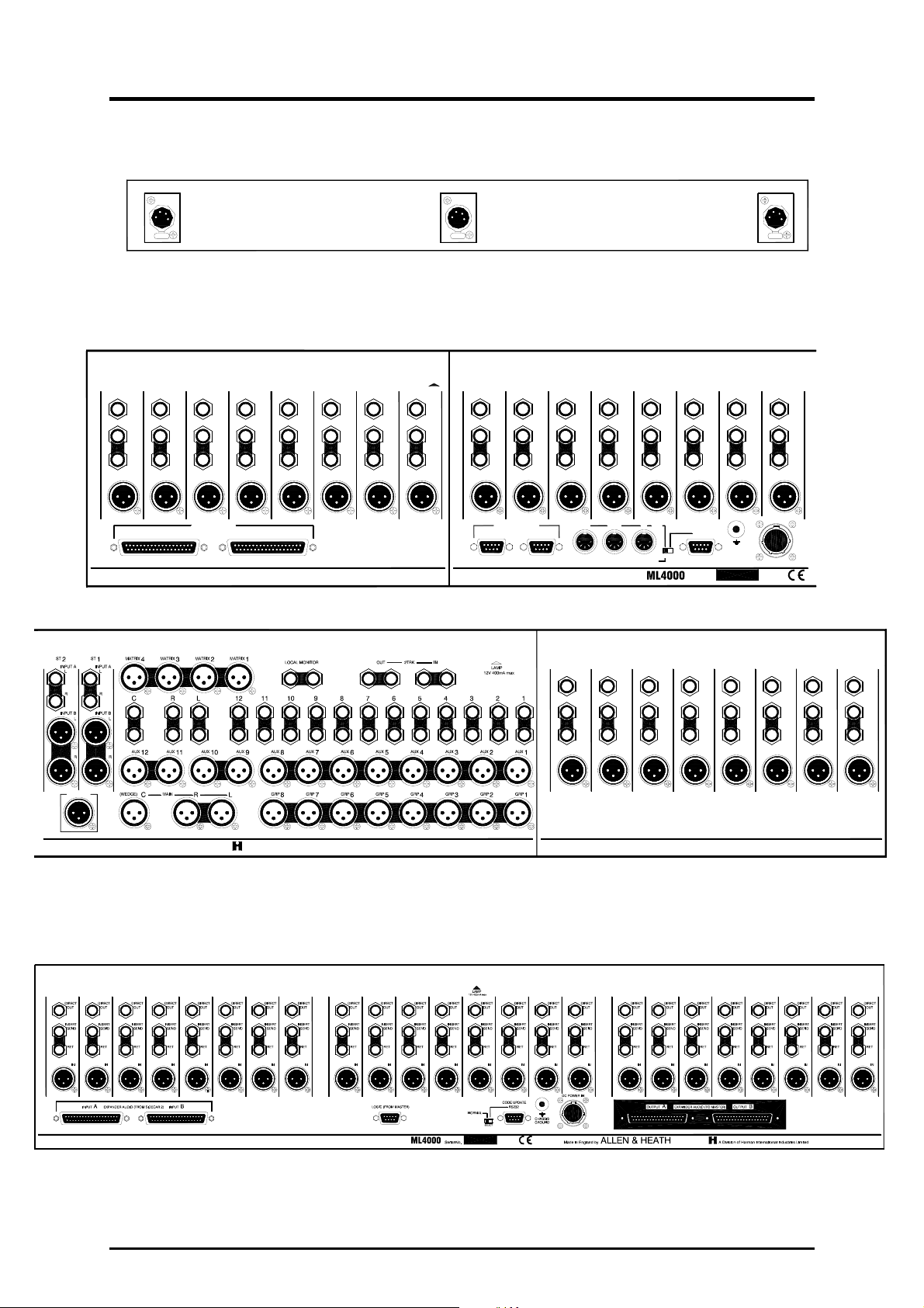
Rear Panel Layouts
Meterpod Gooseneck lamp connectors.
Console Audio, expander, intercom, power, MIDI and logic connectors.
DIRECT
INSERT
OUT
SEND
RET
IN
DIRECTDIRECT
OUT OUT OUT
INSERT
INSERT
SEND
SEND SEND
RET
RET
IN
IN
DIRECT
INSERT
DIRECT
DIRECT
OUT
OUT
INSERT
INSERT
SEND
SEND
RET
RET
RET
IN
IN
IN
OUT OUT
INSERT
SEND
RET RET
DIRECTDIRECT
INSERT
SEND
ININ
DIRECT
OUT
INSERT INSERT
DIRECT
DIRECT
OUT
OUT
INSERT INSERT
RETRET RET RET
DIRECT
OUT
SENDSENDSEND SEND
DIRECT
DIRECT
OUT
INSERT INSERT
OUT
RETRET RETRET
DIRECT
DIRECT
OUT
OUT
INSERT INSERT
SENDSENDSENDSEND
INININININ INININ
INTERCOM
INSERT
INPUT
SEND
RETURN
A
EXPANDER AUDIO
INSERT INSERT
RSR
INPUT
B
RL RL RL
INSERT
INSERT
INSERT
INSERT
INSERT
INSERT
INSERT
INSERT
S
S
S
S
S
S
S
S
R
R
R
R
R
R
R
A Division of Harman International Industries LimitedALLEN & HEATHMade in England by
INSERT
S
R
EXPANDER LOGIC
SIDECAR
2 SIDECAR 1
INSERT
INSERT
S
S
S
R
R
R
OUT THRU IN
DIRECT
OUT
INSERT
SEND
RET RET RET
Expander Sidecar Audio, link to main console, power and logic connectors.
Select MIDI for normal operation !
DIRECT
OUT
INSERT
SEND
CHASSIS
GROUND
DIRECT
OUT OUT
INSERTINSERT
SEND
DC POWER IN
DIRECT
INSERT
SEND
DIRECT
DIRECT
OUT
OUT
INSERT
INSERT
SEND
SEND
RET RET
INININ
ININ
MIDI
RS232
SELECT
Serial No.
DIRECT
DIRECT
OUT
OUT
INSERT
SEND
SEND
RET RET RET
INININ
8 ML4000 Service Manual
Page 9

Technical Specifications
0dBu = 0.775 Vrms, +4dBu = 1.23 Vrms
Operating Levels
Channels......................................... 0dBu Headroom +21dB
Mix .................................................. -2dBu Headroom +23dB
Max XLR output .............................. +23dBu
Frequency Response Referred to 1kHz at +4dBu
Mic to main output (+40dB)............. 20Hz to 30kHz +0/-0.5dB
Line to main output (0dB)................ 20Hz to 30kHz +0/-0.5dB
Distortion @1kHz +14dBu
THD+noise ...................................... < 0.02%
CMRR Common mode rejection @1kHz
Mic (+40dB)..................................... > 80dB
Mic + Pad (0dB) .............................. > 50dB
Crosstalk Referred to driven channel @1kHz
Channel to channel ......................... < -95dB
Mute shutoff .................................... < -90dB
Fader shutoff................................... < -90dB
Noise Performance Measured rms 22Hz to 22kHz unweighted
Mic EIN with 150 ohm source ......... -128dB
Residual output noise ..................... < -98dBu
Mix noise, nothing routed................ < -94dBu
Mix noise, 24 channels routed ........ < -84dBu
Metering
Reading 0................. 0dBu at XLR outputs
LED meters .............. Peak reading, 3 colours
VU meters ................ Ave reading, Illuminated moving coil
Peak indicators ........ 5dB before clip, multi-point sensing
Input meters ............. 5 bar LED (signal, -6, 0, +6, peak)
Group mix meters .... 5 bar LED (signal, -6, 0, +6, peak)
Group/Mtx meters .... VU
L,R,C meters............ VU and 16 bar LED
Lamp Connectors x3
Connector ....................................... XLR-F 4pin
Rating.............................................. 12V 400mA max
Channel Filters
Slope ............................................... 12dB/oct high pass
Frequency ....................................... 20Hz to 400Hz
Mono Equaliser
HF................. +/-15dB, 2kHz to 20kHz shelf
HM................ +/-15dB, 500Hz to 15kHz bell, Q = 1 or 2
LM ................+/-15dB, 35Hz to 1kHz bell, Q = 1 or 2
LF ................. +/-15dB, 20Hz to 200Hz shelf
Stereo Equaliser
HF................. +/-15dB, 12kHz shelf
HM................ +/-15dB, 2.5kHz bell
LM ................+/-15dB, 250Hz bell
LF ................. +/-15dB, 60Hz shelf
Power Supply Model MPS14
Type ........................... External 2U rack or floor mount
Mains input................. 100-230V 50/60Hz universal input
Power consumption.... 500W
Full protection and fan cooling
Built-in combiner for redundant supply
Dimensions Width.............. Depth ...... .....Height
24 Channel 1196 (47”) ...... 781 (30.7”).... 282 (11.1”)
32 Channel 1451 (57”) ...... 781.......... .....282
40 Channel 1706 (67”) ...... 781.......... .....282
48 Channel 1961 (77”) ...... 781.......... .....282
Sidecar 831 (33”) ........ 781.......... .....282
MPS14 psu 483 (19”) ........ 260 (10.2”)....
Weights 24 Channel..... 53 kg (116 lbs)
32 Channel..... 65 kg (143 lbs)
40 Channel..... 75 kg (165 lbs)
48 Channel..... 87 kg (191 lbs)
24 Sidecar...... 40 kg (88 lbs)
MPS14 psu .... 2.5 kg (5 lbs)
INPUTS:
Mic (Pad out)................ XLR.................balanced, pin2+........ 2k ohm ..............variable -60 to -10dBu ........ Max +11dBu
Mic (Pad in).................. ........................ ................................. >20k ohm..........variable -40 to +10dBu .......Max +31dBu
Stereo A ...................... TRS jack .........balanced, tip+........... >20k ohm ..........variable -18 to +6dBu ......... Max +27dBu
Stereo B ...................... XLR................. balanced, pin2+........ >20k ohm..........variable –18 to +6dBu ........ Max +27dBu
2-Track......................... TRS jack .........balanced, tip+ .......... >20k ohm..........+4dBu ................................. Max +25dBu
INSERTS:
Input send .................... TRS jack.........ground comp, tip+ .... <50 ohm............0dBu ................................... Max +21dBu
Input return................... TRS jack ......... balanced, tip+........... >20k ohm..........0dBu ................................... Max +21dBu
Output send ................. TRS jack.........ground comp, tip+ .... <50 ohm............-2dBu .................................. Max +21dBu
Output return................ TRS jack .........balanced, tip+........... >20k ohm..........-2dBu.................................. Max +21dBu
OUTPUTS:
L,R,C............................ XLR.................balanced, pin2+........ <75 ohm............0dBu ................................... Max +23dBu
Grp/Aux 1-12................ XLR................. balanced, pin2+........ <75 ohm............0dBu ................................... Max +23dBu
Matrix 1-4 ..................... XLR................. balanced, pin2+........ <75 ohm............0dBu ................................... Max +23dBu
Direct out...................... TRS jack ......... ground comp, tip+ .... <50 ohm............0dBu ................................... Max +21dBu
2-Track......................... TRS jack .........ground comp, tip+ .... <50 ohm ............0dBu ................................... Max +21dBu
Local Monitor ............... TRS jack.........ground comp, tip+ .... <50 ohm............0dBu ................................... Max +21dBu
Headphones................. TRS jack ......... tip left, ring right........ for stereo headphones >30 ohms
ML4000 Service Manual 9
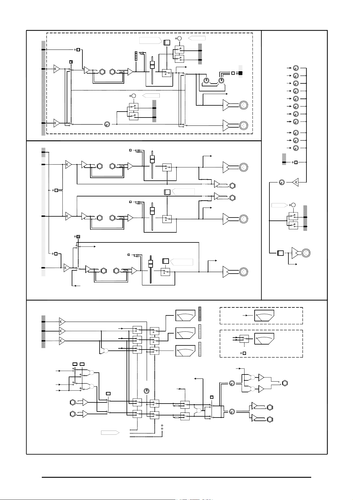
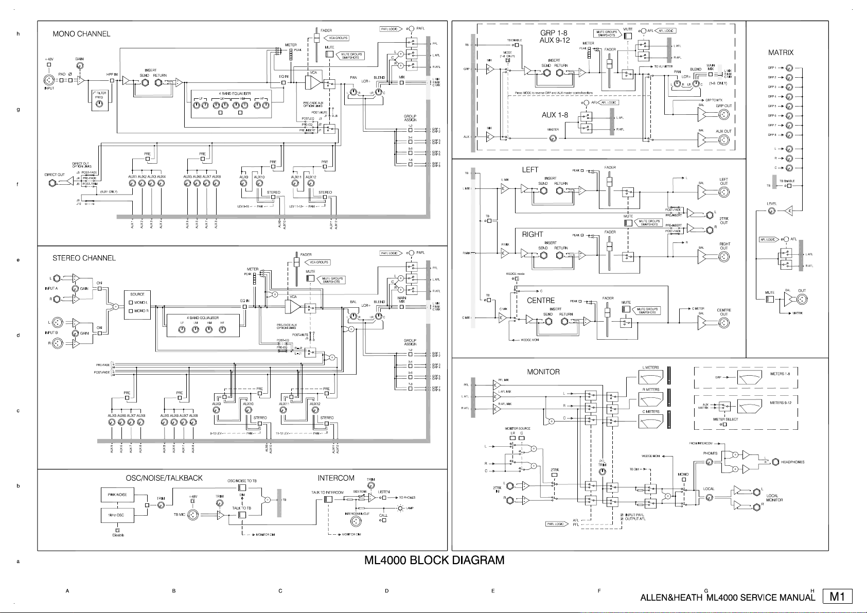
Page 10
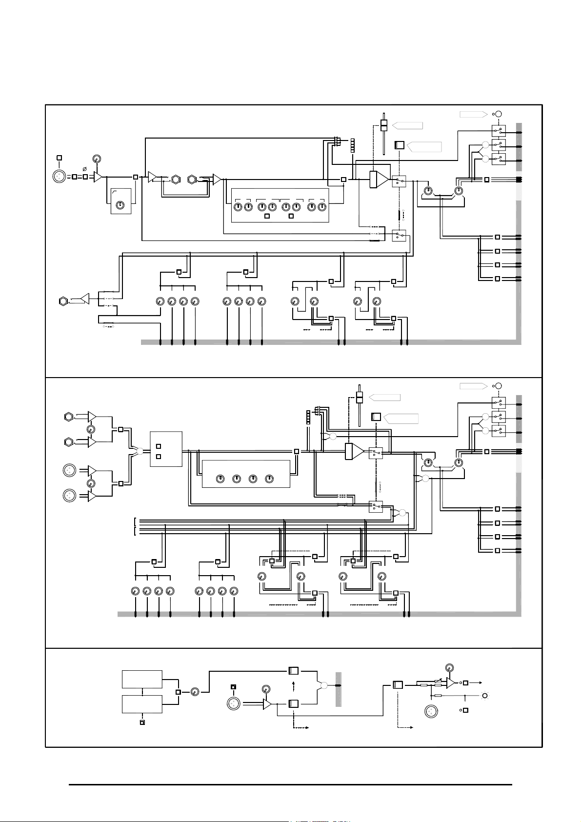
System Block Diagram
MONO CHANNEL
PAD
GAIN
+
-
DIRECT OUT
OPTION LINKS
POST-FADE
J5
PRE-FADE
J4
POST-TRIM
J6
J9
J10
+48V
INPUT
DIRECT OUT
STEREO CHANNEL
+
L
INPUT A
R
L
INPUT B
R
-
GAIN
+
-
+
-
GAIN
+
-
FILTER
FREQ
(AUX1 ONLY)
ON
ON
PRE-FADE
POST-FADE
HPF IN
AUX5
SEND
AUX1
AUX2
AUX 1
AUX 2
SOURCE
MONO L
+
MONO R
L
R
M
L
R
M
PRE
AUX6
AUX7
AUX8 AUX5 AUX6 AUX7 AUX8
INSERT
PRE
AUX3
RETURN
AUX4
AUX 3
PAFL
PFL
L
+
R
+
MIX
GROUP
ASSIGN
1-2
3-4
5-6
7-8
L AFL
R AFL
L MIX
R MIX
C MIX
GRP 1
GRP 2
GRP 3
GRP 4
GRP 5
GRP 6
GRP 7
GRP 8
PAFL
PFL
L
+
R
+
MAIN
MIX
GROUP
ASSIGN
1-2
3-4
5-6
7-8
L AFL
R AFL
L MIX
R MIX
C MIX
GRP 1
GRP 2
GRP 3
GRP 4
GRP 5
GRP 6
GRP 7
GRP 8
+
-
LF LM HF
4 BAND EQUALISER
HM
EQ IN
METER
PEAK
PRE-FADE AUX
OPTION LINKS
POST-EQ
PRE-EQ
PRE-INSERT
VCA
POST-MUTE
J2
J1
FADER
J3
VCA GROUPS
MUTE
J7
J8
MUTE GROUPS
SNAPSHOTS
PAN
L RLRC
LCR+
PAFL LOGIC
C
BLEND
PRE
FADER
J3
AUX12
PAN
VCA GROUPS
MUTE
AUX12
PRE
STEREO
MUTE GROUPS
SNAPSHOTS
PRE
STEREO
AUX11
AUX12
BAL BLEND
L RLRC
+
+
PAFL LOGIC
C
LCR+
PRE
AUX5
AUX6
AUX7
AUX8
AUX9
AUX10
AUX11
STEREO
AUX9
+
PRE-FADE AUX
OPTION LINKS
POST-EQ
PRE-EQ
AUX11
AUX10
LEV 11-12
VCA
POST-MUTE
R=J2
L=J1
LEV 9-10
PAN
AUX 4
AUX 5
AUX 6
AUX 7
AUX 8
METER
PEAK
EQ IN
4 BAND EQUALISER
LF
LM HM HF
PRE
AUX9
PRE
AUX10
STEREO
AUX 5
AUX 6
AUX 7
AUX 8
OSC/NOISE/TALKBACK
PINK NOISE
1kHz OSC
Disable
TRIM
9-10 LEV
AUX 5
AUX 6
AUX 7
AUX 8
PAN
11-12 LEV
AUX9
AUX10
OSC/NOISE TO TB
DIM
TALK TO TB
+
-
MONITOR DIM
TB
+
TB MIC
+48V
TRIM
PAN
AUX11
INTERCOM
TALK TO INTERCOM
AUX12
INTERCOM IN/OUT
MONITOR DIM
SIDETONE
TRIM
LISTEN
-
+
TO PHONES
LAMP
CALL
10 ML4000 Service Manual
Page 11
GRP
AUX
L MIX
R MIX
PEAK
+
-
+
-
+
-
METER
MUTE GROUPS
SNAPSHOTS
AFL
TB
TB ENABLE
MODE
(1-8 ONLY)
MIX
Press MODE to reverse GRP and AUX master control sections
GRP 1-8
AUX 9-12
INSERT
SEND
RETURN
AUX 1-8
MIX
TB
TB
LEFT
L MIX
RIGHT
R MIX
WEDGE mode
SEND
SEND
MASTER
INSERT
INSERT
PEAK
RETURN
PEAK
RETURN
FADER
AFL LOGIC
FADER
FADER
L AFL
R AFL
MUTE
MUTE
AFL
MUTE GROUPS
SNAPSHOTS
AFL LOGIC
TO VU METER
POST-FADE
PRE-INSERT
PRE-INSERT
POST-FADE
L AFL
R AFL
BLEND
PAN
LCR+
L RLR C
BAL
BAL
L
BAL
R
BAL
MAIN
MIX
(1-8 ONLY)
GRP TO MTX
GRP OUT
AUX OUT
L
R
L MIX
R MIX
C MIX
LEFT
OUT
2TRK
OUT
RIGHT
OUT
MATRIX
GRP 1
GRP 2
GRP 3
GRP 4
GRP 5
GRP 6
GRP 7
GRP 8
TB
LEVEL
AFL LOGIC
L
R
C
TB ENABLE
AFL
L AFL
R AFL
C MIX
PFL
L AFL
R AFL
BAL
TB
C MIX
PFL MIX
L AFL MIX
R AFL MIX
MONITOR SOURCE
LR
L
R
C
L
2TRK
IN
R
C
CENTRE
WEDGE MON
MONITOR
C
+
+
+
-
+
-
INSERT
SEND
+
PAFL LOGIC
2TRK
RETURN
L
R
C
PEAK
AFL
PFL
FADER
MUTE
MUTE GROUPS
+
-
SNAPSHOTS
C METER
CENTRE
BAL
OUT
L METERS
GRP
R METERS
AUX
C METERS
MATRIX
METER SELECT
FROM INTERCOM
PFL
TRIM
TB DIM
WEDGE MON
PHONES
MONO
+
+
LOCAL
+
INPUT PAFL
OUTPUT AFL
MUTE
L
R
L
LOCAL
MONITOR
R
METERS 1-8
METERS 9-12
OUT
MATRIX
HEADPHONES
ML4000 Service Manual 11
Page 12
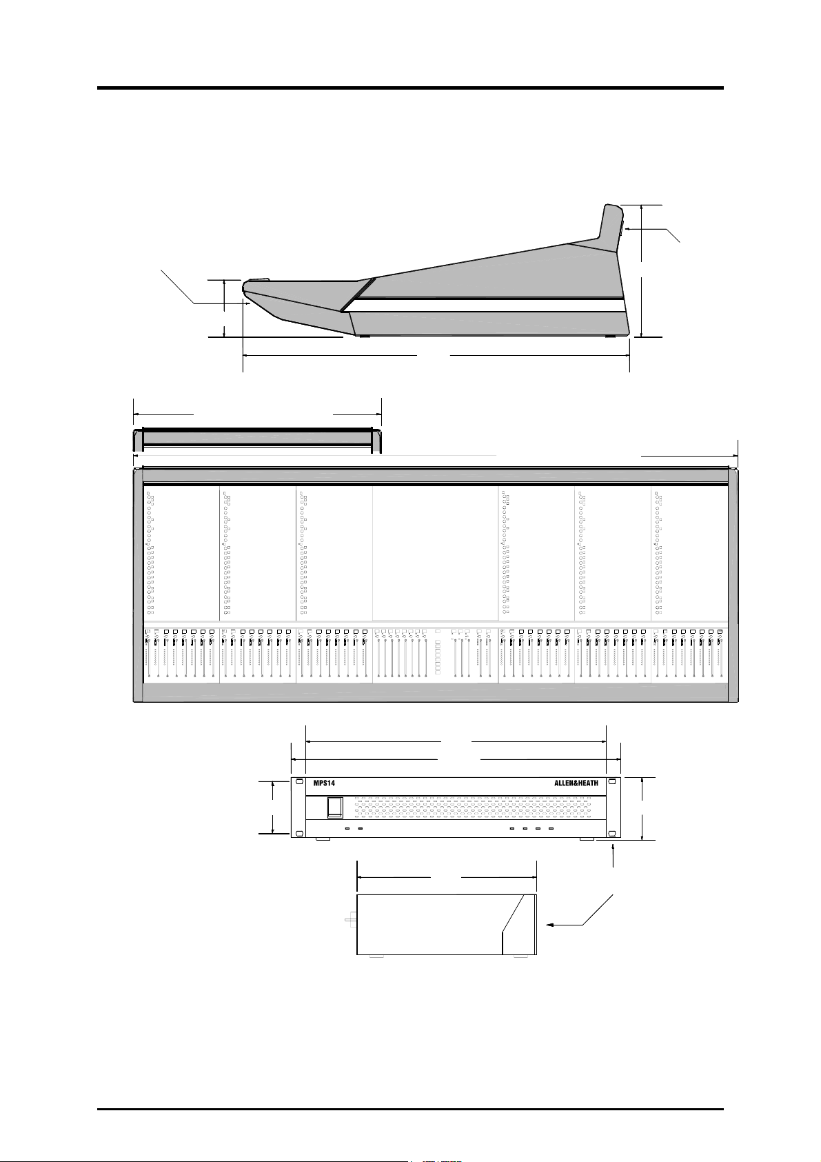
Installation Details
Weights 24 Channel 53 kg (116 lbs)
32 Channel 65 kg (143 lbs)
40 Channel 75 kg (165 lbs)
48 Channel 87 kg (191 lbs)
24 Channel sidecar 40 kg (88 lbs)
MPS14 psu 2.5 kg (5 lbs)
HEADPHONES SOCKET
UNDER ARMREST
130
ML4000-24SC = 831
LAMP SOCKETS
282
781
ML4000-24 = 1196
ML4000-32 = 1451
ML4000-40 = 1706
ML4000-48 = 1961
440
482.6
FC 76.2
263
REMOVABLE RACK EARS
90
2U HEIGHT
Refer to the power supply user guide for safety and installation instructions. Heed all
warnings printed in the user guide and on the power unit.
Refer to the sidecar user guide for instructions on connecting the sidecar expander to the
console.
12 ML4000 Service Manual
Page 13

Earthing
The connection to earth (ground) in an audio system is important for two reasons:
SAFETY - To protect the operator from high voltage shock, and
1.
2.
AUDIO PERFORMANCE - To minimise the effect of earth (ground) loops
which result in audible hum and buzz, and to shield the audio signals from interference.
For safety it is important that all equipment earths are connected to mains earth so that
exposed metal parts are prevented from carrying high voltage which can injure or even
kill the operator. It is recommended that the engineer check the continuity of the safety
earth from all points in the system including microphone bodies, guitar strings,
connector cases, equipment panels and so on.
The same earth is also used to shield audio cables from external interference such as
the hum fields associated with power transformers, lighting dimmer buzz, and computer
radiation. Problems arise when the signal sees more than one path to mains earth. An
earth loop results causing current to flow between the different earth paths. This
condition is usually detected as a mains frequency audible hum or buzz.
To ensure safe and trouble-free operation we recommend the following:
Use a clean mains outlet for the audio system. Keep the audio
equipment mains feed separate from that powering ‘dirty’ equipment such as air
conditioning and lighting systems, motors and vending machines.
Use star point earthing. It is best to install a ‘star point’ system where the
individual earths to the equipment racks and equipment areas are separately run from a
solid central reference earth point.
Have your mains system checked by a qualified electrician. If the
supply earthing is solid to start with you are less likely to experience problems.
Do not remove the earth connection from the console mains plug.
The console chassis is connected to mains earth through the power cable to ensure
your safety. Audio 0V is connected to the console chassis internally. If problems are
encountered with earth loops operate the audio ‘ground lift’ switch on the power supply
or connected equipment, or disconnect the cable screens at one end, usually at the
destination.
Avoid induced interference. To prevent interference pickup keep audio cables
away from mains power units, cables and distribution boards, motors, lighting and
computer cables and equipment, and any other heavy duty electrical equipment. Where
this cannot be avoided cross the audio and ‘dirty’ equipment cables at right angles to
minimise interference.
Use low impedance sources such as microphones and line level equipment
rated at 200 ohms or less to reduce susceptibility to interference. The console outputs
are designed to operate at very low impedance to minimise interference problems.
Use balanced connections where possible as these provide further
immunity by cancelling out interference that may be picked up on long cable runs. To
connect an unbalanced source to a balanced console input, link the cold input (XLR pin
3 or jack ring) to 0V earth (XLR pin 1 or jack sleeve) at the console. To connect a
balanced console output to an unbalanced destination, link the cold output to 0V earth at
the console.
Use good quality cables and connectors and check for correct wiring and
reliable solder joints. Allow sufficient cable loop to prevent damage through stretching.
ML4000 Service Manual 13
Page 14
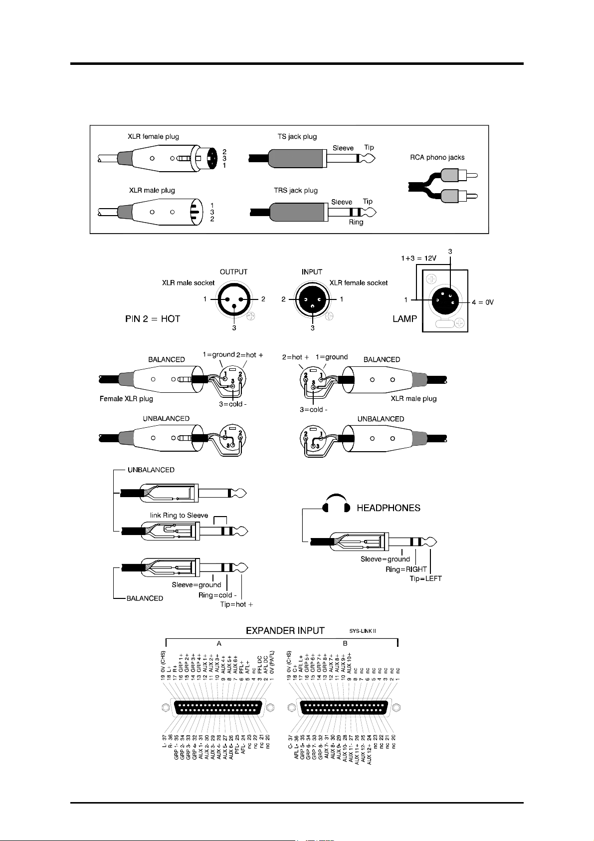
Audio Connector Types and Wiring
14 ML4000 Service Manual
Page 15
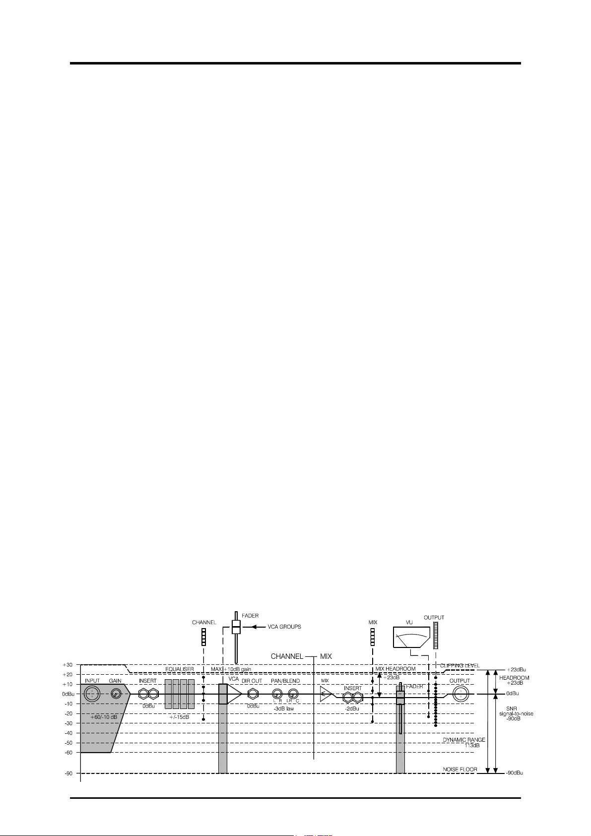
Gain Structure Notes for the user.
How the levels between the different signal stages
are set up is referred to as the gain structure. For
best performance it is important that the connected
source signals are matched to the ‘normal operating
level’ of the console. Similarly the levels of the
connected amplifiers and destination equipment
should be correctly matched to the console outputs.
If set too high then the signal peaks will be clipped
resulting in distortion, and if set too low then the
signal-to-noise performance will be degraded
resulting in excessive background hiss and noise.
Using the Meters. The ML4000 provides metering
at all important stages through the signal chain. For
best results operate the console with the LED bar
meters averaging around ‘0’ allowing the loudest
moments to reach ‘+6’. Reduce the gain if the red
peak LEDs start to flash. Note that the peak leds
light 5dB before actual clipping to warn that you are
nearing distortion and should reduce gain. The
LED bar meters have a peak response with fast
attack and slow release so that fast musical
transients are accurately displayed. The VU meters
have a slower attack so that the average levels are
better displayed. Both types of metering are useful
in live sound mixing.
Matching a Source to the Console. Start by
turning down the channel fader and send levels to
prevent unexpected loud volumes reaching the
main speakers and monitors. Adjust the GAIN
control for an average ‘0’ reading on the channel
meter. Press PAFL (in PFL mode) to listen to the
signal using headphones, local or wedge monitor,
and to view its level on the main LED and VU
meters. Once the gain is correctly set you can raise
the levels to bring the channel into the mix. Note
that you may need to adjust the gain if you make
significant changes to the EQ. Make sure that any
equipment inserted into the channel is set to
operate around 0dBu line level. It is best to first set
the gain with inserted signal processors such as
compressors switched to bypass.
Matching the Console to Destination Equipment.
The console produces a standard XLR output level
of 0dBu for a meter reading of ‘0’. It can produce a
maximum of +23dBu and is therefore well suited to
driving equipment operating at nominal 0dBu or
+4dBu while providing plenty of headroom. If you
are connecting directly to a sensitive power
amplifier it is advisable to turn down its input trim
control if the normal console level is too high.
Simply turning down the console output faders
degrades the output stage noise performance and
reduces the resolution of the fader movement. The
output faders are best operated around ‘-10’ to ‘0’
for loudest average volume required. This allows
plenty of additional headroom if you need it.
Terminology. The normal operating level is the
optimum signal level for best console performance,
indicated by ‘0’ meter readings and resulting in the
0dBu output level. The channels operate at 0dBu
and the mix stages at –2dBu for extended
headroom. Headroom is the extra level available
above normal to allow for loud peaks before the
signal becomes clipped resulting in audible
distortion. The signal-to-noise ratio (SNR) is the
difference measured in dB between normal level
and residual noise floor (hiss) produced by the
console electronics. The dynamic range is the
sum of headroom and SNR representing the
maximum signal range possible from quietest to
loudest.
Using the VCA Groups. Assigning a channel to
one or more VCA groups lets those group faders
control the level of its VCA element. Each fader
provides up to +10dB boost. Note that the channel
VCA allows a maximum combined fader boost of
+10dB. Any more is simply ignored. It is best to
operate the VCA group faders around their nominal
‘0’ position. You can also use a VCA group to
reduce the overall level of a hot mix without having
to adjust all the channel faders.
ML4000 Service Manual
15
Page 16
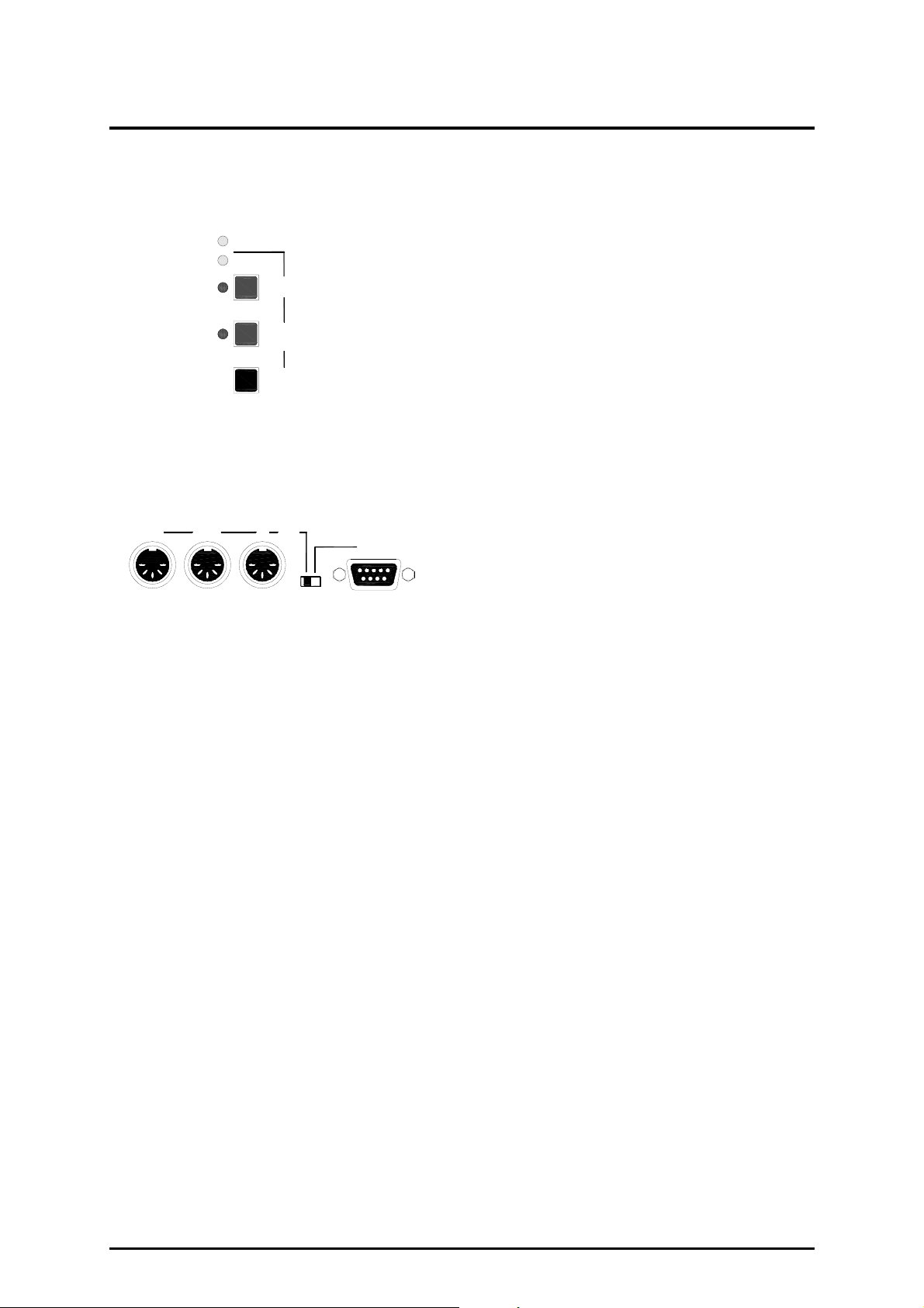
MIDI
MIDI
RS232
DUMP
EDIT SAFES
Use CH MUTES
MIDI CH
Hold and press CH1>16 MUTE
OUT INTHRU
MIDI
RS232
SELECT
The MIDI Cables
Use standard 5-pin 180 degree DIN type male-tomale MIDI cables. These should be available from
your local audio dealer or music shop. The cables
should not exceed 15 meters (50 feet) in length.
To control external equipment plug console MIDI
OUT to external equipment MIDI IN. To control the
console plug external equipment MIDI OUT or
THRU to console MIDI in. To pass MIDI through
the console to other equipment plug console MIDI
THRU to equipment MIDI IN.
Make sure the same MIDI channel number is
selected on the console and external equipment
you want the console to communicate with.
MIDI Overview
The ML4000 includes a Musical Instrument Digital
Interface (MIDI) port. Standard 5-pin IN, THRU and
OUT sockets allow connection to external MIDI
equipment such as computer show control systems,
sequencers, instruments and data archiving
devices. Applications include sophisticated ‘handsoff’ scene control, effects and instrument patch
control, switching of signal processing remote
controllers, and archiving of the console settings
and memories for later re-use.
What the console MIDI can do :
9 Turn channel mutes on and off
9 Recall snapshot memories
9 Snapshot program change messages
9 AFL SysEx messages for BSS & dbx
controllers
9 Archive console settings and memories
What the console MIDI cannot do :
8 Turn Mute Groups on and off
8 Turn VCA group mutes on and off
8 Assign channels to VCA groups
8 Control VCA fader levels
The capabilities of the console automation system
are subject to continual development and new
features may be added in time. The latest
operating software is available on the Allen & Heath
Internet site together with loading instructions.
Selecting MIDI Operation
For MIDI operation make sure the rear panel switch
is set to the MIDI position. The RS232 setting is
only used when updating the console operating
software to a new version, or with the Allen & Heath
ML4 Archiver utility for the PC.
Changing the MIDI Channel Number
Hold down the master section MIDI CH key. The
current MIDI channel number is displayed on one of
the CH1 to 16 SAFE/EDIT LEDs. The LED flashes
to attract your attention. Simply press one of the
CH1 to 16 MUTE keys while holding down MIDI CH
to change the MIDI channel number. The channel
mute is not affected during this operation.
16 ML4000 Service Manual
Page 17
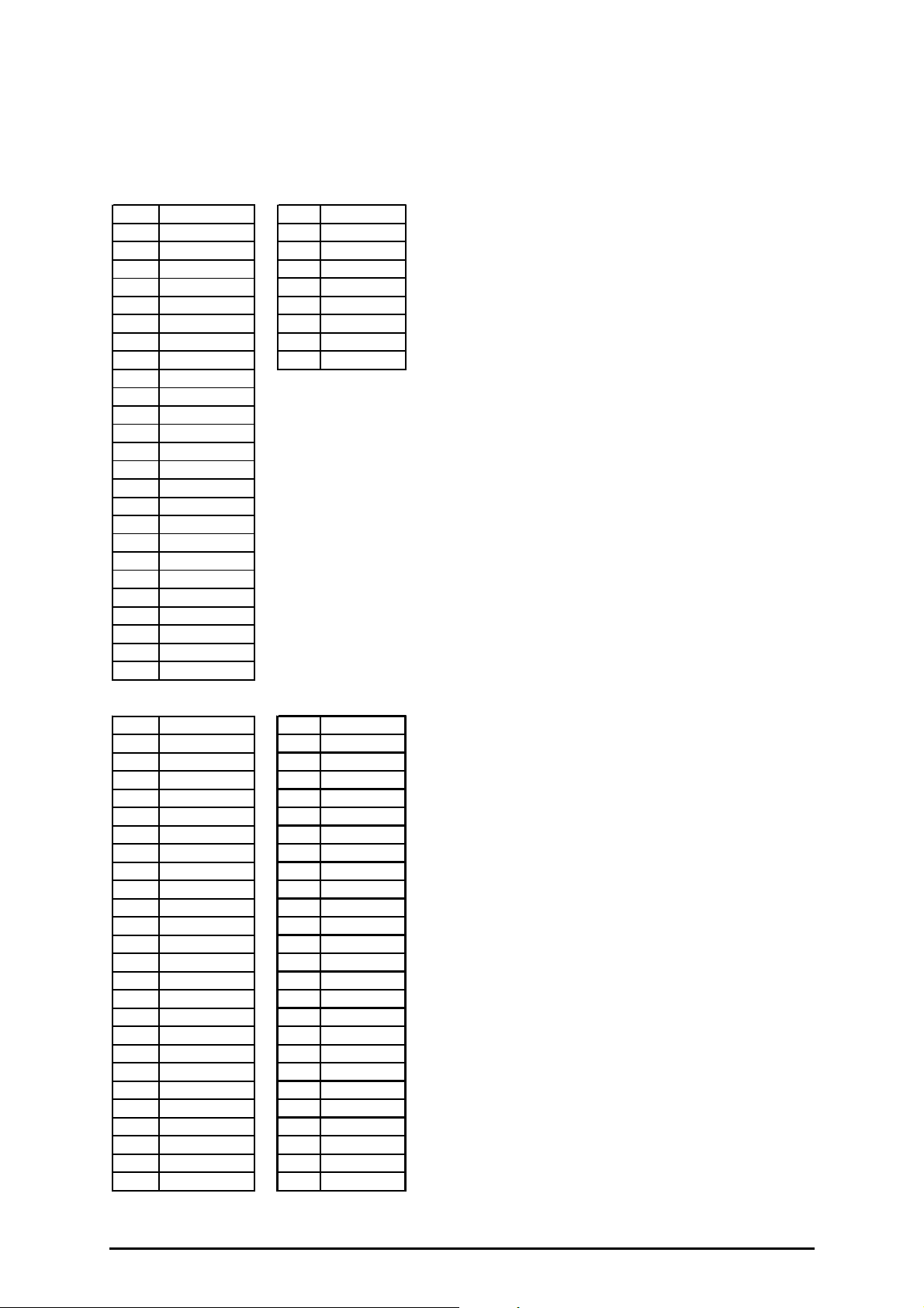
HEX MUTE HEX MUTE
00 GRP/AUX 1 50 STEREO 1
01 GRP/AUX 2 51 STEREO 2
02 GRP/AUX 3 52
03 GRP/AUX 4 53
04 GRP/AUX 5 54 MAIN L
05 GRP/AUX 6 55 MAIN R
06 GRP/AUX 7 56 MAIN C
07 GRP/AUX 8
08 AUX 9
09 AUX 10
0A AUX 11
0B AUX 12
0C
0D
0E
0F
10 MATRIX 1
11 MATRIX 2
12 MATRIX 3
13 MATRIX 4
14
15
16
17
Channel Mutes
Pressing any input or output channel MUTE switch
transmits a MIDI Note On message. Similarly,
receiving a MIDI Note On message will turn the
associated channel mute on or off, unless the
channel has been made automation safe.
Console mutes are mapped to MIDI Note numbers
as shown in the table. Running status is supported
on receive and transmit.
Transmit. Pressing a channel MUTE switch
transmits the following Note On messages:
9n cc vv 9n cc 00
Where n = console MIDI channel number
cc = input or output channel number
vv = 3FH for mute off, 7FH for mute on
Receive. The console responds to the following
MIDI Note On message:
9n cc vv (00 is ignored)
Where vv < 40 = mute off,
40 <= vv <= 7F = mute on
Snapshot Memories
Recalling a snapshot will transmit a MIDI Program
Change message. Receiving a Program Change
message will recall a snapshot.
HEX MUTE HEX MUTE
20 CH 1 38 CH 25
21 CH 2 39 CH 26
22 CH 3 3A CH 27
23 CH 4 3B CH 28
24 CH 5 3C CH 29
25 CH 6 3D CH 30
26 CH 7 3E CH 31
27 CH 8 3F CH 32
28 CH 9 40 CH 33
29 CH 10 41 CH 34
2A CH 11 42 CH 35
2B CH 12 43 CH 36
2C CH 13 44 CH 37
2D CH 14 45 CH 38
2E CH 15 46 CH 39
2F CH 16 47 CH 40
30 CH 17 48 CH 41
31 CH 18 49 CH 42
32 CH 19 4A CH 43
33 CH 20 4B CH 44
34 CH 21 4C CH 45
35 CH 22 4D CH 46
36 CH 23 4E CH 47
37 CH 24 4F CH 48
Snapshot numbers 1 to 128 are mapped to MIDI
Program Change numbers 0 to 127. Running
status is supported on receive and transmit.
Transmit and Receive. The message format is:
Cn pp
Where n = console MIDI channel number
pp = console snapshot number 00 to 7F
MIDI AFL Messages
SysEx message strings are transmitted each time
an output channel AFL switch is selected or
released. These are for use with BSS and dbx
speaker management systems to automatically
select the remote control surface associated with
the output being AFL monitored.
BSS Omnidrive
F0 00 20 18 7F 20 tx_event F7
dbx Drive Rack
F0 00 01 1E 7F 7F 20 tx_event F7
These messages are subject to further development
and addition. Please check the Allen & Heath Web
site for the latest information.
ML4000 Service Manual
17
Page 18

Archiving the Console Settings
The console settings can be saved to an external
device such as a MIDI sequencer or data archiver
using the dump out facility. Saved settings can be
loaded back into the console using dump in. This is
ideal when you want to archive the settings to use
at a later date, for example a re-run of a previous
performance. You can also use the dump facility to
program additional ML4000 consoles, for example
when setting up duplicate shows or swapping
consoles around. Simply link MIDI OUT from one to
MIDI IN of the other and action the dump out facility.
Settings which are archived :
9 Current mute settings
9 Current Mute group assignments
9 Current VCA group assignments
9 Automation safes
9 All snapshot memories
Settings which are not archived :
8 Current console operating mode
8 Current PAFL selection and settings
MIDI Dump Out
Connect the console to a suitable MIDI archiving
device. Set the same MIDI channel number on
both. Check the rear switch is set to MIDI. Press
the DUMP key. The console dumps the current
settings and memory contents using a SysEx
message string. During this time the DUMP and
MIDI LEDs light to show that data is being sent via
the MIDI port. Note that this operation can take up
to 10 seconds during which time the console mutes,
assignment and P/AFL operations are interrupted.
MIDI Dump In
Connect the console to the MIDI archiving device.
Set the same MIDI channel number on both. Check
the rear switch is set to MIDI. Start the process
using the MIDI archiver. The console current
settings and memory contents are overwritten.
During this time the DUMP and MIDI LEDs light to
show that data is being received by the console.
Note that this operation can take a while during
which time the console mute, assignment and PAFL
operations are interrupted.
MIDI Dump Message Format
The format for dump out and in is identical. The
dump data string is made up of multiple System
Exclusive messages (known as packets) which
contain the console information.
Transmit and Receive. The format for a single
packet is as follows:
F0 <SysEx header> <packet type> <packet
number> <data> <checksum> F7
<SysEx header> = 00 00 1A 50 07 VV vv nn
Where VV = software version number – unit
vv = software version number – decimal
nn = console MIDI channel number
<packet no.> = packet number from 0 to 127
<data> = block of console data (7-bit format)
<checksum> = checksum to allow error detection
MIDI Dump Errors
If the console or connected equipment fails to
respond to a MIDI dump then check:
The MIDI cable is good and correctly plugged
The same MIDI channel number is selected
The rear panel switch is set to MIDI
Try again
Allen & Heath ML4 Archiver
The ML4Archiver Windows™ utility for the PC can
be downloaded from the Allen & Heath Internet site.
This can be used to archive data to and from the
PC via MIDI or RS232.
The program also includes the useful Snapshot
Manager which lets you store and recall the console
mute settings and VCA group assignments from the
128 internal snapshot memories. The snapshots
cannot be accessed from the console control panel
itself. The archiver provides this extra feature.
Check the Allen & Heath Web site for further details
and loading instructions.
If you are using a MIDI sequencer to record the
dump out data string then make sure you play it
back at the same speed you recorded it. If you
dump it back into the console faster than it was
recorded some data may not load correctly.
18 ML4000 Service Manual
Page 19

Console Computer and Operating Software
Operating Software Version Number
You can check the current version number of the
ML4000 software running on the console using a
PC connected via RS232. Instructions for this are
provided on the Allen & Heath Internet site.
Loading New Operating Software
Check the Allen & Heath Web site for the latest
version of console software. New software is
loaded from a PC via the RS232 port.
IMPORTANT ! The current console settings and
snapshots may be lost when you load new
operating software. If you wish to keep your
settings and snapshot contents, first archive them
using the dump out facility. Restore these after
loading the new software by using dump in.
Download the software from the Allen & Heath Web
site to your PC computer. Connect the PC RS232
port to the console RS232 port using a standard
pin-to-pin (not null modem) 9-pin serial cable. Set
the console rear panel switch to the RS232 position.
Power up the console. The console awaits data
from the PC. Follow the instructions provided on
the Web site for loading the new software into the
console. When completed make sure you set the
console rear panel switch back to its normal
operating position, typically MIDI.
Power Up and Power Down
The console settings are saved when power is
removed. On power up these settings are restored.
To Reset the Console Settings
Hold down the MIDI CH and EDIT SAFES keys
together while turning on the console to reset all
current settings. This does not affect the contents
of the snapshot memories. The default settings are
restored:
Selects normal console operating mode
Clears all current Mute Group assignments
Clears all current VCA Group assignments
Clears all channel automation safes
To Reset the Snapshot Memories
Hold down the MIDI CH and DUMP keys together
while turning the console on to clear all the
snapshot memories. This does not affect the
current console settings. For all snapshots reset:
Clears all stored mutes
Clears all stored VCA Group assignments
To reset all Settings and Memories
Hold down the MIDI CH, the EDIT SAFES and
DUMP keys together while turning the console on to
clear all current settings and the memories.
Important Note:
1. If a sidecar expander is used with the ML4000 make sure it is running the same version of
software as the master console.
2. If it is necessary to replace the CPU assembly make sure the jumper links are correctly set on
the replacement assembly. These are set differently for the master and sidecar consoles.
Refer to drawing D44 for details.
3. If it is necessary to replace the MIDI/PSU assembly make sure the jumper links are correctly
set on the replacement assembly. These are set differently for the master and sidecar
consoles. Refer to drawing D42 for details.
ML4000 Service Manual
19
Page 20

Internal Options Links
The ML4000 is designed to offer the utmost flexibility to satisfy the application without modification.
However, the following internal link options are provided to allow customisation to satisfy the more
specialist applications or personal preferences. Remember to set these internal links according to
the user requirement if replacing assemblies while carrying out service work:
Mono channel AUX options The pre-fade sends are set pre-insert, pre-EQ, post-mute
as standard. Jumper links on the mono circuit cards can be replugged to configure
post-insert, pre-EQ and/or pre-mute. Refer to drawing D1 and D3.
Stereo channel AUX options The pre-fade sends are set pre-EQ, post-mute as
standard. Jumper links on the stereo circuit cards can be replugged to configure postEQ and/or pre-mute. Refer to drawing D5 and D7.
Mono channel DIRECT outputs These are derived post channel fader as standard. A
jumper link on each card can be replugged to configure pre-fader or post-fade with level
trim. The direct out pre-fade source is the same as that configured to feed the aux
sends. The level trim option disables the channel Aux1 send and uses its send as the
direct out level control. Two links need to be set in this case, one to send the direct
output signal through the send control, the other to disable the Aux1 send from the
channel. Refer to drawing D1.
2-track output source These are set post master insert and fader as standard. Two
pairs of jumper links can be replugged to derive the output pre-insert, pre-fader. Refer
to drawing D18 and D20.
Internal Assembly Assignments
The following assignment links need to be set according to assembly position in the console.
These should not need changing unless a replacement assembly has been fitted.
Group 1,3,5,7 buss assignment Zero ohm links determine which busses feed the
group and aux mix amps. Refer to drawing D11 and D12.
Group 2,4,6,8 buss assignment Zero ohm links determine which busses feed the
group and aux mix amps. Refer to drawing D14 and D15.
VU meters 1-8 The same assembly type is used for meters 1-4 and 5-8. The position
in the console is determined by soldered links. Refer to drawings D38, D39 and D40.
MIDI/PSU assignment Position two pairs of links according to whether the assembly is
fitted to a console or a sidecar. Refer to drawing D42.
CPU assignment Position the three links according to the console type as shown on
drawing D44
20 ML4000 Service Manual
Page 21

The Range
ML4000-24 24 mono, 2 dual stereo input - Live sound console
ML4000-32 32 mono, 2 dual stereo input - Live sound console
ML4000-40 40 mono, 2 dual stereo input - Live sound console
ML4000-48 48 mono, 2 dual stereo input - Live sound console
ML4000-24SC 24 mono input - Expander sidecar
MPS14 2U power supply unit - For ML5000 console
002-583 2.8 metre DC power lead – To connect MPS14 power supply to console
002-584 0.5 metre DC combiner lead - To link two MPS14 power supplies
002-617 2.8 metre 37way Audio cable - To link sidecar to console
AL4155 2.8 meter 9way Logic cable - To link sidecar to console
AP4314 ML4000 Console User Guide
AP4373 ML4000 Sidecar User Guide
AP4316 ML4000 Console Service Manual
AP3898 MPS14 Power Supply User Guide
AP4143 MPS14 Power Supply Service Manual
AL4061 Gooseneck lamp 18”
Ordering Spares
Spare parts and replacement assemblies can be ordered from Allen & Heath. When
doing this please provide full details including console size and model, serial number
and description of the part.
If you are ordering replacement assemblies please quote the channel position in the
console. Several assemblies need to be link assigned according to position. Failure to
observe the correct link setting may result in incorrect console operation. Details of
these link assignments are printed on the relevant circuit diagrams later in this manual.
If you have any queries about the automation system please quote the console
operating system version number.
ML4000 Service Manual
Technical support is available through the Allen & Heath distribution network or direct
from Allen & Heath. Many resources are available from the Allen & Heath Internet Web
site:
www.allen-heath.com
spares@allen-heath.com
21
Page 22

ORDERING AN ML4000 SPARES KIT
It is recommended that the spares kit order code 002-699 is held and maintained by the service agent
to enable in-field service repairs to the ML4000 independent of the ALLEN & HEATH factory.
Commonly available items such as resistors, capacitors, tools and soldering equipment are not
included. The contents of the kit are listed below and are supplied in a cabinet of drawers. Individual
spare parts may be ordered. Please quote the description and order code for the part required.
Fixings:
DESCRIPTION ORDER CODE QTY
Screw 4AB x 5/16” CSK Pozi Black AB0059 10
Screw M3 x 6 Pan Torx Black AB0072 5
Screw M3 x 8 Pan Torx Black AB0073 10
Screw M3 x 8 CSK Torx Black AB0074 10
Nylock Nut M3 AB0102 20
Nylock Nut M4 AB0105 10
Screw M3 x 4 Pan Torx Black AB0233 10
Screw 4AB x 1/2" Pan Torx Black AB0250 10
Screw M6 x 20 CSK Torx Black AB0310 5
Screw 6B x 3/8 CSK Pozi Zinc AB2082 20
Screw 6B x ¼” CSK Pozi Zinc AB2083 10
Screw 8B x 3/8 CSK Pozi Black AB2085 10
Screw M4 x 12 CSK Torx Black AB2086 5
Screw 3.5 x 25 Chipboard Pan Pozi AB2647 5
Screw M4 x 8 CSK Torx Black AB2777 5
Screw 6B x 5/16 Pan Torx Black AB2809 20
Screw M3 x 4 CSK Torx Black AB2811 20
Screw M2 x 4 CSK Pozi Black AB3329 10
Screw M3 x 4 TT Hex Head Black AB3837 20
Screw M6 x 12 CSK Torx Zinc AB4036 5
Screw 6B x 3/8 Flange Headed Pozi Black AB4037 10
Washer M4 Finishing AB4376 5
Spacer LED 10.7mm AB4383 1
Pot Nut 9mm AB8050 50
Knobs and caps:
DESCRIPTION ORDER CODE QTY
Knob Red & Grey 11mm AJ2074 10
Knob Blue & Grey 11mm AJ2075 30
Knob Light Blue & Grey 11mm AJ2076 30
Knob Green & Grey 11mm AJ2077 15
Knob Dark Grey & Grey 11mm AJ2078 15
Knob Yellow & Grey 11mm AJ2079 10
22 ML4000 Service Manual
Page 23
Knob Brown & Grey 11mm AJ2080 10
Button 10x5mm Rectangular Grey AJ2865 2
Button 10x5mm Rectangular Black AJ3228 1
Button 5mm Square Red AJ3488 15
Fader Knob 11mm Black + White Line AJ3503 15
Switch Cap Light Blue/Grey Offset AJ3863 20
Button Illuminated Red AJ3949 2
Switch Cap Light Blue/White Offset AJ3950 15
Button 6x6mm Square White AJ3951 10
Button 6x6mm Square Light Grey AJ3952 5
Button 6x6mm Square Red AJ3953 2
Button 6x6mm Square Black AJ3954 5
Button 8mm Round Light Grey AJ3955 10
Fader Knob 11mm White+Black Line AJ8078 5
Fader Knob 11mm Red+Black Line AJ8079 10
Fader Knob 11mm Blue+Black Line AJ8081 10
Button Illuminated White AJ8107 10
Faders, Potentiometers, Switches and connectors:
Pot 10KC x 2 (103C 14mm wide) AI0150 2
Fader 10KA Dust 60mm AI3497 5
Pot 20KK (203K 11mm wide) AI8003 10
Pot 20KB C/D (203B 11mm wide) AI8004 10
Pot 200KC x 2 (204C 11mm wide) AI8005 5
Pot 20KB x 2 centre click (14mm wide) AI8006 3
Pot 20KK x 2 (203K 14mm wide) AI8007 1
Pot 10K (103AC 14mm wide) AI8008 5
Pot 200KC x 2 (204C 14mm wide) AI8009 5
Fader 10KSPE 100mm AI8109 3
Pot 5K (502RD 11mm wide) AI8111 5
Fader 10KB 100mm AI8175 10
Switch 2PCO Latching AL0162 15
Jack Socket Headphone AL0328 1
Switch 4PCO Latching AL0333 10
Switch 2PCO Momentary AL0374 10
XLR 3 Pin Female Vertical PCB Mount AL2410 5
XLR 3 Pin Male Vertical PCB Mount AL2411 5
Switch Slide MINI SPDT PCB AL3081 1
Jack Socket ¼” Stereo Unswitched AL3407 15
Jack Socket ¼” Stereo Switched AL3410 20
Switch 2PCO Latching 90 Deg AL8065 10
ML4000 Service Manual
23
Page 24

LEDs and Semiconductors:
Transistor BC549 NPN AE0020 10
IC TLO72 Op-Amp AE0046 10
Transistor J111N FET T092B AE0083 10
LED 3mm T1 Yellow AE0084 10
LED 3mm T1 Green AE0085 10
LED 3mm T1 Red AE0086 10
IC CMOS 4053B AE0117 10
IC CMOS 4051B AE0118 1
IC NE5532N Op-Amp AE0221 10
IC 6N136 Opto-Isolator AE0222 1
IC TTL 74LSOO AE0243 1
IC Opto-Isolator 4N35V AE0266 2
IC 7805 Regulator AE0308 3
IC RS232 HIN202CP AE2742 1
IC CMOS 74HC165 AE2749 3
IC CMOS 74HC4094N AE2755 5
IC Comparator LM393N AE2818 5
Transistor BC556B PNP AE3001 5
Crystal 14MHz AE3007 1
LED Square Red AE3489 3
Transistor Mosfet BSS138 AE3498 1
IC CMOS 74HCT02 AE3988 1
IC SN75176BP AE3989 1
LED Rect. Red 5 x 2.5mm Flat Top AE4015 3
LED Rect. Yellow 5 x 2.5mm Flat Top AE4016 3
LED Rect. Green 5 x 2.5mm Flat Top AE4017 3
IC THAT2155 VCA AE4279 5
Transistor 2SB737 PNP AE8069 10
Miscellaneous:
Preset 10K Carbon Vertical Mini AC0250 5
Preset 22K Carbon Horizontal Adjust AC3980 5
Meter bulb 8V AD0013 5
VU Meter + 8V Bulb AD3321 2
Flex Cable 12 Way 90mm AH2228 2
Flex Cable 15 Way 90mm AH4091 3
Battery 2.4V 70mAh NI-MH AP3334 1
24 ML4000 Service Manual
Page 25

ORDERING AN MPS14 SPARES KIT
It is recommended that the spares kit order code 002-632 is held and maintained by the service agent
to enable in-field service repairs to the MPS14 independent of the ALLEN & HEATH factory.
Commonly available items such as resistors, capacitors, tools and soldering equipment are not
included. The contents of the kit are listed below and are supplied in a cabinet of drawers. Individual
spare parts may be ordered. Please quote the description and order code for the part required.
Power supply:
DESCRIPTION ORDER CODE QTY
Insulating Kit TO220 AA3514 5
Insulating Pad TDA7294 IC AA3645 4
Screw M3x 6mm Pan Torx Black AB0072 10
Screw M3 x 8mm Pan Torx Black AB0073 3
Screw M3 x 10 Pan Torx Black AB0076 10
Nylock Nut M3 AB0102 5
Pillar M4 x 10 Nylon Tap AB0257 3
Screw M4 x 5 Pan Slotted Zinc AB0261 10
Screw M4 x 8 Countersunk Torx Black AB2777 5
Screw 6B x 5/16 Pan Torx Black AB2809 10
Screw 4 x 5/16 Poly Pan Torx Black AB2810 10
Clip TO220 Type 4426 AB3547 3
Clip TO247 Type 4597 AB4148 3
Res W/Wound 0R33 2.5W 5% AC3014 3
Preset 1K Carbon Vertical Adjust AC3958 1
Res Planar 10R 10W AC4002 2
Zener Diode BZX85 5V6 1.3W AE0012 3
IC TL072 Dual Op-Amp AE0046 3
IC 7815 Regulator AE0047 2
Transistor BC637 NPN TO92H AE0068 2
IC LM339N Comparator AE0071 3
IC Regulator 783 AE0214 2
IC Op-Amp NE5532N AE0221 3
Zener Diode BZX55C2V7 400mW AE0231 2
Zener Diode BZX79C 12V 250mW AE0232 2
IC Regulator 7818 AE3155 2
Diode BYW81P-200 15A AE3468 2
Diode BYV27-400 2A AE3469 3
Diode BYV26E 1A 1000V AE3470 3
Diode P6KE200A AE3471 3
Transistor Mosfet STP4NB80FP AE3472 3
IC SMPS UC3842AN AE3473 2
Bridge Rectifier 2KBP06M AE3477 2
ML4000 Service Manual
25
Page 26

Thermistor 100K AE3499 2
LED Rect. Green 5 x 2mm Flat Top AE3501 2
LED Rect. Red 5 x 2mm Flat Top AE3502 3
IC Regulator 7812 AE3588 2
Zener Diode BZV85 20V 1.3W AE3815 2
Diode 1N5819 1A 40V AE3914 3
Bridge Rectifier RBV2506 AE3921 2
Transistor Mosfet IRF540N AE3924 2
Transistor Mosfet IRF9540N AE3925 2
Transistor Mosfet IRFP450A AE3926 3
Diode RURP3060 30A 600V AE3933 3
Diode SQ045 8A 45PIV AE3934 3
Diode FE6D 6A 35NSEC AE3935 3
IC SG3525AN PWM Control AE3938 3
IC UC3854AN PFC Control AE3939 3
Transistor Mosfet ZVN2106A AE3940 2
Transistor Mosfet ZVP2106A AE3941 2
Transistor MPSA92 PNP AE8119 1
Transistor MPSA42 NPN AE8138 1
Inrush Supressor AE8143 1
Fastfoot AK0102 4
Foam Filter 80 x 80mm AK4070 3
Fuse 6.3A Anti-Surge 20mm AL0395 5
Fuse 1.6A Anti-Surge 20mm AL0466 5
Fuse 5A Anti-Surge 20mm AL2270 5
Fuse Holder 10A 20mm PCB AL3447 1
Fuse 500mA Anti-Surge 20mm AL3534 5
Switch 2PCO Latching Vertical AL8057 1
Inductor 4.7uH 600mA AM3467 5
Inductor Ferrite Sleeve AM3657 3
Inductor 5MH 5A CMC AM3900 1
Inductor 330UH 1A AM3901 1
Inductor 150UH AM3902 1
Inductor 10UH AM3903 1
Inductor 1MH AM3904 1
Transformer HF Pulse PCB AM4006 1
Fan 80x80x25.5 12V AM4474 1
26 ML4000 Service Manual
Page 27

Technical Drawings
The following section includes the full set of technical drawings associated with the ML4000.
The BLOCK DIAGRAM is the same as printed in the User Guide and illustrates the signal
flow through the console.
The MAP DRAWINGS show the interconnection between the various circuit assemblies.
These are marked with letter references to help you find the associated connectors on the
circuit diagrams.
The PCB and CIRCUIT drawings show the details for each assembly. Option and
assignment links are marked where appropriate. The drawings included are listed in the
contents at the start of this manual.
If you have any queries or require further information please contact Allen & Heath.
ML4000 Service Manual
27
Page 28
Page 29

Page 30

Page 31

Page 32

Page 33

Page 34

Page 35

Page 36

Page 37

Page 38

Page 39

Page 40

Page 41

Page 42

Page 43

Page 44

Page 45

Page 46

Page 47

Page 48

Page 49

Page 50

Page 51

Page 52

Page 53

Page 54

Page 55

Page 56

Page 57

Page 58

Page 59

Page 60

Page 61

Page 62

Page 63

Page 64

Page 65

Page 66

Page 67

Page 68

Page 69

Page 70

Page 71

Page 72

Page 73

Page 74

Page 75

Page 76

Page 77

Page 78

Page 79

Page 80

Page 81

Page 82

Page 83

Page 84

Page 85

Page 86

Page 87

Page 88

Page 89

Page 90

Page 91

 Loading...