

Page 1
EDX-2
Service Manual
ALINCO INCORPORATED
TWIN 21 M ID . TOWER BUILDING 23F, 1-61, 2-CHOME,
SHIROMI CHUO-KU , OSAKA, 540-8580 JAPAN
Tel (81)6-6946-8150 fax (81)6-6946-8175
e-mail: export@alinco.co.jp
Page 2
Adjustment
1 . EUIPEMENT REQUIRED
1 . SSB Radio RP output power 3-10 watts
2. Power/SWR meter
3. Power supply output 24V 25A
4. 50 ohm dummy load
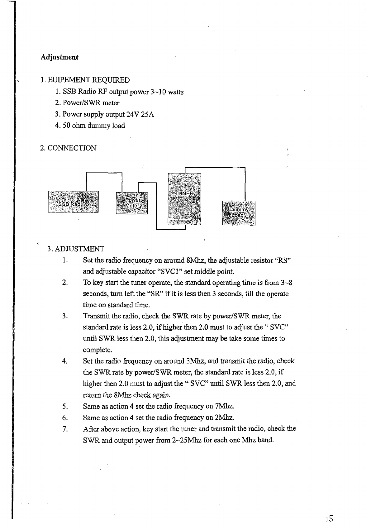
2. CONNECTION
3. ADJUSTMENT
1 . Set the radio frequency on around 8Mhz, the adjustable resistor “ RS”
and adjustable capacitor “ SVC1” set middle point.
2. To key start the tuner operate, the standard operating time is from 3-8
seconds, turn left the “ SR” if it is less then 3 seconds, till the operate
time on standard time.
3. Transmit the radio, check the SWR rate by power/SWR meter, the
standard rate is less 2.0, if higher then 2.0 must to adjust the “ SVC”
until SWR less then 2.0, this adjustment may be take some times to
complete.
4. Set the radio frequency on around 3Mhz, and transmit the radio, check
the SWR rate by power/SWR meter, the standard rate is less 2.0, if
higher then 2.0 must to adjust the 66 SVC” until SWR less then 2.0, and
return the 8Mhz check again.
5. Same as action 4 set the radio frequency on 7Mhz.
6. Same as action 4 set the radio frequency on 2Mhz.
7. After above action, key start the tuner and transmit the radio, check the
SWR and output power from 2~25Mhz for each one Mhz band.
Page 3
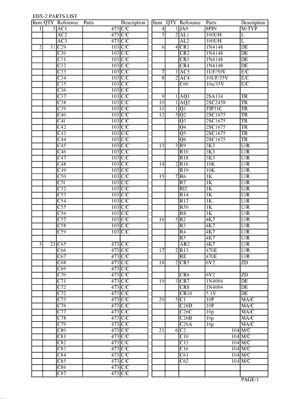
EDX-2 PARTS LIST
Item QTY Reference Parts
1 3
2 31 C29 103
3 23 C65 473
AC1
AC2 473
AC3 473
C30 103
C31 103
C32 103
C33 103
C34 103
C35 103
C36 103
C37 103
C38 103
C39 103
C40 103
C4l 103
C42 103
C43 103
C44 103
C45 103
C46 103
C47 103
C48 103
C49 103
C50 103
C5l 103
C52 103
C53 103
C54 103
C55 103
C56 103
C57 103
C58 103
C59 103
C66 473
C67 473
C68 473
C69 473
C70 473
C71 473
C72 473
C72 473
C73 473
C76 473
C77 473
C78 473
C79 473
C80 473
C81 473
C82 473
C83 473
C84 473
C85 473
C86 473
C87 473
Description
473
C/C
C/C
C/C
C/C
C/C
C/C
C/C
C/C
C/C
C/C
C/C
C/C
C/C
C/C
C/C
C/C
C/C
C/C
C/C
C/C
C/C
C/C
C/C
C/C
C/C
C/C
C/C
C/C
C/C
C/C
C/C
C/C
C/C
C/C
C/C
C/C
C/C
C/C
C/C
C/C
C/C
C/C
C/C
C/C
C/C
C/C
C/C
C/C
C/C
C/C
C/C
C/C
C/C
C/C
C/C
C/C
Item QTY Reference Parts Description
4 1 JA9
5 2 AL1 100UH L
AL2 100UH L
6 4 CR1 1N4148 DE
CR2 1N4148 DE
CR3 1N4148 DE
CR4 1N4148 DE
7 1 AC5 1UF/50V
8 2 AC4 10UF/35V
C60
9 1 AQ1 2SA134 TR
10 1 AQ2 2SC2458 TR
11 1 Q1
12 5 Q2 2SC1675 TR
Q3 2SC1675 TR
Q4
Q5 2SC1675 TR
Q6 2SC1675 TR
13 3 R9 3K3
R10 3K3
R18 3K3
14 2 R16 10K
R19 10K
15 7 R6 1K
R7 1K
Rl2 1K
R14 1K
R17 1K
R50 1K
RS
16 5 R2 4K7
R3 4K7
R4 4K7
R5 4K7
AR2 4K7
17 2 R13 470E
RE 470E
18 2 CR5 6V2 ZD
CR6 6V2 ZD
19 3 CR7 1N4004 DE
CR8 1N4004 DE
CR10
20 5
21 6
C1
C26D 10P
C26C 10p
C26B 10p
C26A 10p
C2
C10 104
C13 104
C16 104
C61 104
C62 104
8PIN
10u/35V E/C
TIP31C
2SC1675 TR
1K
5.1V
10P
104
M-TYP
E/C
E/C
TR
U/R
U/R
U/R
U/R
U/R
U/R
U/R
U/R
U/R
U/R
U/R
U/R
U/R
U/R
U/R
U/R
U/R
U/R
U/R
DE
MA/C
MA/C
MA/C
MA/C
MA/C
M/C
M/C
M/C
M/C
M/C
M/C
PAGE-1
Page 4
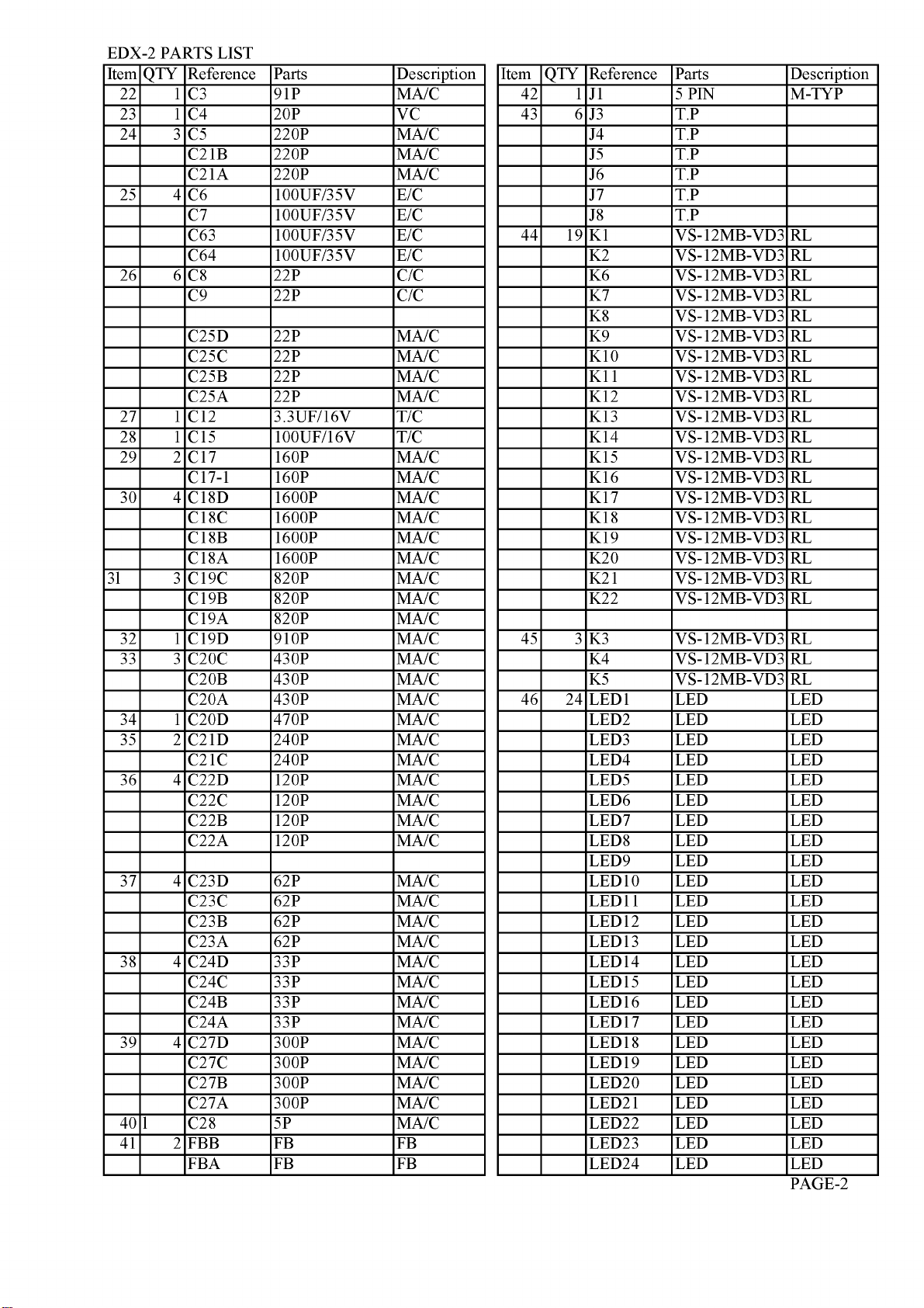
EDX-2 PARTS LIST
QTY Reference
Item
22 1
23 1
24 3
25 4
26 6
27 1 C12
28 1 C15
29 2 C17 160P MA/C
30 4 C18D 1600P MA/C
3l 3
32 1 C19D 910P MA/C
33 3 C20C 430P MA/C
34 1 C20D 470P MA/C
35 2 C21D 240P MA/C
36 4 C22D 120P MA/C
37 4 C23D 62P MA/C
38 4 C24D 33P MA/C
39 4 C27D 300P MA/C
40 l C28 5P MA/C
41 2 FBB FB FB
C3
C4
C5
C21B 220P MA/C
C21A 220P MA/C
C6 100UF/35V E/C
C7 100UF/35V E/C
C63
C64
C8
C9
C25D 22P MA/C
C25C
C25B 22P MA/C
C25A 22P MA/C
C17-1 160P MA/C
C18C
C18B 1600P MA/C
C18A 1600P MA/C
C19C
C19B 820P MA/C
C19A 820P
C20B 430P MA/C
C20A 430P MA/C
C21C
C22C 120P MA/C
C22B 120P MA/C
C22A 120P MA/C
C23C
C23B 62P MA/C
C23A 62P MA/C
C24C 33P MA/C
C24B 33P MA/C
C24A 33P MA/C
C27C 300P MA/C
C27B 300P MA/C
C27A 300P MA/C
FBA FB FB
Parts Description
91P
20P
220P MA/C
100UF/35V E/C
100UF/35V E/C
22P
22P
22P MA/C
3.3UF/16V T/C
100UF/16V T/C
1600P MA/C
820P MA/C
240P MA/C
62P MA/C
MA/C
VC
C/C
C/C
MA/C
QTY Reference
Item
42 1
43 6 J3 T.P
44 19 K1 VS-12MB-VD3 RL
45 3 K3 VS-12MB-VD3 RL
46 24 LED1 LED LED
J1 5 PIN
J4 T.P
J5 T.P
J6 T.P
J7 T.P
J8 T.P
K2 VS-12MB-VD3 RL
K6 VS-12MB-VD3 RL
K7 VS-12MB-VD3 RL
K8 VS-12MB-VD3 RL
K9 VS-12MB-VD3 RL
K10 VS-12MB-VD3 RL
K11 VS-12MB-VD3 RL
K12 VS-12MB-VD3 RL
K13 VS-12MB-VD3 RL
K14 VS-12MB-VD3 RL
K15 VS-12MB-VD3 RL
K16 VS-12MB-VD3 RL
K17 VS-12MB-VD3 RL
K18 VS-12MB-VD3 RL
K19 VS-12MB-VD3 RL
K20 VS-12MB-VD3 RL
K21 VS-12MB-VD3 RL
K22 VS-12MB-VD3 RL
K4 VS-12MB-VD3 RL
K5 VS-12MB-VD3 RL
LED2 LED LED
LED3 LED LED
LED4 LED LED
LED5 LED LED
LED6 LED LED
LED7 LED LED
LED8 LED LED
LED9 LED LED
LED10 LED LED
LED11 LED LED
LED12 LED LED
LED13 LED LED
LED14 LED LED
LED15 LED LED
LED16 LED LED
LED17 LED LED
LED18 LED LED
LED19 LED LED
LED20 LED LED
LED21 LED LED
LED22 LED LED
LED23 LED LED
LED24 LED LED
Parts
Description
M-TYP
PAGE-2
Page 5

EDX-2 PARTS LIST
QTY Reference
Item
47 1 L1 46T T
48 2 L3 17T T
L13 17T T
49 1 L2 34T T
50 1 L4 13T T
51 1 L5 8T T
52 1 L6 11T T
53 1 L7 7T T
54 1 L8 6T T
55 1 L9 4T T
56 1 L10 3T T
57 1 L11 2T T
58 1 L12 1MH T
59 1 L13 14T T
60 1 L14 15T T
61 1 L16 FBX3 FB
62 1 M-KIT RF IN M-TYP
63 1 ANT
64 2 R1 56E
R47 56E
65 1 R15 22K
66 3 R20 680E
R22 680E
R23 680E
67 23 R24 2K2 F/R
R25 2K2 F/R
R26 2K2 F/R
R27 2K2 F/R
R28 2K2 F/R
R29 2K2 F/R
R30 2K2 F/R
R31 2K2 F/R
R32 2K2 F/R
R33 2K2
R34 2K2
R35 2K2
R36 2K2
R37 2K2
R38 2K2
R39 2K2
R40 2K2
R4l 2K2
R42 2K2
R43 2K2
R44 2K2
R45 2K2
R46 2K2
68 1 R48 100E 1E
69 1 R49 100E
70 1 5T 2.1 T
71 1
72 3 U2 TD62003AP
73 1 U5 HD6305V0P
74 1 X.L1 2.99MHZ XL
U1
U3 TD62003AP
U4 TD62003AP
Parts Description
U/R
U/R
U/R
U/R
U/R
U/R
U/R
U/R
U/R
U/R
U/R
U/R
U/R
U/R
U/R
U/R
U/R
U/R
U/R
U/R
U/R
U/R
HA17458
IC
IC
IC
IC
IC
QTY Reference
Item
Parts Description
10
10 NUT M4
SCREW 4+15
Page 6

BALINGO
E D X - 2 AUTOMATIC ANTENNA TUNER
Alinco’s EDX-2 is an autom atic antenna tuner that matches your transceiver to an
antenna of over 3 meters in length ( 3.5MHz and above ), or over 12 meters in
length ( 1.6MHz and above ). This manual contains information you should know
before installing the ED X-2 and describes how to set up, connect, and operate.
SPECIFICATIONS
Frequency Range
Input power (MAX)
Input impedance
Tuning Voltage
3.5 - 30M Hz( with over 3 meter e lem en t)
1.6 - 30M Hz( with over 12 meter e lem e n t)
200W P.E.P.
50 Q
13.8V DC ± 10%
ENCLOSURE
The following items are enclosed in the package of the EDX-2:
(1) EDX-2 itself
(2) U-bolts, 2 pcs.
(3) U- bolt plates, 2 pcs.
(4) Flat washers ( large ), 8 pcs.
(5) Flat washers ( sm all), 4 pcs.
(6) Spring washers, 8 pcs.
(7) Nuts, 8 pcs.
(8) Hex bolts, 4 pcs.
(9) Self-tapping screws, 4 pcs.
(10) Rubber cap, 1 pc.
CAUTION !
• DO NOT use this tuner when it is not grounded. You must ground the
tuner through the ground terminal before operating. DO Not use the
mounting plates for grounding ; the ground-terminal should be
grounded independently.
• DO NOT use gas pipes for grounding.
• DO NOT transmit or tune without an antenna.
• DO NOT touch the antenna, ground wire, or come close to the
antenna element while transmitting or tuning. Place the EDX -2 and
antenna in a position where you are sure it will not be touched.
Page 7

INSTALLATION
(1) Mount the EDX-2 to the desired position.(Figs. 2 & 3)
(2) Ground the EDX-2 grounding-terminal through an independent wire as short as possible.
(3) Connect an antenna element *to EDX-2’s antenna element terminal.(Fig.l)
(4) Connect the EDX-2’s control cable to your radio’s accessory terminal.(Fig. 1)
(5) Connect the EDX-2’s co-ax cable to your radio’s antenna terminal.(Fig.1
You may extend the control and co-ax cables to the desired length, (co-ax impedance is 50 Q .)
*Avoid undesirable antenna length(See p.3)
F i g . 2 M O U N T I N G T H E E D X - 2
MOUNTING
ON A POLE
U-bolts
Using h e x -he a d
Sprin g w a s he r
Fla t w a s her
Using h e x-h e a d
MOUNTING
ON A FLAT SURFACE
2
Page 8

F i g . 1 C A B L E C O N N E C T I O N S
C o m a l c ib la
D X - 7 0 / D X - 7 0 1
1 3 F “ ar
(W H tT £ ) 2
(«**) - X
C&Lk)
----
Ground
7 ♦ 13. 8V DC
CpED)
Note:Do not open the BDX-2 cabinet unless necessary.
WEH333W
Top Cov«r
t
-------------------------\
o
s
» .
ÍI-S E /
CtRnew /
B o tto m
C o v t r
R u b b a r C s ?
G rou n d
w ir«
<?R>
JTTtnot uMd)
-K*V
“S t a r t
1 4 r~ H D
C o n trol c a b i«
ERRA TA SHBBT
?l«A.«€.reT€r liiîs ~f tr cor rect u)',re.
* l l w . u k y e n A .
Page 9

OPERATION
r
V
de-do
MEMO 1 D
i ,
— TUNE —
AQC-S L C,g
incnn
f . u 3 u.u
■mi
appears while tuning
•H M M
(1) Set the desired band and frequency of the
transceiver.
(2) Push the TUNE switch on the transceiver*
• "TUNE” appears in the LCD while tuning.
• Do not change the frequency or mode while
J
tuning.
(3) After tuning is completed TUNE” disappears.
• Normally, tuning requires less than 20 secs;
average tuning time is 4-6 secs.
* F o r D X - 7 0 p r e s s F U N C th e n T U N E .
■ C A L C U L A T I O N O F U N D E S I R A B L E A N T E N N A L E N G T H
Certain lengths of antenna element could be extremely difficult to tune with EDX-2,besides causing
high-voltage on the radio chassis. Such lengths are dependent on your operating frequency, and can be
calculated as follows.
Length of 1
half-wave (1/2 A )=
----------------- --------------------
x
-----
x n
and its multiples Operating frequency (MHz) 2
Where n is an integer.
[EXAMPLE] Undesirable antenna length with an operating frequency of 29.00MHz
Multiple _ 300 x _1_ x (i 2,3,41...)=5.2>1 0.3,15.5m etc.
of 1/2 A 29 2
N O T E : This e q u ipm e n t has been te s te d an d f o u n d t o c o m p ly w ith the lim its fo r a C lass B d ig it a l d e v ice, p u rs u a n t to p a r t 15 o f th e F C C
Rule s. T hese lim its a r e d e s ign e d to p r o v id e rea s o n a b le p ro t e c tio n aga inst h a r m fu l in te rfe re n c e in a r e s id e n ti a l in s ta lla tio n . T h is e q u ip m e n t
gen e rate s , uses, a n d ca n ra d ia te r a d io fre q u e n c y e n e rg y and, i f no t in s ta lle d a n d u s e d in a c c o r d a n c e w i th th e in s tru c t io n m an u a l, m a y
cau s e h a r m fu l interfe ren c e to ra d io com m u n icatio n s.
H o w e ve r, th e r e is n o g u a r a n te e t h a t in te rfe re n c e w i l l no t o c c u r in a p a r t ic u la r in s t a l latio n . I f th is e q u ip m e n t does ca u se h a rm f u l
in terfe r e nc e t o ra d io o r t e le v ision re c e p tio n , w h ic h can be de term in e d b y t u rn in g th e e q u ip m en t o ff an d on, the us e r is e n c o u ra g e d to t r y to
c o r r e c t th e interfe re n ce b y one o r m o re o f th e f o llo w i n g m easures:
— R e o rie n t o r re loc a te the r e c e iving antenna . — Con n e c t the equip m e n t int o an outlet o n a c ircuit diffe rent
— Increas e the sep ara tion b etween the equip m e n t and fro m tha t to w h ic h the receiv e r is c onnec ted .
re c eive r. — C o n s u lt the d eale r or an experienced radio / T V te c h n ic ian for
help.
All s ta ted s pecifica tions and circ u its are subject to c h ange w ith out notice .
Names of p roducts or d e s cription s mentio n e d in th is m a n u a l are use d lo r id entification p urp o se o n ly and m a y b e tra d e mark an d /or r e siste red trademark s o f their
re spec tive com pan y .
3
Page 10

H I-
Page 11

SAUNCO
S C H E M A T I C D I A G R A M
_qK1 J
j|JvS-12TBl*-C
To "A"
ALINCO, INC.
H e a d O ffice: " T W IN 21” M ID Tower Buildin g 2 3 F
Germ any : Esch bom er Landstrasse 55 60489 Frankfurt Am Main, G ermany
1-61, 2 -Chom e, S h ir om i, C h u o -ku, O s a k a 540, Japan
Ph o n e: 0 6-9 46-8150 Fax : 06-946-8175 Telex: 63086
E -m ail: 10 1243 .1 446<g>co m puse rve.com
U.S.A.: 438 Amapola Ave., Unit 130, Torrance, CA 90501, U.S.A.
Phon e: 310-618-8616 Fax: 310-618-8758
http://www.alinco.com/
Phon e: 069-786018 Fax: 069-789-60766
i n j i n
JS1 CS2 CS3 C54 CSS CS6 CS7
10? 103 103 103 103 1 03 103
P r in t e d in J a p a n
C o p y r ig h t l 99 6 A l i n e o ,In c.
4
Page 12

Specifications subjects to change without notice
 Loading...