

Algolith XVC-1001-DC User Manual
Advanced Image Processing Solutions
HD to SD Downconverter
Installation and Operation Manual
C3033-8007-100
Copyright Algolith 2008, all rights reserved
XVC-1001-DC
Guide to installation and operation
Table of Contents
Safety ........................................... 3
Introduction ................................... 4
Overview ............................................... 4
Main Features ........................................ 4
The Algogear Series ............................... 5
Installation and setup .....................6
Static Discharge ..................................... 6
Board Installation ................................... 6
Installation and setup .....................7
Power Consumption ............................... 8
Card’s Identification ................................ 8
Rear Input / Output Module Labels .......... 9
Output Channels ................................... 10
Controls .............................................. 11
Card Info & Card Status ........................ 11
Product Status Area ............................. 11
Basic Tree View ................................... 11
Operation .................................... 11
How to Repurpose your Card ........27
Load the new product onto your card ......... 28
Technology Overview ..................33
Aspect Ratio ........................................ 33
De-Interlacing ....................................... 33
Downconverter..................................... 34
Specifi cations ..............................35
Limited Warranty .........................36
Contact us ..................................36
The Dashboard Software Interface.............. 11
The Basic Tree View Window ................. 12
The Product Status Area ....................... 12
The Card Info Window ........................... 12
The Card Status Window ....................... 12
Control ....................................................
The Card License Window ..................... 13
Control ................................................ 13
Login to administrator level ................... 14
Adjusting Parameters ................................ 14
The Administrator Level ........................ 14
Recall & apply settings ......................... 15
Save settings ....................................... 15
The Card Setup Window ....................... 15
Selecting the Reference ........................ 16
The Video Setup Window ...................... 18
Aspect Ratio Settings ........................... 20
Aspect Ratio Settings ........................... 20
Film-Based and Pixel-Based Content....... 23
The Audio Setup Window ...................... 25
The Alarm Setup Window ...................... 26
2
Guide to installation and operation
XVC-1001-DC
Safety
Before using this product, carefully review all the safety
precautions in this user guide, and all the important
regulatory and safety notices in the openGear DFR8310-C Multi-Definition Digital Products Frame User
Manual.
CAUTION
This symbol is intended to alert the
user to the presence of uninsulated
“dangerous voltage” within the product’s enclosure that may be of sufficient magnitude to constitute a risk of
electric shock to persons.
This symbol is intended to alert the
user to the presence of important
operating and maintenance (servicing) instructions in the literature
accompanying the appliance.
Restrictions on Hazardous Substances
Directive 2002/95/EC—commonly known as
the European Union (EU) Restriction on Hazardous
Substances (RoHS)—sets limits on the use of certain
substances found in electrical and electronic equipment. The intent of this legislation is to reduce the
amount of hazardous chemicals that may leach out of
landfill sites or otherwise contaminate the environment
during end-of-life recycling. The Directive takes effect
on July 1, 2006, and it refers to the following hazardous substances:
Electromagnetic Compatibility
This equipment has been tested and found to comply with the
limits for a class A digital device, pursuant to part 15 of the FCC
Rules. These limits are designed to provide reasonable protection
against harmful interference when this equipment is operated in
a commercial environment. This equipment generates, uses and
can radiate radio frequency energy and, if not installed and used
in accordance with the instructions, may cause harmful interference to radio communications. Operation of this equipment in
a residential area is likely to cause harmful interference in which
case users will be required to correct the interference at their own
expense. Changes or modifications to this equipment not expressly
approved by Algolith Inc. could void the user’s authority to operate
this equipment.
Waste from Electrical and Electronic
Equipment (WEEE) Compliance
The European Union (EU) Directive 2002/96/EC
on Waste from Electrical and Electronic Equipment
(WEEE) deals with the collection, treatment, recovery, and recycling of electrical and electronic waste
products. The objective of the WEEE Directive is to
assign the responsibility for the disposal of associated
hazardous waste to either the producers or users of
these products. Effective August 13, 2005, producers or users will be required to recycle electrical and
electronic equipment at end of its useful life, and may
not dispose of the equipment in landfills or by using
other unapproved methods. (Some EU member states
may have different deadlines.)
Equipment that complies with the EU directive will be
marked with a WEEE-compliant emblem, as shown in
the figure below.
• Lead (Pb)
• Mercury (Hg)
• Cadmium (Cd)
• Hexavalent Chromium (Cr-V1)
• Polybrominated Biphenyls (PBB)
• Polybrominated Diphenyl Ethers (PBDE)
According to this EU Directive, this product is fully
RoHS-compliant and “lead-free.”
Please insure that this equipment is properly recycled
at its end-of-life. Algolith invites you to contact your
local or regional waste administration if you need
any information on how to dispose of this equipment
in an environmentally friendly and health conscious
manner.
3

XVC-1001-DC
Guide to installation and operation
Introduction
Overview
The Algogear™ XVC-1001-DC Downconverter provides high quality
conversion from HD (SMPTE 292M) video formats such as 720p50,
720p59.94, 1080i50, and 1080i59.94 to SD (SMPTE 259M-C) video
formats such as 480i59.94 and 576i50. It offers advanced de-interlacing
and directional content adaptive scaling for superior conversion quality.
Standard and custom aspect ratio conversion and HD to SD color space
conversion are also supported. It supports minimum or variable delay of
the video output relative to the reference input.
The XVC-1001-DC can automatically delay all 16 channels (4 groups) of
embedded audio to compensate for the video delay.
Main Features
• High quality HD to SD downconversion
• Advanced motion adaptive video de-interlacing
• Directional content adaptive scaling
• Custom and fixed aspect ratio conversion settings
• Supports minimum or variable delay of video output relative to
reference
• Support synchronous 16 channels (group 1 to 4) of 48 KHz audio
(PCM 20-bits and 24-bits)
• Demultiplexing and multiplexing of audio data
• Perfect audio/video synchronization
• SNMP Support
• Controlled by easy-to-use Dashboard software
4

Guide to installation and operation
The Algogear Series
XVC-1001-DC
Designed for openGear, Algogear is a flexible, future-proof, modular solution
that can maximize bandwidth, clean, synchronize and scale media. Algogear
delivers unparalleled value and flexibility to broadcasters leveraging the
Algogear solution, giving the ground-breaking ability to reprogram the cards
with any of the available Algogear solutions at any time, at no cost.
If you have a simple configuration that will change as your needs evolve, you
can continue to change the functionality of the Algogear cards, reconfiguring
them to meet your needs over time.
The list of Algogear applications is quickly evolving. Visit www.algolith.com
for a current list of available applications and news about products coming
soon.
Card Identification
Rear module labels and card identification labels for each Algogear
application available at the time of purchase are included with your card.
In addition, an installation CD is provided which includes the user guides
of all Algogear applications available at the time of purchase. To request
additional rear module labels, card identification labels and user guides
email us at sales@algolith.com.
See the «How to Repurpose your Algogear Card» section of this manual for
more information (page 27).
5
XVC-1001-DC
Guide to installation and operation
Installation and setup
Static Discharge
Whenever handling the XVC-1001-DC and other related equipment, please
observe all static discharge precautions as described in the following
note:
Static discharge can cause serious damage to sensitive semiconductor
devices. Avoid handling circuit boards in high static environments such
as carpeted areas, and when wearing synthetic fiber clothing. Always
exercise proper grounding precautions when working on circuit boards
and related equipment.
Board Installation
Use the following procedure to install the XVC-1001-DC in an openGear
(DFR-8310-N) distribution frame with cooling fans:
Due to power consumption and heat dissipation requirements, the XVC1001-DC must only be installed in a frame with the cooling fan option
installed.
1. Refer to the User Manual of the openGear 8300 series frame
to ensure that the frame is properly installed according to
instructions.
2. A maximum of 8 XVC-1001-DC or other Algogear cards can be
installed in the DFR-8310 series frame.
Do not populate the openGear frame with more than 8 Algogear
cards. Attempting to do so may damage the cards, the frame
or both.
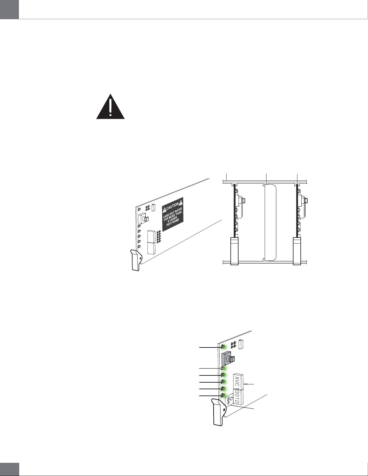
3. After selecting the desired frame and installation slot, hold the
XVC-1001-DC card by the edges and carefully align the card
edges with the slots in the frame. Then fully insert the card into
the frame until the rear connection plugs are properly seated
on the midplane and rear modules.
6
Guide to installation and operation
Installation and setup
XVC-1001-DC
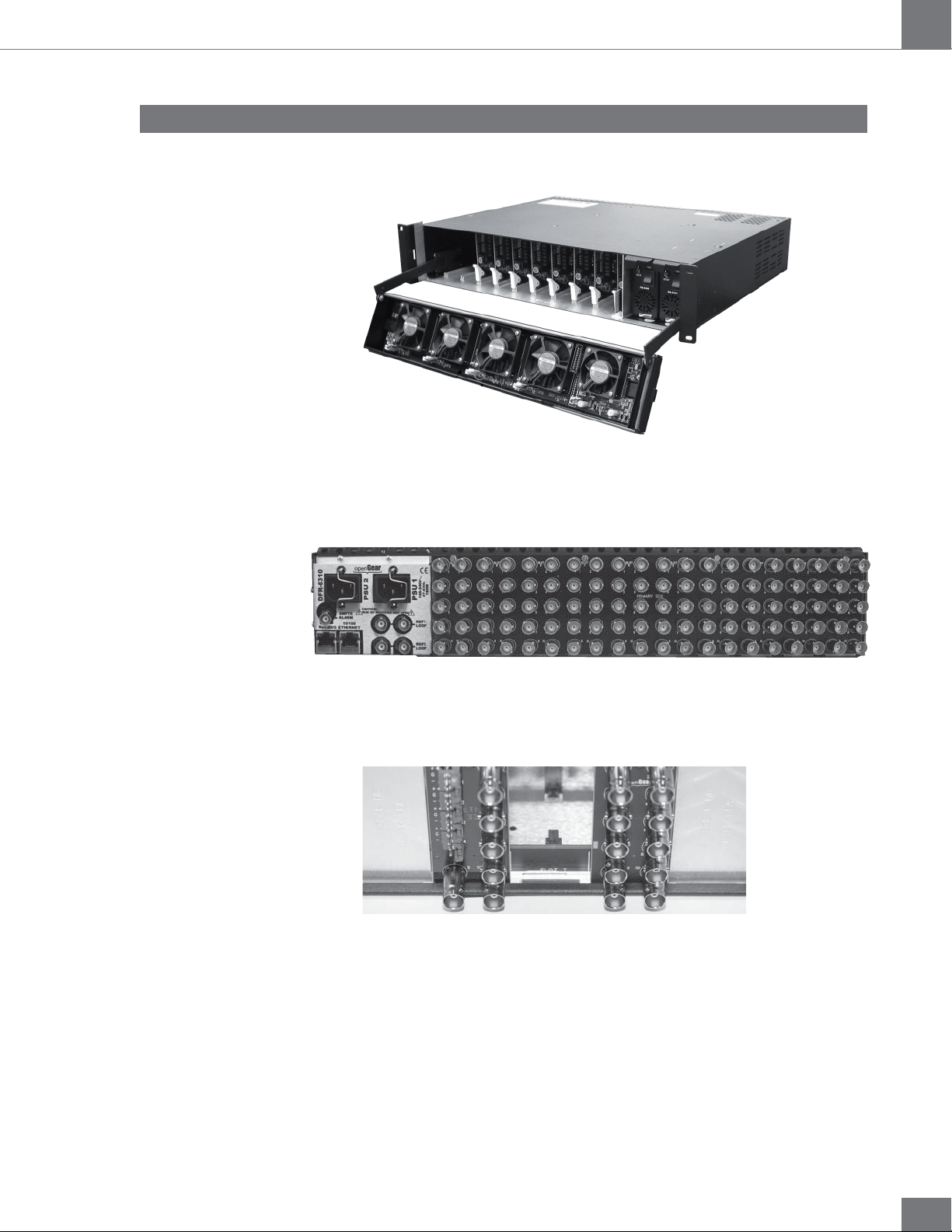
The XVC-1001-DC card is installed in the openGear frame.
openGear frame
The XVC-1001-DC card requires a BNC rear output module. Depending on the
frame model you have purchased, your frame may be equipped with a fixed
100 BNC rear panel.
openGear frame with a fixed 100 BNC rear panel
Your frame model may have a modular rear panel, to accommodate different
types of cards. You will then need to purchase and install a 10 BNC single rear
module for each XVC-1001-DC card in your openGear frame.
openGear frame with a modular rear panel
For information on the openGear frame and how to install your XVC-1001DC card and your rear modules, see the DFR-8310-C Multi Definition Digital
Products Frame and Power Supply (PS-8300) User Manual, provided with your
Algogear Installation CD.
7
XVC-1001-DC
Guide to installation and operation
Power Consumption
The power rating of the openGear frame allows 125 watts to be
redistributed over 10 slots. A single slot may exceed 12 watts but the
overall power consumption shall not be above 125 watts.
The XVC-1001-DC dissipate 14 watts.
An openGear frame, when populated with Algogear cards only
(VNR-1000-SD, VNR-1000-HD, XVC-1001-UC, FRS-1002-MD...),
shall use no more than 8 slots.
Blank slot fillers can be used to block slots in an openGear frame. Contact
Algolith if you wish to get blank slot fillers for your openGear frame. A
warning message is affixed to the XVC-1001-DC card and other Algogear
cards to ensure the user is aware of the card’s power consumption when
installing new systems, or rearranging frame configurations.
Card’s Identification
openGear frame
Blocked frame slot
XVC Cards
DO NOT REMOVE
ALGOGEAR
ALGOGEAR
The XVC-1001-DC card is identified with a product label located near
the card’s front edge. When installed in a frame and powered, the card
displays the product name on a dot matrix display. See drawing below.
ALGOGEAR
Card status (DS1)
Input 1 status (DS2)
Not used on XVC-1001-DC (DS3)
Not used on XVC-1001-DC (DS4)
Not used on XVC-1001-DC (DS5)
Card reference status (DS6)
ALGOGEAR
XVC1001D
Dot matrix display
XVC-1001-DC
Product label
8
Guide to installation and operation
Rear Input / Output Module Labels
XVC-1001-DC
6 status LEDs are located near the XVC-1001-DC card’s front edge.
Consult the graphic and color code below to identify the LEDs and their
meanings.
Card Status - LED color code
Green Yellow Red
Normal Minor Problem Critical error
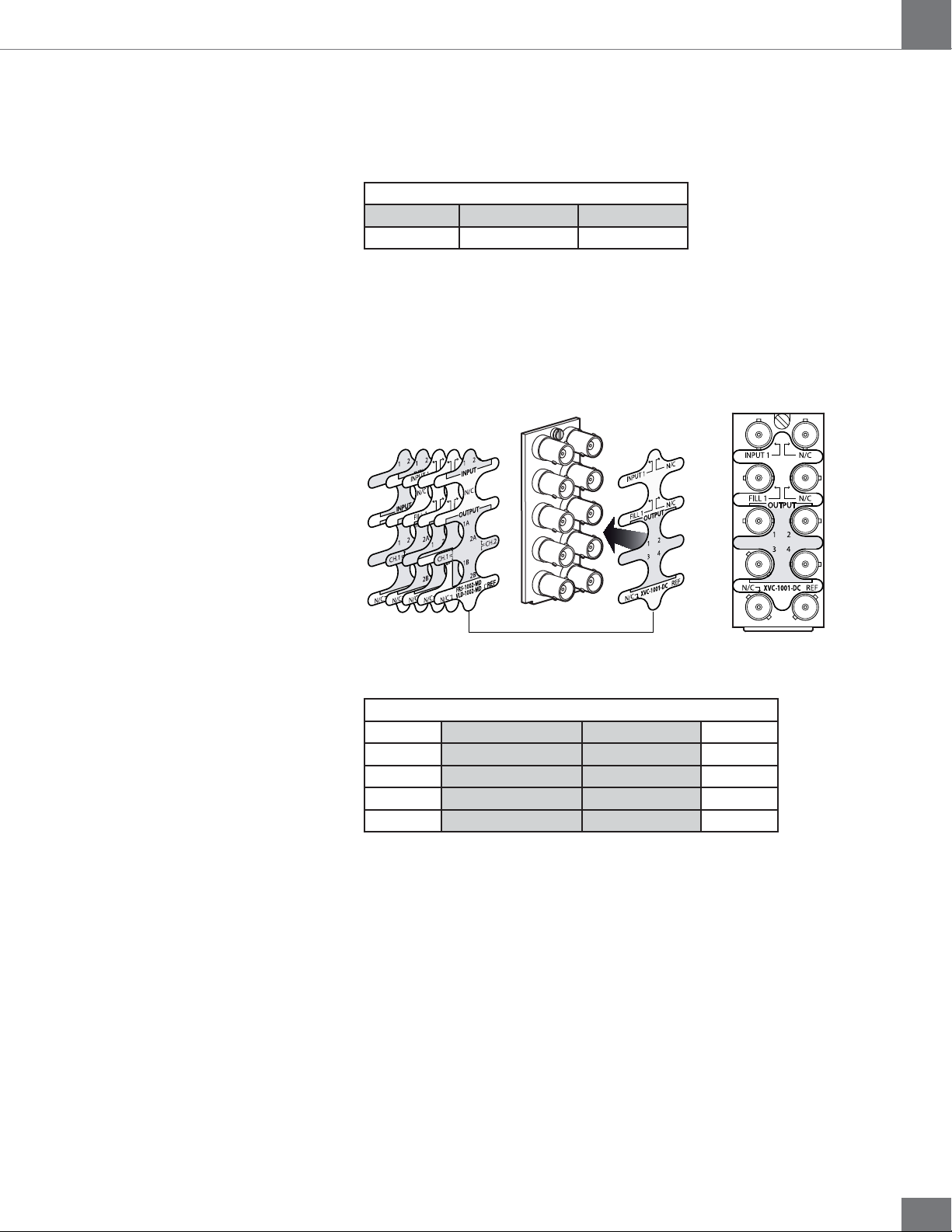
Algolith’s XVC-1001-DC card comes with the rear module labels of every
available Algogear product at the time of purchase. To identify your card
and the connectors at the back of the openGear frame, simply push the
appropriate label onto the BNC connectors to identify the card’s inputs
and outputs.
INPUT 1
34
FILL 1
1B
1A
SAFE 1
XVC-1001-UC
1C
4
3
VNR-1000-SD
Select the
appropriate label
XVC-1001-DC
BNC 1 Input 1 No Connection BNC 2
BNC 3 Bkgnd Fill (later release) No Connection BNC 4
BNC 5 Output 1 Output 2 BNC 6
BNC 7 Output 3 Output 4 BNC 8
BNC 9 No Connection Reference input BNC 10
Rear labelPush onto connectors
9
XVC-1001-DC
Output Channels
Guide to installation and operation
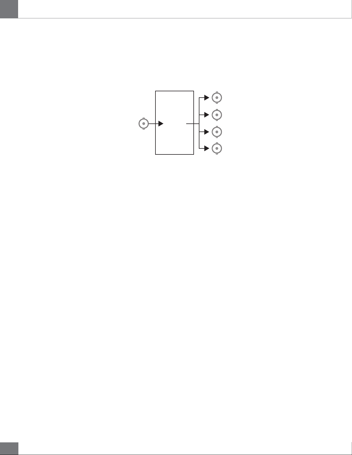
The XVC-1001-DC has 1 video input and 4 outputs. The label on the card’s
BNC rear output module, at the back of the openGear frame, identifies
the inputs and outputs.
DASHBOARD
INPUTS
1
USER INTERFACE
Channel 1
OUTPUTS
1
2
3
4
10
Guide to installation and operation
Operation
The Dashboard Software Interface
XVC-1001-DC
Once installed in the openGear frame, the XVC-1001-DC card is controlled
through the Dashboard software (version 2.2 or higher).
For information on how to install the software and to manage openGear
frames in Dashboard, please consult the Dashboard Software User
Manual, provided on the installation CD you have received with this
purchase, or visit our website at: http://www.algolith.com/support/
documentation
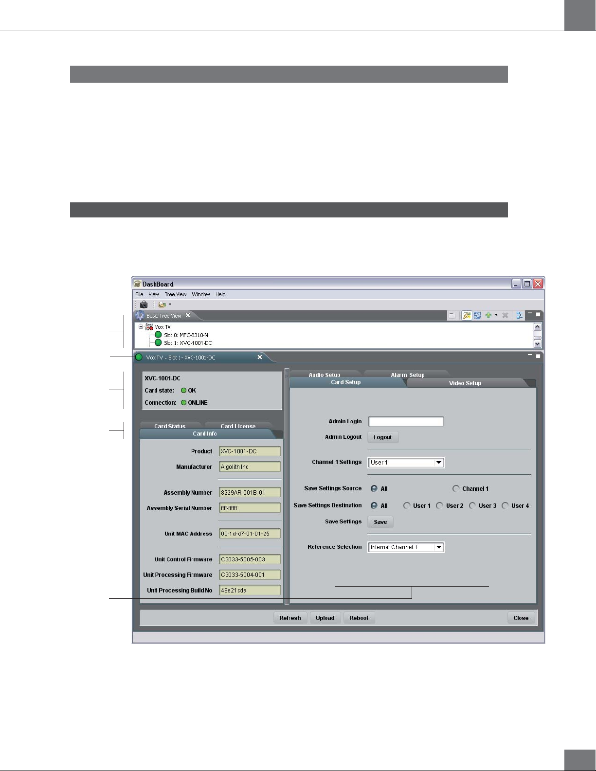
Dashboard is the openGear frame’s graphical user interface. Users
can remotely access and operate the XVC-1001-DC card through the
Dashboard software. The graphic below illustrates the basic window
structure of the interface.
Basic Tree View
Selected Frame & Card
Product Status Area
Card Info & Card Status
Controls
In Dashboard, values displayed in yellow fields cannot be modified as they
are «read only».
11
XVC-1001-DC
Guide to installation and operation
The Basic Tree View Window
All openGear frames and compatible cards in your system are displayed
in the Basic Tree View window.
Select the card you wish to control in the Basic Tree View window.
For more information on the device list please consult the Dashboard
Software User Manual.
The Product Status Area
The product status area of the Dashboard interface displays the selected
card’s product name, the card’s status (i.e. OK, Upgrade in Progress,
Alarm, or Error) and connection status (i.e. Online or Offline).
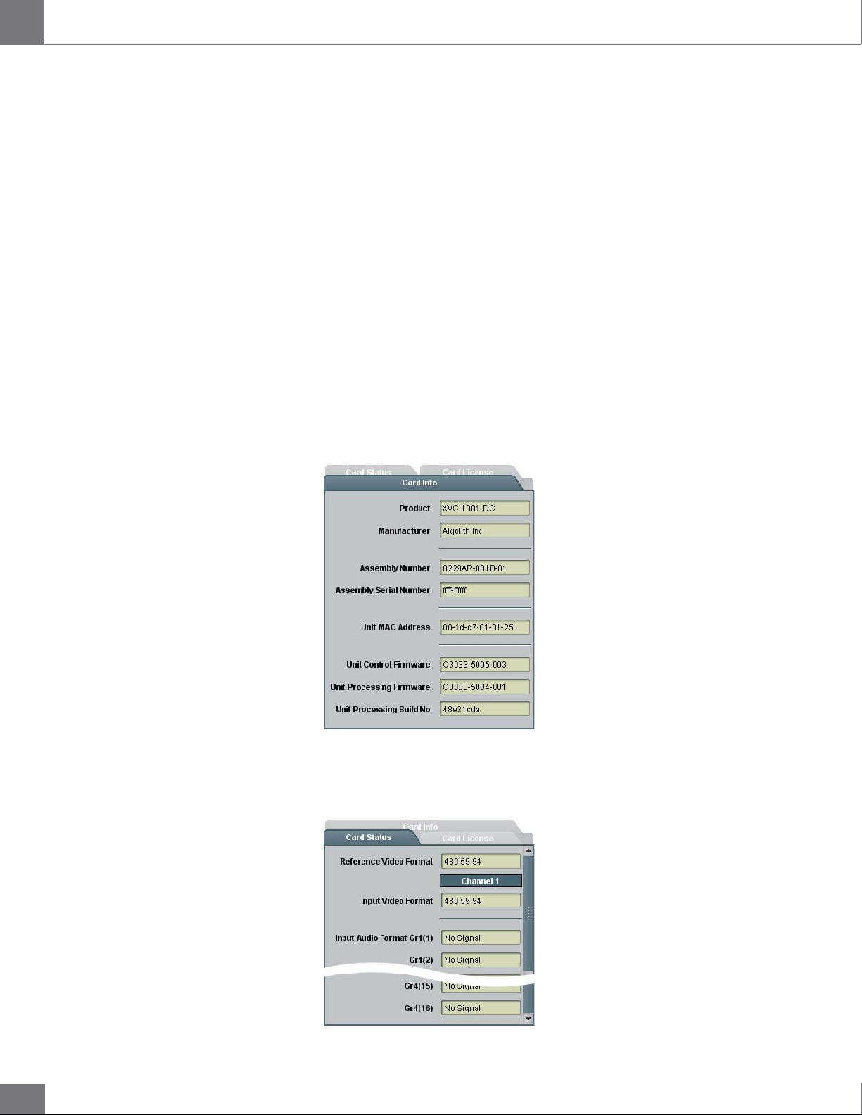
The Card Info Window
The Card Info window displays the product’s name and the manufacturer’s
name, and information that may be useful for upgrades and maintenance,
such as the assembly information, unit MAC address and firmware
information.
12
The Card Status Window
The Card Status window displays the input video format, the input audio
format, and the reference video input.
 Loading...