

Page 1
Advanced Image Processing Solutions
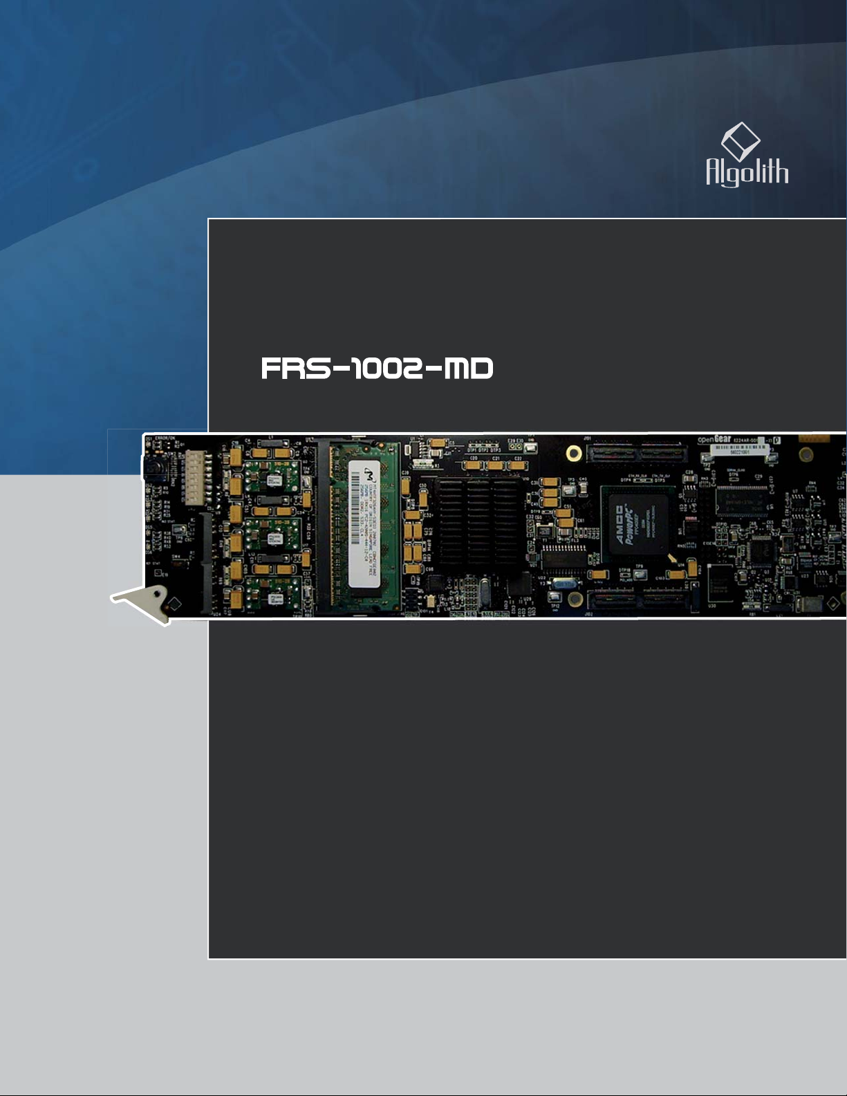
Dual SD/HD Frame Synchronizer
Installation and Operation Manual
C3032-8001-201
Copyright Algolith 2008, all rights reserved
Page 2

FRS-1002-MD / FRS-1002-MD-LG-PA
Table of Contents
Safety ........................................... 3
Introduction ................................... 4
About this manual .................................. 4
Overview ............................................... 4
Main Features ........................................ 4
Main Features ........................................ 5
Main Features ....................................... 5
The Algogear Series ............................... 6
Guide to installation and operation
Proc Amp ............................................ 21
Legalizer ............................................. 21
Audio Setup Window ............................. 22
Audio mixing Window ............................ 23
The Alarm Setup Window ...................... 26
How to Repurpose your Card ........27
Load the new product onto your card ......... 28
Installation and setup .....................7
Static Discharge ..................................... 7
Board Installation ................................... 7
Installation and setup .....................8
Power Consumption ............................... 9
Front Module .......................................... 9
Rear Input / Output Module Labels ........ 10
Output Channels ................................... 11
Controls .............................................. 12
Card Info & Card Status ........................ 12
Product Status Area ............................. 12
Operation .................................... 12
The Dashboard Software Interface.............. 12
The Basic Tree View Window ................. 13
The Product Status Area ....................... 13
The Card Info Window ........................... 13
Valid License List ................................. 13
The Card Status Window ....................... 14
Control ................................................ 14
Login to administrator level ................... 15
Adjusting Parameters ................................ 15
The Administrator Level ........................ 15
Recall & apply settings ......................... 16
Save settings ....................................... 16
The Card Setup Window ....................... 16
Selecting the Reference ........................ 17
Video Setup Window ............................. 19
Specifi cations ..............................33
Limited Warranty .........................34
Contact us ..................................34
2
Page 3
Guide to installation and operation
FRS-1002-MD / FRS-1002-MD-LG-PA
Safety
Before using this product, carefully review all the safety
precautions in this user guide, and all the important
regulatory and safety notices in the openGear DFR8310-C Multi-Definition Digital Products Frame User
Manual.
CAUTION
This symbol is intended to alert the
user to the presence of uninsulated
“dangerous voltage” within the product’s enclosure that may be of sufficient magnitude to constitute a risk of
electric shock to persons.
This symbol is intended to alert the
user to the presence of important
operating and maintenance (servicing) instructions in the literature
accompanying the appliance.
Restrictions on Hazardous Substances
Directive 2002/95/EC—commonly known as
the European Union (EU) Restriction on Hazardous
Substances (RoHS)—sets limits on the use of certain
substances found in electrical and electronic equipment. The intent of this legislation is to reduce the
amount of hazardous chemicals that may leach out of
landfill sites or otherwise contaminate the environment
during end-of-life recycling. The Directive takes effect
on July 1, 2006, and it refers to the following hazardous substances:
Electromagnetic Compatibility
This equipment has been tested and found to comply with the
limits for a class A digital device, pursuant to part 15 of the FCC
Rules. These limits are designed to provide reasonable protection
against harmful interference when this equipment is operated in
a commercial environment. This equipment generates, uses and
can radiate radio frequency energy and, if not installed and used
in accordance with the instructions, may cause harmful interference to radio communications. Operation of this equipment in
a residential area is likely to cause harmful interference in which
case users will be required to correct the interference at their own
expense. Changes or modifications to this equipment not expressly
approved by Algolith Inc. could void the user’s authority to operate
this equipment.
Waste from Electrical and Electronic
Equipment (WEEE) Compliance
The European Union (EU) Directive 2002/96/EC
on Waste from Electrical and Electronic Equipment
(WEEE) deals with the collection, treatment, recovery, and recycling of electrical and electronic waste
products. The objective of the WEEE Directive is to
assign the responsibility for the disposal of associated
hazardous waste to either the producers or users of
these products. Effective August 13, 2005, producers or users will be required to recycle electrical and
electronic equipment at end of its useful life, and may
not dispose of the equipment in landfills or by using
other unapproved methods. (Some EU member states
may have different deadlines.)
Equipment that complies with the EU directive will be
marked with a WEEE-compliant emblem, as shown in
the figure below.
• Lead (Pb)
• Mercury (Hg)
• Cadmium (Cd)
• Hexavalent Chromium (Cr-V1)
• Polybrominated Biphenyls (PBB)
• Polybrominated Diphenyl Ethers (PBDE)
According to this EU Directive, this product is fully
RoHS-compliant and “lead-free.”
Please insure that this equipment is properly recycled
at its end-of-life. Algolith invites you to contact your
local or regional waste administration if you need
any information on how to dispose of this equipment
in an environmentally friendly and health conscious
manner.
3
Page 4
FRS-1002-MD / FRS-1002-MD-LG-PA
Introduction
About this manual
Guide to installation and operation
This user guide covers both the FRS-1002-MD and FRS-1002-MD-LG-PA
cards. The FRS-1002 cards share many common features and the general
content of this user guide applies to both products. Content and features
specific to either product will be outlined by these graphic headers, so they
can be easily associated with the proper product. Enjoy your reading.
Overview
MD
The Algogear™ FRS-1002-MD Frame Synchronizer is designed to
synchronize asynchronous video feeds on a reference, in both standard
and high-definition SDI environments on up to two channels. It supports
standard definition and high-definition video formats including 1080i/60,
1080i/59.94, 1080i/50, 720p/60, 720p/59.94, 720p/50, 576i/50, and
480i/59.94.
The FRS-1002 will automatically drop or repeat video input frames to
maintain synchronization to the house sync signal. Additional delay
can also be added to the synchronizing process in pixel, line or frame
increments. Up to 11 additional frames of delay can be added in HD.
Users can also adjust embedded audio (16 channels, 4 groups) with audio
parameter controls including gain, mute and delay adjustment (up to 10
seconds). The Audio Sample Rate Converter can be disabled, or set to
automatically detect non-PCM data and disabled on a per-input basis.
Video and audio delay can be controlled independently.
LG-PA
Main Features
For added flexibility, the FRS-1002-MD-LG-PA contains a video proc amp,
allowing users to adjust video parameters such as brightness, contrast
and saturation. Hue control is available for SD standards. In addition, the
video legalizer ensures video signals conform to industry-defined «legal»
limited ranges.
• Dual channel SD/HD frame synchronizer
• Performs frame repeat or drop to align video to input reference
• Removes invalid video switching using multiple freezing modes
• Supports synchronous 16 channels (group 1 to 4) of
48 KHz audio (PCM 20-bits and 24-bits)
• Audio resampling
• Supports pass-through of non-PCM audio data
• Adjustable audio delay independent of video
• Audio mixing capabilities (level, mapping)
• SNMP Support
• Built-in audio tone generator and video test patterns
• Controlled by easy-to-use Dashboard software
4
Page 5
Guide to installation and operation
Main F
s
T
2
p
f
002
.
2
o
Demu
Genlock
F
Inp
2
Outp
O
Outp
Outp
Card Ref
F
1
Frame Ref 2
2
Audio
x
I
Audio
er
Audio
D
y
Audio
eatures
T
:
)
l
eg
r
Audio
k
2
ef
1
2
Video
s
d
r
A
o
ux
o
er
Audio
pler
o
FRS-1002-MD / FRS-1002-MD-LG-PA
MD
Main Features
eature
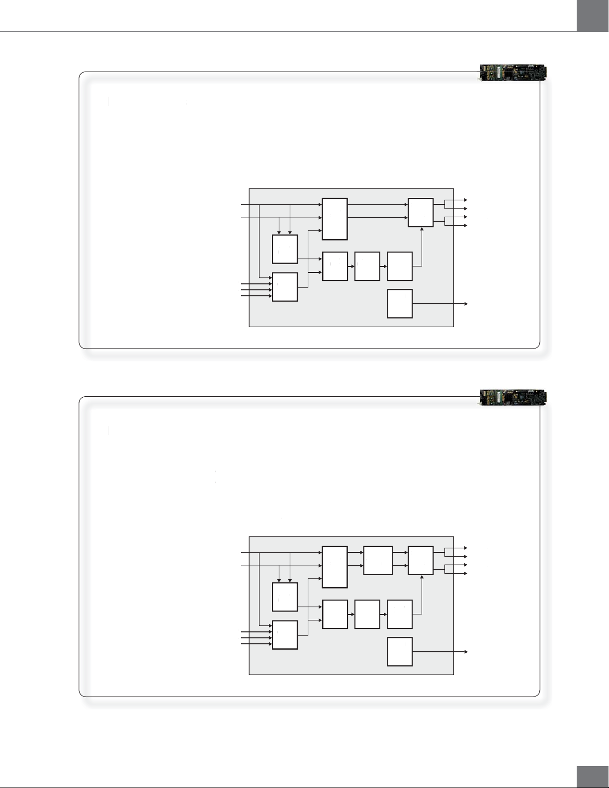
The FRS-1002-MD is a dual channel frame synchronizer. It processes
he FRS-1002-MD is a dual channel frame synchronizer. It processes
2 independent channels simultaneously in SD or HD. In addition, it
independent channels simultaneously in SD or HD. In addition, it
processes 16 channels (4 groups) of embedded audio. Video and audio
rocesses 16 channels (4 groups) of embedded audio. Video and audio
delay can be controlled independently. The graphic below represents a
delay can be controlled independently. The graphic below represents a
functional block diagram of the FRS-1002-MD.
unctional block diagram of the FRS-1
Input 1
nput 1
Input 2
Card Ref
Frame Ref 1
rame Ref
Frame Ref 2
ut
2 X 16 ch.
X 16 ch.
Audi
Audio
Demux
x
Genlock
Frame
rame
Sync
Sync
Audio
Mixer
Mix
Resampler
Resampler
Audio
-MD
Audio
Delay
Control
Control
Output 1A
2 x 16 ch.
x 16 ch.
Audio
Mu
Mux
ela
ut 1A
Output 1B
utput 1B
Output 2A
ut 2A
Output 2B
ut 2B
LG-PA
Main Features
Main F
The FRS-1002-MD-LG-PA has all the features of the FRS-1002-MD, plus:
he FRS-1002-MD-LG-PA has all the features of the FRS-1002-MD, plus
• Adjustable brightness, contrast, saturation, and hue (SD only)
Adjustable brightness, contrast, saturation, and hue (SD only
• Programmable video legalizer
Programmable video
The graphic below represents a functional block diagram of the FRS-
he graphic below represents a functional block diagram of the FRS-
1002-MD-LG-PA.
-MD-LG-PA.
Input 1
nput 1
nput
Input 2
X 16 ch.
2 X 16 ch.
Audio
Demux
emux
rd R
Card Ref
rame Ref
Frame Ref 1
rame Ref
Frame Ref 2
Genlock
enloc
alize
Frame
Frame
Sync
Sync
Audio
Audi
Mixer
x
Adjustments
Adjustment
Audio
Resampler
esam
Video
and
n
Legalizer
2 x 16 ch.
x 16 ch.
Audio
udi
Mux
Audio
Audi
Delay
elay
Control
Control
M
ize
Output 1A
utput 1B
Output 1B
utput 2A
Output 2A
utput 2B
Output 2B
t 1A
5
Page 6

FRS-1002-MD / FRS-1002-MD-LG-PA
The Algogear Series
Guide to installation and operation
Designed for openGear, Algogear is a flexible, future-proof, modular
solution that can maximize bandwidth, clean, synchronize and scale
media. Algogear delivers unparalleled value and flexibility to broadcasters
leveraging the Algogear solution, giving the ground-breaking ability to
reprogram the cards with any of the available Algogear solutions at any
time, at no cost.
If you have a simple configuration that will change as your needs evolve,
you can continue to change the functionality of the Algogear cards,
reconfiguring them to meet your needs over time.
The list of Algogear applications is quickly evolving. Visit www.algolith.
com for a current list of available applications and news about products
coming soon.
Card Identification
Rear module labels and card identification labels for each Algogear
application available at the time of purchase are included with your card.
In addition, an installation CD is provided which includes the user guides
of all Algogear applications available at the time of purchase. To request
additional rear module labels, card identification labels and user guides
email us at [email protected].
See the «How to Repurpose your Algogear Card» section of this manual
for more information (page 27).
6
Page 7

Guide to installation and operation
Installation and setup
Static Discharge
Board Installation
FRS-1002-MD / FRS-1002-MD-LG-PA
Whenever handling the FRS-1002 and other related equipment, please
observe all static discharge precautions as described in the following
note:
Static discharge can cause serious damage to sensitive semiconductor
devices. Avoid handling circuit boards in high static environments such
as carpeted areas, and when wearing synthetic fiber clothing. Always
exercise proper grounding precautions when working on circuit boards
and related equipment.
Use the following procedure to install the FRS-1002 in an openGear (DFR8310-N) distribution frame with cooling fans:
Due to power consumption and heat dissipation requirements, the
FRS-1002 must only be installed in a frame with the cooling fan option
installed.
1. Refer to the User Manual of the openGear 8300 series frame
to ensure that the frame is properly installed according to
instructions.
2. A maximum of 8 FRS-1002 or other Algogear cards can be
installed in the DFR-8310 series frame.
Do not populate the openGear frame with more than 8 Algogear
cards. Attempting to do so may damage the cards, the frame
or both.
3. After selecting the desired frame and installation slot, hold the
FRS-1002 card by the edges and carefully align the card edges
with the slots in the frame. Then fully insert the card into the
frame until the rear connection plugs are properly seated on
the midplane and rear modules.
7
Page 8
FRS-1002-MD / FRS-1002-MD-LG-PA
Installation and setup
Guide to installation and operation
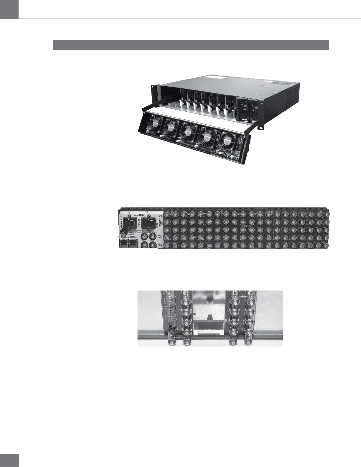
The FRS-1002 card is installed in the openGear frame.
openGear frame
The FRS-1002 card requires a BNC rear output module. Depending on the
frame model you purchased, your frame may be equipped with a fixed 100
BNC rear panel.
openGear frame with a fixed 100 BNC rear panel
Your frame model may have a modular rear panel, to accommodate different
types of cards. You will then need to purchase and install a 10 BNC single rear
module for each FRS-1002 card in your openGear frame.
openGear frame with a modular rear panel
For information on the openGear frame and how to install your FRS-1002 card
and your rear modules, see the DFR-8310-C Multi Definition Digital Products
Frame and Power Supply (PS-8300) User Manual.
8
Page 9
Guide to installation and operation
Power Consumption
FRS-1002-MD / FRS-1002-MD-LG-PA
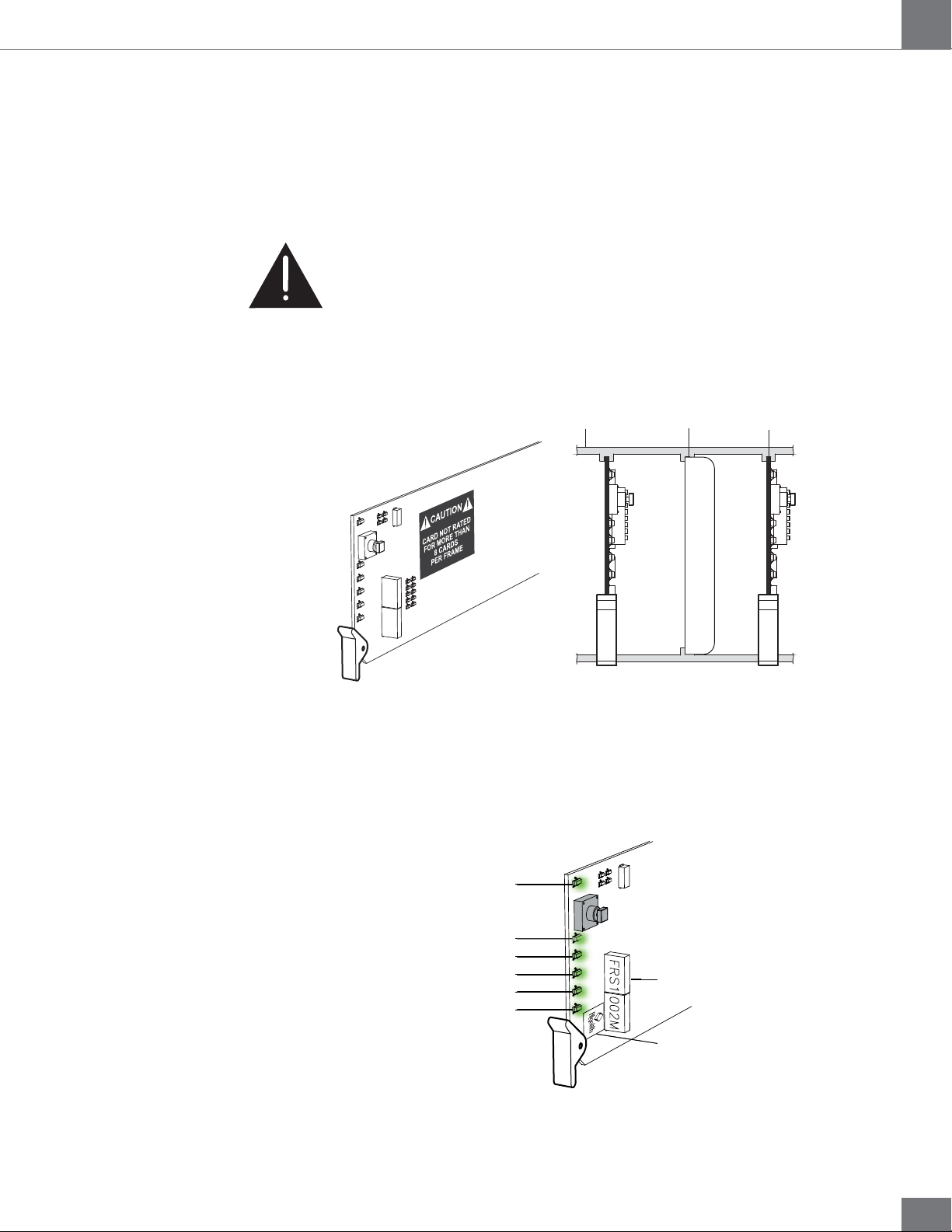
The power rating of the openGear frame allows 125 watts to be
redistributed over 10 slots. A single slot may exceed 12 watts but the
overall power consumption shall not be above 125 watts.
The FRS-1002-MD and FRS-1002-MD-LG-PA dissipate 14 watts.
An openGear frame, when populated with Algogear cards only
(VNR-1000-SD, VNR-1000-HD, XVC-1001-UC, XVC-1001-UC-BFSA, FRS-1002-MD and FRS-1002-MD-LG-PA...), shall use no more
than 8 slots.
Blank slot fillers can be used to block slots in an openGear frame. A
warning message is affixed to the FRS card and other Algogear cards to
ensure the user is aware of the card’s power consumption when installing
new systems, or rearranging frame configurations.
Front Module
openGear frame
Blocked frame slot
Algogear cards
DO NOT REMOVE
ALGOGEAR
ALGOGEAR
The FRS-1002 card is identified with a product label located near the
card’s front edge. When installed in a frame and powered, the card
displays the product name on a dot matrix display. See drawing below.
ALGOGEAR
Card status (DS1)
Input 1 status (DS2)
Input 2 status (DS3)
Not used on the FRS-1002 (DS4)
Not used on the FRS-1002 (DS5)
Card reference status (DS6)
ALGOGEAR
FRS1
Dot matrix display
002M
FRS-1002-MD
Product label
9
Page 10
FRS-1002-MD / FRS-1002-MD-LG-PA
Rear Input / Output Module Labels
Guide to installation and operation
6 status LEDs are located near the FRS-1002 card’s front edge.
Consult the graphic and color code below to identify the LEDs and their
meanings
Card Status - LED color code
Green Yellow Red
Normal Minor Problem Critical error
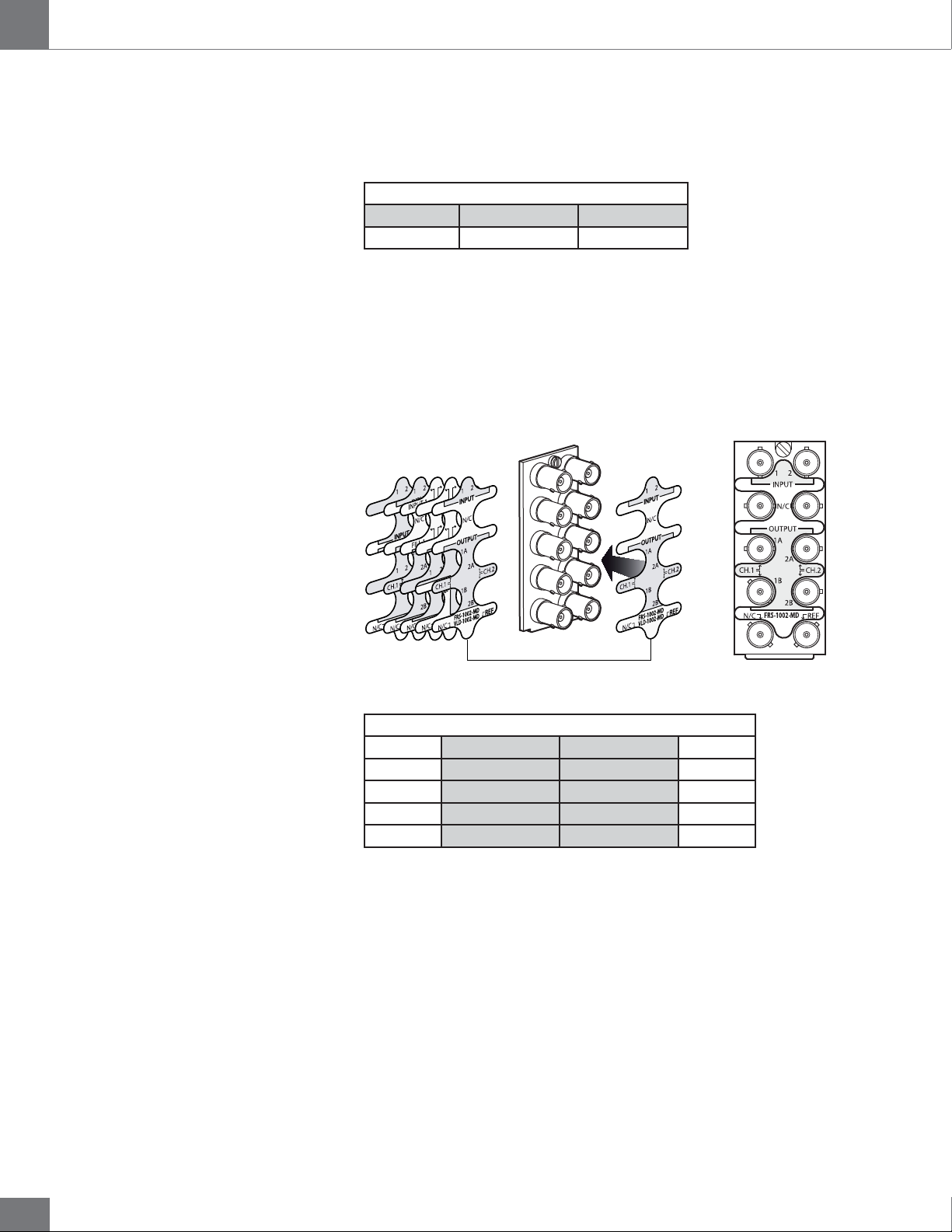
Algolith’s FRS-1002 card comes with the rear module labels of every
available Algogear product at the time of purchase. To identify your card
and the connectors at the back of the openGear frame, simply push the
appropriate label onto the BNC connectors to identify the card’s inputs
and outputs.
INPUT 1
34
FILL 1
1B
1A
1C
SAFE 1
34
VNR-1000-SD
Select the
appropriate label
XVC-1001-UC
Push onto connectors
FRS-1002-MD
BNC 1 Input 1 Input 2 BNC 2
BNC 3 No connection No connection BNC 4
BNC 5 Output 1A Output 2A BNC 6
BNC 7 Output 1B Output 2B BNC 8
BNC 9 No connection Reference BNC 10
Rear Label
10
Page 11

Guide to installation and operation
Output Channels
FRS-1002-MD / FRS-1002-MD-LG-PA
The FRS-1002 has 2 HD/SD-SDI inputs and 4 HD/SD-SDI outputs. Each
channel in the Dashboard user interface corresponds to the matching
input number. The label on the card’s BNC rear output module, at the back
of the openGear frame, identifies the inputs and outputs.
INPUTS
1
2
USER INTERFACE
Channel 1
Channel 2
OUTPUTSDASHBOARD
1A
1B
2A
2B
11
Page 12
FRS-1002-MD / FRS-1002-MD-LG-PA
Operation
The Dashboard Software Interface
Guide to installation and operation
Once installed in the openGear frame, the FRS-1002 card is controlled
through the Dashboard software (version 2.2 or higher).
For information on how to install the software and to manage openGear
frames in Dashboard, please consult the Dashboard Software User
Manual, provided on the installation CD you have received with this
purchase, or visit our website at: http://www.algolith.com/support/
documentation
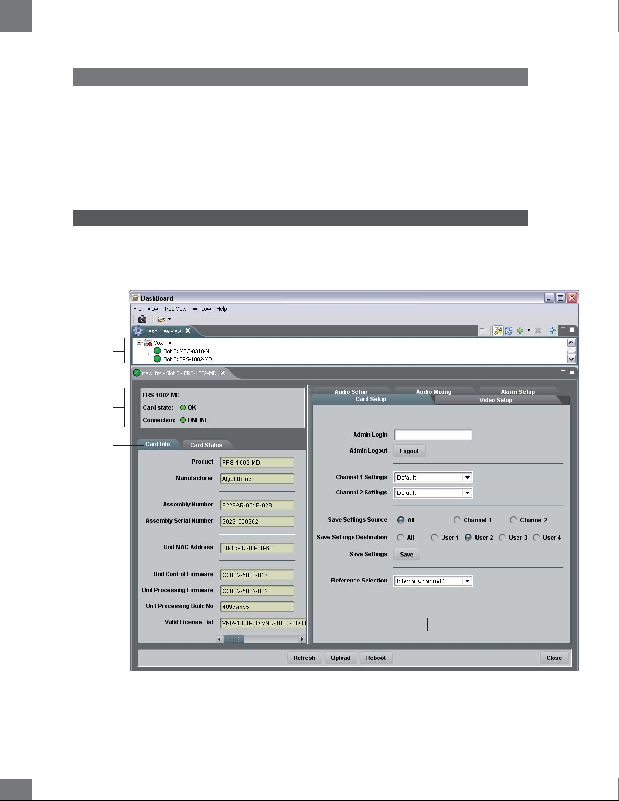
Dashboard is the openGear frame’s graphical user interface. Users can
remotely access and operate the FRS-1002 card through the Dashboard
software. The graphic below illustrates the basic window structure of the
interface.
Basic Tree View
Selected Frame & Card
Product Status Area
Card Info & Card Status
Controls
12
In Dashboard, values displayed in yellow fields cannot be modified as they
are «read only».
Page 13
Guide to installation and operation
The Basic Tree View Window
The Product Status Area
The Card Info Window
FRS-1002-MD / FRS-1002-MD-LG-PA
All openGear frames and compatible cards in your system are displayed
in the device list window.
Select the card you wish to control in the Basic Tree View tab. For more
information on the device list please consult the Dashboard Software User
Manual, provided on the installation CD.
The product status area of the Dashboard interface displays the selected
card’s product name, the card’s status (i.e. OK, Upgrade in Progress,
Alarm, or Error) and connection status (i.e. Online or Offline).
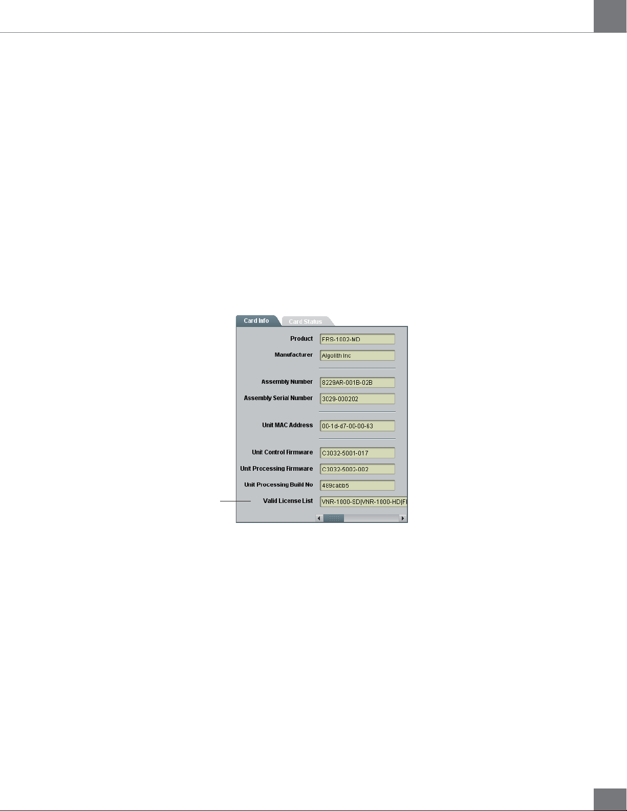
The Card Info window displays the product’s name and the manufacturer’s
name, and information that may be useful for upgrades and maintenance,
such as the assembly information, unit MAC address and firmware
information.
Valid License List
Valid License List
In order to be able to repurpose your Algogear card, a license must be
available within the card for the Algogear product you want to switch to.
The Valid License List field displays the Algogear product that were
available at the time of your purchase, and for which you have a license.
For more information on how to repurpose your Algogear card, see the
«How to Repurpose your Algogear Card» section, on page 27.
13
Page 14
FRS-1002-MD / FRS-1002-MD-LG-PA
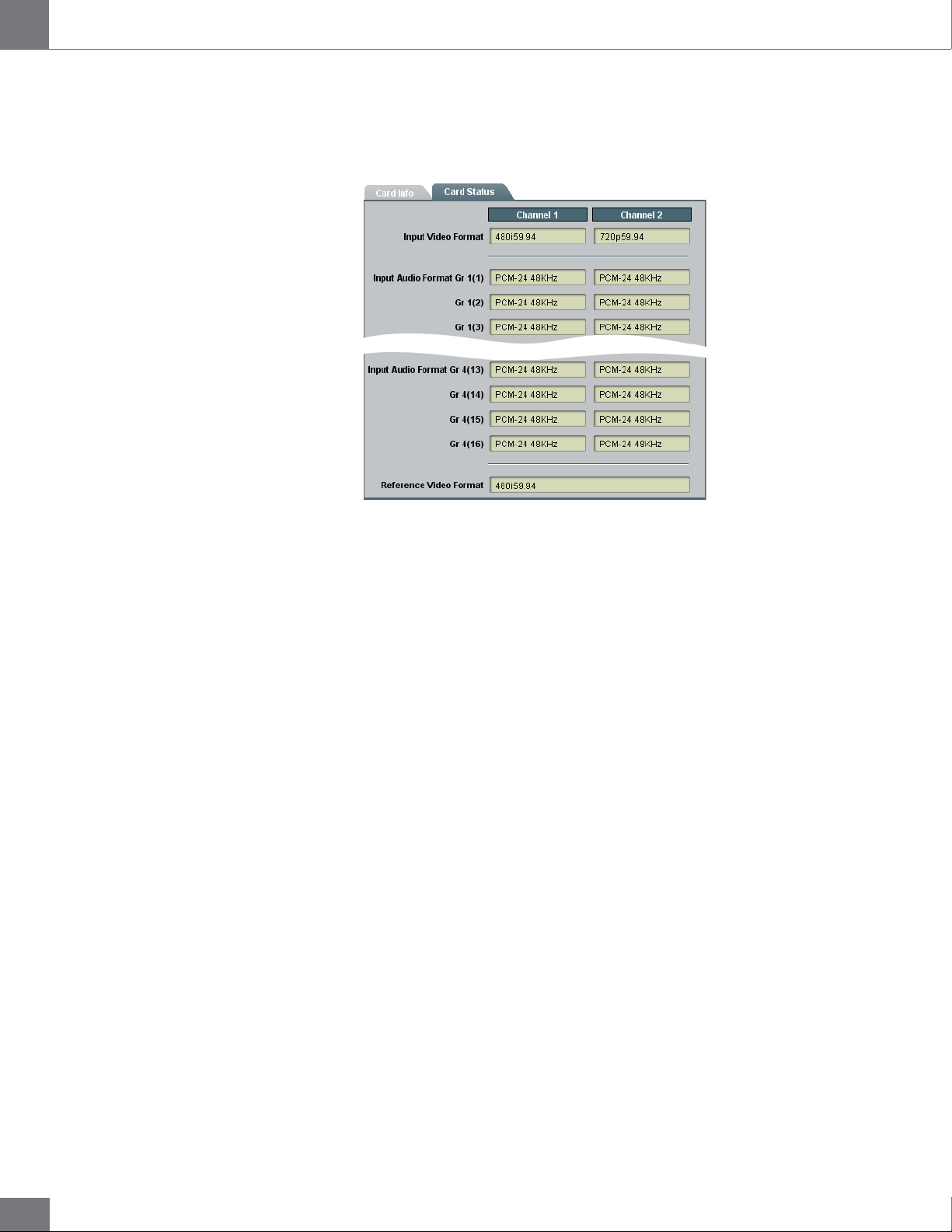
The Card Status Window
Guide to installation and operation
The Card Status window displays the input video format for each channel,
the input audio format for each channel, and the reference video input.
Control
The user can control the FRS-1002 card’s various parameters in the
Card Setup, Video Setup, Audio Setup and Alarm Setup windows.
The following section describes how to adjust the parameters.
14
Page 15
Guide to installation and operation
Adjusting Parameters
The Administrator Level
FRS-1002-MD / FRS-1002-MD-LG-PA
The FRS-1002 card provides an extra level of control and security with an
administrator password-protected level, in which the parameters of the
card can be modified and controlled. The non password-protected level
or «read only» mode, where no password is entered, allows users to view
the various settings, but does not permit changes to be made.
To protect against unwanted modification of operating parameters, the
interface provides an administrator level (password-protected) mode
which allows users the right to modify card settings.
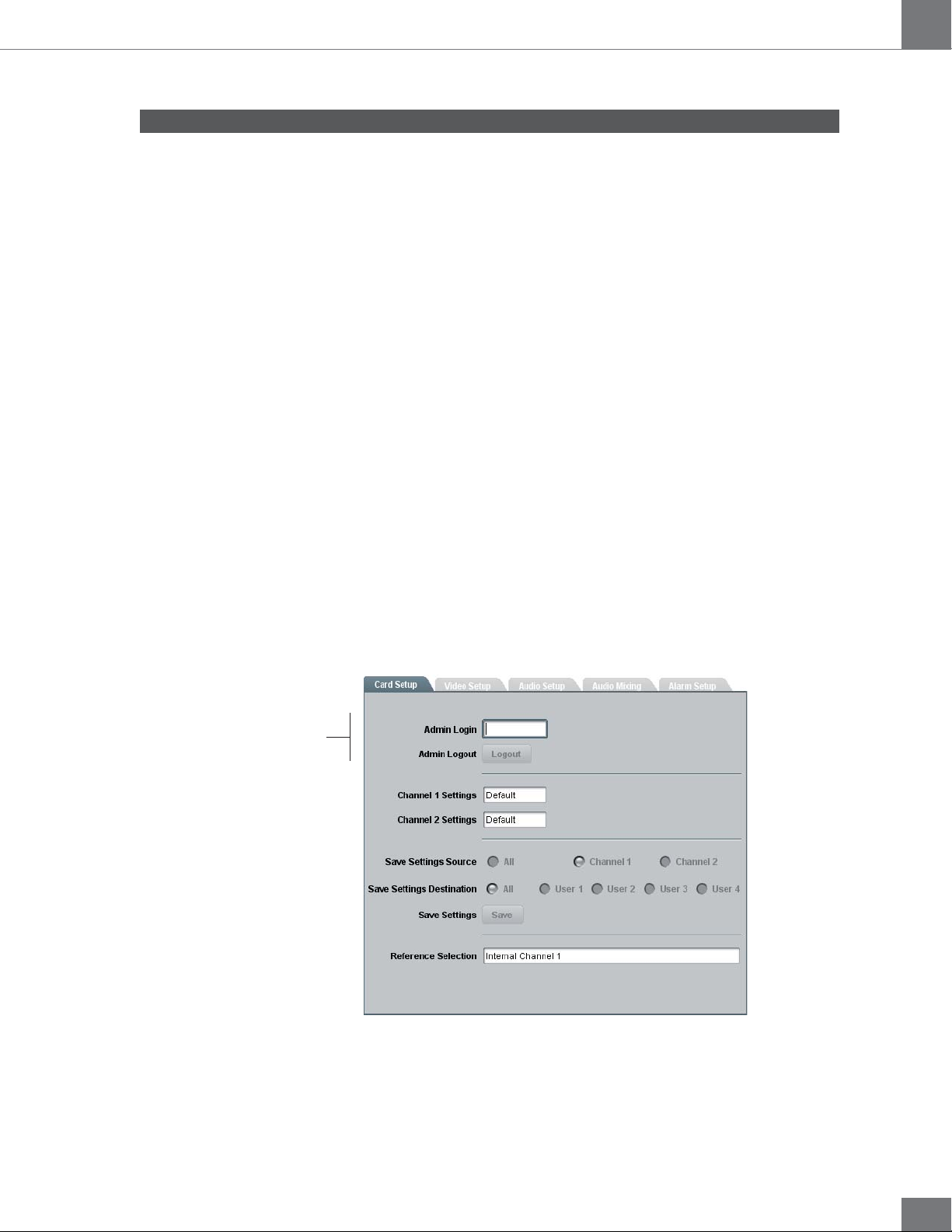
Admin Login
The Admin Login section can be found in the Card Setup window. Enter
the password «algolith» to gain full access to the administrator level.
Once the password is entered, the Card Setup window changes to
allow modification to the various settings. Allow a few seconds for the
password login to take effect.
Login to administrator level
The administrator mode remains active until you click the Logout
button.
Admin Logout
Use the Logout button to quit the administrator level. Once you have
logged out, the Card Setup window reverts back to the «read only»
mode and the preset settings cannot be modified.
Allow a few seconds for the logout to take effect.
15
Page 16
FRS-1002-MD / FRS-1002-MD-LG-PA
The Card Setup Window
Recall & apply settings
Save settings
Guide to installation and operation
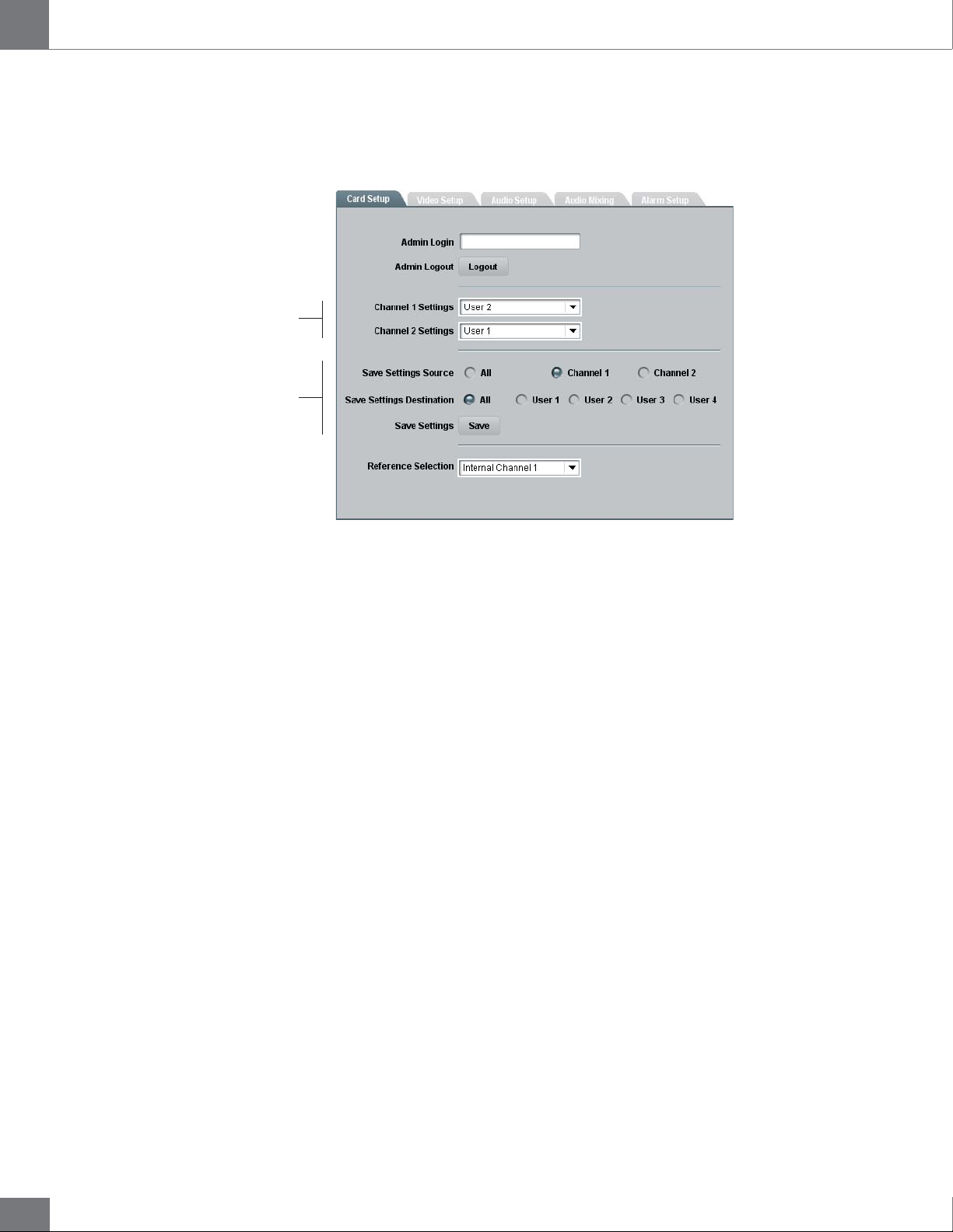
The Card Setup window allows the configuration of parameters affecting
the overall functionality of the card.
Save Settings Destination
The Save Settings Destination function allows the user to save up to
4 configurations of the FRS-1002 card’s parameters per channel. Once
you have configured the card to your liking in the Video Setup and Audio
Setup tabs of the Dashboard interface, select a name under which the
configuration will be saved, beside the Save Settings Destination
function, and hit the Save button. A dialog box will open and ask you to
confirm your decision Parameters can be saved as:
• All (applies the settings to User 1, 2, 3 and 4)
• User 1
• User 2
• User 3
• User 4
Settings can be saved by channel (1 or 2), or for both channels together
(All) in the Save Settings Source section.
Channel Settings
Once the parameters are saved to memory, the configuration becomes
available as a preset in the Channel 1 Settings or Channel 2 Settings
drop down menus.
Factory settings can be restored by selecting Default in the Channel 1
Settings or Channel 2 Settings drop down menus. The preset applies
to the selected channel only. The preset is applied immediately.
16
Following boot up of the card, the settings are automatically restored
from the channel selected settings.
Page 17
Guide to installation and operation
Selecting the Reference
FRS-1002-MD / FRS-1002-MD-LG-PA
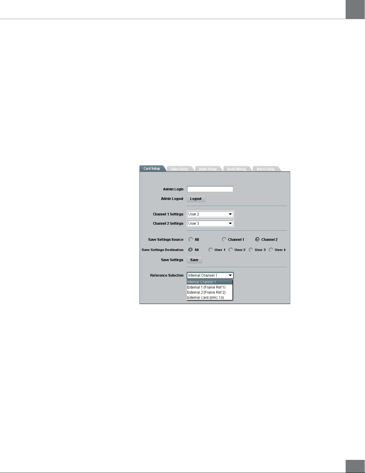
The FRS-1002 card provides four methods for referencing the incoming
video signal. At the bottom of the Card Setup window, the reference
selection can be chosen from a drop down menu. The reference selection
is automatically saved and will be restored after power-up.
The FRS-1002 accepts tri-level, bi-level and black burst reference signals.
The video inputs can be synchronized with the house sync signal.
The FRS-1002 card synchronizes the video input 1 and the video input 2
with the same reference signal. Therefore, it is mandatory for input 1 and
input 2 to be of the same video format.
Reference Selection
The Reference Selection function allows the user to select from 4
possible synchronization signals.
Select from:
Internal Ch1: Extracts the reference from the channel 1 (input 1) video
signal. With this selection, the FRS-1002 card needs a valid video signal
at input 1 to properly synchronize. If you are only connecting one video
signal to the FRS-1002 card’s rear module, use input 1.
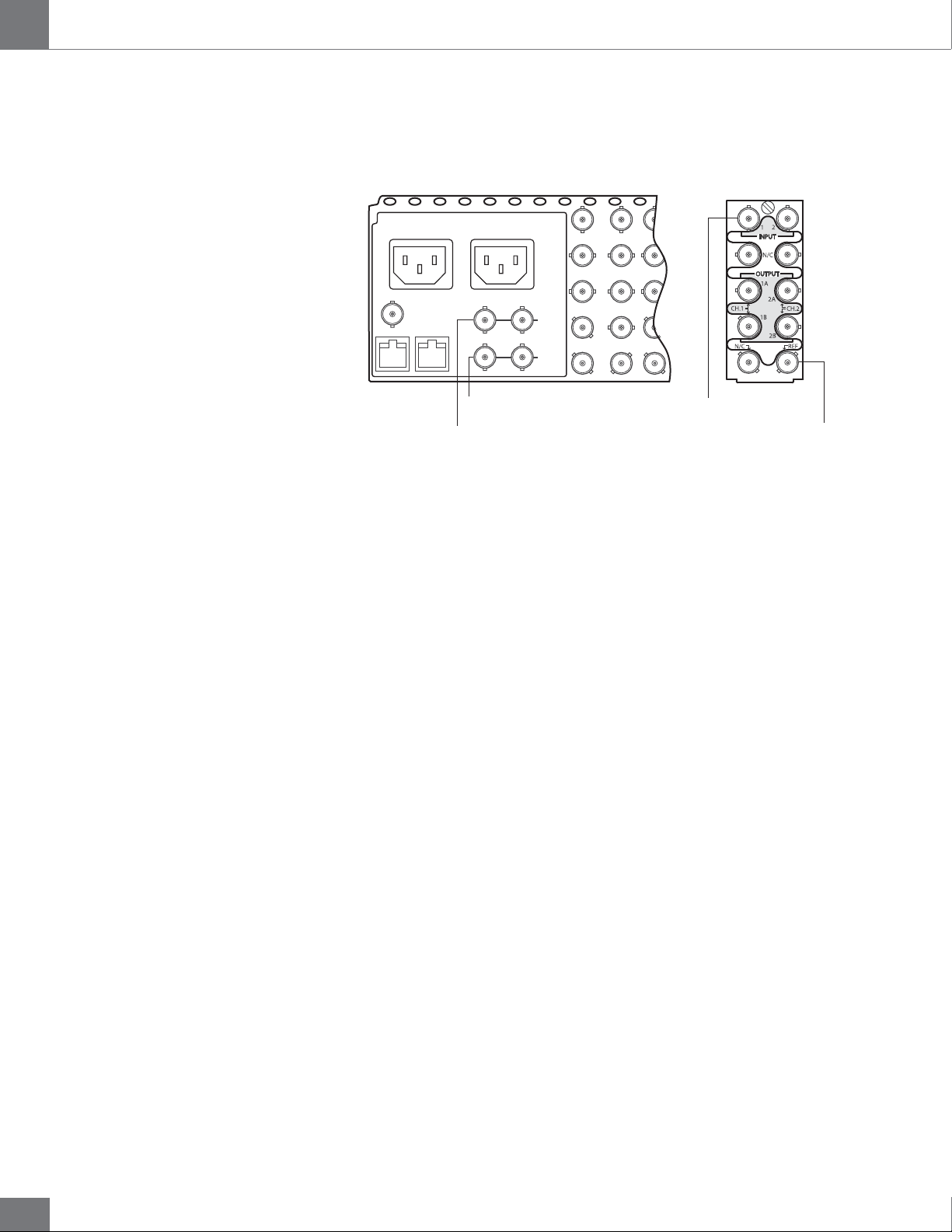
External 1 (Frame Ref 1): The openGear frame has a distributed
frame reference, allowing a single incoming reference sync signal to feed
information to all modules in a frame. External 1 uses the reference signal
from the openGear frame’s REF 1 input.
External 2 (Frame Ref 2): Uses the reference signal from the openGear
frame’s REF 2 input.
17
17
Page 18
FRS-1002-MD / FRS-1002-MD-LG-PA
Guide to installation and operation
External Card (BNC 10): Uses the reference signal from the FRS-1002
card’s rear module REF input.
DFR-8310
RossBus ETHERNET
openGear Frame
Gear
open
PSU 2
External 1 (Frame ref 1)
PSU 2
REF1
LOOP
REF2
LOOP
FRS-1002 rear module
FRS-1002-MD
Internal Ch1 (BNC 1)External 2 (Frame ref 2)
External Card (BNC 10)
18
Page 19
Guide to installation and operation
Video Setup Window
FRS-1002-MD / FRS-1002-MD-LG-PA
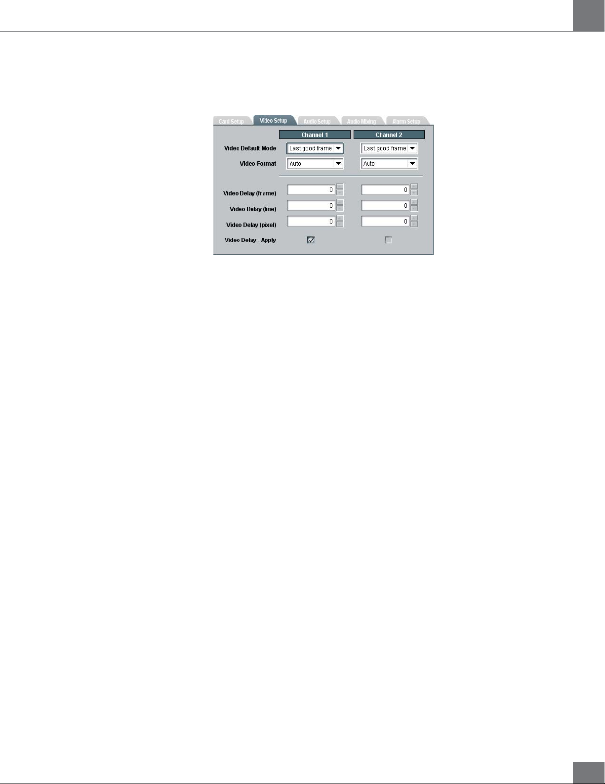
The Video Setup window allows the configuration of video parameters
affecting the individual channels of the card.
Video Default Mode
The video Default mode function is used if no valid video is detected at
the input. Also, a reference mismatch may occur if there is a difference
between the input video format’s frame rate and the reference format’s
frame rate. The FRS-1002 can be set to respond to these problems with
the Video Default Mode function. Select from:
• Last good frame (output image freezes to the last good frame)
• Last good field (output image freezes to the last good field)
• Black (a black image is generated at the output)
Video Format
The Video Format function allows the user to manually override the
detected input video format and force another format at the output. Users
may select from:
• Auto (no override)
• 480i59.94
• 576i50
• 720p50
• 720p59.94
• 720p60
• 1080i50
• 1080i59.94
• 1080i60
Video Delay (frame)
The Video Delay (frame) function allows users to adjust the delay in
increments of one full frame. Up to 11 additional frames of delay can be
added in HD.
19
Page 20
FRS-1002-MD / FRS-1002-MD-LG-PA
Guide to installation and operation
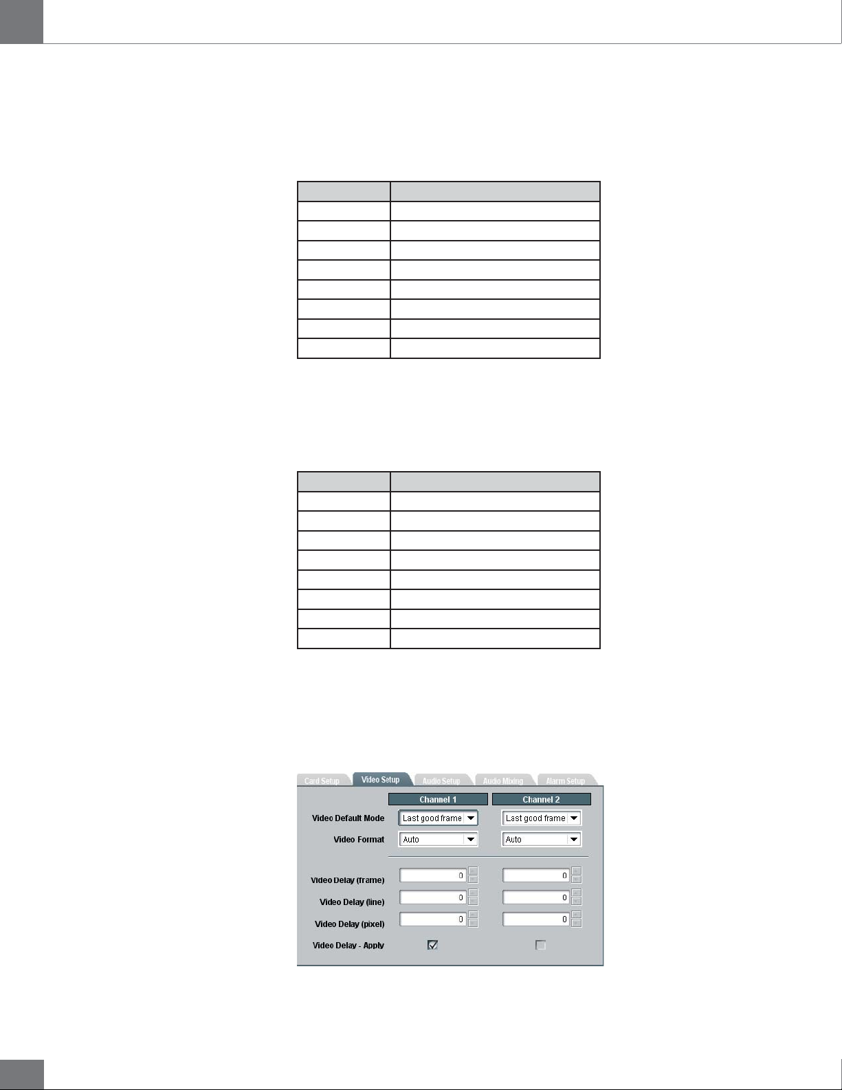
Video Delay (line)
The Video Delay (line) function allows users to adjust the delay in
increments of one line. Maximum line delay values vary depending on the
input format as follows:
Format Line Delay Range
408i59.94 0 to 524
576i50 0 to 624
720p50 0 to 749
720p59.94 0 to 749
720p60 0 to 749
1080i50 0 to 1124
1080i59.94 0 to 1124
1080i60 0 to 1124
Video Delay (pixel)
The Video Delay (pixel) function allows users to adjust the delay in
increments of one pixel. Maximum pixel delay values vary depending on
the input format as follows:
Format Pixel Delay Range
408i59.94 0 to 857
576i50 0 to 863
720p50 0 to 1979
720p59.94 0 to 1649
720p60 0 to 1649
1080i50 0 to 2639
1080i59.94 0 to 2199
1080i60 0 to 2199
Video Delay - Apply
In order for your settings to be applied, you must check the Video Delay
- Apply check box. The video delay is not automatically applied to your
input video while you are changing the values in the frame, line and pixel
fields of the dialog box.
20
Page 21
Guide to installation and operation
FRS-1002-MD / FRS-1002-MD-LG-PA
LG-PA
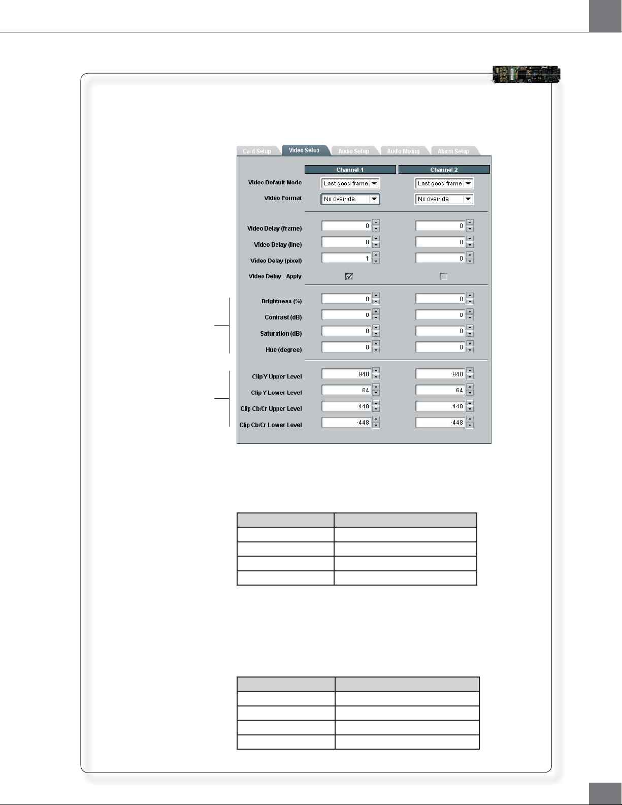
The Video Setup window for the FRS-1002-MD-LG-PA allows for
configuration of the same video parameters as the FRS-1002MD, however, additional settings are available for the card’s
Legalizer and Proc Amp.
Proc Amp
Legalizer
Proc Amp
Legalizer
The proc amp allows for adjustments to the Brightness, Contrast,
Saturation and Hue levels of the video image. These parameters
can be set as follows:
Parameters Range
Brightness -10% to 10%, in 0.5% increments
Contrast -6dB to 6dB, in 0.5dB increments
Saturation -6dB to 6dB, in 0.5dB increments
Hue -20º to 20º, in 1º increments
The FRS-1002-MD-LG-PA ensures video signals conform to
industry-defined «legal» limited ranges. The legalizer allows users
to adjust the clipping for Luminance (Y) and Chrominance (Cb/
Cr) as follows:
Parameters Range
Clip Y upper level 64 to 1019, factory setting: 940
Clip Y lower level 4 to 1019, factory setting: 64
Clip Cb/Cr upper level 0 to 511, factory setting: 448
Clip Cb/Cr lower level -512 to -1, factory setting: -448
21
Page 22
FRS-1002-MD / FRS-1002-MD-LG-PA
Audio Setup Window
Guide to installation and operation
The FRS-1002 card supports 16 audio channels in 4 groups of PCM-20
bits and PCM-24 bits encoded audio at 48KHz.
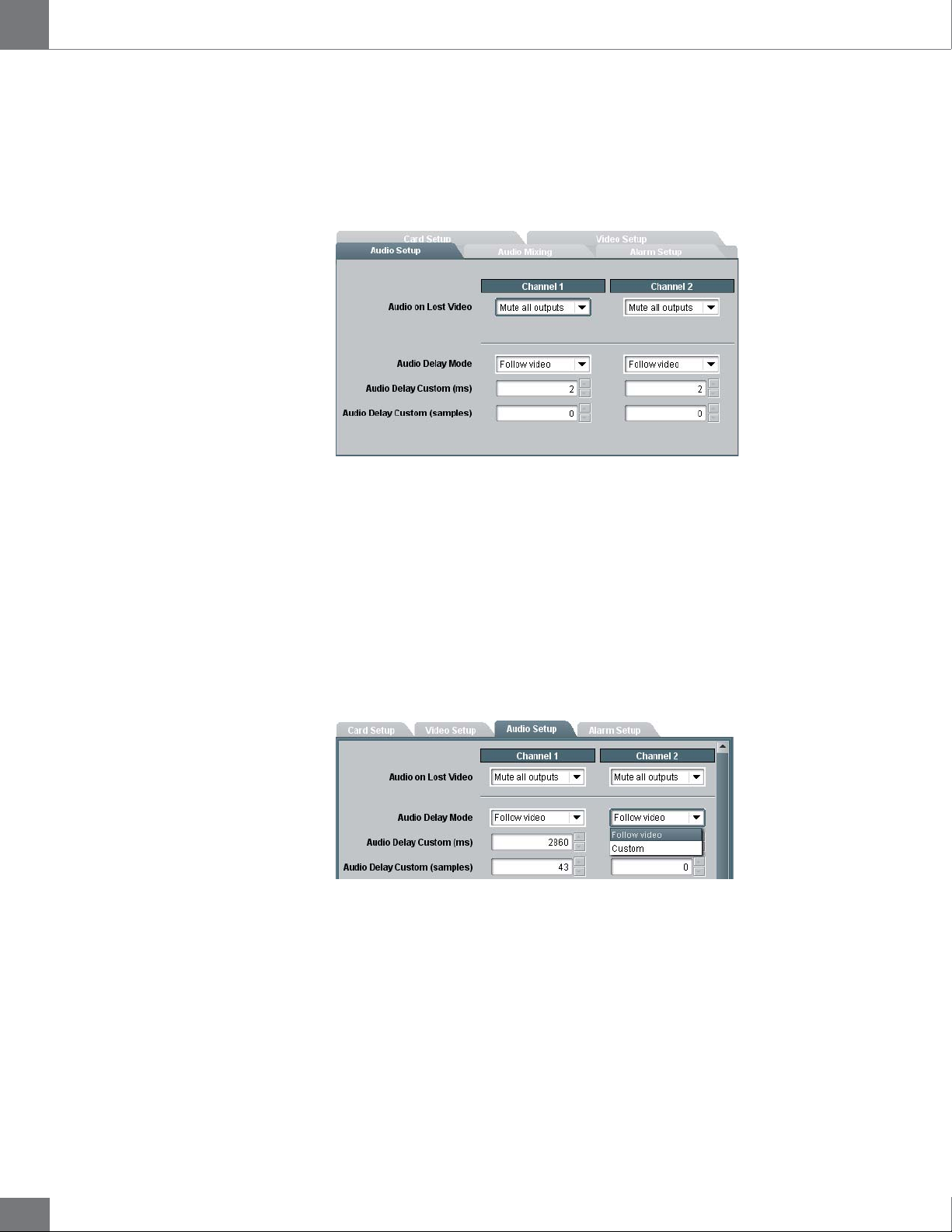
The Audio Setup window allows the configuration of audio parameters
(16 channels, 4 groups) affecting the individual channels of the card.
Audio on Lost Video
When the video input is lost or when a signal reference mismatch occurs
the FRS-1002 responds with an action set by the user in the Video Default
Mode function for video, and in the Audio on Lost Video function for
audio. The audio data can be muted to prevent undesirable noise at the
output, or a standard audio 1 KHz test tone can be inserted.
In the Mapping tab, select the Audio on Lost Video to choose from:
• Mute all outputs
• Test Tone (1KHz)
Audio Delay Mode
An audio delay can be specified by the user for each video input channel.
Two modes are available in the Audio Delay Mode function. Select
from:
22
• Follow Video
• Custom
Follow Video, the audio delay is automatically adjusted to match the
video delay.
Custom, the audio delay is set by the user independently from the
video delay. The delay can be set in audio samples increments or in 1
millisecond increments.
Page 23
Guide to installation and operation
Audio mixing Window
Audio Channel Input
to be mixed with
Main Audio Channel Input
Main Audio Channel Input
FRS-1002-MD / FRS-1002-MD-LG-PA
Audio Delay Custom (ms)
Sets the audio delay in 1 millisecond increments for a maximum value of
10 seconds.
Audio Delay Custom (samples)
Sets the audio delay in 1 sample increments for a maximum value of 47
audio samples.
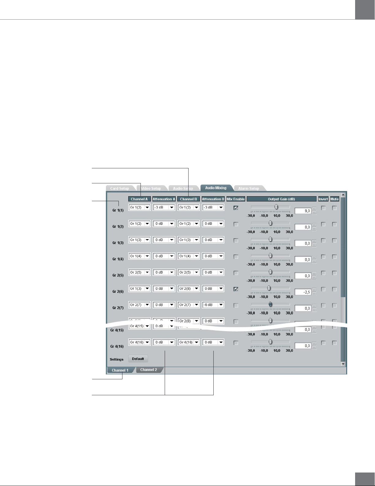
In the Audio Mixing window, users can map any of the audio channel
input to any audio channel output, mix pairs of channels and adjust audio
attenuation and gain, and invert and mute audio channels independently
for the video channel 1 and channel 2.
Output Audio Channel
Settings applied to
video channel 1
Attenuation is only available
when mixing 2 channels
The FRS-1002 card supports 16 audio channels in 4 groups. In the Audio
Mixing Window, the audio channels are identified by group «Gr1, Gr2,
Gr3, Gr4», and by channels «(1), (2), (3), (4), (5), (6),» etc. As an example,
Gr3(18) represents the audio channel input 18, in the third audio group.
23
Page 24
FRS-1002-MD / FRS-1002-MD-LG-PA
Has no effect on channels
that are not mixed
Guide to installation and operation
Channel A, Channel B
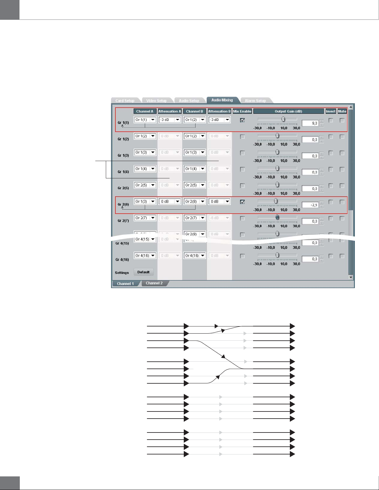
Channel A represents a single audio channel. It can be mapped to any
other channel output as is, or be mixed with another audio channel.
Channel B represents the audio channel that is mixed to the first audio
channel before being mapped to an output channel.
As an example, consider the following settings:
Gr1(1)
Gr1(2)
Gr1(3)
Gr1(4)
Gr2(4)
Gr2(6)
Gr2(7)
Gr2(8)
Gr3(9)
Gr3(10)
Gr3(11)
Gr3(12)
Gr4(13)
Gr4(14)
Gr4(15)
Gr4(16)
channel 1
channel 2
channel 3
channel 4
channel 5
channel 6
channel 7
channel 8
channel 9
channel 10
channel 11
channel 12
channel 13
channel 14
channel 15
channel 16
The above settings would have the following results:
Input Output
Audio Group 1
Audio Group 2
Audio Group 3
Audio Group 4
Channel A
Channel B
Channel A
No output
Channel B
Audio Group 1
Audio Group 2
Audio Group 3
Audio Group 4
channel 1 Gr1(1) + Gr1(2)
channel 2
channel 3
channel 4
channel 5
channel 6
channel 7
channel 8
channel 9
channel 10
channel 11
channel 12
channel 13
channel 14
channel 15
channel 16
Gr1(2)
Gr1(3)
Gr1(4)
Gr2(5)
Gr1(3) + Gr2(8)
Gr2(7)
Gr2(8)
Gr3(9)
Gr3(10)
Gr3(11)
Gr3(12)
Gr4(13)
Gr4(14)
Gr4(15)
Gr4(16)
24
Page 25

Guide to installation and operation
FRS-1002-MD / FRS-1002-MD-LG-PA
Attenuation A, Attenuation B
Audio attenuation can be set for mixed channels only, and will have no
effect on a single channel that is not paired with another. Attenuation can
be set to:
• 0 dB
• -3 dB
• -6 dB
Mix Enable
The Mix Enable check box must be checked in order for two audio
channels to be mixed.
Output Gain
The audio Output Gain can be adjusted from -30 dB to 30 dB in 0.5 dB
increments on single audio channels and on mixed audio channels.
Invert
You can perform phase inversion on single audio channels and on mixed
audio channels, by checking the Invert check box.
Mute
You can mute single audio channels and mixed audio channels, by
checking the Mute check box.
25
Page 26
FRS-1002-MD / FRS-1002-MD-LG-PA
The Alarm Setup Window
Alarms reported to Dashboard
Alarms reported to card’s LED
Card status (DS1)
Input 1(DS2)
Input 2 (DS3)
Not used (DS4)
Not used (DS5)
Card Reference (DS6)
FRS-1002-MD
Guide to installation and operation
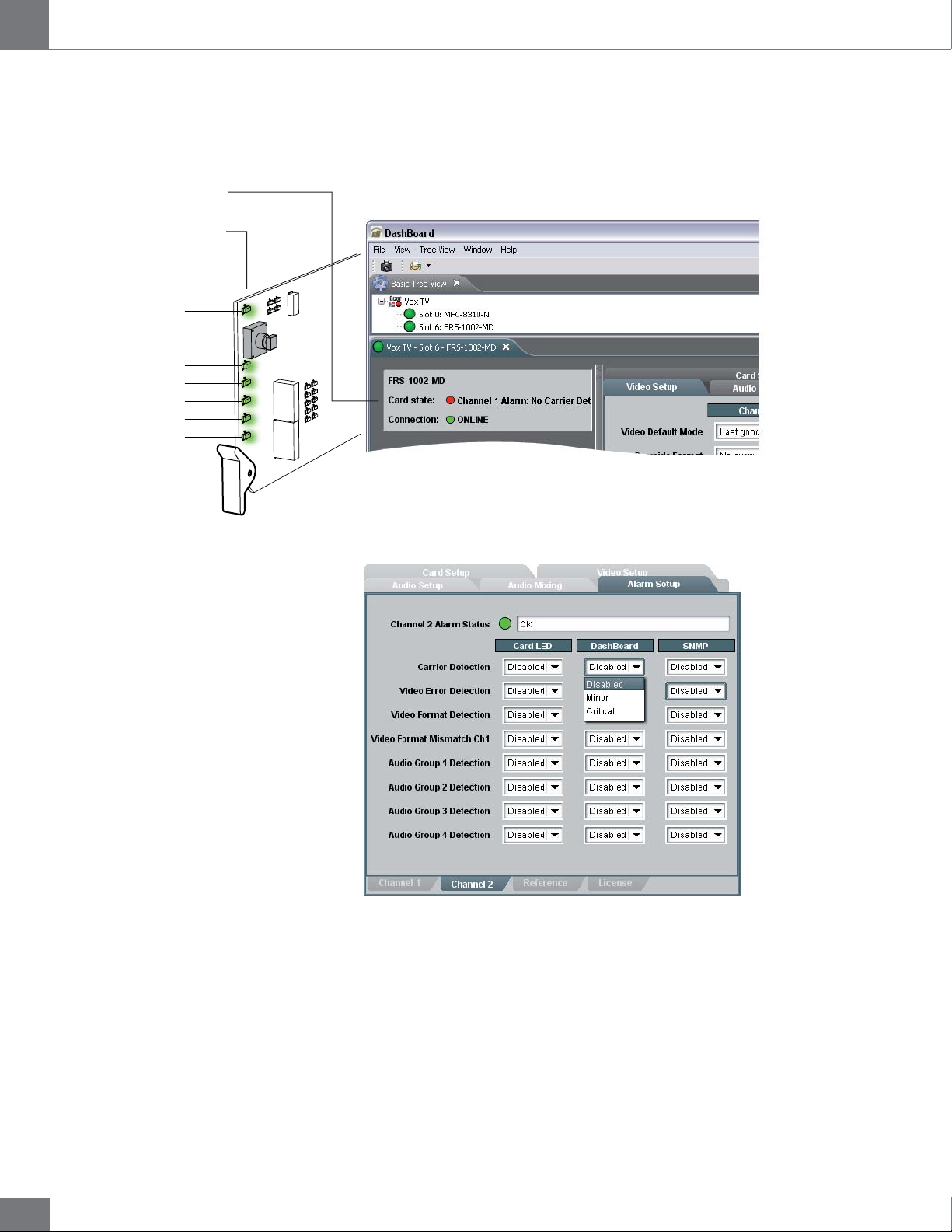
Problems detected by the FRS-1002 card are transmitted as alarms
to the card’s LED, to the Dashboard interface, and to the optional SNMP
monitoring. The problems detected can be reported to the user as minor
alarms or critical alarms.
The Alarm Setup window allows the user to set the alarm level at which
many types of errors will be reported to the LEDs or to Dashboard,
independently for channel 1 and 2, for the reference signal and for the
license key detection. The alarm signals can also be disabled.
Minor: When the alarm level for a specific type or error is set to minor,
the card’s LED will report the problem with a yellow light and Dashboard
with a yellow circle next to an error message describing the problem.
26
Critical: When the alarm level for a specific type or error is set to critical,
the card’s LED will report the problem with a red light and Dashboard with
a red circle next to an error message describing the problem.
Carrier and video detection errors on input 1 are always reported as
critical and cannot be set otherwise.
The Alarm Setup settings are automatically saved to memory and are
recalled after a power-up.
Page 27
Guide to installation and operation
How to Repurpose your Algogear Card
FRS-1002-MD / FRS-1002-MD-LG-PA
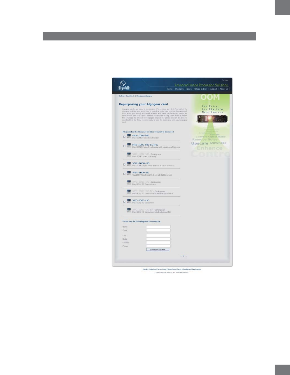
Algogear cards are easy to reconfigure. First, visit our website in the
support section, at: http://www.algolith.com/support/downloads/
repurpose-algogear
You will find a list of the Algogear products available for you.
Select the Algogear solution you would like to download onto your existing
Algogear card. Next enter your name and email address and press the
Download Solution button. An email will be sent to you with a link to
retrieve the download file for your new Algogear application.
Save the file on the PC which you will use to run Dashboard and access
the Algogear card you want to repurpose. You are now ready to load the
application onto your Algogear card.
27
Page 28
FRS-1002-MD / FRS-1002-MD-LG-PA
Load the new product onto your card
Guide to installation and operation
The instructions below will help you quickly and easily repurpose your
Algogear card with a new Algogear application. Please take the time to
read through the steps before beginning the process so that you have all
the necessary information on hand before you begin.
Repurposing an Algogear card can only be done through the 1.
Dashboard software application (to download Dashboard visit
http://www.algolith.com/support/downloads/index.html).
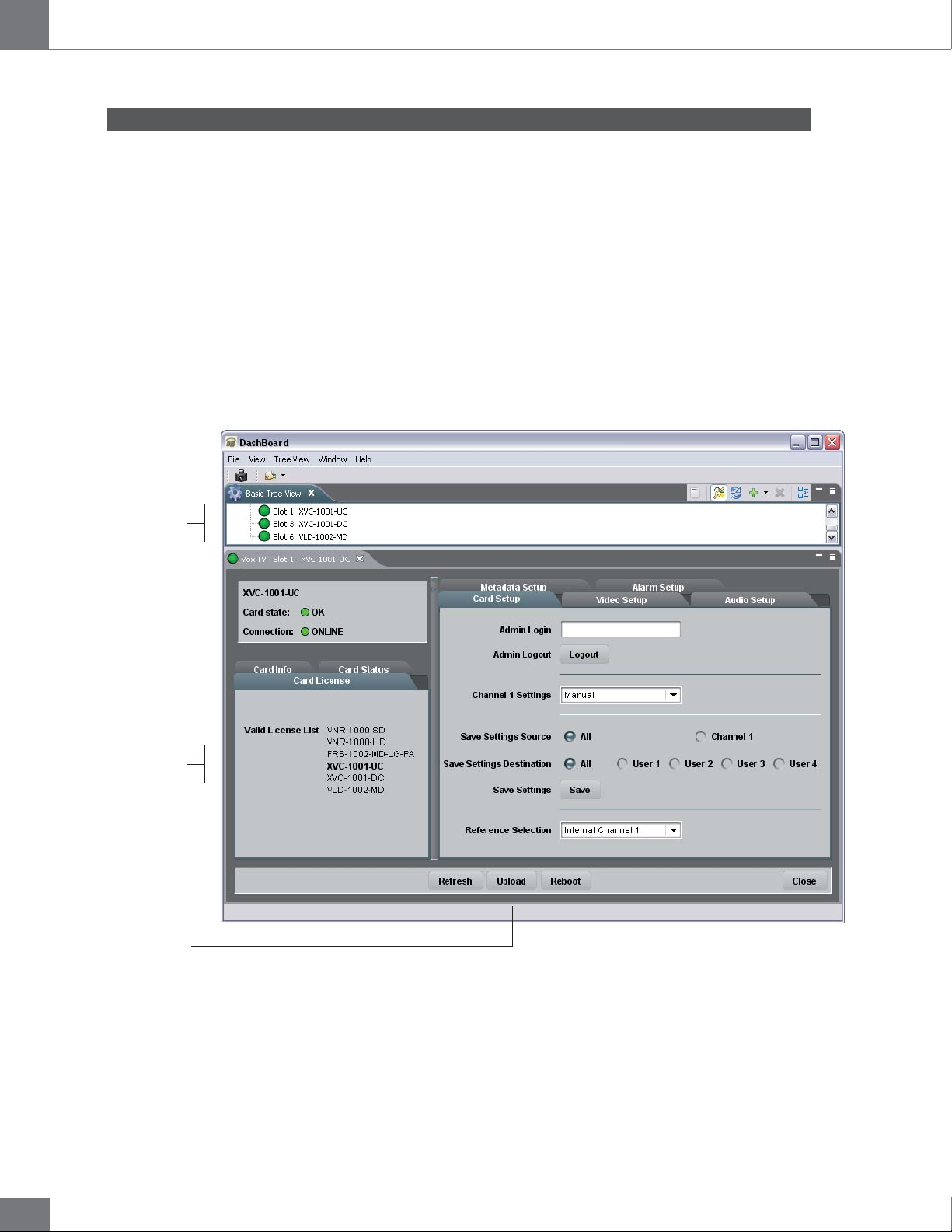
In order to repurpose your Algogear card, you will need to
be able to access it in Dashboard.
Before you repurpose your Algogear card with a new applica-2.
tion, view the application licenses that are authorized to run on
your Algogear card by selecting the Card License info tab in
Dashboard.
Select the card you
want to repurpose
The selected card can
be repurposed to any
of the Algogear products
listed in the Card
License tab
Click on the Upload button
to select the .BIN file you
have downloaded from
Algolith’s website
NOTE: If you cannot find the license for the application you want to
program the card with, or you cannot find the Card License info tab,
STOP IMMEDIATELY and call Algolith customer support at:
1.877.ALGOLITH ext 3509.
28
Now that you have validated the license, you are ready to repurpose 3.
your Algogear card with the .BIN file you have downloaded.
Page 29
Guide to installation and operation
FRS-1002-MD / FRS-1002-MD-LG-PA
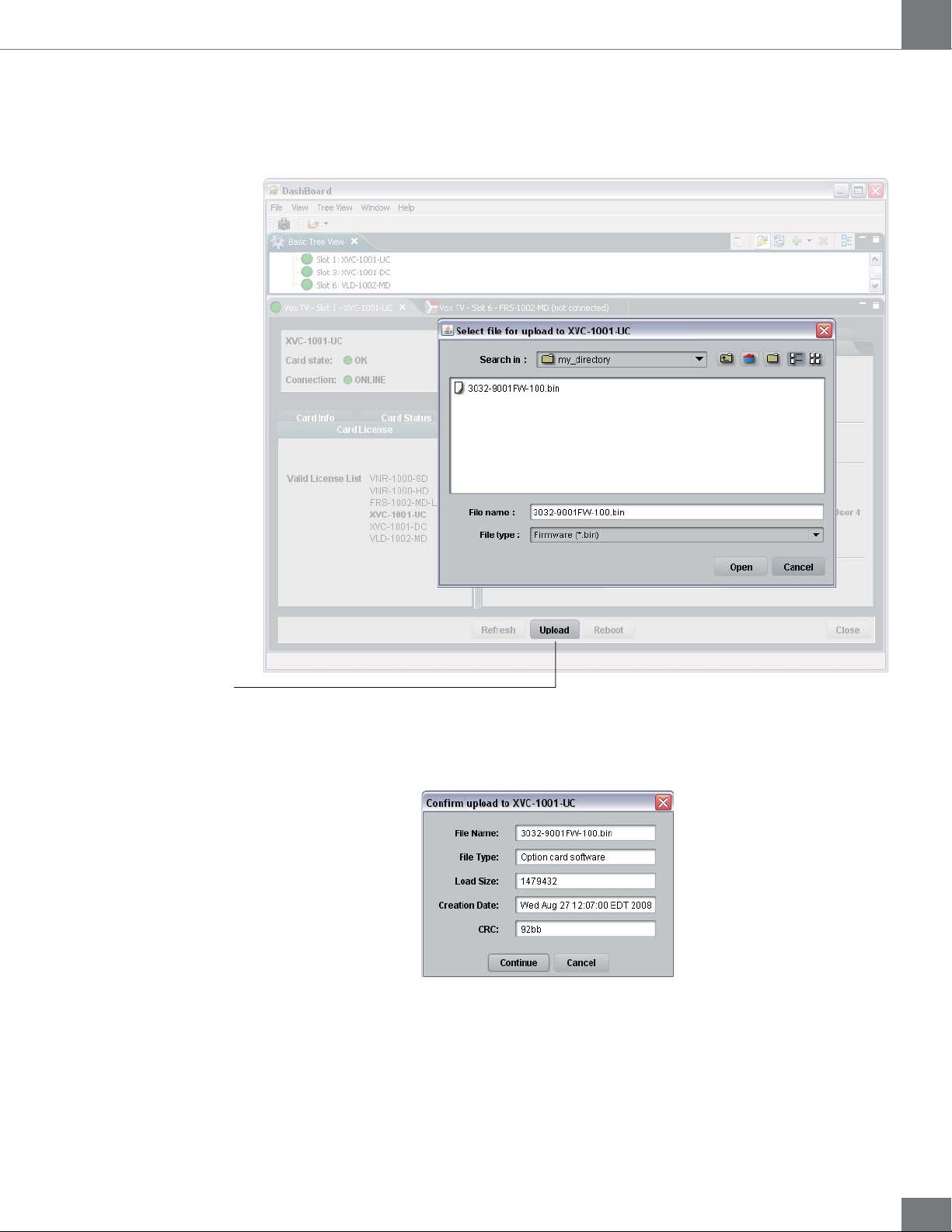
Next you will need to upload the downloaded file onto the 4.
Algogear card. Click on the Upload button to select the .BIN file
in the directory in which it is stored, and click the Open button.
Click Upload to get to
the .BIN file
You will get a confirmation dialog box that displays the selected
upload file name, type, size, and the file creation date. Click on
Continue to start the uploading process (an Uploading Progress
dialog box opens).
NOTE: Pressing the Cancel button while uploading will leave the card in
an invalid state. Do not click Cancel unless the uploading progress has
stopped completely for 60 seconds or more. The uploading process can
take a few minutes.
29
Page 30
FRS-1002-MD / FRS-1002-MD-LG-PA
Card is in the process of
being repurposed
Guide to installation and operation
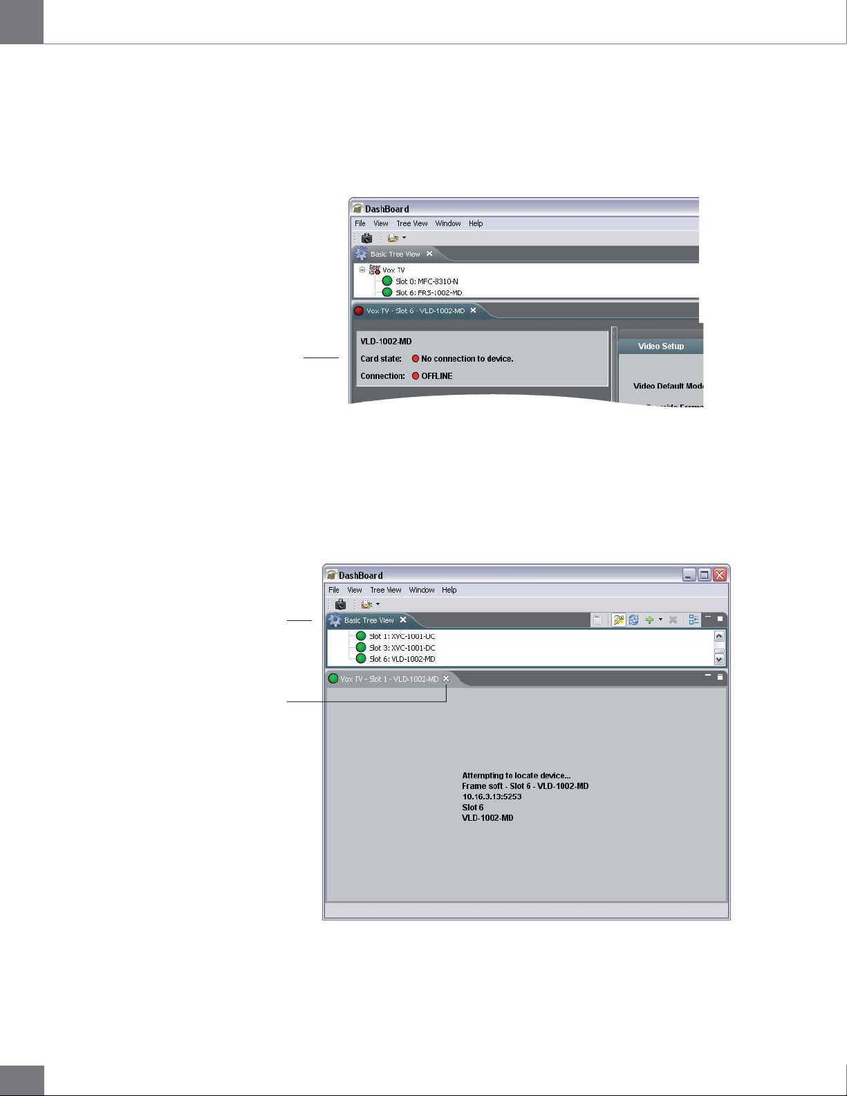
Be patient! The upgrade process can take a few minutes. While the 5.
files are being decompressed, the Dashboard user interface displays an «Upgrade in Progress» message. After decompression,
the files are installed and Dashboard loses connection with the card.
An error message is then displayed. See graphic below.
This step is normal in the upgrade process and must not be
interrupted.
Basic Tree View
Close the device window
displaying the Algogear card
that is no longer valid
When the repurposing process is completed, Dashboard can no lon-6.
ger locate the functions of the initial card and the menu disapears.
You will need to close the current device view in Dashboard as it is
no longer valid and re-open the device from the Basic Tree View.
30
Page 31

Guide to installation and operation
FRS-1002-MD / FRS-1002-MD-LG-PA
Once the card has rebooted, you should see the name of 7.
the new Algogear product you have installed on the dot
matrix display located on the board.
XVC1001U
Dot matrix display
ALGOGEAR
NOTE: If you don’t see the product name, but instead the following
message: “LICENSE?”, an error has occurred with the license file
and you should contact Algolith customer support immediately for
assistance at 1.877.ALGOLITH ext 3509.
Many stickers and labels were provided with your original purcha-8.
se, in order for you to be able to identify your card and the rear
module BNCs correctly in the event that you repurposed your
card. Select the appropriate labels and install them as follows:
XVC-1001-UC
XVC-1001-UC
XVC-1001-DC
XVC-1001-UC
XVC-1001-UC
XVC-1001-DC
XVC-1001-UC
XVC-1001-UC
VLD-1002-MD
VNR-1000-SD
XVC-1001-UC
VLD-1002-MD
VNR-1000-SD
XVC-1001-UC
VLD-1002-MD
FRS-1002-MD
XVC-1001-UC
XVC-1001-UC
FRS-1002-MD
XVC-1001-UC
XVC-1001-UC
XVC1001U
VLD-1002-MD
ALGOGEAR
Labels of all Algogear products
provided with your original purchase
Replace ID label on card Replace rear module label on frame
4
3
XVC-1001-UC
XVC-1001-UC
XVC-1001-UC
XVC-1001-UC
34
XVC-1001-UC
VNR-1000-SD
XVC-1001-UC
INPUT 1
FILL 1
SAFE 1
XVC-1001-UC
1B
1A
1C
31
Page 32

FRS-1002-MD / FRS-1002-MD-LG-PA
Guide to installation and operation
Congratulations, you have successfully repurposed your Algogear card.
To request new rear module labels and card labels, email your name,
shipping address, phone number and the Algogear applications you
require at [email protected].
32
Page 33

Guide to installation and operation
Specifi cations*
FRS-1002-MD / FRS-1002-MD-LG-PA
SD/HD SDI Video
Signal: SD (SMPTE 259M-C) (270 Mbps)
HD (SMPTE 292M) (1.485, 1.485/1001 Gbps)
Formats: SD 480i59.94, 576i50
HD 720p50, 720p59.94, 720p60, 1080i50, 1080i59.94, 1080i60
Format autodetected
Ancillary Data: Passthrough
Video Inputs
Connectors: Two (2) BNC
Return Loss: SD >21 dB up to 270 Mbps
HD >14 dB up to 1.5 Gbps
Impedance: 75 Ω unbalanced
Video Outputs
Connectors: Four (4) BNC
Return Loss: SD >17 dB up to 270 Mbps
HD >11 dB up to 1.5 Gbps
Jitter: SD < 0.2 UI
HD < 0.3 UI
Impedance: 75 Ω unbalanced
Reference
Connector: One (1) BNC, SMPTE 170
bi-level, tri-level
Control:
Inputs: One (1) RJ-45 on frame
Software: Dashboard
Emedded Audio: Automatic Detection
Power: 14 W
* Specifications are subject to change without notice.
33
Page 34

FRS-1002-MD / FRS-1002-MD-LG-PA
Limited Warranty
Limited Warranty Coverage
Algolith Inc. warrants that the equipment it manufactures shall be free
from defects in material and workmanship for a period of two (2) years
from the date of purchase. If equipment fails due to such defects, Algolith
Inc. will, at its option, repair or provide a replacement for the defective
part or product.
Equipment that fails after the warranty period, has been operated or
installed in a manner other than that specified by Algolith, or has been
subjected to abuse or modification, will be repaired for time and material
charges at the Buyer’s expense.
All out-of-warranty repairs are warranted for a period of ninety (90) days
from the date of shipment from the factory.
A purchase receipt or other proof of the original purchase date is required
for warranty service.
Algolith Inc. makes no other warranties, expressed or implied, of
merchantability, fitness for a particular purpose or otherwise. Algolith’s
liability for any cause, including breach of contract, breach of warranty,
or negligence, with respect to products sold by it, is limited to repair or
replacement by Algolith, at its sole discretion.
Contact us
In no event shall Algolith Inc. be liable for any incidental or consequential
damages, including loss of profits.
Algolith Inc.
400 Isabey
Montréal, Québec, Canada
H4T 1V3
t. 514.335.9867
t. 877.ALGOLITH
f. 514.333.9873
Via Internet
General Information: [email protected]
Visit us at:
www.algolith.com
34
Page 35

Guide to installation and operation
S-
02
/
/
S-1002-M-M-P-PAA
id
i
toto
i i
i
s
tatataon erat
io
n
FRS-1002-MD / FRS-1002-MD-LG-PA
-M
35
 Loading...