

Page 1

ALESIS M20
RS-422
Implementation
Second Revision
August 5, 1999
Page 2

INTRODUCTION
This document contains information outlining the implementation of the Sony 9-Pin
Protocol in the Alesis M20. This is not an official Sony 9-pin protocol document and
should not be viewed as such. It is for reference purposes only. To obtain official Sony 9pin protocol documents, contact Sony directly.
INTERFACE SYSTEM OVERVIEW
• Conforming to EIA RS-422A
• Four-wire communications channel is utilized
• Data is transmitted asynchronously, bit serial, word serial with data transmissions between
devices being digital
• Standard transmission rate on the interface bus is 38.4 kilobits per second (kb/s)
• The data utilized by the interface system shall be as follows:
1 START Bit + 8 DATA Bits + 1 PARITY Bit + 1 STOP Bit
START
BIT
D0
(LSB)
Odd Parity means that the sum of D0 + D1 + … + D7 + PARITY equals an odd number.
D1
D2 D3 D4 D5 D6
D7
(MSB)
PARITY
(ODD)
STOP
BIT
MARK
SPACE
Alesis M20 RS-422 Document ……………………………….........………………………………Page 2
Page 3
COMMAND BLOCK FORMAT
The definition of CONTROLLER and DEVICE throughout this document shall be as follows:
“CONTROLLER” refers to the unit which controls the VTR.
“DEVICE” refers to the unit (VTR) which is controlled.
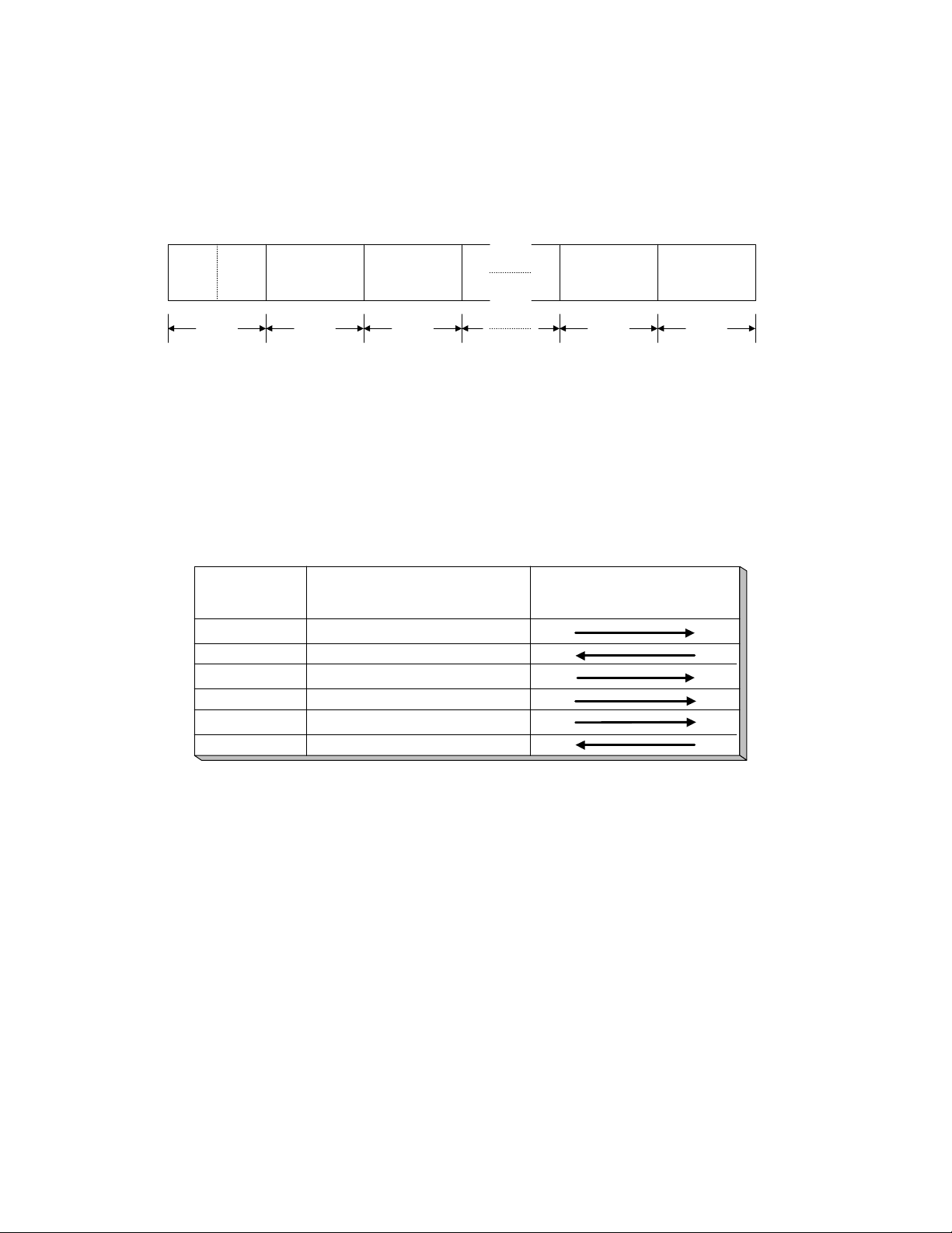
The communication between the CONTROLLER and DEVICE is composed of the following:
MSD LSD
Data
Cmd 1 Count Cmd 2 Data -1 Data-n Checksum
1 Byte 1 Byte 1 Byte 1 Byte 1 Byte
When the Data Count is zero, the Data is not transmitted. When it is not zero, the Data corresponding to the value is
inserted between Cmd 2 and Checksum.
Cmd 1
Cmd 1 classifies the COMMAND into main groups which indicate the Function and Direction of the data to
follow.
(n = max 15)
CMD 1
0
1
System Control Return
2
4
Preset & Select Control
6
7
Data Count
Data Count indicates the number of data bytes added following Cmd 2. It ranges from 0 to F.
Cmd 2
Cmd 2 is the designated COMMAND sent to the DEVICE or returned from the DEVICE.
Data
The number of data bytes and the content is defined by the specific Cmd 2.
FUNCTION
CONTROLLER DEVICE
System Control
Transport Control
Sense Request
Sense Return
DIRECTION
Checksum
The Checksum is the sum of all bytes in the message, from Cmd 1/Data Count to the last byte before the
Checksum. The Checksum is used to verify data accuracy and reject communication sequences that contain bit
errors.
Alesis M20 RS-422 Document ……………………………….........………………………………Page 3
Page 4

CONNECTOR PIN ASSIGNMENT
The interface connector is a 9-pin D-subminiature female connector. The pin assignment for the
CONTROLLER and DEVICE is as shown in the following table:
PIN CONTROLLER DEVICE
1 Ground Ground
2 Receive A Transmit A
3 Transmit B Receive B
4 Transmit Common Receive Common
5 Spare Spare
6 Receive Common Transmit Common
7 Receive B Transmit B
8 Transmit A Receive A
9 Ground Ground
COMMUNICATION PROTOCOL
All communication between CONTROLLER and DEVICE are under the direct supervision of the
CONTROLLER.
The CONTROLLER shall not transmit additional Command Blocks to the DEVICE prior to receiving an
appropriate response to the previous Command Block.
The CONTROLLER shall not interrupt transmission of a byte in a Command Block for more than 10
milliseconds. A DEVICE detecting the interruption of a byte in a Command Block that exceeds 10 ms
shall execute a Time-Out error sequence. A DEVICE shall void the receiving Command Block and
transmit a NAK (Time-Out).
The DEVICE, following the receipt of a Command Block from the CONTROLLER shall transmit a
response within 9 milliseconds.
The DEVICE, upon detection of an error, shall immediately transmit a NAK to the CONTROLLER, with
the appropriate error code. The CONTROLLER, upon receipt of the NAK, shall immediately stop
transmission of the Command Block
The M20 is a DEVICE (i.e. it only responds to and does not generate Sony 9-Pin commands). In general,
the M20 responds to commands in the following manner:
1) Recognized/supported command:
• Return an ACK as response to command not requiring data.
• Return appropriate data requested.
2) Checksum mis-match:
• Return a NAK (with data=checksum error) and take no action.
3) Unrecognized/unsupported command:
• Return a NAK (with data=undefined error) and take no action.
4) Number of data bytes is less than expected (e.g. Data byte count < # of bytes needed)
• Return a NAK (with data=undefined error) and take no action.
5) If more than 10 milliseconds lapses between bytes in a command block:
• Return a NAK (with data=timeout error) and take no action.
Alesis M20 RS-422 Document ……………………………….........………………………………Page 4
Page 5

COMMAND/RESPONSE CHART
The marks shown in the tables mean the following:
“O”
“*” indicates that the appropriate status bits are set, but the M20 does nothing;
“X” indicates that this command is not supported; returns a NAK Undefined (11.12.01)
COMMAND M20 RESPONSE
00.0C Local Disable O
00.1D Local Enable O
00.11 Device Type Request O
01.80 Memory Area Number Preset X
00.81 Memory Area Number Sense X
04.82 Memory Area Length Preset X
00.83 Memory Area Length Sense X
01.84 Memory Area Select X
00.85 Memory Area Select Sense X
01.86 Mem Area Output Select X
00.87 Mem Area Output Select Sense X
indicates that response to this command is supported; returns appropriate response
returns an ACK (10.01)
20.00 Stop O
20.01 Play O
20.02 Record O
20.04 Standby Off O
20.05 Standby On O
20.0F Eject O
20.10 Fast Forward O
2X.11 Jog Fwd O
2X.12 Var Fwd O
2X.13 Shuttle Fwd O
20.20 Rewind O
2X.21 Jog Rev O
2X.22 Var Rev O
2X.23 Shuttle Rev O
Alesis M20 RS-422 Document ……………………………….........………………………………Page 5
Page 6

COMMAND M20 RESPONSE
20.30 Preroll O
24.31 Cue With Data O
2X.37 Chase O
21.38 Prog Speed + O
21.39 Prog Speed - O
20.40 Preview O
20.41 Review O
20.42 Auto Edit O
20.54 Anti-Clog Timer Disable O
20.55 Anti-Clog Timer Enable O
20.60 Full EE Off O
20.61 Full EE On O
20.63 Select EE On O
20.64 Edit Off O
20.65 Edit On O
20.6A Freeze Off *
20.6B Freeze On *
20.80 Memory Stop X
20.81 Memory Play X
20.82 Memory Write Start X
20.93 Memory Read Fwd X
22.A3 Memory Red Rev X
26.B1 Memory Rd-Pointer Preset X
44.00 Timer-1 Preset X
44.04 TimeCode Gen Preset O
44.05 TimeCode Gen UBit Preset O
40.08 Timer-1 Reset O
40.10 In Entry O
40.11 Out Entry O
40.12 A In Entry O
40.13 A Out Entry O
44.14 In Data Preset O
44.15 Out Data Preset O
Alesis M20 RS-422 Document ……………………………….........………………………………Page 6
Page 7

COMMAND M20 RESPONSE
40.16 A In Entry Preset O
40.17 A Out Entry Preset O
40.18 In Shift + O
40.19 In Shift - O
40.1A Out +Shift O
40.1B Out -Shift O
40.1C A In +Shift O
40.1D A In -Shift O
40.1E A Out +Shift O
40.1F A Out -Shift O
40.20 In Flag Reset O
40.21 Out Flag Reset O
40.22 A In Flag Reset O
40.23 A Out Flag Reset O
40.24 In Recall O
40.25 Out Recall O
40.26 A In Recall O
40.27 A Out Recall O
40.2D Lost Lock Reset *
4x.30 Edit Preset O
44.31 Preroll Duration Preset O
41.32 Tape/Auto Select X
41.33 Servo Reference Select X
4x.34 Head Select X
41.35 Color Frame Select X
41.36 Timer Mode Select O
41.37 Input Check X
44.3C Postroll Duration Preset O
40.40 Auto Mode Off O
40.41 Auto Mode On O
40.42 Spot Erase Off X
40.43 Spot Erase On X
40.48 Video Reference Disable Off X
40.49 Video Reference Disable On X
42.50 DA Input Select X
42.51 DA Sys Emph Select X
41.58 DA Sys Fs Select X
45.78 Chase Offset O
Alesis M20 RS-422 Document ……………………………….........………………………………Page 7
Page 8

COMMAND M20 RESPONSE
4X.A0 Audio Input Level X
4X.A1 Audio Output Level X
61.0A TC Gen Data Sense O
61.0C Current Time Sense O
60.10 In Data Sense O
60.11 Out Data Sense O
60.12 A In Data Sense O
60.13 A Out Data Sense O
61.20 Status Sense O
62.23 Signal Cont Data Sense X
61.2A HM Data Sense X
61.30 Edit Preset Sense O
60.31 Preroll Duration Sense O
60.33 Servo Reference Select Sense X
60.36 Timer Mode Sense O
60.3C Postroll Duration Sense O
60.50 DA Input Sense X
60.51 DA Sys Emph Sense X
60.52 DA Input Emph Sense X
60.53 DA PB Emph Sense X
60.58 DA Sys Fs Sense O
61.78 Chase Offset Sense O
Alesis M20 RS-422 Document ……………………………….........………………………………Page 8
Page 9

M20 COMMAND RESPONSE DETAIL
M20 Responses
10.01 ACK
- Sent in response to receiving a valid command that does not require data.
12.11 Device Type Return
- Sent as response to Device Type Request command.
- The M20 responds as a Sony BVW-75: 2x 25
where x is TC frame rate: 0=29.97 or 30, 1=25, 2=24
11.12 NAK
- Sent when detecting communication errors or as response to receiving an
undefined command.
- Data Format:
BIT7 BIT6 BIT5 BIT4 BIT3 BIT2 BIT1 BIT0
TIME OUT
FRAMING
ERROR
OVERRUN
ERROR
PARITY
ERROR
CHECKSUM
ERROR
UNDEFINED
COMMAND
SYSTEM CONTROL
00.0C Local Disable
Action: Put M20 into Remote Only Mode (ONLINE CTRL: Remote)
00.1D Local Enable
Action: Put M20 into Local/Remote Mode (ONLINE CTRL: Local/Rem)
00.11 Device Type Request
Action: None
Response: Device Type = 12.11 Data = 2x yy
x is the TC frame rate: 0=30 frm, 1=25 frm, 2=24 frm
yy is the device id: 25h = BVW-75
Alesis M20 RS-422 Document ……………………………….........………………………………Page 9
Page 10

When both DATA-1 (N) and DATA-2 (N’) are given,
TRANSPORT CONTROL
• Chase mode is automatically cancelled by all "2x" commands, except 2x.37, 20.60,
20.61, 20.63, 20.64, and 20.65.
20.00 Stop
Action: Stop the tape
20.01 Play
Action: Play the tape
20.02 Record
Action: Record (Punch-In Only) from any state. Any other transport
command, except Eject and Standby Off, will cause a record exit.
20.03 Standby Off
Action: If already in standby, then unthread the tape (stop in mode1)
If not in standby, then do nothing (just send ACK)
20.04 Standby On
Action: Pause the tape (stop in mode2)
Standby = Stopped with the tape threaded.
20.0F Eject
Action: Eject the tape.
If recording, do nothing (just send NAK data=undefined)
20.10 Fast Forward
Action: Forward the tape
2X.11 Jog Forward
2X.12 Var Forward
2X.13 Shuttle Forward
Data: DATA-1 = N = Coarse speed variable (required)
DATA-2 = N’ = Fine speed variable (optional)
Action: Estimate speed closest to M20 capabilities.
20.20 Rewind
Action: Rewind the tape (threaded or unthreaded)
2X.21 Jog Rewind
2X.22 Var Rewind
2X.23 Shuttle Rewind
Data: DATA-1 = N = Coarse speed variable (required)
DATA-2 = N’ = Fine speed variable (optional)
Action: Estimate speed closest to M20 capabilities.
When only DATA-1 (N) is given,
Tape Speed = 10
Tape Speed = 10
((N/32)-2)
10
Alesis M20 RS-422 Document ……………………………….........………………………………Page 10
)
((N/32)-2)
((N/32)-2)
+ (N’/256)(10
(N-(1/32)-2)
-
Page 11

20.30 Preroll
Action: Set the Preroll bit (Status4, bit0) and locate to the PunchIn Point -
Preroll time.
24.31 Cue Up With Data
Data: DATA-1=Frame,
DATA-2=Seconds,
DATA-3=Minutes,
DATA-4=Hours
• All data bytes are in BCD format (ms nibble=tens; ls nibble=ones)
Action: Set the CueUp bit (Status4,bit0) and locate to specified time. Once the
locate has completed, set the CueUpComplete bit (Status2,bit0)
2X.37 Chase
Data: DATA-1: Synchronization method
00= Lock to reference when Chase Lock has been completed (Once)
01= Always continue the Chase operation (Cont)
Action: Synchronize to external timecode, using the Sync Offset
21.38 Program Speed Play+
Data: DATA-1 = 8-bit Speed Value that ranges from 0 to 60 (0..3CH)
Deviation(% )= 0.1 x Speed Value
Action: Positive Pitch change
21.39 Program Speed Play-
Data: DATA-1 = 8-bit Speed Value that ranges from 0 to 60 (0..3CH)
Deviation(% )= -0.1 x Speed Value
Action: Negative Pitch change
Alesis M20 RS-422 Document ……………………………….........………………………………Page 11
Page 12

20.40 Preview
Action:
Locate to PunchIn-Preroll time and enter record. At PunchIn point, crossfade (at In
Point crossfade time preset) with input data. At PunchOut point, crossfade (at Out
Point crossfade time preset) with tape playback data. If not chasing, the tape will
stop when it reaches the PunchOut+Postroll time. If chasing, the tape will continue
to follow the incoming timecode. For the M20, this means the following:
1) Enable Preroll, Postroll, Rehearse and AutoRecord.
2) Locate to the AutoPunchInPoint - Preroll time
3) Initiate a record which puts the M20 into auto record rehearse mode
(which will crossfade in and out at PunchIn and PunchOut points)
4) Restore original Preroll, Postroll, AutoPlay, and AutoReturn status at the
PunchOut+Postroll time.
20.41 Review
Action:
Locate to PunchIn-Preroll time and enter play. If not chasing, the tape will stop
when it reaches the PunchOut+Postroll time. If chasing, the tape will continue to
follow the incoming timecode. For the M20, this means the following:
1) Enable Preroll and Postroll.
2) Locate to the AutoPunchInPoint - Preroll time
3) Initiate a play
4) Restore original Preroll, Postroll, AutoPlay, and AutoReturn status at the
PunchOut+Postroll time.
20.42 Auto Edit
Action:
Locate to PunchIn-Preroll time and enter play. At PunchIn point, crossfade (at In
Point crossfade time preset) with input data and enter EDIT REC mode. At
PunchOut point, crossfade (at Out Point crossfade time preset) with tape playback
data cancel EDIT REC mode and enter REPRO playback. If not chasing, the tape
will stop when it reaches the PunchOut +Postroll time. If chasing, the tape will
continue to follow the incoming timecode. For the M20, this means the following:
1) Enable Auto Record
2) Locate to PunchIn - Preroll time
3) Initiate a record, which plays the tape until PunchIn point is reached, at
which time it will punch-in, punch-out at PunchOut point.
4) Restore original Preroll, Postroll, AutoPlay, and AutoReturn status at
PunchOut+Postroll time. (If chasing, Auto Record will be disabled at the
PunchOut point)
20.54 Anti-Clog Timer Disable
Action: Disable the anti-clog timer, which is responsible for unthreading the tape
after the specified time without tape activity. When the timer is disabled,
the unthread timeout is infinite (no timeout). The previous timeout is still
retained so that enabling the timer will return to the previous timeout.
20.55 Anti-Clog Timer Enable
Action: Enable the anti-clog timer. Return the unthread timeout to the last non-
infinite value.
The unthread timeout value can be viewed and/or edited in the Utility pages.
(Currently, the user is not able to select the infinite setting from the front panel)
Alesis M20 RS-422 Document ……………………………….........………………………………Page 12
Page 13

20.60 Full EE Off
20.61 Full EE On
Action: Clears/sets all channels to EE (input) mode. (Disables/enables All Input)
20.62 Select EE On
Action: Sets each EDIT PRESET channel assigned by DATA-1 of EDIT
PRESET command to the EE mode (disable AutoInput)
20.63 Edit Off
Action: Cancels the EDIT REC mode as well as the SELECT EE mode (enable
AutoInput)
20.64 Edit On
Action: Enter EDIT REC PLAY mode (punch-in)
Alesis M20 RS-422 Document ……………………………….........………………………………Page 13
Page 14

PRESET/SELECT CONTROL
44.04 Time Code Generator Preset
Data: DATA-1 thru DATA-4 same format as in “44.00: Timer-1 Preset”
Action: Set (internal) timecode generator to the specified value
44.05 Time Code Generator User Bit Preset
Data: DATA-1=Binary Group 1&2; DATA-2=Binary Group 3&4;
DATA-3=Binary Group 5&6; DATA-4=Binary Group 7&8
• Data Format: ms nibble=Binary Grp N+1; ls nibble=Binary Grp N
Action: Set timecode generator user bits to the specified value
40.08 Timer-1 Reset
Action: Reset Timer-1 (ABS time) to zero (i.e. make current location the new
Relative Zero point)
40.10 In Entry
40.11 Out Entry
40.12 A In Entry
40.13 A Out Entry
Action: Transfer the timer or timecode data as In/Out Point data into the In/Out
Entry (Transfer timer or timecode data into the PunchIn/Out Point)
44.14 In Data Preset
44.15 Out Data Preset
44.16 A In Data Preset
44.17 A Out Data Preset
Data: DATA-1 thru DATA-4 same format as in “24.31: Cue Up With Data”
Action: Place specified data into In/Out Entry (set PunchIn/Out Point)
40.18 In Shift +
40.19 In Shift -
40.1C A In Shift +
40.1D A In Shift -
Action: Add/subtract 1 frame of timer or timecode value stored in the In Entry
as the In Point (Add/Subtract 1 frame from the MarkIn Point)
40.1A Out Shift +
40.1B Out Shift -
40.1E A Out Shift +
40.1F A Out Shift -
Action: Add/subtract 1 frame of timer or timecode value stored in the Out
Entry as the Out Point (Add/Subtract 1 frame from the MarkOut Point)
40.20 In Flag Reset
40.21 Out Flag Reset
40.22 A In Flag Reset
40.23 A Out Flag Reset
Action: Clear the IN flag (STATUS-3, Bit 0) or OUT flag (STATUS-3, Bit 1)
40.24 In Recall
40.25 Out Recall
40.26 A In Recall
40.27 A Out Recall
Action: Set the IN flag (STATUS-3, Bit 0) or OUT flag (STATUS-3, Bit 1)
Alesis M20 RS-422 Document ……………………………….........………………………………Page 14
Page 15

40.2D Lost Lock Reset
Action: Clear the LOST LOCK flag (STATUS-8, Bit 6)
4X.30 Edit Preset
Data: DATA-1 thru DATA-15
Action: If x=1, then DATA-1 enables/disables tracks 1, 2, TC
If x=2..F, then DATA-2 thru DATA-15=bitmap of cascaded units 1 thru 14
<data-1> = RS-422 Edit Preset data-1 format
Bit7 Bit6 Bit5 Bit4 Bit3 Bit2 Bit1 Bit0
TC Trk2 Trk1Assem VideoInsert
<data-2>...<data-15> = track bitmap of unit #1..unit #14
(0=track disabled, 1=track enabled)
Bit7 Bit6 Bit5 Bit4 Bit3 Bit2 Bit1 Bit0
Trk2 Trk1Trk3Trk4Trk5Trk6Trk7Trk8
44.31 Preroll Duration Preset
Data: DATA-1 thru DATA-4 same format as in “24.31: Cue Up With Data”
Action: Set Preroll Time (range 0 thru 25 secs)
41.36 Timer Mode Select
Data: DATA-1: 01=Timecode; 02=Timer-1 (ABS)
Action: Select timer system to be used as a basis for In Entry, Out Entry, In Preset,
Out Preset, Preroll and Cue Up With Data, etc.
44.3C Postroll Duration Preset
Data: DATA-1 thru DATA-4 same format as in “24.31: Cue Up With Data”
Action: Set Postroll Time
40.40 Auto Mode Off
40.41 Auto Mode On
Action: These commands are used for turning the AUTO mode of the DEVICE on/off.
44.78 Chase Offset Preset
Data: DATA-1=Frame,
DATA-2=Seconds,
DATA-3=Minutes,
DATA-4=Hours,
• All data bytes are in BCD format (ms nibble=tens; ls nibble=ones)
Action: Set Chase Offset
Alesis M20 RS-422 Document ……………………………….........………………………………Page 15
Page 16

SENSE REQUEST
61.0A TC Gen Data Sense
Data: DATA-1 = 01: Request for GEN TC
Response: 74.08: GEN TC DATA
- DATA-1 thru DATA-4 same format as in “24.31: Cue Up With Data”
Data: DATA-1 = 10: Request for GEN UB
Response: 74.09: GEN UB DATA
- DATA-1 thru DATA-4 same format as in “44.05: Time Code Generator
User Bit Preset”
Data: DATA-1 = 11: Request for GEN TC and GEN UB
Response: 78.08: GEN TC DATA
- DATA-1 thru DATA-4 same format as in “24.31: Cue Up With Data”
- DATA-5 thru DATA-8 same format as in “44.05: Time Code Generator
User Bit Preset”
61.0C Current Time Sense
Data: DATA-1 = 01: Request for LTC TIME
Response: 74.04: LTC TIME DATA
- DATA-1 thru DATA-4 same format as in “24.31: Cue Up With Data”
74.14: LTC INTERPOLATED TIME DATA
- DATA-1 thru DATA-4 same format as in “24.31: Cue Up With Data”
Data: DATA-1 = 04: Request for TIMER-1
Response: 74.00: TIMER-1 DATA
- DATA-1 thru DATA-4 same format as in “24.31: Cue Up With Data”
Data: DATA-1 = 10: Request for LTC USER BITS
Response: 74.05: LTC UB DATA
- DATA-1 thru DATA-4 same format as in “44.05: Time Code Generator
User Bit Preset”
Data: DATA-1 = 11: Request for LTC TIME & USER BIT DATA
Response: 78.04: LTC TIME & UB DATA
- DATA-1 thru DATA-4 same format as in “24.31: Cue Up With Data”
- DATA-5 thru DATA-8 same format as in “44.05: Time Code Generator
User Bit Preset”
78.14: LTC INTERPOLATED TIME & UB DATA
- DATA-1 thru DATA-4 same format as in “24.31: Cue Up With Data”
- DATA-5 thru DATA-8 same format as in “44.05: Time Code Generator
User Bit Preset”
Note: Respond with 70.0D: REQUEST TIME DATA MISSING if requested
data is other than Timer-1 or Timer-2 data, and when following conditions
exist:
• Immediately after power-on and until tape starts moving
• Cassette out
• During loading or unloading
Alesis M20 RS-422 Document ……………………………….........………………………………Page 16
Page 17

60.10 In Data Sense
60.11 Out Data Sense
Request In/Out Point data
Response: 75.10: IN DATA
- DATA-1 thru DATA-4 same format as in “24.31: Cue Up With Data”
75.11: OUT DATA
- DATA-1 thru DATA-4 same format as in “24.31: Cue Up With Data”
61.20 Status Sense
Request for status
Data: DATA-1 (MS nibble=initial status byte to be sent back)
(LS nibble=# of status bytes to be sent back)
Response: 7X.20: STATUS DATA
- DATA-1 thru DATA-x (Status Bytes) Reference Appendix A
61.30 Edit Preset Sense
Data: DATA-1 (MS nibble=initial status byte to be sent back)
(LS nibble=# of status bytes to be sent back)
Response: 7x.30: EDIT PRESET DATA
- DATA-1 thru DATA-x (Status Bytes)
60.31 Pre-roll Duration Sense
Request Pre-roll time data
Response: 74.31: PREROLL TIME DATA
- DATA-1 thru DATA-4 same format as in “24.31: Cue Up With Data”
60.36 Timer Mode Sense
Request for setting of the Timer Mode (Timer-1 or Timecode)
Response: 71.36: TIMER MODE STATUS
- DATA-1 = 00 for Timecode, =01 for Timer-1 (ABS)
60.58 DA Sys Fs Sense
Request digital audio channel sampling frequency
Response: 71.58: DA SAMPLING FREQ DATA
- DATA-1: 01=48KHz; 02=44.1KHz
61.78 Chase Offset Sense
Request Chase Offset value
Response: 76.78: CHASE OFFSET DATA
- DATA-1=00
- DATA-2=Frame, DATA-3=Seconds, DATA-4=Minutes
Notes
• In certain instances, the user may want to use ABS + SMPTE Offset instead of the TC
track timecode when controlling the M20 via RS-422. If the Chase Reference = Tape
TC, then the TC track timecode will be used and if the Chase Reference = ABS Time,
then the ABS + SMPTE Offset will be used. For example, when Chase Reference =
ABS Time, the M20 will respond to the timecode query with the ABS+SMPTE Offset
timecode. Also while Chase Reference = ABS Time, if the reference counter display is
in TapeTC mode, the ABS + SMPTE Offset timecode will be displayed instead of the
TC track timecode.
Alesis M20 RS-422 Document ……………………………….........………………………………Page 17
 Loading...