

Page 1

ALESIS
A6 Andromeda (A6)
Service Manual
P/N: 8-31-0089-C
ATTENTION!
THIS DOCUMENT CONTAINS SENSITIVE
PROPRIETARY INFORMATION. ALL
RECIPIENTS MUST HAVE A CURRENT NON-
DISCLOSURE AGREEMENT ON FILE WITH
ALESIS, LLC.
DO NOT DISTRIBUTE THIS DOCUMENT IN
ELECTRONIC FORM
The information in this document contains privileged and confidential information. It is intended
only for the use of those authorized by Alesis. If you are not the authorized, intended recipient,
you are hereby notified that any review, dissemination, distribution or duplication of this
document is strictly prohibited. If you are not authorized, please contact Alesis and destroy all
copies of this document. You may contact Alesis at support@Alesis.com.
Copyright © 2003 Alesis, LLC
Confidential Alesis Service Manual 8-31-0089-C
Page 2

Version History
Ver A: BRS: added new cover page, added Fatar key removal instructions.
Ver B: 6/13/02 BRS: added more debugging tips, added rev C main board.
Ver C: 10/30/03 ATM: Added additional warning information for Battery replacement (per UL)
Confidential Alesis Service Manual 8-31-0089-C
Page 3

Preface
This document is intended to assist the service technician in the operation, maintenance and
repair of the A6 Andromeda. Together with the A6 Reference Manual, this document provides a
complete description of the functionality and serviceability of the A6. Any comments or
suggestions you may have pertaining to the document are welcome and encouraged.
READ THIS!
In addition to any purchase price that Alesis may charge as consideration for Alesis
selling or otherwise transferring this service manual (“Manual”) to you, if you are not a
service and repair facility (“Service Center”) authorized by Alesis in writing to be an
authorized Service Center, Alesis sells or transfers the Manual to you on the following
terms and conditions:
Only Service Centers authorized by Alesis in writing are authorized to perform service
and repairs covered by an Alesis warranty (if any), and transfer of the Manual to you
does not
or if the Manual is used to perform, any service or repairs on any Alesis product or
part thereof, any and all warranties of Alesis as to that product and any service
contract with Alesis for that product shall be voided and shall no longer apply for
such product, even if your services or repairs were done in accordance with the
Manual.
authorize you to be an authorized Service Center. Therefore, if you perform,
All service or repairs done by you or with reference to the Manual shall be solely your
responsibility, and Alesis shall have no liability for any such repairs or service work.
All such service or repairs are performed at the sole risk of the person performing
the service or repairs. You agree that all such work will be performed in a competent,
professional and safe manner at all times and to indemnify and fully hold Alesis and its
successors and assigns harmless in the event of any failure to so perform.
Your purchase of the Manual shall be for your own ultimate use and shall not be for
purposes of resale or other transfer.
As the owner of the copyright to the Manual, Alesis does not give you the right to copy
the Manual, and you agree not to copy the Manual without the written authorization of
Alesis. Alesis has no obligation to provide to you any correction of, or supplement to,
the Manual, or any new or superseding version thereof.
Alesis shall have the right to refuse to sell or otherwise transfer repair parts or materials
to you in its sole discretion. You shall not use, sell or otherwise transfer spare or
replacement parts supplied by Alesis to you (i) to repair or be used in products
manufactured for or by third parties or (ii) to any third parties for any purpose.
You shall not make any warranties or guarantees with respect to the products of Alesis
or the use thereof on behalf of Alesis or in your own name.
The foregoing describes the entire understanding related to sale or transfer of the Manual
to you, and no other terms shall apply unless in a writing signed by an authorized
representative of Alesis.
All Trademarks are property of their respective companies.
Confidential Alesis Service Manual 8-31-0089-C
Page 4
Warnings
TO REDUCE THE RISK OF ELECTRIC SHOCK OR FIRE, DO NOT EXPOSE THIS
PRODUCT TO WATER OR MOISTURE.
The arrowhead symbol on a lightning flash inside a triangle is intended to alert the
user to the presence of un-insulated "dangerous voltage" within the enclosed
product which may be of sufficient magnitude to constitute a risk of electric shock
to persons.
The exclamation point inside a triangle is intended to alert the user to the presence
of important operating, maintenance and servicing instructions in the literature
which accompanies the product.
REPAIR BY ANY PERSON OR ENTITY OTHER THAN AN AUTHORIZED ALESIS
SERVICE CENTER WILL VOID THE ALESIS WARRANTY.
PROVISION OF THIS MANUAL DOES NOT AUTHORIZE THE RECIPIENT TO
COMPETE WITH ANY ALESIS DISTRIBUTOR OR AUTHORIZED REPAIR
SERVICE CENTER IN THE PROVISION OF REPAIR SERVICES OR TO BE OR
MAKE REPAIRS AS AN AUTHORIZED SERVICE CENTER.
ALL REPAIRS DONE BY ANY ENTITY OTHER THAN AN AUTHORIZED ALESIS
SERVICE CENTER SHALL BE SOLELY THE RESPONSIBILITY OF THAT ENTITY,
AND ALESIS SHALL HAVE NO LIABILITY TO THAT ENTITY OR TO ANY OTHER
PARTY FOR ANY REPAIRS BY THAT ENTITY.
Regarding the Power Supply Fuse
CAUTION: The product under service may employ the use of a
replaceable fuse. Danger of fire or electrocution if fuse is incorrectly
replaced. Replace with only the same type or equivalent type
recommended by the equipment manufacturer.
Regarding the Internal Battery
CAUTION: The product under service may employ the use of a internal
battery. Danger of explosion if battery is incorrectly replaced. Replace
only with the same or equivalent type recommended by the manufacturer.
Dispose of used batteries according to the manufacturer's instruction.
Confidential Alesis Service Manual 8-31-0089-C
Page 5

Safety Instructions
Carefully read the applicable items of the operating instructions and these safety suggestions
before using this product. Use extra care to follow the warnings written on the product itself and
in the operating instructions. Keep the operating instructions and safety suggestions for reference
in the future.
1. Power Source. The product should only be connected to a power supply which is described either in the
operating instructions or in markings on the product.
2. Power Cord Protection
and such that nothing will be placed on or against them.
3. Periods of Non-use
cord should be unplugged from the AC outlet.
4. Foreign Objects and Liquids
product.
5. Water or Moisture
6. Heat
7. Ventilation
8. Mounting
9. Cleaning
10. Service
. Do not place the product near heat sources such as stoves, heat registers, radiators or other heat producing
equipment.
. When installing the product, make sure that the product has adequate ventilation. Improperly
ventilating the product may cause overheating, which may damage the product.
. The product should only be used with a rack which the manufacturer recommends. The
combination of the product and rack should be moved carefully. Quick movements, excessive force or uneven
surfaces may overturn the combination which may damage the product and rack combination.
. The product should only be cleaned as the manufacturer recommends.
. The user should only attempt the limited service or upkeep specifically described in the operating
instructions for the user. For any other service required, the product should be taken to an authorized service
center as described in the operating instructions.
. AC power supply cords should be placed such that no one is likely to step on the cords
. If the product is not used for any significant period of time, the product's AC power supply
. Take care not to allow liquids to spill or objects to fall into any openings of the
. The product should not be used near any water or in moisture.
11. Damage to the Product
without limitation when:
a. Liquid has spilled or objects have fallen into the product,
b. The product is exposed to water or excessive moisture,
c. The AC power supply plug or cord is damaged,
d. The product shows an inappropriate change in performance or does not operate normally, or
e. The enclosure of the product has been damaged.
. Qualified service personnel should service the unit in certain situations including
Confidential Alesis Service Manual 8-31-0089-C
Page 6
1.0 Theory of Operation
d
p
The A6 is a 16-voice digitally-controlled real analog synthesizer.
The heart of the system is a Motorola Coldfire processor on the Main board. The code for the
Coldfire is in flash memory, and is upgradeable through MIDI. There is also a battery-backed
SRAM for holding user data.
There is a secondary processor on the Front Panel Left, an 87C52 running code from an
EPROM. This processor controls the LCD and does the LED muxing. It does not, however,
read the pot values. This is done by the Coldfire.
The analog sounds are generated from 8 Oscillator ASICs that feed 8 Filter ASICs. Each ASIC
contains two voices.
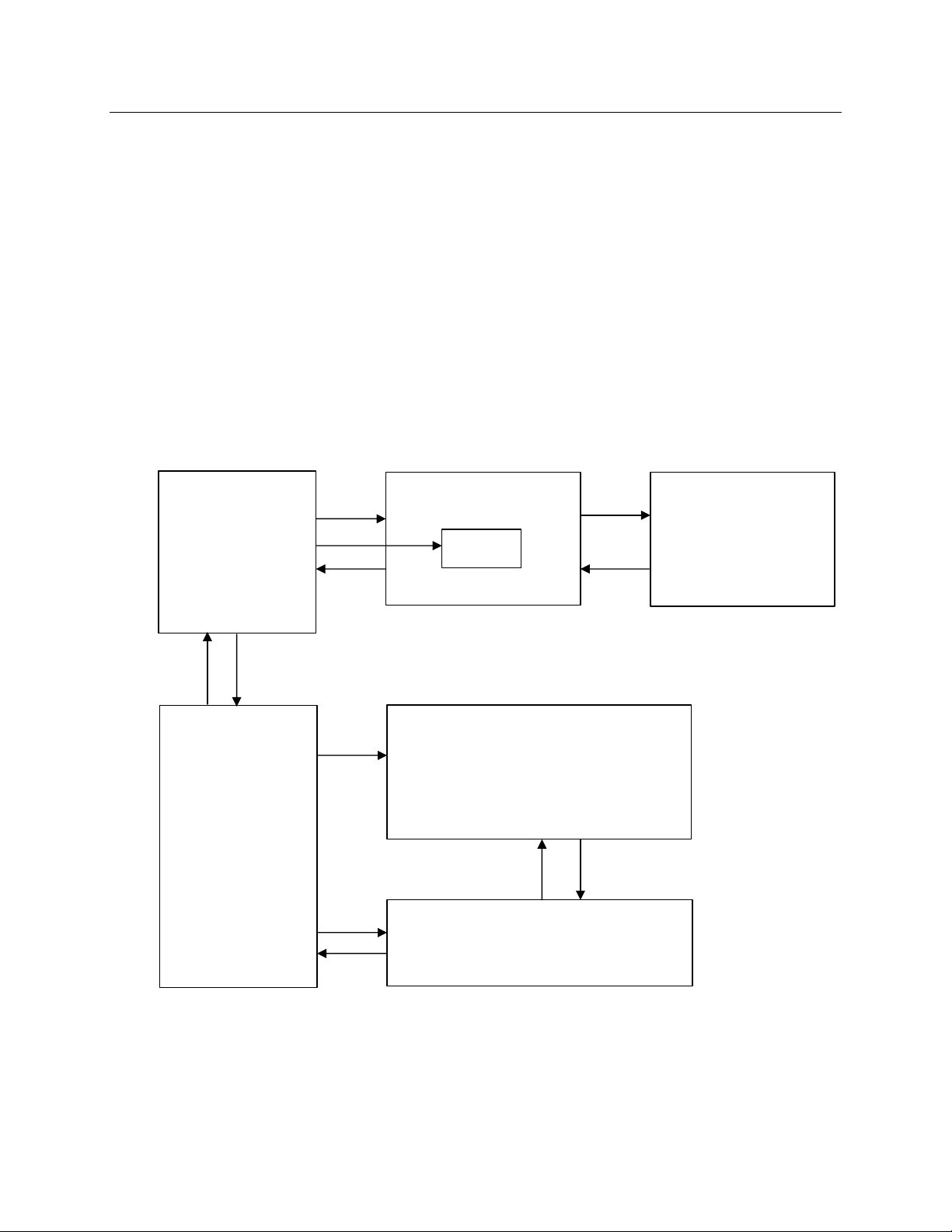
The diagram below shows the majorA6 PCBs and their functions:
Front Panel Left
Micro, EPROM,
LED muxing
pot muxing
switch matrix
LEDs
switches
pots
Analog pot
Control
voltages,
switch data
Main
Coldfire micro
address decoding
flash memory
keyscan ASIC
digital FX
pot/tuning ADC
tuning comparator
ASIC control
MIDI
foot pedals
power regulators
Control
LCD control
Analog pot
voltages,
switch
matrix
Databus
Control,
FX return
Tuning
signal, FX
sen
Front Panel Center
LEDs, switches, pots
Control
LCD
Analog pot
voltages,
switch
matrix
Analog ASIC
4 DACs for analog ASIC control signals
8 Oscillator ASICs
8 Filter ASICs
analog power regulators
Noise,
external
uts
in
Voice busses,
tuning,
FX busses
Analog Master
analog output circuitry (op amps)
analog distortion
analog noise generator
Front Panel Right
LEDs, switches, pots
Confidential Alesis Service Manual 8-31-0089-C
Page 7

2.0 Test Procedures
This document assumes basic familiarity with the A6 and the A6 User Manual. Please read
Appendix C of the A6 Reference Manual and familiarize yourself with it. It contains useful
information for troubleshooting.
2.10 Power Up Modes
You will need to know the A6 power up modes, since these will be helpful in debugging many
problems. The following chart is taken from the A6 User Manual:
POWER UP
WHILE HOLDING
Soft Button 1 Forces A6 to load default Program and Mix. This is useful if the A6 has received
Soft Button 2 Enters front panel debug mode.
Soft Button 3 Initializes all user RAM. This is also known as a Hard Reset. Warning, this will
FUNCTION
corrupted data, causing it to hang.
erase all User Programs and Mixes, replacing them with the factory default User
Programs and Mixes!
Soft Button 4 Initializes all Global parameters, including tuning tables.
Soft Button 5 Re-calibrates Mod Wheel and Ribbon Controller.
Soft Button 6 Sends software OS out as MIDI Syx Ex dump.
Soft Button 7
Soft Button 8
Enables the A6 to receive software Syx Ex dump (OS or bootloader).
Replaces the factory default User Programs and Mixes with the User Bank
Programs and Mixes. The next time a RAM initialization is done (Soft Button 3),
these banks will be used to initialize the User Banks.
Confidential Alesis Service Manual 8-31-0089-C
Page 8

2.20 Diagnostic Software Description
The A6 diagnostic software is contained within the boot section of flash memory. The software
is intended to be used to test all of the functionality of the front panel and most of the main
board. The analog boards are not tested in this mode, since those require the main software
engine to be running. Diagnostic mode is entered by holding down soft button 2 while powering
on the unit. When you are in Diagnostic mode, you will see the boot software version in the
headline.
2.21 Passive Ribbon Test
This test is done automatically when the user enters diagnostic mode. It tests the ribbon for
shorts and for proper operation of the left and right calibration points. It is “passive” because it
is done while the ribbon is not being used. In fact, if the ribbon is pressed during this test, it will
fail!
If this test fails, it most likely means the conductive layer of the ribbon (pin 2) is shorted to the
resistive layer (pins 1 and 3). It could also mean that one of the pins (1, 2 or 3) is broken or
shorted.
2.22 Pitch Wheel Center Test
This test is done automatically when the user enters diagnostic mode. It makes sure that the
pitch wheel springs are holding the pitch wheel pot sufficiently within the center of the throw.
2.23 Switch Test
This test is always going on. Simply press a switch! The name of the switch should appear on
the screen, and the “Sw :” should be in inverse characters until the switch is released. In
addition, if there is an LED near the switch, it will light up. If the switch is pressed a second
time, the LED will go off. When the microprocessor detects that a switch has been pressed and
released, the word “PASSED” appears on the screen.
When doing this test, it is only necessary to look at the LED (if there is one). If the LED
corresponding to the switch you pressed goes on (and no others), the switch is good. Looking at
the screen is only necessary for those switches with no LEDs nearby (i.e., the program keys).
Note that if you hold the SHIFT key down while pressing the soft keys, the test associated with
the soft key being pressed will not be performed. This is handy when testing the center board
keys, when you may not want to execute the test.
2.24 Pot Test
Like the Switch Test, the Pot Test is always going on. Simply turn a pot and you should see the
name of the pot on the screen, along with the pot value, which ranges from 0 to 4095. When a
pot is turned, the value should change smoothly corresponding to how much the pot is turned.
The values should stop changing immediately after (within one second) a pot is turned. If a pot
value continues to jitter after you let go, there may be a problem with the pot, the front panel, or
the ADC circuitry on the Digital Main Board.
Confidential Alesis Service Manual 8-31-0089-C
Page 9

If a pot reaches the nominal min and max values, the word “PASSED” will be displayed on the
screen. The passing minimum value is 11 or less. The passing max value is 4084 or greater. It
is normal if a pot doesn’t go all the way to zero, or all the way up to 4095, due to offsets in the
ADC op amps.
Test Passing min threshold Passing max threshold
Pitch Wheel center value + 1300 center value - 1300
Mod Wheel 1000 3000
Aftertouch 400 4083
Control Foot Pedal 100 2500
Ribbon Right/Left 30 3000
Pots 12 4083
Note that a bad pot may still give a passing message (for example if it jittering), so the user must
use some common sense here. If a pot is constantly jittering, there is a problem with the pot (or
the unit).
Note that the Pitch Wheel, the Mod Wheel, the Continuous Controller Pedal, Aftertouch, and
Ribbon Controller all fall under the pot test. These controllers all have different nominal min
and max values. To speed up the test during production, a regular pedal switch may be plugged
into the CC Pedal jack and used for this test.
For the pitch and mod wheels, make sure the wheels are not electrically swapped. The pitch
wheel is on the left, the mod on the right. The pitch wheel should have a spring and should
bounce back to center.
When doing this test, turn only one pot at a time. If more than one pot is turned at a time, the
test will fail (in boot code V1.20.10 or later), because the software thinks another pot is jittering.
Also, turning more than one at a time may cause the display queue to overflow.
2.25 LED Test
To enter this test, press soft button 1. All of the LEDs on the unit should light up. The yellow
LEDs should be blinking. Hit button 1 again to turn off the LEDs. Note that any LEDs that
were on before this test will be restored and kept on.
The user should make sure that all LEDs go on, that all LEDs are centered in the window, and
all LEDs are the correct color.
2.26 MIDI Test
To perform this test, press soft button 2. A MIDI cable should be connected from MIDI OUT to
MIDI IN. This test will send a series of bytes through the MIDI port and read them back in. If it
passes, the display will read “MIDI TEST PASSED”.
2.27 LCD Test
Confidential Alesis Service Manual 8-31-0089-C
Page 10

To perform this test, press soft button 3. All of the pixels on the LCD should turn black. Press
any key to exit this test.
2.28 Slow SRAM Test
To perform this test, press soft button 4 and wait a few seconds. This will test the Slow SRAM,
or battery backed RAM, on the Digital Main PCB. The first part of this test will test the RAM
for stuck bits. The second part will test the RAM address lines to make sure there are no address
pins shorted together or open. If this test passes, the display will read “SLOW SRAM TEST
PASSED”.
2.29 Test Completion
The DONE soft key (soft key 8) checks to make sure all of the tests have been performed before
letting the user exit diagnostic mode into normal keyboard mode. If any test has not been
successfully completed, the code will tell the user which test has not been done and remain in
diagnostic mode.
In addition, when all of the buttons and pots on a particular board have been successfully
exercised, the software will tell the user which boards passed (e.g., “CENTER BOARD
PASSED!”) when the DONE soft key is pressed. This is for board testing, when the user is only
interested in the status of that board, not the whole system. The software will tell the user which
switches or pots were missed on the particular board being tested.
Confidential Alesis Service Manual 8-31-0089-C
Page 11

2.30 Front Panel Test Procedure
Connect the following cables/accessories to the A6 external ports:
2.311 Connect one end of a MIDI cable (4-17-0003) to the MIDI IN port and the other end to
the MIDI OUT port.
2.312 Connect Fatar Foot Switch (93) to the CC PEDAL ¼" jack of the FOOT SWITCHES/
PEDALS ports.
2.313 Connect power cord to A6 power jack.
2.314 Verify that A6 unit has current Bootloader and OS code versions with the following
steps:
a) Switch on power to A6 while holding down round SB#7.
b) Verify on A6 LCD:
ANDROMEDA SOFTWARE
BOOTLOADER V01.20.3x OS
V01.40.xx
Note: If Bootloader version is less than "1.20.31" and/or the OS version is less than
"1.40.xx", updated software should be loaded (xx - latest version).
c) Power down A6.
2.315 Enter test mode by pressing and holding down SB#2, while switching power ON, until
"*** A6 Diagnostic Mode *** " message appears on LCD display. Verify that Blue LED
is on.
2.316 Test LEDs by pressing SB#1. Verify that all LEDs on the Front Panel light up. Note that
the following LEDs should be yellow and flashing:
° "Auto Tune"
° "Audio Ext In"
° "Store"
° "Filter Bypass"
° "BP Invert"
Press SB#1 again to turn off the LEDs.
2.317 Test MIDI function by pressing SB#2. Verify that the message "MIDI TEST PASSED!"
appears on the lower center area of the LCD display.
2.318 Test LCD function by pressing SB#3. Verify that all dark pixels are visible within the
darkened area on the LCD display. Press SB#3 again to restore LCD contrast back to
normal.
2.319 Test LCD contrast pot by turning small contrast knob, found on the right side of the LCD,
back and forth while verifying that the contrast changes.
Confidential Alesis Service Manual 8-31-0089-C
Page 12

2.320 Test SSRAM function by pressing SB#4. Verify that the messages, first, "TESTING
SLOW SRAM", then, "SLOW SRAM PASSED!" appears on the LCD display.
2.321 Test the Ribbon Controller by starting from the farthest end of either side of the ribbon
and sliding finger across it, while pressing down, from left to right and back, verifying
that the left and right ribbon values increase and decrease while sliding and that the
"PASSED" message appears twice on the LCD display. Note: If only one "PASSED"
message appears on the LCD display, stop test and reject unit.
2.322 Test each and every Potentiometer, one at a time, from one end of the Front Panel to the
other, verifying that both panel and LCD pot names match up and that the "PASSED"
message appears (for every pot) on the LCD display. Note: The MASTER VOLUME
pot will not show up on the LCD display when actuated.
3.323 Test the Pitch/Mod Wheel Assembly by moving the PITCH and MOD wheels while
verifying that both the panel and LCD wheel names match up. Verify that the
"PASSED" message appears on the LCD display. Also, verify that all buttons on the
Pitch/Mod Wheel Assembly actuate their corresponding LEDs and that their panel and
LCD names match up on the LCD display.
2.324 Test the Front Panel switches by pressing every button on the Front Panel, verifying that
both panel and button names on LCD match up and that their corresponding LEDs light
up when pressed (some buttons do not have corresponding LEDs). NOTE: Do not
press/test SB#1-4 -- they were tested in previous steps.
2.325 To test the Aftertouch, press down firmly and hold any of the keys in the keybed until the
"PASSED" message appears on the LCD display.
2.326 Test the Foot Switches/Pedals ports:
a) Connect the Fatar Foot Switch (93) to the CC PEDAL port (¼" jack) and actuating it
while verifying that the "CC PEDAL PASSED" message appears on the LCD
display.
b) Connect the Fatar Foot Switch (93) to the SUSTAIN port (¼" jack) and test by
actuating it while verifying that the "SUSTAIN PEDAL PASSED" message appears
on the LCD display.
c) Connect the Fatar Foot Switch (93) to the SWITCH port (¼" jack) and test by
actuating it while verifying that the "SWITCH PEDAL PASSED" message appears
on the LCD display.
2.327 Press SB#8 to identify the remaining tests to be done.
2.328 Perform remaining tests as required by A6 diagnostic software.
2.329 Follow and repeat steps 1.17 to 1.19 until all remaining tests have been performed.
2.330 If unit passes all required tests mentioned in this document, then unit has passed the Front
Panel Test!
Confidential Alesis Service Manual 8-31-0089-C
Page 13

2.40 Tuning Test Procedure
2.401 Power up the A6 while holding down soft button 4. Allow the unit to tune.
2.402 Once Oscillator/Filter tuning is finished, press the AUTO TUNE button. If the message
"ALL OK" appears on the upper left hand side of the Tuning Results page, then the unit
has passed tuning. Otherwise it has failed and you should continue on.
2.403 On the Tune results page, note which voices have something other than a "T" under their
columns. These are the voices that failed.
2.404 If a voice has failed VCA calibration (check the VCA row on the LCD), here’s how to
tell which ASIC (Oscillator or Filter) has the problem:
a) Press soft button 3 (VCACAL).
b) Turn soft knob 7 (VOICE) to select the voice with the failing VCA.
c) Turn soft knob 8 (BAND) to see which VCA’s failed for that voice.
d) VCAs 10-13 are in the Osc ASIC. The rest are in the Filter ASIC.
2.405 If a voice has failed AUTO calibration (check the AUTO row in the LCD), here’s how to
tell which ASIC has the problem:
a) Press soft button 4 (OSCFRQ).
b) Turn soft knob 7 (VOICE) to select the voice that failed.
c) Turn soft knob 8 (BAND) to see which bands failed for that voice. If the failure is in
columns 1 or 2 (OSC), the the Osc ASIC is bad. If the failure is in columns 5 or 6
(FILT), then the Filter ASIC is bad.
Confidential Alesis Service Manual 8-31-0089-C
Page 14

2.50 QC Procedures for Repair
These are the procedures that should be done on an A6 after it has been repaired (from the field).
Obviously, whatever was fixed should be tested thoroughly.
1. IMPLEMENT OUTSTANDING ECNs.
2. REASSEMBLE. Hot glue any connectors you may have disconnected, then re-assemble
the unit.
3. LOAD CODE. Load latest boot and OS code into the unit if necessary (as of 2/13/01 the
latest boot code is V1.20.36; the latest OS is V1.40.09). This can be done by using a
Data Disk, computer, or another A6. If required, load the boot code first to take
advantage of the faster burning capability of the latest boot code. If the unit already has
the latest code, power up while holding soft button 4 to clear global variables.
4. AUTO TUNE. After the new code is loaded (or globals are cleared), the unit should
automatically do a VCA cal and auto tune. If all voices pass tuning, you should see a
“TUNE OK” box in the upper left corner of the Auto Tune page.
5. HEADPHONE LISTENING TEST. Select a simple piano or guitar type of sound (or use
the default sound) and play a few notes and chords. Verify that the unit “sounds” in tune
through headphones.
6. KEYBOARD TEST. Play a chromatic scale starting from the lowest note to the highest
to verify that all of the keys work. Sometimes the keyboard ribbon cables can get
pinched when re-attaching the top panel to the bottom panel.
7. RIBBON TEST. Find a patch that uses the Ribbon Controller (for example, Preset 2 050
Upstairs at E’s) and verify that the Ribbon Controller works.
8. FRONT PANEL TESTS. Turn off the unit and power back on while holding soft button
2 to go into front panel debug mode. Perform all tests (knobs, leds, buttons, midi, etc.)
and verify that they all pass by pressing the “DONE” button.
9. MAIN OUTPUT TEST. Verify that the Main Outputs are working by connecting the A6
Main Outputs to an amp and speakers and playing the keyboard.
10. AUX OUTPUT TEST. Verify that the Aux Outputs are working by connecting the A6
Aux Outputs to an amp and speakers, then select AUX using the Output button (at the far
right of the unit).
11. POWER CYCLE TEST. Cycle power a few times and verify that the unit boots properly
each time.
Confidential Alesis Service Manual 8-31-0089-C
Page 15

3.0 A6 Troubleshooting
The purpose of this section is to describe some of the most common problems with the A6 and
how to fix them.
Before Doing Anything
° Verify the problem before opening up the unit.
° Go into diagnostic mode by holding Soft Button 2 during power up and verify the
problem (if applicable).
° Clear memory by powering up holding Soft Button 4 during power up, allow the
instrument to re-tune, and see if the problem is fixed.
Confidential Alesis Service Manual 8-31-0089-C
Page 16

3.1 General Troubleshooting
While this manual assumes that the reader has a fundamental understanding of electronics and
basic troubleshooting techniques, a review of some of techniques may help.
° Visual Inspection - A short visual inspection of the unit under test will often yield results
without the need of complex signal analysis (burnt, or loose components are a dead
giveaway).
° Self Test - Alesis products that utilize microprocessor control contain built in test
software which exercises many of the units' primary circuit functions. Self test should
always be done following any repair to ensure basic functionality.
° Environmental Testing - Applying heat and cold (heat gun/freeze spray) will often
reveal thermally intermittent components (Clock crystals, I.C.s, and capacitors are
particularly prone to this type of failure).
° Burn in Testing - Leaving a unit running overnight often reveals intermittent failures
such as capacitors that begin to leak excess current after a significant amount of time.
° Cable Checks - Wiggling cables can reveal intermittent failures such as loose cables or
poorly soldered headers. Remember to check power supply cables as well.
° Flexing the PC Board - Poor solder joints and broken traces can often be found by
pressing the PC Board in various places.
° Tapping Components - Sometimes tapping on a component (particularly crystals) will
cause it to fail.
° Power Down/up - Turning the unit off and back on rapidly several times may reveal odd
reset and/or power supply failures.
° Reset Threshold - A Variac (variable transformer) can be used to check reset threshold
levels. This can be particularly useful in helping customers with low line problems.
° Compressors - Using a compressor/limiter is often helpful when attempting to solve low
level noise problems, as well as assisting with DAC adjustments.
° Sweep Tests - Sweep generators are very useful in checking the frequency response
envelopes of anti-aliasing filters.
° Piggybacking - Piggybacking I.C.s is particularly useful when troubleshooting large
sections of logic. This is especially true when working with older units.
° Assembly/Disassembly Organization - When removing assemblies, organize screws
and clips with the assemblies that they were removed from. Organizer trays save a lot of
time during re-assembly since similar screws and clips will not be mixed with each other.
Confidential Alesis Service Manual 8-31-0089-C
Page 17

3.2 Boot Problems/Unit Hanging
3.201 Unit Doesn’t Boot – No Splash Screen
° If the backlight doesn’t go on, check 5V power on the top panel.
° Check the ribbon cable going from the Front Panel Left board to the LCD.
° If the backlight goes on, but there is no splash screen, make sure the Front Panel EPROM
is properly programmed and seated in its socket (page 4 of the Front Panel Left
schematic).
° Make sure crystal for the 8052 is oscillating, and that the proper RD, WR, etc. signals are
being generated.
° Make sure the LCD contrast is turned to a good value, and make sure the LCD is working
on another unit.
3.202 Unit Doesn’t Boot – Stuck at Splash Screen
If the LCD is stuck in the splash screen, “Alesis A6 Andromeda”, it means the
microprocessor on the Front Panel Left board is working, but may have a communication
problem with the Main board, or the Main board itself may have a problem.
° Check the ribbon cable going from the Front Panel Left board to the Main board.
° Make sure the flash on the Main board (U3) is properly programmed.
° Check the pins of the microprocessor (U36), flash (U3), SRAMS (U6,U12,U17), PLD
(U29) and other fine-pin-pitch parts on the board for solder shorts or opens.
° Make sure the RESET line is in the proper state.
° Try powering up holding soft button 2 or 3.
° Verify the supply voltages on the Main Board.
° Make sure the crystals are oscillating on the Main Board. If M1 is not oscillating, then
the unit will be able to boot into diagnostic mode, but not normal mode (this is because
the normal mode software is stuck trying to initialize the DSP chip).
° Check the main board U12 IS61LV25616 SRAM. If the brand is ICSI, try replacing it
with an ISSI brand SRAM. The way to tell if this is the problem is to power up twice
quickly. If it makes it past the boot screen the second time, this might be the problem.
3.203 Unit hangs after power up or when selecting a Program or Mix
° The Mix or Program is corrupted. Power up while holding Soft Button 4 (which clears
Global Memory, but not the User bank) or Soft Button 1 (which loads a default Program
after powerup). Search for the corrupted program and write over it, or clear user memory
entirely by powering up while holding Soft Button 3.
3.204 Knobs and keyboard don’t work, unit won’t tune (stuck at “stabilizing asic
temperatures” popup)
° This is a specific problem. Check the BA02 POWER_FAIL signal. It should be high
(around 7V) during normal operation. A unit with this signal low exhibited the above
symptoms. Swapping the BA02 fixed the problem.
3.205 Unit won’t go into any powerup modes (diagnostic, load code, clear memory)
° Make sure none of the front panel buttons is stuck down.
Confidential Alesis Service Manual 8-31-0089-C
Page 18

3.3 Front Panel Problems
3.301 Buttons Don’t Work or are Intermittent
° Make sure you have the latest version of the Front Panel Left PCB. If not, make sure all
of the ECNs are properly implemented. (Rev B of the board needs a 1000pF cap
soldered across pins 10 and 11 of U20).
° Make sure the diode that goes with the button is oriented correctly. If more than one
button doesn’t work, there may be a problem with whole a row or column. See if the
failing buttons correspond to a row or column.
3.302 Knobs Jitter or Don’t Reach Maximum Value or Don’t Work
° Make sure the ribbon cable going from the Main board to the Front Panel Left board is
securely seated.
° Make sure the large 60-pin ribbon cable going across the Front Panel boards is properly
seated.
° Make sure the caps and resistors at the Main Mux (upper left corner of page 2 of the
Main PCB schematic) are the correct value and are properly soldered.
° Knob jitter can be caused by voltages exceeding 5V at the ADC mux input on the Main
board. Check the inputs to U21 on the Main board. If any voltages exceed 5V, find the
source (probably the tuning or temperature bus from the ASICs). One of the ASICs
might be bad. [ECN was written to remove R62 on Main PCB – make sure it was done].
° Swap Front Panels to see if the problem is with the Front Panel or Main Board.
° Make sure the unit has the latest software (V1.40.09 or later has new anti-jitter knob
code).
° Make sure the knob caps aren’t pushed in so much that they’re touching the front panel.
Pull the plastic cap slightly so that it is not sitting against the metal.
° Try looking at the muxed analog pot signal at the input of the pot ADC (page 2 of the
Main PCB schematic), U27 pin 1. The waveform should look like a “skyline”, with each
“building” representing a pot level. If you turn all of the knobs down (to the left), the
waveform should be mostly flat, except for things like the pedal inputs, which are
normally high. If you see no signal here, it means the pot signal is not getting to the
ADC and therefore the micro.
3.303 LED Doesn’t Work
° Make sure the LED is soldered and oriented correctly.
° If several LEDs don’t work, the problem may be with a row or column in the LED
matrix. Check the row and column drivers.
3.304 Keys Don’t Work
° Make sure the two ribbon cables going from the Main board to the Fatar keybed are not
being smashed by the Ribbon Controller bracket. Make sure the cables are routed
through the opening in the bracket. If the cables were damaged, replace them.
3.305 Ribbon Controller Doesn’t Work
° Re-calibrate the ribbon by powering up while holding Soft Button 5. Make sure nothing
is touching the Ribbon Controller during this process.
° Go into diagnostic mode by holding down Soft Button 3 during power up. Verify ribbon
operation.
° Make sure the Ribbon Controller cable is plugged in properly.
Confidential Alesis Service Manual 8-31-0089-C
Page 19

° Make sure the Ribbon Controller has been assembled correctly. Swap with a different
Ribbon Controller and see if the problem goes away.
3.306 LCD Backlight is Dim
° Make sure the LCD has the backlight resistors properly installed.
3.307 Pitch/Mod Wheels Don’t Work
° Re-calibrate the ribbon by powering up while holding Soft Button 5. Make sure the
pitch wheel is centered and the mod wheel is all the way down during this process.
° Go into diagnostic mode by holding down Soft Button 3 during power up. Verify wheel
operation. The wheel values should increase as the wheels are turned up.
° Make sure the wheels are wired up properly (i.e., wires are not reversed).
3.308 RAM Card Slot Doesn’t Work
° Make sure the RAM card is compatible with the A6 (must be Type I PCMCIA SRAM
card 2MB or less).
° Make sure the write protect on the card is OFF.
° Make sure the RAM card battery is good.
° Check the pins of the card connector J7 on the Main Board. Make sure none are bent or
broken.
° Make sure all of the pins of J7 are soldered correctly.
° Make sure U15 is soldered correctly.
° Test continuity of traces to and from U15.
° Replace U15.
3.4 Audio Problems
3.401 No Output from Main or Headphone Outputs
° Make sure the volume cable is securely plugged in at the Front Left Main board and the
Analog Master board.
° Make sure the Dual Master Volume Pot circuit (page 2 of the A6 Front Panel Left
schematic) has been soldered correctly. The op amp might be blown.
° Check output mute transistors (Q1 and Q2 on page 3 of the Analog Master PCB). They
may be blown and need to be replaced.
° If you are in a country that uses lower power voltages (i.e., Japan), try tweaking the AC
supply voltage to the A6 (using a device like the Elgar). If it’s sensitive, the BA02 power
supply may be bad.
3.402 Low Output from Main or Aux Outs
° Try replacing the output mute transistors Q1-Q4. If any one of these are bad, it could
cause low output on all four outputs.
Confidential Alesis Service Manual 8-31-0089-C
Page 20

3.5 Tuning Problems
3.501 Single Voice Fails Tuning
° Make sure all of the components around the ASIC with the failing voice are soldered
properly and are the correct value.
° If they are, then the ASIC for that voice may be bad. Replace it and re-test.
3.502 All Voices Fail Tuning
° One of the ASICs could be shorting the tune busses. Turn off background tuning and
check the voltage on FILT_ASIC_VCA_CAL_BUS and ASIC_TUNE_BUS on the
Analog ASIC board. The voltage should be 2V. If not, remove ASICs (or disconnect
from the bus) until you’ve identified which one is shorting the line.
° Check the ribbon cables going from the Analog ASIC board to the Analog Master board
and the Main board.
3.503 Voice 2 Fails Tuning or ASIC Test – Has Problem with Pre Filter Path
This is a very specific problem on the Analog ASIC PCB. R73 and R74 are swapped in the
silkscreen, so the wrong parts are stuffed on the board. We found this problem on both the
A6 sample and the separate Analog ASIC board sent by Yahorng.
Take a look at an Analog ASIC board, near R74 and R73. The "R74" silkscreen is on the left
resistor, while the "R73" silkscreen is on the right resistor. But, actually, the left resistor is
R73 and the right is R74.
So, the left resistor should be a 20K resistor. The right one should be a 0 ohm resistor. Look
around the other ASICs to see what it should look like.
Confidential Alesis Service Manual 8-31-0089-C
Page 21

3.6 Mechanical Problems
g
3.601 Endcaps Are Loose
° Remove the endcap from the top panel. This will require removing the associated front
panel PCB. The plastic bosses may be stripped. If so, replace the endcap. Otherwise,
apply Loctite to the screws and re-assemble.
3.602 Keys Make “Clanging” Noise when pressed hard
° Re-seat the springs at the rear of the keys making the noise.
3.603 Pitch Wheel has Too Much Play at Center Position
° Inspect the pitch wheel spring. It should have heat shrink tubing all the way up the
“arms” of the spring. If the tubing doesn’t run all the way, the wheel will have room to
wiggle between the arms.
Sleeves
Sprin
Sleeves need to fully cover spring arms
3.604 Keys Feel “Mushy” When Pressed
° The foam on the top panel is pushing down too hard on the back end of the keys,
interfering with the motion. The problem is with the ribbon controller bracket (9-30-
1314-B). When disassembling the unit, you may notice that the ribbon bracket holes
don’t line up very well with the bottom panel holes. As you force the holes into
alignment to put the screws in, the ribbon controller bracket pulls the top panel metal
slightly (near the end of the keys). This squeezes the foam against the ends of the keys.
Inspect the ribbon bracket and make sure it is bent at the correct angle. You can
manually bend the bracket until the holes line up and the problem is fixed.
Confidential Alesis Service Manual 8-31-0089-C
Page 22

4.0 Repair Procedures
This section contains repair procedures for the A6.
4.1 Opening the Unit
Before opening the unit, make sure you and your work area are properly grounded!!!! The A6
circuitry (especially the analog ASICs) is extremely sensitive to static electricity!!!!
4.11 Opening the Unit
° Unscrew the screws on the bottom of the unit, but do not unscrew the 12 screws directly
under the Fatar keyboard. These hold the keys in place.
° Unscrew the 5 screws on the rear panel of the unit.
° Grab the endcaps and gently lift the top panel away from the bottom panel, rear end first.
Be careful not to damage the rear end of the plastic endcaps. That section is fragile.
° When the top panel is free, tilt it backwards and place it behind the bottom panel.
4.12 While the Unit is Open
° Implement outstanding ECNs and test the unit for correct implementation.
° Hot-glue any connectors you may have disconnected.
° Load the latest OS code into the unit.
° Follow the QC test procedure outlined in the previous section of this manual.
4.13 Closing the Unit
° If you had to unscrew any screws that go into plastic, apply Loc-Tite when re-screwing
them.
° Replace the top panel by aligning the front end first, then carefully lowering the back
end.
° Make sure the metal bracket right beneath the Ribbon Controller does not pinch the
ribbon cables coming from the keyboard.
° Re-screw all of the screws.
Confidential Alesis Service Manual 8-31-0089-C
Page 23

Top Panel (with Front Panel Right board removed
Front Panel Center PCB
Ribbon Controller Bracket
Endcap
Front Panel Left PCB
Pitch/Mod Wheels
Bottom Panel
BA02 Power Supply
Main PCB
Fatar Keybed
Analog ASIC PCB
Confidential Alesis Service Manual 8-31-0089-C
Page 24

4.2 Replacing Keys
This section describes how to replace the Fatar keybed keys. You do not need to remove the
keybed from the bottom panel to remove a key.
4.21 Remove the spring by gently pulling it up and out with a pair of pliers. Do not pull too
much or else the spring will get stretched out.
Confidential Alesis Service Manual 8-31-0089-C
Page 25

4.22 Insert a flat-head screwdriver into the top slot of the key.
4.23 Use the screwdriver to bend the tab inside the key while pushing the key forward and up.
Confidential Alesis Service Manual 8-31-0089-C
Page 26

4.24 Slide the key off the keybed.
Confidential Alesis Service Manual 8-31-0089-C
Page 27

ALESIS
ANDROMEDA (A6)
BOM PCB FILES
Confidential Alesis Service Manual 8-31-0089-C
1
Page 28

A6-UL BOM
2002-09-18
Part.Number
A6-UL
7-41-0005
7-51-1219-B
A6
4-18-1200-C
4-19-0017-A
4-19-0216-A
4-19-1712-B
4-19-2002
4-70-2007-A
4-70-2600-A
4-70-4004-A
4-70-5010-B
4-70-6000-C
4-70-6001-B
5-00-0106
5-00-0358
5-00-1308
5-00-3508
5-00-4012
5-01-0034
5-02-6328
5-03-0028-A
5-04-1007
5-10-1004
6-03-0001
7-10-0021
7-10-0022
7-50-0138
7-51-0089-B
7-53-0168
7-80-0134
7-80-0258
7-80-0259
7-80-0260
7-81-0158
7-81-0159
7-81-0161
7-94-1015
7-94-2448
9-01-0026-D
9-01-0027-F
9-03-1308-B
9-03-1309-B
9-10-0038-A
9-10-0039-A
9-11-0002-C
9-13-0005-A
9-15-0206
9-15-0213
9-15-0231-A
9-15-0232-A
Description
KEYBOARD ANALOG SYNTH ANDROMEDA A6 - UL
CABLE POWER UL/CSA SJT
SHEET "WELCOME TO ALESIS FAMILY" 5 x 8"
KEYBOARD ANALOG SYNTH ANDROMEDA A6
CABLE DIL RIBBON 16-PIN 0.1" 260mm M-F REVRS SPC
CABLE SIL 8-PIN 2mm SHIELDED A6
CABLE SIL 2-PIN 3.96mm (P/S-TO-SWITCH) A6
CABLE SIL 12-PIN-TO-2-CON POWER HARNESS A6
CABLE AFTERTOUCH
CABLE RIBBON DIL 20-PIN 2.54mm 220mm F-F A6
CABLE RIBBON DIL 26-PIN 2.54mm 80mm F-F A6
CABLE RIBBON DIL 40-PIN 2.54mm 250mm F-F A6
CABLE RIBBON DIL 50-PIN 2.54mm 85mm F-F A6
CABLE RIBBON DIL 60-PIN 2.54mm 550mm F-F A6
CABLE RIBBON DIL 60-PIN 2.54mm 110mm F-F A6
SCREW M3 x 8mm PPZ w/NYLOC PATCH
SCREW M3.5 x 8 PPB PLASTIC
SCREW M3 x 8mm PPB PLASTITE
SCREW M3.5 x 8 PPB
SCREW M4 x 12 PHIL-TRUSS SMA BLK
WASHER FLAT M3
NUT KEP M3 STEEL/ZINC
STANDOFF M3 x 20mm M-F BRASS
FASTENER SNAP RIVET
TIE WRAP 4" LOCKING WHITE
SWITCH ROCKER DPST 250VAC 10A
PEDAL SUSTAIN W/BOX S5
KEYBOARD 61-KEY
STICKER BARCODE S/N A6
MANUAL REFERENCE A6 - REV B
STICKER YAHORNG FACTORY ID "T M C"
STRIP CARDBOARD
BOX GIFT A6
BOX ACCESSORY W/INSERT A6
BOX SHIPPING A6
ENDCAP POLYFOAM LEFT A6
ENDCAP POLYFOAM RIGHT A6
SUPPORT CENTER POLYFOAM A6
POLYBAG 10 x 15 - 4 MIL
POLYBAG 24 x 48" - 4 MIL
PANEL TOP A6 - REV D
PANEL BOTTOM A6 - REV F
BRACKET LEFT END A6 - REV B
BRACKET RIGHT END A6 - REV B
BEZEL KEY END A6 - REV A
BEZEL LCD A6 - REV A
COVER RIBBON END A6 - REV C
OVERLAY TOP PANEL BLUE A6 - REV A
SUPPORT CABLE ADHESIVE-BACKED-LOW-PROFILESIDE-ENTRY NYLON
FOOT ROUND LARGE G8/A6
ENDCAP LEFT A6 - REV A
ENDCAP RIGHT A6 - REV A
Qty Per
1
1
1
1
2
1
1
1
1
1
1
1
1
1
1
84
20
2
26
14
2
18
6
4
2
1
1
1
1
1
1
1
1
1
1
1
1
1
1
1
1
1
1
1
1
1
2
1
4
4
1
1
Ref.Designator
KEYBOARD TO MAIN PCB
ANALOG MASTER TO LEFT PANEL
KEYBOARD TO MAIN PCB
LEFT PANEL TO LED
DIGITAL MAIN TO ANALOG MASTER
LEFT PANEL TO MAIN PCB
ANALOG MASTER TO ANALOG ASIC
LEFT-CENTER-RIGHT PANEL PCB's
MAIN TO ANALOG ASIC
ALL PCBS
8 ON EACH ENDCAP, 2 ON KEYEND, 2 ON P/M
BEZEL
PCMCIA CARD
3 EACH ON ENDCAP TO TOP PANEL, 20 ON TOP
TO BOTTOM
12 FOR KEYBED, 2 FOR IEC CONNECT
RIBBON CONTROLLER TO TOP PANEL
RIBBON CONTROLLER TO TOP PANEL
ANALOG MASTER TO BOTTOM PANEL
FEET, BOTTOM PANEL
POWER SUPPLY
Place on rear or bottom of unit with the appropriate
letter circled.
Page 1 of 10
Page 29

9-15-0246-A
9-15-1150
9-15-1360-A
9-15-1361-A
9-15-1362-A
9-15-1363-A
9-15-1364-A
9-34-0040-C
9-44-0003
9-96-0066
9-96-0067
9-96-0068
SLEEVE POT-BUSHING DUAL A6 - REV A
BEZEL CARD S6
CAP ROUND SWITCH GREY A6 - REV A
CAP RECTANGULAR SWITCH GREY A6 - REV A
CAP RECTANGULAR SWITCH BLACK A6- REV A
CAP ROUND SWITCH DARK BLACK A6 - REV A
CAP ROUND SWITCH RED A6 - REV A
FOAM STRIP KEYBOARD A6 - REV C
LCD MODULE 240x64 W/HEADER
ASSY KNOB/CAP SMALL A6
ASSY KNOB/CAP MEDIUM A6
ASSY KNOB/CAP LARGE A6
A6-UL BOM
2002-09-18
(4)under large knob (1)Master Volume control under
medium knob
5
1
67
18
21
58
1
1
1
Includes (1)9-15-0167-A (1)9-15-1359-A
17
Includes:(1)9-15-0166-B (1)9-15-1358-A
51
Includes:(1)9-15-0165-B (1)9-15-1357-A
4
9-79-0193
0-15-0333
0-15-0399
0-16-1000
0-16-1001
0-16-1002
0-16-1004
0-16-1009
0-16-1101
0-16-1651
0-16-1821
0-16-2210
0-16-4323
0-16-4750
0-16-4751
0-16-4752
0-16-4759
0-16-6812
0-16-8251
0-17-0333
0-17-1221
0-17-1470
1-08-0476
1-10-1102
1-55-0391
1-55-0474
1-55-0561
1-56-0102
1-56-0103
1-56-0104
1-56-0151
1-56-0220
1-56-0334
1-56-0474
2-11-1317
ASSY PCB MAIN A6
RES 33K OHM 1/10W 5% 0805
RES 3.9 OHM 1/10W 5% 0805
RES 100 OHM 1/10W 1% 0805
RES 1.00K OHM 1/10W 1% 0805
RES 10.0K OHM 1/10W 1% 0805
RES 1.00M OHM 1/10W 1% 0805
RES 10.0 OHM 1/10W 1% 0805
RES 1.10K OHM 1/10W 1% 0805
RES 1.65K OHM 1/10W 1% 0805
RES 1.82K OHM 1/10W 1% 0805
RES 221 OHM 1/10W 1% 0805
RES 432K OHM 1/10W 1% 0805
RES 475 OHM 1/10W 1% 0805
RES 4.75K OHM 1/10W 1% 0805
RES 47.5K OHM 1/10W 1% 0805
RES 47.5 OHM 1/10W 1% 0805
RES 68.1K OHM 1/10W 1% 0805
RES 8.25K OHM 1/10W 1% 0805
RES CHIP ARRAY 4 X 33K OHM 1/16W 5% ISOLATED cc=0.8mm
RES CHIP ARRAY 4 x 220 OHM 1/10W 5% ISOLATED cc=1.27mm
RES CHIP ARRAY 4x47 OHM 1/10W 5% ISOLATED cc=1.27mm
CAP 47uF ELEC 25V 2.5x6.3x7mm
CAP 10uF ELEC 50V 2x5x7mm
CAP 390pF NPO 0805 5% 50V
CAP 4700pF X7R 0805 50V
CAP 560pF NPO 0805
CAP 1000pF NPO 0805 5% 100V
CAP 0.01uF X7R 0805
CAP 0.1uF X7R 0805 10% 50V
CAP 150pF NPO 0805
CAP 22pF NPO 0805 5% 50V
CAP 0.033uF X7R 0805 50V
CAP 0.47uF X7R 0805 16V
REG ADJ-VOLTAGE LM317 POS 1.2-37V TO-220
1
R117
1
R20
1
R72 R89
2
R3 R9-10 R22 R28 R50-52 R57-58 R60 R63 R6667 R71 R77 R108 R111
18
R2 R75 R80 R103 R110
5
R56 R86 R98
3
R24 R27 R68
3
R53-55
3
R106
1
R30 R33 R38 R40
4
R4-8 R21 R23 R25 R31 R41 R44 R64 R88 R91 R95
R112
16
R81
1
R1 R79 R83
3
R11-13 R17 R65 R78 R82 R85 R90 R92 R94 R99101
14
R47-49 R84
4
R69-70 R73-74 R76 R96-97
7
R87
1
R26 R29 R32 R34 R36-37 R39 R43
8
R113-116
4
R59 R93 R102 R104-105 R107 R109
7
R14-16 R18-19 R35 R42 R45-46
9
C90 C106 C119 C126 C130 C138 C143
7
C17 C20 C28 C30 C33 C41 C43 C49 C74 C79 C87
C141
12
C23-24 C39 C44
4
C19 C47
2
C59-62 C69 C76
6
C3 C29 C38 C72
4
C1-2 C4-16 C18 C21-22 C25-27 C31-32 C34-37
C40 C42 C45-46 C48 C50-54 C56-58 C64-68 C73
C77 C80 C84 C89 C91-92 C94-105 C107-115 C118
C120 C122-125 C127 C129 C131-132 C134-137
C139-140 C142 C144-158
105
C78 C85 C88 C93
4
C83
1
C55 C63 C117 C121 C128 C133
6
C116
1
C70 C75
2
U41
1
Page 2 of 10
Page 30

A6-UL BOM
-
2002-09-18
2-11-2940
2-24-0138
2-27-0021
2-27-0022
2-50-4148
2-51-0140
2-51-4401
2-62-0005
2-62-0008
2-62-0074
2-62-1014
2-62-6374
2-62-6541
2-62-8374
2-63-0032
2-66-5160
2-67-1289
2-67-1290
2-70-5308
2-71-0082
2-72-0339
2-72-4051
2-75-1101
2-75-1201
2-75-7842
2-79-1814
2-81-1642
3-02-0026
4-00-0002
REG VOLTAGE LM2940C 5V TO-220
IC OPTO-ISOLATOR 6N138
ASIC KEY-SCAN PLCC-68
ASIC DSP1 DIG-FX 84-PIN
DIODE SIGNAL LS4148 MELF
DIODE POWER SCHOTTKY MBRS140LT3 40V 1A
TRANS NPN 2N4401 40V 1A SOT-23
IC 74AHC1GU04 SINGLE INVERTER SOP-5
IC 74AHC08D QUAD 2-IN POS AND SOP-14
IC 74AHC74 DUAL POS-EDGE D FF W/CLR & PRESET SOP
14
IC 74AHCT14 HEX SCHMITT-TRIGGER INVERTER SOP-14
IC 74AHCT16374 16-BIT DFF W/TRI-STATE OUTPUTS SOP48
IC 74AHCT16541 16-BIT BUFFER/DRIVER W/TRI OUTS
SOP-48
IC 74AHC16374 16-BIT D-FF W/TRI OUTS SSOP-48
IC 74AHCT32D QUAD 2-IN POS-OR SOP-14
IC DRAM 256K x 16 70nS FAST PAGE MODE SOJ-40
IC SRAM 256Kx16 15nS 3.3V TSOP-44
IC SRAM 256Kx16 70nS 3.3V LOW-POWER TSOP-44
IC MPU COLDFIRE MCF5307B 90MHz (J20C MASK) SQFP208
IC TL082 DUAL OPAMP SOP-8
IC LM339 ANALOG COMP SOP-14
IC CD4051 SINGLE 8-CHAN MUX SOIC-16
IC CONVERTER A/D 24-BIT AL1101 SOP-16
IC CONVERTER D/A 24-BIT AL1201 SOP-16
IC CONVERTER A/D ADS7842 4-CHAN 12-BIT SSOP-28
IC CONTROLLER RESET W/OVERRIDE DS1813-10 +5V
SOT-23
IC 74FCT164245T 3.3V to 5V TRANSCEIVER 16-BIT SSOP48
LED BLUE T1 3/4 NON-DIFFUSED VIEW-ANGLE=30ø
JACK DIN 5-PIN MIDI PCB MOUNT 180ø W/SHIELD
U28 U38
2
U1
1
U40
1
U23
1
D2-6
5
D7
1
Q1-2
2
U19 U35 U39
3
U13
1
U34
1
U2 U31-33
4
U4 U18 U20
3
U8 U14-15
3
U26
1
U16
1
U22
1
U6 U12
2
U17
1
U36
1
U10
1
U30
1
U21
1
U11
1
U9
1
U27
1
U37
1
U5 U7 U25
3
D1
1
J1-2 J6
3
4-02-0006
4-14-0116
4-14-2601
4-14-4000
4-14-6000
4-15-0004
4-15-0600
5-00-0021
5-01-0029
5-02-4402
5-03-0029
5-04-0007
5-04-0045
7-01-0007
7-01-0027
7-01-0030
7-05-0003
7-10-0026
7-20-0055
9-03-1132
9-40-0193-C
9-61-0038
JACK 1/4" MONO 5-PIN FEM MINI W/GRND LUG STRAIGHT
HEADER DIL 16-PIN 0.1" SHRD
HEADER DIL 26-PIN 0.1" MALE
HEADER DIL 40-PIN 0.1"
HEADER DIL 60-PIN 0.1"
HEADER SIL 4-PIN 0.1"
HEADER SIL 6-PIN 3.96mm MALE EXT-LOCKING
SCREW 4-40 x 3/8" PPZ
WASHER FLAT #4 ZINC 0.25"OD
NUT HEX 4-40
STANDOFF LED 90ø NYLON BLACK
WASHER #4 SPLITLOCK
SPACER CRYSTAL 5x11.25x1mm (TQ-06 PIN-GOOD)
CRYSTAL 24 MHz
CRYSTAL 45 MHz PARALLEL 32pF HC-49
CRYSTAL 5 MHz 20pF HC-49
BATTERY 3V LITHIUM COIN-TYPE PCB-MNT 23mmOD
2.5mmTHK
CON 68-PIN MEM CARD
INDUCTOR 470nH 0805 5%
HEATSINK
PCB MAIN A6 - REV C
IC PLD X4V012 C/S:05A0 9/22/00 A6
Page 3 of 10
J3-5
3
J12 J15
2
J11 J13
2
J8
1
J9
1
J10
1
J14
1
U28 U38 U41
3
U28 U38 U41
3
U28 U38 U41
3
D1
1
U28 U38 U41
3
Install with M1-M3
3
M1
1
M2
1
M3
1
B1
1
J7
1
L1
1
U38
1
1
U29
1
Page 31

9-61-0061
2-69-6160
7-53-0198
9-60-0061
A6-UL BOM
2002-09-18
IC FLASH IMAGE V1.33 (BOOT=V1.20.37/OS=V1.40.12)
C/S:0X2B59 4/12/02 A6
IC FLASH-ROM 1024Kx16 90nS TSOP-48
STICKER FLASH IMAGE V1.33 A6
SOFTWARE IMAGE V1.33 (BOOT=V1.20.37/OS=V1.40.12)
C/S:0X2B59 4/12/02 A6
U3
1
1
1
1
9-79-0205
0-15-0105
0-16-1000
0-16-1001
0-16-1002
0-16-1003
0-16-1212
0-16-1213
0-16-1502
0-16-2001
0-16-2002
0-16-2211
0-16-2430
0-16-2431
0-16-2741
0-16-3011
0-16-3013
0-16-3322
0-16-4323
0-16-4750
0-16-4751
0-16-4752
0-16-4753
0-16-5111
0-16-6193
0-16-6812
0-16-8251
0-16-9091
1-07-1474
1-11-0105
1-12-0471
1-12-0472
1-55-0222
1-55-0470
1-55-0680
1-56-0101
1-56-0102
1-56-0103
ASSY PCB ANALOG MASTER A6
RES 1M OHM 1/10W 5% 0805
RES 100 OHM 1/10W 1% 0805
RES 1.00K OHM 1/10W 1% 0805
RES 10.0K OHM 1/10W 1% 0805
RES 100K OHM 1/10W 1% 0805
RES 12.1K OHM 1/10W 1% 0805
RES 121K OHM 1/10W 1% 0805
RES 15.0K OHM 1/10W 1% 0805
RES 2.00K OHM 1/10W 1% 0805
RES 20.0K OHM 1/10W 1% 0805
RES 2.21K OHM 1/10W 1% 0805
RES 243 OHM 1/10W 1% 0805
RES 2.43K OHM 1/10W 1% 0805
RES 2.74K OHM 1/10W 1% 0805
RES 3.01K OHM 1/10W 1% 0805
RES 301K OHM 1/10W 1% 0805
RES 33.2K OHM 1/10W 1% 0805
RES 432K OHM 1/10W 1% 0805
RES 475 OHM 1/10W 1% 0805
RES 4.75K OHM 1/10W 1% 0805
RES 47.5K OHM 1/10W 1% 0805
RES 475K OHM 1/10W 1% 0805
RES 5.11K OHM 1/10W 1% 0805
RES 619K OHM 1/10W 1% 0805
RES 68.1K OHM 1/10W 1% 0805
RES 8.25K OHM 1/10W 1% 0805
RES 9.09K OHM 1/10W 1% 0805
CAP 0.47uF ELEC 50V 2x5x11mm
CAP 1.0uF ELEC 50V 2x5x11mm
CAP 4.7uF ELEC 63V 2x5x11mm
CAP 47uF ELEC 20% 63V 2.5x6.3x11mm
CAP 2200pF NPO 0805 50V
CAP 47pF NPO 0805 50V
CAP 68pF NPO 0805
CAP 100pF NPO 0805 5% 50V
CAP 1000pF NPO 0805 5% 100V
CAP 0.01uF X7R 0805
1
R150 R158 R191
3
R5-8 R50 R73 R108-109 R131 R134 R164-165
R178-179 R194-198 R207
20
R1-4 R30-45 R55-56 R62-63 R87-90 R94 R107
R112-119 R147 R159 R168 R171 R183
43
R26 R29 R46-49 R51 R53-54 R57 R59-60 R78 R9193 R122 R132-133 R146 R185 R200 R201 R202203 R204 R205-206 R229-230 R232 R234
32
R9-20 R79-86 R95 R106 R135 R141 R167 R176
R236
27
R155
1
R237
1
R177
1
R76-77 R96 R105
4
R52 R74-75 R120-121 R142-143 R148-149 R151152 R157 R170 R174 R182 R199 R208-210 R227228 R231 R233 R235 R238
25
R163
1
R21-24
4
R169
1
R161
1
R25 R27-28 R58 R61 R156 R184
7
R181
1
R99 R102 R144 R186
4
R154 R166
2
R137-138 R153
3
R98 R100-101 R103 R172-173 R175 R187-190
11
R64-71 R123-130 R140 R211-226
33
R72
1
R136 R139 R160 R162
4
R97 R104
2
R180
1
R110-111 R192-193
4
R145
1
C174 C180 C222
3
C145
1
C159 C167 C217
3
C1 C29-33 C36 C40 C42-43 C45-46 C48-49 C51
C54-57 C81 C96-99 C101-102 C104-105 C107-108
C110 C114 C137 C149 C152 C161 C175 C186
C189 C196-197 C202 C209
43
C185
1
C52-53 C63-64 C66-67 C86-87 C123-124 C134-135
C150-151 C163 C177 C203-204 C206-208 C213214
23
C176 C187-188
3
C160 C168
2
C2-28 C165 C169 C201
30
C193
1
Page 4 of 10
Page 32

1-56-0104
-
-
-
1-56-0220
1-56-0223
1-56-0224
1-56-0332
1-56-0474
2-02-5237
2-05-0111
2-05-5458
2-13-7906
2-50-4148
2-51-4401
2-51-4403
2-71-0082
2-71-0912
2-71-4580
2-72-0339
2-72-4051
A6-UL BOM
2002-09-18
CAP 0.1uF X7R 0805 10% 50V
CAP 22pF NPO 0805 5% 50V
CAP 0.022uF X7R 0805 10% 50V
CAP 0.22uF X7R 0805 10% 16V
CAP 3300pF X7R 0805 10% 50V
CAP 0.47uF X7R 0805 16V
DIODE ZENER 1N5237B 8.2V 1/2W DO-35
TRANS N-CHAN FET J111 35V 50mA TO-92
TRANS J-FET N-CHAN 2N5458 25V TO-92
REG VOLTAGE LM79L05 -5V TO-92
DIODE SIGNAL LS4148 MELF
TRANS NPN 2N4401 40V 1A SOT-23
TRANS PNP 2N4403 40V 800mA SOT-23
IC TL082 DUAL OPAMP SOP-8
IC TS912 DUAL OP-AMP CMOS RAIL-TO-RAIL SOP-8
IC NJM4580E DUAL AUDIO OP-AMP SOP-8
IC LM339 ANALOG COMP SOP-14
IC CD4051 SINGLE 8-CHAN MUX SOIC-16
C34-35 C37-39 C41 C44 C47 C50 C58-61 C65 C68
C70-72 C82-85 C88-95 C100 C103 C106 C109
C111-113 C115-122 C136 C138-144 C146-148
C153-154 C156-158 C166 C170-173 C178-179
C181-183 C190-191 C195 C198-200 C205 C212
C215-216 C218-221
85
C73-80 C126-133
16
C155 C164 C194
3
C125 C184
2
C162 C192
2
C62 C69
2
D9
1
Q1-4
4
Q9
1
U22
1
D1-8 D10 D11-14
13
Q6-8 Q10-11
5
Q5
1
U2-3 U6-10 U13-17 U21 U23-25 U27 U31-33
20
U1 U18 U26 U28 U29-30
6
U4-5
2
U12
1
U20
1
2-73-4053
4-02-0007
4-14-0050
4-14-2601
4-15-1008
9-40-0205-D
9-79-0206
0-09-0018
0-09-0021
0-09-1096
0-15-0000
0-16-1000
0-16-1001
0-16-1002
0-16-1003
0-16-2210
0-16-4751
0-16-5112
1-08-0476
1-10-1102
1-56-0102
1-56-0103
1-56-0220
1-56-0471
2-00-4148
2-11-2940
2-13-7906
2-51-4401
2-62-0000
2-62-0004
IC CD4053 TRIPLE 2-CHAN ANALOG MUX/DEMUX SOIC-16
JACK 1/4" STEREO 7-PIN FEM MINI W/GRND LUG
STRAIGHT
HEADER DIL 50-PIN 0.1"
HEADER DIL 26-PIN 0.1" MALE
HEADER SIL 8-PIN 2mm SHRD
PCB ANALOG MASTER A6 - REV D
ASSY PCB FRONT-PANEL LEFT A6
POT 5KB DUAL 12mm D-SHAFT 17.5mm B-TAPER
POT 10KA DUAL 12mm D-SHAFT 17.5mm
POT 5KB SINGLE 9mm D-SHAFT 17.5mm
RES 0 OHM 1/10W 5% 0805
RES 100 OHM 1/10W 1% 0805
RES 1.00K OHM 1/10W 1% 0805
RES 10.0K OHM 1/10W 1% 0805
RES 100K OHM 1/10W 1% 0805
RES 221 OHM 1/10W 1% 0805
RES 4.75K OHM 1/10W 1% 0805
RES 51.1k OHM 1/10W 1% 0805
CAP 47uF ELEC 25V 2.5x6.3x7mm
CAP 10uF ELEC 50V 2x5x7mm
CAP 1000pF NPO 0805 5% 100V
CAP 0.01uF X7R 0805
CAP 22pF NPO 0805 5% 50V
CAP 470pF CER X7R 0805 50V
DIODE SIGNAL 1N4148 75V 200mA
REG VOLTAGE LM2940C 5V TO-220
REG VOLTAGE LM79L05 -5V TO-92
TRANS NPN 2N4401 40V 1A SOT-23
IC 74AHC00 QUAD 2-IN POS NAND SOP-14
IC 74AHC04 HEX INVERTERS SOP-14
U11 U19
2
J1-18
18
J21
1
J20
1
J19
1
1
1
R5 R14
2
R9
1
R1-4 R6-8 R10-13 R15-19
16
R33-34 R38-39
4
R23 R26 R30 R32 R40 R66 R77
7
R28-29 R42
3
R48 R64-65 R75-76
5
R27 R78-81
5
R43-44 R46-47 R49-56 R58-59 R62-63 R67-68 R70
71
20
R20-22 R45 R57 R60-61 R69 R72-74 R82-84
14
R36-37
2
C7-8 C10
3
C1-6 C9
7
C23
1
C11-22 C25-26 C28-36 C38-47 C53-86 C87-88 C89
90
71
C49-52
4
C27
1
D9 D17-18 D20-27 D30-32 D36-41 D43 D47-48 D52
D54-57 D62-63 D67-73 D75-77 D80-82 D84-86 D88
90 D94-95 D98 D102-103 D105-108
58
U1
1
U4
1
Q1-8
8
U9
1
U8 U13
2
Page 5 of 10
Page 33

A6-UL BOM
2002-09-18
2-62-0138
2-62-0573
2-62-0574
2-64-0574
2-67-1285
2-70-8754
2-71-0082
2-72-4051
3-02-0013
3-02-0021
4-06-0028
4-14-0012
4-14-0020
4-14-4000
4-14-6000
4-15-0404
4-15-1008
4-15-2106
5-03-0015
5-04-0045
6-02-0050
7-01-0028
9-40-0206-D
IC 74AHC138 3-8 DECODER/DEMUX SOP-16
IC 74AHC573 OCTAL D-FF SOP-20
IC 74AHC574 OCTAL D FF W/TRI-STATE OUTS SOP-20
IC 74HC574 OCTAL D-FF W/ TRI-STATE OUTS SOP-20
IC SRAM 128K x 8 55ns SOP-32
IC MPU P87C52UBBB 33MHz OTP QFP-44
IC TL082 DUAL OPAMP SOP-8
IC CD4051 SINGLE 8-CHAN MUX SOIC-16
LED YELLOW HLMP-1440 T1
LED GREEN HLMP-1540 T1
SOCKET 28-PIN DIP 0.6"
HEADER DIL 12-PIN 0.1"
HEADER DIL 20-PIN 0.1"
HEADER DIL 40-PIN 0.1"
HEADER DIL 60-PIN 0.1"
HEADER SIL 4-PIN 0.1" 90DEG
HEADER SIL 8-PIN 2mm SHRD
HEADER SIL 6-PIN 2mm 90ø
STANDOFF LED 6mm NYLON
SPACER CRYSTAL 5x11.25x1mm (TQ-06 PIN-GOOD)
SWITCH TACT
CRYSTAL 30 MHz
PCB FRONT-PANEL LEFT A6 - REV D
U12 U16-17
3
U14
1
U20
1
U19 U21-23
4
U5
1
U18
1
U7 U15 U24 U26
4
U10-11 U25 U27-28
5
D60
1
D1-8 D10-16 D19 D28-29 D33-35 D42 D44-46 D4951 D53 D58-59 D61 D64-66 D74 D78-79 D83 D87
D91-93 D96-97 D99-101 D104
49
U6
1
J6
1
J3
1
J1
1
J4
1
J5
1
J2
1
J7
1
D1-8 D10-16 D19 D28-29 D33-35 D42 D44-46 D4951 D53 D58-61 D64-66 D74 D78-79 D83 D87 D9193 D96-97 D99-101 D104
50
Install with M1
1
S1-46
46
M1
1
1
9-61-0021
2-19-0512
7-53-0169
9-60-0021
9-79-0207
0-09-0018
0-09-1090
0-09-1096
0-16-1000
0-16-1001
0-16-1003
1-08-0476
1-10-1102
1-56-0103
1-56-0471
2-00-4148
2-62-0138
2-71-0082
2-72-4051
3-02-0013
3-02-0021
4-14-6000
5-03-0015
6-02-0050
9-40-0207-D
IC EPROM FRONT-PANEL V1.0 C/S:39A3 11/10/00 A6
IC EPROM 27C512 120nS
STICKER EPROM FRONT-PANEL V1.0 A6
SOFTWARE FRONT-PANEL V1.0 C/S:39A3 11/10/00 A6
ASSY PCB FRONT-PANEL CENTER A6
POT 5KB DUAL 12mm D-SHAFT 17.5mm B-TAPER
POT 10KB SINGLE 9mm SERRATED 20mm
POT 5KB SINGLE 9mm D-SHAFT 17.5mm
RES 100 OHM 1/10W 1% 0805
RES 1.00K OHM 1/10W 1% 0805
RES 100K OHM 1/10W 1% 0805
CAP 47uF ELEC 25V 2.5x6.3x7mm
CAP 10uF ELEC 50V 2x5x7mm
CAP 0.01uF X7R 0805
CAP 470pF CER X7R 0805 50V
DIODE SIGNAL 1N4148 75V 200mA
IC 74AHC138 3-8 DECODER/DEMUX SOP-16
IC TL082 DUAL OPAMP SOP-8
IC CD4051 SINGLE 8-CHAN MUX SOIC-16
LED YELLOW HLMP-1440 T1
LED GREEN HLMP-1540 T1
HEADER DIL 60-PIN 0.1"
STANDOFF LED 6mm NYLON
SWITCH TACT
PCB FRONT-PANEL CENTER A6 - REV D
U6
1
U6
1
U6
1
U6
1
1
R3 R19
2
R6
1
R1-2 R4-5 R7-18 R20-23
20
R30
1
R24 R28-29 R31
4
R27
1
C20
1
C1-4
4
C5-14 C16-19 C21-26 C28-40
33
C15
1
D3 D5-15 D27-30 D33 D38 D40-41 D45-46 D49
D51-52 D57-61 D65-67 D70-80 D91-116
70
U6
1
U4
1
U3 U5 U7
3
D39 D48 D55
3
D1-2 D4 D16-26 D31-32 D34-37 D42-44 D47 D50
D53-54 D56 D62-64 D68-69 D81-90
43
J1
1
D1-2 D4 D16-26 D31-32 D34-37 D39 D42-44 D4748 D50 D53-56 D62-64 D68-69 D81-90
46
S1-70
70
1
9-79-0208
0-09-1096
ASSY PCB FRONT-PANEL RIGHT A6
POT 5KB SINGLE 9mm D-SHAFT 17.5mm
Page 6 of 10
31
1
R1-31
Page 34

A6-UL BOM
-
2002-09-18
0-16-1000
0-16-1001
0-16-1003
1-10-1102
1-56-0103
1-56-0471
2-00-4148
2-62-0138
2-71-0082
2-72-4051
3-02-0013
3-02-0021
4-14-6000
5-03-0015
6-02-0050
9-40-0208-C
9-79-0210
0-15-0000
0-16-1000
0-16-1001
0-16-1002
0-16-1009
0-16-1211
0-16-1301
0-16-2002
0-16-2211
0-16-3011
0-16-4750
0-16-4752
0-16-6812
0-17-0100
0-17-1333
1-12-0472
1-55-0391
1-55-0680
1-56-0102
RES 100 OHM 1/10W 1% 0805
RES 1.00K OHM 1/10W 1% 0805
RES 100K OHM 1/10W 1% 0805
CAP 10uF ELEC 50V 2x5x7mm
CAP 0.01uF X7R 0805
CAP 470pF CER X7R 0805 50V
DIODE SIGNAL 1N4148 75V 200mA
IC 74AHC138 3-8 DECODER/DEMUX SOP-16
IC TL082 DUAL OPAMP SOP-8
IC CD4051 SINGLE 8-CHAN MUX SOIC-16
LED YELLOW HLMP-1440 T1
LED GREEN HLMP-1540 T1
HEADER DIL 60-PIN 0.1"
STANDOFF LED 6mm NYLON
SWITCH TACT
PCB FRONT-PANEL RIGHT A6 - REV C
ASSY PCB ANALOG ASIC A6
RES 0 OHM 1/10W 5% 0805
RES 100 OHM 1/10W 1% 0805
RES 1.00K OHM 1/10W 1% 0805
RES 10.0K OHM 1/10W 1% 0805
RES 10.0 OHM 1/10W 1% 0805
RES 1.21K OHM 1/10W 1% 0805
RES 1.30K OHM 1/10W 1% 0805
RES 20.0K OHM 1/10W 1% 0805
RES 2.21K OHM 1/10W 1% 0805
RES 3.01K OHM 1/10W 1% 0805
RES 475 OHM 1/10W 1% 0805
RES 47.5K OHM 1/10W 1% 0805
RES 68.1K OHM 1/10W 1% 0805
RES CHIP ARRAY 4x10 OHM 1/10W 5% ISOLATED CC=1.27
RES CHIP ARRAY 4 x 33K OHM 1/10W 5% ISOLATED cc=1.27mm
CAP 47uF ELEC 20% 63V 2.5x6.3x11mm
CAP 390pF NPO 0805 5% 50V
CAP 68pF NPO 0805
CAP 1000pF NPO 0805 5% 100V
R35
1
R33-34
2
R32
1
C1-4
4
C5-15 C17-22 C24-27 C29-48
41
C16
1
D8-14 D16 D18 D24 D27-28 D36-42 D49-50 D52
D61-68 D70 D79-82 D84-85 D87-93 D95
45
U8
1
U5
1
U3-4 U6-7
4
D51
1
D1-7 D15 D17 D19-23 D25-26 D29-35 D43-48 D5360 D69 D71-78 D83 D86 D94
49
J1
1
D1-7 D15 D17 D19-23 D25-26 D29-35 D43-48 D51
D53-60 D69 D71-78 D83 D86 D94
50
S1-45
45
1
1
R57-60 R73 R76 R79 R82 R90 R93 R96 R99 R108111
16
R49-56 R70-71 R115 R118 R121 R124 R127 R130
R133 R136
18
R6 R8 R10 R12
4
R139
1
R1-4 R14 R16 R18 R20
8
R138
1
R13 R15 R17 R19 R31 R36 R41 R46
8
R74-75 R77-78 R80-81 R83-84 R87-89 R91-92 R94
95 R98
16
R21-R28
8
R5 R9 R11 R57
4
R137
1
R61-69 R86 R97 R100-107
19
R72 R85 R112
3
R146-161
16
R29-30 R32-35 R37-40 R42-45 R47-48 R113-114
R116-117 R119-120 R122-123 R125-126 R128-129
R131-132 R134-135
32
C85 C216 C223-225 C227-232 C237-243 C248
C253 C258 C263 C286 C413 C416
25
C94-95 C97-98 C100-101 C103-C104 C106-107
C110-111 C114-115 C118-119 C154-155 C158-159
C162-163 C166-167 C170-171 C174-175 C178-179
C182-183 C289-290 C293-294 C297-298 C301-302
C306-307 C310-311 C314-315 C318-319 C354-355
C358-359 C362-363 C366-367 C369-370 C372-373
C375-376 C378-379
64
C37 C40 C43 C46
4
C24-27 C39 C42 C45 C48 C57 C61 C64 C68 C71
C75 C78 C82 C391 C394 C397 C400 C403 C406
C409 C412 C420
25
Page 7 of 10
Page 35

1-56-0103
1-56-0104
1-56-0220
1-56-0331
1-71-0105
2-05-0111
2-11-2940
2-11-7812
2-11-7912
2-25-0054
2-27-0058
2-27-0059
2-50-4148
2-51-4403
2-62-0138
2-62-6374
2-71-0082
2-71-0912
2-71-2134
A6-UL BOM
2002-09-18
CAP 0.01uF X7R 0805
CAP 0.1uF X7R 0805 10% 50V
CAP 22pF NPO 0805 5% 50V
CAP 330pF NPO 0805 5% 50V
CAP 1.0uF TANT-B 35V SMD-B
TRANS N-CHAN FET J111 35V 50mA TO-92
REG VOLTAGE LM2940C 5V TO-220
REG VOLTAGE LM7812 +12V TO-220
REG VOLTAGE LM7912 -12V TO-220
IC PCM54 16-BIT DAC DIP-28
ASIC ASF (TESTED) A6
ASIC ASO (TESTED) A6
DIODE SIGNAL LS4148 MELF
TRANS PNP 2N4403 40V 800mA SOT-23
IC 74AHC138 3-8 DECODER/DEMUX SOP-16
IC 74AHCT16374 16-BIT DFF W/TRI-STATE OUTPUTS SOP48
IC TL082 DUAL OPAMP SOP-8
IC TS912 DUAL OP-AMP CMOS RAIL-TO-RAIL SOP-8
IC OPA2134 DUAL OP-AMP SOIC-8
C14-17 C140 C144 C148 C152 C156-157 C160-161
C164-165 C168-169 C172-173 C176-177 C180-181
C184-185 C188-189 C192-193 C196-197 C200-201
C203 C205 C207 C209 C264-269 C272-273 C276277 C280-281 C287-288 C291-292 C295-296 C299300 C304-305 C308-309 C312-313 C316-317 C321
C325 C329 C333 C419
69
C2 C4 C6 C8-13 C18-23 C38 C41 C44 C47 C49
C51 C53 C55 C58-60 C62-63 C65-67 C69-70 C7274 C76-77 C79-81 C83-84 C86-93 C96 C99 C102
C105 C109 C113 C117 C121-123 C126-127 C130131 C134-135 C138-139 C142-143 C146-147 C150151 C186-187 C190-191 C194-195 C198-199 C202
C204 C206 C208 C210-215 C217-222 C226 C233236 C244-247 C249-252 C254-257 C259-262 C270271 C274-275 C278-279 C282-285 C303 C322-323
C326-327 C330-331 C334-335 C338-339 C342-343
C346-347 C350-352 C356 C360 C364 C368 C371
C374 C377 C380-390 C392-393 C395-396 C398399 C401-402 C404-405 C407-408 C410-411 C414415 C417-418
184
C1 C3 C5 C7 C28 C50 C52 C54 C56
9
C108 C112 C116 C120 C124-125 C128-129 C132133 C136-137 C141 C145 C149 C153 C320 C324
C328 C332 C336-337 C340-341 C344-345 C348349 C353 C357 C361 C365
32
C29-36
8
Q1
1
U25
1
U35
1
U24
1
U6-9
4
U16 U18 U20 U22 U26 U28 U30 U32
8
U15 U17 U19 U21 U27 U29 U31 U33
8
D5-8
4
Q2
1
U10
1
U1-4
4
U36
1
U23
1
U11-14
4
2-73-4053
4-14-0050
4-14-6000
5-00-0106
5-02-0009
5-04-0009
9-40-0210-D
9-79-BA02
0-01-1000
0-01-1001
0-01-1002
0-01-1003
0-01-1009
0-01-1502
0-01-1503
IC CD4053 TRIPLE 2-CHAN ANALOG MUX/DEMUX SOIC-16
HEADER DIL 50-PIN 0.1"
HEADER DIL 60-PIN 0.1"
SCREW M3 x 8mm PPZ w/NYLOC PATCH
HEATSINK M3 x 20
WASHER M3 SPLITLOCK
PCB ANALOG ASIC A6 - REV D
ASSY PCB POWER SUPPLY A6
RES 100 OHM 1/8W 1%
RES 1.00K OHM 1/8W 1%
RES 10.0K OHM 1/8W 1%
RES 100K OHM 1/8 1%
RES 10.0 OHM 1/8W 1%
RES 15.0K OHM 1/8W 1%
RES 150K OHM 1/8W 1%
Page 8 of 10
U34
1
J2
1
J1
1
U24-25 U35
3
U24-25 U35
3
U24-25 U35
3
1
1
R22
1
R7 R11
2
R8 R26 R27
3
R18 R23 R28
3
R4
1
R5 R12
2
R1-2
2
Page 36

A6-UL BOM
2002-09-18
0-01-1821
0-01-2612
0-01-2741
0-01-3652
0-01-4759
0-01-7501
0-01-8251
0-04-1000
0-04-2009
0-05-1338
0-05-2124
0-05-2271
0-05-2393
0-21-4751
0-22-0100
1-02-0103
1-02-0104
1-02-0223
1-02-0471
1-02-4713
1-02-5103
1-02-9222
1-13-0103
1-14-0100
1-15-2102
1-16-0224
1-16-0472
1-16-0683
1-20-0472
1-21-0104
2-01-0666
2-01-2220
2-01-4007
2-02-0600
2-02-5237
2-02-5245
2-03-4401
2-03-4403
2-05-0040
2-06-0001
2-10-3844
2-11-0431
2-24-8104
2-99-0021
4-09-0010
4-15-0200
4-15-0600
5-00-0021
5-00-0036
5-01-0029
RES 1.82K OHM 1/8W 1%
RES 26.1K OHM 1/8W 1%
RES 2.74K OHM 1/8W 1%
RES 36.5K OHM 1/8W 1%
RES 47.5 OHM 1/8W 1%
RES 7.50K OHM 1/8W 1%
RES 8.25K OHM 1/8W 1%
RES 100 OHM 1/4W 1%
RES 20.0 OHM 1/4W 1%
RES .33 OHM 1W 5%
RES 120K OHM 2W 5%
RES 270 OHM 2W 5%
RES 39K OHM 2W 5%
RES 4.75K OHM 1W 1%
THERMISTOR 10 OHM 2A NTC
CAP 0.01uF CERDISC Y5P 10% 50V 5.12x9x3mm
CAP 0.1uF CERDISC 10% .30"DIA.
CAP 0.022uF CERDISC 10% 50V Z5U 5x9x2mm
CAP 470pF CERDISC Y5P 10% 50V
CAP 470pF CERDISC Y5F 20% 1KV 5x5x3mm
CAP 0.01uF CERDISC 20% 500V 5x5x2mm
CAP 220pF CERDISC 20% 1KV 5x8x3mm
CAP 100uF ELEC 400V 10x26x26mm
CAP 0.1uF X2-CAP +/-20% 250VAC 15x18x8.5x14.5mm
CAP 1000pF Y-CAP 250VAC 5x6.5x4.5mm
CAP 2200uF ELEC LOW-ESR 10V 105øC 5x12.5x25mm
CAP 47uF ELEC LOW-ESR 35V 105øC 2.5x6.3x11mm
CAP 680uF ELEC LOW-ESR 35V 105øC 5x12.5x25mm
CAP 4700pF FILM 5% 100V
CAP 0.1uF MONO 20% 50V RADIAL
DIODE POWER SCHOTTKY 45V 10A TO-220
DIODE POWER ULTRA-FAST MUR820 200V 8A TO-220
DIODE POWER 1N4007 1000V 1A
DIODE POWER ULTRAFAST MUR160 600V 1A
DIODE ZENER 1N5237B 8.2V 1/2W DO-35
DIODE ZENER 1N5245B 15V 1/2W DO-35
TRANS NPN GEN-PURPOSE-AMP 2N4401 40V 1A TO-92
TRANS PNP 2N4403 40V 600mA TO-92
TRANS POWER N-CHAN FET 600V 6.2A TO-220
SCR 50V 8A TO-220
IC MODULATOR UC3844N
REG ADJ-SHUNT TL431 2.5V-36V 100mA 2% TO-92
IC OPTO-ISOLATOR TCDT1124 6-PIN
DIODE BAV21 SOD-27
CON PWR IEC 10A 250V PCB-MOUNT W/TOP GND LUG
HEADER SIL 2-PIN 3.96mm MALE EXT-LOCKING
HEADER SIL 6-PIN 3.96mm MALE EXT-LOCKING
SCREW 4-40 x 3/8" PPZ
SCREW M3 x 10mm PPZ
WASHER FLAT #4 ZINC 0.25"OD
R16
1
R19
1
R10
1
R17
1
R21
1
R6
1
R20
1
R9
1
R25
1
R13
1
R3
1
R15
1
R14
1
R24
1
RT1
1
C14 C25
2
C24
1
C13
1
C21
1
C10
1
C8
1
C9
1
C6
1
C1-2
2
C3-5
3
C17-18
2
C7
1
C15-16, C19-20
4
C11
1
C12
1
D8
1
D7, D9
2
D1-4
4
D6
1
D10
1
D12
1
Q3
1
Q4
1
Q1
1
Q2
1
U1
1
U3
1
U2
1
D5 D11 D13
3
J1
1
J3
1
J4
1
D7-9, Q1
4
(2)IEC-PCB (3)STANDOFF
2
D7-9, Q1
4
5-01-0035
5-02-4402
5-02-6328
5-04-0007
5-05-1001
7-04-0023
7-07-0023
7-07-0043
WASHER #4 SHOULDER NYLON .140 OD X .116 ID X .090 L
NUT HEX 4-40
NUT KEP M3 STEEL/ZINC
WASHER #4 SPLITLOCK
CLIP FUSE HOLDER 5 x 12mm
FUSE 2A 250V 5X20mm F UL-LISTED
INSULATOR POLY-PAD 400 TO-220
INSULATOR TUBING FRS 18AWG x 1" STANDARD WALL
Page 9 of 10
4
4
2
4
2
1
4
1
D7-9, Q1
D7-9, Q1
(2)IEC-PCB
D7-9, Q1
F1
D7-9, Q1
R15
Page 37

A6-UL BOM
2002-09-18
7-07-0044
7-30-0011
7-30-0012
7-40-0029
7-52-0002
9-03-0020
9-40-BA01-H
9-96-0203
7-00-0010-D
7-12-0041
7-14-0037
9-03-1314-B
9-32-0004-A
9-96-0204
0-09-1106
4-19-2000
5-00-2308
7-13-0080
9-03-1310-A
9-03-1311-A
9-06-0017-A
9-06-0018-A
9-10-0037-C
9-15-1225
9-96-0064
INSULATOR TUBING FRS 18AWG x 7/8" STANDARD WALL
CHOKE COMMON MODE 0.65A 10mH
CHOKE ROD OUTPUT 10uH 6A 1"-HIGH
TRANSFORMER FLYBACK ER28L HORIZ-MNT 12-PIN BA02
STICKER FUSE 2A/250V 0.8" DIA.
HEATSINK 66.5x25.0x25.0
PCB POWER SUPPLY BA01 - REV H
ASSY RIBBON CONTROLLER A6
FILM SENSOR RIBBON CONTROLLER A6
TAPE ADHESIVE-TRANSFER WIDTH=1.25"
COVER FABRIC RIBBON CONTROLLER A6
BRACKET CENTER SUPPORT A6 - REV B
RUBBER RIBBON-CONTROLLER A6 - REV A
ASSY PITCH/MOD BEZEL A6
POT 10KB SINGLE CONTROL EYELT 18mm-SHFT
CABLE SLIDER-TO-POT
SCREW M3 x 8mm PPZ PLAST
TUBING HEATSHRINK 1/16" DIA x 5/8" 300V 80c
BRACKET PITCH WHEEL A6 - REV A
BRACKET MOD WHEEL A6 - REV A
SPRING PITCH WHEEL A6
SPRING MOD WHEEL A6
BEZEL PITCH/MOD WHEEL A6 - REV C
LENS POWER/SIGNAL NANO-SERIES
ASSY WHEEL PITCH/MOD A6
R3, R14
2
L1
1
L2-4
3
T1
1
C6
1
HS1-2
2
1
1
1
21
21
1
1
1
2
1
9
1
1
1
1
1
1
4
INCLUDES (2)9-15-1370-C (1)9-32-0005-A
2
9-79-0204
2-00-4148
3-02-0021
4-70-1205-B
5-03-0018
6-02-0050
9-40-0204-B
ASSY PCB PITCH/MOD WHEEL A6
DIODE SIGNAL 1N4148 75V 200mA
LED GREEN HLMP-1540 T1
CABLE RIBBON DIL 12-PIN 0.1" 50mm F-M Z-TYPE
STANDOFF LED 4mm NYLON
SWITCH TACT
PCB PITCH/MOD WHEEL A6 - REV B
1
4
4
1
4
4
1
D3-6
D1-2 D7-8
J1
D1-2 D7-8
S1-4
Page 10 of 10
 Loading...