

Alcatel Temporis IP100, Temporis IP700G, Temporis IP251G, Temporis IP301G, Temporis IP701G Administration And Provisioning Manual
...Page 1

Edition 2.2, Oct 2016
Business IP Range
Administration and Provisioning Manual
Temporis IP100/ IP150/ IP151/ IP251G/IP300/
IP301G/ IP700G/ IP701G
Alcatel IP2015/ IP2115
Conference IP1850
Page 2

Temporis
IP100
IP150
IP151
IP251G
Temporis
IP150M
Temporis
IP300
IP301G
IP700G
Temporis
IP700G
Alcatel
IP2015
IP2115
Conference
IP1850
Quick User Guide
Handset and
handset cord
Phone base/main
unit
Foot stand
Wall mount
accessory
Ethernet cable
PSU or power
injector
Cordless handset
Cordless
microphones
Batteries or battery
pack
Charging cradle
with PSU
Congratulations on your purchase of this Alcatel product. Before using it, please read
Important Safety Information on page 246 of this manual. Please thoroughly read this
manual for all the feature operations and troubleshooting information necessary to install
and operate your new product. You can also visit our website at alcatel-business.com.
This manual provides instructions for using Temporis IP100/ IP150/ IP300/ IP700G, Alcatel
IP2015, Conference IP1850 models with software version 1.1.1.A or newer, and
IP151/IP251G/IP301G/IP701G, Alcatel IP2115 with software version 2.0.4.A or newer.
Instructions are also applicable for the administration of IP315, IP370, IP715G and IP770G
bundles with cordless accessories. See page 58 for instructions on checking the software
version on the desktop phones, or page 75 to do the same on the cordless handsets.
Parts checklist
Your telephone package contains the following items. Save your sales receipt and original
packaging in the event warranty service is necessary.
Business IP Range Administration and Provisioning Guide ed 2.2 2/247
Page 3

Table of contents
Parts checklist ....................................................................................................... 2
Table of contents ...................................................................................................... 3
Introduction ............................................................................................................. 7
Audience .............................................................................................................. 7
Related documents ................................................................................................ 7
Getting started ......................................................................................................... 8
Temporis IP100 ..................................................................................................... 9
Quick reference guide ......................................................................................... 9
Programmable Keys .......................................................................................... 10
Temporis IP150 (M) ............................................................................................. 11
Quick reference guide ....................................................................................... 11
Programmable Keys .......................................................................................... 12
Temporis IP151 ................................................................................................... 13
Quick reference guide ....................................................................................... 13
Programmable Keys .......................................................................................... 13
Temporis IP251G ................................................................................................. 14
Quick reference guide ....................................................................................... 14
Programmable Keys .......................................................................................... 15
Temporis IP300 ................................................................................................... 16
Quick reference guide ....................................................................................... 16
Programmable Keys .......................................................................................... 17
Temporis IP301G ................................................................................................. 18
Quick reference guide ....................................................................................... 18
Programmable Keys .......................................................................................... 18
Temporis IP700G ................................................................................................. 19
Quick reference guide ....................................................................................... 19
Programmable Keys .......................................................................................... 20
Temporis IP701G ................................................................................................. 21
Quick reference guide ....................................................................................... 21
Programmable Keys .......................................................................................... 22
Alcatel IP2015/IP2115 .......................................................................................... 23
Quick reference guide ....................................................................................... 23
Conference IP1850............................................................................................... 25
Quick reference guide ....................................................................................... 25
Network Requirements............................................................................................. 27
Installation ............................................................................................................. 28
Temporis IP100/IP150/IP151 installation ................................................................ 28
Temporis IP251G/IP300/IP301G/IP701G installation ................................................ 31
Temporis IP700G installation ................................................................................. 33
Alcatel IP2015/IP2115 installation .......................................................................... 35
Conference IP1850 installation .............................................................................. 36
Configuring your device ........................................................................................... 39
Minimum configuration ......................................................................................... 39
Verifying the installation: idle Screen ..................................................................... 39
Configuring Programmable keys ............................................................................ 40
Functions available to programmable keys ........................................................... 40
LED behavior ................................................................................................... 41
Adding a Custom Logo .......................................................................................... 43
Idle screen logo behavior .................................................................................. 43
Logo specifications............................................................................................ 43
Uploading a custom logo ................................................................................... 44
Custom logo user interactions ............................................................................ 44
Customizing Softkeys ........................................................................................... 45
Custom Soft Key Configuration File Settings ........................................................ 47
Setting up Temporis IP100 phone .......................................................................... 48
Using the phone “star codes” ............................................................................. 48
Business IP Range Administration and Provisioning Guide ed 2.2 3/247
Page 4

Find IP address ................................................................................................ 48
Static IP configuration ....................................................................................... 48
VLAN configuration ........................................................................................... 48
Enable VLAN .................................................................................................... 48
Disable VLAN ................................................................................................... 49
Setting up IP300/IP301G/IP700G/IP701G with IP70H accessory DECT headset ........... 50
Register a DECT headset ................................................................................... 50
Deregister a DECT headset ................................................................................ 50
Deregister a DECT headset without a deskset ...................................................... 51
Deskset functionality with an IP70H DECT headset ............................................... 51
Setting up IP300/IP301G/IP700G/IP701G with IP15 accessory DECT handset ............. 51
Register a DECT handset ................................................................................... 51
Deregister a DECT handset ................................................................................ 52
Deskset functionality with an IP15 DECT handset ................................................. 52
Setting up IP2015/IP2115 with multiple IP15 handsets or IP70H wireless headsets ...... 53
Managing additional IP15 handsets ..................................................................... 53
Assigning sip accounts to IP15 handsets or IP70H headsets ................................... 54
IP2015/IP2115 functionality with IP15 DECT handsets .......................................... 55
IP2015/IP2115 functionality with IP70H DECT headset .......................................... 55
Using Menu in your desktop phone ............................................................................ 56
Features ............................................................................................................. 56
Status ................................................................................................................ 58
Viewing Line status ........................................................................................... 59
Customizing your phone with User Settings menu .................................................... 60
Using the Admin Settings menu ............................................................................. 61
Network settings (IPv4) .................................................................................... 63
Network settings (IPv4/IPv6) ............................................................................. 65
Line Menu ........................................................................................................ 68
Provisioning Menu ............................................................................................ 70
Security Menu .................................................................................................. 70
Using Menu in your IP15 cordless handset .................................................................. 73
User functionality submenus ................................................................................. 73
Status ................................................................................................................ 75
User Settings ...................................................................................................... 76
Admin Settings .................................................................................................... 77
Network settings (IPv4) .................................................................................... 78
Network settings (IPv4/IPv6) ............................................................................. 80
Provisioning Menu ............................................................................................ 85
Using the WebUI ..................................................................................................... 86
Saving Your Settings ............................................................................................ 88
Status ................................................................................................................... 89
System .................................................................................................................. 90
SIP Account Management ..................................................................................... 90
Dial Plan ............................................................................................................ 107
Call Settings ....................................................................................................... 109
User Preferences................................................................................................. 113
Programmable Function Keys ............................................................................... 118
Programmable Hard Keys .................................................................................... 124
Memory Keys: Speed Dial .................................................................................... 126
Signaling Settings ............................................................................................... 127
Ringer Settings ................................................................................................... 128
Paging Zone ....................................................................................................... 130
Server applications ............................................................................................. 132
Hotline Settings .................................................................................................. 137
Handset settings ................................................................................................. 138
Account assignment ......................................................................................... 138
Handset name ................................................................................................. 139
Network ................................................................................................................ 141
Business IP Range Administration and Provisioning Guide ed 2.2 4/247
Page 5

Basic Network Settings (IPv4) .............................................................................. 141
Basic Network Settings (IPv4/IPv6) ....................................................................... 142
Advanced Network Settings .................................................................................. 146
Contacts ............................................................................................................... 150
Local Directory ................................................................................................... 150
Directory Import/Export ................................................................................... 152
Directory Import using configuration files ........................................................... 153
Black List ........................................................................................................... 154
Black List Import/Export ................................................................................... 155
Black List Import using configuration files ........................................................... 155
LDAP Directory ................................................................................................... 156
Broadsoft Directory ............................................................................................. 160
Remote XML Phonebook ...................................................................................... 161
Call History ........................................................................................................ 164
Servicing ............................................................................................................... 165
Reboot .............................................................................................................. 165
Time and Date .................................................................................................... 165
Custom Language ............................................................................................... 168
Custom Logo ...................................................................................................... 169
Firmware Upgrade .............................................................................................. 170
Provisioning ....................................................................................................... 173
Security ............................................................................................................. 180
Passwords ...................................................................................................... 180
Phone lock ...................................................................................................... 181
PIN masking ................................................................................................... 182
Web Server .................................................................................................... 183
Trusted servers ............................................................................................... 184
Trusted IP ...................................................................................................... 185
Certificates ........................................................................................................ 186
Enhanced Certificate Management ........................................................................ 187
TR069 ............................................................................................................... 189
System Logs ...................................................................................................... 191
Provisioning Using Configuration Files ....................................................................... 193
Resynchronization—Configuration File Checking ...................................................... 193
The Provisioning Process ...................................................................................... 193
Phone Restart..................................................................................................... 194
Configuration File Types ...................................................................................... 195
Data Files .......................................................................................................... 195
Configuration File Guide ....................................................................................... 197
Guidelines for the MAC-Specific Configuration File ............................................... 197
Securing Configuration Files with AES Encryption ................................................ 197
Setting Up Provisioning ........................................................................................... 200
Soft Keys .............................................................................................................. 201
Desktop phone soft keys ...................................................................................... 201
IP15 cordless handset soft keys ............................................................................ 204
Appendix A: Configuration File Settings..................................................................... 206
“sip_account” Module: SIP Account Settings ........................................................... 207
“network” Module: Network Settings ..................................................................... 212
“profile” Module: security settings ......................................................................... 213
“provisioning” Module: Provisioning Settings .......................................................... 214
“time_date” Module: Time and Date Settings ......................................................... 216
“log” Module: Log Settings ................................................................................... 217
“remoteDir” Module: Remote Directory Settings ..................................................... 218
“web” Module: Web Settings ................................................................................ 219
“trusted_ip” Module: Trusted Server and Trusted IP Settings ................................... 220
“user_pref” Module: User Preference Settings......................................................... 221
“call_settings” Module: Call Settings ..................................................................... 223
“pfk” Module: Programmable Feature Key Settings.................................................. 225
Business IP Range Administration and Provisioning Guide ed 2.2 5/247
Page 6

“speed_dial” Module: Speed Dial Settings .............................................................. 228
“audio” Module: Audio Settings ............................................................................. 229
“file” Module: Imported File Settings ..................................................................... 230
“xml_app” Module: XML App Settings .................................................................... 232
“system_event” Module: Action URI Settings .......................................................... 233
“tr069” Module: TR-069 Settings .......................................................................... 234
“tone” Module: Tone Definition Settings ................................................................. 235
“ringersetting” Module: distinctive ringing settings .................................................. 237
“page_zone” Module: Paging Zone Settings ............................................................ 238
“softkey” Module: Custom Soft Key Settings .......................................................... 239
“hs_settings” Module: Handset management Settings ............................................. 240
Appendix B: Time Zones ......................................................................................... 242
Maintenance .......................................................................................................... 245
Important Safety Information .................................................................................. 246
CE Declaration of conformity ................................................................................... 247
CE Mark Warnings .................................................................................................. 247
WEEE Warning ....................................................................................................... 247
GPL License Information ......................................................................................... 247
Business IP Range Administration and Provisioning Guide ed 2.2 6/247
Page 7

Introduction
This administration and provisioning guide contains detailed instructions for installing and
configuring your Temporis IP100, Temporis IP150, Temporis IP151, Temporis
IP251G, Temporis IP300, Temporis IP301G, Temporis IP700G, Temporis IP701G,
all IP3xx and IP7xx bundles with cordless accessories, Alcatel IP2015, Alcatel IP2115
and Conference IP1850. Please read this guide before installing the telephone.
Audience
This guide is written for installers and system administrators. It assumes that you are
familiar with networks and VoIP, both in theory and in practice. This guide also assumes
that you have ordered your IP PBX service and selected which PBX features you want to
implement. This guide does not reference specific IP PBX services except for features or
parameters that have been designed for a specific service. Please consult your service
provider for recommended switches, routers, and firewall and NAT traversal settings, and
so on.
As the product range becomes certified for IP PBX services, we may make available
interoperability guides for those specific services. These will recommend second-party
devices and settings, along with deskset-specific configurations for optimal performance
with those services. Contact your distributor or installer for the latest updates.
Related documents
Quick Start Guide contains a quick reference guide to the device external features and
brief instructions on connecting it to a working IP PBX system. This document exists in
different language versions.
Connection sheet contains connection instructions in multiple languages on a single
document.
Documents are available from our website at alcatel-business.com.
Business IP Range Administration and Provisioning Guide ed 2.2 7/247
Page 8

Getting started
Alcatel business IP range includes full-featured business phones designed to work with
popular SIP telephone (IP PBX) services. Once you have ordered and configured your SIP
service, the device enables you to make and receive calls as you would with any other
business phone. The phones provide calling features like hold, transfer, conferencing,
speakerphone, intercom, quick dial numbers and one-touch voicemail access.
Depending on the models, there are one or two network ports, known as LAN port and PC
port, at the back of the desk set. The LAN port allows the phones to connect to the IP PBX
via a router. The PC port is for another device such as a personal computer to connect to
the Ethernet network through the desk set.
You can configure the terminal using its own menus, a browser-based interface called the
WebUI, or an automatic provisioning process (see Provisioning Using Configuration Files on
page 193).
The WebUI enables you to configure the device using a PC that is connected to the same
Local Area Network. The WebUI resides on the phone, and is updated with any firmware
updates.
Desktop phones have dual-function programmable keys to which quick-dial numbers, lines,
or other functions like monitoring other extensions in the system can be assigned.
Programmable keys have two-color LEDs to indicate call activity.
These telephones support caller ID with call waiting service and can store up to 200 Call
Log entries. Local and network phonebooks like LDAP are supported.
DECT enabled models (IP300, IP301G, IP700G, IP701G, IP2015, IP2115, IP1850)
additionally offer mobility.
We will briefly tour you around the different models.
Business IP Range Administration and Provisioning Guide ed 2.2 8/247
Page 9
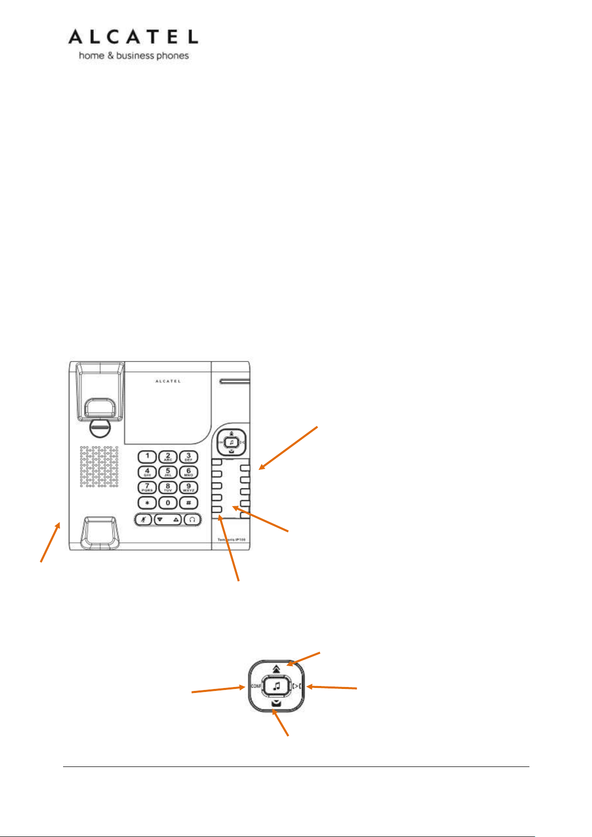
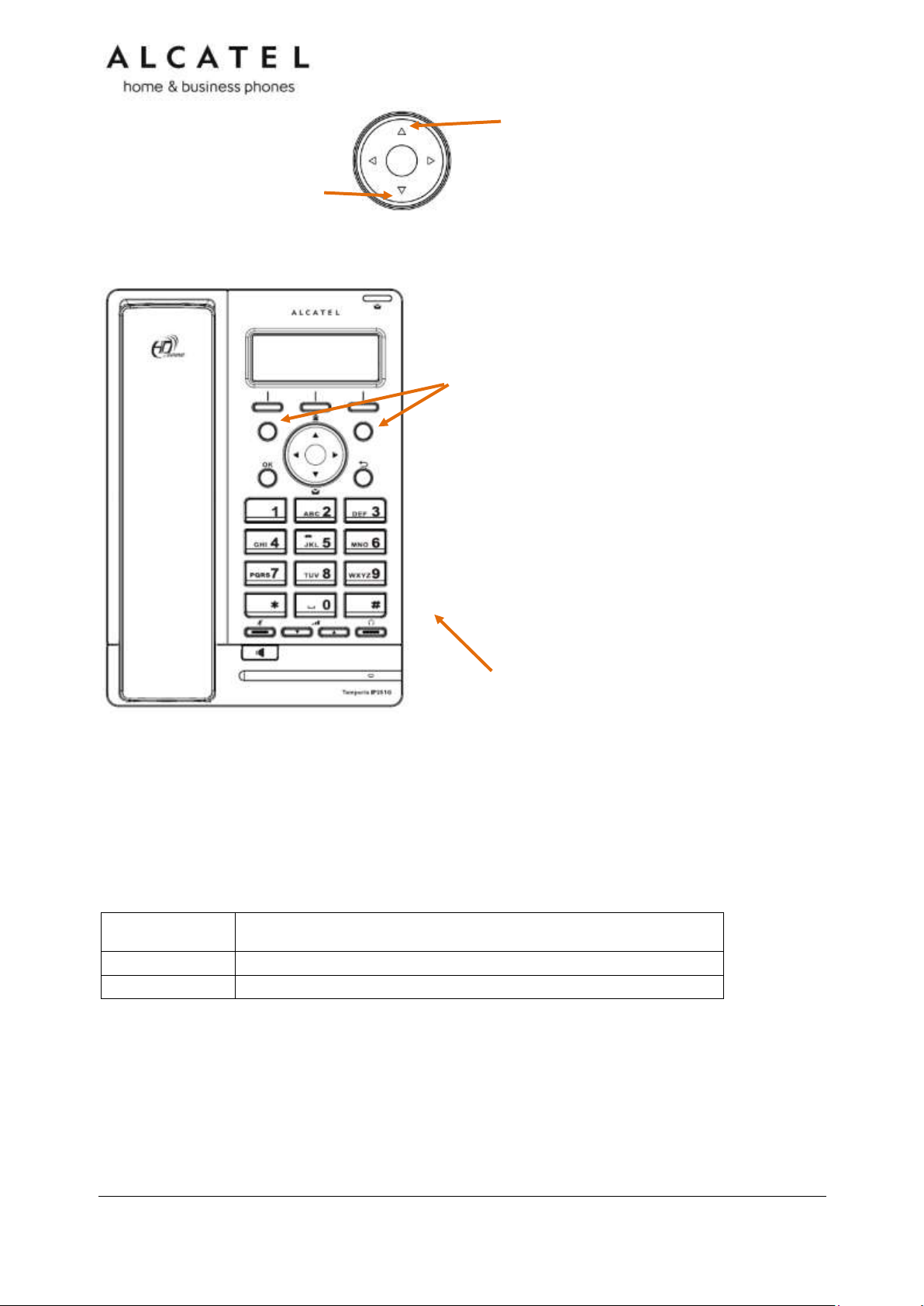
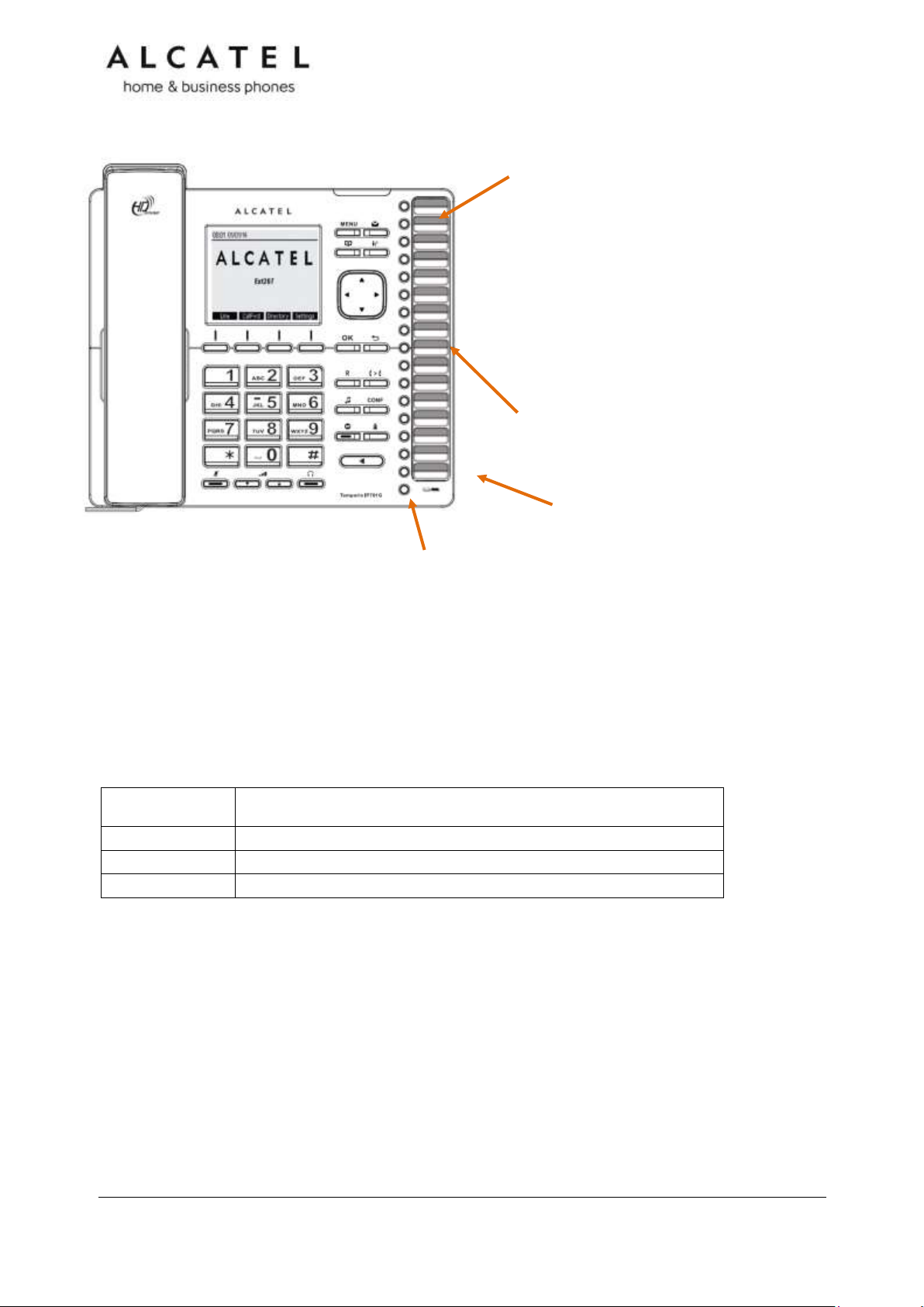
Programmable keys
Can be programmed to perform various functions or access
various features.
For example:
Press to access a line to make a call
Press to dial a monitored extension or a
quick-dial number
Press to answer a ringing call on any line
or monitored extension
Directory card
To write names on the directory card, pull out the directory card
from under the plastic cover.
A fill-in printable template is available at extranet.alcatelbusiness.com
Access F11 To F20
Press F5 to switch to the second possible value of a programmable key.
Note: This is the default setting. You can configure F5 to perform other
functions
RJ9 Corded headset input (on side)
Conference
Press to initiate a conference
with a new call, or to set up a
conference with two already
established calls
Redial
Press to redial last called number
Voicemail
Press to call to your Voicemail
Transfer
Press to initiate a call transfer
towards a new call, or to bridge two
already established calls
Temporis IP100
Temporis IP100 is an entry-level business phone. Its features include:
On hook dialing, headset, hold and mute
1 sip registration
2 active SIP sessions
3-way conferencing, N-way network conferencing
10 dual-function programmable keys, 5 with bicolor led and 2 pages
10 speed dial numbers (long press dial keypad)
Message waiting alert LED
Single 10/100 Mbps Ethernet ports
Power over Ethernet
100-entry Call Log and downloadable local phonebook accessible from WUI
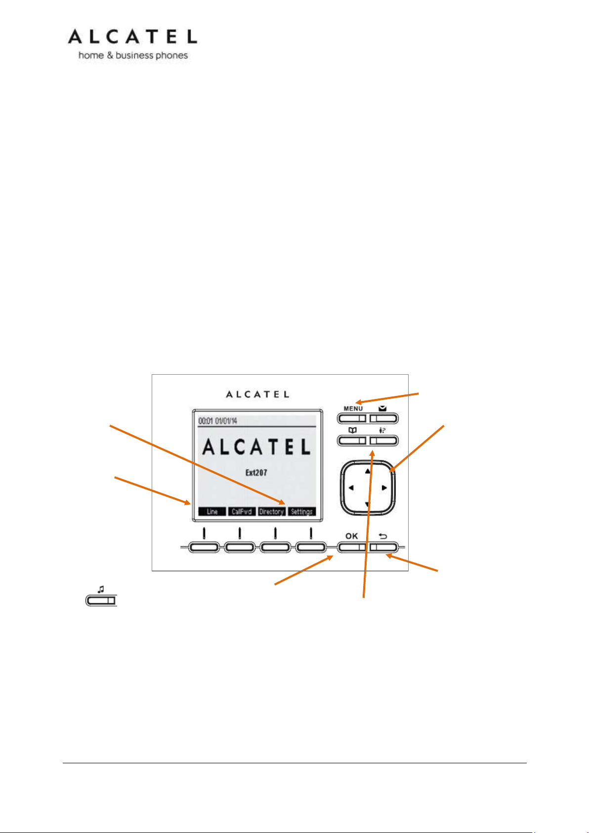
Quick reference guide
The controls you will need to use to manage the phone and external features that are
relevant to installation and configuration are described below.
Business IP Range Administration and Provisioning Guide ed 2.2 9/247
Page 10

Purpose
Command
Remarks
IP address
announcement
*123456#
Static IP
configuration
*782842#x*x*x*x#y*y*y*y#z*z*z*z#
x*x*x*x = IP address
y*y*y*y = subnet mask
z*z*z*z = default gateway
Switch VLAN off
* 7 8 2 8 4 3 # 0 # #
Switch VLAN ON
plus edit VID
* 7 8 2 8 4 3 # 1 # ???? #
???? = VLAN ID
Key Number
Setting
1
Line 1*
2
Line 1
3
Quick dial
4
Quick dial
5
Access to F11-F20
6-14
Quick dial
15
Access to F11-F20
16-20
Quick dial
The following table includes some useful star codes to help you quickly configure IP100. To
invoke a command simply dial the sequence in on-hook mode.
Programmable Keys
The table below lists the default settings for the programmable keys. The key assignments
on your phone may be different. Some keys may be programmed as Quick Dial keys, or
access to other functions like Call forward, for example.
Keys are numbered from top left to bottom left, and then top right to bottom right. Note
keys 11 to 20 are virtual, ie they are accessed when key 5 is configured as Access to F11F20
* You can assign more than one key to a certain type of function. For example, you can
configure keys 1 and 2 to access Line 1. Label the keys appropriately for deskset users after
configuration. A printable fill-in template is available for download at extranet.alcatelbusiness.com
To assign functions to programmable keys, please see Programmable Function Keys on
page 118.
Business IP Range Administration and Provisioning Guide ed 2.2 10/247
Page 11
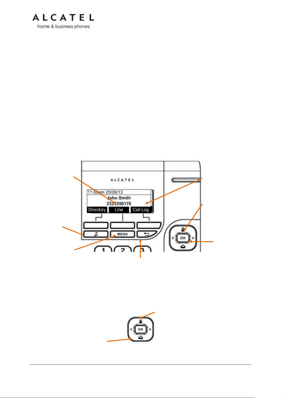
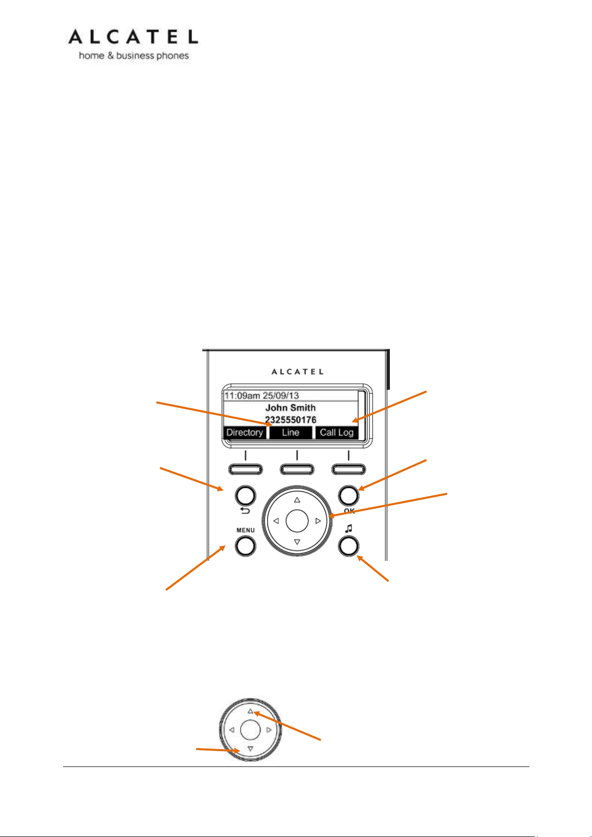
MENU
Press to enter the menu.
CANCEL
While in a menu, press to cancel an
operation and exit the menu.
In idle mode, long press to reboot
the phone
OK
Press to select a menu item or
save an entry or setting.
NAVIGATION KEY
While in menus, press
or to scroll through the
menu, highlight items or
change settings.
Press or to
navigate through softkey
pages
While entering names or
numbers, press or to
move the cursor left or
right.
Line
Press to change
dial-out account
(shown if second
sip account is
registered only)
Hold key
In conversation, press to
place active call on hold.
In idle mode, press to
quickly access Network
Status menu
Call Log
Press to quickly access Call Log
menu
Redial
Press to access redial list
Voicemail
Press to access Voicemail
menu
Temporis IP150 (M)
Temporis IP150 is an entry level business phone. Its features include:
2.5-inch backlit Liquid Crystal Display
Speakerphone, Headset, Hold and Mute
Up to 2 SIP Registrations
Up to 6 active SIP sessions
3-way conferencing, N-way network conferencing
10 dual-function programmable keys, 5 with bicolor led
Customizable softkeys and logo
10 speed dial numbers (long press dial keypad)
Message Waiting alert LED
Dual 10/100 Mbps Ethernet ports with Power over Ethernet
100-entry Call Log, downloadable local and LDAP phonebooks
While Temporis IP150 supports PoE, Temporis IP150M does not and requires a power
supply to work. Apart from this difference, they are exactly the same in terms of features,
firmware and configuration.
Quick reference guide
The controls you will need to use to configure the phone manually are described below.
Navigation key also provides shortcuts to the following functions in idle mode:
Business IP Range Administration and Provisioning Guide ed 2.2 11/247
Page 12
Key Number
Setting
1
Line 1*
2
Line 1
3
Quick dial
4
Quick dial
5
Access to F11-F20
6-14
Quick dial
15
Access to F11-F20
16-20
Quick dial
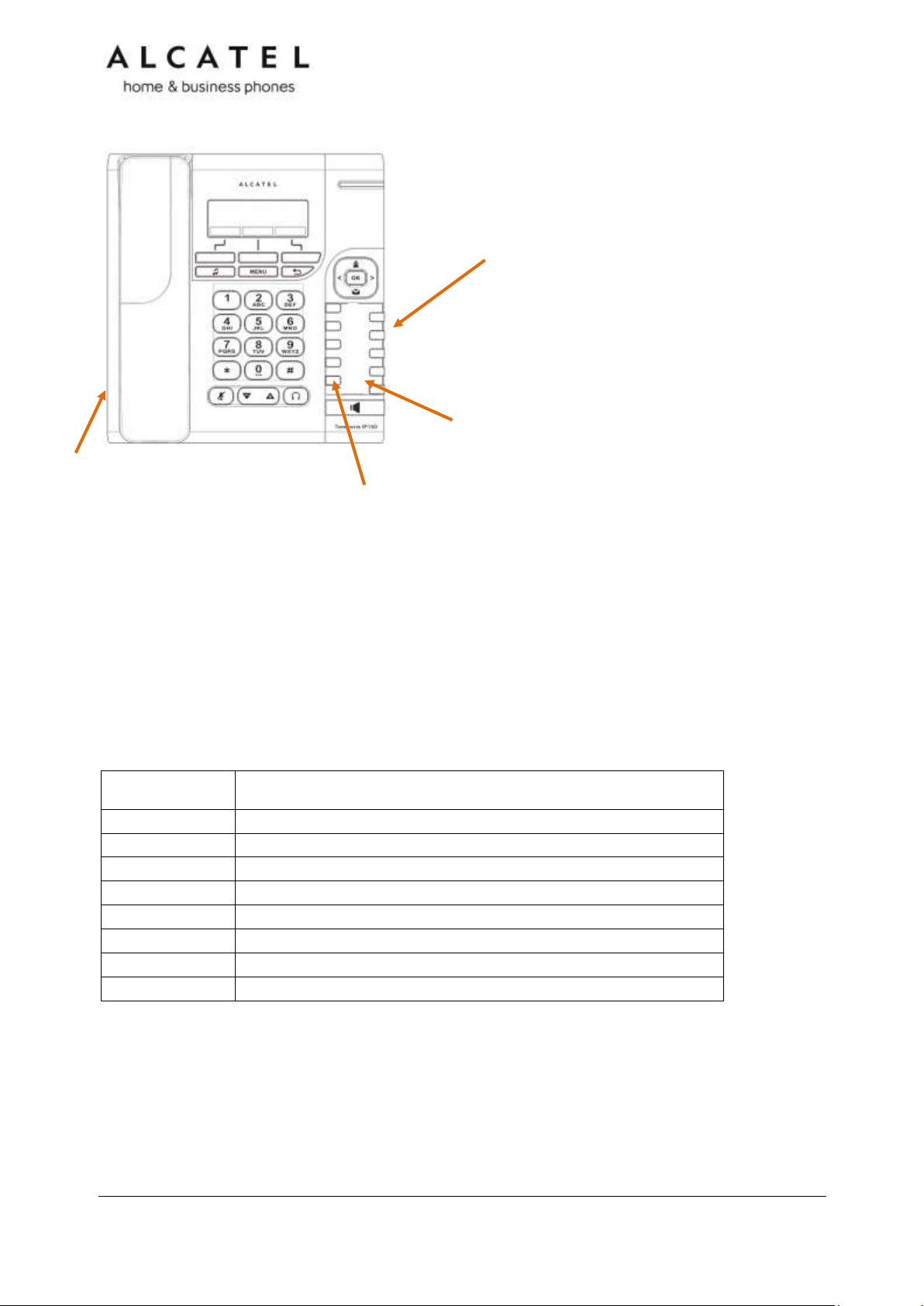
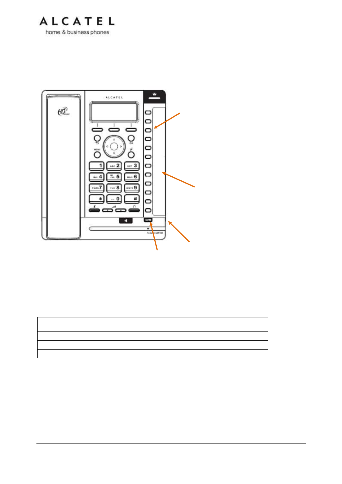
Programmable keys
Can be programmed to perform various functions or access
various features.
For example:
Press to access a line to make a call
Press to dial a monitored extension or a quick-
dial number
Press to answer a ringing call on any line or
monitored extension
Directory card
To write names on the directory card, pull out the directory card
from under the plastic cover.
A fill-in printable template is available at extranet.alcatelbusiness.com
Access F11 To F20
Press F5 to switch to the second possible value of a programmable key.
Note: This is the default setting. You can configure F5 to perform other
functions
RJ9 Corded headset input (on side)
The deskset external features that are relevant to installation and configuration are
described below.
Programmable Keys
The table below lists the default settings for the programmable keys. The key assignments
on your phone may be different. Some keys may be programmed as Quick Dial keys, or
access to other functions like Call forward, for example.
Keys are numbered from top left to bottom left, and then top right to bottom right. Note
keys 11 to 20 are virtual, ie they are accessed when key 5 is configured as Access to F11F20
* You can assign more than one key to a certain type of function. For example, you can
configure keys 1 and 2 to access Line 1, and keys 3 and 4 to access Line 2. Label the keys
appropriately for deskset users after configuration. A printable fill-in template is available
for download at extranet.alcatel-business.com
To assign functions to programmable keys, please see Programmable Function Keys on
page 118
Business IP Range Administration and Provisioning Guide ed 2.2 12/247
Page 13

Temporis IP151
Temporis IP151 is an entry level business phone. Its features include:
2.5-inch backlit Liquid Crystal Display
Speakerphone, Headset, Hold and Mute
Up to 2 SIP Registrations
Up to 6 active SIP sessions
3-way conferencing, N-way network conferencing
10 dual-function programmable keys, 5 with bicolor led
Customizable softkeys, hardkeys, logo, ringtone and language, XML browser, action urls
10 speed dial numbers (long press dial keypad)
Message Waiting alert LED
Dual 10/100 Mbps Ethernet ports with Power over Ethernet
IPv6 support
200-entry Call Log, 1000-entry downloadable local phonebook, LDAP
Quick reference guide
The controls you will need to use to configure the phone manually are the same as in
IP150. Please refer to Temporis IP150 Quick reference guide chapter on page 11.
Programmable Keys
Usage and default values are the same as in IP150. Please refer to Temporis IP150
Programmable Keys chapter on page 12.
Business IP Range Administration and Provisioning Guide ed 2.2 13/247
Page 14
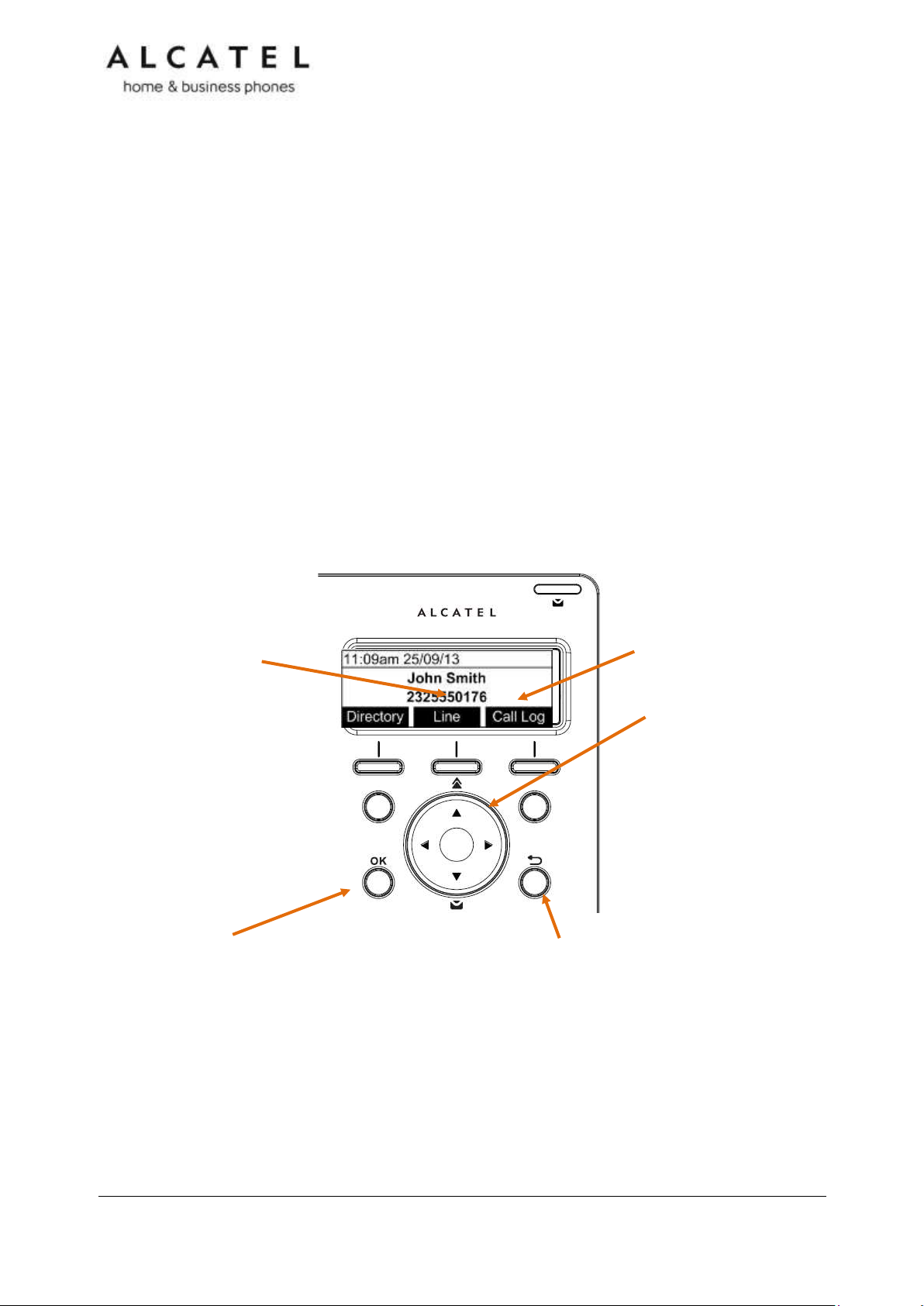
OK
Press to enter the menu, to
select a menu item or save
an entry or setting.
CANCEL
While in a menu, press to
cancel an operation and exit
the menu.
In idle mode, press to see
Network status, or press
once and then long press to
reboot the phone
NAVIGATION KEY
While in menus, press
or to scroll through the
menu, highlight items or
change settings.
Press or to
navigate through softkey
pages
While entering names or
numbers, press or to
move the cursor left or
right.
Line
Press to change
dial-out account
(shown if second
sip account is
registered only)
Call Log
Press to quickly access call
lists menu
Temporis IP251G
Temporis IP251G is an entry level business phone. Its features include:
2.5-inch backlit Liquid Crystal Display
Speakerphone, Headset, Hold and Mute
Up to 2 SIP Registrations
Up to 6 active SIP sessions
3-way conferencing, N-way network conferencing
2 programmable keys with bicolor led backlight
Customizable softkeys, hardkeys, logo, ringtone and language, XML browser, action urls
10 speed dial numbers (long press dial keypad)
Message Waiting alert LED
Dual 10/100/1000 Mbps Ethernet ports with Power over Ethernet
IPv6 support
200-entry Call Log, 1000-entry downloadable local phonebook, LDAP
Quick reference guide
The controls you will need to use to configure the phone manually are described below.
Navigation key also provides shortcuts to the following functions in idle mode:
Business IP Range Administration and Provisioning Guide ed 2.2 14/247
Page 15
Key Number
Setting
1
Line 1*
2
Line 1
Programmable keys with backlight
Can be programmed to perform various functions or access
various features.
For example:
Press to access a line to make a call
Press to dial a monitored extension or a quick-dial number
Press to answer a ringing call on any line or monitored
extension
See also Programmable Keys on page 15.
2.5mm corded headset input (on
side)
Redial
Press to access redial list
Voicemail
Press to access Voicemail
menu
The deskset external features that are relevant to installation and configuration are
described below.
Programmable Keys
The table below lists the default settings for the programmable keys. The key assignments
on your phone may be different. Some keys may be programmed as Quick Dial keys, or
access to other functions like Call forward, for example.
* You can assign more than one key to a certain type of function. For example, you can
configure keys 1 and 2 to access Line 1, or one of the keys to access Line 2.
Business IP Range Administration and Provisioning Guide ed 2.2 15/247
Page 16
MENU
Press to enter the menu.
CANCEL
While in a menu, press to
cancel an operation and exit
the menu.
In idle mode, long press to
reboot the phone
OK
Press to select a menu item or
save an entry or setting.
NAVIGATION KEY
While in menus, press
or to scroll through the
menu, highlight items or
change settings.
Press or to
navigate through softkey
pages
While entering names or
numbers, press or to
move the cursor left or
right.
Line
Press to change
dial-out account
(shown if second
sip account is
registered only)
Hold key
In conversation, press to
place active call on hold.
In idle mode, press to
quickly access Network
Status menu
Call Log
Press to quickly access call
lists menu
Redial
Press to access redial list
Voicemail
Press to access Voicemail
menu
Temporis IP300
Temporis IP300 is a mid-range business phone with cordless capabilities. Its features
include:
2.5-inch backlit Liquid Crystal Display
Speakerphone, Headset, Hold and Mute
Up to 3 SIP Registrations
Up to 6 active SIP sessions
3-way conferencing, N-way network conferencing
IP70H DECT headset and IP15 DECT handset support
12 dual-function programmable keys with bicolor led
Customizable softkeys and logo
10 speed dial numbers (long press dial keypad)
Message Waiting alert LED
Dual 10/100 Mbps Ethernet ports with Power over Ethernet
200-entry Call Log, downloadable local and LDAP phonebooks
Quick reference guide
The controls you will need to use to configure the phone manually are described below.
Navigation key also provides shortcuts to the following functions in idle mode:
Business IP Range Administration and Provisioning Guide ed 2.2 16/247
Page 17
Key Number
Setting
1
Line 1*
2
Line 1
3-12
Quick dial
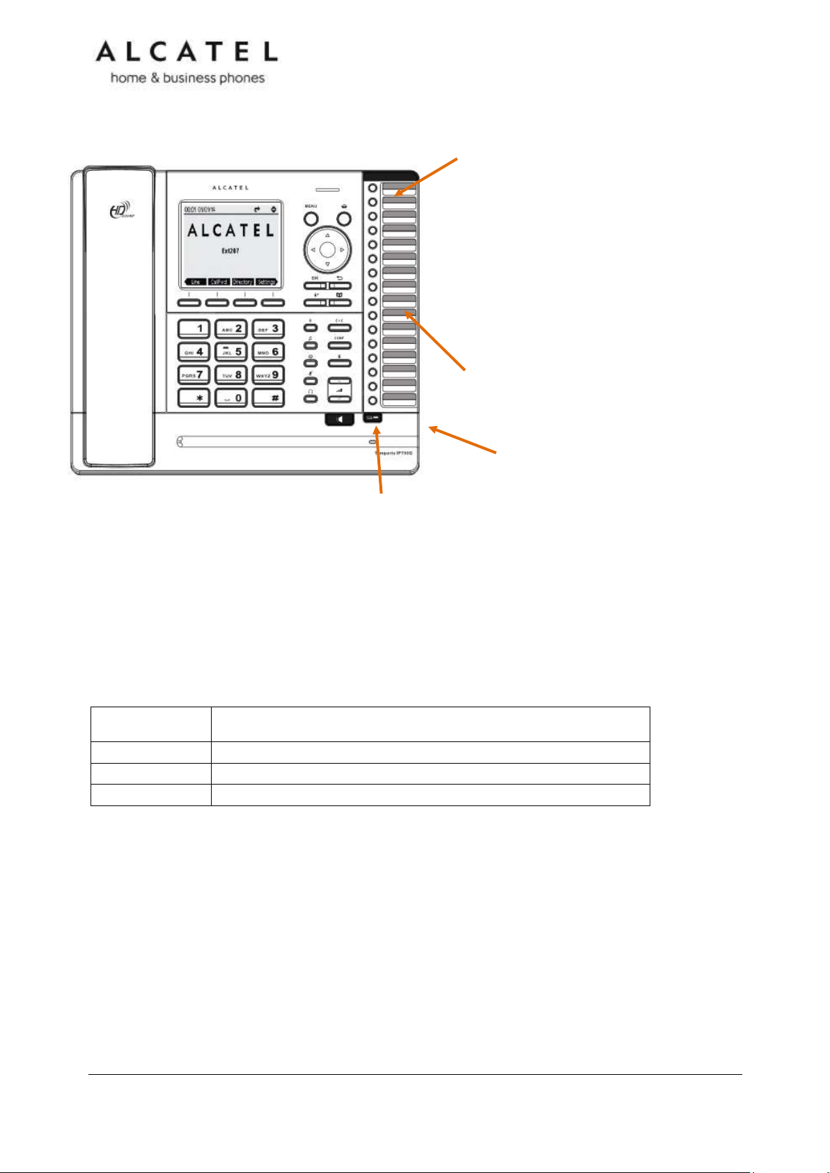
Programmable keys
Can be programmed to perform various functions or access
various features.
For example:
Press to access a line to make a call
Press to dial a monitored extension or a quick-dial number
Press to answer a ringing call on any line or monitored
extension
See also Programmable Keys on page 15.
Directory card
To write names on the directory card, pull out the
directory card from under the plastic cover.
A fill-in printable template is available at
extranet.alcatel-business.com
Access F13 to F24
Press this key to switch to the second possible value of a programmable
key.
2.5mm corded headset input (on
side)
The deskset external features that are relevant to installation and configuration are
described below.
Programmable Keys
The table below lists the default settings for the programmable keys. The key assignments
on your phone may be different. Some keys may be programmed as Quick Dial keys, or
access to other functions like Call forward, for example.
* You can assign more than one key to a certain type of function. For example, you can
configure keys 1 and 2 to access Line 1, and keys 3 and 4 to access Line 2. Label the keys
appropriately for deskset users after configuration.
Business IP Range Administration and Provisioning Guide ed 2.2 17/247
Page 18

Temporis IP301G
Temporis IP301G is a mid-range business phone with cordless capabilities. Its features
include:
2.5-inch backlit Liquid Crystal Display
Speakerphone, Headset, Hold and Mute
Up to 3 SIP Registrations
Up to 6 active SIP sessions
3-way conferencing, N-way network conferencing
IP70H DECT headset and IP15 DECT handset support
12 dual-function programmable keys with bicolor led
Customizable softkeys, hardkeys, logo and ringtone, XML browser, action urls
10 speed dial numbers (long press dial keypad)
Message Waiting alert LED
Dual 10/100/1000 Mbps Ethernet ports with Power over Ethernet
IPv6 support
200-entry Call Log, 1000-entry downloadable local phonebook, LDAP
Quick reference guide
The controls you will need to use to configure the phone manually are the same as for
IP300. Please check Temporis IP300 Quick reference guide on page 14.
Programmable Keys
Usage and default values are the same as in IP300. Please refer to Temporis IP300
Programmable Keys chapter on page 15.
Business IP Range Administration and Provisioning Guide ed 2.2 18/247
Page 19

MENU
Press to enter the menu.
CANCEL
While in a menu, press to
cancel an operation and exit
the menu.
In idle mode, long press to
reboot the phone
OK
Press to select
a menu item or
save an entry
or setting.
NAVIGATION KEY
While in menus, press
or to scroll through the
menu, highlight items or
change settings.
Press or to
navigate through softkey
pages
While entering names or
numbers, press or to
move the cursor left or
right.
Line
Press to change
dial-out account
(shown if more
than one sip
account is
registered only)
Hold key
In conversation, press to
place active call on hold.
In idle mode, press to
quickly access Network
Status menu
Call Log
Press to quickly
access call lists
Settings
Press to access
Settings menu
Temporis IP700G
Temporis IP700G is a feature business phone with cordless capabilities. Its features include:
3.5-inch backlit Liquid Crystal Display
Speakerphone, Headset, Hold and Mute
Up to 6 SIP Registrations
Up to 6 active SIP sessions
3-way conferencing, N-way network conferencing
IP70H DECT headset and IP15 DECT handset support
16 dual-function programmable keys with bicolor led
Customizable softkeys and logo
10 speed dial numbers (long press dial keypad)
Message Waiting alert LED
Dual 10/100/1000 Mbps Ethernet ports
Power over Ethernet enabled
200-entry Call Log, downloadable local and LDAP phonebooks
Quick reference guide
The controls you will need to use to configure the phone manually are described below.
Business IP Range Administration and Provisioning Guide ed 2.2 19/247
Page 20
Key Number
Setting
1
Line 1*
2
Line 1
3-16
Quick dial
Programmable keys
Can be programmed to perform various functions or access
various features.
For example:
Press to access a line to make a call
Press to dial a monitored extension or a quick-dial number
Press to answer a ringing call on any line or monitored
extension
See also Programmable Keys on page 20.
Directory card
To write names on the directory card, pull out the
directory card from under the plastic cover.
A fill-in printable template is available at
extranet.alcatel-business.com
Access F13 to F24
Press this key to switch to the second possible value of a programmable
key.
2.5mm corded headset input (on
side)
The deskset external features that are relevant to installation and configuration are
described below.
Programmable Keys
The table below lists the default settings for the programmable keys. The key assignments
on your phone may be different. Some keys may be programmed as Quick Dial keys, or
access to other functions like Call forward, for example.
* You can assign more than one key to a certain type of function. For example, you can
configure keys 1 and 2 to access Line 1, and keys 3 and 4 to access Line 2. Label the keys
appropriately for deskset users after configuration.
Business IP Range Administration and Provisioning Guide ed 2.2 20/247
Page 21
MENU
Press to enter the menu.
CANCEL
While in a menu, press to
cancel an operation and exit
the menu.
In idle mode, long press to
reboot the phone
OK
Press to select
a menu item or
save an entry
or setting.
NAVIGATION KEY
While in menus, press
or to scroll through the
menu, highlight items or
change settings.
Press or to
navigate through softkey
pages
While entering names or
numbers, press or to
move the cursor left or
right.
Line
Press to change
dial-out account
(shown if more
than one sip
account is
registered only)
Hold key
In conversation, press to
place active call on hold.
In idle mode, press to
quickly access Network
Status menu
Call Log
Press to quickly
access call lists
menu
Settings
Press to access
Settings menu
Temporis IP701G
Temporis IP701G is a feature business phone with cordless capabilities. Its features include:
3.5-inch backlit Liquid Crystal Display
Speakerphone, Headset, Hold and Mute
Up to 6 SIP Registrations
Up to 6 active SIP sessions
3-way conferencing, N-way network conferencing
IP70H DECT headset and IP15 DECT handset support
16 dual-function programmable keys with bicolor led
Customizable softkeys, hardkeys, logo and ringtone, XML browser, action urls
10 speed dial numbers (long press dial keypad)
Message Waiting alert LED
Dual 10/100/1000 Mbps Ethernet ports with Power over Ethernet
IPv6 support
200-entry Call Log, 1000-entry downloadable local phonebook, LDAP
Quick reference guide
The controls you will need to use to configure the phone manually are described below.
Business IP Range Administration and Provisioning Guide ed 2.2 21/247
Page 22
Key Number
Setting
1
Line 1*
2
Line 1
3-16
Quick dial
Programmable keys
Can be programmed to perform various functions or access
various features.
For example:
Press to access a line to make a call
Press to dial a monitored extension or a quick-dial number
Press to answer a ringing call on any line or monitored
extension
See also Programmable Keys on page 20.
Directory card
To write names on the directory card, pull out the
directory card from under the plastic cover.
A fill-in printable template is available at
extranet.alcatel-business.com
Access F13 to F24
Press this key to switch to the second possible value of a programmable
key.
2.5mm corded headset input (on
side)
The deskset external features that are relevant to installation and configuration are
described below.
Programmable Keys
The table below lists the default settings for the programmable keys. The key assignments
on your phone may be different. Some keys may be programmed as Quick Dial keys, or
access to other functions like Call forward, for example.
* You can assign more than one key to a certain type of function. For example, you can
configure keys 1 and 2 to access Line 1, and keys 3 and 4 to access Line 2. Label the keys
appropriately for deskset users after configuration.
Business IP Range Administration and Provisioning Guide ed 2.2 22/247
Page 23
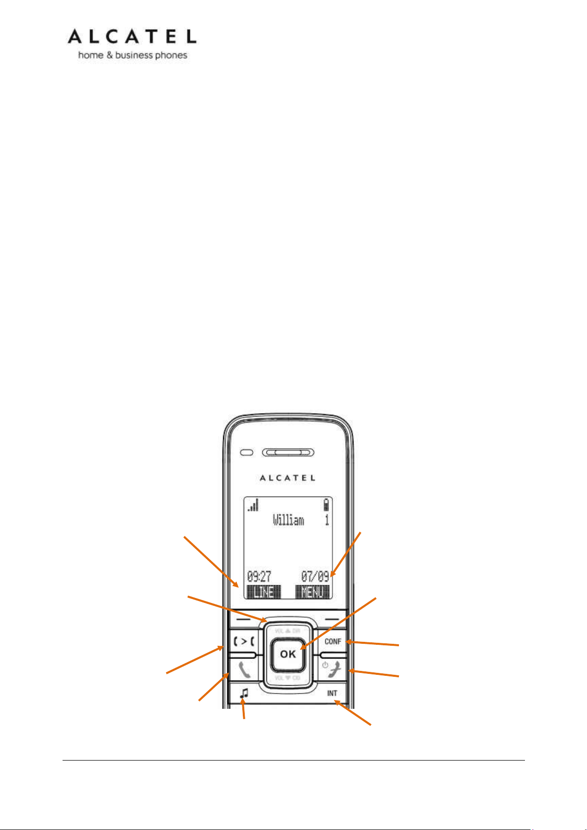
Line
Press left softkey in idle
mode to select dial-out
account
MENU
Press right softkey in idle mode
to enter the menu.
OK
Press to select a menu
item, display available
options, toggle among two
options or save an entry or
CONF
Press to start a 3 way call
Transfer
Press to start a call transfer
Talk
Press to
answer or
start a call
Call Hold
Press to put active call
on hold
Talk off/Power
Press to release a call.
Or to switch on/off
(long press)
Intercom
Press to start an internal call to
other handsets
NAVIGATION KEY
While in menus, press or to
scroll through the menu,
highlight items or change
settings. While entering names or
numbers, press or to move
the cursor left or right.
Alcatel IP2015/IP2115
Alcatel IP2015/IP2115 are multiline multi-handset IP DECT systems. Basic package includes
one base and one handset. IP2015/IP2115 features include:
Out-of-sight, wall mountable, PoE enabled base station
Up to 6 independent SIP Registrations
Up to 6 IP15 handsets supported per base, with over-the air sw upgrade (SUOTA)
Up to 4 concurrent wideband calls per base
3-way conferencing, N-way network conferencing
Shared and LDAP phonebooks
10/100 Mbps Ethernet port
IPv6 support (IP2115 only)
As for the IP15 handset:
1.9-inch backlit Liquid Crystal Display
Wideband audio, hands free
Headset jack and belt clip
10 speed dial numbers (long press dial keypad)
Message Waiting alert LED
Access to local, shared and LDAP phonebooks
Easy access to business functions
Quick reference guide
The controls you will need to use to configure the phone manually are described below.
Business IP Range Administration and Provisioning Guide ed 2.2 23/247
Page 24
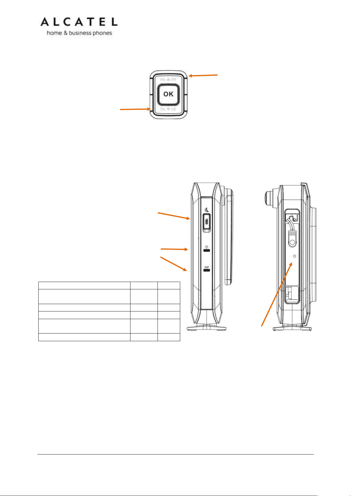
Status
Power
VoIP
Connected to router and IP
address assigned
ON
IP address not available
Flash
All accounts registered
ON
At least one active account
unregistered
OFF
DECT registration mode
Flash
Flash
DIR/VOL +
In idle mode press to quickly access
Contacts menu
When in a call press to increase
received audio volume
At incoming call press to increase
ringer level
CID/VOL -
In idle mode press to quickly
access Call Logs menu
When in a call press to
decrease received audio
volume
At incoming call press to
decrease ringer level
RESET
Press with a paper clip or sharp
object to restore the unit to its
default settings.
Paging/Registration button
Press to locate all registered
handsets.
Long press to set the base unit
into DECT registration mode
Power and VoIP LEDs
Status indication is as follows:
Although there are often dedicated menu items, navigation key also provides shortcuts to
the following functions:
The elements of the base unit you need to consider are the following:
Business IP Range Administration and Provisioning Guide ed 2.2 24/247
Page 25

Line
Press to change dial-out
account (shown if more
than one sip account is
registered only)
PC SPK
Once connected to your PC via USB,
press to use IP1850 as audio device
with your favorite application:
Skype, Lync, etc
Visual indicator (4)
Check the table on
next page for different
LED color and cadence
meaning
MENU
Press to enter the menu.
OK
Press to select a menu item
or save an entry or setting.
HOLD
In conversation, press to
place active call on hold.
CANCEL
While in a menu, press to
cancel an operation and exit
the menu.
MUTE
In conversation, press to
disable all microphones.
Press again to enable.
Talk ON/OFF
Press to launch or answer a
call. Press again to release
a call.
NAVIGATION KEY
While in menus, press or
to scroll through the menu,
highlight items or change
settings.
Press or to navigate
through softkey pages
While entering names or
numbers, press or to
move the cursor left or right.
Conference IP1850
Conference IP1850 is an advanced audioconference device. Its features include:
Wideband, high power speaker
2 embedded microphones
4 detachable wireless microphones with built-in charging cradle
2.5-inch backlit Liquid Crystal Display
Up to 3 SIP Registrations
Up to 6 active SIP sessions
3-way conferencing, N-way network conferencing, hold, mute, transfer
USB connector for PC audio device mode
Customizable softkeys and logo
10 speed dial numbers (long press dial keypad)
Message Waiting alert LED
10/100 Mbps Ethernet ports
Power injector
200-entry Call Log, local and LDAP phonebooks
Quick reference guide
The controls you will need to use to configure the phone manually are described below.
Business IP Range Administration and Provisioning Guide ed 2.2 25/247
Page 26
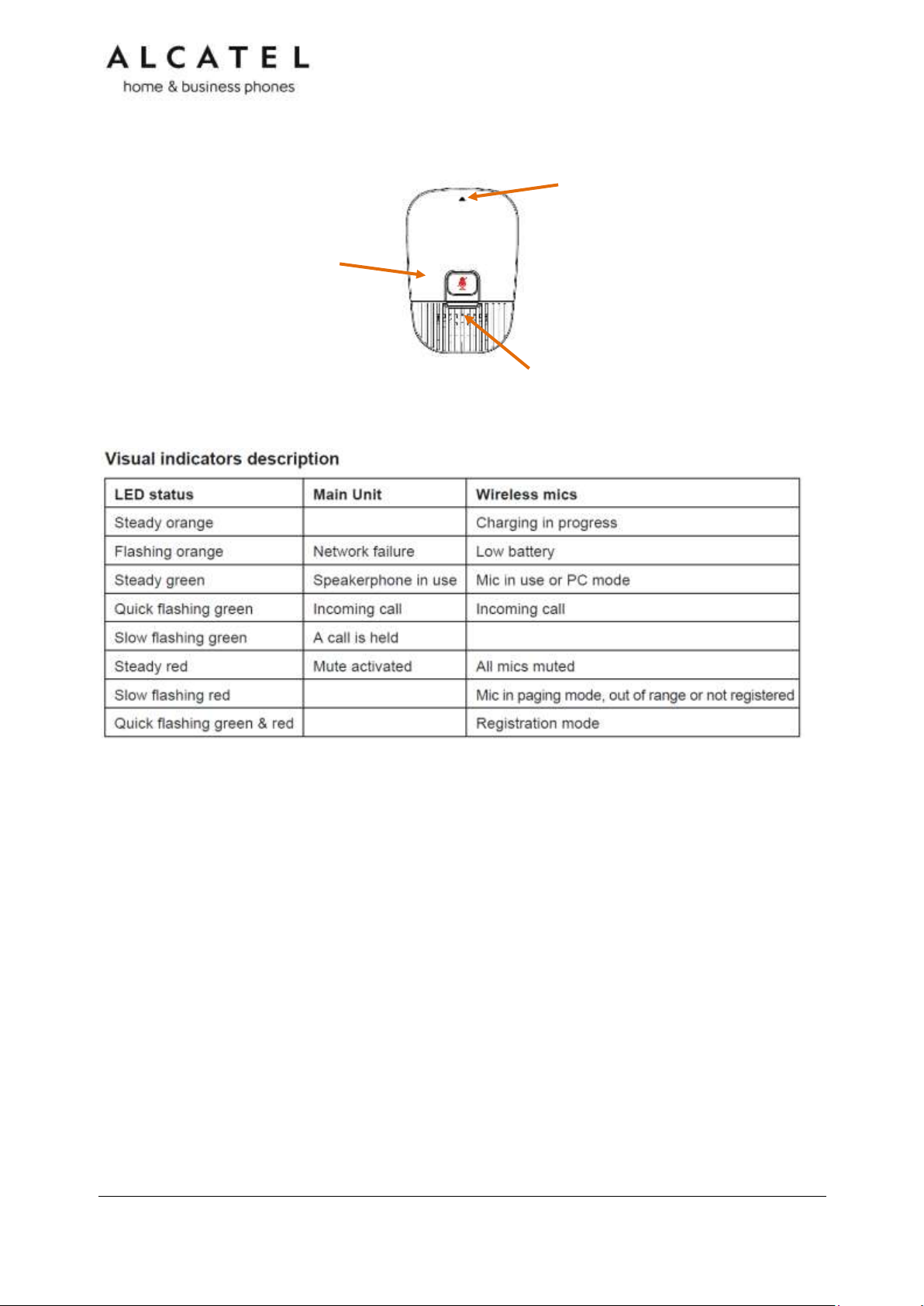
Visual indicator
Check the table below for
color/ cadence meaning
MUTE
In conversation, press to
temporarily deactivate
(mute) all microphones.
Press again to enable
(unmute).
Remove and activate mic
Push gently on the arrow area to remove
the microphone from its cradle.
Please note wireless mics are deactivated
while on their cradle. For best user
experience, if users are located at or
farther than 1m from the main unit, it is
recommended to activate and use these
mics by detaching them from their cradle.
On the wireless microphones you have the following elements:
Business IP Range Administration and Provisioning Guide ed 2.2 26/247
Page 27

Network Requirements
A switched network topology is recommended for your LAN (using standard 10/100 or
10/100/1000 Ethernet switches).
The office LAN infrastructure should use Cat.-5 (or better) cable for 10/100, and Cat.-6 for
10/100/1000.
The LAN connections to the devices(s) should all be wired. However, wireless connections to
other devices (such as laptops) in your office will not impede performance.
All devices must reside on a single subnet. A DHCP server is recommended and must be on
the same subnet as the devices so that IP addresses can be auto-assigned. In most cases,
your network router will have a Dynamic Host Configuration Protocol (DHCP) server that will
automatically assign IP addresses to clients. By default, the phone has DHCP enabled for
automatic IP address assignment.
If no DHCP server is present, you can assign static IPs to devices. If you do not have a
DHCP server or do not manually assign static IPs, you will not be able to access the WebUI
and/or enable automatic time updates from an NTP server.
Unless you want to manually set the system clock and manually or locally upgrade
software, an Internet connection to the LAN is required.
A DNS server is recommended to resolve the path to the Internet and to a server for
firmware and configuration updates.
If necessary, the system administrator can also download upgrade files and use the WebUI
to update the device firmware and/or configuration settings manually.
For users whose computers require a GigE Ethernet frame rate (a gigabit per second), use
either IP700G phone or separate Ethernet connections for the deskset and the computer.
Business IP Range Administration and Provisioning Guide ed 2.2 27/247
Page 28
Installation
This section assumes that your network infrastructure is established and that your hosted
IP PBX service has been ordered and configured for your location.
Install the phone close to a router or network switch. You can power the phone using Power
over Ethernet or the power adapter/injector (not supplied for all models, see part check
list). If you are not using PoE, install the phone near a power outlet not controlled by a wall
switch. The phone can be placed on a flat surface or vertically mounted on the wall.
For customer service or product information, visit our website at extranet.alcatelbusiness.com.
Avoid placing the deskset too close to:
Communication devices such as television sets, DVD players, or other cordless telephones.
Excessive heat sources.
Noise sources such as a window with traffic outside, motors, microwave ovens,
refrigerators, or fluorescent lighting.
Excessive dust sources such as a workshop or garage.
Excessive moisture.
Extremely low temperature.
Mechanical vibration or shock such as on top of a washing machine or work bench.
Figure 1: Temporis IP300 Installation Example
Temporis IP100/IP150/IP151 installation
To install the phone:
1. If you plan to place the phone on a flat surface, you can use one of the two available
positions depending on the work angle you wish to have, ie with or without the
detachable foot stand. To assemble the stand line up the tabs on the stand (marked
with triangles) with the slots on the rear of the phone as shown in the picture
Plug the end of the coiled handset cord into the Handset jack at the left side of the
phone.
2. Plug one end of the Ethernet cable into the Ethernet port at the back of the console, and
plug the other end of the cable into your network router or switch.
Business IP Range Administration and Provisioning Guide ed 2.2 28/247
Page 29

NOTE: You may need to use a network switch connected to your router if your router
does not have sufficient ports for the number of phones you want to install. If you use a
network switch, connect the phone to the switch instead of the router in the previous
step.
3. If the deskset is not using power from a PoE-capable network router or switch, or in any
case for an IP150M:
a. Connect the power adapter to the deskset power jack.
b. Plug the power adapter into an electrical outlet not controlled by a wall
switch.
IMPORTANT INFORMATION
1. Use only original power adapters. Contact your distributor to order.
2. The power adapter is intended to be correctly oriented in a vertical or floor mount
position. The prongs are not designed to hold the plug in place if it is plugged into a
ceiling, under-the-table or cabinet outlet.
If there is a networked computer and no extra Ethernet wall ports near the phone, then the
phone and PC can share the same network connection.
To share a network connection with a PC (IP150/IP151 only):
1. Plug a Cat.-5 Ethernet cable into the PC port on the phone.
2. Plug the other end of the Cat.-5 Ethernet cable into your computer’s network port.
If a GigE network is being used, a computer connected through the phone will be limited to
100 Mbits/s. If you require a GigE Ethernet rate, use separate Ethernet connections for the
phone and the computer.
If a PC is connected to your network through a phone, any phone resets and power or
network interruptions will disrupt the PC’s connection to the network.
Business IP Range Administration and Provisioning Guide ed 2.2 29/247
Page 30

To mount the phone on the wall:
1. Disassemble the foot stand
2. Install wall mount fittings and foot stand as displayed:
3. Put the corded handset aside. Use a coin to rotate the handset tab 180 degrees. The
protruding edge holds the corded handset when the phone is mounted on the wall.
4. Connect the network cable(s) and power adapter (if required).
5. Hang the phone using holes on the wall mount fitting part.
Business IP Range Administration and Provisioning Guide ed 2.2 30/247
Page 31

Temporis IP251G/IP300/IP301G/IP701G installation
To install the phone:
1. If you plan to place the phone on a flat surface, you can use one of the two available
positions depending on the work angle you wish to have. To assemble the stand line up
the tabs on the stand (marked with lozenges) with the slots on the rear of the phone as
shown in the picture
Plug the end of the coiled handset cord into the Handset jack at the back of the phone.
2. Plug one end of the Ethernet cable into the Ethernet port at the back of the console, and
plug the other end of the cable into your network router or switch.
NOTE: You may need to use a network switch connected to your router if your router
does not have sufficient ports for the number of phones you want to install. If you use a
network switch, connect the phone to the switch instead of the router in the previous
step.
3. If the deskset is not using power from a PoE-capable network router or switch:
a. Connect the power adapter to the deskset power jack.
b. Plug the power adapter into an electrical outlet not controlled by a wall
switch.
Business IP Range Administration and Provisioning Guide ed 2.2 31/247
Page 32

IMPORTANT INFORMATION
1. Use only original power adapters. Contact your distributor to order.
2. The power adapter is intended to be correctly oriented in a vertical or floor mount
position. The prongs are not designed to hold the plug in place if it is plugged into a
ceiling, under-the-table or cabinet outlet.
If there is a networked computer and no extra Ethernet wall ports near the phone, then the
phone and PC can share the same network connection.
To share a network connection with a PC:
3. Plug a Cat.-5 Ethernet cable into the PC port on the phone.
4. Plug the other end of the Cat.-5 Ethernet cable into your computer’s network port.
For IP300, if a GigE network is being used, a computer connected through the phone will be
limited to 100 Mbits/s. If you require a GigE Ethernet rate, use separate Ethernet
connections for the phone and the computer. This remark is not applicable to IP251G,
IP301G or IP701G, since all of them have a GigE switch.
If a PC is connected to your network through a phone, any phone resets and power or
network interruptions will disrupt the PC’s connection to the network.
To mount the phone on the wall:
1. Put the corded handset aside. Use a coin to rotate the handset tab 180 degrees. The
protruding edge holds the corded handset when the phone is mounted on the wall.
2. Connect the network cable(s) and power adapter (if required).
3. Hang the phone on the wall using wall mount holes.
Business IP Range Administration and Provisioning Guide ed 2.2 32/247
Page 33

Temporis IP700G installation
To install the phone:
1. If you plan to place the phone on a flat surface, you can use one of the multiple
available positions depending on the work angle you wish to have. Simply adjust the
foot stand with the slots on the rear of the phone as shown in the picture
2. Plug the end of the coiled handset cord into the Handset jack at the left hand side of the
phone.
3. Plug one end of the Ethernet cable into the Ethernet port at the back of the console, and
plug the other end of the cable into your network router or switch.
NOTE: You may need to use a network switch connected to your router if your router
does not have sufficient ports for the number of phones you want to install. If you use a
network switch, connect the phone to the switch instead of the router in the previous
step.
4. If the desk set is not using power from a PoE-capable network router or switch:
Business IP Range Administration and Provisioning Guide ed 2.2 33/247
Page 34

a. Connect the power adapter to the deskset power jack.
b. Plug the power adapter into an electrical outlet not controlled by a wall
switch.
IMPORTANT INFORMATION
1. Use only original power adapters. Contact your distributor to order.
2. The power adapter is intended to be correctly oriented in a vertical or floor mount
position. The prongs are not designed to hold the plug in place if it is plugged into a
ceiling, under-the-table or cabinet outlet.
If there is a networked computer and no extra Ethernet wall ports near the phone, then the
phone and PC can share the same network connection.
To share a network connection with a PC:
1. Plug an Ethernet cable into the PC port on the phone.
2. Plug the other end of the Ethernet cable into your computer’s network port.
If a GigE network is being used, make sure Cat.-6 cables are used.
If a PC is connected to your network through a phone, any phone resets and power or
network interruptions will disrupt the PC’s connection to the network.
To mount the phone on the wall:
1. Fold the foot stand as
depicted
2. Assemble the wall
mount accessory
3. Put the corded handset
aside. Use a coin to
rotate the handset tab
180 degrees. The
protruding edge holds
the corded handset
when the phone is
mounted on the wall.
4. Connect the network cable(s) and power adapter
(if required).
5. Hang the phone on the wall using wall mount
holes.
Business IP Range Administration and Provisioning Guide ed 2.2 34/247
Page 35

Alcatel IP2015/IP2115 installation
To install the base:
1. Plug one end of the Ethernet cable into the Ethernet port at the
side of the base, and plug the other end of the cable into your
network router or switch.
NOTE: You may need to use a network switch connected to
your router if your router does not have sufficient ports for the
number of phones you want to install. If you use a network
switch, connect the phone to the switch instead of the router in
the previous step.
2. If the base is not using power from a PoE-capable network
router or switch:
a. Connect the power adapter to the base power jack.
b. Plug the power adapter into an electrical outlet not controlled by a wall
switch.
To mount the base station on the wall :
1. Assemble the wall mount bracket as depicted.
2. Connect the network cable and power adapter (if required).
3. Hang the phone on the wall using wall mount holes.
To install the handset:
1. Connect handset charging cradle to provided adapter. Plug the adaptor to the mains.
2. Insert and connect supplied battery pack into handset
battery compartment.
3. Place the handset on the charger and fully charge the battery for
15 hours
Business IP Range Administration and Provisioning Guide ed 2.2 35/247
Page 36

IMPORTANT INFORMATION
1. Use only supplied power adapters and battery pack.
2. The power adapter is intended to be correctly oriented in a vertical or floor mount
position. The prongs are not designed to hold the plug in place if it is plugged into a
ceiling, under-the-table or cabinet outlet.
Your handset is already subscribed to the base. So if you are installing a system with only
one handset you don’t need to perform any association procedure.
If you acquire additional handsets you will need to follow some simple steps. See Setting up
IP2015/IP2115 with multiple IP15 handsets on page 53.
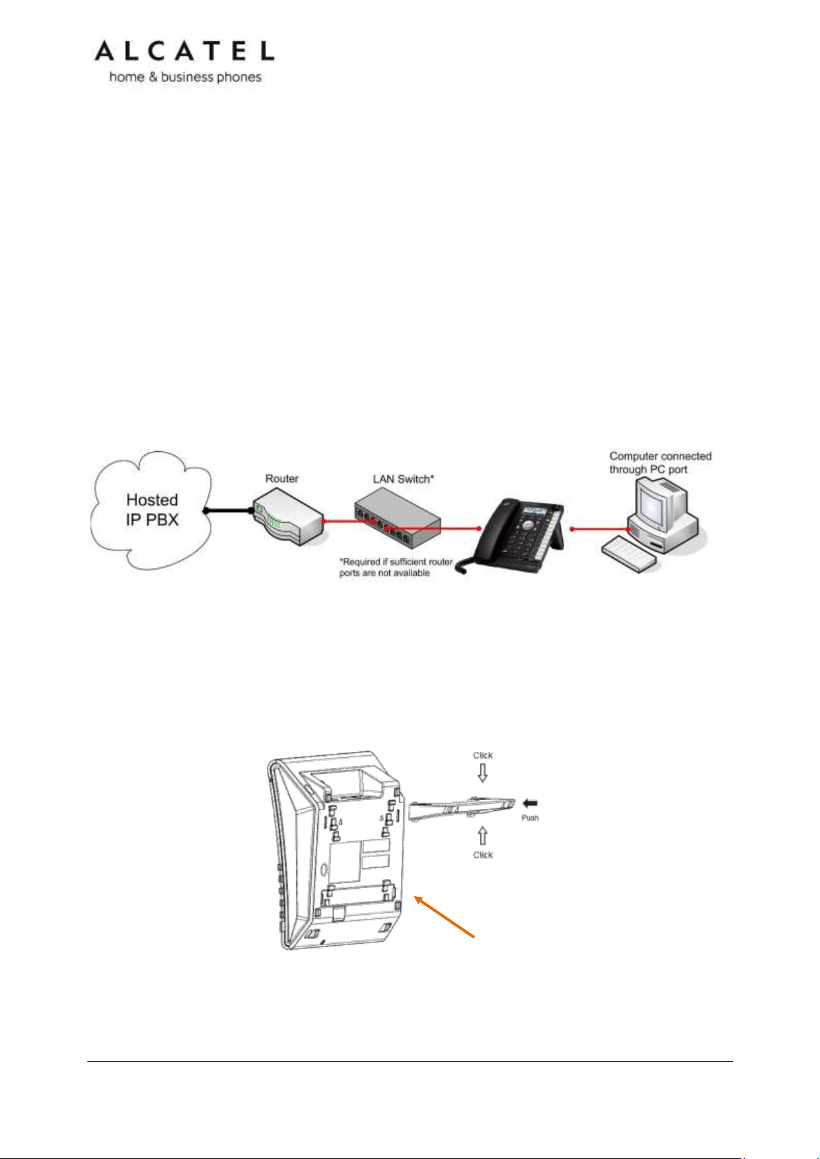
Conference IP1850 installation
To install the main unit:
1. Plug one end of the Cat-5 cable with yellow connectors to the LAN port of your IP1850.
Connect the other end to the “IP1850” port on the supplied power adapter/injector.
2. Plug the second Ethernet cable into the “LAN” port on the power injector, and plug the
other end into your network router or switch.
NOTE: You may need to use a network switch connected to your router if your router
does not have sufficient ports for the number of phones you want to install. If you use a
network switch, connect the phone to the switch instead of the router in the previous step.
3. Connect the power cable onto the power injector, and plug the other end into an
electrical outlet not controlled by a wall switch.
Business IP Range Administration and Provisioning Guide ed 2.2 36/247
Page 37

To install the wireless microphones:
1. For each microphone, activate the battery by pulling away the
plastic tag, or insert the battery into its compartment.
2. Place the microphones on the charging cradles
NOTE: If the microphone unit does not turn on when plastic tag
is removed, take the battery out, reinsert and charge for 8 hours. Wireless mics are
active while detached from main unit only. To get the best of your conference phone, if
you are placed at or farther than 1m from the base please remove mic by pushing on
the arrow at the top of the mic.
IMPORTANT INFORMATION
1. Use only provided power adapter/injector.
2. Use the batteries supplied in the package only. Use of any other type of battery presents
a risk of explosion. Used batteries must be disposed of in compliance with current
environmental protection regulations.
3. The power plug is intended to be correctly oriented in a vertical or floor mount position.
The prongs are not designed to hold the plug in place if it is plugged into a ceiling,
under-the-table or cabinet outlet.
To connect IP1850 to your computer:
1. Plug the micro USB end of the USB cable supplied in the package to the main unit USB
connector as depicted below.
2. Plug the other end into a USB port on your computer
Business IP Range Administration and Provisioning Guide ed 2.2 37/247
Page 38

To associate a new wireless microphone:
Your IP1850 is shipped with all four wireless microphones already associated to the main
unit. In the unlikely event you need to replace any of them, you will find herewith
instructions to associate a new microphone.
1. On the main unit, go to Menu> 3.User settings >4.Wireless microphones
>1.Register
2. Place an unregistered microphone on the cradle
3. IP1850 should indicate the success of the operation.
NOTE: Registration has to be done for one mic at a time. Moreover, you will not be able
to register a new microphone if there are already 4 mics associated to the unit. To
unregister microphones see next paragraph.
To disassociate the wireless microphones from the main unit:
1. On the main unit, go to Menu> 3.User settings >4.Wireless microphones
>2.Deregister
2. All wireless mics will be unregistered from the base. To re-associate them see the
previous paragraph.
To disassociate a wireless microphone without the main unit:
Should you need to delete association information from a wireless microphone without
having access to its former main unit, this is the procedure:
1. Remove the battery from the wireless mic to power it off
2. Press and hold MUTE key while power on (reinsert battery)
3. Keep holding MUTE key for 10 seconds
4. Release MUTE key and short press it again within 5 seconds
Business IP Range Administration and Provisioning Guide ed 2.2 38/247
Page 39

Configuring your device
You can configure your device using three methods:
From the phone itself, using the menus. The phone menus are best suited to configuring a
few settings, perhaps after the initial setup has been done. For administrators, the settings
available on the phone menus menu include network, account, and provisioning settings.
See Using the Admin Settings menu on page 61. Most of the settings accessible on the
phone itself are most useful for end users. Through the menu, they can customize the
screen appearance, sounds, and manage calls. For more information, see the respective
models Quick User Guides. This paragraph does not apply to Temporis IP100. See Setting
up Temporis IP100 phone on page 48.
The Web User Interface, or WebUI, which you access using your Internet browser. See
Using the WebUI on page 86. The browser-based interface is easy to navigate and bestsuited to configuring a large variety of phone settings. The WebUI has every setting
required for configuring a single phone. You can enter service provider account settings on
the WebUI, configure the programmable keys, and set up provisioning, which will allow you
to automatically and remotely update the phone after initial configuration.
Provisioning using configuration files. Working with configuration files is the best way to
configuring multiple phones. There are several methods available to enable the phone to
find the configuration file. For example, you can enable the phone, when it starts up or
reboots, to check for the presence of a configuration file on a provisioning server. If the
configuration file is new or has been modified in any way, the phone automatically
downloads the file and applies the new settings. For more information, see Provisioning
Using Configuration Files on page 193.
Minimum configuration
Assuming you have IP connectivity, the minimum configuration will be one sip account.
To configure a sip account using the phone menu, see chapter Line Menu on page 68. Not
applicable to IP100 or IP2015/IP2115.
To configure one or more sip accounts using the web interface, see SIP Account
Management on page 90.
If you prefer to use configuration files, see “sip_account” Module: SIP Account Settings on
page 207.
Verifying the installation: idle Screen
The default idle screen appears after the phone is connected and configured for your SIP
service. The idle screen indicates that you have no active or held calls. Idle screen aspect
varies depending on the product.
Figure 2: Idle screen for (left to right) IP150/IP151/IP251G/IP300/IP301G, IP700G/IP701G,
IP15 and IP1850
Business IP Range Administration and Provisioning Guide ed 2.2 39/247
Page 40

Model
Number
of PFKs
Number of
keys with
backlight
Access to
second
function
Number of
virtual keys
Temporis IP100
10
5
F5/F15 (config)
18
Temporis
IP150/IP151
10
5
F5/F15 (config)
18
Temporis
IP251G
2 2 N/A
2
Temporis
IP300/IP301G
12
12
“Lower” key
24
Temporis
IP700G/IP701G
16
16
“Lower” key
32
Note “Line” softkey will be shown only if you have configured and registered more than one
sip account.
Configuring Programmable keys
Temporis IP100, IP150, IP151, IP251G, IP300, IP301G, IP700G and IP701G
models are equipped with programmable keys with a dual-color backlight (orange and
green). Keys are numbered top to bottom, and then left to right when applicable.
In all models listed above there is a mechanism to access a second virtual key on each
physical key. For IP300, IP301G, IP700G and IP701G this is done via “Access to second
function” key, whereas in IP100 and IP150 F5/F15 can be assigned for this purpose if
desired.
The number of programmable function keys and toggle mechanism for each model is shown
in the table below.
You can assign functions to the programmable keys. You can select one option for each
physical or virtual key. Keys can have identical functions. For example, you can assign
several “Line” keys for Line 1 to enable users to manage multiple calls on Line 1. You can
also assign multiple Quick Dial keys.
Depending on the feature, you may need to select also the line (account) for which it is
applicable and some value.
The programmable key settings are available:
-from the phone menu: Main Menu > User Settings > Programmable keys. See
Programmable Keys on page 15 and Customizing your phone with User Settings menu on
page 60. Not applicable to Temporis IP100.
-from the WUI System>Programmable keys page. See Programmable Function Keys on
page118 .
-as parameters in the configuration file. See “pfk” Module: Programmable Feature Key
Settings on page 225.
Functions available to programmable keys
Business IP Range Administration and Provisioning Guide ed 2.2 40/247
Page 41

Key Function
LED Activity
Description
Line
Flashing ORANGE
Steady GREEN
Quickly flashing GREEN
Slowly flashing GREEN
Account not registered
Dialing or on a call
Ringing incoming call
Held call
Shared account
Steady ORANGE
Slowly flashing ORANGE
Shared account is on a call
Shared account is on hold
A PFK can be assigned one of the following functions:
Line
Directory
Call History
Redial
Messages
Do not disturb
Quick Dial
BLF—Busy lamp field keys let you monitor activity at other phones. The key LED indicates
call status.
Call Forward Unconditional
Call Forward Busy
Call Forward No Answer
Call Forward All
Park Call—Dials the access code to park your current call, or transfers the call to the
parking extension. To program access codes, see Using the Admin Settings menu on page
61.
Retrieve Parked Call—Dials the access code to retrieve a parked call.
In-Call DTMF—Dials a string of numbers while you are on a call. For example, pressing the
key might dial a conference access code.
Call Back—Dials the number of the last missed call.
Intercom/Page—If this feature is enabled, press the Intercom key to call one or a group of
phones. You can configure Intercom calls to be automatically answered. See SIP Account
Management on page 90.
Multicast page—When enabled as a multicast page key, the user can press the key to page
other phones. Multicast paging differs from standard paging in that it is handled locally by
the Deskset and does not require a subscription through the hosted server.
ACD—If enabled as an ACD (Automatic Call Distribution) key, the user can press the key to
display the ACD State menu on the phone. The user can select an ACD state from the
menu, and the key LED will indicate the selected state. See the User Guide for more
information about using the ACD State menu. The ACD feature is compatible with
Broadsoft’s Broadworks Call Center Application.
Group Call Pickup—Dials the Group Call Pickup code, allowing you to answer a call ringing
at another extension.
Direct Call Pickup—Dials the Direct Call Pickup code, allowing you to answer a call ringing at
a specific extension. After pressing the button, you may need to enter the extension
number manually.
LED behavior
For a PFK, LED behavior depends on the function assigned, according to the following table:
Business IP Range Administration and Provisioning Guide ed 2.2 41/247
Page 42

Do Not Disturb
Off
Steady ORANGE
DND is off
DND is on
Call Forward
Off
Steady ORANGE
Call forwarding is off
Call forwarding is on
Page
Steady GREEN
Outgoing page in progress
Busy Lamp Field
Off
Steady ORANGE
Quickly flashing ORANGE
Flashing ORANGE
Monitored phone is idle
Monitored phone is on a call or has a
held call
The monitored phone is ringing
BLF registration error
Automatic Call
Distribution
Quickly flashing GREEN
Steady GREEN
Slow Flash GREEN
Steady ORANGE
Slowly flashing ORANGE
Quickly flashing ORANGE
ACD agent “wrap up” state
ACD agent ready state
ACD agent unavailable state
ACD logged on
ACD logged off
ACD subscription error
Business IP Range Administration and Provisioning Guide ed 2.2 42/247
Page 43

Model
File type
Dimensions (wxh)
Temporis IP150/IP151
Temporis IP251G
Temporis IP300/IP301G
Conference IP1850
Monochrome
bitmap (.bmp)
158×57 pixels
Temporis IP700G/IP701G
Monochrome
bitmap (.bmp)
206x51 pixels
Adding a Custom Logo
For Temporis IP150, IP151, IP251G, IP300, IP301G, IP700G, IP701G and
Conference IP1850 you can upload custom logos to be displayed on the phone idle screen
and during bootup. Uploading logos is done using the configuration file. The parameters for
uploading custom logos are described in Uploading a custom logo on page 44. The default
logo for both bootup and idle mode is the ALCATEL logo.
Idle screen logo behavior
The behavior described below is enabled by default and can be modified or disabled using
the configuration files.
For Temporis IP150, IP151, IP251G, IP300, IP301G and Conference IP1850 you
can enable the idle mode logo to appear instead of the idle screen after a specified period of
inactivity. You can also enable the phone screen to cycle between the logo and the idle
screen when the phone is in idle mode by setting both the user_pref.idle_to_logo_timeout
and the user_pref.logo_to_idle_timeout parameters.
For IP700G and IP701G there is no cycling; default or customized logo (or no logo) will
be displayed on the idle screen.
See also “user_pref” Module: User Preference Settings on page 221 for more details about
these parameters.
Logo specifications
The file type and dimensions for bootup and idle screen logos are listed in the table below.
Business IP Range Administration and Provisioning Guide ed 2.2 43/247
Page 44

Positioning a custom logo on the screen is a matter of creating a logo with the maximum
dimensions listed above, including any surrounding white space. There are no configuration
file settings to specify the x-axis or y-axis position of the logo on the screen.
Uploading a custom logo
The file.bootup_logo and file.idle_logo parameters in the configuration file allow you to
upload a custom bootup logo and custom idle logo. Place the logos on your server and enter
the URL for each logo for the file.idle_logo and file.bootup_logo parameters.
If the downloaded logo is found to be invalid, the syslog will record one of the following
errors:
file not found
invalid file format
incorrect image size
image is not in black and white
See “file” Module: Imported File Settings on page 230 for more details about these
parameters.
Custom logo user interactions
For Temporis IP150, IP151, IP251G, IP300, IP301G and Conference IP1850 users,
pressing any hard key will exit the idle logo and perform the key’s function. For example,
pressing MENU will show the Main Menu.
Pressing a soft key when the idle logo is showing will switch to the idle screen.
Business IP Range Administration and Provisioning Guide ed 2.2 44/247
Page 45

Screen
Available Soft Keys
Soft Key Text
Idle
Blank
Directory
Directory
Call Log
Call Log
Redial
Redial
Messages
Message
Do Not Disturb
DND
Call Forward
CallFwd
Call Forward All
FwdAll
Call Forward No Answer
CFNA
Call Forward Busy
FwdBusy
Intercom
Intercom
Retrieve Parked Call
Retrieve
Call Return
CallBack
Group Call Pickup
GrpPickup
Direct Call Pickup
DirPickup
Customizing Softkeys
For Temporis IP150, IP151, IP251G, IP300, IP301G, IP700g, IP701G and
Conference IP1850, configuration file allows you to select which soft keys should appear
on the Idle screen, Active Call screen, Held Call screen and Live Dial screen. You can also
specify the position of each soft key.
Some soft keys appear only under certain conditions. For example, the Line soft key on the
Idle screen appears only if there is more than one registered SIP account. When a
“conditional” soft key is not visible, the soft key’s position is left empty.
Soft key levels with no soft keys will not be shown if there are multiple soft key levels (as
indicated by the and icons). Any soft key level where all soft keys are invisible will be
dynamically skipped when the user navigates through the available levels. On the Temporis
IP150, IP151, IP251G, IP300, IP301G and IP1850, a soft key level consists of three soft
keys (populated or blank) in a row. On IP700G and IP701G each level consists of four soft
keys.
The table below shows the soft key options available for each screen. Each screen can have
a maximum of nine soft keys.
NOTE: You cannot edit Soft Key text. The configuration file parameters allow you to only
select and position the soft keys for each screen. Texts listed here correspond to English;
each language has its own soft key list. Should you need this list for a particular language,
please contact your support team. An exception is Pgm_dial softkey type. For more
information please check “softkey” Module: Custom Soft Key Settings on page 239
Business IP Range Administration and Provisioning Guide ed 2.2 45/247
Page 46

Line (visible with more than one account registered)
Line
Settings
Settings
Call Active
Blank
New
New
Park Call
Park
End
End
Hold
Hold
Transfer
Transfer
Conf
Conf
XferLine (visible with more than one call)
XferCall
ConfLine (visible with more than one call)
ConfCall
hs_pick (visible on IPx01G when a HS is registered)
HS_Pick
Call Held
Blank
End
End
New
New
Park Call
Park
Retrieve Parked Call
Retrieve
Group Call Pickup
GrpPickup
Direct Call Pickup
DirPickup
Resume
Resume
Transfer
Transfer
Conf
Conf
XferLine (visible with more than one call)
XferCall
ConfLine (visible with more than one call)
ConfCall
hs_pick (visible on IPx01G when a HS is registered)
HS_Pick
Live Dial
Blank
Directory
Directory
Call Log
Call Log
Business IP Range Administration and Provisioning Guide ed 2.2 46/247
Page 47

Redial
Redial
Messages
Message
End
End
Dial
Dial
Input (alpha/numeric selection for text input mode)
123
Cancel
Cancel
Backspc
Backspc
Custom Soft Key Configuration File Settings
The custom soft keys parameters are included in the “softkey” module. For more
information, see “softkey” Module: Custom Soft Key Settings on page 239.
To modify a soft key parameter, enter values separated by commas. Soft keys appear on
the phone screen in the same order as the soft key values you enter. For example, if you
take IP150, IP151, IP251G, IP300, IP301G or IP1850, the parameter/value combination of
softkey.idle = line,dir,settings will result in the Idle screen shown below:
Note in the above example and icons are not displayed as the configured value yields
only one softkey level.
If for Conference IP1850 you take the default parameter/value combination softkey.idle =
redial,line,pc_spk, call_log,blank ,dir the idle screen below would result:
And this would be the idle screen for an IP700G or IP701G where softkey.idle =
line,call_fwd, dir,settings,call_log,redial,message,dnd
.
Business IP Range Administration and Provisioning Guide ed 2.2 47/247
Page 48

Setting up Temporis IP100 phone
Temporis IP100 has specific management procedures due to its simpler user interface
without a display.
You can configure the phone using one of three methods:
From the phone itself, using the “star codes” to setup very few network related
parameters. It is called “star codes” because it is a sequence of digits to be typed
on the phone keypad starting by “*” (star) key.
The Web User Interface, or WebUI, which you access using your Internet
browser. See Using the WebUI on page 86. The browser-based interface is easy
to navigate and best-suited to configuring a large variety of phone settings. The
WebUI has every setting required for configuring a single phone. You can enter
service provider account settings on the WebUI, configure the programmable
keys, and set up provisioning, which will allow you to automatically and remotely
update the phone after initial configuration.
The configuration file. Working with configuration files is the best way to configuring
multiple phones. There are several methods available to enable the phone to find the
configuration file. For example, you can enable the phone, when it starts up or reboots, to
check for the presence of a configuration file on a provisioning server. If the configuration
file is new or has been modified in any way, the phone automatically downloads the file and
applies the new settings. For more information, see Provisioning Using Configuration Files
on page 193.
Using the phone “star codes”
As there is no display on this phone, some “star codes” have been implemented to help
make the installation and maintenance easier.
Find IP address
When the phone is in idle mode, type on the keyboard the following sequence:
* 1 2 3 4 5 6 #
The IP address of the phone will be announced digit after digit, on the telephone
loudspeaker. For instance: one, nine, two, dot, one, six, eight, dot, one, zero, zero, dot,
one, zero, zero.
Static IP configuration
When the phone is in idle mode, type on the keyboard the following sequence:
* 7 8 2 8 4 2 # x * x * x * x # y * y * y * y # z * z * z * z #
Where x * x * x * x is the IPv4 address the phone will be assign to, y * y * y * y is the
subnet mask and z * z * z * z is the default gateway IPv4 address.
The “*” character replaces the usual IPv4 bytes separator “.” (dot).
Example: *782842#192*168*100*100#255*255*255*0#192*168*100*1#
A confirmation tone will be played on the telephone loudspeaker before the phone applies
the new IP configuration. No reboot is needed.
VLAN configuration
Enable VLAN
When the phone is idle mode, type on the keyboard the following sequence:
Business IP Range Administration and Provisioning Guide ed 2.2 48/247
Page 49

* 7 8 2 8 4 3 # 1 # x #. Where x is the Vlan ID.
A confirmation tone will be played on the telephone loudspeaker before the phone applies
the new VLAN configuration. No reboot is needed.
Disable VLAN
When the phone is idle mode, type on the keyboard the following sequence:
* 7 8 2 8 4 3 # 0 # #
A confirmation tone will be played on the telephone loudspeaker before the phone applies
the new VLAN configuration. No reboot is needed.
Business IP Range Administration and Provisioning Guide ed 2.2 49/247
Page 50

Setting up IP300/IP301G/IP700G/IP701G with IP70H accessory
DECT headset
Temporis IP300, IP301G, IP700G and IP701G models embed a DECT base which
allows you to use compatible cordless accessories. You can register and use up to one
IP70H accessory headset and one IP15 accessory handset.
Note MMI options are the same for IP30x and IP70xG despite the different display size.
Thus pictures show IP300 or IP301G but can be used as reference for IP700G or IP701G as
well.
Register a DECT headset
1. When the phone is idle, press MENU.
2. On the Main menu, press or to highlight 3.User Settings, then press OK. The User
Settings menu appears.
3. On the User settings menu, press or to highlight 5.DECT headset, then press OK.
4. Remove and replace the cordless headset from its charging base.
5. With Register highlighted, press OK on the deskset. Registering…. appears while the
deskset searches for the headset
When registration is complete, Registration succeeded will be displayed and ON/OFF light
on the cordless headset turns solid blue.
Note: Registration can be terminated by pressing CANCEL on the deskset.
If the cordless headset is registered to another phone, it must be deregistered first. See
“Deregistering a DECT headset”. Same applies when the deskset already has one headset
registered. It has to be deregistered to be replaced with a new one.
Deregister a DECT headset
1. When the phone is idle, press MENU.
2. On the Main menu, press or to highlight 3.User Settings, then press OK. The User
Settings menu appears.
3. On the User settings menu, press or to highlight 5.DECT headset, then press OK.
4. With Deregister highlighted, press OK on the deskset. The deskset screen displays
DECT headset is deregistered. The headset ON/OFF light flashes twice every five
seconds to indicate it is not registered.
Business IP Range Administration and Provisioning Guide ed 2.2 50/247
Page 51

Deregister a DECT headset without a deskset
You can use this method when you cannot use the deskset for standard deregistration. The
deskset may be out of range or may have been removed from the system.
On the headset, press VOL+>ON/OFF>VOL->ON/OFF>VOL+>VOL->ON/OFF
Deskset functionality with an IP70H DECT headset
With IP70H registered to IP300, IP301G, IP700G or IP701G, users can:
Take the line to place a call in headset mode , or predial and launch the call in
headset mode, with IP70H ON/OFF button, or deskset key
Receive incoming calls and call waiting tone signalling on the headset
Answer a call in headset mode, by pressing. IP70H ON/OFF button, or deskset key
Toggle between two calls by long pressing MUTE key on the headset
Navigate through calls with the usual call selection methods on the deskset, while
keeping audio on the cordless headset
Switch to handset or hands free mode anytime during the call
For more instructions please see IP70H Quick User guide.
Setting up IP300/IP301G/IP700G/IP701G with IP15 accessory
DECT handset
Temporis IP300, IP301G, IP700G and IP701G desksets embed a DECT base which
allows you to use compatible DECT accessories. You can register and use up to one IP70H
accessory headset and one IP15 accessory handset.
Note MMI options are the same for IP30x and IP70xG despite the different display size.
Thus pictures show IP300 or IP301G but can be used as reference for IP700G or IP701G as
well.
Register a DECT handset
1. When the phone is idle, press MENU.
2. On the Main menu, press or to highlight 3.User Settings, then press OK. The User
Settings menu appears.
3. On the User settings menu, press or to highlight 6.DECT handset, then press OK.
4. Set your handset to registration mode using the menu (Menu>User
settings>Registration)
Business IP Range Administration and Provisioning Guide ed 2.2 51/247
Page 52

5. With Register highlighted, press OK on the deskset. Registering…. appears while the
deskset searches for the handset
When registration is complete, Registration succeeded will be displayed and the handset
will display its idle screen.
If the handset you are registering to the deskset is equipped with an IP15 firmware version,
then you will see a message prompting you to upgrade it for a better compatibility. Check
with your technical support to get an IP10 firmware, and see section Firmware Upgrade on
page 170 for handset upgrade over-the air instructions.
Note: Registration can be terminated by pressing CANCEL on the deskset.
If the deskset already has one handset registered it has to be deregistered to be replaced
with a new one. See next section “Deregistering a DECT handset”.
Deregister a DECT handset
6. When the phone is idle, press MENU.
7. On the Main menu, press or to highlight 3.User Settings, then press OK. The User
Settings menu appears.
8. On the User settings menu, press or to highlight 6.DECT handset, then press OK.
9. With Deregister highlighted, press OK on the deskset. The deskset screen displays
DECT handset is deregistered. The handset will show its unregistered status.
Deskset functionality with an IP15 DECT handset
With the accessory handset (IP15) registered to IP300, IP301G, IP700G or IP701G, users
can:
Select dialing line for a call with LINE softkey
Use the handset’s local directory, or deskset’s directories (local, LDAP, black list)
Use deskset’s call history and account related services (DND, Call forward,
Anonymous calls)
Answer incoming calls, waiting calls and perform hold, mute, transfer and
conference
Locate the handset from the deskset with an acoustic warning via “Locate” softkey.
Check chapter about Status menu on page 58.
Switch audio between IP15 and the deskset during a call (IP301G and IP701G only).
A softkey on IP15 and deskset allows you to perform this toggling.
For more detailed instructions please see IP315 and IP15 Quick User guides.
Business IP Range Administration and Provisioning Guide ed 2.2 52/247
Page 53

Setting up IP2015/IP2115 with multiple IP15 handsets or IP70H
wireless headsets
Alcatel IP2015/IP2115 IP DECT systems support up to six wireless devices (IP15
handsets or IP70H headsets), six independent sip accounts, and a maximum of four
concurrent calls in wide band.
The basic package consists of one base and one IP15 handset. For this you will only need to
set up the minimum configuration, i.e. IP connectivity and one sip account, to have your
system up and running.
If you wish to use more than one handset and/or more than one account, you will need to
perform some additional configuration steps, either using the WUI or configuration files.
Basically you will be adding the new accounts, managing the new handsets or headsets,
and assigning them to accounts.
To configure additional sip accounts using the web interface, see SIP Account Management
on page 90.
If you prefer to use configuration files, see “sip_account” Module: SIP Account Settings on
page 207.
Note IP70H headsets will not allow you to dial out, so whenever in next paragraphs any
action involving dialing is mentioned it will not be applicable to them.
Managing additional IP15 handsets
To associate a new handset to the base:
If you are installing the basic IP2015/IP2115 package, your handset is already subscribed
to the base. So if you are installing a system with only one handset you can skip this
section.
If you acquire additional handsets you will need to follow these simple steps to associate
them to your base.
1. Press Registration button on the base for 4 seconds, then
release. The two leds will blink in orange
2. In your new IP15 handset, go to Menu>User
Settings>Registration>Handset
3. Select “BASE” softkey and press # key. Input system PIN
is you are asked for it. Default is 0000
4. Your handset should be subscribed and display idle screen
with the assigned handset number (1 to 6)
To associate a headset to the base:
1. Press Registration button on the base for 4 seconds, then release. The two leds will blink
in orange
2. Remove and replace your unregistered IP70H on its charging cradle (connected to the
power supply). It must be flashing rapidly in red and blue
Business IP Range Administration and Provisioning Guide ed 2.2 53/247
Page 54

3. After a few seconds your headset should be subscribed and show only the red or blue
lights, depending on battery charge status
Note: If the cordless headset is registered to another phone, it must be deregistered first.
See “Deregistering a DECT headset”.
To rename a handset/headset:
Handset name can be modified to suit your needs. This name will be shown on the handset
idle screen, but also on the web UI or menus where you need to select a wireless device (to
intercom, transfer, etc). Handset menu, IP2015/IP2115 web interface or configuration files
can be used for this purpose. Note the handset has to be associated with the base. For
IP70H headset only web UI or configuration files can be used.
To change the name displayed on the idle screen from handset menu:
1. On the target IP15 handset, go to Menu>User Settings>Phone rename
2. Edit the name and press Set
To change handset/headset name using WUI, see Handset name on page 139
To configure handset/headset name using provisioning files, see “hs_settings” Module:
Handset management Settings on page 240
To disassociate a handset/headset from the base:
1. On one subscribed IP15 handset, go to Menu>User
Settings>Registration>Handset>Deregistration
2. Enter system PIN. Default is 0000
3. Select the handset or headset you wish to unregister. If only one handset were
registered, then it will be automatically unregistered without selecting anything
4. The handset will display the unregistered status screen. The headset will flash slowly in
red and blue
To disassociate all handsets/headsets from the base:
1. Press and hold Paging/Registration key for 10secs
2. Release the key and then short press again
3. All devices will be unregistered from the base
Assigning sip accounts to IP15 handsets or IP70H headsets
By default all handsets/headsets can use all active accounts, and all of them will use sip
account 1 to dial out.
You can modify this behavior by deciding which devices are allowed to use which accounts,
and what the default dial out account for each of them will be. WUI and config files can be
used for this purpose.
To assign handsets to accounts and default dial out account using the web interface, see
Handset Settings, Account assignment on page 138
To assign handsets to accounts and default dial out account using configuration file
parameters, see “hs_settings” Module: Handset management Settings on page 240
Moreover, you can select dialing line among assigned accounts on a per call basis. To do
this, simply press LINE softkey on your IP15 handset and make your choice.
Business IP Range Administration and Provisioning Guide ed 2.2 54/247
Page 55

IP2015/IP2115 functionality with IP15 DECT handsets
With one or more handsets (IP15) registered to IP2015 base, users can:
Select dialing line for a call with LINE softkey
Use the handset’s local directory, or the base’s directories (local, LDAP, black list)
Use the base’s call history and account related services (DND, Call forward,
Anonymous calls)
Answer incoming calls, waiting calls and perform hold, mute, transfer and
conference
Locate the handsets from the base. Pressing Paging key will trigger an acoustic
warning on all in-range handsets.
For more detailed instructions please see IP2015/IP2115 and IP15 Quick User guides.
IP2015/IP2115 functionality with IP70H DECT headset
With an IP70H headset (IP70H) registered to IP2015/IP2115 base, users can:
Answer incoming calls and performing mute on them
Answer intercom calls
Be the target of an internal or external transfer
Receive paging calls from the base. Pressing Paging key will trigger an acoustic and
visual warning on all in-range headsets.
For more detailed instructions please see IP2015/IP2115 and IP70H Quick User guides.
Business IP Range Administration and Provisioning Guide ed 2.2 55/247
Page 56

Level 1
Level 2
Level 3
Level 4
1. Call
1.Do not disturb
Line 1
…
Line n
ON/OFF
2.Call Forward
Line 1
…
Line n
CF Always (on/off, target)
CF Busy (on/off, target)
CF No Reply (on/off,
target, timer)
Using Menu in your desktop phone
Your desktop phone Temporis IP150/IP151/IP251G/ IP300/ IP301G/ IP700G/
IP701G or Conference IP1850 menu have four main sub-menus:
Features—manage calls, view and add directory entries, view call history, access
messages, and use the speed dial menu.
Status—view the deskset network status, account registration status, and product
information.
User Settings—allows the user to set the language for the display, configure the
appearance of the display, or customize the audio settings.
Admin Settings—configure network settings (enter static IP addresses, for example) and
line settings.
This guide mainly contains instructions for using the Admin Settings menu and for accessing
the Status menu, but we will also give an overview on Features and User Settings.
See Features chapter on page 56, or check your product Quick User Guide for more
information about Features.
See Customizing your phone with User Settings menu chapter on page 60.
To use the phone menu:
1. When the phone is idle, press MENU.
The main menu appears.
2. Press or to highlight the desired sub-menu, and then press OK.
You can also press a corresponding dial pad key to select a numbered menu item. Press 2
for the Status menu, for example.
Press OK or an appropriate soft key to save changes.
Press to cancel an operation, exit the menu display or return to the idle screen.
Features
The table below summarizes the different features available in this menu. Note “n” stands
for the maximum number of sip accounts available for each model, i.e. 2 for
IP150/IP151/IP251G, 3 for IP300 and IP1850, 4 for IP301G, 5 for IP700G and 6 for
IP701G. For more details about usage please check the corresponding product Quick User
Guide.
Business IP Range Administration and Provisioning Guide ed 2.2 56/247
Page 57

3.Block Anonymous
Line 1
…
Line n
ON/OFF
4.Dial Anonymous
Line 1
…
Line n
ON/OFF
5.Missed Call Alert
Yes/No
6.Call waiting
Yes/No
7.Auto-answer
Note 1
Line 1
…
Line n
Yes/No
2. Directory
1.Local
Entries
Search, sort, add, delete,
delete all, dial, edit,
number type
x.LDAP (name
displayed and
availability
depends on
configuration)
Entries
Search, sort, dial, edit,
number type, save to
Local or black list
y.Broadsoft (name
and availability
depends on
configuration)
Entries
Search, sort, dial, edit,
number type, save to
Local or black list
z. Black List
Entries
Search, sort, add, delete,
delete all, dial, edit,
number type
y.Remote XML (name
displayed and
availability
depends on
configuration. Up
to 3 instances
possible)
Note 1
Entries
Sync, search, dial, number
type
3. Call History
1.All calls
Entries
View, Dial, Edit dial, save
to Local or black list,
Delete all
2.Missed calls
Entries
3.Received calls
Entries
4.Dialed calls
Entries
4. Message
Line 1
…
Line n
Call VM
5. Speed Dial
Key 0 to 9
Add/Edit/Delete
Business IP Range Administration and Provisioning Guide ed 2.2 57/247
Page 58

Menu
Information listed
1. Network
IP address
DHCP status (Enabled/Disabled)
Subnet Mask IP address
Gateway IP address
DNS server 1 IP address
DNS server 2 IP address
SNTP server URL
MAC address
2. Line
Lines and registration status. On the Line menu, highlight and
select the desired line to view detailed line status information:
Line status (Registered/Not registered/Disabled)
Line display name
Line User ID
Server address
Server Port number
Proxy server address
Proxy server port number
3. Product Info
Model number
Serial number
MAC address
Software version
V-Series
Hardware version
4. Cordless
Accessories
Note 2
DECT handset (Registered/Not registered, Locate softkey)
DECT headset (Registered/Not registered)
Note 1: Item applicable to IP151, IP251G, IP301G, and IP701G only
Status
Use the status menu to verify network settings and begin troubleshooting if network
problems or account registration issues affect phone operation.
You can also find the software version of the phone on the Product Info screen, available
from the Status menu.
To view the Status menu:
1. When the phone is idle, press MENU.
2. On the Main menu, press or to highlight Status, then press OK. The Status menu
appears.
3. On the Status menu, press or to highlight the desired menu, then press OK.
The available status menus are:
Business IP Range Administration and Provisioning Guide ed 2.2 58/247
Page 59

Icon
Description
Line registered
Line not registered
Line disabled
Note2: this item is applicable to IP300, IP301G, IP700G, IP701G only
Note
To view Network status you can also use the following shortcut. In idle mode, press
key. On IP251G you can access the same shortcut by pressing
Viewing Line status
When you select Line from the Status menu, the Line menu appears, listing the available
lines along with icons indicating each line’s current registration status.
To view complete status information for a line:
1. On the Line menu, press or to highlight the desired line, then press OK. The full
line status screen appears.
Business IP Range Administration and Provisioning Guide ed 2.2 59/247
Page 60

Level 1
Level 2
Level 3
1. Preferences
1. Language
Language selection list
2. Date and time
12h/24h
Date format
NTP/Manual
Time zone
DST
3. Restart phone
2. Display
Contrast (Level 1 to 7)
Backlight state
Idle Backlight state
Backlight timeout (10 to
60sec)
3. Audio
1. Ring tone
Line 1 (Ringtone 1 to 10)
…
Line n (ringtone 1 to 10)
2. Key tone
On/Off
3. Audio mode (for
autoanswer)
1. Speaker
2. Headset
Customizing your phone with User Settings menu
User Settings menu allows easy customization of some aspects of the phone, e.g. language,
time and date, preferred ring tone, setting programmable keys or DECT accessories
configuration.
To view the User Settings menu:
1. When the phone is idle, press MENU.
2. On the Main menu, press or to highlight User Settings, then press OK. The User
Settings menu appears.
The available options appearing when you enter User Settings menu are as follows. Note
“n” is the maximum number of sip accounts supported in your product (i.e. 2 for IP150, 3
for IP300/IP301G and IP1850, 5 for IP700G/IP701G) and “M” is the number of available
PFK appearances (i.e. 20 for IP150, 2, for IP251G, 24 for IP300/IP301G, 36 for
IP700G/IP701G):
Business IP Range Administration and Provisioning Guide ed 2.2 60/247
Page 61

4. Program Keys
Key 1
Key 2
…
Key m
Function key type
selection list (May differ)
1. Line
2. Directory
3. Call History
4. Redial
5. Messages
6. Do not Disturb
7. Call Forward All
8. Call Fwd No answer
9. Call Fwd Busy
10. Quick Dial
11. BLF
12. ACD
13. Intercom
14. Multicast Page
15. Park
16. Retrieve Park
17. In call DTMF
18. Call Return
19. Group Pickup
20. Directed Pickup
21. Prefix dialing
N/A
5. DECT headset
Note 3
1. Register
2. Deregister
6. DECT handset
Note 3
1. Register
2. Deregister
7. Edit password
Note 4
Note 3: this item is applicable to IP300, IP301G, IP700g, IP701G only
Note 4: this item is applicable to IP151, IP251G, IP301G, IP701G only
Using the Admin Settings menu
To access the Admin Settings menu:
1. When the phone is idle, press MENU. The Main menu appears.
Business IP Range Administration and Provisioning Guide ed 2.2 61/247
Page 62

Setting
Options
1. Erreur ! Source
u renvoi
introuvable.
1. DHCP (Enable, Disable)
2. Set static IP
3. VLAN ID
4. Others
2. Line Menu
1. LINE 1
…
N. LINE N
3. Provisioning Menu
1. Server
2. Login
3. Password
4. Reset to default
Press OK to display a screen that allows you to reset
the phone to factory default settings.
5. Restart phone
Press OK to display a screen that allows you to restart
the phone.
2. Press or to highlight Admin Settings, then press OK.
-or-
Press 4 (Admin Settings) on the dial pad.
3. Use the dial pad to enter the admin password, the press OK. The default password is
admin.
The Admin Settings are:
Business IP Range Administration and Provisioning Guide ed 2.2 62/247
Page 63

Network settings (IPv4)
This chapter is applicable for models Temporis IP150, IP300, IP700G, IP1850
Use the Network setting menu to configure network-related settings for the phone.
Note: After you confirm any of the network settings, the phone may restart.
To use the Network setting menu:
1. From the Admin settings menu, press or to highlight Network setting, then press
ENTER.
The Network setting menu appears.
2. Press or to highlight the desired option:
DHCP
Set static IP
VLAN ID
Others (DNS and NTP servers).
, then press OK key or ENTER softkey.
To enable or disable DHCP:
1. From the Network setting menu, press or to highlight DHCP, then press ENTER.
2. Press OK key to toggle between Enabled and Disabled, then press SET softkey.
DHCP is enabled by default, which means the base or desktop phone will get its IP address
from the network. When DHCP is disabled, you must enter a static IP address.
Note: You must be familiar with TCP/IP principles and protocols to configure static IP
settings.
To set static IP for the base or desktop phone:
1. From the Network setting menu, press or to highlight Set static IP, then press OK
or ENTER softkey.
If DHCP is disabled, the Set static IP menu appears. If DHCP is enabled, an error
message appears briefly before returning you to the Network setting menu.
2. On the Set static IP menu, enter the static IP address. Use the dial pad and ”*” key to
enter characters and dots.
Business IP Range Administration and Provisioning Guide ed 2.2 63/247
Page 64

3. Press and enter the Subnet Mask. Use BACKSP softkey, digit dial pad and ”*” key to
enter characters and dots.
4. Press and enter the Gateway. Use BACKSP softkey, digit dial pad and ”*” key to
enter characters and dots.
5. Press SAVE softkey.
To set the VLAN ID for the base or desktop phone:
1. From the Network setting menu, press or to highlight VLAN ID, and then press
OK.
2. On the VLAN ID menu, press OK to toggle between Enable and Disable states for WAN
VLAN.
3. Press and enter the WAN VID. Use the dial pad and the BACKSP soft key to enter
characters. The valid range is 0 to 4095.
4. Press and enter WAN Priority. Use the dial pad and the BACKSP soft key to enter
characters.
5. Press SAVE.
To set other settings (DNS and NTP):
1. From the Network setting menu, press or to highlight Others, then press OK.
If DHCP is disabled, the Others menu appears. If DHCP is enabled, an error message
appears briefly before returning you to the Network setting menu.
2. Enter the IP address for the primary DNS server. Use BACKSP softkey, digit dial pad
and ”*” key to enter characters and dots.
3. Press and enter the IP address for the secondary DNS server. The phone uses this
server if the primary server does not respond. Use BACKSP softkey, digit dial pad and
”*” key to enter characters and dots.
Business IP Range Administration and Provisioning Guide ed 2.2 64/247
Page 65

Network
setting
1.IPv4
2.IPv6
3.VLAN ID
Back
Select
4. Press and enter the IP address or url for the NTP server. Use BACKSP softkey and
dial pad to enter characters and dots.
5. If the base or desktop phone does not use an NTP server, you must manually enter the
time and date settings in User settings menu.
6. Press Save.
Network settings (IPv4/IPv6)
This chapter is applicable to models Temporis IP151, IP251G, IP301G and IP701G
Use the Network setting menu to configure network-related settings for the phone.
Note: After you confirm any of the network settings, the phone may restart.
To use the Network setting menu:
7. From the Admin settings menu, press or to highlight Network setting, then press
ENTER.
The Network setting menu appears.
2. Press or to highlight the desired option, and then press SELECT:
IPv4
Mode (DHCP, Static IP, PPPoE, Disabled)
Set static IP
Set static DNS
Set PPPoE (Point-to-Point Protocol over Ethernet)
IPv6
Mode (Disabled, Auto, Static IP)
Set static IP
Set static DNS
VLAN ID
Business IP Range Administration and Provisioning Guide ed 2.2 65/247
Page 66

IPv4
1.Mode
2.Set Static IP
3.Set Static DNS
4.Set PPPoE
Back
Select
Mode
IP type: DHCP
Cancel
Save
To set the network mode:
1. From the Network
The selected network type screen appears (IPv4 menu shown below).
setting
or IPv6), and then press SELECT.
menu, press or to highlight your network type (IPv4
2. With Mode selected, press SELECT.
The Mode menu appears
3. Press or to select the network mode for your network type, and then press Save
DHCP (IPv4) or Auto (IPv6) is enabled by default, which means the set will get its IP address
from the network. When DHCP and Auto are disabled, you must enter a static addressIP for
your phone
To set static IP for your phone:
1. From the Mode menu, press or to select Static IP, and then press SELECT.
If DHCP is disabled, the Set static IP menu appears. If DHCP is enabled, an error
message appears briefly before returning you to the Network setting menu.
2. On the Set static IP menu, enter the static IP address. Use the dial pad and the
Business IP Range Administration and Provisioning Guide ed 2.2 66/247
Add dot
You must be familiar with TCP/IP principles and protocols to
configure static IP
soft key to enter characters. Press or to advance to the next character.
settings.
Page 67

Set
static IP
IP:
Subnet
Mask:
Gateway:
DNS
1:
DNS 2:
Cancel
Backspc
Add dot
Save
Set
static DNS
Static DNS:
Disabled
DNS
1:
DNS 2:
Cancel
Save
4.
Press and enter the Subnet Mask. Use the dial pad and the Add dot soft key to
enter characters. Press or to advance to the next character
4. Press and enter the Gateway. Use the dial pad and the Add dot soft key to enter
characters. Press or to advance to the next character.
5. Press and enter the IP address for the primary DNS server. Use the dial pad and the
Add dot
soft key to enter characters. Press or to advance to the next character
6. Press and enter the IP address for the secondary DNS server. The phone this
server if the primary server does not respond.
7. Press
Save softkey
To set static DNS:
1. From the Network setting menu, press or to highlight IPv4 or IPv6
(whichever is in use in Static mode), and then press SELECT.
2. Highlight Set static DNS and then press SELECT.
The Set static DNS menu appears.
3. On the Set static DNS menu, press or to set Static DNS to Enabled.
4. Press and then enter the IP address for the primary DNS server.
5. Press and then enter the IP address for the secondary DNS server.
6. Press
Save
To set PPPoE:
Business IP Range Administration and Provisioning Guide ed 2.2 67/247
Page 68

Set PPPoE
Username:
Password:
Cancel
Backspc
ABC Save
VLAN ID
WAN VLan: D
isabled
WAN VID: 0
PC VLan:
Disabled
PC VID: 0
Cancel
Save
1. From the Network setting menu, press or to highlight IPv4 (which must be in
PPPoE mode), and then press SELECT.
2. Highlight Set PPPoE and then press SELECT. The Set PPPoE menu appears.
5. On the Set PPPoE menu, enter the PPPoE account Username.
6.
Press
7.
Enter a password, if you are required to enter a PPPoE password.
8.
Press Save
and then
press
Edit if
you are required
to
enter a PPPoE account
.
To set the VLAN ID:
1. From the Network setting menu, press or to highlight VLAN ID, and then
press zSELECT.
2. On the VLAN ID menu, press or to enable or disable the WAN VLan.
3. Press and enter the WAN VID. Use the dial pad and the
4. Press and then press or to enable or disable the PC port VLan.
5. Press and enter the PC port number. Use the dial pad and the
enter characters. The valid range is 0 to 4095.
6. Press Save
Line Menu
Use the Line menu to configure line-specific settings for the phone.
Business IP Range Administration and Provisioning Guide ed 2.2 68/247
characters. The valid range is 0 to 4095.
Backspc
Backspc
soft key to enter
soft key to
Page 69

To use the Line setting menu:
1. From the Admin Settings menu, press to highlight Line, and then press SELECT.
The Line menu appears.
2. Highlight the desired line, if necessary, by pressing , and then press SELECT.
The full configuration menu for that line appears.
You can configure:
Display name
User ID
Authorization ID
Authorization Password
SIP Registrar Server IP
Registrar Server port
Proxy server IP
Proxy server port
Register (Yes or No)
Answer page (Manual or Auto)
For more information about these settings, see SIP Account Management on page 90.
3. Edit the Line settings using the dial pad and the soft keys available for each setting:
Backspc—deletes a character
123—enables you to enter numbers, lower case letters, or upper case letters with the
dial pad. Does not appear when the setting accepts numbers only.
Save—saves and applies the new settings
Edit—enables you to edit the setting (appears for the Password setting)
Press or to advance to the next character.
Business IP Range Administration and Provisioning Guide ed 2.2 69/247
Page 70

Provisioning Menu
Use the Provisioning menu to manually configure auto-provisioning settings. For more
information about auto-provisioning, see Provisioning on page 173 and Provisioning Using
Configuration Files on page 193.
On the Provisioning menu you can configure:
Server string—the URL of the provisioning server. The URL can include a complete
path to the configuration file.
Login ID—the username the phone will use to access the provisioning server.
Login PW—the password the phone will use to access the provisioning server.
To use the Provisioning menu:
1. From the Admin Settings menu, press to highlight Provisioning, and then press OK.
The Provisioning menu appears.
2. Enter the server URL using the dial pad keys:
Backspc—deletes a character
123—enables you to enter numbers, lower case letters, or upper case letters with the
dial pad. Does not appear when the setting accepts numbers only.
Save—prompts you to reboot the phone and apply the new settings
Edit—enables you to edit the setting (appears for the Password setting)
The format of the URL must be RFC 1738 compliant, as follows:
“<schema>://<user>:<password>@<host>:<port>/<url-path>”
“<user>:<password>@” may be empty.
“<port>” can be omitted if you do not need to specify the port number.
3. Press to move to the next line and enter the Login ID for access to the provisioning
server if it is not part of the server string.
4. Press to move to the next line and enter the Login password.
5. Press Save .
Security Menu
Security menu is available for models Temporis IP151, IP251G, IP301G and IP701G.
Here you can configure the phone lock feature, and enable or disable the Web server.
The Web server setting determines whether the embedded WebUI is available from the
phone. When the Web server is disabled, the phone can be configured using the phone
menus or via provisioning only.
The Phone Lock feature restricts certain hard keys and features unless the user enters a
PIN code. There are three escalating modes of lockout:
Business IP Range Administration and Provisioning Guide ed 2.2 70/247
Page 71

Security
1.Restriction Mode
2.Enabling Web Server
Back
Select
Restricted Config only locks out the menu and voicemail.
When Restricted Config is enabled, the following keys/features are restricted:
o MENU key
o Settings soft key
o Messages soft key
o Messages PFK
o MESSAGE key
Restricted Call locks out all advanced calling features, including transfer,
conference and hold, via hard keys, soft keys and PFKs. The phone operates only in
single call, single account mode.
When Restricted Call is enabled, the following keys and features are restricted in addition to
those restricted as part of Restricted Config:
o HOLD key
o SELECT key
o UP, DOWN, LEFT, RIGHT keys
o CALL HISTORY key
o DIRECTORY key
o REDIAL key
o FLASH key
o DND key
o TRANSFER key
o CONFERENCE key
o All soft keys not listed as part of Restricted Config
o LOWER key
o All PFKs
o Outgoing Multicast
o Outgoing Server-side Paging
Emergency Call Only locks out all outgoing calls except emergency calls.
Emergency numbers must match the Emergency Dial Plan, as configured under
“General Account Settings”. Incoming calls are still allowed for all modes.
To use the Security menu:
1. From the Admin Settings menu, press to highlight Security, and then press
SELECT.
The Security menu appears
2. With Restriction Mode highlighted, press SELECT.
The Restriction Mode menu appears.
Business IP Range Administration and Provisioning Guide ed 2.2 71/247
Page 72

Restriction Mode
1.Disable Phone Lock
2.Restricted Config
3.Restricted Call
4.Emergency Call Only
Back
Select
Enabling
Web
Server
Enabling
Web S...Enabled
Cancel
Save
3. Press or to highlight the desired restriction mode, and then press SELECT.
The Security menu appears.
4. Press or to highlight Enabling Web Server, and then press SELECT.
The Enabling Web Server menu appears.
5. Press or to select Enabled or Disabled.
6. Press Save.
Business IP Range Administration and Provisioning Guide ed 2.2 72/247
Page 73

Level 1
Level 2
Level 3
Message
(n is the number
of available sip
accounts on the
product or
Line 1
…
Line n
Using Menu in your IP15 cordless handset
Your cordless handset IP15 menu has nine sub-menus:
Message-access voicemail for assigned accounts
Directory-access and manage contact directory
Call History-access and manage call lists
Intercom-launch internal calls to other handsets
Speed dial- manage your speed dial list
Features—manage calls
Status—view the deskset network status, account registration status, and product
information.
User Settings—allows the user to set the language for the display, configure the
appearance of the display, or customize the audio settings.
Admin Settings—configure network settings (enter static IP addresses, for example),
provisioning settings, launch handset firmware upgrade, change DECT sytem PIN or enable
secure browsing for example.
The first six submenus can be considered to be mainly functionality related, whereas the
last three are more connected to administration.
This guide mainly contains instructions for using the Admin Settings menu and for accessing
the Status menu, but we will also give an overview on the other submenus, which we will
group in a User Functionality submenus chapter.
To use the phone menu:
1. When the phone is idle, press MENU.
The main menu appears.
9. Press or to highlight the desired sub-menu, and then press OK key, or ENTER soft
key
Press OK or an appropriate soft key to save changes.
Press or an appropriate soft key to cancel an operation, exit the menu display or return
to the idle screen.
User functionality submenus
The table below summarizes the different functions available in the user functionality
related submenus.
Depending on whether you are using your IP15 handset with an IP2015 base or with a
Temporis IP300/Temporis IP700G desk set, some minor differences can be found. They are
detailed in the table.
Business IP Range Administration and Provisioning Guide ed 2.2 73/247
Page 74

assigned to the
handset on
IP2x15)
Directory
Local directory
Options: Search/Add
new/Delete all/
Review: Dial/Edit/Edit
dial/Delete
Base directory
With IP2015/IP2115 base:
Options: Search/Add
new/Delete all
Review: Dial/Edit/Edit
dial/Delete
With IP30x/IP70xG deskset:
Options: Search
Review: Dial, Edit dial
LDAP (name depending on
configuration)
Search, Dial, Edit dial, Save
Broadsoft (name depending
on configuration)
Search, Dial, Edit dial, Save
Blacklist
With IP2015/IP2115 base:
Options: Search/Add
new/Delete all
Review: Dial/Edit/Edit
dial/Delete
With IP30x/IP70xG deskset:
Options: Search
Review: Dial, Edit dial
Call history
Missed calls
With IP2015/IP2115 base:
Delete all
Review: Delete/Dial/Edit dial
/Save
With IP30x/IP70xG deskset:
Review: Dial/Edit dial /Save
Received calls
With IP2015/IP2115 base:
Delete all
Review: Delete/Dial/Edit dial
/Save
With IP30x/IP70xG deskset:
Review: Dial/Edit dial /Save
Dialed calls
With IP2015/IP2115 base:
Delete all
Review: Delete/Dial/Edit dial
/Save
With IP30x/IP70xG deskset:
Review: Dial/Edit dial /Save
Intercom
(with IP2x15
only; m is the
number of
registered
handsets)
Handset 1
…
Handset m
Business IP Range Administration and Provisioning Guide ed 2.2 74/247
Page 75

Speed dial
1.
2.
…
0.
Add/Edit/Delete
Features
DND
Available or assigned
accounts list
DND status
OK to toggle, SET to save
Call Forward
Available or assigned
accounts list
CFW statuses
OK to toggle, SET to save
Block Anonymous
Available or assigned
accounts list
CFW statuses
OK to toggle, SET to save
Dial as anonymous
Available or assigned
accounts list
CFW statuses
OK to toggle, SET to save
Lift HS answer
Lift HS answer status
OK to toggle, SET to save
Miss Call alert
Show alert
Hide alert
SET to save
Call Waiting
Show alert
Hide alert
SET to save
Status
Use the status menu to verify network settings and begin troubleshooting if network
problems or account registration issues affect phone operation.
You can also find the software version of the phone on the Product Info screen, available
from the Status menu.
To view the Status menu:
1. When the phone is idle, press MENU.
10. On the Main menu, press or to highlight Status, then press OK. The Status menu
appears.
11. On the Status menu, press or to highlight the desired menu, then press OK.
The available status menus are:
Business IP Range Administration and Provisioning Guide ed 2.2 75/247
Page 76

Menu
Information listed
Network
IP address
DHCP status (Enabled/Disabled)
Subnet Mask IP address
Gateway IP address
DNS server 1 IP address
DNS server 2 IP address
Line
Lines and registration status. On the Line menu, highlight and
select the desired line to view detailed line status information:
Line status (Registered/Not registered/Disabled)
Line display name
Line User ID
Server address
Product Info
Handset
Model number
Serial number
FW version
V-Series
HW version
Base
FW version
V-Series
HW version
Language
English
Français
Español
Italiano
Português
Select and SET/BACK
User Settings
User Settings menu allows easy customization of some aspects of the phone, e.g. language,
time and date, preferred ring tone, or DECT handsets management.
To view the User Settings menu:
2. When the handset is idle, press MENU.
12. On the Main menu, press or to highlight User settings, then press OK or ENTER
softkey. The User settings menu appears.
The available options appearing when you enter User Settings menu are as follows, where
“n” is the maximum number of sip accounts supported in your product (i.e. 2 for
IP150/IP151, 3 for IP300/IP301G and IP1850, 5 for IP700G/IP701G) and “M” is the number
of available PFK appearances (i.e. 20 for IP150/IP151, 24 for IP300/IP301G, 36 for
IP700G/IP701G):
Business IP Range Administration and Provisioning Guide ed 2.2 76/247
Page 77

Deutsch
Nederlands
Eλληνικα
Set date/time
Date format
Set date
Clock format
Set time
Edit or select and
SET/BACK
Phone rename
Edit and SET/BACK
Contrast (Level 1 to 8)
Select and SET/BACK
Ringers
Ringer Volume
Select and SET/BACK
Ringer Tones
Line 1(Melody 1 to 10)
…
Line n(Melody 1 to 10)
Low batt tone
On/Off
SET/BACK
Link lost tone
On/Off
SET/BACK
Key tone
On/Off
SET/BACK
Registration
Handset
Select Base or Deskset
and launch or
cancel
Deregistration
Enter PIN
Select handset (if
more than one)
Setting
Options
Admin Settings
To access the Admin settings menu:
1. When the handset is idle, press MENU. The Main menu appears.
2. Press or to highlight Admin Settings, then press OK.
3. Use the dial pad to enter the admin password, then press OK. The default password is
admin.
Note: default text input mode on the handset is “Abc” as indicated at the top of the
screen. To toggle between “Abc”, “ABC” and “abc” modes please press “*” key .
Admin Settings are:
Business IP Range Administration and Provisioning Guide ed 2.2 77/247
Page 78

Erreur ! Source du
envoi introuvable.s
DHCP (Enable, Disable)
Set static IP
VLAN ID
Others
Secure browsing
Enabled
Disabled
(Toggle with OK and press SET or BACK. Requires
reboot)
Provisioning Menu
Server string
Login
Password
(Edit and SAVE or BACK)
Edit PIN code
Enter old PIN:
Enter new PIN:
Repeat new PIN:
Firmware update
Checks for available updates installed in the base’s
memory
If updates are available, YES or NO to proceed.
Network settings (IPv4)
This chapter is applicable to IP15 when used in conjunction with an IPv4 model (Temporis
IP300 or IP700G, Alcatel IP2015 base).
Use the Network setting menu to configure network-related settings for the phone.
Note: After you confirm any of the network settings, the phone may restart.
To use the Network setting menu:
1. From the Admin settings menu, press or to highlight Network setting, then press
ENTER.
The Network setting menu appears.
2. Press or to highlight the desired option:
DHCP
Business IP Range Administration and Provisioning Guide ed 2.2 78/247
Page 79

Set static IP
VLAN ID
Others (DNS and NTP servers).
, then press OK key or ENTER softkey.
To enable or disable DHCP:
1. From the Network setting menu, press or to highlight DHCP, then press ENTER.
2. Press OK key to toggle between Enabled and Disabled, then press SET softkey.
DHCP is enabled by default, which means the base or desktop phone will get its IP address
from the network. When DHCP is disabled, you must enter a static IP address.
Note: You must be familiar with TCP/IP principles and protocols to configure static IP
settings.
To set static IP for the base or desktop phone:
1. From the Network setting menu, press or to highlight Set static IP, then press OK
or ENTER softkey.
If DHCP is disabled, the Set static IP menu appears. If DHCP is enabled, an error
message appears briefly before returning you to the Network setting menu.
2. On the Set static IP menu, enter the static IP address. Use the dial pad and ”*” key to
enter characters and dots.
3. Press and enter the Subnet Mask. Use BACKSP softkey, digit dial pad and ”*” key to
enter characters and dots.
4. Press and enter the Gateway. Use BACKSP softkey, digit dial pad and ”*” key to
enter characters and dots.
5. Press SAVE softkey.
To set the VLAN ID for the base or desktop phone:
1. From the Network setting menu, press or to highlight VLAN ID, and then press
OK.
2. On the VLAN ID menu, press OK to toggle between Enable and Disable states for WAN
VLAN.
Business IP Range Administration and Provisioning Guide ed 2.2 79/247
Page 80

3. Press and enter the WAN VID. Use the dial pad and the BACKSP soft key to enter
characters. The valid range is 0 to 4095.
4. Press and enter WAN Priority. Use the dial pad and the BACKSP soft key to enter
characters.
5. Press SAVE.
To set other settings (DNS and NTP):
1. From the Network setting menu, press or to highlight Others, then press OK.
If DHCP is disabled, the Others menu appears. If DHCP is enabled, an error message
appears briefly before returning you to the Network setting menu.
2. Enter the IP address for the primary DNS server. Use BACKSP softkey, digit dial pad
and ”*” key to enter characters and dots.
3. Press and enter the IP address for the secondary DNS server. The phone uses this
server if the primary server does not respond. Use BACKSP softkey, digit dial pad and
”*” key to enter characters and dots.
4. Press and enter the IP address or url for the NTP server. Use BACKSP softkey and
dial pad to enter characters and dots.
5. If the base or desktop phone does not use an NTP server, you must manually enter the
time and date settings in User settings menu.
6. Press Save.
Network settings (IPv4/IPv6)
This chapter is applicable to IP15 when used in conjunction with an IPv4/IPv6 model
(Temporis IP301G or IP701G, Alcatel IP2115 base)
Use the Network setting menu to configure network-related settings for the phone.
Note: After you confirm any of the network settings, the phone may restart.
Business IP Range Administration and Provisioning Guide ed 2.2 80/247
Page 81

Network
setting
1.IPv4
2.IPv6
3.VLAN ID
Back
Select
IPv4
1.Mode
2.Set Static IP
3.Set Static DNS
4.Set PPPoE
Back
Select
To use the Network setting menu:
1. From the Admin settings menu, press or to highlight Network setting, then press
ENTER.
The Network setting menu appears.
2. Press or to highlight the desired option, and then press SELECT:
IPv4
Mode (DHCP, Static IP, PPPoE, Disabled)
Set static IP
Set static DNS
Set PPPoE (Point-to-Point Protocol over Ethernet)
IPv6
Mode (Disabled, Auto, Static IP)
Set static IP
Set static DNS
VLAN ID
To set the network mode:
1. From the Network
Business IP Range Administration and Provisioning Guide ed 2.2 81/247
setting
menu, press or to highlight your network type (IPv4
or IPv6), and then press SELECT.
The selected network type screen appears (IPv4 menu shown below).
Page 82

Mode
IP type: DHCP
Cancel
Save
Set
static IP
IP:
Subnet
Mask:
Gateway:
DNS
1:
DNS 2:
Cancel
Backspc
Add dot
Save
With Mode selected, press SELECT.
2.
3. Press or to select the network mode for your network type, and then press Save
DHCP (IPv4) or Auto (IPv6) is enabled by default, which means the set will get its IP address
from the network. When DHCP and Auto are disabled, you must enter a static IP address for
your phone
NOTE: You must be familiar with TCP/IP principles and protocols to configure static IP
settings.
To set static IP for your phone:
1. From the Mode menu, press or to select Static IP, and then press SELECT.
If DHCP is disabled, the Set static IP menu appears. If DHCP is enabled, an error
message appears briefly before returning you to the Network setting menu.
2. On the Set static IP menu, enter the static IP address. Use the dial pad and the
Add dot
soft key to enter characters. Press or to advance to the next character.
The Mode menu appears.
3.
4. Press and enter the Gateway. Use the dial pad and the Add dot soft key to enter
5. Press and enter the IP address for the primary DNS server. Use the dial pad and the
Business IP Range Administration and Provisioning Guide ed 2.2 82/247
Press and enter the Subnet Mask. Use the dial pad and the Add dott softkey to
enter characters. Press or to advance to the next character
characters. Press or to advance to the next character.
Add dot
soft key to enter characters. Press or to advance to the next character
Page 83

Set
static DNS
Static DNS:
Disabled
DNS
1:
DNS 2:
Cancel
Save
Set PPPoE
Username:
Password:
Cancel
Backspc
ABC Save
6. Press and enter the IP address for the secondary DNS server. The phone will use
this server if the primary server does not respond.
7. Press
Save softkey
To set static DNS:
1. From the Network setting menu, press or to highlight IPv4 or IPv6
(whichever is in use in Static mode), and then press SELECT.
2. Highlight Set static DNS and then press SELECT.
The Set static DNS menu appears.
3. On the Set static DNS menu, press or to set Static DNS to Enabled.
4. Press and then enter the IP address for the primary DNS server.
5. Press and then enter the IP address for the secondary DNS server.
6. Press
Save
To set PPPoE:
1. From the Network setting menu, press or to highlight IPv4 (which must be in
PPPoE mode), and then press SELECT.
2. Highlight Set PPPoE and then press SELECT. The Set PPPoE menu appears.
3. On the Set PPPoE menu, enter the PPPoE account Username.
4.
Press
5.
Enter a password, if you are required to enter a PPPoE password.
6.
Press Save
Business IP Range Administration and Provisioning Guide ed 2.2 83/247
and then
press
Edit if
you are required
to
enter a PPPoE account
.
Page 84

VLAN ID
WAN VLan: D
isabled
WAN VID: 0
PC VLan:
Disabled
PC VID: 0
Cancel
Save
To set the VLAN ID:
1. From the Network setting menu, press or to highlight VLAN ID, and then
press zSELECT.
2. On the VLAN ID menu, press or to enable or disable the WAN VLan.
3. Press and enter the WAN VID. Use the dial pad and the
Backspc
soft key to enter
characters. The valid range is 0 to 4095.
4. Press and then press or to enable or disable the PC port VLan.
5. Press and enter the PC port number. Use the dial pad and the
Backspc
enter characters. The valid range is 0 to 4095.
6. Press Save
soft key to
Business IP Range Administration and Provisioning Guide ed 2.2 84/247
Page 85

Provisioning Menu
Use the Provisioning menu to manually configure auto-provisioning settings. For more
information about auto-provisioning, see Provisioning on page 173 and Provisioning
Using Configuration Files on page 193.
On the Provisioning menu you can configure:
Server string—the URL of the provisioning server. The URL can include a complete
path to the configuration file.
Login ID—the username the phone will use to access the provisioning server.
Login PW—the password the phone will use to access the provisioning server.
To use the Provisioning menu:
1. From the Admin settings menu, press to highlight Provisioning, and then press
OK.
The Provisioning menu appears.
2. Enter the server URL using the dial pad keys:
BACKSP—deletes a character
*—enables you to toggle between Abc, ABC, abc input modes. Does not appear
when the setting accepts numbers only.
SAVE—prompts you to reboot the phone and apply the new settings
Edit—enables you to edit the setting (appears for the Password setting)
The format of the URL must be RFC 1738 compliant, as follows:
“<schema>://<user>:<password>@<host>:<port>/<url-path>”
“<user>:<password>@” may be empty.
“<port>” can be omitted if you do not need to specify the port number.
3. Press to move to the next line and enter the Login ID for access to the provisioning
server if it is not part of the server string.
4. Press to move to the next line and enter the Login password.
5. Press Save .
Business IP Range Administration and Provisioning Guide ed 2.2 85/247
Page 86

Section
Page
admin
user
Status
System Status
Handset Status
System
SIP Account Management
Call Settings
Preferences
Programmable Keys
Speed Dial
Signaling
Ringer
Handset management
Paging Zones
Hot line settings
Server Applications
Network
Basic Network Settings
Advanced Network Settings
Contacts
Local Directory
Blacklist
LDAP
Using the WebUI
The Web User Interface (WebUI or WUI) resides on your phone. You can access it using
an Internet browser, either as a user or as an administrator.
After you log in to the WebUI, you can configure the phone on different pages. Note the
different pages accessible by admin and user profiles, as listed in the following table.
Note also not all pages are accessible to all products.
The WebUI also has a Status page, where you can view network status and general
information about your phone. The information on this page matches the Status menu on
the phone.
Business IP Range Administration and Provisioning Guide ed 2.2 86/247
Page 87

Broadsoft
Remote XML phonebook
Call History
Servicing
Reboot
Time and Date
Custom Language
Firmware Upgrade
Provisioning
Security
Certificates
TR069
System Logs
Note some pages and some parameters are model specific, hence
depending on your model you may not see all of the pages listed
above and all of the parameters described in the coming chapters.
To access the WebUI:
1. Ensure that your computer is connected to the same network as your base or desktop
phone. Your computer may already be connected to the network through the PC port
on the back of your desk set.
2. Find the IP address of your phone:
a. When the phone is idle, press MENU.
b. Press to highlight Status, and then press OK.
c. With Network highlighted, press OK.
The Network status screen appears.
Note: Instead of steps a, b, c, in most models you can use the shortcut to
Network status (in idle mode press )
d. On the Network status screen, note the IP Address.
Business IP Range Administration and Provisioning Guide ed 2.2 87/247
Page 88

e. For Temporis IP100, please see Find IP address on page 48
3. On your computer, open an Internet browser. (Depending on your browser, some of
the pages presented here may look different and have different controls.)
4. Type the phone IP address in the browser address bar and press ENTER on your
computer keyboard.
5. A login box appears. Under Username, enter admin. For the password, enter the
default password, admin. You can change the password later on the Servicing >
Security page. If you wish to login as a user, username and default password would
be user/user.
6. On the login box, click OK.
The WebUI appears.
Click topics from the navigation bar along the top of the WebUI, and then click links to
individual pages along the left. You view and change settings in two different types of
fields: drop-down lists and entry fields into which you type information. For your security,
the WebUI times out after 10 minutes, so if it is idle for that time, you must log in again.
The remaining procedures in this section assume that you are already logged into the
WebUI.
NOTE: The settings tables in this section contain settings that appear in the WebUI and
their equivalent tags in the configuration file template. Settings only available on the
configuration files are also described. You can use the configuration file template to
create custom configuration files. Configuration files can be hosted on a provisioning
server and used for automatically configuring phones. For more information, see
Provisioning Using Configuration Files on page 193.
Saving Your Settings
Each WebUI settings page has a Save button. Click Save to save any changes you have
made on the page. During a configuration session, click Save before you move on to the
next WebUI page.
Business IP Range Administration and Provisioning Guide ed 2.2 88/247
Page 89

Status
The status page is equivalent to the Status menu on the phone UI. The information page
shows different content depending on the model:
General information about your phone, including model, MAC address, and software
version
Account Status information about your SIP account(s) registration
Network regarding your phone’s network address and network connection
Cordless Status indicating whether a cordless headset and/or handset are registered to
the deskset (For DECT enable models).
Handset Status information (registration and name) for the different handsets (IP2x15
model)
Business IP Range Administration and Provisioning Guide ed 2.2 89/247
Page 90

Setting
Description
Range
Default
Enable Account
Enable or disable the SIP account.
Select to enable.
0: Disable
1: Enable
0
sip_account.x.sip_account_enable
Account Label
Enter the name that will appear
on the phone display when
account x is selected.
string
blank
sip_account.x.label
Display Name
Enter the Display Name. The
Display Name is the text portion
of the caller ID that is displayed
for outgoing calls using account x.
If the Account Label is blank, the
string
blank
sip_account.x.display_name
System
SIP Account Management
On the SIP Account Management pages, you can enter the account settings for each line
you have ordered from your service provider. There are one or more Account settings
pages (one for each available line) with identical settings on each page. The number of
pages depends on the model: one for IP100, two for IP150/IP151 and IP251G, three for
IP300 and IP1850, four for IP301G, five for IP700G and six for IP701G, IP2015 and
IP2115.
The sip account settings are also available as parameters in the configuration file. See
“sip_account” Module: SIP Account Settings on page 207.
Note: x stands for sip account index
General Account Settings
Business IP Range Administration and Provisioning Guide ed 2.2 90/247
Page 91

Display Name appears on the
phone display when account x is
selected.
User identifier
Enter the User identifier supplied
by your service provider. The
User ID, also known as the
Account ID, is usually the
company's main number and is
used as part of the caller ID
displayed for outgoing calls. This
field will only accept digits.
string
blank
sip_account.x.user_id
Authentication name
Enter the authentication name (or
authentication ID) supplied by
your service provider. This is used
for authentication with the service
provider and in most cases is the
same as the User ID.
string
blank
sip_account.x.authentication_name
Authentication password
Enter the account authentication
password, as supplied by your
service provider.
string
blank
sip_account.x.authentication_access_p
assword
Dial Plan
Enter the dial plan, with dialing
strings separated by a | symbol.
See Dial Plan on page 107.
string
x+P
sip_account.x.dial_plan
Call Restriction Dial Plan
Enter a call restriction dial plan,
which prevents users from
completing calls that match this
dial plan on this account.
string
blank
sip_account.x.call_restrict_dial_plan
Emergency Dial Plan
Enter the Emergency Dial plan,
which will apply to both restricted
calls (when the phone lock
feature is set to Emergency Call
Only—see “Using the Security
menu” on page 70 “Security” on
page 181) and other calls when
the Phone Lock feature is not in
use.
string
blank
sip_account.x.emergency_dial_plan
Inter Digit Timeout (secs)
Sets the timeout before the dialed
number is sent to the SIP server.
To be more precise, it sets how
long the phone waits after any “P”
(pause) in the dial string or in the
dial plan.
1–10
seconds
3 seconds
sip_account.x.inter_digit_timeout
Maximum Number of Calls
Select the maximum number of
concurrent active calls allowed for
that account. The maximum value
depends on the product and
1-10
6
sip_account.x.maximum_call_number
Business IP Range Administration and Provisioning Guide ed 2.2 91/247
Page 92

ranges from 2 on IP100 to 10 on
IP701G.
Page/Intercom Auto Answer
Enables the deskset to
automatically answer when an
intercom request is received. This
is usually the desired behavior for
paging.
0: Disable
1: Enable
0
sip_account.x.auto_answer_enable
Page/Intercom Auto Answer during
active calls
Enables the desk set to
automatically answer when the
intercom request is received
during an active call
0: Disable
1: Enable
0
sip_account.x.auto_answer_during_acti
ve_call
Feature Synchronization
Enables the phone to synchronize
with Broadworks Application
Server. Changes to features such
as DND, Call Forward All, Call
Forward No Answer, and Call
Forward Busy on the server side
will also update the settings on
the phone menu and WebUI.
Similarly, changes using the
phone or WebUI will update the
settings on the server.
0: Disable
1: Enable
0
sip_account.x.feature_sync_enable
Server side control variant (not in
WUI)
Set the server type that will
control feature sync and FAC
operation.
default,
comverse
default
sip_account.x.server_side_ctrl_varian
t
Line Type
Select the line type. A private line
will be accessible only at the
deskset you are configuring.
0: Private
1: Shared
0
sip_account.x.share_line_enable
Barge-in
Enables subscribers to shared
lines to “barge in” on active calls
on other shared lines.
0: Disable
1: Enable
0
sip_account.x.barge_in_enable
DTMF method
Select the default DTMF
transmission method. You may
need to adjust this if call quality
problems are triggering unwanted
DTMF tones or you have problems
sending DTMF tones in general.
Auto,
Event,
Inband,
SIP INFO
Auto
sip_account.x.dtmf_transport_method
Business IP Range Administration and Provisioning Guide ed 2.2 92/247
Page 93

Unregister after reboot
Enables the phone to unregister
the account(s) after rebooting—
before the account(s) register
again as the phone starts up. If
other phones that share the same
account(s) unregister
unexpectedly in tandem with the
rebooting deskset, disable this
setting.
0: Disable
1: Enable
0
sip_account.x.unregister_after_reboot
_enable
Call Rejection Response Code
Select the response code for call
rejection. This code applies to the
following call rejection cases:
-User presses Reject for an
incoming call (except when Call
Forward Busy is enabled)
-DND is enabled
-Phone rejects a second incoming
call with Call Waiting disabled
-Phone rejects an anonymous call
with Anonymous Call Rejection
enabled
-Phone rejects call when the
maximum number of calls is
reached
480, 486,
603
486
sip_account.x.call_rejection_response
_code
SIP Server Settings
Business IP Range Administration and Provisioning Guide ed 2.2 93/247
Page 94

Setting
Description
Range
Default
Server address
Enter the IP address or fqdn for
the SIP server.
IP address
or fqdn
blank
sip_account.x.primary_sip_server_addres
s
Server port
Enter the port number that the
SIP server will use.
0-65535
5060
sip_account.x.primary_sip_server_port
Setting
Description
Range
Default
Server address
Enter the IP address or
fqdn for the registrar
server.
IP address
or fqdn
blank
sip_account.x.primary_registration_server_addr
ess
Server port
Enter the port number that
the registrar server will
use.
0-65535
5060
sip_account.x.primary_registration_server_port
Expiration
Enter the desired
registration expiry time in
seconds. This is usually
3600 seconds (1 hour).
0–65535
3600
sip_account.x.primary_registration_expires
Registration Freq (secs)
Enter the desired
registration retry time in
seconds. If registration
using the Primary
Outbound Proxy fails, the
Registration Freq setting
determines the number of
seconds before a
registration attempt is
made using the Backup
Outbound Proxy.
1–1800
10
sip_account.x.registration_retry_time
Setting
Description
Range
Default
Server address
Enter the IP address or
fqdn for the outbound
proxy server.
IP
address
or fqdn
blank
sip_account.x.primary_outbound_proxy_server_addres
s
Server port
Enter the port number
that the outbound proxy
server will use.
0–65535
5060
sip_account.x.primary_outbound_proxy_server_port
Registration Settings
Outbound Proxy Settings
Business IP Range Administration and Provisioning Guide ed 2.2 94/247
Page 95

Setting
Description
Range
Default
Server address
Enter the IP address or
fqdn for the backup
outbound proxy server.
IP
address
or fqdn
blank
sip_account.x.backup_outbound_proxy_server_address
Server port
Enter the port number
that the backup
outbound proxy server
will use. This is usually
5060.
0–65535
5060
sip_account.x.backup_outbound_proxy_server_port
Setting
Description
Range
Default
Caller ID Source Priority 1
Select the desired caller ID
source to be displayed on the
incoming call screen: “From”
field, RPID (Remote-Party ID)
or PAI (P-Asserted Identity)
header.
pai, from, rpid
pai
sip_account.x.cid_src_priority.1
Caller ID Source Priority 2
Select the lower-priority
caller ID source.
pai, from, rpid
from
sip_account.x.cid_src_priority.2
Codec priority 3
Select the lowest-priority
caller ID source.
pai, from, rpid
rpid
sip_account.x.cid_src_priority.3
Backup Outbound Proxy Settings
Caller Identity Settings
Business IP Range Administration and Provisioning Guide ed 2.2 95/247
Page 96

Setting
Description
Range
Default
Ringer Tone
Sets the ringer tone for
incoming calls on the
account.
Tone 1–10
Tone 1
user_pref.account.x.ringer
Codec Priority 1
Select the codec to be used
first during a call.
G.711a,
G.711u, G.729,
G.726, G.722,
ilbc
G.711u
sip_account.x.codec_priority.1
Codec priority 2
Select the codec to be used
second during a call in the
event near-end and far-end
cannot negotiate the first
codec.
None, G.711a,
G.711u, G.729,
G.726, G.722,
ilbc
G.711a
sip_account.x.codec_priority.2
Codec priority 3
Select the codec to be used
third during a call if previous
codecs fail.
None, G.711a,
G.711u, G.729,
G.726, G.722,
ilbc
G.729
sip_account.x.codec_priority.3
Codec priority 4
Select the codec to be used
fourth during a call if previous
codecs fail.
None, G.711a,
G.711u, G.729,
G.726, G.722,
ilbc
G.726
sip_account.x.codec_priority.4
Audio Settings
Business IP Range Administration and Provisioning Guide ed 2.2 96/247
Page 97

Codec priority 5
Select the codec to be used
fifth during a call if previous
codecs fail.
None, G.711a,
G.711u, G.729,
G.726, G.722,
ilbc
G.722
sip_account.x.codec_priority.5
Enable voice encryption (SRTP)
Select to enable secure RTP
for voice packets.
0: disable
1: enable
0
sip_account.x.voice_encryption_enabl
e
Enable G.729 Annex B
When G.729a/b is enabled,
select to enable G.729 Annex
B, with voice activity
detection (VAD) and
bandwidth-conserving silence
suppression.
0: disable
1: enable
0
sip_account.x.g729_annexb_enable
Preferred Packetization
Time (ms)
Select the packetization
interval time in ms.
10, 20, 30, 40,
50, 60
20
sip_account.x.preferred_ptime
DTMF Payload Type
Set the DTMF payload type
for in-call DTMF from 96–127
96-127
101
sip_account.x.dtmf_payload_type
Setting
Description
Range
Default
DSCP (voice)
Enter the Differentiated Services Code
Point (DSCP) value from the Quality of
Service setting on your router or switch.
0-63
46
sip_account.x.dscp
DSCP (signalling)
Enter the Differentiated Services Code
Point (DSCP) value from the Quality of
Service setting on your router or switch.
0-63
26
sip_account.x.sip_dscp
Setting
Description
Range
Default
Local SIP port
Enter the local sip port
Acc1:
Acc2:
Acc3:
etc
0–65535
5060
5070
5080
sip_account.x.local_sip_por
t
Quality of Service
Signaling Settings
Business IP Range Administration and Provisioning Guide ed 2.2 97/247
Page 98

Transport
Select the SIP transport protocol.
TCP (Transmission Control Protocol) is
the most reliable protocol and includes
error checking and delivery validation.
UDP (User Datagram Protocol) is
generally faster but SIP data may be
subject to network congestion.
TLS (Transport Layer Security)
transport requires security certificates to
establish a secure connection between
phone and server. Optional server
authentication is supported via useruploaded certificates. See Servicing >
Certificates on the “file” Module:
Imported File Settings on page 230.
Consult your service provider.
tls, tcp,
udp
udp
sip_account.x.transport_mod
e
Setting
Description
Range
Default
Min local RTP port
Enter the lower limit of the Real-time
Transport Protocol (RTP) port range. RTP
ports specify the minimum and maximum
port values that the phone will use for
RTP packets.
0-65535
18000
audio.x.rtp.port_start
Max local RTP port
Enter the upper limit of the RTP port
range.
0-65535
19000
audio.x.rtp.port_end
Voice
Business IP Range Administration and Provisioning Guide ed 2.2 98/247
Page 99

Setting
Description
Assignable
to PFK?
Paging
Enter the paging access code.
Yes
sip_account.x.access_code_page
Call Park
Enter the call park access code.
Broadsoft provides a feature
access code for the park feature.
Asterisk/Metaswitch provides a
parking lot extension number for
the park feature. Enter the
parking lot extension number
here.
Yes
sip_account.x.access_code_park_call
Feature Access Codes Settings
If your IP PBX or service provider uses feature access codes, then enter the applicable
codes here. You can assign many of these features to programmable keys, which enables
end users to press the keys to dial out the codes you enter here.
Business IP Range Administration and Provisioning Guide ed 2.2 99/247
Page 100

Parked Call Retrieval
Enter the call park retrieval
access code. Broadsoft and
Asterisk/Metaswitch provide a
feature access code for park
retrieval.
Yes
sip_account.x.access_code_retrieve_parked_call
Call Park variant
Supported values are broadsoft
and asterisk. The former dials
out a feature code, while the
latter launches a blind transfer
to the park code uri
Yes
sip_account.x.park_variant
Voicemail
Enter the voicemail retrieval
access code. The code is dialed
when the user selects a line
from the Features > Message
menu.
Yes
sip_account.x.access_code_retrieve_voicemail
DND ON
Enter the Do Not Disturb ON
access code.
Yes
sip_account.x.access_code_dnd_on
DND OFF
Enter the Do Not Disturb OFF
access code.
Yes
sip_account.x.access_code_dnd_off
Call Forward All ON
Enter the Call Forward All ON
access code.
As a Comverse feature, the code
supports value substitution. For
example, if an ON code is
configured as *71%N#, %N will
be replaced by another value
before it is used as the INVITE
target.
Yes
sip_account.x.access_code_cfa_on
Call Forward All OFF
Enter the Call Forward All OFF
access code.
Yes
sip_account.x.access_code_cfa_off
Call Forward No Answer ON
Enter the Call Forward No
Answer ON access code.
Yes
sip_account.x.access_code_cfna_on
Call Forward No Answer OFF
Enter the Call Forward No
Answer OFF access code.
Yes
sip_account.x.access_code_cfna_off
Call Forward Busy ON
Enter the Call Forward Busy ON
access code.
Yes
sip_account.x.access_code_cfb_on
Call Forward Busy OFF
Enter the Call Forward Busy OFF
access code
Yes
sip_account.x.access_code_cfb_off
Business IP Range Administration and Provisioning Guide ed 2.2 100/247
 Loading...