

Page 1
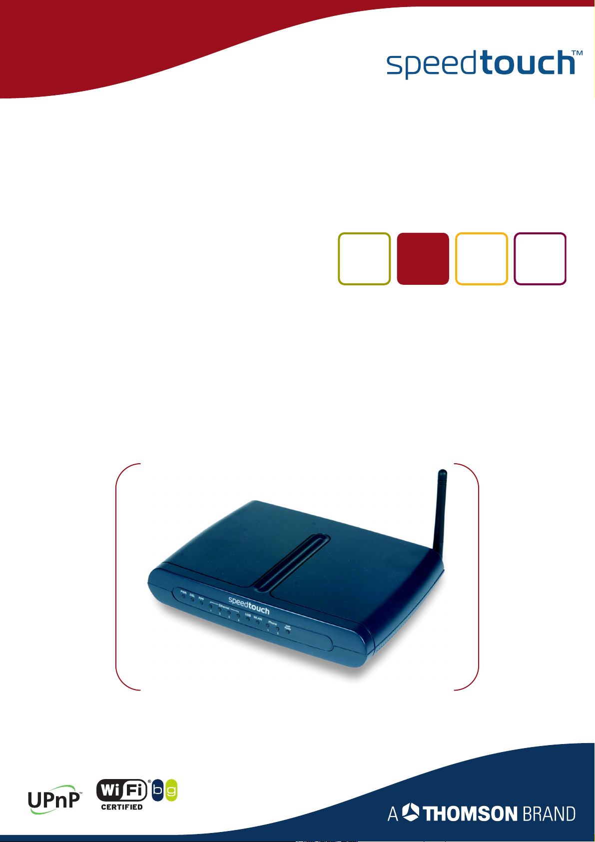
SpeedTouch™716/716g
Broadband Voice IAD
User’s Guide
Release R1.0
SpeedTouch™716g only
Page 2

Page 3

SpeedTouch™
716/716g
User’s Guide
R1.0
Page 4

Copyright
Copyright ©1999-2005 THOMSON. All rights reserved.
Passing on, and copying of this document, use and communication of its contents is not permitted without written authorization
from THOMSON. The content of this document is furnished for informational use only, may be subject to change without notice,
and should not be construed as a commitment by THOMSON. THOMSON assumes no responsibility or liability for any errors or
inaccuracies that may appear in this document.
Thomson Telecom Belgium
Prins Boudewijnlaan, 47
B-2650 Edegem
Belgium
www.speedtouch.com
Trademarks
The following trademarks are used in this document:
SpeedTouch™ is a trademark of THOMSON.
Microsoft®, MS-DOS®, Windows® and Windows NT® are either registered trademarks or trademarks of Microsoft Corpo-
ration in the United States and/or other countries.
UNIX® is a registered trademark of UNIX System Laboratories, Incorporated.
Apple® and Mac OS® are registered trademarks of Apple Computer, Incorporated, registered in the United States and
other countries.
Adobe, the Adobe logo, Acrobat and Acrobat Reader are trademarks or registered trademarks of Adobe Systems, Incorpo-
rated, registered in the United States and/or other countries.
Netscape® and Netscape Navigator® are registered trademarks of Netscape Communications Corporation.
Ethernet™ is a trademark of Xerox Corporation.
UPnP™ is a certification mark of the UPnP™ Implementers Corporation.
Wi-Fi® and the Wi-Fi logo are registered trademarks of the Wi-Fi Alliance. "Wi-Fi CERTIFIED", "Wi-Fi ZONE", "Wi-Fi Alli-
ance", their respective logos and "Wi-Fi Protected Access" are trademarks of the Wi-Fi Alliance.
Other products may be trademarks or registered trademarks of their respective manufacturers.
Document Information
Status: v3.0 (February 2005)
Reference: E-DOC-CTC-20041126-0014
Short Title: User’s Guide ST716/ST716g R1.0
Page 5

Contents
Contents
1 SpeedTouch™ Installation ........................................... 9
1.1 Getting Acquainted with the SpeedTouch™ ................................ 10
1.2 Setting up the SpeedTouch™....................................................... 13
2 SpeedTouch™ Local Networking Setup................... 15
2.1 Ethernet Connection Setup.......................................................... 16
2.2 USB Connection Setup................................................................. 17
2.3 Wireless Connection Setup .......................................................... 19
2.3.1 First-time Wireless Client Association ......................................................................... 21
2.3.2 Connecting Additional Wireless Clients....................................................................... 23
2.4 Securing your Wireless Network.................................................. 24
2.4.1 Encryption ......................................................................................................................25
2.4.2 WEP................................................................................................................................. 26
2.4.3 WPA ................................................................................................................................ 27
2.4.4 WPA-PSK ........................................................................................................................29
2.4.5 802.1x.............................................................................................................................. 31
2.4.6 Restricting Wireless Access .......................................................................................... 33
2.4.7 Hiding your Wireless Network ...................................................................................... 34
2.5 Extending the Range of your Wireless Network .......................... 35
3 Configuration............................................................... 37
E-DOC-CTC-20041126-0014 v3.0
3
Page 6

Contents
4 SpeedTouch™ Internet Connectivity ........................ 39
4.1 Using the MS Windows XP Internet Gateway Device
Control Agent .............................................................................. 40
4.2 Using the SpeedTouch™ Web Pages ............................................ 42
5 SpeedTouch™ Web Interface .................................... 43
5.1 Accessing the SpeedTouch™ Web Pages..................................... 44
5.2 Navigating the SpeedTouch™ Web Pages.................................... 46
5.3 Quick Start ................................................................................... 47
5.4 Status........................................................................................... 52
5.5 Advanced ..................................................................................... 55
5.5.1 Local Network ................................................................................................................ 56
5.5.2 Internet............................................................................................................................ 58
5.5.3 IP Routing ....................................................................................................................... 59
5.5.4 DNS Server..................................................................................................................... 60
5.5.5 Virtual Server ................................................................................................................. 61
5.5.6 Firewall ...........................................................................................................................63
5.5.7 Quality of Service........................................................................................................... 64
5.5.8 IGMP Proxy..................................................................................................................... 65
5.6 Wireless ........................................................................................ 66
5.6.1 Basic................................................................................................................................ 67
5.6.2 Security........................................................................................................................... 68
5.6.3 Access Control ...............................................................................................................69
5.6.4 Repeater.......................................................................................................................... 70
5.7 Voice ............................................................................................ 71
5.8 Diagnostics .................................................................................. 72
5.9 Management ................................................................................ 73
4
E-DOC-CTC-20041126-0014 v3.0
Page 7
Contents
6 Voice over IP................................................................ 77
6.1 Session Initiation Protocol........................................................... 78
6.1.1 Configuration ................................................................................................................. 79
6.1.2 SIP Web Pages ...............................................................................................................81
6.2 Media Gateway Control Protocol ................................................. 83
6.2.1 Configuration ................................................................................................................. 84
6.2.2 MGCP Web Pages.......................................................................................................... 86
6.3 VoIP Call Features........................................................................ 87
6.3.1 Call Transferring ............................................................................................................ 88
6.3.2 Call Waiting ....................................................................................................................89
6.3.3 3-ways Conference Calls ............................................................................................... 90
7 Advanced Configuration............................................. 91
7.1 Setting up a Virtual Server .......................................................... 92
7.2 SNMP ........................................................................................... 94
8 Support ........................................................................97
8.1 Updating your Firmware .............................................................. 98
8.2 UPnP™ on Windows XP Systems................................................. 99
8.3 Reset to Defaults ....................................................................... 102
8.4 Troubleshooting ......................................................................... 103
8.4.1 Diagnostics Tests......................................................................................................... 104
8.4.2 Problems with LAN......................................................................................................105
8.4.3 Upgrading Problems ................................................................................................... 106
E-DOC-CTC-20041126-0014 v3.0
5
Page 8

Contents
6
E-DOC-CTC-20041126-0014 v3.0
Page 9
Used symbols
About this User’s Guide
A note provides additional information about a topic.
A tip provides an alternative method or shortcut to perform an action.
A caution warns you about potential problems or specific precautions that
!
need to be taken.
About this User’s Guide
Terminology
Documentation and
software updates
Generally, the SpeedTouch™716 and SpeedTouch™716g will be referred to as
SpeedTouch™ in this User’s Guide.
THOMSON continuously develops new solutions, but is also committed to improve
its existing products.
For more information on THOMSON's latest technological innovations, documents
and software releases, visit us at:
www.speedtouch.com
E-DOC-CTC-20041126-0014 v3.0
7
Page 10

About this User’s Guide
8
E-DOC-CTC-20041126-0014 v3.0
Page 11
SpeedTouch™ Installation
1 SpeedTouch™ Installation
Introduction Thank you for purchasing the SpeedTouch™ Broadband Voice IAD.
The SpeedTouch™716 and 716g allow ADSL Internet connectivity while providing
voice over IP functions for home and office users.
ADSL functionality Both the SpeedTouch™716 and SpeedTouch™716g support:
ADSL2
RE-ADSL
ADSL2+
and are backward compatible with ADSL.
Wireless functionality If you purchased a SpeedTouch™716g, the SpeedTouch™ also includes a
54 Megabits per second (Mbps) wireless 802.11g interface to offer seamless
connection of wired and wireless worlds from anywhere in the home.
Chapter 1
VoIP functionality The SpeedTouch™ is equipped with two Voice over IP (VoIP) ports allowing high
quality Voice over IP functionality.
Safety instructions Prior to connecting the SpeedTouch™, read the SpeedTouch™ Quick Installation
Guide and Safety Instructions.
E-DOC-CTC-20041126-0014 v3.0
9
Page 12
Chapter 1
SpeedTouch™ Installation
1.1 Getting Acquainted with the SpeedTouch™
Introducing the
SpeedTouch™
Delivery check Next to your SpeedTouch, your DSL package should contain:
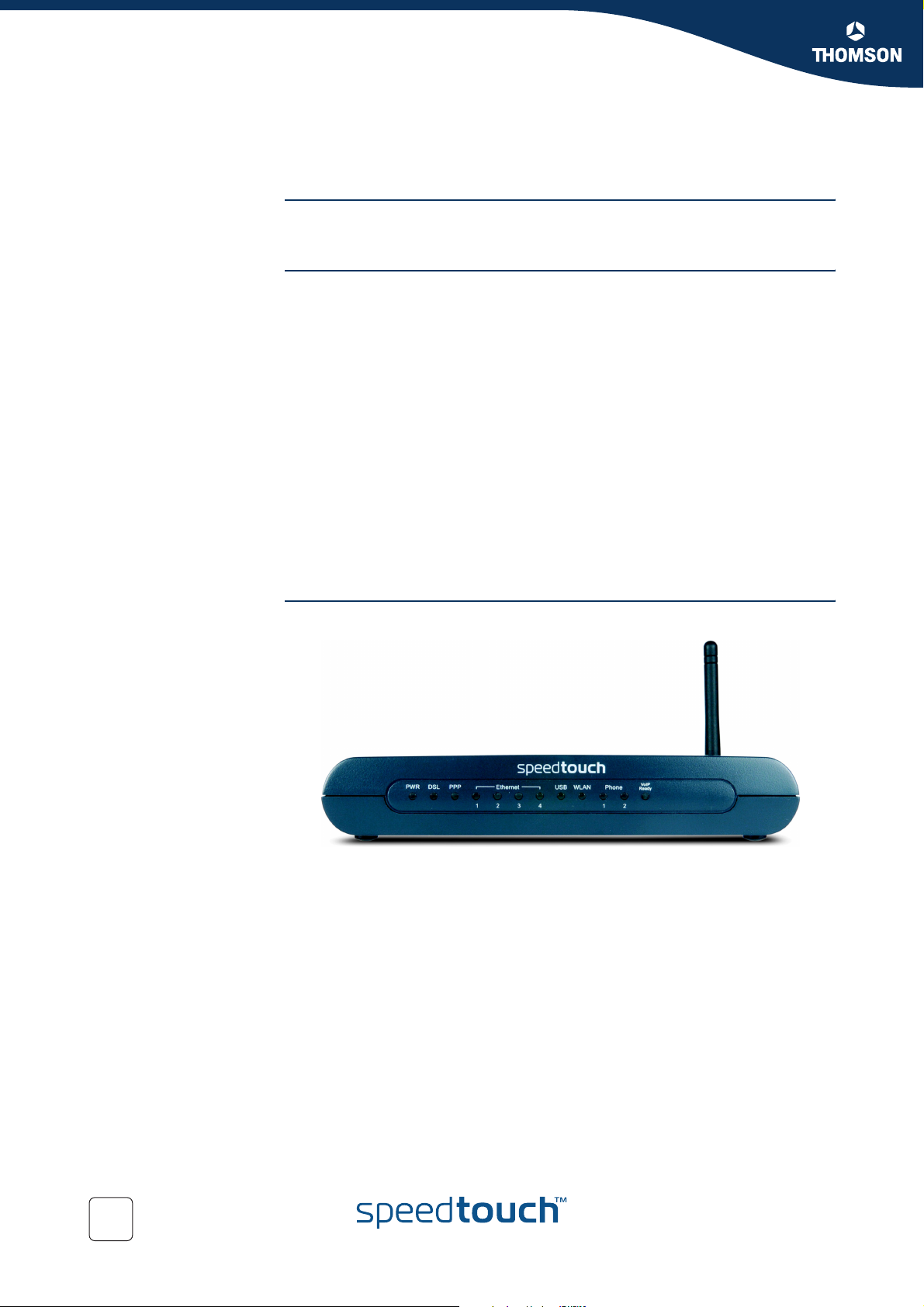
Front panel layout The SpeedTouch™ is presented in a desktop housing:
Make sure to read the safety instructions first.
SpeedTouch™716/716g
Colour coded cables
Yellow Ethernet cable (RJ-45)
Blue USB cable
Grey DSL cable (RJ-11)
Power adapter (18V AC)
SpeedTouch™ Setup CD
Safety Instructions & Regulatory Information booklet
Quick Installation Guide
DSL filter(s) (optional)
SpeedTouch™ wireless networking product(s) (optional)
In case items are missing or damaged, please contact your local distributor.
10
E-DOC-CTC-20041126-0014 v3.0
Page 13
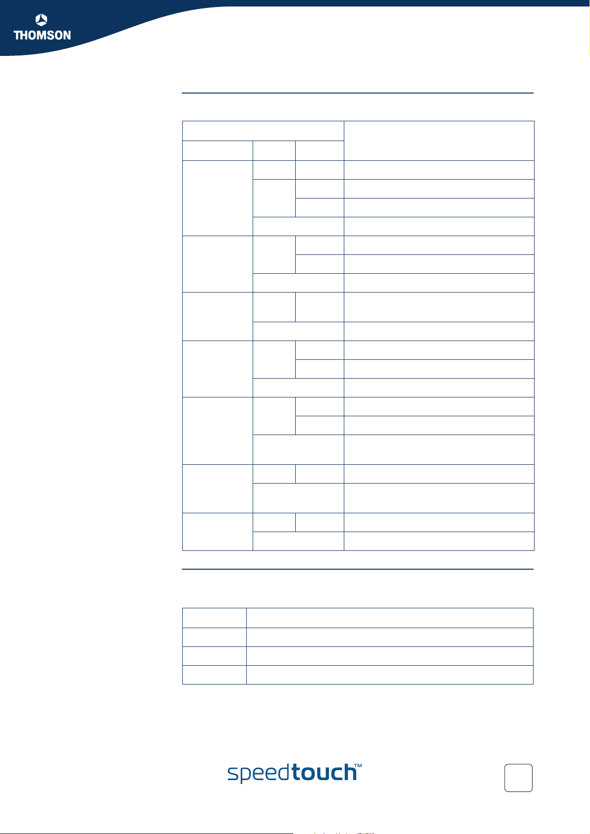
Front panel LEDs
Chapter 1
SpeedTouch™ Installation
Indicator Description
LED Colour Status
PWR Green On Power on.
Red On Startup pending.
Flashing Updating Firmware
Off Power off.
DSL Green Flashing Internet activity.
On DSL synchronised, no Internet activity.
Off Power off or DSL line synchronising.
PPP Green On At least one PPPoA or PPPoE connection is
up. Users can access the Internet now.
SpeedTouch™716g
WLAN LED
Off No PPPoA or PPPoE connection.
Ethernet 1 ~ 4 Green Flashing Ethernet activity.
On Ethernet connection, no activity.
Off No Ethernet connection.
USB Green Flashing USB activity.
On USB connection, no activity.
Off Power off or wait for USB connection
going up.
Phone 1- 2 Green On The phone is off hook.
Off The phone is on hook or no phone
connected.
VOIP Ready Green On VoIP service up.
Off VoIP service down.
If you purchased a SpeedTouch™716g, the SpeedTouch™ is equipped with an
additional LED to indicate the WLAN status:
LED Status Description
E-DOC-CTC-20041126-0014 v3.0
Flashing Wireless activity.
On Wireless LAN connection.
Off No wireless connection.
11
Page 14
Chapter 1
SpeedTouch™ Installation
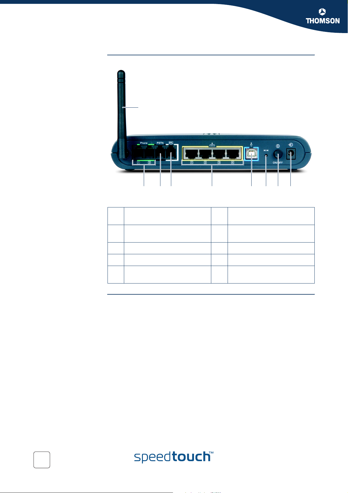
SpeedTouch™ back
panel layout
The following connections are available on your SpeedTouch™:
A
B C D F G H IE
Antenna
A
(SpeedTouch™716g only)
Phone set connector
B
(marked green)
USB port (marked blue)
F
Recessed reset button
G
Aligning the
SpeedTouch™716g
antenna
PSTN port
C
DSL line port (marked grey)
D
10/100Base-T Ethernet switch
E
(marked yellow)
You are able to align the external antenna to optimise the wireless link. The antenna
characteristics are such that wireless links perpendicular to the antenna are
favoured. When the antenna is erect, wireless links in the horizontal plane are
favoured.
Please note that the antenna characteristics are influenced by the environment, for
example by reflections of the radio signal against walls or ceilings. It is advised to
use the received signal strength as indicated by the wireless client manager to
optimise the antenna position for the link to a given client.
Power button (ON/OFF)
H
Power inlet
I
12
E-DOC-CTC-20041126-0014 v3.0
Page 15
1.2 Setting up the SpeedTouch™
ADSL service The appropriate DSL service must be available at your premises:
ADSL service must be enabled on your telephone line.
As both telephone and ADSL service are simultaneously available from the
same copper pair, you will need a central splitter or distributed filters for
decoupling ADSL and telephone signals.
Always contact your Service Provider when installing splitters/filters!
!
Public telephone lines carry voltages that can cause electric shock. Only
install splitter/filters yourself if these are qualified for that purpose.
Chapter 1
SpeedTouch™ Installation
Support of the latest
ADSL standards
ADSL2 ADSL2 (ITU G.992.3 and G.992.4), being the successor of the well-known ADSL
RE-ADSL Reach Extended ADSL (RE-ADSL) (ITU G.992.L) is an extension to ADSL2 that
ADSL2+ ADSL2+ (ITU G.992.5) is an extension to the ADSL2 standard that goes even further
The SpeedTouch™ supports the latest ADSL standards:
ADSL2
RE-ADSL
ADSL2+
and is backward compatible with ADSL.
standard, adds new features and functionality targeted at improving performance
and interoperability, and adds support for new applications, services and
deployment scenarios. Among the changes are:
Improvements in data rate up to 12 Mbps and reach performance.
Rate adaption.
Diagnostics.
Stand-by mode.
allows to significantly extend the reach of throughput capabilities.
in offering optimal broadbanding; it nearly doubles the maximum ADSL
downstream data rates to up to 24 Mbps.
Connect the DSL line The grey DSL port on the SpeedTouch™ is marked .
Use the grey DSL cable provided to wire the SpeedTouch™ DSL port to your
telephone wall outlet or distributed filter.
Connect the power
supply
E-DOC-CTC-20041126-0014 v3.0
Always check first whether the power supply adapter provided is suitable for the
local power specifications. Contact your Service Provider in case of any doubt.
The power inlet on the SpeedTouch™ is marked .
Plug the adapter's coaxial jack into the SpeedTouch™'s power inlet and plug the
power supply into a power socket outlet.
13
Page 16

Chapter 1
SpeedTouch™ Installation
Switch on
SpeedTouch™
Connect your
computer(s)
Once all previous steps are completed, push the ON/OFF button on the back panel
to switch on the SpeedTouch™.
The SpeedTouch™ is ready for service as soon as the Power LED on the front panel
is solid green.
If this LED does not light up, see “8.4 Troubleshooting” on page 103.
To connect your computer(s) with the SpeedTouch™, proceed with
“2 SpeedTouch™ Local Networking Setup” on page 15.
14
E-DOC-CTC-20041126-0014 v3.0
Page 17
SpeedTouch™ Local Networking Setup
2 SpeedTouch™ Local Networking Setup
Introduction The SpeedTouch™ offers you following networking solutions:
Wired Ethernet
See “2.1 Ethernet Connection Setup” on page 16 for more information.
USB (1.1)
You must install the USB drivers, if you want to connect your
!
computer to the SpeedTouch™ over USB. See “2.2 USB Connection
Setup” on page 17 for more information.
Wireless Ethernet
See “2.3 Wireless Connection Setup” on page 19 for more information.
This connection method is only available on the SpeedTouch™716g.
!
Chapter 2
The SpeedTouch™ local
network
By introducing the SpeedTouch™ into your local network, local hosts using one of
the solutions above are able to share a local network, that is:
One computer over USB
Multiple computers over wired Ethernet
In case you purchased a SpeedTouch™716g, multiple wireless clients over
wireless networking
E-DOC-CTC-20041126-0014 v3.0
15
Page 18
Chapter 2
SpeedTouch™ Local Networking Setup
2.1 Ethernet Connection Setup
The SpeedTouch™
Ethernet switch
The SpeedTouch™ four-port 10/100 Mbps auto-sensing MDI/MDI-X Ethernet switch
allows you to create a local Ethernet network of up to four devices, without needing
extra networking devices or to expand an existing 10 or 100Base-T Ethernet
network.
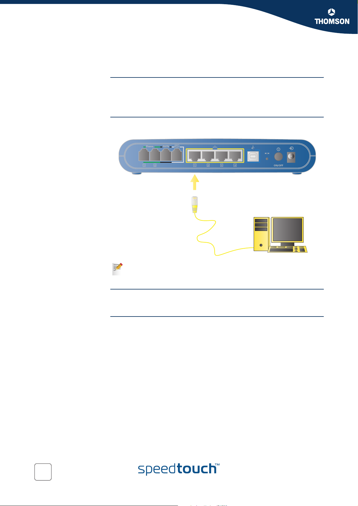
Wiring procedure Use the yellow cable to connect the SpeedTouch™ to your computer or hub (in case
you want to extend your network).
Verifying Ethernet
connectivity
Internet connection
setup
If an external hub or switch is used for wired Ethernet networking, please
follow the installation instructions supplied with the hub for connections
and Ethernet cabling.
If the Ethernet LED of the corresponding port is solid green or flashing, you are
successfully connected to the SpeedTouch™ Ethernet network.
To prepare the SpeedTouch™ for accessing the internet, continue with
“3 Configuration” on page 37.
16
E-DOC-CTC-20041126-0014 v3.0
Page 19
Chapter 2
SpeedTouch™ Local Networking Setup
2.2 USB Connection Setup
Introduction If your computer is not equipped with an Ethernet port, you may want to connect
the computer to the SpeedTouch™ using the USB port on the back panel of the
SpeedTouch™.
Supported Operating
Systems
Procedure Proceed as follows:
USB connectivity is supported for following operating systems:
Microsoft Windows XP
Microsoft Windows 2000
Microsoft Windows Milennium
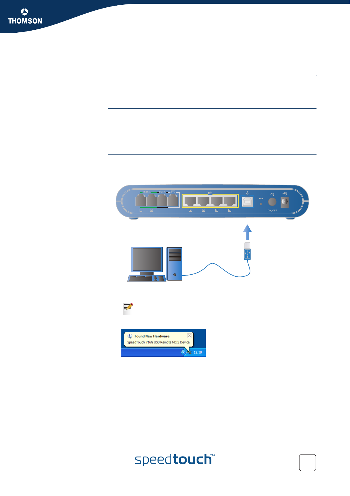
1 Connect the SpeedTouch™ to your computer using the blue USB cable
provided:
E-DOC-CTC-20041126-0014 v3.0
2 Connect the other end of the USB cable to (one of) the USB port(s) on your
computer.
You can also connect your computer to the SpeedTouch™ using a
USB hub.
3 Windows detects the presence of the new Thomson USB Remote NDIS device:
4 If the Found New Hardware Wizard asks your authorisation to connect to
Window Update to search for software select No, not this time and click Next.
17
Page 20
Chapter 2
SpeedTouch™ Local Networking Setup
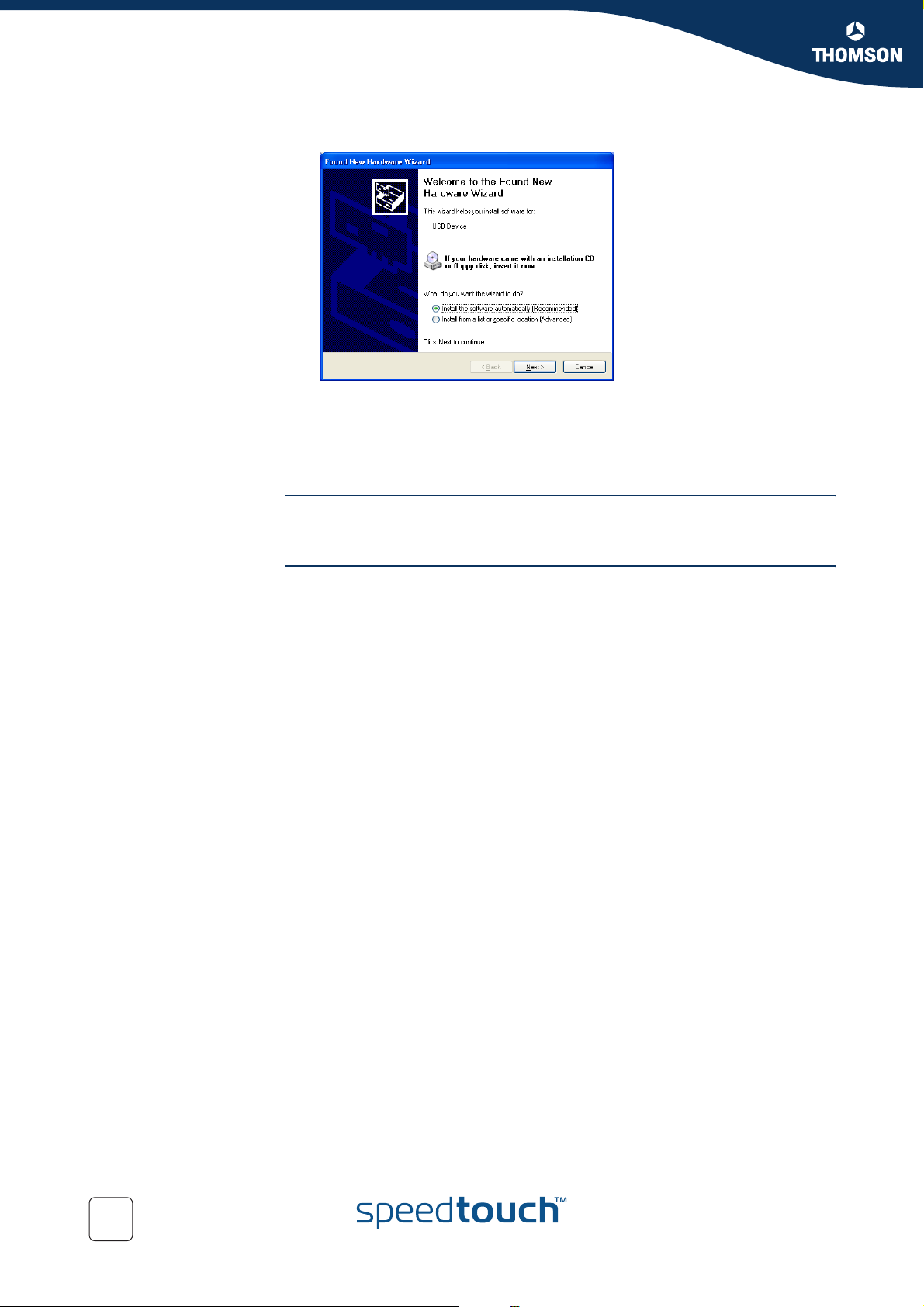
5 Following window appears:
Insert the SpeedTouch™ Setup CD and click Next.
6 The Found New Hardware Wizard installs the necessary divers on your
computer.
7 Click Finish to conclude the installation.
Verifying USB
connectivity
Internet connection
setup
If the USB LED is solid green or flashing, you are successfully connected to the
SpeedTouch™ USB interface.
To prepare the SpeedTouch™ for accessing the internet, continue with
“3 Configuration” on page 37.
18
E-DOC-CTC-20041126-0014 v3.0
Page 21
2.3 Wireless Connection Setup
Chapter 2
SpeedTouch™ Local Networking Setup
SpeedTouch™ wireless
access point
Compatibility Only wireless client adapters at least compliant to IEEE802.11b, will be able to
Radio channels The IEEE802.11g standard for WLANs allows several WLAN networks using
The SpeedTouch™716g features a Wireless LAN Access Point (AP), that behaves as
a networking hub allowing to wirelessly interconnect several devices to the local
(W)LAN and provide - via the SpeedTouch™ DSL router - access to the public
network, for example the Internet.
IEEE802.11g Wireless technology enables these devices to communicate with each
other in a locally mobile fashion, without the need for a wired environment.
communicate with the SpeedTouch™716g and other members of the
SpeedTouch™ (W)LAN environment.
Be aware that only IEEE802.11g compliant wireless clients are able to gain
full profit of the 54 Mbps (Max) bandwidth delivered by the
SpeedTouch™716g.
different radio channels to be co-located. The SpeedTouch™716g supports multiple
radio channels and is able to select the best radio channel at each start-up.
The different channels are overlapping. To avoid interference with another
WLAN make sure that the separation (in terms of frequency, this is channel
number) is as high as possible. It’s recommended to keep at least 3
channels between 2 different WLAN’s. For example, if there is an access
point at channel 5 and an access point at channel 11, then the
SpeedTouch™716g will select channel 1.
The SpeedTouch™716g supports all channels allowed for wireless networking
according to your region’s regulations.
However, depending on local regulations, the number of channels actually allowed
to be used may be additionally restricted. As shown in table below:
E-DOC-CTC-20041126-0014 v3.0
Regulatory Domain Allowed Radio Channels
China 1 to 13
Europe 1 to 13
Israel 5 to 7
Japan 1 to 14
Jordan 10 to 13
Thailand 1 to 14
USA 1 to 11
19
Page 22

Chapter 2
SpeedTouch™ Local Networking Setup
Setting up your wireless
network
Extending your
wireless network
If you are configuring the SpeedTouch™ proceed as follows:
1 Associate your wireless client with the SpeedTouch™.
See “2.3.1 First-time Wireless Client Association” on page 21 for more
information.
2 Configure your SpeedTouch™.
See “3 Configuration” on page 37 for more information.
3 Secure your wireless network.
See “2.4 Securing your Wireless Network” on page 24.
4 Associate the additional wireless clients in your network.
See “2.3.2 Connecting Additional Wireless Clients” on page 23.
The SpeedTouch™716g features Wireless Distribution System (WDS) functionality.
This feature allows you to extend the range of your wireless network by introducing
one or more of WDS-enabled devices into your wireless network.
For more information, see “2.5 Extending the Range of your Wireless Network”.
20
E-DOC-CTC-20041126-0014 v3.0
Page 23
SpeedTouch™ Local Networking Setup
2.3.1 First-time Wireless Client Association
Chapter 2
Preparing the first-time
wireless client
First-time wireless
client configuration
Make sure that:
The SpeedTouch™716g is powered on and ready for service.
The SpeedTouch™716g is in its default configuration.
If needed, reset the SpeedTouch™716g to its default configuration as
described in “8.3 Reset to Defaults” on page 102.
The wireless client is installed on your computer.
The wireless client adapter’s IP configuration is set to dynamically obtain its IP
configuration (DHCP).
Usually this is the default TCP/IP configuration for (wireless) Ethernet
interfaces of your computer.
The wireless client is correctly configured for associating to the
SpeedTouch™716g wireless access point (See below).
To be able to connect to the SpeedTouch™ wireless network, your wireless client
must be correctly configured for the default network name. As the
SpeedTouch™716g broadcasts its network name to the wireless clients, you can
select the SpeedTouch™716g wireless network (for example SpeedTouch012345)
from a list of available networks. Depending on your wireless client a wireless icon
may become green or a message similar to the following may pop up:
“Successfully joined Wireless network SpeedTouch012345”.
Some wireless clients do not automatically join a wireless network. In this
case, follow the instructions for the wireless client software to initiate
association.
E-DOC-CTC-20041126-0014 v3.0
21
Page 24
Chapter 2
SpeedTouch™ Local Networking Setup
First-time association
example
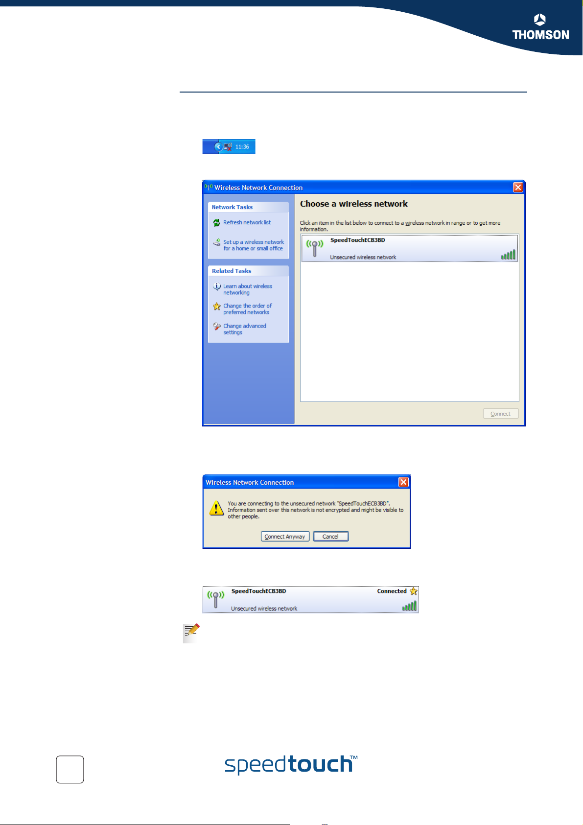
To associate your wireless client to the SpeedTouch™716g on a computer running
MS Windows XP Service Pack 2:
1 Click the network icon in the notification area.
2 The Wireless Network Connection window appears:
In the Choose a wireless network list, select the SpeedTouch™716g wireless
network and click Connect.
3 Following window appears:
Click Connect Anyway.
4 Your computer is now connected to the SpeedTouch™716g wireless network:
Other Operating Systems usually use a dedicated client manager to
configure you wireless settings. For more information, see your wireless
client’s user documentation.
22
E-DOC-CTC-20041126-0014 v3.0
Page 25
SpeedTouch™ Local Networking Setup
2.3.2 Connecting Additional Wireless Clients
Preconditions Make sure that:
The SpeedTouch™ is powered on and ready for service.
Optionally, the SpeedTouch™ wireless settings have been personalised.
The wireless client adapters are installed on all computers you want to
connect to the WLAN.
Chapter 2
Wireless client
configuration
SpeedTouch™716g
configuration
Configure your wireless client with the same network name (SSID) and encryption
as the SpeedTouch™716g.
For more information, consult your wireless client’s user documentation.
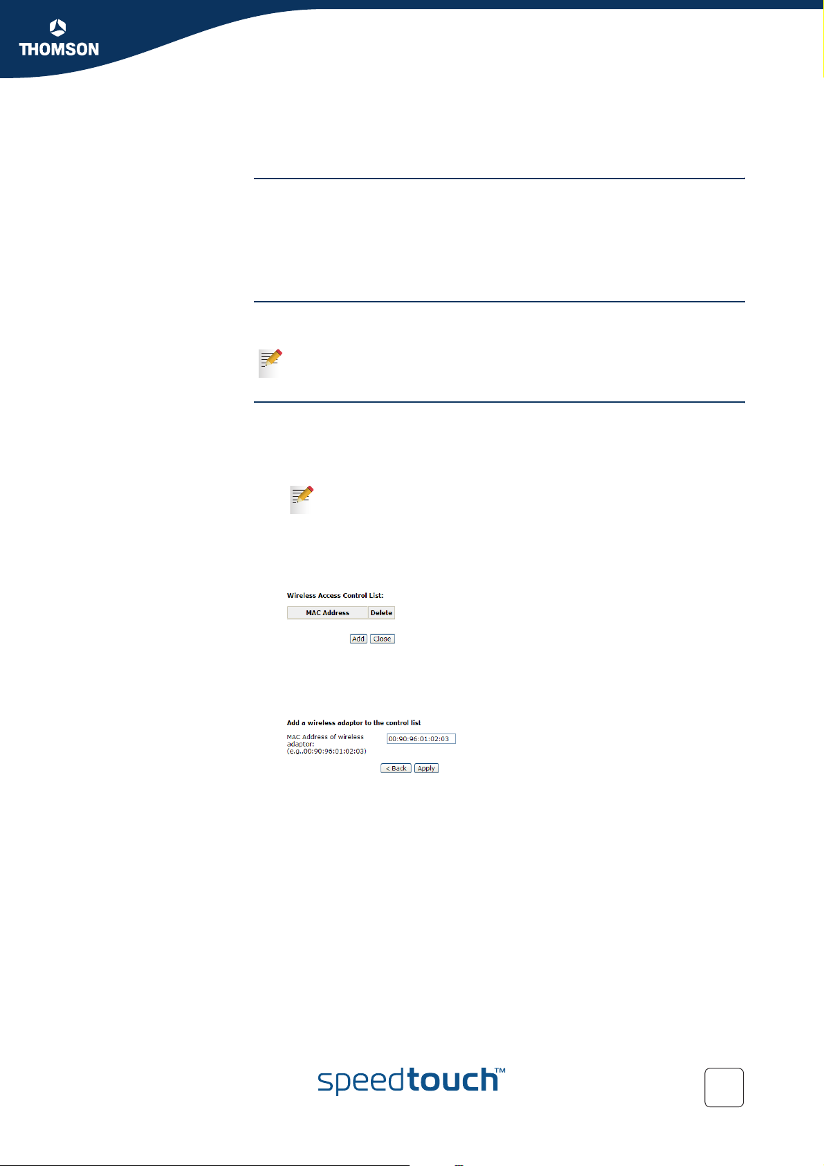
If the SpeedTouch™ Access Control List (ACL) is On in Deny mode some additional
configuration is needed:
1 Open the SpeedTouch™ web pages on a computer that is listed in the ACL or
that is connected using wired Ethernet/USB.
For more information, see “5.1 Accessing the SpeedTouch™ Web
Pages” on page 44.
2 Browse to Wireless > Access Control.
3 The Access Control page appears. Click View Access Control List.
4 The Wireless Action Control List page appears:
Click Add.
5 Type the MAC Address of your wireless device in the MAC address of wireless
adaptor field:
E-DOC-CTC-20041126-0014 v3.0
Click Apply.
23
Page 26

Chapter 2
SpeedTouch™ Local Networking Setup
2.4 Securing your Wireless Network
Introduction After going through the SpeedTouch™716g configuration setup procedures, it is
strongly recommended to secure your wireless network.
If you choose not to secure your wireless network, be aware that all clients
!
within the range of your wireless network are able to connect to the
SpeedTouch™ network an to use your Internet connection.
SpeedTouch™ wireless
security options
The SpeedTouch™716g allows you to:
Encrypt the data sent over your wireless network.
See “2.4.1 Encryption” for more information.
Restrict the access to the SpeedTouch™716g wireless network.
See “2.4.6 Restricting Wireless Access”for more information.
Hide your Network Name (SSID) from other users.
See “2.4.7 Hiding your Wireless Network” for more information.
24
E-DOC-CTC-20041126-0014 v3.0
Page 27
SpeedTouch™ Local Networking Setup
2.4.1 Encryption
Methods The SpeedTouch™ offers you following encryption methods:
Disabled
WEP
WPA
WPA-PSK
802.1x
Before configuring the SpeedTouch™ encryption, make sure you know
which encryption methods are supported by your wireless client.
Chapter 2
E-DOC-CTC-20041126-0014 v3.0
25
Page 28
Chapter 2
SpeedTouch™ Local Networking Setup
2.4.2 WEP
Definition The Wired Equivalent Protocol (WEP) relies on a secret key that is shared between
the wireless client (for example a laptop with a wireless client) and the
SpeedTouch™716g. The fixed secret key is used to encrypt data before being
transmitted.
Configuring WEP on the
SpeedTouch™
Proceed as follows:
1 Open the SpeedTouch™ web pages.
For more information, see “5.1 Accessing the SpeedTouch™ Web
Pages” on page 44.
2 Browse to Wireless > Security.
3 In the Wi-Fi Protected Access list, click 64-bit WEP or 128-bit WEP.
4 Following fields appear:
Authentication Type:
The SpeedTouch™716g supports two authentication types:
Open System:
All wireless clients are able to authenticate. The WEP key is only
used to encrypt/decrypt data.
Shared Key:
Only wireless clients using a correct SSID and WEP key are able to
authenticate. The WEP key is used to authenticate and to encrypt/
decrypt data.
Format:
This section allows you to choose between:
Hexadecimal digits.
ASCII characters.
Key 1 to 4
Default Transmission Key
5 Enter your settings.
6 Click Apply.
Wireless client(s)
configuration
26
Configure your wireless client(s) with the new WEP settings.
For more information, see your wireless client’s user documentation.
E-DOC-CTC-20041126-0014 v3.0
Page 29
SpeedTouch™ Local Networking Setup
2.4.3 WPA
Definition WPA Enterprise is a part of the Wi-Fi Protected Access standard. In this mode,
authentication is done by a dedicated authentication server, which is normally not
available for residential use.
RADIUS Server Remote Authentication Dial-in User Service (RADIUS) is a protocol for carrying
authentication, authorization, and configuration information between a Network
Access Server which desires to authenticate its links and a shared Authentication
Server.
Chapter 2
Configuring WPA on the
SpeedTouch™
Proceed as follows:
1 Open the SpeedTouch™ web pages.
For more information, see “5.1 Accessing the SpeedTouch™ Web
Pages” on page 44.
2 Browse to Wireless > Security.
3 In the Wi-Fi Protected Access list, click WPA.
4 Following fields appear:
WPA Group Rekey Interval:
The time for the WPA group rekey interval in seconds.
RADIUS Server IP Address:
The IP Address of the RADIUS Server.
RADIUS UDP Port:
Port 1812 is the reserved RADIUS-authentication port described in
RFC2138. Earlier RADIUS clients use port 1945.
RADIUS Shared Secret:
A share secret is like a password, which is used between Internet
Authentication Service (IAS) and the specific RADIUS client to verify
identity. Both IAS and the RADIUS client must be use the same shared
secret for successful communication to occur. Enter the words for the
share secret.
Data Encryption (WPA):
Select the data encryption for the WPA mode. Following encryption
types are available:
TKIP:
The Temporal Key Integration Protocol (TKIP) takes the original
master key only as a starting point and derives its encryption keys
mathematically from this master key. Then it regularly changes and
rotates the encryption keys so that the same encryption key will be
never used twice.
AES:
The Advanced Encryption Standard (AES) provides security
between client workstations operating in ad hoc mode. It uses a
mathematical ciphering algorithm that employs variable key sizes
of 128, 192 or 256 bits.
TKIP+AES:
Combines the features and functions of TKIP and AES.
5 Enter your settings.
6 Click Apply.
E-DOC-CTC-20041126-0014 v3.0
27
Page 30

Chapter 2
SpeedTouch™ Local Networking Setup
Wireless client
configuration
Configure your wireless clients with the same settings.
For more information, see your wireless client’s user documentation.
28
E-DOC-CTC-20041126-0014 v3.0
Page 31

SpeedTouch™ Local Networking Setup
2.4.4 WPA-PSK
Definition Contrary to WPA, WPA-Pre Shared Key (WPA-PSK) does not need the presence of
an authentication server on your network.
WPA Personal features 3 basic improvements over WEP.
1 Mutual authentication of access point and client via a 4-way handshake. In this
handshake, both client and access point check whether they share the same
Pre-Shared Key (without sending the PSK “in the clear”).
2 Stronger encryption, using the Temporal Key Integrity Protocol (TKIP). In stead
of using a fixed WEP key, TKIP uses in pairs temporary session keys which are
derived from the PSK during the 4-way handshake.
3 Message Integrity Check (MIC), a strong mathematical function in which the
recipient and transmitter each compute and compare the MIC. Non-matching
MICs reveal that a third party has been tampering the data to try and hack the
system.
Chapter 2
Configuring WPA-PSK
on the SpeedTouch™
Proceed as follows:
1 Open the SpeedTouch™ web pages.
For more information, see “5.1 Accessing the SpeedTouch™ Web
Pages” on page 44.
2 Browse to Wireless > Security.
3 In the Wi-Fi Protected Access list, click WPA-PSK.
4 Following fields appear:
Format:
Choose the typing method of encryption key. You have to click either
Hexadecimal digits or ASCII characters and type the keys on the field of
Pre-Share Key.
Pre-Share Key:
Please type the key to be between 8 and 63 characters, or 64 hexadecimal
digits. Only the devices with a matching key that you set here can join
this network.
WPA Group Rekey Interval:
Enter the time for the WPA group rekey interval. The unit is second.
Data Encryption (WPA):
Select the data encryption for the WPA mode. Following encryption
types are available:
TKIP:
Takes the original master key only as a starting point and derives its
encryption keys mathematically from this master key. Then it
regularly changes and rotates the encryption keys so that the same
encryption key will be never used twice.
AES:
Provides security between client workstations operating in ad hoc
mode. It uses a mathematical ciphering algorithm that employs
variable key sizes of 128, 192 or 256 bits.
TKIP+AES:
Combines the features and functions of TKIP and AES.
5 Enter the configuration of your choice.
6 Click Apply.
E-DOC-CTC-20041126-0014 v3.0
29
Page 32

Chapter 2
SpeedTouch™ Local Networking Setup
Wireless client(s)
configuration
Configure your wireless client(s) with the same settings.
For more information, see your wireless client’s user documentation.
30
E-DOC-CTC-20041126-0014 v3.0
Page 33
SpeedTouch™ Local Networking Setup
2.4.5 802.1x
Definition When a wireless client requests access to a network, it is required to be
authenticated by a central authentication server (RADIUS Server). Only an
authenticated user can access the wireless network.
RADIUS Server Remote Authentication Dial-in User Service (RADIUS) is a protocol for carrying
authentication, authorization, and configuration information between a Network
Access Server which desires to authenticate its links and a shared Authentication
Server.
Components Following components are needed to establish an 802.1x environment in your
network.:
Windows 2000 Server: RADIUS server is installed using “Internet
Authentication Service” and Certificate Services is installed
AP (Router): It should be connected to Windows 2000 Advanced Server
through the LAN port. The DHCP server for the router is used and 802.1x must
be enabled.
802.1x client: A WLAN card supporting WEP.
Chapter 2
Configuring 802.1x on
the SpeedTouch™
Proceed as follows:
1 Open the SpeedTouch™ web pages.
For more information, see “5.1 Accessing the SpeedTouch™ Web
Pages” on page 44.
2 Browse to Wireless > Security.
3 In the Wi-Fi Protected Access list, click 802.1x.
4 Following fields appear:
RADIUS Server IP Address:
The IP Address of the RADIUS Server.
RADIUS UDP Port:
Except for the IP address of the RADIUS Server, you have to enter the
port number for the server. Port 1812 is the reserved RADIUSauthentication port described in RFC2138. Earlier AP (RADIUS clients)
use port 1945. The default value will be shown on this box. You can keep
and use it.
RADIUS Shared Secret:
A share secret is like a password, which is used between RADIUS Server
and the specific AP (RADIUS client) to verify identity. Both RADIUS
Server and the AP (RADIUS client) must be use the same shared secret
for successful communication to occur. Enter the words for the share
secret.
5 Enter your settings.
6 Click Apply.
E-DOC-CTC-20041126-0014 v3.0
31
Page 34

Chapter 2
SpeedTouch™ Local Networking Setup
Wireless client(s)
configuration
Configure your wireless client(s) with the new authentication and encryption
settings.
For more information, see your wireless client’s user documentation.
32
E-DOC-CTC-20041126-0014 v3.0
Page 35
2.4.6 Restricting Wireless Access
ACL The Access Control List (ACL) enables you to allow/deny access to your wireless
network for specific wireless clients.
ACL modes Following modes are supported:
Off:
All new stations are allowed to access the SpeedTouch™716g WLAN.
On in Allow mode
Only stations that are listed in the ACL are allowed to access the
SpeedTouch™716g WLAN.
On in Deny mode
All stations that are not listed in the ACL are allowed to access the
SpeedTouch™716g WLAN.
Chapter 2
SpeedTouch™ Local Networking Setup
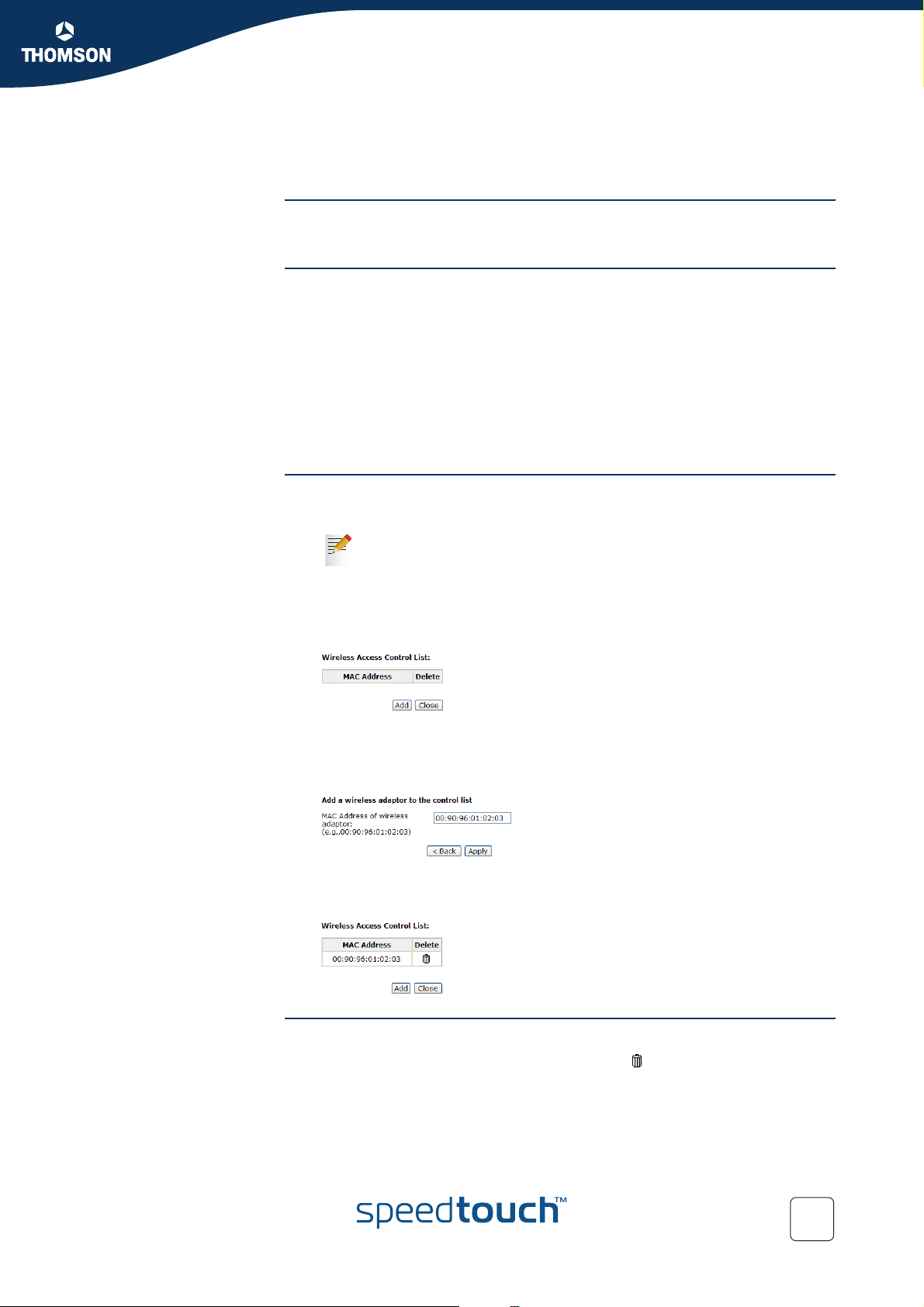
Adding a new ACL entry To add a new MAC address to your wireless MAC address filters:
1 Open the SpeedTouch™ web pages.
For more information, see “5.1 Accessing the SpeedTouch™ Web
Pages” on page 44.
2 Browse to Wireless > Access Control.
3 Click View Access Control List.
4 The Wireless Access Control List page appears:
Click Add.
5 Enter the MAC Address of the wireless device you want to allow in the MAC
address of wireless adaptor field:
Click Apply.
6 The SpeedTouch™716g adds the entry to the Access Control List:
Removing an ACL entry To delete the a MAC address from the list:
1 On the Wireless Action Control List page, click .
2 The SpeedTouch™716g prompts you to confirm your choice. Click Ye s.
3 The entry has been deleted.
E-DOC-CTC-20041126-0014 v3.0
33
Page 36
Chapter 2
SpeedTouch™ Local Networking Setup
2.4.7 Hiding your Wireless Network
SSID The WLAN's 'radio' link is a shared medium. As no physical connection exists
SSID broadcast By default the SpeedTouch™716g broadcasts it’s SSID, allowing you to easily
between the SpeedTouch™716g and its wireless clients, a name must be given to
allow unique identification of your WLAN radio link. This is done by the
Service Set ID (SSID), also referred to as Network Name. Wireless clients must be
part of this SSID environment in order to be able to communicate with other clients
on the (W)LAN - including the SpeedTouch™716g.
recognise your wireless network in the list of available wireless networks. Once you
have configured your wireless clients, it is recommended to disable this feature.
Disabling SSID
broadcast
Proceed as follows:
1 Open the SpeedTouch™ web pages and browse to Wireless > Basic Settings:
For more information, see “5.1 Accessing the SpeedTouch™ Web
Pages” on page 44.
2 Select Hide Wireless Network (Hidden SSID).
3 Click Apply.
Disabling the SSID broadcast does not mean that your wireless network is
!
100% secure: hackers can still find your SSID by monitoring your network
traffic. Therefore make sure to use it in combination with data encryption.
34
E-DOC-CTC-20041126-0014 v3.0
Page 37
SpeedTouch™ Local Networking Setup
2.5 Extending the Range of your Wireless Network
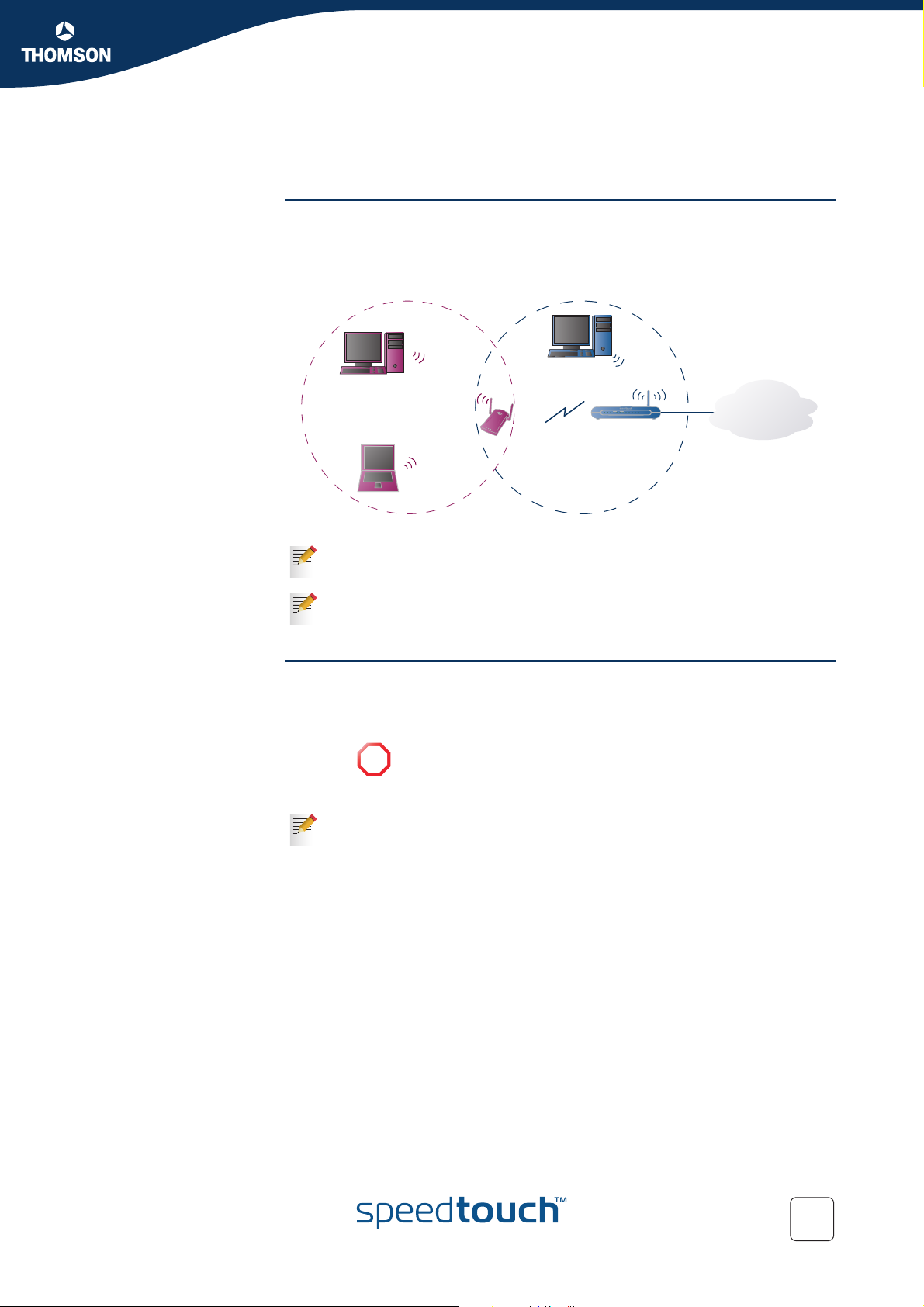
Introduction The Wireless Distribution System (WDS) allows you to extend the range of your
SpeedTouch™716g by means of one or more wireless repeaters (e.g. a
SpeedTouch™180). The following illustration depicts two WDS-enabled devices
communicating via WDS:
Chapter 2
WDS Link
SpeedTouch™180
DSL PPP WLANEthernet
SpeedTouch™716
The SpeedTouch™716g allows you to configure up to four WDS links.
Repeaters extend the coverage area of your wireless LAN, however bear in
mind that throughput is reduced for wireless clients that are connected
through the repeater.
Preconditions Your wireless repeater must be WDS-enabled.
Both SpeedTouch™716g and your wireless repeater must use:
The same WEP key if WEP is enabled.
WPA encryption is not supported when using WDS.
!
The same fixed channel.
The SpeedTouch™716g and your wireless repeater do not necessarily need
to use the same SSID. Using different SSIDs allows you to force your
wireless clients to use either the access point of the SpeedTouch™716g or
the access point of your wireless repeater.
VoIPReady
PhoneUSBPWR
1432
Internet
E-DOC-CTC-20041126-0014 v3.0
35
Page 38
Chapter 2
SpeedTouch™ Local Networking Setup
SpeedTouch™716g
configuration
Wireless repeater
configuration
Proceed as follows:
1 Open the SpeedTouch™ web pages.
For more information, see “5.1 Accessing the SpeedTouch™ Web
Pages” on page 44.
2 On the top menu, click Wireless.
3 On the menu on the left, click Repeater.
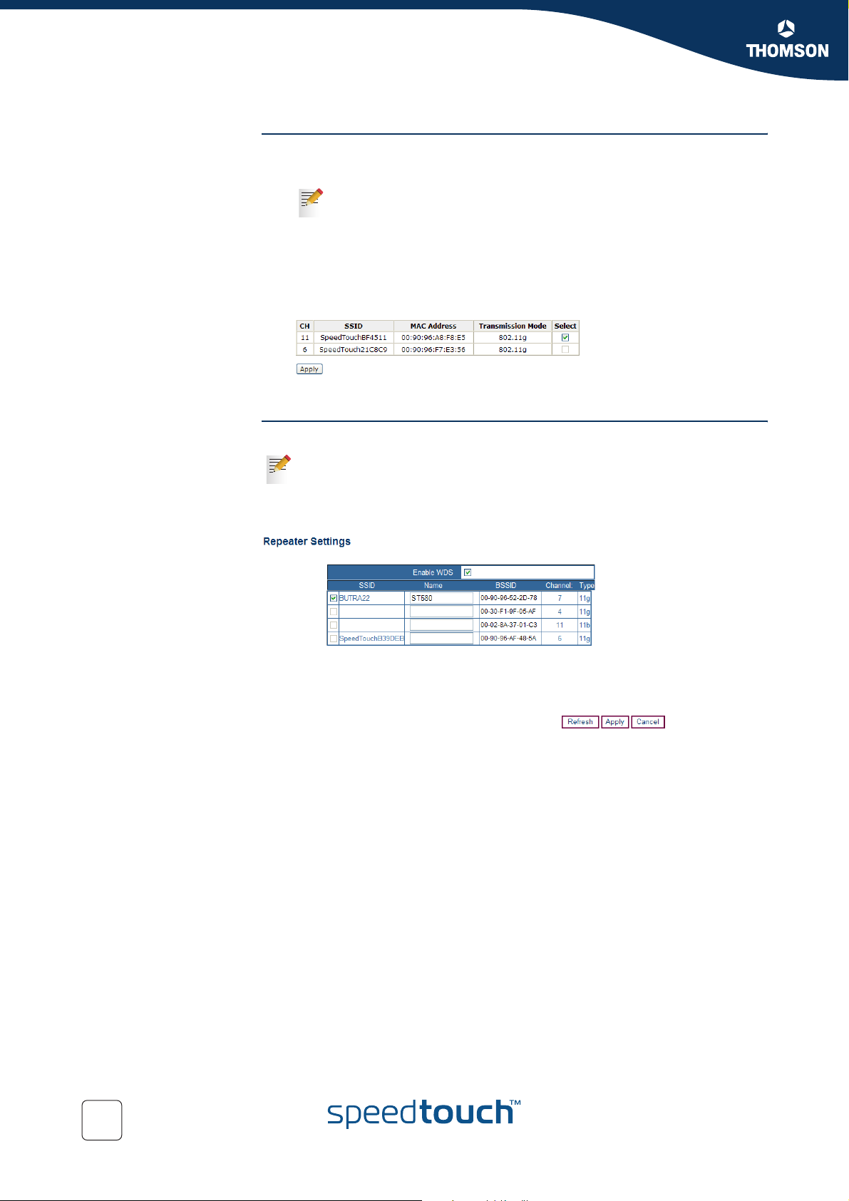
4 Click Scan Now to scan all radio channels for wireless networks.
5 The SpeedTouch™716g lists the available networks in following table:
6 Select your wireless repeater from the list and click Apply.
Configure the WDS link with the SpeedTouch™ on your wireless repeater.
For more information, consult your wireless repeater’s user documentation.
As an example, the picture below shows the repeater settings of a
SpeedTouch™180:
36
E-DOC-CTC-20041126-0014 v3.0
Page 39
3Configuration
Internet connectivity Some configuration may be required to prepare the SpeedTouch™ for Internet
connectivity.
Chapter 3
Configuration
What you need from
your ISP
Prerequisites Make sure that:
In most cases, you need a user account with an Internet Service Provider (ISP) for
Internet access.
For this account, your ISP will provide you with:
A user name (logon ID).
A password.
Other information may be required depending on the ISP’s specific requirements
and service profile selection.
The SpeedTouch™ device is correctly set up and turned on as described in
“1.2 Setting up the SpeedTouch™” on page 13.
The SpeedTouch™ device is in its default configuration state. See “8.3 Reset
to Defaults” on page 102 for resetting your SpeedTouch™.
The computer’s Operating System supports TCP/IP and its Ethernet interface is
configured for obtaining its IP configuration dynamically.
In case of problems you can also configure the computer’s Ethernet or
!
USB interface with a static private IP address, for example 192.168.1.2,
192.168.1.3, but make sure NOT to use 192.168.1.254 as this is the
default IP address of the SpeedTouch™.
Your web browser is capable and allows to run Javascripts.
For more information, see your web browser’s help.
Configuration
procedure
E-DOC-CTC-20041126-0014 v3.0
Proceed as follows:
1 Start the web browser on your computer.
2 Browse to the SpeedTouch™ web pages at http://192.168.1.254.
3 The SpeedTouch™ prompts you to enter user name and password. Type
“admin” in both fields and click OK.
4 Your browser connects to the SpeedTouch™ web pages.
5 On the top menu, click Quick Start.
6 On the left menu, click Quick Setup.
7 The Quick Setup wizard will guide you through the configuration of your
SpeedTouch™. Follow the instructions and enter the required information
where needed. This information should be provided by your ISP.
For more information on the different windows shown during this
configuration, see “ The Quick Setup page” on page 47.
8 At the end of the configuration your SpeedTouch™ will reboot in order to
apply the new configuration.
37
Page 40

Chapter 3
Configuration
38
E-DOC-CTC-20041126-0014 v3.0
Page 41
SpeedTouch™ Internet Connectivity
4 SpeedTouch™ Internet Connectivity
Introduction This chapter provides information on how to configure your SpeedTouch™
according to your preferences and how to access the Internet.
Access methods As soon as the SpeedTouch™ and your computers have been configured as
outlined in “3 Configuration” on page 37, you are able to connect to the WAN or
Internet.
Depending on the configuration of the SpeedTouch™ you may have:
Direct access
As soon as the initial configuration has been done, continuous and immediate
access is available via the DSL line.
Dial-in access
Access must be explicitly established, e.g. by “dialing” into a Broadband
Remote Access Server (BRAS).
The applied connection protocol model depends on the service profile you selected
to configure the SpeedTouch™ and should correspond with the Service Provider’s
requirements.
Chapter 4
Direct access As mentioned, as soon as the initial configuration has been done, immediate and
uninterrupted WAN access is provided.
In case of direct access, the remote organization might ask for a user name
and password on an Internet welcome page.
Dial-in access The SpeedTouch™ supports both most popular connection methods: PPP over ATM
(PPPoA) and PPP over Ethernet (PPPoE).
The connection method depends on the service profile you selected to configure
the SpeedTouch™ and should correspond with the service Provider’s requirements.
Routed PPPoA: the SpeedTouch™ needs to be configured for the Routed
PPPoA Service.
Routed PPPoE: the SpeedTouch™ needs to be configured for the Routed
PPPoE Service.
Both Services are available via the SpeedTouch™ Quick Setup.
Using the
SpeedTouch™
PPP dial-in client
SpeedTouch™’s embedded PPP dial-in client allows you to establish an Internet
connection for all (or a selection of) computers residing on your local network,
using only one computer of the network to control the client.
If this computer runs:
MS Windows XP
you can use MS Windows XP’s Internet Gateway Device Control Client.
See “4.1 Using the MS Windows XP Internet Gateway Device Control Agent”
on page 40 to proceed.
Another Operating System
you can use the SpeedTouch™ web pages.
See “4.2 Using the SpeedTouch™ Web Pages” on page 42 to proceed.
E-DOC-CTC-20041126-0014 v3.0
39
Page 42
Chapter 4
SpeedTouch™ Internet Connectivity
4.1 Using the MS Windows XP Internet Gateway
Introduction MS Windows XP users can easily establish PPP sessions, without the need of first
Preconditions Following conditions must be met:
Device Control Agent
browsing to the SpeedTouch™ web pages, thanks to Windows XP Internet Gateway
Device Discovery and Control Client that allows you to control the SpeedTouch™
directly from your PC.
UPnP™ (subcomponent of Windows XP’s Networking Services) must be
added to your Windows XP system (see “8.2 UPnP™ on Windows XP
Systems” on page 99).
Internet Gateway Device Discovery and Control Client (subcomponent of
Windows XP’s Networking Services) must be enabled on your Windows XP
system (see “8.2 UPnP™ on Windows XP Systems” on page 99).
If your computer runs Windows XP Service Pack 2 (SP2) and you are using the
Windows Firewall, make sure the Windows Firewall allows incoming network
connections for the UPnP service (see “ Windows firewall configuration” on
page 100).
Make sure UPnP™ is enabled on the SpeedTouch™ (see “The UPnP page” on
page 57).
Starting an Internet
session
Proceed as follows:
1 Click (Settings >) Control Panel on the Start menu.
2 The Control Panel window appears. Go to (Network and Internet Connections
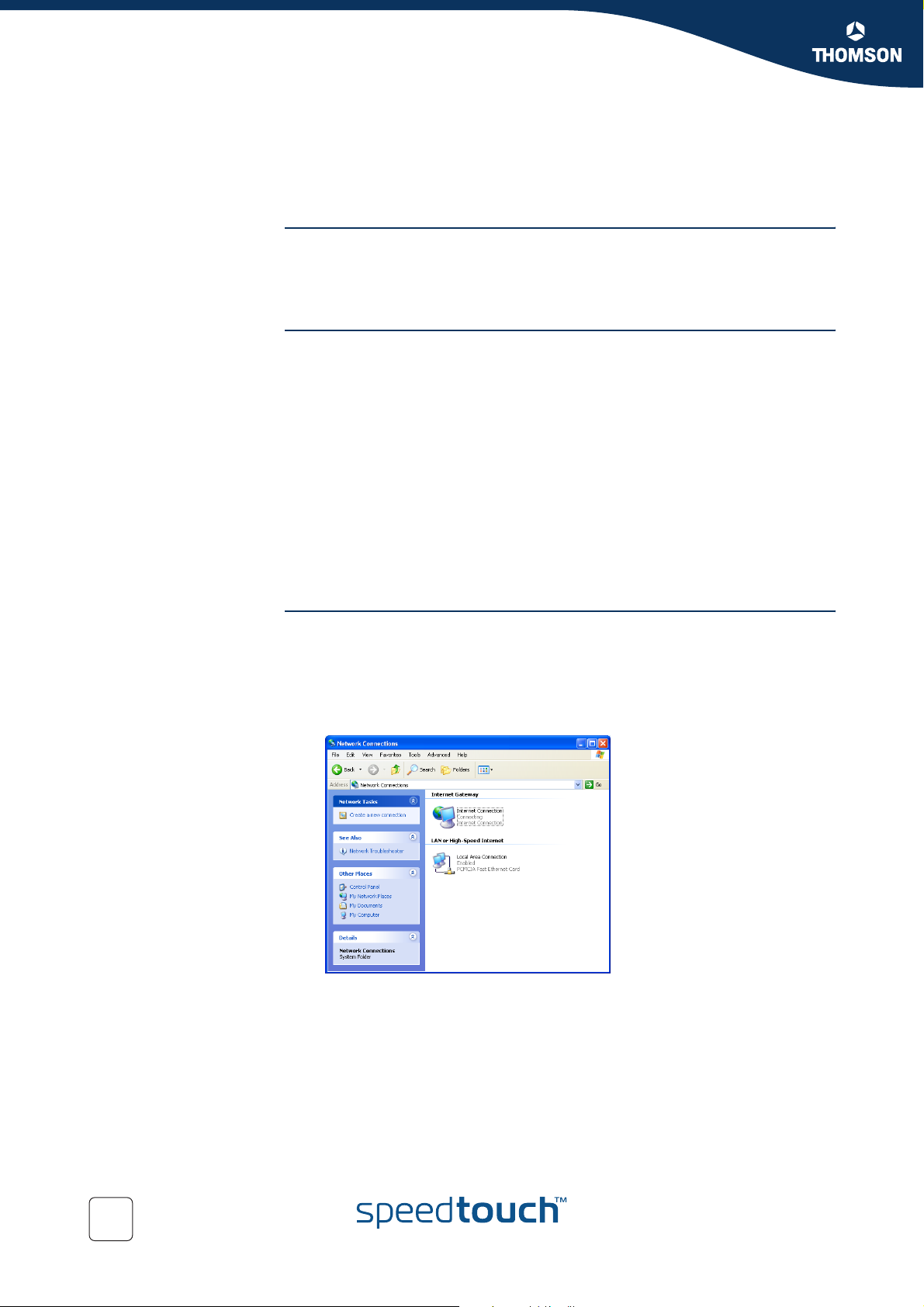
>) Network Connections.
3 The Network Connections window appears:
Next to your Network connection(s), you can find an Internet Gateway icon,
representing the SpeedTouch™ Internet Gateway Device Internet connection
ability.
4 Double-click the Internet Connection icon.
As a result SpeedTouch™’s embedded PPP dial-in client establishes the Internet
connection. The Internet Gateway icon displays connected and your PC is online.
You can open a web browser and surf the Internet.
40
E-DOC-CTC-20041126-0014 v3.0
Page 43
Chapter 4
SpeedTouch™ Internet Connectivity
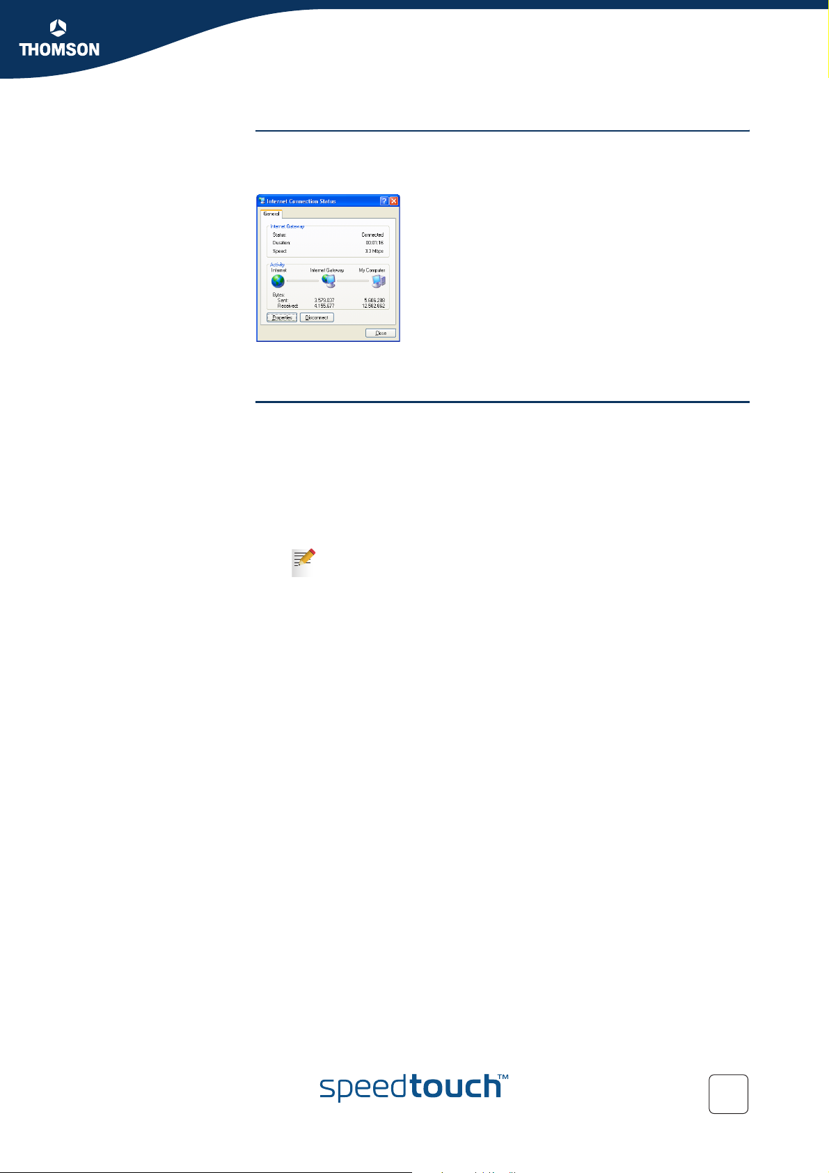
The connected Internet
Gateway
Terminating an Internet
session
As long as the SpeedTouch™’s embedded PPP dial-in client is connected, you are
able to view the connection status and some counters by double-clicking the
Internet
More detailed monitoring is provided via the SpeedTouch™ Status pages. See
“5.4 Status” on page 52.
Proceed as follows:
Connection icon in your PC’s Network Connections window:
1 Click (Settings >) Control Panel on the Start menu.
2 The Control Panel window appears.
Go to (Network and Internet Connections >) Network Connections.
3 The Network Connections window appears.
4 Right-click the Internet Connection icon and select Disconnect to close the
session.
You can also double-click the icon. As a result the Internet Connection
Status window appears from which a Disconnect button is available
to close the session.
As a result SpeedTouch™’s embedded PPP dial-in client will close the Internet
connection. The Internet Gateway icon displays disconnected and your computers
are offline.
E-DOC-CTC-20041126-0014 v3.0
41
Page 44
Chapter 4
SpeedTouch™ Internet Connectivity
4.2 Using the SpeedTouch™ Web Pages
Introduction As the SpeedTouch™ web pages are controllable from any Operating System with
an installed web browser, the method to establish PPP sessions described below
can be used by any computer system.
Starting an Internet
session
Proceed as follows:
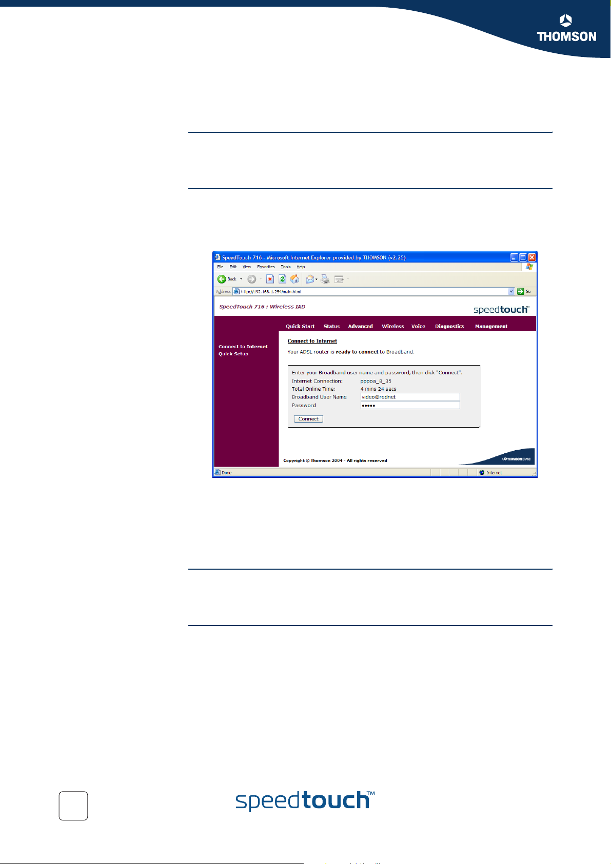
1 Open a web browser on your computer and browse to the SpeedTouch™ web
pages (see “5.1 Accessing the SpeedTouch™ Web Pages” on page 44 for
more information):
2 Enter your user name and password in the appropriate fields.
3 Click Connect.
As a result SpeedTouch™’s embedded PPP dial-in client establishes the Internet
connection.
You can open another web browser or continue with this one and surf the Internet.
During the Internet
session
Terminating an Internet
session
42
You are able to overview and monitor your Internet connectivity as long as the
session is running via the SpeedTouch™ Status pages. See “5.4 Status” on
page 52.
To close an active Routed PPP connection:
1 Open a web browser on your computer and browse to the SpeedTouch™ web
pages (see “5.1 Accessing the SpeedTouch™ Web Pages” on page 44 for
more information).
2 You web browser opens the Connect to Internet page.
3 Click Disconnect.
As a result SpeedTouch™’s embedded PPP dial-in client will close the Internet
connection. The entry's session state will change to Down and your computers are
offline.
E-DOC-CTC-20041126-0014 v3.0
Page 45

SpeedTouch™ Web Interface
5 SpeedTouch™ Web Interface
Introduction The SpeedTouch™ comes with integrated configuration web pages.
It allows you to configure your SpeedTouch™ simply by using a web browser from
any local computer connected to the SpeedTouch™.
This chapter aims to give a brief overview of the SpeedTouch™ web pages and their
respective functionality.
Chapter 5
E-DOC-CTC-20041126-0014 v3.0
43
Page 46
Chapter 5
SpeedTouch™ Web Interface
Preconditions Make sure that:
5.1 Accessing the SpeedTouch™ Web Pages
The SpeedTouch™ and your computer share the same IP subnet (192.168.1.0/
24). By default the SpeedTouch™ has a local IP address 192.168.1.254. To be
able to access the web pages, your computer needs to be configured for an IP
address in the same subnet, for example 192.168.1.2.
Your web browser is not using a proxy server and the SpeedTouch™ IP
address is not submitted to a proxy server.
For more information on how to disable your web browser's proxying,
please consult your web browser's Help.
Javascript is enabled on your web browser.
Using the
SpeedTouch™ IP
address
Using UPnP
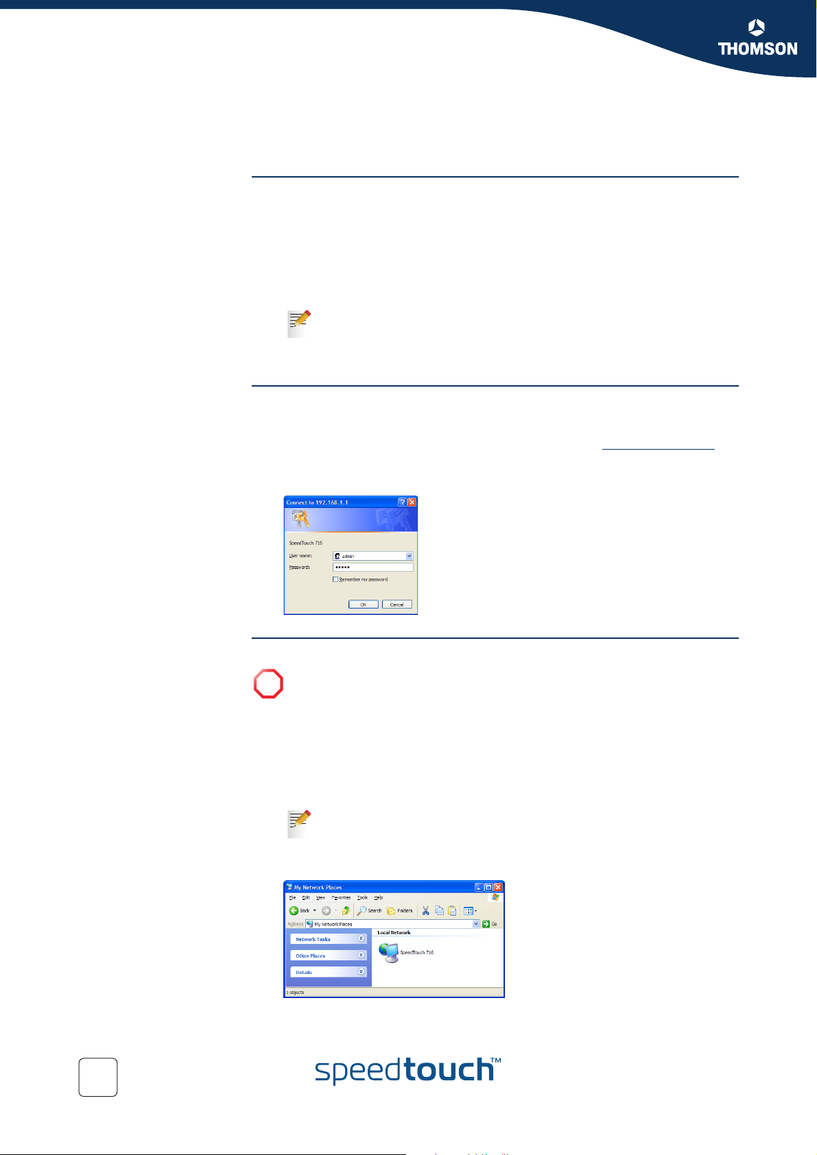
To access the SpeedTouch™ web pages:
1 Start the web browser on your computer.
2 Browse to the SpeedTouch™ at its IP address (default: http://192.168.1.254).
3 Type your SpeedTouch™’s User name (default: “admin”) and Password
(default: “admin”) and click OK to access the SpeedTouch™ web pages:
If your computer runs Windows XP Service Pack 2 (SP2) and you are using
!
the Windows Firewall, make sure the Windows Firewall allows incoming
network connections for the UPnP service (see “ Windows firewall
configuration” on page 100).
If your computer is UPnP™ enabled you can access the SpeedTouch™ web pages
as follows:
1 Click (Settings >) Control Panel on the Start menu to open the Control Panel.
2 Go to Network and Internet Connections > My Network Places.
If you use the Control Panel in Classic View, click Network
Connections in the Control Panel and My Network Places under Other
Places.
3 The following window appears:
44
Double-click the SpeedTouch™ icon.
E-DOC-CTC-20041126-0014 v3.0
Page 47
Chapter 5
SpeedTouch™ Web Interface
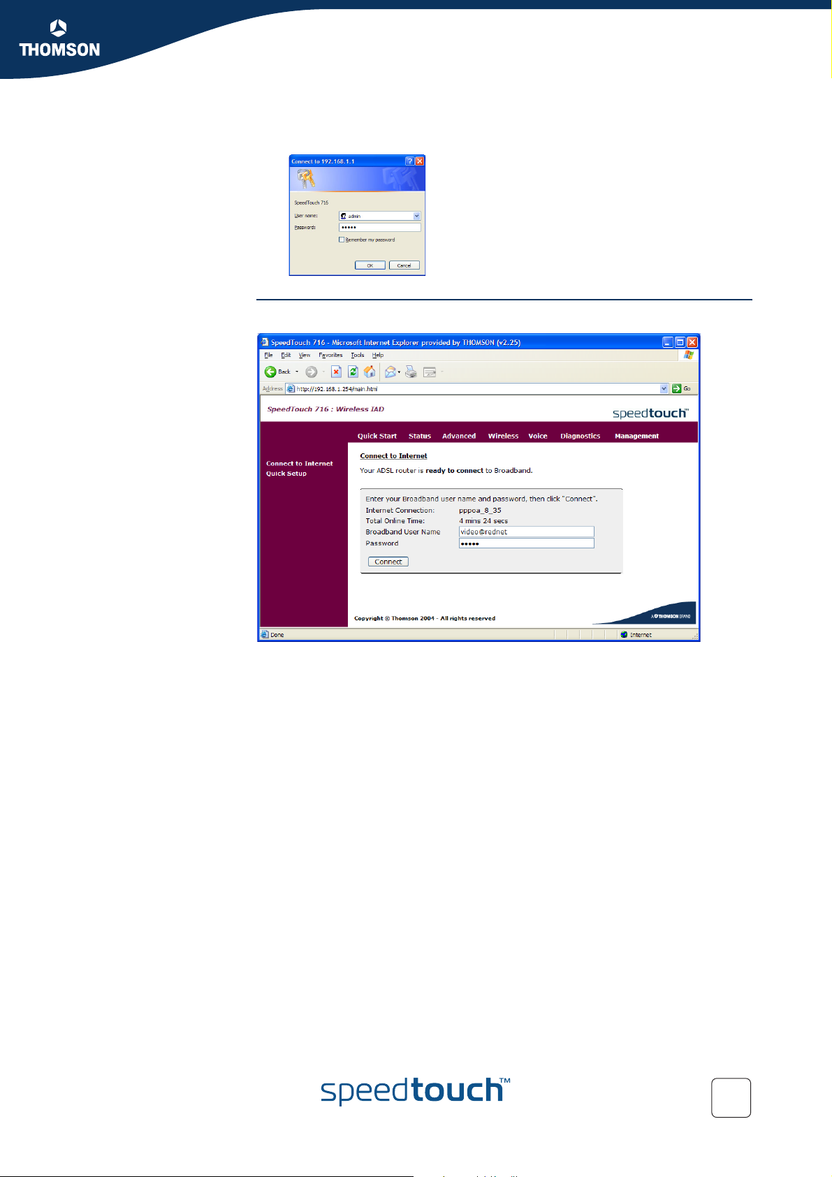
4 Type User name (default: “admin”) and password (default: “admin”) and click
OK to access the SpeedTouch™ web pages:
The SpeedTouch™
start page
As a result the Connect to Internet page appears:
E-DOC-CTC-20041126-0014 v3.0
45
Page 48
Chapter 5
SpeedTouch™ Web Interface
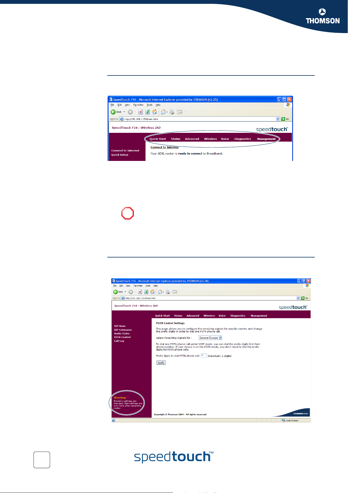
Topic menu and links With the help of this menu you can navigate through all configurable aspects of the
5.2 Navigating the SpeedTouch™ Web Pages
SpeedTouch™.
The SpeedTouch™ web pages are grouped into following categories:
Quick Start
Status
Advanced
Wireless
This link is only available if you purchased a SpeedTouch™716g.
!
Voic e
Diagnostics
Management
Applying new settings In some cases, it is required to reboot your SpeedTouch™ to apply your changes. If
this is the case, a message will be shown in the bottom left corner:
46
E-DOC-CTC-20041126-0014 v3.0
Page 49
5.3 Quick Start
The Quick Start menu The Quick Start menu consists of following submenus:
The Connect to Internet page
The Quick Setup page
Chapter 5
SpeedTouch™ Web Interface
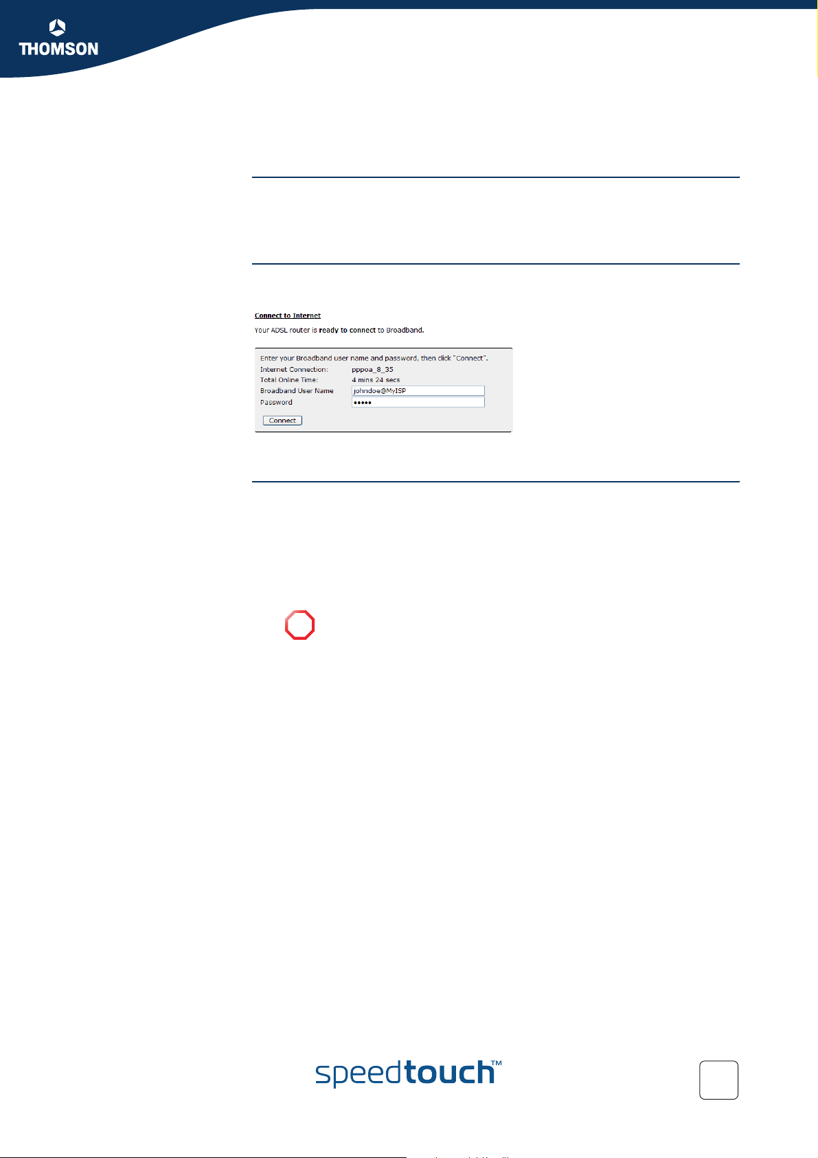
The Connect to Internet
page
The Quick Setup page The Quick Setup wizard guides you through the configuration of your Internet
The Connect to Internet page allows you to establish dial-in connections, if
applicable:
For more information, see “4.2 Using the SpeedTouch™ Web Pages” on page 42.
connection. During the configuration procedure following windows will appear:
ATM PVC
Connection type
WAN IP settings
PPP user name and password
This page will only be shown if you choose PPPoA or PPPoE as
!
connection type.
Configure LAN side settings
Summary
E-DOC-CTC-20041126-0014 v3.0
47
Page 50
Chapter 5
SpeedTouch™ Web Interface
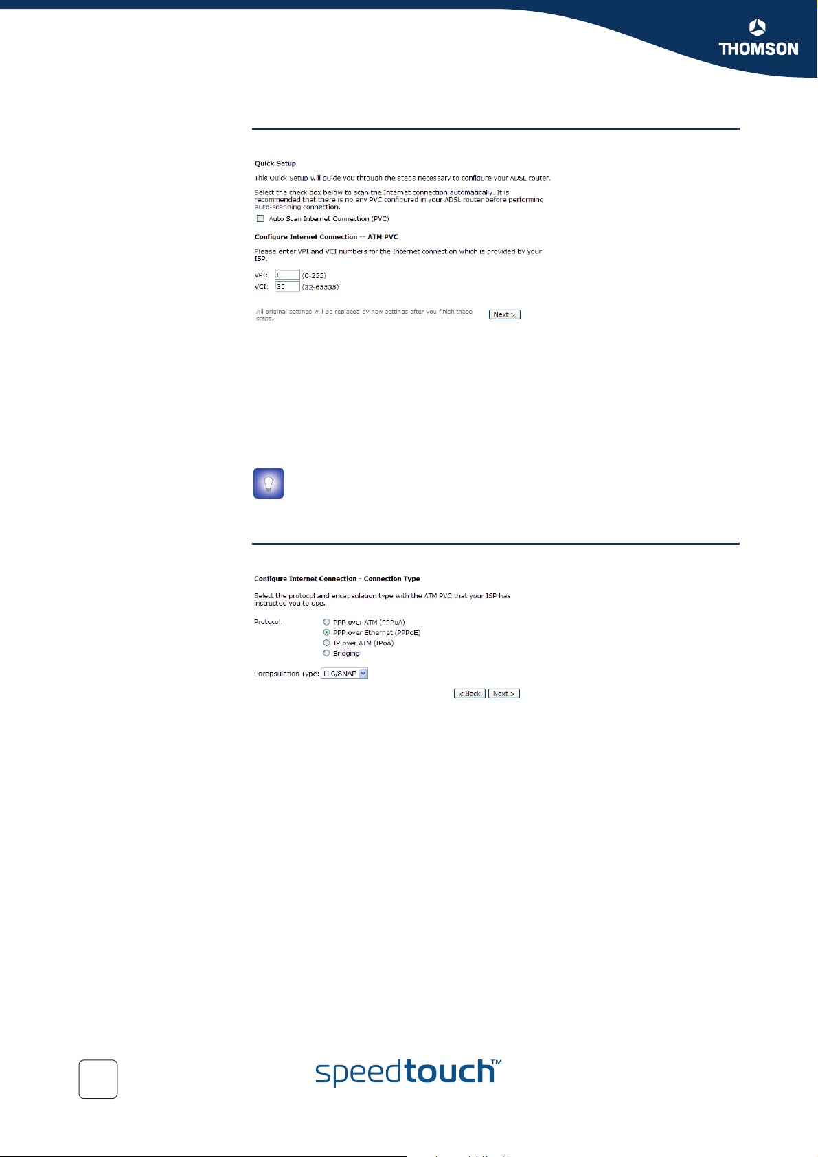
ATM PVC The ATM PVC section allows you to configure the VPI/VCI settings:
Following fields are available:
VPI (Virtual Path Identifier):
Identifies the virtual path between endpoints in an ATM network. The valid
range is from 0 to 255.
VCI (Virtual Channel Identifier):
Identifies the virtual channel endpoints in an ATM network. The valid range is
from 32 to 65535.
If you do not know which VPI/VCI you should use, select the Auto Scan
Internet Connection (PVC) check box to determine the correct value.
Enter the values provided by your ISP and click Next.
Connection type The Connection Type page allows you to select your connection type:
To configure your connection type:
1 In the Protocol dialog box, select the protocol provided by your ISP (for
example PPPoE).
2 In the Encapsulation list, click the Encapsulation type provided by your ISP (for
example LLC/SNAP).
3 Click Next to continue.
48
E-DOC-CTC-20041126-0014 v3.0
Page 51
SpeedTouch™ Web Interface
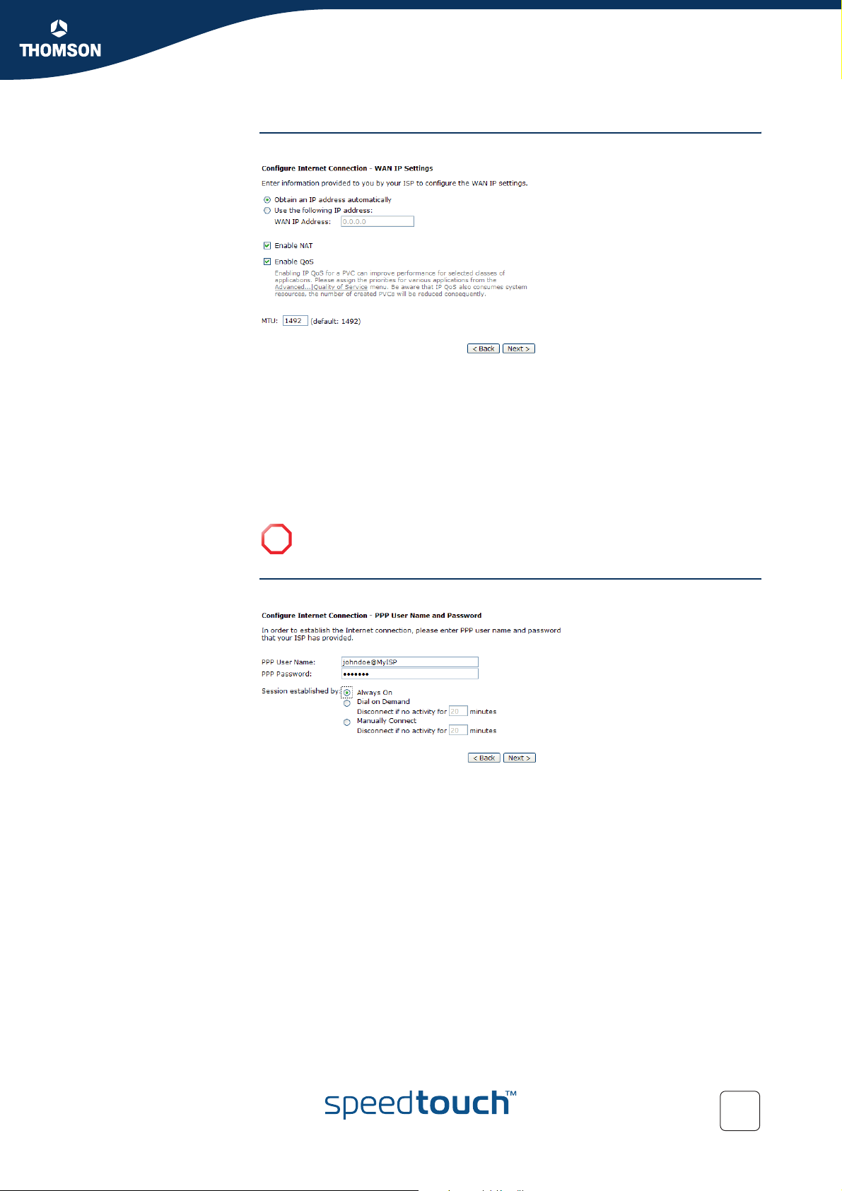
WAN IP settings The WAN IP Settings page allows you to configure the WAN IP settings:
Click:
Obtain an IP address automatically if your ISP wants you to get a dynamic IP
address.
Use the following IP address if your ISP has provided you with a static IP
address.
Enable NAT to enable Network Address Translation (NAT).
Enable QoS to enable Quality of Service (QoS).
The MTU box allows you to change the Maximum Transmission Unit (MTU).
Chapter 5
PPP user name and
password
Do not change the default MTU setting unless specifically asked by your ISP.
!
If you are configuring a PPPoE or PPPoA connection following window will appear:
Following fields are available:
PPP User Name:
Type the user name provided by your ISP.
PPP Password:
Type the password provided by your ISP.
Always On:
Click this option to make sure the connection is always active.
Dial on Demand:
Click this option to make a connection on demand. Enter the timeout to cut off
the network connection if there is no activity for this router.
E-DOC-CTC-20041126-0014 v3.0
49
Page 52
Chapter 5
SpeedTouch™ Web Interface
Manually Connect:
Click this option if you want to connect to the Internet via the SpeedTouch™
web pages. Enter the timeout to cut off the network connection if there is no
activity for this router.
For more information, see “ The Connect to Internet page” on
page 47.
Please type the user name and password provided by your ISP and click Next.
Configure LAN side
settings
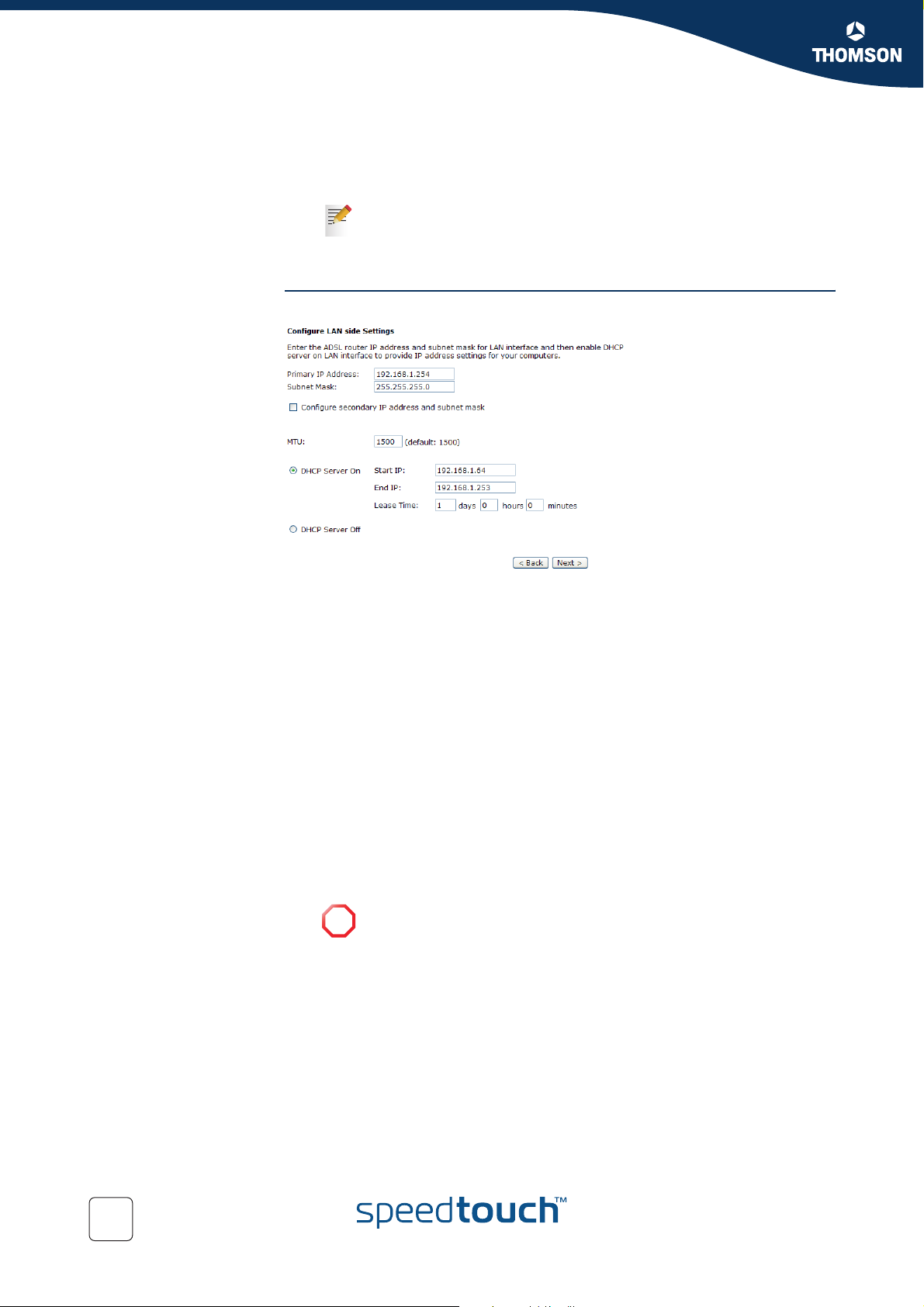
The Configure LAN side Settings page appears:
This page allows you to:
Change the LAN IP address of the SpeedTouch™.
Following fields are available:
Primary IP Address:
Enter the first IP address for your LAN connection.
Subnet Mask:
Enter the subnet mask for your LAN connection.
Configure the secondary IP Address and Subnet Mask:
Select this check box to make another set of IP Address and Subnet Mask
to connect to your router if they are not included in the range that DHCP
server accepts.
Secondary IP Address:
Enter the second IP address for your LAN connection.
Subnet Mask:
Enter the subnet mask for your LAN connection.
Change the Maximum Transmission Unit (MTU).
Do not change the default MTU setting unless specifically asked by
!
your ISP.
50
E-DOC-CTC-20041126-0014 v3.0
Page 53
SpeedTouch™ Web Interface
Configure the DHCP settings of the SpeedTouch™. Following fields are
available
DHCP Server On:
Click this option if you want the SpeedTouch™ to assign IP addresses to
the devices connected to the SpeedTouch™ network. Following fields
will become available:
Start IP Address:
Enter the start point IP address for the pool of IP addresses used by
your DHCP server.
End IP Address:
Enter the end point IP address for the pool of IP addresses used by
your DHCP server.
Leased Time (default: 1 day):
Enter the time for which you want to assign the IP address.
Make sure that at least one of the LAN IP addresses has the same
!
subnet as these DHCP lease pool addresses.
DHCP Server Off:
Click this option if DHCP service is not needed on the LAN.
Enter all the necessary settings and click Next for next page.
Chapter 5
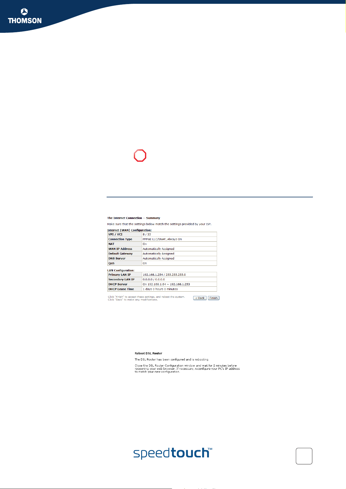
Summary At the end of the configuration procedure, the Quick Setup wizard summarizes your
settings:
If you want to:
Make changes to the listed configuration, click Back.
Apply your settings:
1 Click Finish to accept these settings.
2 The SpeedTouch™ will restart in order to apply your changes:
E-DOC-CTC-20041126-0014 v3.0
3 Wait for 2 minutes before restarting your browser.
51
Page 54
Chapter 5
SpeedTouch™ Web Interface
The Status menu The Status section consists of following pages:
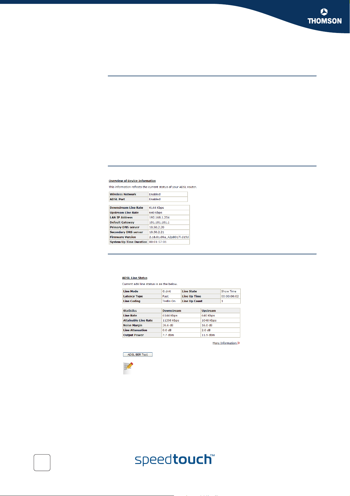
The Overview page The Overview page allows you to view the current status of the DSL connection:
5.4 Status
The Overview page
The ADSL Line Status page
The Internet Connection page
The Traffic Statistics page
The DHCP Table page
The Wireless Clients page
The Routing Table page
The ARP Table page
The ADSL Line Status
page
The ADSL Line Status page allows you to:
View all information on ADSL:
Click More Information to view more detailed statistics.
52
E-DOC-CTC-20041126-0014 v3.0
Page 55
SpeedTouch™ Web Interface
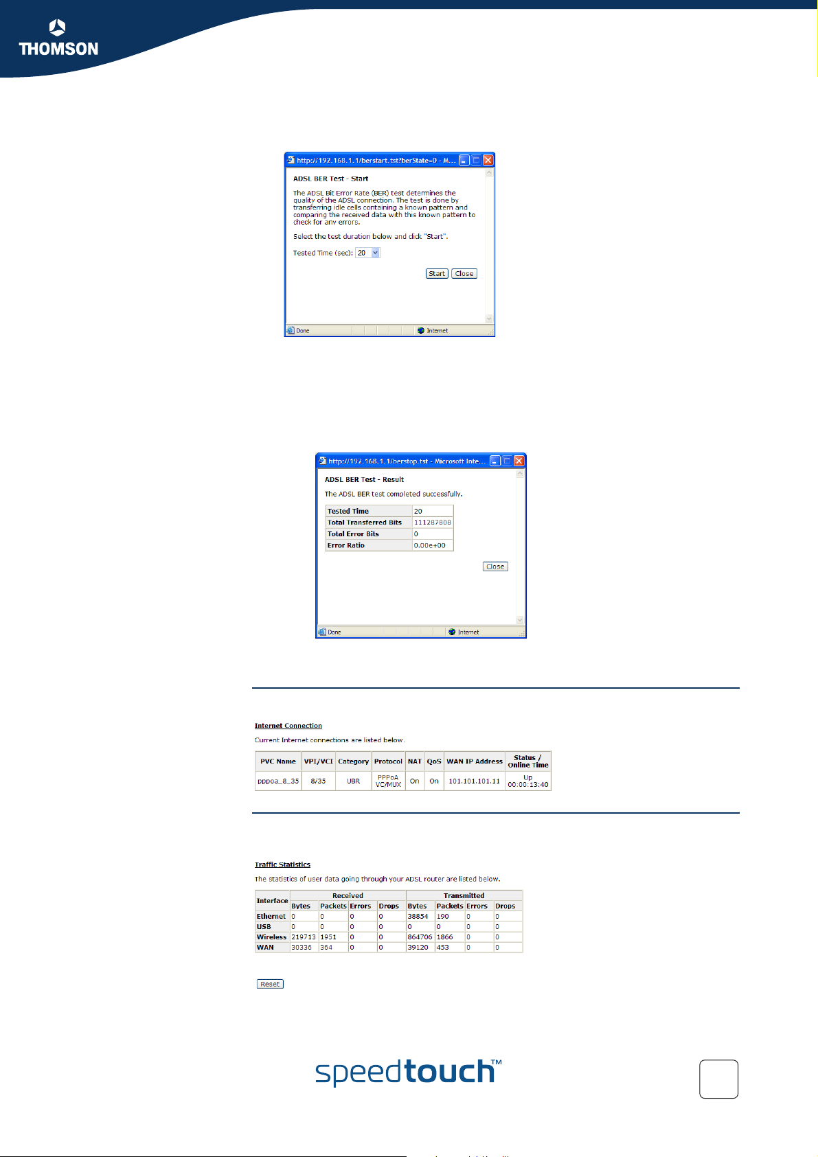
Click the ADSL BER Test button to determine the quality of your ADSL
connection:
To start the ADSL Bit Error Rate (BER) test:
1 Select the duration time (in seconds) in the Tested Time list.
2 Click Start.
3 The SpeedTouch™ runs the ADSL BER test.
4 At the end of the test, the results are listed in following window:
Chapter 5
The Internet Connection
page
The Traffic Statistics
page
5 Click Close to close this window.
This page allows you to view the connection information of your SpeedTouch™:
This page allows you to view the records of data going through the LAN and WAN
interface:
E-DOC-CTC-20041126-0014 v3.0
53
Page 56
Chapter 5
SpeedTouch™ Web Interface
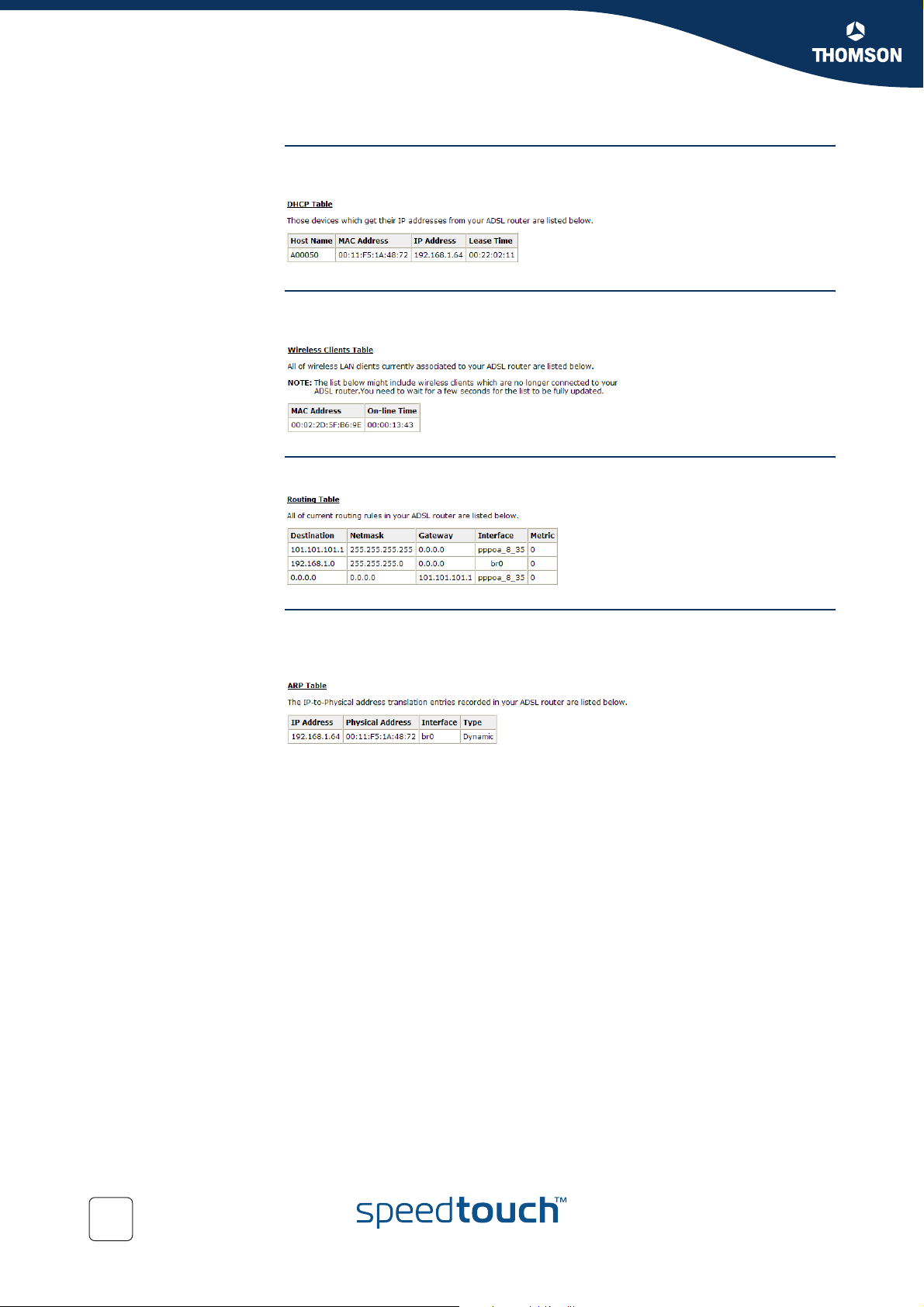
The DHCP Table page This page lists the current IP address leases provided by the SpeedTouch™ DHCP
server:
The Wireless Clients
page
This page lists the wireless clients currently associated to the SpeedTouch™ Access
Point:
The Routing Table page This page shows the static routes used by the SpeedTouch™ IP router:
The ARP Table page This page shows the Address Resolution Protocol (ARP) table used by the
SpeedTouch™ to translate the IP address of a host connected to the SpeedTouch™
into a physical addresses:
54
E-DOC-CTC-20041126-0014 v3.0
Page 57

5.5 Advanced
The Advanced menu The Advanced menu consists of the following submenus:
Local Network
Internet
IP Routing
DNS Server
Virtual Server
Firewall
Quality of Service
IGMP Proxy
Chapter 5
SpeedTouch™ Web Interface
E-DOC-CTC-20041126-0014 v3.0
55
Page 58
Chapter 5
SpeedTouch™ Web Interface
5.5.1 Local Network
The Local Network
menu
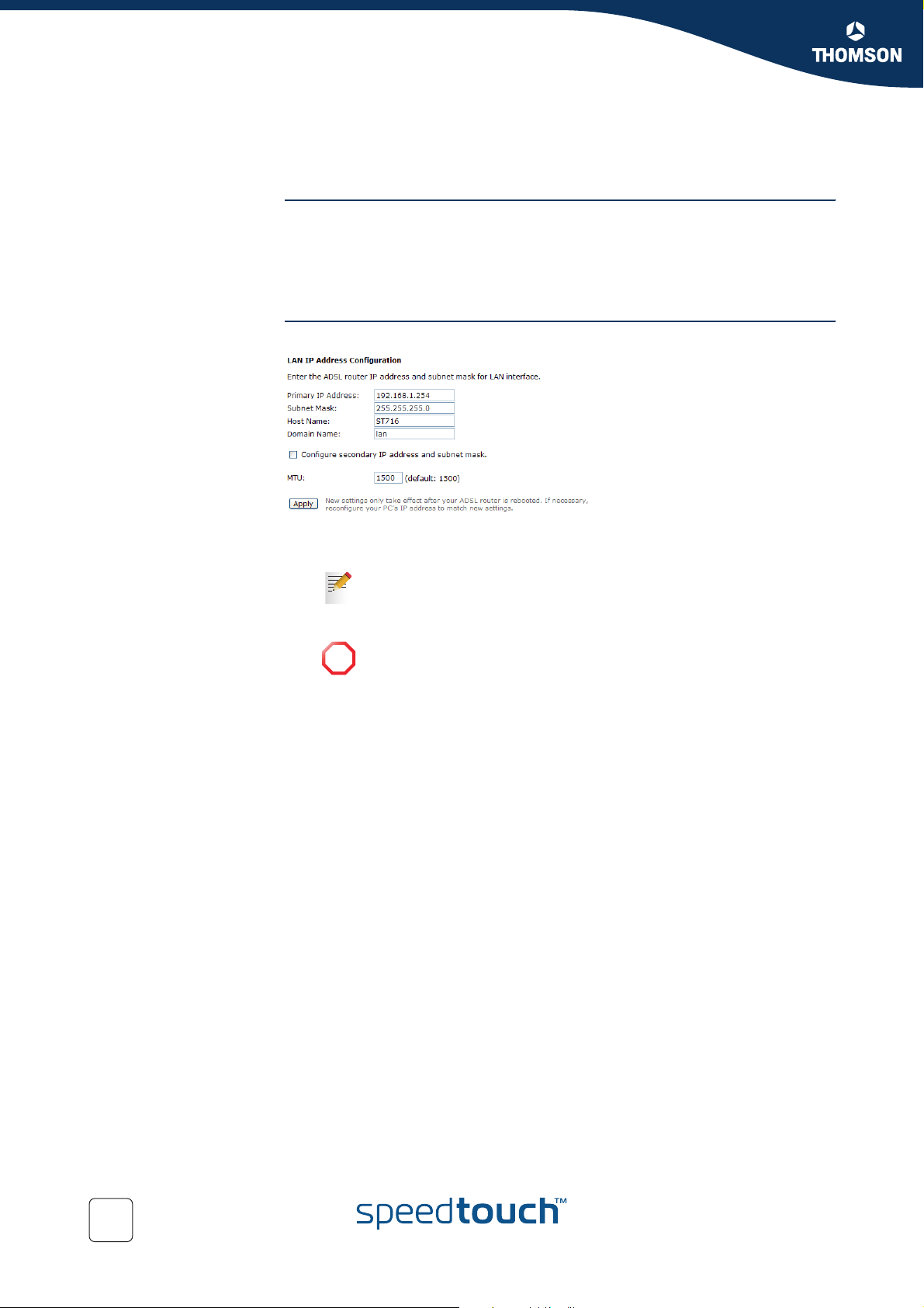
The IP Address page Following figure shows the LAN IP Address Configuration page:
The Local Network section consists of the following pages:
The IP Address page
The DHCP Server page
The UPnP page
This page allows you to configure:
The LAN IP address of the SpeedTouch™.
You can assign a second IP address to the SpeedTouch™, by selecting
the Configure secondary IP address and subnet mask check box.
Change the Maximum Transmission Unit (MTU).
Do not change the default MTU setting unless specifically asked by
!
your ISP.
A static DNS hostname for the SpeedTouch™:
Providing a static DNS hostname for the SpeedTouch™ allows you to address
the SpeedTouch™ not only by IP address but also by name (for example
“ST716.lan “).
56
E-DOC-CTC-20041126-0014 v3.0
Page 59
SpeedTouch™ Web Interface
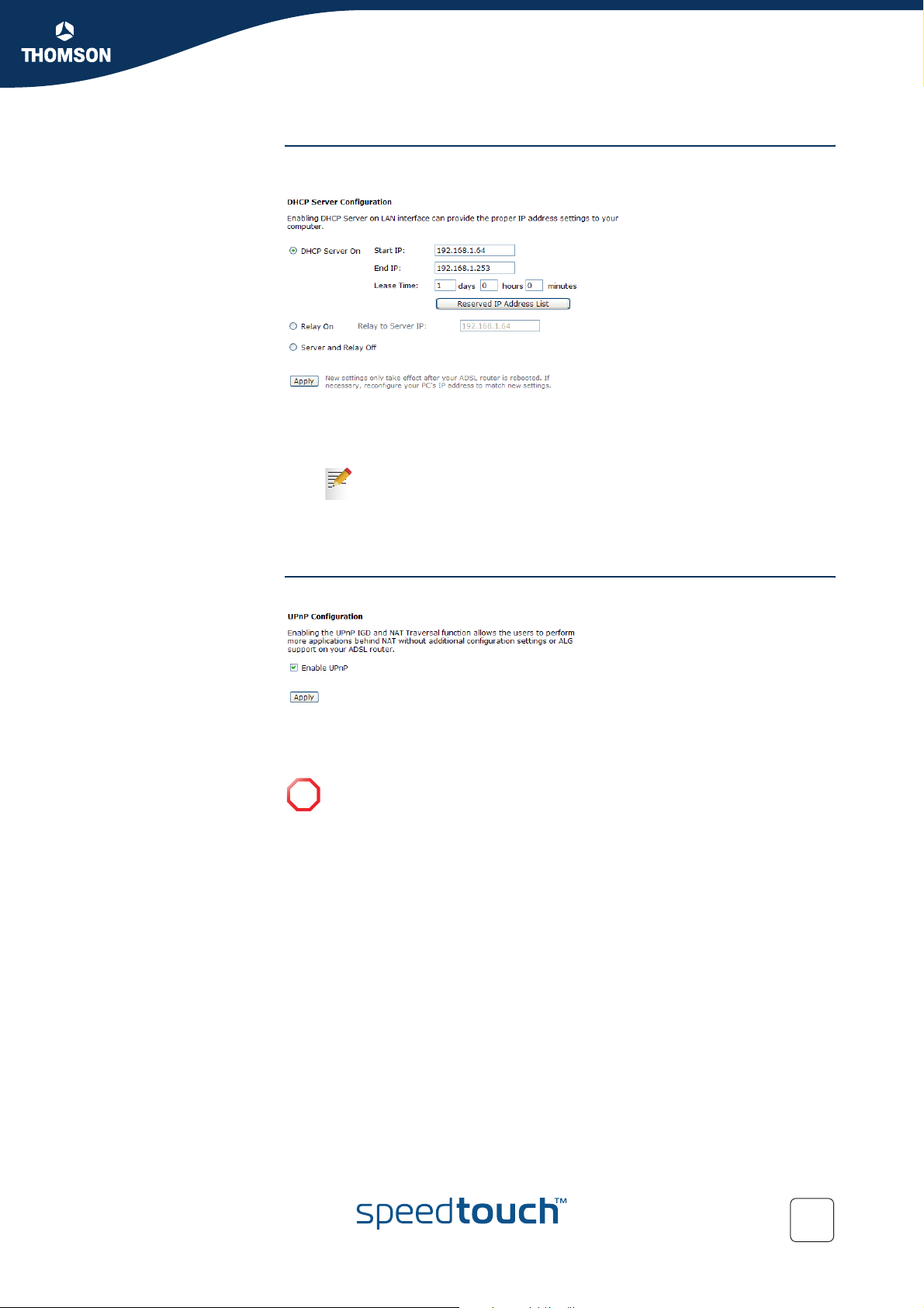
The DHCP Server page The DHCP Server Configuration page allows you to configure the SpeedTouch™
DHCP server:
Click:
DHCP Server On if DHCP service is needed on the LAN. The router will assign
IP address, gateway address for each of your PCs.
Click Reserved IP Address List to assign a static IP address to a
computer on your LAN.
Chapter 5
Relay On to use a DHCP server available on another network.
Server and Relay Off to disable the SpeedTouch™ DHCP server.
The UPnP page The UPnP page allows you to enable/disable UPnP:
If you select the Enable UPnP check box, all local hosts will be able to detect the
SpeedTouch™. Any local host will be able to create port mappings for any local
device.
If you want to use this feature, make sure that UPnP is correctly installed on
!
your computer. See “8.2 UPnP™ on Windows XP Systems” on page 99.
E-DOC-CTC-20041126-0014 v3.0
57
Page 60
Chapter 5
SpeedTouch™ Web Interface
5.5.2 Internet
The Internet menu The Internet section consists of the following pages:
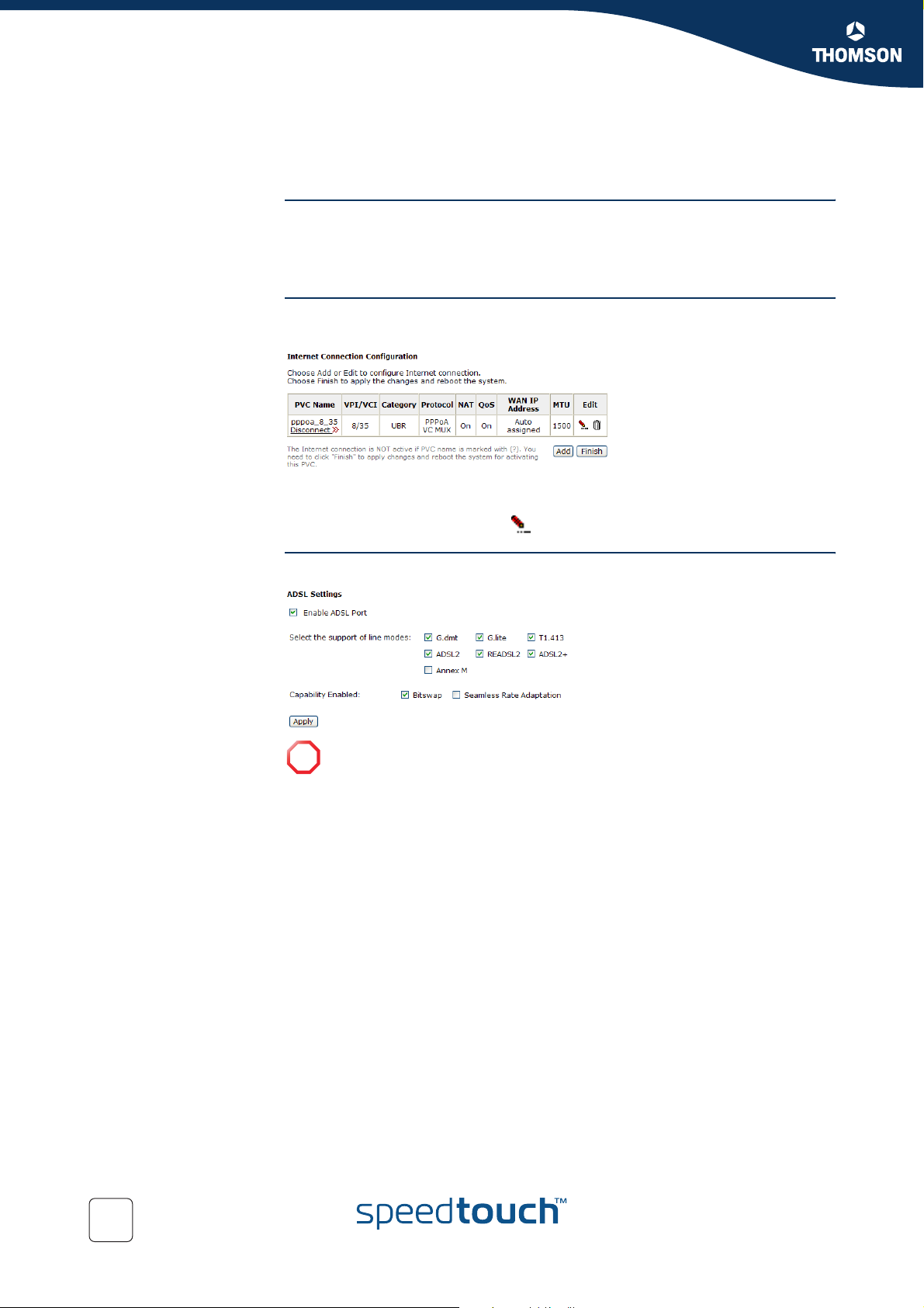
The Connection page The Internet Connection Configuration page allows you to view/change the WAN
The Connection page
The ADSL Settings page
settings for each service:
If you click the Connect link of the connection, the SpeedTouch™ will connect to the
WAN automatically.
To reconfigure a connection, click .
The ADSL Settings
page
This page allows you to view/change the ADSL settings:
This feature is for advanced users only.
!
58
E-DOC-CTC-20041126-0014 v3.0
Page 61
SpeedTouch™ Web Interface
5.5.3 IP Routing
The IP Routing menu The IP Routing menu consists of the following pages:
The Static Route page
The Dynamic Routing page
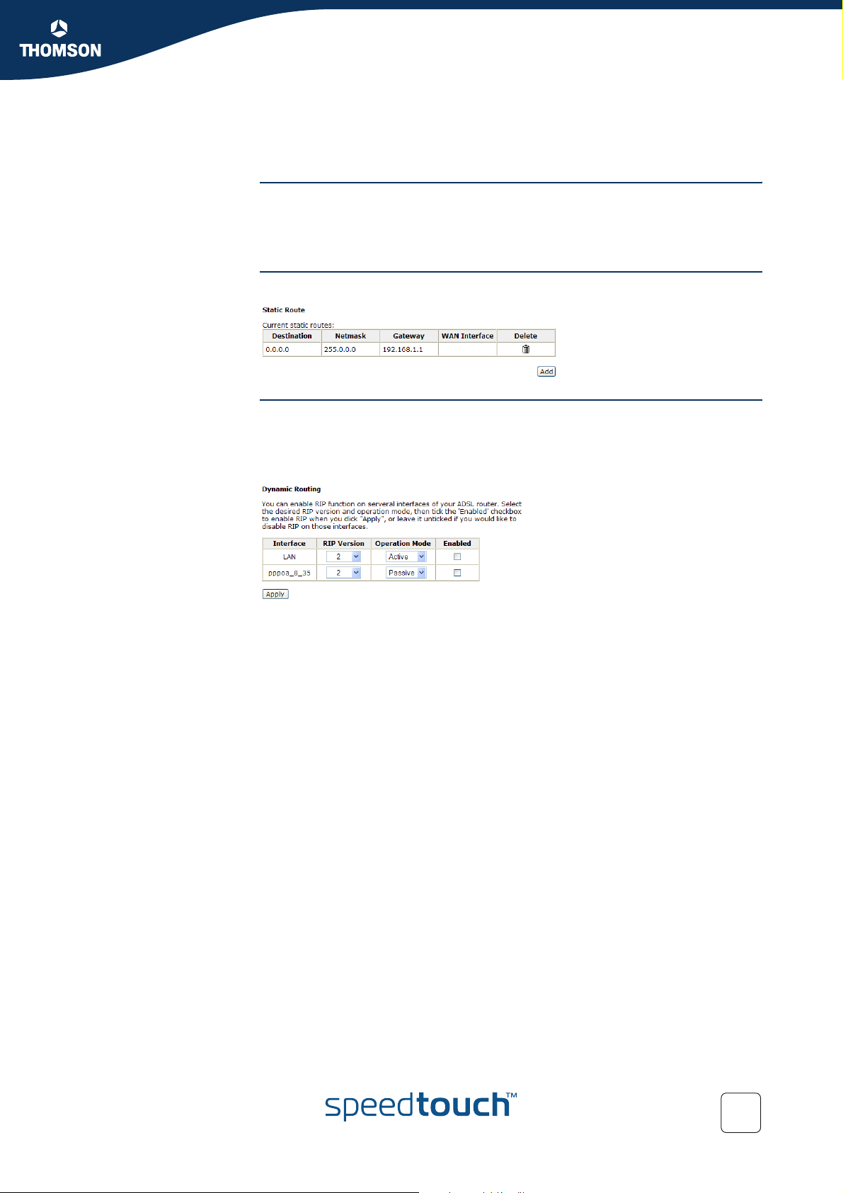
The Static Route page This page allows you to add/delete static routes for the SpeedTouch™ router:
Chapter 5
The Dynamic Routing
page
The Routing Information Protocol (RIP) is used to exchange routing information
between routers. This helps the routers to determine optimal routes.
The Dynamic Routing page allows you to enable/disable RIP on the SpeedTouch™
interfaces:
Following fields are available:
Ver sion:
It incorporates the RIP information when receiving and broadcasting the RIP
packets.
Operation:
Active to transmit and receive routing information from other routers.
Passive to only receive routing information from other routers.
Enabled:
You are able to enable/disable RIP for each interface.
E-DOC-CTC-20041126-0014 v3.0
59
Page 62
Chapter 5
SpeedTouch™ Web Interface
5.5.4 DNS Server
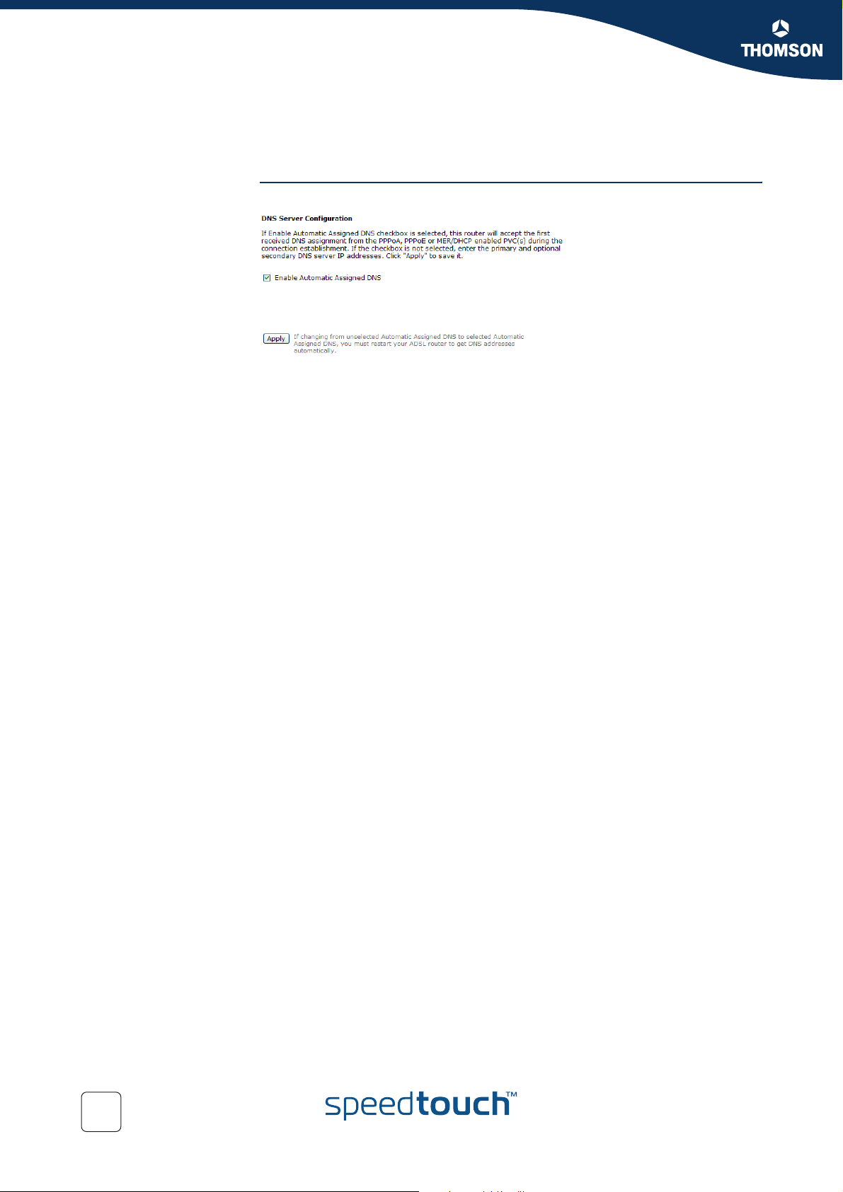
The DNS Server page The DNS Server Configuration page allows you to configure your DNS settings:
If Enable Automatic Assigned DNS check box is:
Selected:
The SpeedTouch™ will accept the first received DNS assignment from one of
the PPPoA, PPPoE or MER/DHCP enabled PVC(s) when establishing the
connection.
Cleared:
You must provide:
A Primary DNS Server IP address.
A Secondary DNS server IP address (optional).
60
E-DOC-CTC-20041126-0014 v3.0
Page 63
5.5.5 Virtual Server
Chapter 5
SpeedTouch™ Web Interface
The Virtual Server
menu
The Virtual Server section consists of following pages:
The Port Forwarding page
Port Triggering
DMZ Host
Dynamic DNS
The Port Forwarding
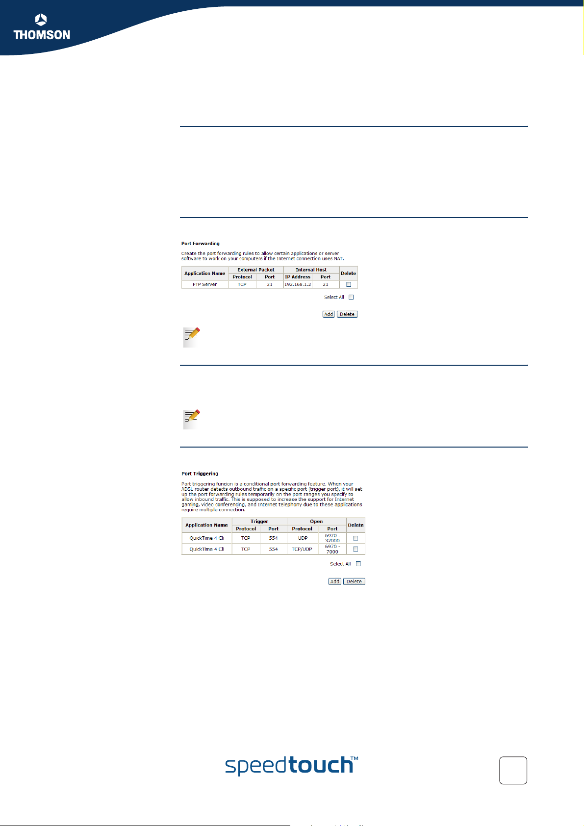
This page allows you to add/delete port forwarding rules:
page
For more information on port forwarding and virtual servers, see
“7.1 Setting up a Virtual Server” on page 92.
Port Triggering When the SpeedTouch™ detects outbound traffic on a port listed in the Port
Triggering table (a trigger port), it automatically creates the necessary port
forwarding rules to allow inbound traffic for this connection.
Port triggering is useful for the applications that need multiple connections
such as games and video conferencing.
The Port Triggering
page
The Port Triggering page allows you to add/delete port triggering rules:
E-DOC-CTC-20041126-0014 v3.0
61
Page 64
Chapter 5
SpeedTouch™ Web Interface
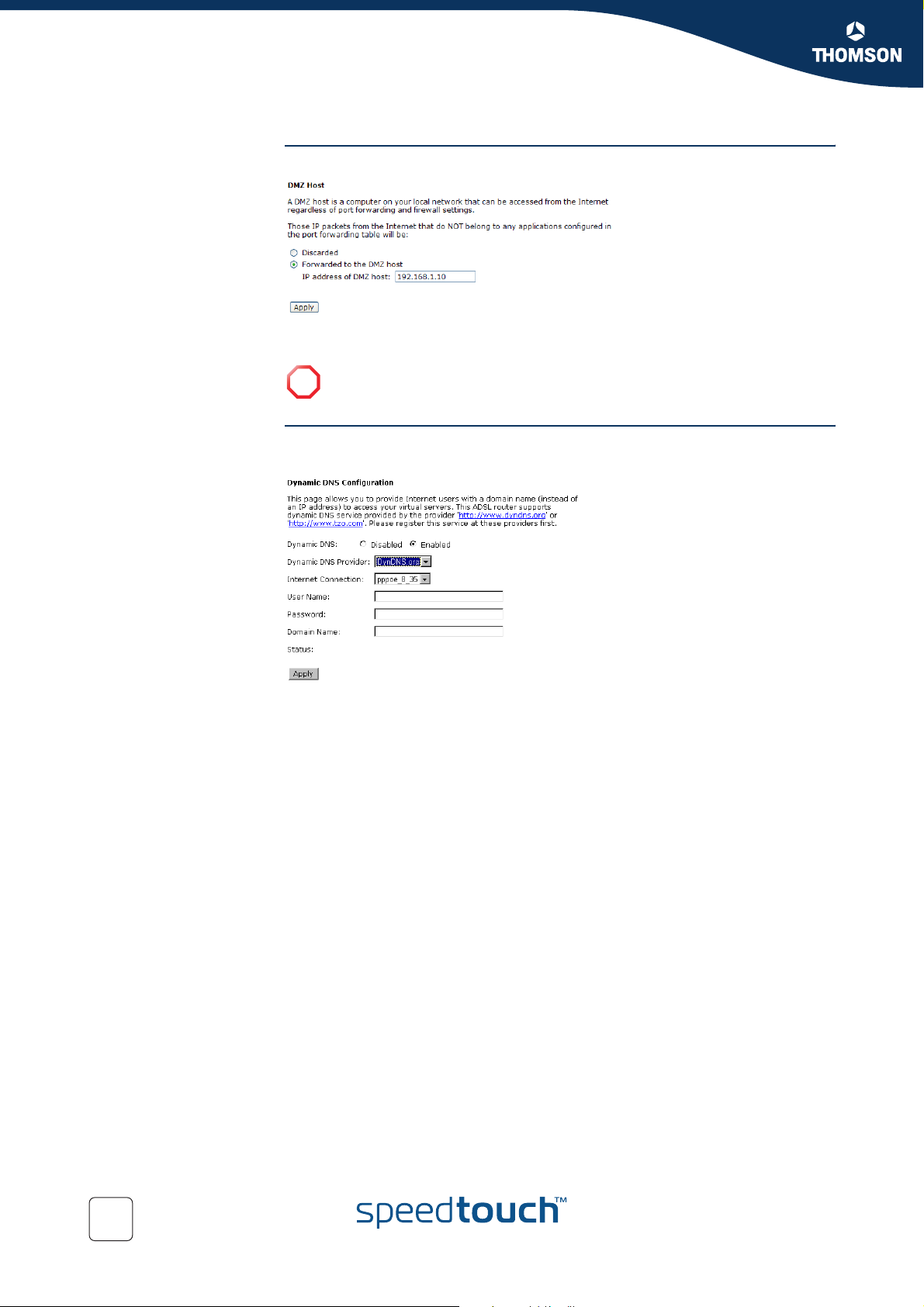
DMZ Host The DMZ host page allows you to specify a Direct Mapping Zone (DMZ) host:
Dynamic DNS This page allows Internet users to access your virtual servers using a domain name
All incoming connections that do not match any static or dynamic port forwarding
rule will be forwarded to this DMZ Host.
If you specify a DMZ host, make sure that this host is using a static IP
!
address.
instead of an IP address
62
E-DOC-CTC-20041126-0014 v3.0
Page 65
SpeedTouch™ Web Interface
5.5.6 Firewall
Basics Firewalls are computer network devices that protect a network from other less
trusted networks. They are essentially network access control devices that permit
and deny different types of traffic to travel into and out of an organization's
network. Most often, firewalls are placed at the network boundary to protect an
organization from malicious users on the Internet.
Firewall rules The SpeedTouch™ firewall can:
Deny or permit any packet from passing through explicitly.
Distinguish between various interfaces and match on the following fields:
Source and destination IP address
Port
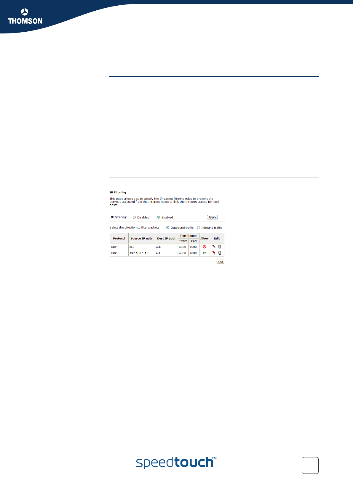
The IP Filtering page This page allows you to configure IP Filtering rules for the SpeedTouch™:
Chapter 5
E-DOC-CTC-20041126-0014 v3.0
63
Page 66
Chapter 5
SpeedTouch™ Web Interface
5.5.7 Quality of Service
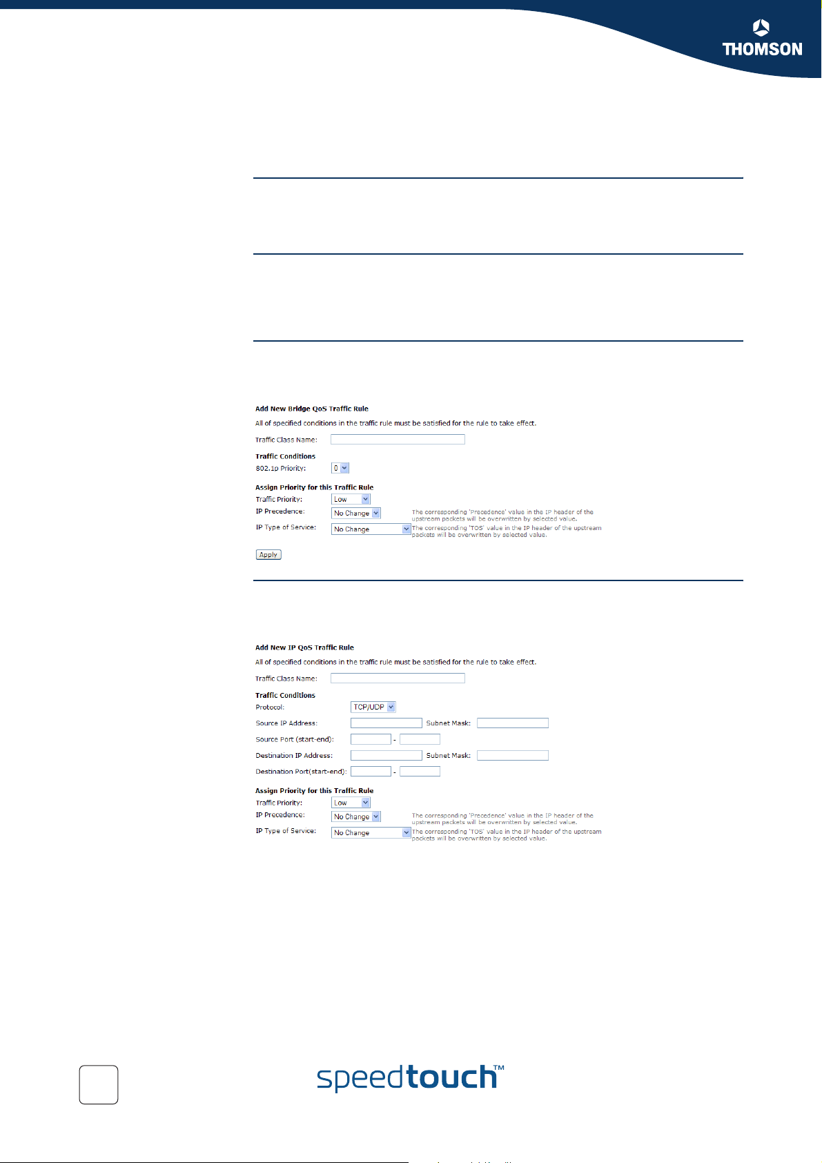
QoS Quality of Service (QoS) is an industry-wide initiative to provide preferential
treatment to certain subsets of data, enabling those data to traverse the Internet or
intranet with higher quality transmission service.
The Quality of Service
menu
The Quality of Service section consists of following pages:
The Bridge QoS page
The IP QoS page
The Bridge QoS page The Bridge QoS page allows you to classify the upstream traffic (to the Internet) by
assigning the transmission priority for various user data. The Bridge QoS function
prioritizes the data transmission based on layer 2 bridge packets:
The IP QoS page The IP QoS page allows you to classify the upstream traffic (to the Internet) by
assigning the transmission priority for various user data. The IP QoS function
prioritizes the data transmission based on layer 3 IP packets:
64
E-DOC-CTC-20041126-0014 v3.0
Page 67
Chapter 5
SpeedTouch™ Web Interface
5.5.8 IGMP Proxy
IGMP The Internet Group Management Protocol (IGMP) is an Internet protocol that
enables an Internet computer to report its multicast group membership to adjacent
routers by means of IGMP messages.
IGMP proxy However, when acting as a proxy, the system performs the host portion of the IGMP
task as follows:
When it is queried, the system will send group membership reports to the
group.
When one of the hosts joins a multicast address group to which none of the
other hosts belong, the system will send unsolicited group membership
reports to that group.
When the last hosts in a particular multicast group leaves the group, the
system will send a leave group membership report to the routers group.
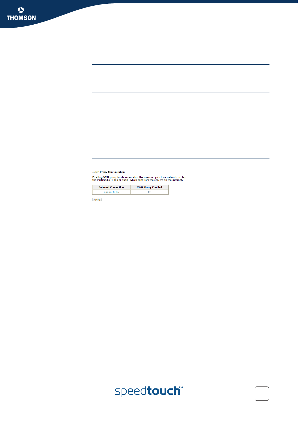
The IGMP Proxy
Configuration page
The IGMP Proxy Configuration page allows you to enable/disable the IGMP proxy:
E-DOC-CTC-20041126-0014 v3.0
65
Page 68
Chapter 5
SpeedTouch™ Web Interface
Availability
5.6 Wireless
This menu item is only available if you purchased a SpeedTouch™716g.
!
Wireless basics
Navigation Following menu items are available on the Wireless menu:
For more information on wireless networking basics, see “2.3 Wireless Connection
Setup” on page 19.
Basic
Security
Access Control
Repeater
66
E-DOC-CTC-20041126-0014 v3.0
Page 69
5.6.1 Basic
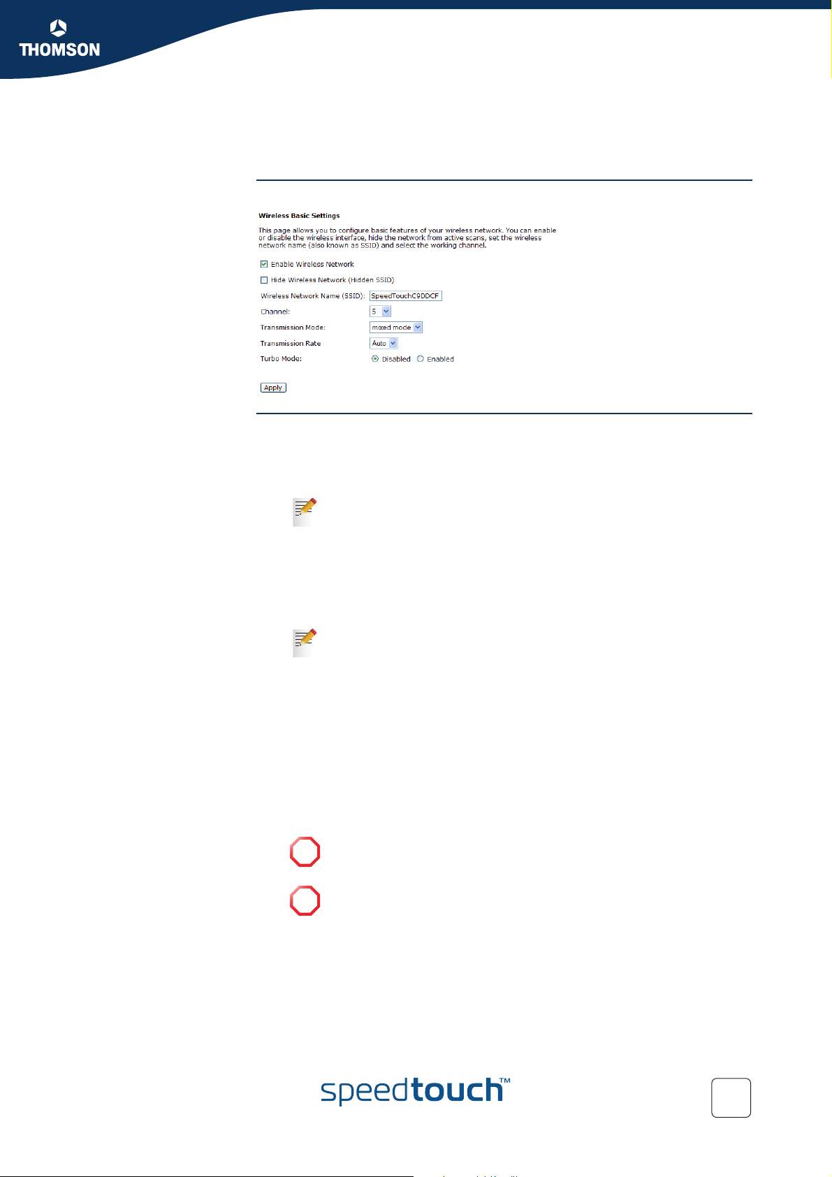
The Basic page Following figure shows you the Wireless Basic Settings page:
Chapter 5
SpeedTouch™ Web Interface
Configuring the
SpeedTouch™ Access
Point
If the Enable Wireless Network check box is selected, following fields are available:
Hide Wireless Network:
Select this check box to prevent the SpeedTouch™ from broadcasting it’s
SSID.
For more information, see “2.4.7 Hiding your Wireless Network” on
page 34.
Wireless Network Name (SSID):
The network name of your wireless network.
Channel:
The frequency in which the radio links are about to be established. Select one
channel that you want from the drop-down list.
For more information on the use of radio channels, see “Radio
channels” on page 19.
Transmission Mode:
Following modes are available:
802.11b only
802.11g only
Mixed Mode
Click this mode to allow both IEEE802.11b and IEEE802.11g clients.
Transmission Rate:
This list allows you to configure the transmission rate of your wireless
connection.
Take into consideration that if the distance between the SpeedTouch™
!
and the wireless client increases, the throughput for this wireless
client decreases.
If Mixed Mode is selected in the Transmission Mode list, you can not
!
manually specify a transmission rate.
E-DOC-CTC-20041126-0014 v3.0
Turbo Mode:
Check Enabled to invoke this function for speeding up the transmission, or
check Disabled to close this function.
67
Page 70
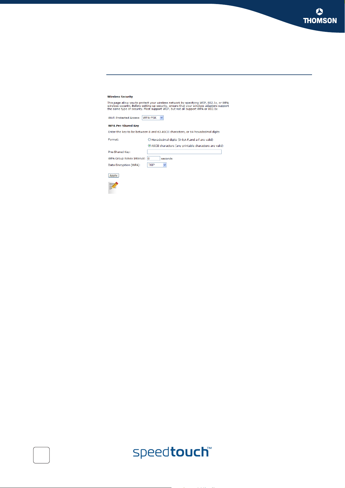
Chapter 5
SpeedTouch™ Web Interface
5.6.2 Security
The Security page The security page allows you to choose an encryption method for data sent over the
SpeedTouch™ wireless network:
For more information, see “2.4.1 Encryption” on page 25.
68
E-DOC-CTC-20041126-0014 v3.0
Page 71
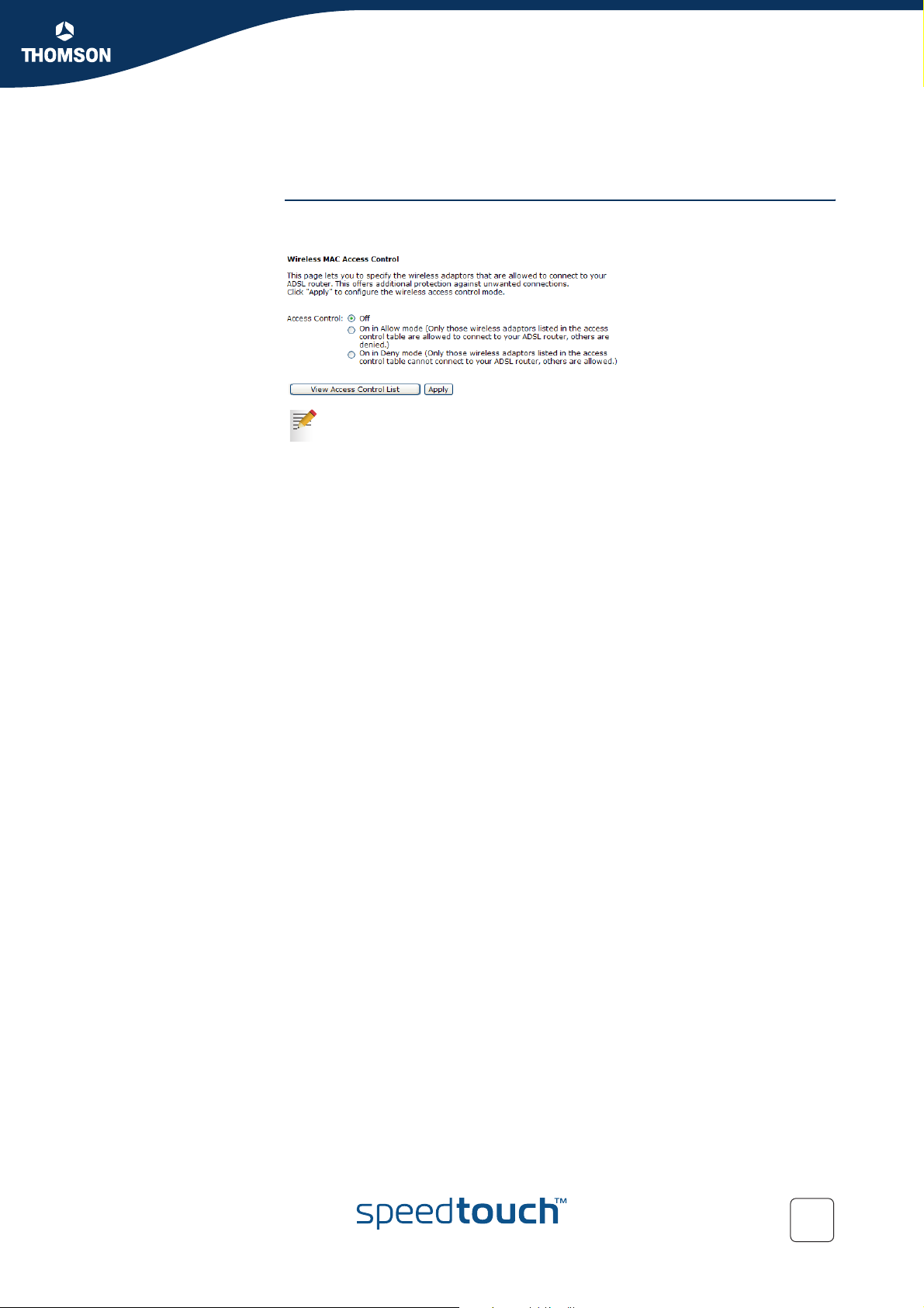
5.6.3 Access Control
Chapter 5
SpeedTouch™ Web Interface
The Access Control
page
The Wireless MAC Access Control page allows you to enable the wireless MAC
control configuration:
For more information, see “2.4.6 Restricting Wireless Access” on page 33.
E-DOC-CTC-20041126-0014 v3.0
69
Page 72
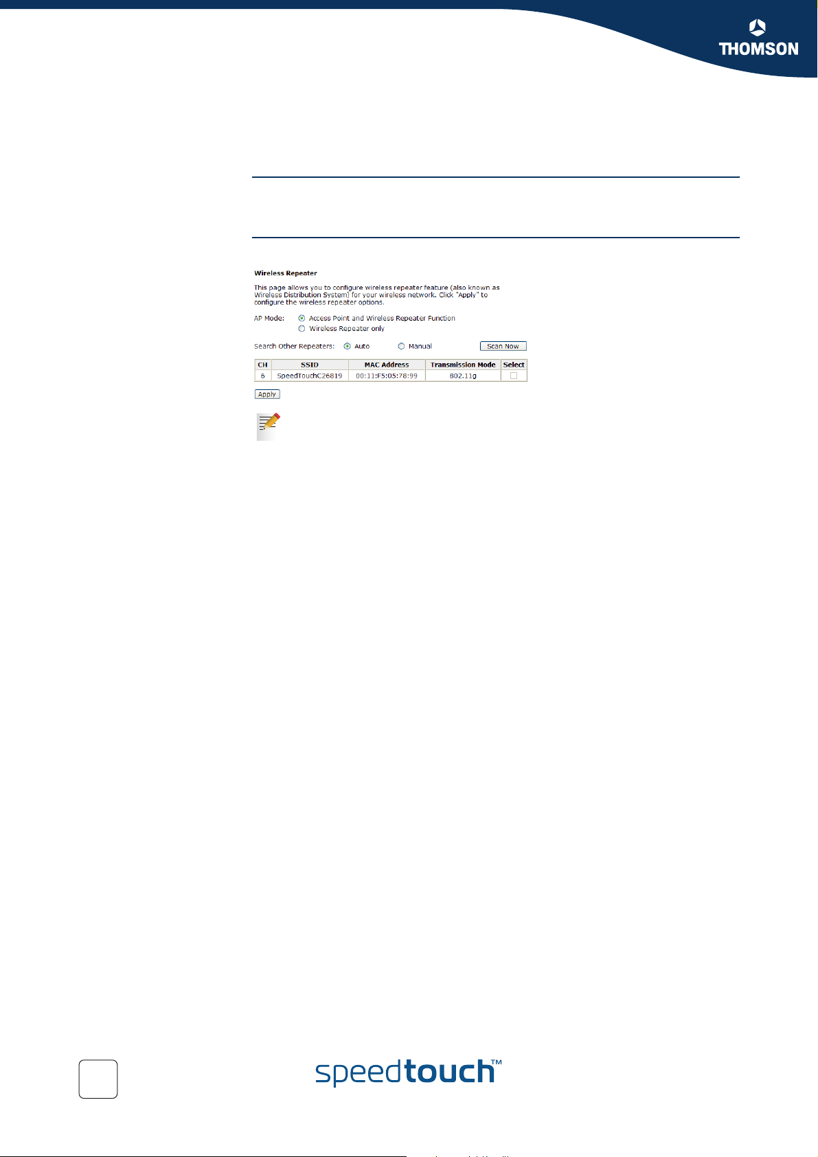
Chapter 5
SpeedTouch™ Web Interface
5.6.4 Repeater
WDS functionality The Wireless Distribution System (WDS) allows you to extend the range of your
The Repeater page The Repeater page allows you to configure a WDS link with other Access Points:
SpeedTouch™716g by means of one or more wireless repeaters.
For more information, see “2.5 Extending the Range of your Wireless
Network” on page 35.
70
E-DOC-CTC-20041126-0014 v3.0
Page 73

SpeedTouch™ Web Interface
5.7 Voice
Protocols Depending on the SpeedTouch™ variant you purchased, one of the following
protocols are used for Voice over IP (VoIP):
Session Initiation Protocol (SIP)
For more information on the SIP web pages, see “6.1.2 SIP Web Pages” on
page 81.
Media Gateway Control Protocol (MGCP)
For more information on the MGCP web pages, see “6.2.2 MGCP Web Pages”
on page 86.
Chapter 5
E-DOC-CTC-20041126-0014 v3.0
71
Page 74
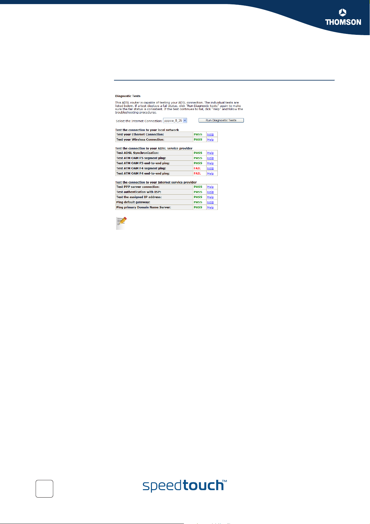
Chapter 5
SpeedTouch™ Web Interface
The Diagnostics page The Diagnostics page allows you to check the SpeedTouch™ connections:
5.8 Diagnostics
For more information, see “8.4.1 Diagnostics Tests” on page 104.
72
E-DOC-CTC-20041126-0014 v3.0
Page 75
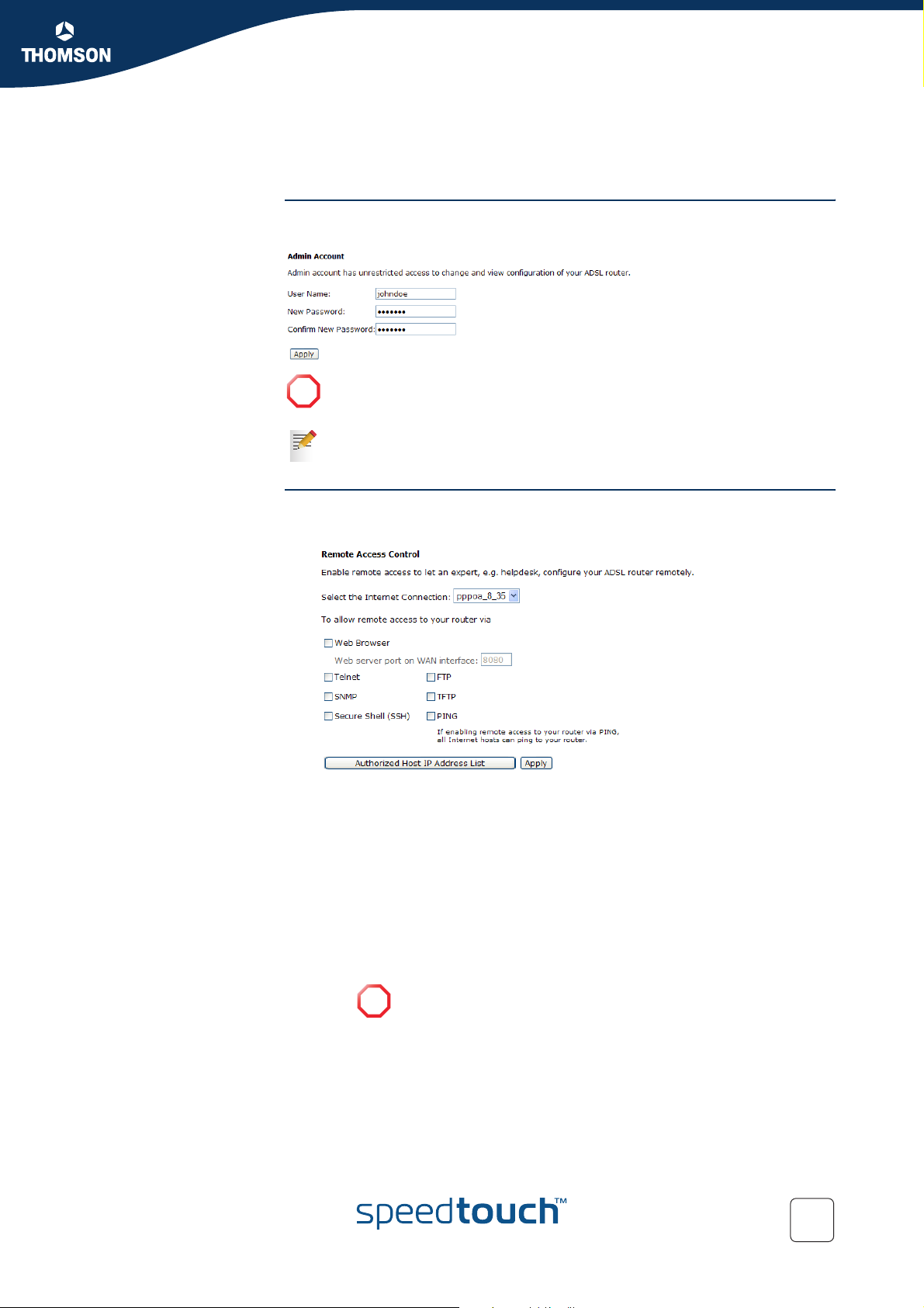
SpeedTouch™ Web Interface
5.9 Management
Admin Account The Admin Account page allows you to configure a system password to restrict
access to the SpeedTouch™:
It is highly recommended to configure a system password, to protect the
!
SpeedTouch™. Make sure however not to use an obvious password such as
your name, date of birth and so on.
The default value for the User name and password is “admin”.
Chapter 5
Remote Access The Remote Access Control page allows you to:
Configure Remote Access methods:
Following access methods are supported:
Web Browser
Tel ne t:
SNMP:
Secure Shell (SSH):
FTP :
TFTP:
Ping:
If you choose this selection, all Internet hosts can ping to your
!
router without any difficulty.
E-DOC-CTC-20041126-0014 v3.0
73
Page 76
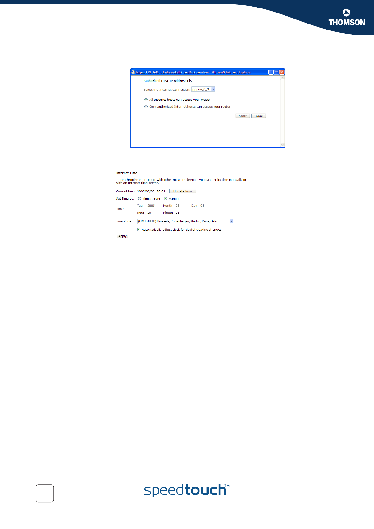
Chapter 5
SpeedTouch™ Web Interface
Internet Time This page allows you to adjust the time used in the syslog and call log pages:
Click Authorized Host IP Address List to configure which users are allowed to
use remote access the SpeedTouch™:
You are able to set the time:
Manually
By means of a time server
74
E-DOC-CTC-20041126-0014 v3.0
Page 77
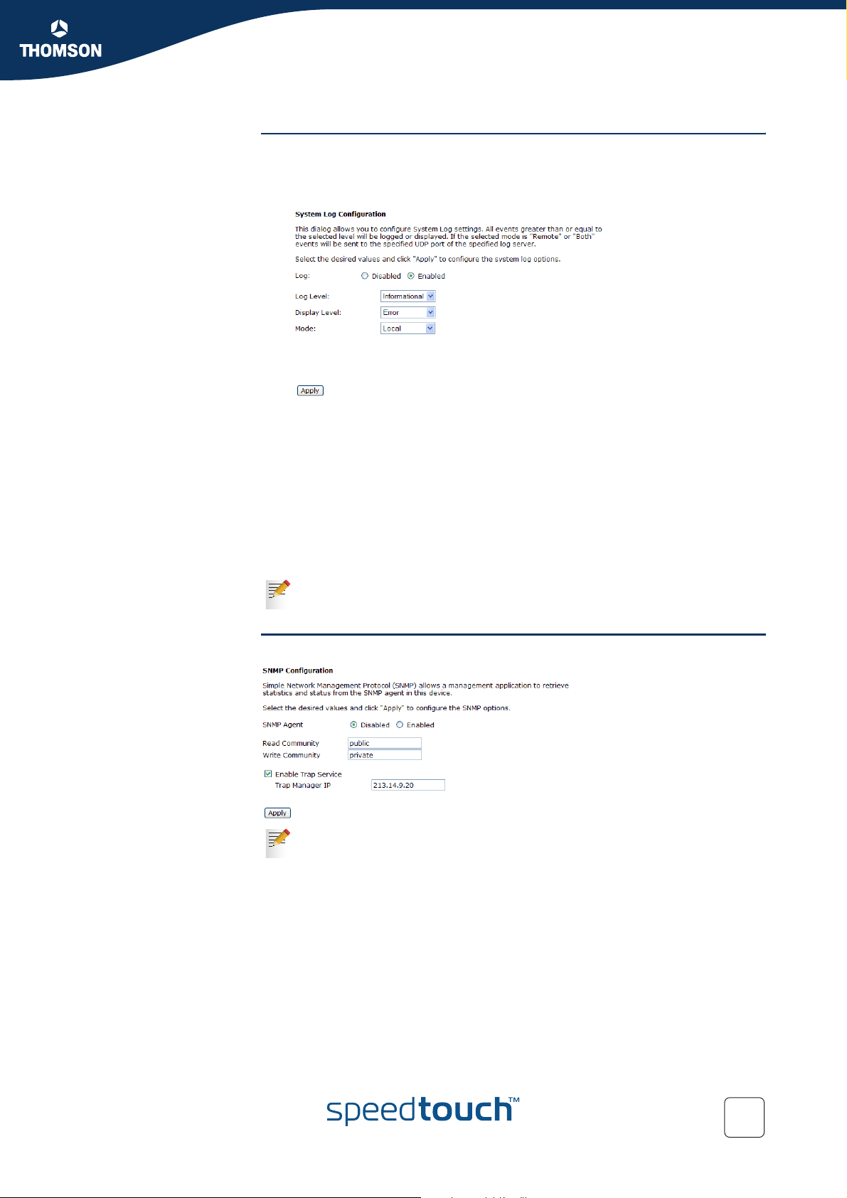
System Log The System Log page allows you to:
View the activity on the SpeedTouch™ since power on.
Change the System Log options:
Following fields are available:
Log Level:
Allows you to specify the activities that will be logged. All the items
above the selected item will be logged.
Display Level:
Allows you to specify which logs will be shown if you click View System
Log. All the items above the selected item will be displayed in the list.
Mode:
Allows you to send the log files to a dedicated server.
If your SpeedTouch™ is in its default configuration, the system log will be
disabled.
Chapter 5
SpeedTouch™ Web Interface
SNMP Setting This page allows you to configure the SNMP settings:
For more information, see “7.2 SNMP” on page 94.
E-DOC-CTC-20041126-0014 v3.0
75
Page 78
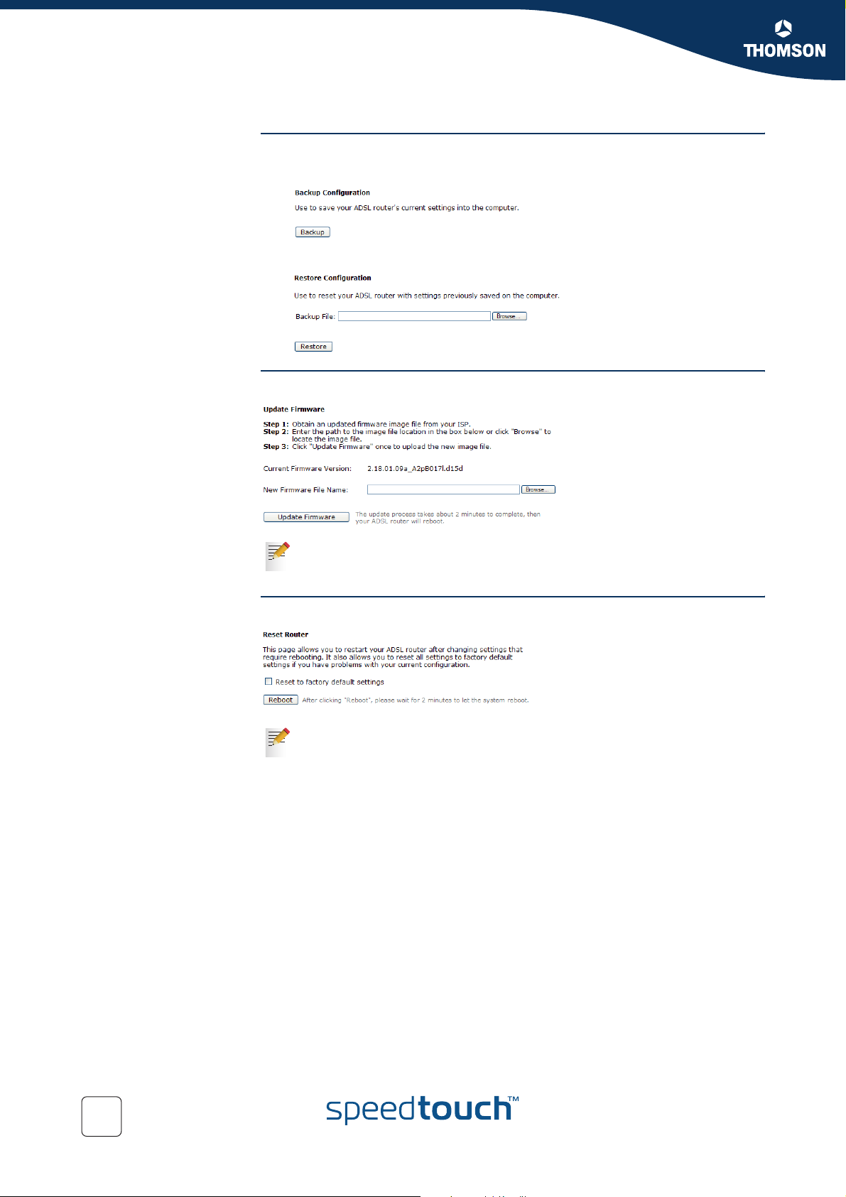
Chapter 5
SpeedTouch™ Web Interface
Backup Config The Backup Config page allows you to:
Update Firmware The Update Firmware page allows you to update your firmware:
Backup your current configuration:
Upload and apply a SpeedTouch™ backup configuration file.
For more information, see “8.1 Updating your Firmware” on page 98.
Reset Router The Reset Router page allows you to reboot/reset your SpeedTouch™:
For more information, see “8.3 Reset to Defaults” on page 102.
76
E-DOC-CTC-20041126-0014 v3.0
Page 79
6 Voice over IP
Traditional telephony For many years, most of the telephony was made on the old Public Switched
Telephone Network (PSTN) and, over time, telephone service providers have
enhanced their services by providing Custom Local Area Signalling Service
(CLASS) features to the customers. Those CLASS features permit subscribers of the
features to tailor their telephone service according to individual needs (e.g.: call
screening, call logging…).
New needs Rapidly, it appeared that a customised version of the CLASS features is required in
medium-to-large sized business, in order to facilitate business and group
communications. The so-called Private Branch eXchange (PBX) was born!
Voice over IP Today, Internet telephony, defined as the transport of telephone calls over the
Internet, can be used to send packets between two or more parties without
reserving the connection. Furthermore, based on a powerful signalling protocol
such as SIP protocol, Voice over IP (VoIP) communications allow other Internet
applications as Web, e-mail, chat, presence and instant messaging to be blended
with voice to provide entirely new classes of services and features not available
with circuit-switched telephony.
Chapter 6
Voice over IP
VoIP populari ty Despite Quality of Service (QoS) issues on the public Internet network and the quick
The SpeedTouch™ VoIP
solution
erosion of cost differentials between PSTN- based telephony and IP-based
telephony, Voice over IP communications are more and more popular.
Consequently, they are pushed by a number of the industry's leading providers,
including Microsoft®, AOL and Yahoo!
Using the SpeedTouch™ you can access VoIP networks using traditional phones.
Depending on the SpeedTouch™ variant you can make your VoIP phone call using:
Session Initiation Protocol
Media Gateway Control Protocol
E-DOC-CTC-20041126-0014 v3.0
77
Page 80
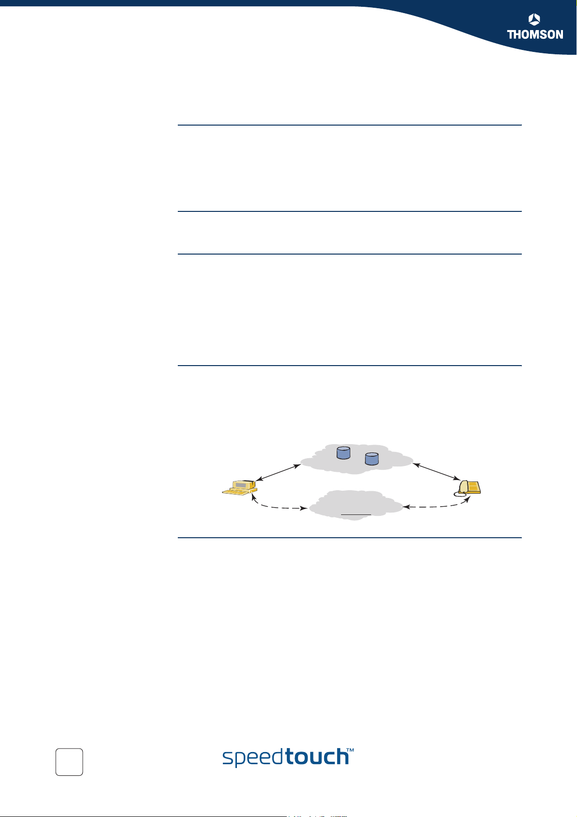
Chapter 6
j
Voice over IP
6.1 Session Initiation Protocol
Definition Session Initiation Protocol (SIP), defined in RFC 3261, is a signalling protocol used
for:
Initiating sessions in an IP network.
Modifying the sessions in an IP network.
Terminating sessions in an IP network.
Components A SIP-enabled IP network includes usual IP components and services such as
routers and DNS servers, as well as SIP User Agents (UA) and SIP network servers.
SIP User Agents The SIP User Agents, addressed by SIP URLs, are effectively the end system
components for a session (e.g. IP phone, PC or PDA); they originate and terminate
SIP requests.
SIP User Agents can implement advanced services such as:
Call Waiting
Call Hold
Call Transfer for IP telephony
SIP proxy server The SIP network servers are network devices that handle the signalling associated
with multiple sessions. In a proxy model, a SIP proxy server forwards signalling
messages between the called and calling parties; it is the only point of contact that
the clients have for signalling messages. After the session has been established, the
RTP audio or video packets are sent directly between the clients.
SIP UA1
ohn@rennes
SIP signalling
messages
RTP
Audio/Video
Registrars
(optional)
SIP-enabled IP network
IP network
SIP proxy servers
(optional)
SIP signalling
messages
RTP
Audio/Video
SIP UA2
julie@paris
SIP registrar A SIP proxy server makes use of a location database, updated by a SIP registrar, in
order to locate the called user agent. SIP UAs periodically register their current
location with a SIP registrar that may be collocated with a SIP proxy server.
78
E-DOC-CTC-20041126-0014 v3.0
Page 81
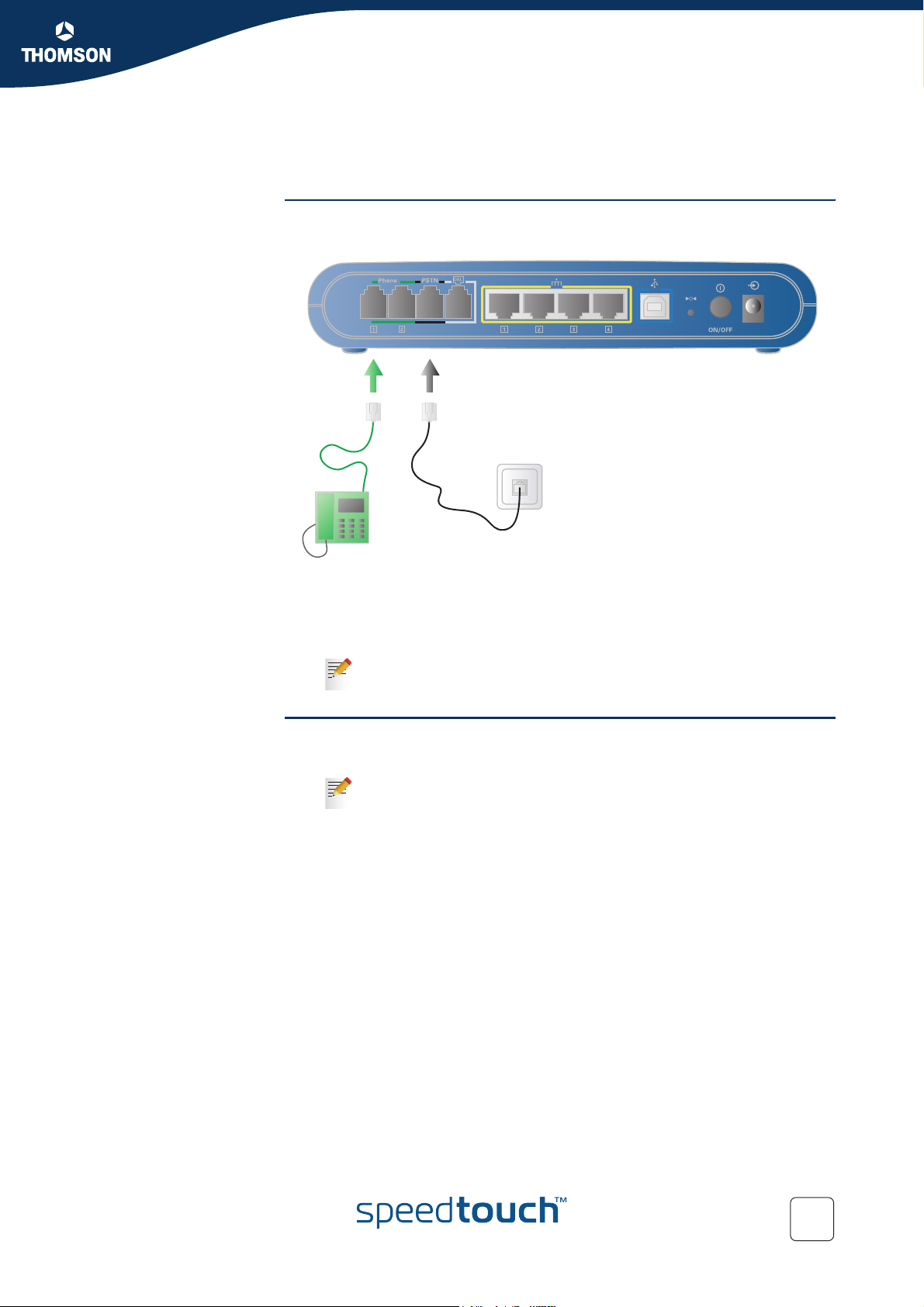
6.1.1 Configuration
Hardware installation
Chapter 6
Voice over IP
Use a phone cable to:
1 Wire the SpeedTouch™ Phone port(s) to your phone(s).
2 Wire the SpeedTouch™ PSTN port to your telephone wall outlet or distributed
filter depending on your Service Provider’s specific needs.
This step is only required if you still want to make phone calls using
the PSTN.
Basic SIP configuration Proceed as follows:
1 Open the SpeedTouch™ web pages.
For more information, see “5.1 Accessing the SpeedTouch™ Web
Pages” on page 44.
2 Browse to Voice > SIP Basic
3 The SIP Basic Settings page appears.
4 If the SIP proxy and registrar are located:
On your local network, click Primary LAN.
On the WAN, click the interface name of your WAN connection.
5 Under SIP Registrar Address, enter the IP address or domain name of your SIP
registrar server.
6 Under SIP Outbound Proxy, enter the IP address or domain name of your SIP
proxy server.
7 Under Registration Information, enter the registration information provided
by your SIP registrar.
8 Click Apply.
9 If you are:
Not using the PSTN port, no additional configuration is needed.
Using the PSTN port, continue with “ PSTN Configuration” on page 80.
E-DOC-CTC-20041126-0014 v3.0
79
Page 82

Chapter 6
Voice over IP
PSTN Configuration Proceed as follows:
1 On the left menu, click PSTN Control.
2 In the Select Tone/Ring Signals for list, click your region.
3 In the Prefix digits to dial PSTN phone call box, type the prefix you want to dial
to make phone calls using the PSTN.
4 Click Apply.
80
E-DOC-CTC-20041126-0014 v3.0
Page 83
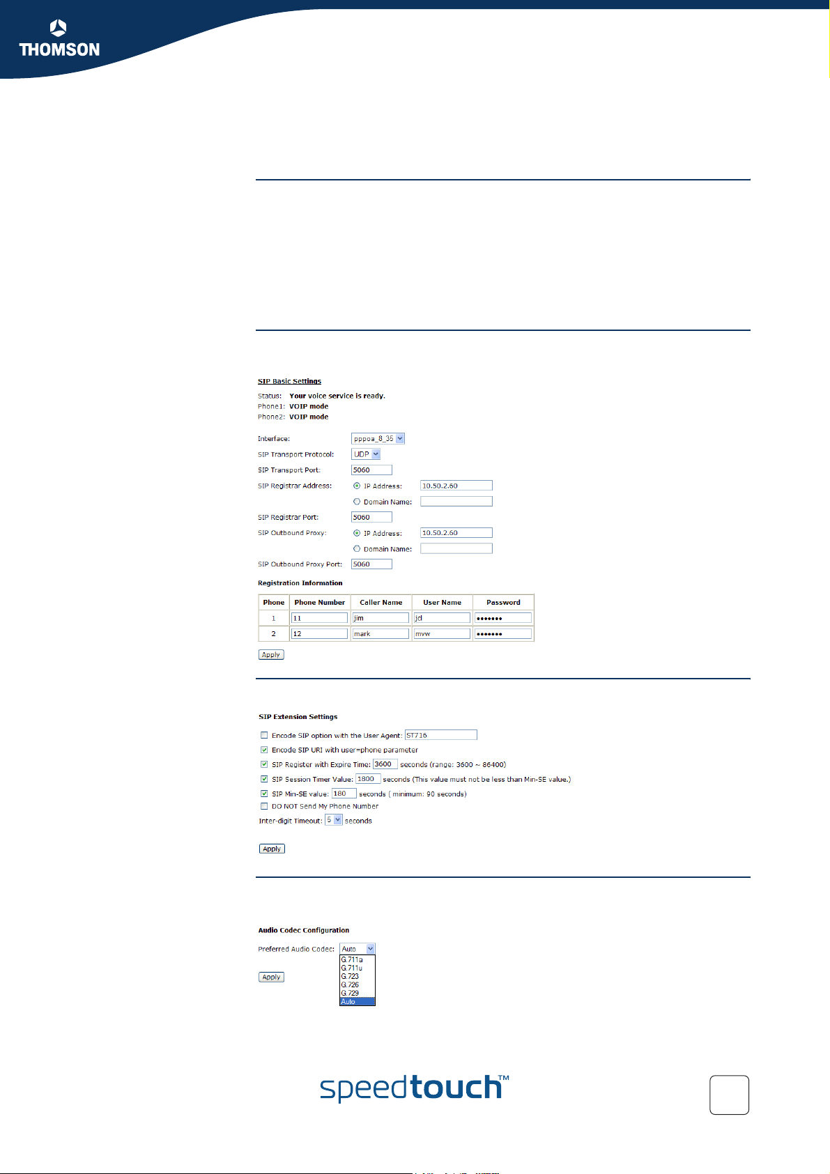
6.1.2 SIP Web Pages
The Voice menu Following items are available on the Voi ce menu:
SIP Basic
SIP Extension
Audio Codec
PSTN Control
Call Log
SIP Basic The SIP Basic Settings page allows you to configure your connection to the SIP
servers:
Chapter 6
Voice over IP
SIP Extension The SIP Extension page allows you to configure advanced SIP settings:
Audio Codec The Audio Codec Configuration page allows you to select the audio codec of your
E-DOC-CTC-20041126-0014 v3.0
choice:
81
Page 84
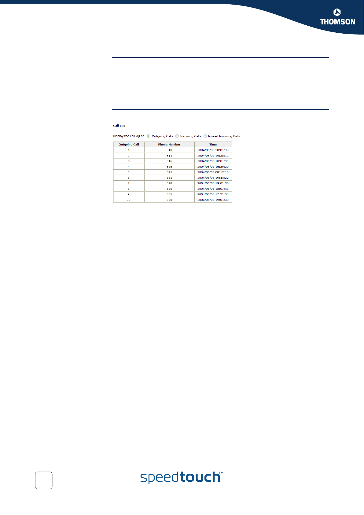
Chapter 6
Voice over IP
PSTN Control The PSTN Control page allows you to configure:
The tone ring signals specific to your country.
The prefix digits for PSTN calls.
If you dial this prefix (default “*”), the SpeedTouch™ will use the PSTN
network to call the number following the prefix.
Call Log The SpeedTouch™ logs all VoIP activity on the Call Log page:
82
E-DOC-CTC-20041126-0014 v3.0
Page 85

6.2 Media Gateway Control Protocol
Definition Media Gateway Control Protocol (MGCP) is a standard protocol for handling the
signalling and session management needed during a multimedia conference.
MGCP can be used to:
Set up
Maintain
Te rm in at e
calls between multiple endpoints.
Components The Media Gateway Control Protocol (MGCP) is an IETF defined protocol for
controlling Media Gateways (MGs) from external call elements called Media
Gateway Controllers (MGCs) or Call Agents.
Chapter 6
Voice over IP
E-DOC-CTC-20041126-0014 v3.0
83
Page 86
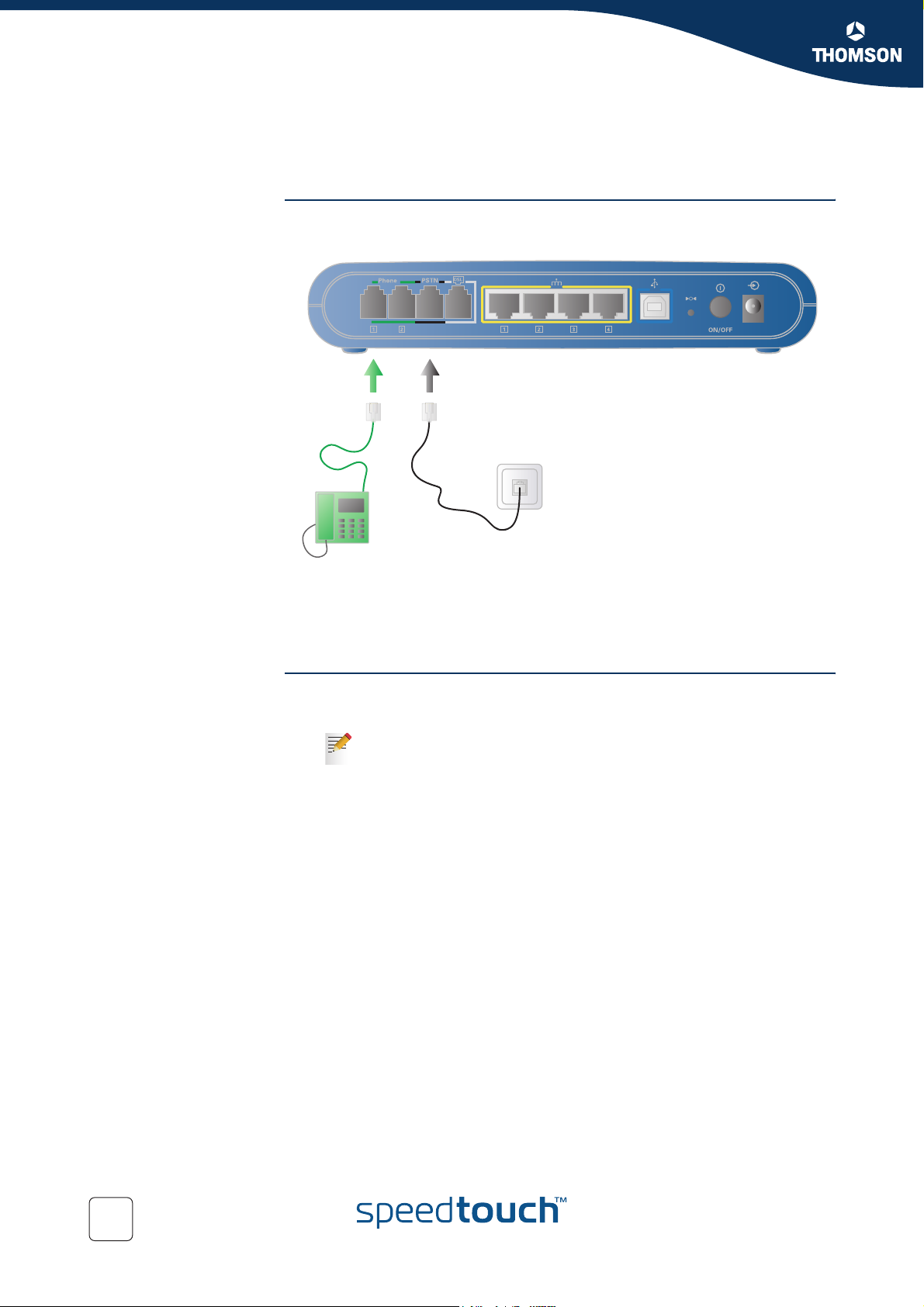
Chapter 6
Voice over IP
6.2.1 Configuration
Hardware installation
Basic MGCP
configuration
Use a phone cable to:
1 Wire the SpeedTouch™ Phone port(s) to your phone(s).
2 Wire the SpeedTouch™ PSTN port to your telephone wall outlet or distributed
filter depending on your Service Provider’s specific needs.
Proceed as follows:
1 Open the SpeedTouch™ web pages:
For more information, see “5.1 Accessing the SpeedTouch™ Web
Pages” on page 44.
2 Browse to Voice > MGCP.
3 The MGCP configuration page appears.
4 If the Call Agent is located:
On your local network, click LAN.
On the WAN, click the interface name of your WAN connection.
5 Enter the Device Name and Call Agent IP Address.
6 Click Apply.
7 If you are:
Not using the PSTN port, no additional configuration is needed.
Using the PSTN port, continue with “ PSTN Configuration” on page 85.
84
E-DOC-CTC-20041126-0014 v3.0
Page 87

PSTN Configuration Proceed as follows:
1 On the left menu, click PSTN Control.
2 In the Select Tone/Ring Signals for list, click your region.
3 In the Prefix digits to dial PSTN phone call box, type the prefix you want to dial
to make phone calls using the PSTN.
4 Click Apply.
Chapter 6
Voice over IP
E-DOC-CTC-20041126-0014 v3.0
85
Page 88
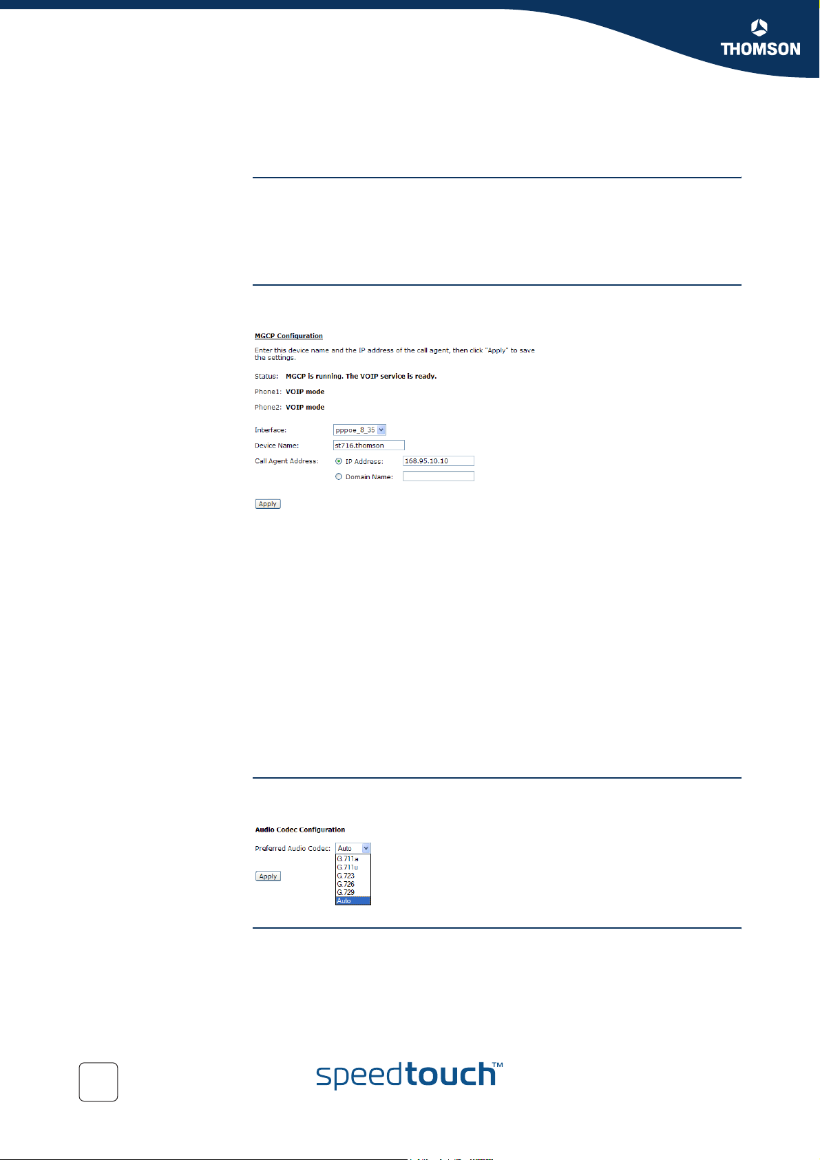
Chapter 6
Voice over IP
6.2.2 MGCP Web Pages
The VoIP menu Following items are available on the VoI P menu:
MGCP
Audio Codec
PSTN Control
MGCP The MGCP Configuration page allows you to configure your connection to the call
agent:
Following fields are available for configuration:
Status:
Indicates the current status of your VoIP network. Depending on the current
status one of the following messages will be shown:
MGCP is running. The VOIP service is ready.
Call agent is down. You cannot make VOIP phone calls.
Internet connection is not available. You cannot make VOIP phone calls.
Interface:
The interface you want to use to connect to your call agent.
Device Name:
The device name you registered at the ISP for your router.
Call Agent IP Address:
The IP address of your call agent.
Audio Codec The Audio Codec Configuration page allows you to select the audio codec of your
choice:
86
PSTN Control This page allows you to configure:
The tone/ring signals specific to your country.
The prefix digits for PSTN calls.
If you dial this prefix (default “*”), the SpeedTouch™ will use the PSTN
network to call the number following the prefix.
E-DOC-CTC-20041126-0014 v3.0
Page 89

6.3 VoIP Call Features
Introduction The SpeedTouch™ offers you following VoIP call features:
Call Transferring
Call Waiting
3-ways Conference Calls
Chapter 6
Voice over IP
E-DOC-CTC-20041126-0014 v3.0
87
Page 90

Chapter 6
Voice over IP
6.3.1 Call Transferring
Example You receive a phone call from person A and you want to transfer him to person B.
Procedure Proceed as follows:
1 If your phone has:
A hook flash button, press it.
For more information, consult your phone’s user documentation
No hook flash button, put down the hook for 1/2 second
to put person A on hold.
2 Wait for the dial tone.
3 Dial the number of person B.
4 Person B picks up the phone.
5 Hang up the phone to transfer the call.
88
E-DOC-CTC-20041126-0014 v3.0
Page 91
6.3.2 Call Waiting
Example You are in a phone conversation with person A while person B is calling you. The
phone produces a waiting tone and displays the name or number of person B on
the display.
Chapter 6
Voice over IP
Switching to the new
caller
Proceed as follows
1 If your phone has:
A hook flash button, press it.
For more information, consult your phone’s user documentation
No hook flash button, put down the hook for 1/2 second.
2 Person A is put on hold while you talk to person B.
3 At the end of the conversation with person B you are redirected to person A.
E-DOC-CTC-20041126-0014 v3.0
89
Page 92
Chapter 6
Voice over IP
6.3.3 3-ways Conference Calls
Example You want to make a conference call with person A and person B.
Procedure Proceed as follows:
1 Call person A.
2 If your phone has:
A hook flash button, press it.
For more information, consult your phone’s user documentation.
No hook flash button, put down the hook for 1/2 second.
3 Person A is put on hold.
4 Wait for the dial tone.
5 Dial the number of person B.
6 Person B picks up the phone.
7 Dial hook flash to start the 3-way conference.
90
E-DOC-CTC-20041126-0014 v3.0
Page 93

Chapter 7
Advanced Configuration
7 Advanced Configuration
Introduction This chapter will guide you through some advanced features of the SpeedTouch™.
Contents Following topics are described:
Setting up a Virtual Server
SNMP
E-DOC-CTC-20041126-0014 v3.0
91
Page 94
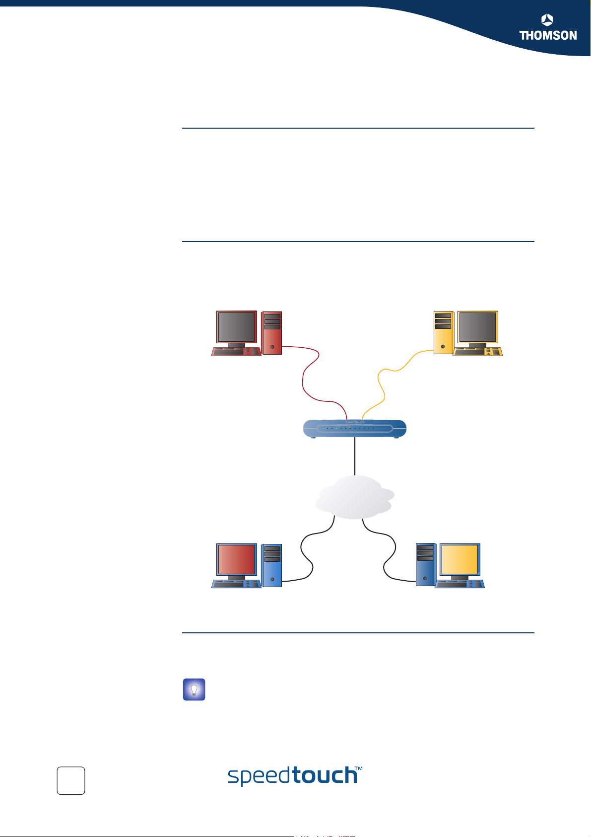
Chapter 7
Advanced Configuration
Example configuration In the example below, both Internet users are connecting to the same IP address,
7.1 Setting up a Virtual Server
Introduction Using Network Address Translation (NAT), the SpeedTouch™ is able to make your
local network act as a single machine to the Internet. This enables you to divide the
services of your server over different host computers.
When the SpeedTouch™ receives an incoming IP packet requesting access to your
local server, the SpeedTouch™ will recognise the service type according to the port
number in this packet (for example, port 80 indicates HTTP service and port 21
indicates FTP service). By specifying the port number, the SpeedTouch™ is able to
forward this service to the correct local IP.
but using different protocols. To access:
The virtual web server they have to enter http://203.70.212.52.
The virtual FTP server they have to enter ftp://203.70.212.52.
Web Server
IP address: 192.168.1.10
http://203.70.212.52
Remote PC using web server
DSL PPP WLANEthernet
1432
VoIPReady
PhoneUSBPWR
WAN IP address: 203.70.212.52
Internet
Remote PC using FTP Server
FTP Server
IP address: 192.168.1.20
ftp://203.70.212.52
WAN IP address To Internet users, all your virtual servers have the same IP Address. This IP Address
is allocated by your ISP. This address should be static, rather than dynamic, to make
it easier for Internet users to connect to your Servers.
You can also use Dynamic DNS feature to allow users to connect to your
virtual servers by using a URL, instead of an IP address.
92
E-DOC-CTC-20041126-0014 v3.0
Page 95
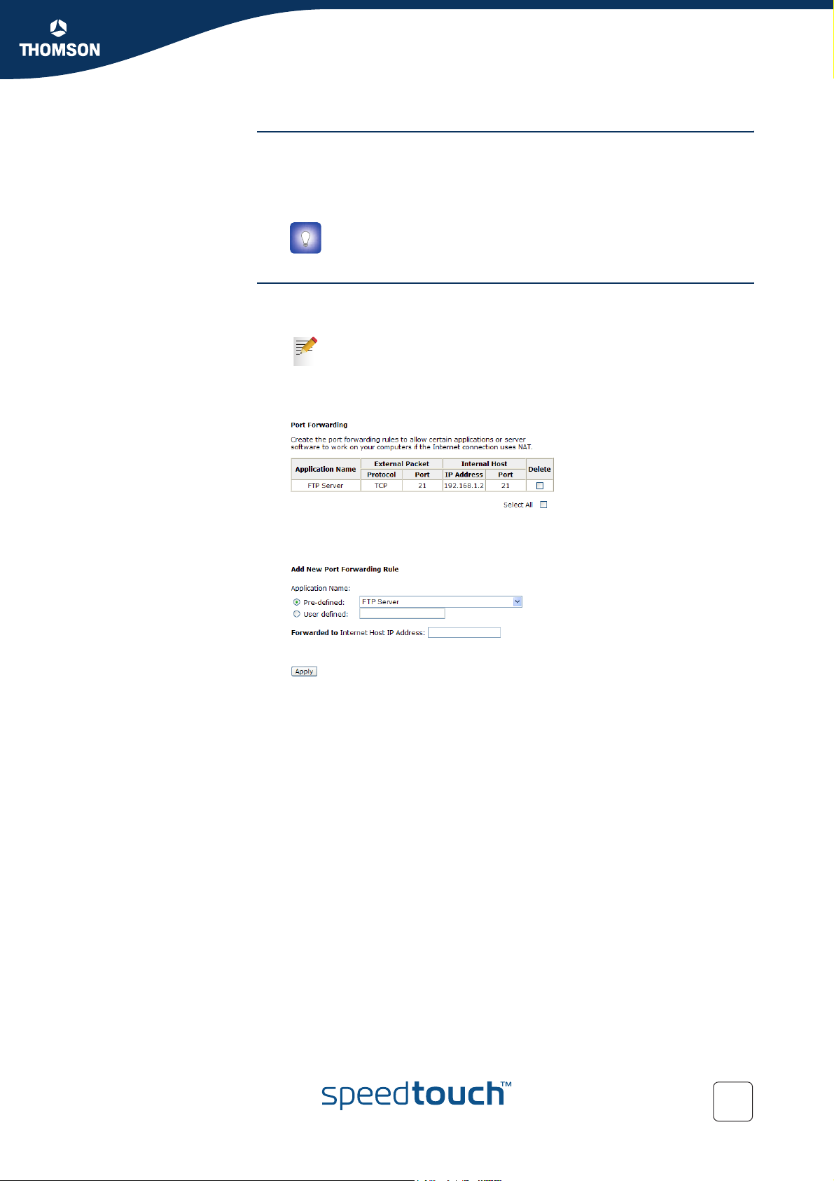
Chapter 7
Advanced Configuration
Host computer
configuration
SpeedTouch™
configuration
Make sure that:
The firewall on the host computer (for example Windows Firewall) allows the
service to be accessed on this computer.
The host computer is configured with a static IP address.
You can also reserve an IP address for this computer. For more
information on the SpeedTouch™, see “ The DHCP Server page” on
page 57.
Proceed as follows:
1 Open the SpeedTouch™ web pages.
For more information, see “5.1 Accessing the SpeedTouch™ Web
Pages” on page 44.
2 Browse to Advanced > Virtual Server > Port Fowarding
3 The Port Forwarding page appears:
Click Add to add the new port forwarding rule.
4 The Add New Port Forwarding Rule appears:
E-DOC-CTC-20041126-0014 v3.0
5 If you want to:
Create a port forwarding entry for a specific application:
1 Select an application in the Pre-defined list.
2 Type the IP address of the local host that will be used to provide this
service in the Forwarded to field.
3 Click Apply.
Manually create a port forwarding entry.
1 Enter a name for the application.
2 Type the IP address of the local host that will be used to provide this
service in the Forwarded to field.
3 Enter the port forwarding rules in the By using the rules table.
4 Click Apply.
6 The SpeedTouch™ adds the new rule to the Port Forwarding table.
93
Page 96
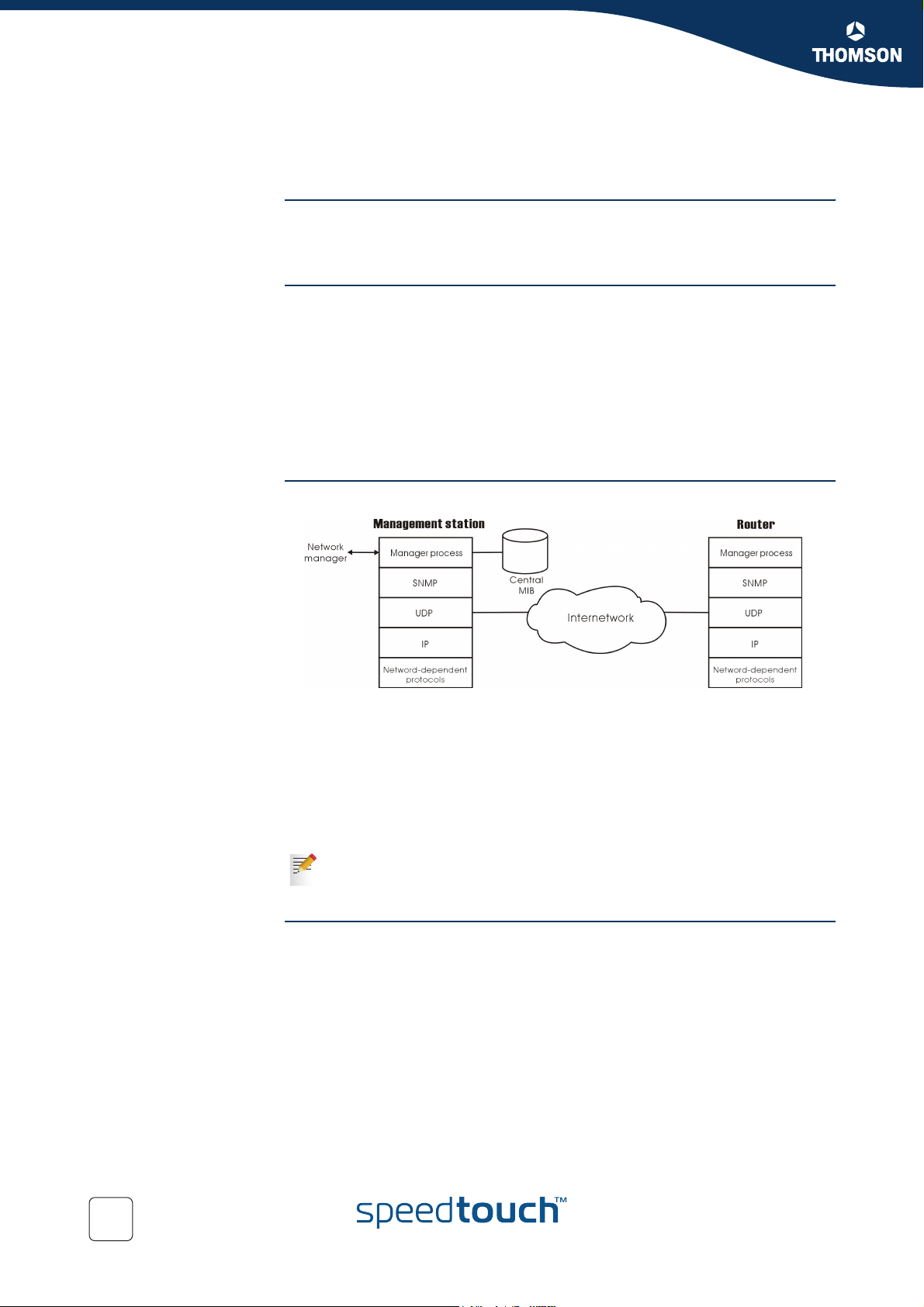
Chapter 7
Advanced Configuration
7.2 SNMP
Function The Simple Network Management Protocol (SNMP) is used to refer to a collection
of specifications for network management that include the protocol itself, the
definition of data structures and associated concepts.
SNMP A management station performs the monitoring function by retrieving the value of
MIB objects. The management station and agents are linked by a network
management protocol called SNMP. The SNMP includes three key capabilities
Get
Set
Tra p
A single management station can handle many agents as long as SNMP remains
relatively “simple”, so the number can be high (hundreds or so).
Example The following picture is the typical configuration of protocols for SNMP.
As for a stand-alone management station, a manager process controls access to a
central MIB at the management station and provides an interface to the network
manager. The manager process achieves network management by using SNMP,
which will be implemented on top of the UDP, IP and the relevant networkdependent protocols (for example, Ethernet).
For an agent device that supports other applications, such as FTP, both TCP and
UDP are required. An agent may issue a trap message in response to an event that
effects the MIB and the underlying managed resources.
There are no ongoing connections maintained between a management
station and its agents. Instead, each exchange is a separate transaction
between a management station and an agent.
Traps Each agent is responsible for notifying the management station of any unusual
event. For example:
If the agent crashes and is rebooted
A link fails
An overload condition as defined by the packet load crosses some threshold
...
These events are communicated in SNMP messages known as traps.
94
E-DOC-CTC-20041126-0014 v3.0
Page 97
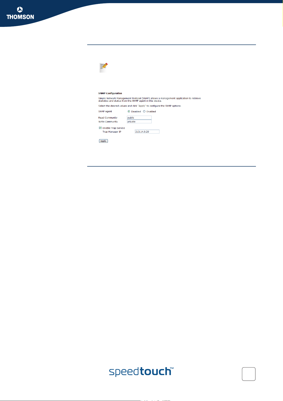
Chapter 7
Advanced Configuration
Configuring SNMP on
the SpeedTouch™
Proceed as follows:
1 Open the SpeedTouch™ web pages.
For more information, see “5.1 Accessing the SpeedTouch™ Web
Pages” on page 44.
2 Browse to Management > SNMP.
3 The SNMP Configuration page appears:
Enter your settings.
4 Click Apply.
E-DOC-CTC-20041126-0014 v3.0
95
Page 98

Chapter 7
Advanced Configuration
96
E-DOC-CTC-20041126-0014 v3.0
Page 99

8 Support
In this chapter This chapter contains following topics:
Updating your Firmware
UPnP™ on Windows XP Systems
Reset to Defaults
Troubleshooting
Chapter 8
Support
E-DOC-CTC-20041126-0014 v3.0
97
Page 100
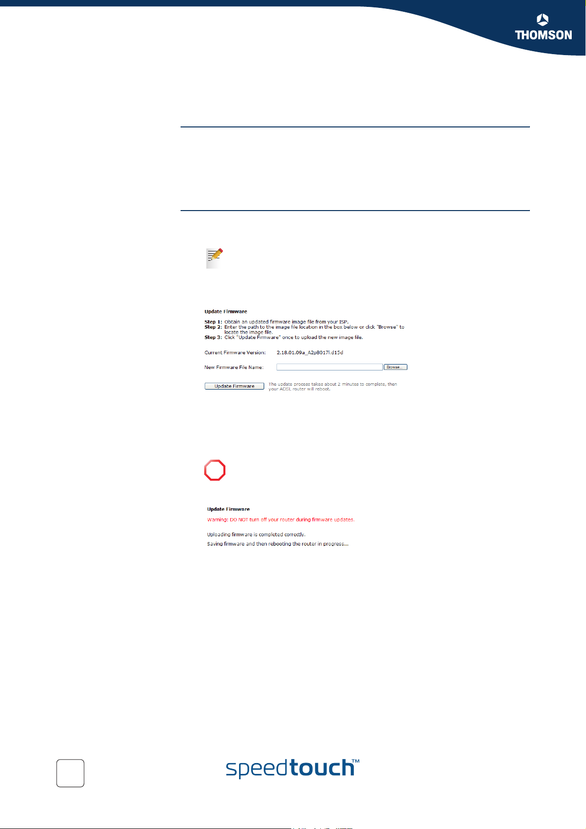
Chapter 8
Support
8.1 Updating your Firmware
Before you start Make sure:
To inform all people relying on the SpeedTouch™ services, that the service
may be down for some short period
That the new system software file is stored on your local disk or another
storage device.
Procedure Proceed as follows:
1 Open the SpeedTouch™ web pages.
For more information, see “5.1 Accessing the SpeedTouch™ Web
Pages” on page 44.
2 Browse to Management > Update Firmware.
3 The Update Firmware page appears:
Click Browse.
4 Locate the firmware upgrade file on your computer and click Open.
5 Click Update Firmware.
6 The SpeedTouch™ uploads the new firmware.
Do not turn off your SpeedTouch™ during the update procedure.
!
7 The SpeedTouch™ saves the new firmware and restarts:
98
E-DOC-CTC-20041126-0014 v3.0
 Loading...