

Alcatel-Lucent OmniSwitch OS6450-24, OmniSwitch OS6450-P24, OmniSwitch OS6450-24L, OmniSwitch OS6450-10L, OmniSwitch OS6450-P24L Hardware User's Manual
...
Part No. 060351-10, Rev. G
September 2015
OmniSwitch 6450
Hardware Users Guide
enterprise.alcatel-lucent.com

This user guide documents the OmniSwitch 6450 for AOS Release 6.7.1.
This user guide documents OmniSwitch 6450 hardware, including chassis and associated components.
The specifications described in this guide are subject to change without notice.
enterprise.alcatel-lucent.com Alcatel-Lucent and the Alcatel-Lucent Enterprise logo are trademarks of
Alcatel-Lucent. To view other trademarks used by affiliated companies of ALE Holding, visit:
enterprise.alcatel-lucent.com/trademarks. All other trademarks are the property of their respective owners.
The information presented is subject to change without notice. Neither ALE Holding nor any of its affiliates
assumes any responsibility for inaccuracies contained herein. (July 2015)
26801 West Agoura Road
Calabasas, CA 91301
(818) 880-3500 FAX (818) 880-3505
EMEA: +800 00200100 (Toll Free) or +1(650)385-2193
Service & Support Contact Information
North America: 800-995-2696
Latin America: 877-919-9526
Asia Pacific: +65 6240 8484
Web: service.esd.alcatel-lucent.com
Email: esd.support@alcatel-lucent.com

Contents
About This Guide ..............................................................................................................xi
Supported Platforms ..........................................................................................................xi
Who Should Read this Manual? .......................................................................................xii
When Should I Read this Manual? ...................................................................................xii
What is in this Manual? ....................................................................................................xii
What is Not in this Manual? .............................................................................................xii
How is the Information Organized? ................................................................................xiii
Documentation Roadmap ......................................................................................... .... ...xiii
Related Documentation ....................................................................................................xv
Published / Latest Product Documentation .....................................................................xvi
Technical Support ...........................................................................................................xvi
Documentation Feedback ................................................................................................xvi
Chapter 1 OmniSwitch 6450 Switches .............................................................................................1-1
Chassis Configurations ....................................................................................................1-2
10-Port Models .........................................................................................................1-2
24-Port Models .........................................................................................................1-2
48-Port Models .........................................................................................................1-3
Combo Ports ......................................................................................................1-3
Non-combo Fiber Ports .....................................................................................1-3
OmniSwitch 6450 Feature Overview ..............................................................................1-4
Power over HD Base-T (PoH) Support ....................................................................1-4
IEEE 1588 Precision Time Protocol (PTP) Support ................................................1-4
Security Features ......................................................................................................1-4
Availability Features ................................................................................................1-5
Software Rollback .......................................................................................... ...1-5
Hot Swapping ....................................................................................................1-5
Hardware Monitoring ..................................................................... .... ...............1-6
Chapter 2 Getting Started ...............................................................................................................1-1
Installing the Hardware ...................................................................................................1-1
Items Required .......................................................................... .... ...........................1-1
Site Preparation ........................................................................................................1-1
Environmental Requirements ............................................................................1-1
Electrical Requirements .....................................................................................1-1
Unpacking and Installing the Switch .......................................................................1-2
Items Included ........................................................................................ .... .......1-2
Weight Considerations ......................................................................................1-2
Airflow Considerations .....................................................................................1-3
OmniSwitch 6450 Hardware Users Guide September 2015 iii

Contents
Mounting the Switch .......................................................................................................1-3
Connections and Cabling ................................................................................................1-4
Serial Connection to the Console Port ...............................................................1-4
Serial Connection Default Settings ...................................................................1-4
Booting the Switch ..........................................................................................................1-5
Component LEDs ..............................................................................................1-5
Your First Login Session ................................................................................................1-6
Logging In to the Switch ..........................................................................................1-6
Unlocking Session Types .............................................................. .... .... ...................1-7
Changing the Login Password ..................................................................................1-8
Setting the System Time Zone .................................................................................1-8
Setting the Date and Time ........................................................................................1-8
Setting Optional Parameters ................... ..................................................................1-9
Specifying an Administrative Contact ........................................ .... .... .... ...........1-9
Specifying a System Name ................................................................................1-9
Specifying the Switch’s Location ......................................................................1-9
Viewing Your Changes ............................................................................................1-9
Saving Your Changes ...............................................................................................1-9
Chapter 3 OmniSwitch 6450 Chassis and Hardware Components ................................................2-1
OmniSwitch 6450-10 ......................................................................................................2-2
Chassis Features ................................................................................ .... .... ...............2-2
Front Panel ...............................................................................................................2-2
OmniSwitch 6450-10 Rear Panel .............................................................................2-3
OmniSwitch 6450-10 Internal AC Power Supply ....................................................2-3
OmniSwitch 6450-P10 ....................................................................................................2-5
Chassis Features ................................................................................ .... .... ...............2-5
Front Panel ...............................................................................................................2-5
OmniSwitch 6450-P10 Rear Panel ...........................................................................2-6
OmniSwitch 6450-P10 Internal AC Power Supply ..................................................2-6
OmniSwitch 6450-P10S ..................................................................................................2-8
Front Panel ...............................................................................................................2-8
OmniSwitch 6450-P10S Rear Panel ......................................................................2-10
OmniSwitch 6450-P10S Internal AC Power Supply .............................................2-11
OmniSwitch 6450-24 ....................................................................................................2-13
Chassis Features ................................................................................ .... .... .............2-13
Front Panel .............................................................................................................2-13
OmniSwitch 6450-24 Rear Panel ...........................................................................2-14
OmniSwitch 6450-24 Internal AC Power Supply ..................................................2-14
OmniSwitch 6450-P24 ..................................................................................................2-16
Chassis Features ................................................................................ .... .... .............2-16
Front Panel .............................................................................................................2-16
OmniSwitch 6450-P24 Rear Panel .........................................................................2-17
OmniSwitch 6450-P24 Internal AC Power Supply ................................................2-17
iv OmniSwitch 6450 Hardware Users Guide September 2015

Contents
OmniSwitch 6450-48 ....................................................................................................2-19
Chassis Features ................................................................................ .... .... .............2-19
Front Panel .............................................................................................................2-19
OmniSwitch 6450-48 Rear Panel ...........................................................................2-20
OmniSwitch 6450-48 Internal AC Power Supply ..................................................2-20
OmniSwitch 6450-P48 ..................................................................................................2-22
Chassis Features ................................................................................ .... .... .............2-22
Front Panel .............................................................................................................2-22
OmniSwitch 6450-P48 Rear Panel .........................................................................2-23
OmniSwitch 6450-P48 Internal AC Power Supply ................................................2-23
OmniSwitch 6450-U24 .................................................................................................2-25
Chassis Features ................................................................................ .... .... .............2-25
Front Panel .............................................................................................................2-25
OmniSwitch 6450-U24 Rear Panel ........................................................................2-26
OmniSwitch 6450-U24 Internal AC Power Supply ...............................................2-26
OmniSwitch 6450-U24S ...............................................................................................2-28
Front Panel .............................................................................................................2-28
OmniSwitch 6450-U24S Rear Panel ......................................................................2-30
OmniSwitch 6450-U24S Internal AC Power Supply .............................................2-30
OmniSwitch 6450 LED Status ......................................................................................2-32
Expansion Modules ................................... ....................................................................2-33
OS6450-GNI-C2 ....................................................................................................2-33
OS6450-GNI-U2 .................................................................................................... 2-33
OS6450-XNI-U2 .................................................................................................... 2-34
OmniSwitch 6450 Internal Backup Power Supplies .....................................................2-35
PS-90W-AC 90W AC Power Supply .....................................................................2-35
PS-90W-DC 90W DC Power Supply .....................................................................2-35
OmniSwitch 6450 External Backup Power Supplies ....................................................2-36
PS-550W-AC-P External 550W AC PoE Power Supply .......................................2-36
PS-900AC-P External 900W AC PoE Power Supply ............................................2-36
Installing Expansion Modules .......................................................................................2-37
Removing Expansion Modules .....................................................................................2-39
Installing Power Supplies ..............................................................................................2-41
Removing Power Supplies .....................................................................................2-43
AC Power Cords ...........................................................................................................2-45
Specifications .........................................................................................................2-45
Console Port ..................................................................................................................2-46
Serial Connection Default Settings ........................................................................2-46
Port Pinouts .................................................................................. .................................2-47
RJ-45 Console Port – Connector Pinout ................................................................2-47
10/100 Ethernet Port – RJ-45 Pinout (non-PoE) .................................................... 2-47
Gigabit Ethernet Port – RJ-45 Pinout .....................................................................2-47
10/100/1000 Mbps Power over Ethernet Port – RJ-45 Pinout ..............................2-48
Overtemp Condition ................... ... .... ....................................................... .... .................2-48
OmniSwitch 6450 Hardware Users Guide September 2015 v

Contents
Dying Gasp ....................................................................................................................2-49
Scenarios ................................................................................................................2-49
SNMP Trap ......................................................................................................2-49
Syslog Message ...............................................................................................2-49
Link OAM PDU ..............................................................................................2-50
Chapter 4 Mounting OmniSwitch 6450 Switches ............................................................................ 3-1
General Installation Recommendations ..........................................................................3-2
Airflow Recommendations ......................................................................................3-2
Mechanical Loading .................................................................................................3-4
Circuit Overloading ..................................................................................................3-4
Reliable Earthing ......................................................................................................3-4
Table-Mounting OS6450 Switches .................................................................................3-4
General Table-Mounting Guidelines ........................................................................ 3-4
Table-Mounting Installation .....................................................................................3-4
Rack-Mounting 10-Port OS6450 Switches .....................................................................3-5
Available 10-Port Rack-Mounting Kits ...................................................................3-5
General Rack-Mounting Guidelines .............................................................. ...........3-5
Installing Available Rack Mounting Kits .......................................................................3-6
Installing the OS6450-RM-19-L Rack Mount Kit ...................................................3-6
Installing the OS6450-DUAL-MNT Rack Mount Kit .............................................3-7
Rack-Mounting 24 and 48-Port OS6450 Switches .......................................................3-10
Rack Mounting Steps .............................................................................................3-11
Installing External PoE Power Supplies .......................................................................3-13
Rack Mounting Power Supplies .............................................................................3-13
Connecting the Power Supply Cable ...............................................................3-14
DC Power Supply Considerations ..........................................................................3-15
Connecting Chassis to Power Source ............................................................................3-15
AC Power Supply Connections ..............................................................................3-15
Powering On a Chassis .................................... .... ............................................3-15
Chapter 5 Booting OmniSwitch 6450 Switches ...............................................................................4-1
Booting an OmniSwitch ...........................................................................................4-1
Console Port ....................................................................................................................4-2
Serial Connection Default Settings ..........................................................................4-2
Modifying the Serial Connection Settings ...............................................................4-2
Monitoring the Chassis ...................................................................................................4-4
Checking the Overall Chassis Status ........................................................................4-4
Checking the Temperature Status ............................................................................4-4
Viewing the Power Supply Status ............................................................................ 4-5
Additional Monitoring Commands ..........................................................................4-5
Using LEDs to Visually Monitor the Chassis ..........................................................4-5
vi OmniSwitch 6450 Hardware Users Guide September 2015

Contents
Chapter 6 Managing Power over Ethernet (PoE) ...........................................................................5-1
In This Chapter ................................................................................. .... .... .... ...................5-2
Power over Ethernet Specifications ................................................................................5-3
Viewing PoE Power Supply Status .................................................................................5-4
Configuring Power over Ethernet Parameters .................................................................5-4
Power over Ethernet Defaults ..................................................................................5-4
Understanding and Modifying the Default Settings .................................................5-4
PoE Class Detection ....................................................... ... .......................................5-5
Setting the PoE Operational Status ....................................................................5-5
Configuring the Total Power Available to a Port ............................... ...............5-6
Configuring the Total Power Available to a Switch .........................................5-6
Setting Port Priority Levels ...............................................................................5-7
Understanding Priority Disconnect .................................................................................5-8
Setting Priority Disconnect Status ............................................................................5-8
Disabling Priority Disconnect ...........................................................................5-8
Enabling Priority Disconnect ............................................................................5-8
Monitoring Power over Ethernet via CLI .....................................................................5-10
Chapter 7 Managing OmniSwitch 6450 Stacks ............................................................................... 6-1
In This Chapter ................................................................................. .... .... .... ...................6-1
OmniSwitch 6450 Stacking Specifications ..............................................................6-2
OmniSwitch 6450 Stack Overview .................................................................................6-2
Expansion Modules and Stacking Mode .........................................................................6-3
Swapping Expansion Modules .................................................................................6-3
OmniSwitch 6450-10 Mode .....................................................................................6-3
Roles Within the Stack ....................................................................................................6-4
Primary and Secondary Management Modules .......................................................6-4
Primary Management Module Selection ...........................................................6-7
Secondary Management Module Selection ..................................................... 6-10
Idle Module Role ....................................................................................................6-12
Pass-Through Mode ...............................................................................................6-13
Recovering from Pass-Through Mode (Duplicate Slot Numbers) ..................6-14
Stack Cabling ............................................ .... .... ............................................................6-17
Redundant Stacking Cable Connection ..................................................................6-18
Checking Redundant Stacking Cable Status ..........................................................6-19
Slot Numbering .............................................................................................................6-20
Dynamic Slot Number Assignment ........................................................................6-21
Manual Slot Number Assignment ..........................................................................6-23
Reverting to the Dynamic Slot Numbering Model ..........................................6-24
Hot-Swapping Modules In a Stack ...............................................................................6-25
Removing Switches from an Existing Stack ..........................................................6-25
Inserting Switches Into an Existing Stack ..............................................................6-25
Merging Stacks .......................................................................................................6-26
OmniSwitch 6450 Hardware Users Guide September 2015 vii

Contents
Reloading Switches .......................................................................................................6-27
Reloading the Primary Management Module ........................................................6-27
Reloading the Secondary Management Module ....................................................6-29
Reloading Switches with Idle Roles .......................................................................6-31
Reloading Switches in Pass-Through Mode ..........................................................6-31
Reloading All Switches in a Stack .........................................................................6-32
Software Synchronization During a Full Reload .............................................6-32
Effects of Saved Slot Number Information on the Reload Process .................6-32
Avoiding Split Stacks .............................................................................................6-34
Changing the Secondary Module to Primary ................................................................6-35
Synchronizing Switches in a Stack ...............................................................................6-37
Automatic Synchronization During a Full Reload .................................................6-37
Stack Split Detection (SSP) ..........................................................................................6-38
Stack Split Key Components and Terms ................................................................6-38
Basic Operation .............................................................. ... .... .................................6-39
Protection States .....................................................................................................6-39
Stack Split Recovery .......................................................................................6-39
Monitoring the Stack .....................................................................................................6-41
Visually Monitoring the Stack ...............................................................................6-41
Appendix A Regulatory Compliance and Safety Information ............................................... .............A-1
Declaration of Conformity: CE Mark .............................................................. .... .... .... ..A-1
China RoHS: Hazardous Substance Table .....................................................................A-2
California Proposition 65 Warning ................................................................................A-3
Waste Electrical and Electronic Equipment (WEEE) Statement ...................................A-4
Standards Compliance ....................................................................................................A-5
Safety Standards ......................................................................................................A-5
EMC Standards .......................................................................................................A-5
Environmental Standards ........................................................................................A-5
FCC Class A, Part 15 ..............................................................................................A-6
Canada Class A Statement ............................................................ ..........................A-6
JATE ........................................................................................................................A-6
CISPR22 Class A Warning .....................................................................................A-6
Korea Emissions Statement .....................................................................................A-7
Class A Warning for Taiwan and Other Chinese Markets ......................................A-7
Network Cable Installation Warning .............................................................................A-8
Translated Safety Warnings ...........................................................................................A-8
Chassis Lifting Warning ........................................................................ .... ..............A-8
Electrical Storm Warning ........................................................................................ A-8
Installation Warning ................................................................................................ A-8
Invisible Laser Radiation Warning .........................................................................A-9
Power Disconnection Warning ................................................................................A-9
Proper Earthing Requirement Warning .................................................................A-10
Read Important Safety Information Warning ........................................................ A-11
Restricted Access Location Warning ....................................................................A-11
Wrist Strap Warning ..............................................................................................A-12
viii OmniSwitch 6450 Hardware Users Guide September 2015

Contents
Instrucciones de seguridad en español .........................................................................A-13
Advertencia sobre el levantamiento del chasis .....................................................A-13
Advertencia de las tapaderas en blanco .................................................................A-13
Advertencia en caso de tormenta eléctrica ............................................................ A-13
Advertencia de instalación ....................................................................................A-13
Advertencia de radiación láser invisible ...............................................................A-13
Advertencia de la batería de litio ...........................................................................A-13
Advertencia sobre la tensión de operación ............................................................A-13
Advertencia sobre la desconexión de la fuente .....................................................A-13
Advertencia sobre una apropiada conexión a tierra ..............................................A-14
Leer “información importante de seguridad” ........................................................ A-14
Advertencia de acceso restringido .........................................................................A-14
Advertencia de pulsera antiestática .......................................................................A-14
Clase de seguridad ................................................................................. .... .... .... ....A-14
OmniSwitch 6450 Hardware Users Guide September 2015 ix

Contents
x OmniSwitch 6450 Hardware Users Guide September 2015

About This Guide
This OmniSwitch 6450 Hardware Users Guide describes your switch hardware components and basic
switch hardware procedures.
Supported Platforms
The information in this guide applies to the following products:
• OmniSwitch 6450-10(L)
• OmniSwitch 6450-P10(L)
• OmniSwitch 6450-P10S
• OmniSwitch 6450-24(L)
• OmniSwitch 6450-P24(L)
• OmniSwitch 6450-48(L)
• OmniSwitch 6450-P48(L)
• OmniSwitch 6450-U24
• OmniSwitch 6450-U24S
OmniSwitch 6450 Hardware Users Guide September 2015 page xi

Who Should Read this Manual? About This Guide
Who Should Read this Manual?
The audience for this users guide is network administrators and IT support personnel who need t o con figure, maintain, and monitor switches and routers in a live network. However, anyone wishing to gain
knowledge on the OmniSwitch 6450 hardware will benefit from the material in this guide.
When Should I Read this Manual?
Read this guide as soon as you are ready to familiarize yourself with your switch hardware components.
You should have already stepped through the first login procedures and read the brief hardware overviews
in the OmniSwitch 6450 Getting Started Guide.
You should already be familiar with the very basics of the switch hardware, such as module LEDs and
module installation procedures. This manual will help you understand your switch hardware components
(e.g., chassis, cables, power supplies, etc.) in greater depth.
What is in this Manual?
This users guide includes the following hardware-related information:
• Descriptions of switch configurations.
• Descriptions of “availability” features.
• Descriptions of chassis types (e.g., OmniSwitch 6450-10).
• Instructions for mounting the chassis.
• Descriptions of hardware components (status LEDs, chassis, cables, backup power supplies, etc.).
• Managing a chassis.
• Hardware-related Command Line Interface (CLI) commands
What is Not in this Manual?
The descriptive and procedural information in this manual focuses on switch hardware. It includes information on some CLI commands that pertain directly to hardware configuration, bu t it is not intended as a
software users guide. There are several OmniSwitch 6450 users guides that focus on switch software
configuration. Consult those guides for detailed information and examples for configuring your switch
software to operate in a live network environment. See “Documentation Roadmap” on page -xiii and
“Related Documentation” on page -xv for further information on software configuration guides available
for your switch.
page xii OmniSwitch 6450 Hardware Users Guide September 2015

About This Guide How is the Information Organized?
How is the Information Organized?
This users guide provides an overview of OmniSwitch 6450 switches, specifications of the hardware
components, steps for setting up and managing OmniSwitch 6450 switches, and an overview and procedures for managing Power over Ethernet (PoE).
Documentation Roadmap
The OmniSwitch user documentation suite wa s design ed to supply you with information at several critical
junctures of the configuration process.The following section outlines a roadmap of the manuals that will
help you at each stage of the configuration process. Under each stage, we point you to the manual or
manuals that will be most helpful to you.
Stage 1: Using the Switch for the First Time
Pertinent Documentation: Getting Started Guide
Release Notes
The Getting Started Guide provides all the information you need to get your switch up and running the
first time. This guide provides information on unpacking the switch, installing power supplies, unlocking
access control, setting the switch’s IP address, and setting up a password. It also includes succinct overview information on fundamental aspects of the switch, such as hardware LEDs, the software directory
structure, CLI conventions, and web-based management.
At this time you should also familiarize yourself with the Release Notes that accompanied your switch.
This document includes important information on feature limitations that are not included in other user
guides.
Stage 2: Gaining Familiarity with Basic Switch Functions
Pertinent Documentation: Hardware Users Guide
Switch Management Guide
Once you have your switch up and running, you will want to begin investigating basic aspects of its hard
ware and software. Information about switch hardware is provided in the Hardware Users Guide. This
guide provide specifications, illustrations, and descriptions of all hardware components—e.g., chassis,
backup power supplies, etc.
The Switch Management Guide is the primary user guide for the basic software features on a switch. This
guide contains information on the switch directory structure, basic file and directory utilities, switch
access security, SNMP, and web-based management. It is recommended that you read this guide before
connecting your switch to the network.
OmniSwitch 6450 Hardware Users Guide September 2015 page xiii

Documentation Roadmap About This Guide
Stage 3: Integrating the Switch Into a Network
Pertinent Documentation: Network Configuration Guide
When you are ready to connect your switch to the network, you will need to learn how the OmniSwitch
implements fundamental softwa re features, such as 802.1Q, VLANs, and Spanning Tree. The Network
Configuration Guide contains overview information, procedures and examples on how standard networking technologies are configured in the OmniSwitch.
Anytime
The OmniSwitch 6250/6450 CLI Reference Guide contains comprehensive information on all CLI
commands supported by the switch. This guide includes syntax, default, usage, example, related CLI
command, and CLI-to-MIB variable mapping information for all CLI commands supported by the switch.
This guide can be consulted anytime during the configuration process to find detailed and specific information on each CLI command.
page xiv OmniSwitch 6450 Hardware Users Guide September 2015

About This Guide Related Documentation
Related Documentation
The following are the titles and descriptions of OmniSwitch 6450-related user manuals:
• OmniSwitch 6450 Getting Started Guide
Describes the hardware and software procedures for getting an OmniSwitch up and running. Also
provides information on fundamental aspects of OmniSwitch software.
• OmniSwitch 6450 Hardware Users Guide
Detailed technical specifications and procedures for the OmniSwitch chassis and components. This
manual also includes comprehensive information on assembling and managing stacked configurations.
• OmniSwitch 6250/6450 CLI Reference Guide
Complete reference to all CLI commands supported on OmniSwitch 6250/6450 products. Includes
syntax definitions, default values, examples, usage guidelines and CLI-to-MIB variable mappings.
• OmniSwitch 6250/6450 Switch Management Guide
Includes procedures for readying an individual switch for integration into a network. Topics include
the software directory architecture, image rollback protections, authenticated switch access, managing
switch files, system configuration, using SNMP, and using web management software (WebView).
• OmniSwitch 6250/6450 Network Configurat ion Guide
Includes network configuration procedures and descriptive information on all the major software
features and protocols included in the base software package. Chapters cover Layer 2 information
(Ethernet and VLAN configuration), Layer 3 information (routing protocols, such as RIP), security
options (authenticated VLANs), Quality of Service (QoS), and link aggregation.
• OmniSwitch 6250/6450 Transceivers Guide
Includes SFP transceiver specifications and product compatibility information.
• Technical Tips, Field Notices
Includes information published by Alcatel-Lucent’s Customer Support group.
• Release Notes and Upgrade Instructions
Includes open problem reports, feature exceptions, and other important information on the features
supported in the current release and any limitations to their support.
OmniSwitch 6450 Hardware Users Guide September 2015 page xv

Published / Latest Product Documentation About This Guide
Published / Latest Product Documentation
All user guides for the OmniSwit ch Series are included on the Alcatel-Lucent public website. This web site
also includes user guides for other Alcatel-Lucent Enterprise prod ucts.
The latest user guides can be found on our website at:
http://enterprise.alcatel-lucent.com/UserGuides
Technical Support
An Alcatel-Lucent service agreement brings your company the assurance of 7x24 no-excuses technical
support. You’ll also receive regular software updates to maintain and maximize your Alcatel-Lucent product’s features and functionality and on-site hardware replacement through our global network of highly
qualified service delivery partners. Additionally, with 24-hour-a-day access to Alcatel-Lucent’s Service
and Support web page, you’ll be able to view and update any case (open or closed) that you have reported
to Alcatel-Lucent’s technical support, open a new case or access helpful release notes, technical bulletins,
and manuals. For more information on Alcatel-Lucent’s Service Programs, see our web page at
service.esd.alcatel-lucent.com, call us at 1-800-995-2696, or email us at esd.support@alcatel-lucent.com.
Documentation Feedback
Alcatel-Lucent values comments on the quality and usefulness of the documentation. To send comments
on the OmniSwitch documentation use the following email address: feedback.osdocs@alcatel-lucent.com.
For document identification it's helpful to include the Document Title, Part Number and Revision (which
can be found on the title page) with any comments.
page xvi OmniSwitch 6450 Hardware Users Guide September 2015

1 OmniSwitch 6450 Switches
OS6450-24;OS6450-24L
OS6450-10; OS6450-10L
OS6450-P10; OS6450-P10L;
OS6450-P10S
OS6450-P24;OS6450-P24L
OS6450-P48;OS6450-P48L
OS6450-U24; OS6450-U24S
OS6450-48;OS6450-48L
Alcatel-Lucent OmniSwitch 6450 Stackable Gigabit Ethernet LAN switches include 10-port, 24-port and
48-port models.
OmniSwitch 6450-10 offer Fast and Gigabit Ethernet for classroom, workgroup and small enterprise
applications and provide low-power consumption and fanless op eration.
OmniSwitch 6450-24 and OmniSwitch 6450-48 fixed configuration gigabit switches offer optional
upgrade paths for 10 Gigabit Ethernet (GigE) stacking, 10 GigE uplinks and metro Ethernet services.
Power over Ethernet (PoE) is offered on OmniSwitch 6450-P10, OmniSwitch 6450-P24 and
OmniSwitch 6450-P48 models.
OmniSwitch 6450 Hardware Users Guide September 2015 page 1-1

Chassis Configurations OmniSwitch 6450 Switches
Chassis Configurations
10-Port Models
• OmniSwitch 6450-10: Provides eight (8) 10/100/1000BaseT Ethernet ports, two (2) combo ports, two
(2) non-combo SFP ports, and an internal AC power supply.
• OmniSwitch 6450-P10: Provides eight (8) 10/100/1000BaseT Power Over Ethernet (802.3at) ports,
two (2) combo ports, two (2) non-combo SFP ports, and an internal AC power supply.
• OmniSwitch 6450-10L: Provides eight (8) 10/100BaseT Ethernet ports upgradeable to 10/100/
1000BaseT, two (2) combo ports, two (2) non-combo SFP ports, and an internal AC power supply.
• OmniSwitch 6450-P10L: Provides eight (8) 10/100BaseT Power Over Ethernet (802.3at) ports
upgradeable to 10/100/1000BaseT, two (2) combo ports, two (2) non-combo SFP ports, and an internal
AC power supply.
• OmniSwitch 6450-P10S: Provides eight (8) 10/100 BaseT Power Over Ethernet ports (with ports
1 through 4 supporting HPoE at up to ~75W and ports 5 through 8 supporting 802.3at) and two (2)
fixed fiber ports (100FX/1000-X). This switch also supports IEEE 1588 Precision Time Protocol
(PTP).
24-Port Models
• OmniSwitch 6450-24: Provides 24 10/100/1000 BaseT ports, 2 fixed SFP+ ports and one expansion
slot for optional stacking or uplink modules. The chassis feat ures fanl ess desi gn and int erna l AC power
with optional internal AC or DC backup power.
• OmniSwitch 6450-P24: Provides 24 PoE 10/100/1000 BaseT ports, 2 fixed SFP+ ports and one
expansion slot for optional stacking or uplink modules. The chassis provides four fans and internal AC
power with optional external AC backup power. (The backup power supply is installed on a separate
1 RU tray for an overall 2 RU configuration.)
• OmniSwitch 6450-24L: Provides 24 10/100 BaseT ports upgradeable to 10/100/1000BaseT, 2 fixed
SFP+ ports and one expansion slot for optional stacking or uplink modules. The chassis features fanless
design and internal AC power with optional internal AC or DC backup power.
• OmniSwitch 6450-P24L: Provides 24 PoE 10/100 BaseT ports upgradeable to 10/100/1000BaseT, 2
fixed SFP+ ports and one expansion slot for optional stacking or uplink modules. The chassis provides
four fans and internal AC power with optional external AC backup power. (The backup power supply
is installed on a separate 1 RU tray for an overall 2 RU configuration.)
• OmniSwitch 6450-U24: Provides 22 100/1000 Base-X SFP ports, 2 combo ports configurable to be
10/100/1000 BaseT or 100/1000 Base-X, 2 fixed SFP+ ports and one expansion slot for optional
stacking or uplink modules.
• OmniSwitch 6450-U24S: Provides 22 SFP ports, two (2) 1G combo ports and two (2) 10G fixed fiber
ports. This switch also supports IEEE 1588 Precision Time Protocol (PTP).
page 1-2 OmniSwitch 6450 Hardware Users Guide September 2015

OmniSwitch 6450 Switches Chassis Configurations
48-Port Models
• OmniSwitch 6450-48: Provides 48 10/100/1000 BaseT ports, 2 fixed SFP+ ports and one expansion
slot for optional stacking or uplink modules. The chassis provides three fans and internal AC power
with optional internal AC or DC backup power.
• OmniSwitch 6450-P48: Provides 48 PoE 10/100/1000 BaseT ports, 2 fixed SFP+ ports and one
expansion slot for optional stacking or uplink modules. The chassis provides four fans and internal AC
power with optional external AC backup power. (The backup power supply is installed on a separate
1 RU tray for an overall 2 RU configuration.)
• OmniSwitch 6450-48L: Provides 48 10/100 BaseT ports upgradeable to 10/100/1000BaseT, 2 fixed
SFP+ ports and one expansion slot for optional stacking or uplink modules. The chassis provides three
fans and internal AC power with optional internal AC or DC backup power.
• OmniSwitch 6450-P48L: Provides 48 PoE 10/100 BaseT ports upgradeable to 10/100/1000BaseT, 2
fixed SFP+ ports and one expansion slot for optional stacking or uplink modules. The chassis provides
four fans and internal AC power with optional external AC backup power. (The backup power supply
is installed on a separate 1 RU tray for an overall 2 RU configuration.)
Note. The 10/100BaseT “L” models have the same hardware characteristics as the other models but can be
upgraded to support 10/100/1000BaseT via software license upgrade.
Combo Ports
Combo ports are individually configurable to be 10/100/1000BaseT or 100FX/1000X that can support
SFP transceivers for short, long and very long distances.
Non-combo Fiber Ports
The non-combo SFP ports provide uplink capability throug h the use of supported SFP transceivers.
OmniSwitch 6450 Hardware Users Guide September 2015 page 1-3

OmniSwitch 6450 Feature Overview OmniSwitch 6450 Switches
OmniSwitch 6450 Feature Overview
Power over HD Base-T (PoH) Support
OmniSwitch 6450-P10S models offer PoE (four pair) ports 1-4 that are compliant with the PoE portion of
the Power over HD Base-T (PoH) standard, up to ~75W per port, with a 280W PoE power budget. These
ports are labeled “HPoE” on the chassis front panel.
Note. PoH is supported on OmniSwitch 6450-P10S models only. PoE support of up to 30W per port is
provided on PoE ports 5 through 8. The maximum PoE power budget available for all ports on the
OmniSwitch 6450-P10S is 280W. Refer to Chapter 3, “OmniSwitch 6450 Chassis and Hardware
Components” for more information.
IEEE 1588 Precision Time Protocol (PTP) Support
OmniSwitch 6450-P10S and OmniSwitch 6450-U24S models provide support for IEEE 1588 Version 2
end-to-end transparent clocking.
IEEE 1588 Precision Time Protocol (PTP) is used to synchronize clocks throughout a network. On a local
area network, it achieves clock accuracy in the sub-microsecond range, making it suitable for
measurement and control systems.
Note. PTP is supported on OmniSwitch 6450-P10S and OmniSwitch 6450-U24S models only. When PTP
mode is enabled, OmniSwitch 6450-U24S switches act as a standalone devices and cannot become part of
a stack. Refer to Chapter 3, “OmniSwitch 6450 Chassis and Hardware Components” for more information.
Security Features
OmniSwitch 6450 switches offer extensive security features for network access control, policy
enforcement and attack containment, enabling fully secure networks and OmniVista Network
Management System (NMS) support.
page 1-4 OmniSwitch 6450 Hardware Users Guide September 2015

OmniSwitch 6450 Switches OmniSwitch 6450 Feature Overview
Availability Features
OmniSwitch 6450 switches incorporate advanced Alcatel-Lucent Operating System (AOS) protocol s to
ensure high availability for mission critical applications. Availability features are hardware- and softwarebased safeguards that help to prevent the loss of data flow in the unlikely event of a subsystem failure.
In addition, some availability features allow users to maintain or replace hardware components without
powering off the switch or interrupting switch operations. Combined, these features provide added
resiliency and help to ensure that the switch or virtual chassis is consistently available for high-impact
network operations.
Hardware-related availability features include:
• Software Rollback
• Hot Swapping
• Hardware Monitoring
Software Rollback
Software rollback (also referred to as image rollback) essentially allows the switch to return to a prior
“last known good” version of software in the event of a system software problem. The switch controls
software rollback through its resilient directory structure design (i.e., /flash/working and /flash/certified).
For detailed information on the software rollback feature, as well as the switch’s /flash/working and
/flash/certified directories, refer to the “Managing CMM Directory Content” chapter in the OmniSwitch
6250/6450 Switch Management Guide.
Hot Swapping
Hot swapping refers to the action of adding, removing, or rep lacing components without powering off
switches or disrupting other components.This feature facilitates hardware upgrades and maintenance and
allows users to easily replace components in the unlikely event of hardware failure.
The following components can be hot swapped:
• Switches (virtual NI modules) within a virtual chassis stack. Refer to “Hot-Swapping Modules In a
Stack” on page 7-25 for more information.
• 1G uplink modules (“like” kinds only). Refer to “Swapping Expansion Modules” on page 7-3 for
more information.
• 10G stacking modules (“like” kinds only). Refer to “Swapping Expansion Modules” on page 7-3 for
more information.
• Power supply connector cables
• Transceivers. Refer to Omn iSw itc h 6250/6450 Transceivers Guide for more information.
• Backup power supplies
Note. Backup power supplies are fully operational and may share the load with the primary power supply,
remaining operational in the event the primary power supply fails unexpectedly. If a failover occurs, the
backup power supply automatically takes up the full power load without disrupting the switch.
OmniSwitch 6450 Hardware Users Guide September 2015 page 1-5

OmniSwitch 6450 Feature Overview OmniSwitch 6450 Switches
Hardware Monitoring
Automatic Monitoring
Automatic monitoring refers to the switch’s built-in sensors that automatically monitor operations. If an
error is detected (e.g., over-threshold temperature), the switch immediately sends a trap to the user. The
trap is displayed on the console in the form of a text error message.
LEDs
LEDs, which provide visual status information, are provided on the chassis front panel. LEDs are used to
indicate conditions such as hardware and software status, temperature errors, link integrity, data flow, etc.
For detailed LED descriptions, refer to Chapter 3, “OmniSwitch 6450 Chassis and Hardware
Components.”
User-Driven Monitoring
User-driven hardware monitoring refers to CLI commands that are entered by the user in order to access
the current status of hardware components. The user enters “show” commands that output information to
the console. Monitoring information for chassis components, such as the optional back up power supply,
chassis temperature sensor, and chassis fans is provided in Chapter 3, “OmniSwitch 6450 Chassis and
Hardware Components.” The show commands for all the features are described in detail in the
OmniSwitch 6250/6450 CLI Reference Guide.
page 1-6 OmniSwitch 6450 Hardware Users Guide September 2015

2 Getting Started
Installing the Hardware
Items Required
• Grounding wrist strap
• Phillips screwdriver
• Flat-blade screwdriver
Site Preparation
Environmental Requirements
OmniSwitch 6450 switches have the following environmental and airflow requirements:
• The installation site must maintain a temperature between 0° and 45° Celsius (32° and 113° Fahrenhe it)
and not exceed 95 percent maximum humidity (non-condensing) at any time.
• Be sure to allow adequate room for proper air ventilation at the front, back, and sides of the switch.
Refer to “Airflow Considerations” on page 2-3 for minimum clearance requirements. No clearance is
necessary at the top or bottom of the chassis.
Electrical Requirements
Note. Alcatel-Lucent switches must be installed by a professional installer. It is the responsibility of the
installer to ensure that proper grounding is available and that the installation meets applicable local and
national electrical codes.
OmniSwitch 6450 switches have the following general electrical requirements:
• Each switch requires one grounded electrical outlet for the chassis power supply. OmniSwitch 6450
switches offer AC power supply support only. Refer to the following chapters for
more information.
• Each supplied AC power cord is 2 meters (approx. 6.5 feet). Do not use extension cords.
Redundant AC Power. It is recommended that each AC outlet resides on a separate circuit. With
redundant AC, if a single circuit fails, the switch’s remaining power supplies (on separate circuits)
can remain operational.
OmniSwitch 6350 Hardware Users Guide September 2015 page 2-1

Installing the Hardware Getting Started
Unpacking and Installing the Switch
To protect your switch components from damage, read all unpacking recommendation s and instructions
carefully before beginning.
Unpack your OmniSwitch 6450 chassis as close as possible to the location where it will be in stalled.
Items Included
Your OmniSwitch 6450 includes the following items:
• OmniSwitch chassis
• Transceivers, per order
• Rack mount brackets
• Country-specific power cord(s)
• Assorted instructional cards, anti-static bags and additional packaging
Weight Considerations
Depending on model type, the OmniSwitch 6450 chassis weighs between 4.08 kg (9.00 lbs) and
6.80 kg (15.00 lbs).
page 2-2 OmniSwitch 6350 Hardware Users Guide September 2015
Getting Started Mounting the Switch
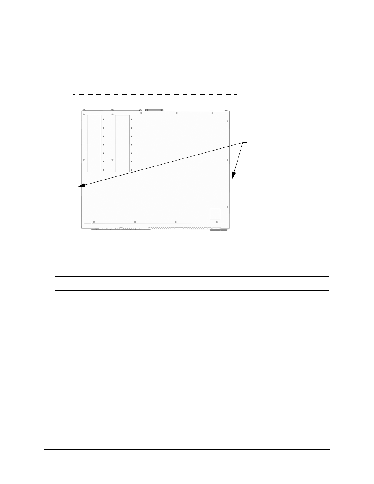
}
}
Rear. 6 inches minimum
at rear of chassis.
Front. 6 inches minimum
at front of chassis.
Sides. 2 inches minimum
at left and right sides.
Airflow Considerations
To ensure proper airflow, be sure that your switch is placed in a well-ventilated area and provide minimum
recommended clearance at the front, back and sides of the switch.
Never obstruct chassis air vents.
Chassis Top View
Note. Clearance is not required at the top and bottom of the chassis.
Mounting the Switch
For information on mounting OmniSwitch 6450 switches, refer to Chapter 3, “OmniSwitch 6450 Chassis and
Hardware Components.”
OmniSwitch 6350 Hardware Users Guide September 2015 page 2-3

Connections and Cabling Getting Started
Connections and Cabling
Once your switch is properly installed, you should connect all network and management cables required for
your network applications. Connections may include:
• DB9-to-RJ-45 cable to the console connector
• Cables to 10/100/1000 Ethernet or SFP ports
Note. For additional information on cabling connections, refer to the OmniSwitch AOS Release 6 Switch
Management Guide.
Serial Connection to the Console Port
The console port provides a serial connection to the switch using a USB connector and is required when
logging into the switch for the first time. By default, this connector provides a DCE console connection.
Serial Connection Default Settings
baud rate 9600
parity none
data bits (word size) 8
stop bits 1
For information on modifying these settings, refer to the OmniSwitch AOS Release 6 Switch
Management Guide.
page 2-4 OmniSwitch 6350 Hardware Users Guide September 2015

Getting Started Booting the Switch
Booting the Switch
Now that you have installed the switch components and connected network and management cables, you can
boot the switch. To boot the switch, plug the po wer supply cord into an easily-accessible, properly grounded
power outlet. (Do not use extension cords.) The switch will power on and boot automatically.
Component LEDs
During the boot process, component LEDs will flash and change color, indi cating different stages of the boot.
Following a successful boot, chassis LEDs should display as follows:
OK1 Solid Green
PRI Solid Green
PWR Solid Green
Note. If the LEDs do not display as indicated, make sure the boot process is complet e. If t he LEDs do not
display as indicated following a complete boot sequence, contact Alcatel-Lucent Customer Support. For
information on LED states, refer to “Chassis Status LEDs” on page 3-19.
Once the switch has completely booted and you have accessed your computer’s terminal emulation software
via the console port, you are ready to lo g in to the switch’s Command Line Interface (CLI) and configure basic
information. Continue to “Your First Login Session” on page 2-6.
OmniSwitch 6350 Hardware Users Guide September 2015 page 2-5

Your First Login Session Getting Started
Your First Login Session
In order to complete the setup process for the switch, you must complete the following steps during your first
login session:
• Log in to the switch
• Unlock session types
• Change the login password
• Set the date and time
• Set optional system information
• Save your changes
Important. You must be connected to the switch via the console port before initiating your first
login session.
Logging In to the Switch
When you first log in to the switch, you will be prompted for a login name and password. Use the switch’s
default settings:
• Login: admin
• Password: switch
The default welcome banner, which includes informatio n such as the current software version and system date,
is displayed followed by the CLI command prompt:
Welcome to the Alcatel-Lucent OmniSwitch 6450
Software Version 6.7.1.80.R01 Development, July 08, 2015.
Copyright(c), ALE USA Inc., 2015. All Rights reserved.
OmniSwitch(TM) is a trademark of Alcatel-Lucent Enterprise registered
in the United States Patent and Trademark Office.
->
Note. A user account includes a login name, password, and user privileges. Privileges determine whether
the user has read or write access to the switch and which commands the user is authorized to execute. For
detailed information on setting up and modifying user accounts, refer to the OmniSwitch AOS Release 6
Switch Management Guide.
page 2-6 OmniSwitch 6350 Hardware Users Guide September 2015

Getting Started Your First Login Session
Unlocking Session Types
Security is a key feature on OmniSwitch 6350 switches. As described on page 2-6, when you access the switch
for the first time, you must use a direct console port connection. All other session types (Telnet, FTP,
WebView, and SNMP) are locked out until they are manually unlocked by the user.
The CLI command used to unlock session types is aaa authentication.
Note. When you unlock session types, you are granting switch access to non-local sessions (e.g., Telnet).
As a result, users who know the correct user login and password will have remote access to th e switc h. For
more information on switch security, refer to the OmniSwitch AOS Release 6 Switch Management Guide.
Unlocking All Session Types
To unlock all session types, enter the following command syntax at the CLI prompt:
-> aaa authentication default local
Unlocking Specified Session Types
You can also unlock session types on a one-by-one basis. For example, to unlock Telnet sessions only, enter
the following command:
-> aaa authentication telnet local
To unlock WebView (HTTP) sessions only, enter the following command:
-> aaa authentication http local
You cannot specify more than one session type in a single command line. However, you can still unlock
multiple session types by using the aaa authentication command in succession. For example:
-> aaa authentication http local
-> aaa authentication telnet local
-> aaa authentication ftp local
Refer to the OmniSwitch CLI Reference Guide for complete aaa authentication command syntax options.
OmniSwitch 6350 Hardware Users Guide September 2015 page 2-7

Your First Login Session Getting Started
Changing the Login Password
Change the login password for admin user sessions by following the steps below:
1 Be sure that you have logged into the switch as user type admin (see “Logging In to the Switch” on
page 2-6).
2 Enter the keyword password and press Enter.
3 Enter your new password at the prompt.
Note. Be sure to remember or securely record all new passwords; overriding configured passwords on an
OmniSwitch is restricted.
4 You will be prompted to re-enter the password. Enter the password a second time.
New password settings are automatically saved in real time to the local user database; the user is not required
to enter an additional command in order to save the password information. Also note that new password
information is retained following a reboot. All subsequent login sessions, including those through the console
port, will require the new password to access the switch.
For detailed information on managing login information, including user names and passwords, refer to the
OmniSwitch AOS Release 6 Switch Management Guide.
Setting the System Time Zone
The switch’s default time zone is UTC. If you require a time zone that is spe cifi c to y ou r region , or if you nee d
to enable Daylight Savings Time (DST) on the switch, you can configure these settings via the system
timezone and system daylight-savings-time commands.
For detailed information on configuring a time zone for the switch, refer to the OmniSwitch AOS Release 6
Switch Management Guide.
Setting the Date and Time
Set the current time for the switch by entering system time, followed by the current time in hh:mm:ss.
To set the current date for the switch, enter system date, followed by the current date in mm/dd/yyyy.
page 2-8 OmniSwitch 6350 Hardware Users Guide September 2015
 Loading...