

Alcatel-Lucent OmniSwitch 6450-P10, OmniSwitch 6450, OmniSwitch 6450-10, OmniSwitch 6450-10L, OmniSwitch 6450-P10L User Manual
...
Part No. 060351-10, Rev. C
July 2012
OmniSwitch 6450 Hardware
Users Guide
www.alcatel-lucent.com

This user guide documents OmniSwitch 6450 hardware, including chassis and associated components. The
specifications described in this guide are subject to change without notice.
Copyright © 2012 by Alcatel-Lucent. All rights reserved. This document may not be reproduced in
whole or in part without the express written permission of Alcatel-Lucent.
®
OmniSwitch
, Alcatel-Lucent® and the Alcatel-Lucent logo are registered trademarks of Alcatel-Lucent.
26801 West Agoura Road
Calabasas, CA 91301
(818) 880-3500 FAX (818) 880-3505
U,S, Customer Support (800) 995-2696
International Customer Support (818) 878-4507
www.alcatel-lucent.com
esd.support@alcatel-lucent.com

Contents
Contents About This Guide ..........................................................................................................ix
Supported Platforms ..........................................................................................................ix
Who Should Read this Manual? .........................................................................................x
When Should I Read this Manual? .....................................................................................x
What is in this Manual? ......................................................................................................x
What is Not in this Manual? ...............................................................................................x
How is the Information Organized? .................................................................................. xi
Documentation Roadmap ......................................................................................... .... ... ..xi
Related Documentation ...................................................................................................xiii
Published / Latest Product Documentation .....................................................................xiv
Technical Support ...........................................................................................................xiv
Chapter 1 OmniSwitch 6450 Switches ......................................................................................1-1
Chassis Configurations ....................................................................................................1-2
10-Port Models .........................................................................................................1-2
24-Port Models .........................................................................................................1-2
48-Port Models .........................................................................................................1-2
Combo Ports ......................................................................................................1-3
Non-combo Fiber Ports .....................................................................................1-3
OmniSwitch 6450 Feature Overview ..............................................................................1-3
Security Features .............................................................................................................1-3
Availability Features .......................................................................................................1-3
Software Rollback .......................................... .... .... .... ..............................................1-3
Hot Swapping ...........................................................................................................1-4
Hardware Monitoring ...............................................................................................1-4
Chapter 2 OmniSwitch 6450 Chassis and Hardware Components ..................................2-1
OmniSwitch 6450-10 ......................................................................................................2-2
Major Components ...................................................................................................2-2
Front Panel ...............................................................................................................2-2
OmniSwitch 6450-10 Rear Panel .............................................................................2-3
OmniSwitch 6450-10 Internal AC Power Supply ....................................................2-3
OmniSwitch 6450-P10 ....................................................................................................2-5
Major Components ...................................................................................................2-5
Front Panel ...............................................................................................................2-5
OmniSwitch 6450-P10 Rear Panel ...........................................................................2-6
OmniSwitch 6450-P10 Internal AC Power Supply ..................................................2-6
OmniSwitch 6450-24 ......................................................................................................2-8
OmniSwitch 6450 Hardware Users Guide July 2012 iii

Contents
Major Components ...................................................................................................2-8
Front Panel ...............................................................................................................2-8
OmniSwitch 6450-24 Rear Panel .............................................................................2-9
OmniSwitch 6450-24 Internal AC Power Supply ....................................................2-9
OmniSwitch 6450-P24 ..................................................................................................2-11
Major Components .................................................................................................2-11
Front Panel .............................................................................................................2-11
OmniSwitch 6450-P24 Rear Panel .........................................................................2-12
OmniSwitch 6450-P24 Internal AC Power Supply ................................................2-12
OmniSwitch 6450-48 ....................................................................................................2-14
Major Components .................................................................................................2-14
Front Panel .............................................................................................................2-14
OmniSwitch 6450-48 Rear Panel ...........................................................................2-15
OmniSwitch 6450-48 Internal AC Power Supply ..................................................2-15
OmniSwitch 6450-P48 ..................................................................................................2-17
Major Components .................................................................................................2-17
Front Panel .............................................................................................................2-17
OmniSwitch 6450-P48 Rear Panel .........................................................................2-18
OmniSwitch 6450-P48 Internal AC Power Supply ................................................2-18
OmniSwitch 6450-U24 .................................................................................................2-20
Major Components .................................................................................................2-20
Front Panel .............................................................................................................2-20
OmniSwitch 6450-U24 Rear Panel ........................................................................2-21
OmniSwitch 6450-U24 Internal AC Power Supply ...............................................2-21
OmniSwitch 6450 LED Status ......................................................................................2-23
Expansion Modules .......................................................................................................2-24
OS6450-GNI-C2 ....................................................................................................2-24
OS6450-GNI-U2 ....................................................................................................2-24
OS6450-XNI-U2 ....................................................................................................2-25
OmniSwitch 6450 Internal Backup Power Supplies .....................................................2-26
PS-90W-AC 90W AC Power Supply .....................................................................2-26
PS-90W-DC 90W DC Power Supply .....................................................................2-26
OmniSwitch 6450 External Backup Power Supplies ....................................................2-27
PS-550W-AC-P External 550W AC PoE Power Supply .......................................2-27
PS-900AC-P External 900W AC PoE Power Supply ............................................2-27
AC Power Cords ...........................................................................................................2-28
Specifications .........................................................................................................2-28
Console Port ..................................................................................................................2-29
Port Pinouts ........................................................... .... .... ............................................... .2-30
RJ-45 Console Port – Connector Pinout ................................................................2-30
10/100 Ethernet Port – RJ-45 Pinout (non-PoE) .................................................... 2-30
Gigabit Ethernet Port – RJ-45 Pinout .....................................................................2-30
10/100/1000 Mbps Power over Ethernet Port – RJ-45 Pinout ..............................2-31
Overtemp Condition .................................................. .... ............................................... .2-31
Dying Gasp ....................................................................................................................2-32
iv OmniSwitch 6450 Hardware Users Guide July 2012

Contents
Scenarios ................................................................................................................2-32
SNMP Trap ......................................................................................................2-32
Syslog Message ...............................................................................................2-32
Link OAM PDU ..............................................................................................2-33
Chapter 3 Mounting OmniSwitch 6450 Switches ................................................................... 3-1
General Installation Recommendations ..........................................................................3-2
Airflow Recommendations ......................................................................................3-2
Mechanical Loading .................................................................................................3-4
Circuit Overloading ..................................................................................................3-4
Reliable Earthing ......................................................................................................3-4
Table-Mounting OS6450 Switches .................................................................................3-4
General Table-Mounting Guidelines ........................................................................3-4
Table-Mounting Installation .....................................................................................3-4
Rack-Mounting 10-Port OS6450 Switches .............................................................. .... ...3-5
Available 10-Port Rack-Mounting Kits ...................................................................3-5
General Rack-Mounting Guidelines .............................................................. ...........3-5
Installing Available Rack Mounting Kits .......................................................................3-6
Installing the OS6450-RM-19-L Rack Mount Kit ...................................................3-6
Installing the OS6450-DUAL-MNT Rack Mount Kit .............................................3-7
Rack-Mounting 24 and 48-Port OS6450 Switches .......................................................3-10
Rack Mounting Steps .............................................................................................3-11
Installing External PoE Power Supplies .......................................................... .... .........3-12
Rack Mounting Power Supplies .............................................................................3-12
Connecting the Power Supply Cable ...............................................................3-13
DC Power Supply Considerations ..........................................................................3-14
Connecting Chassis to Power Source ............................................................................3-14
AC Power Supply Connections .............................................................................. 3-14
Powering On a Chassis ................................................................... .... .............3-14
Chapter 4 Booting OmniSwitch 6450 Switches ...................................................................... 4-1
Booting an OmniSwitch ...........................................................................................4-1
Console Port ....................................................................................................................4-2
Serial Connection Default Settings ..........................................................................4-2
Modifying the Serial Connection Settings ...............................................................4-2
Monitoring the Chassis ...................................................................................................4-4
Checking the Overall Chassis Status ........................................................................4-4
Checking the Temperature Status ............................................................................4-4
Viewing the Power Supply Status ............................................................................4-5
Additional Monitoring Commands ..........................................................................4-5
Using LEDs to Visually Monitor the Chassis ..........................................................4-5
Chapter 5 Managing Power over Ethernet (PoE) .................................................................. 5-1
In This Chapter ................................................................................. .... .... .... ...................5-2
Power over Ethernet Specifications ................................................................................5-3
Viewing PoE Power Supply Status .................................................................................5-4
OmniSwitch 6450 Hardware Users Guide July 2012 v

Contents
Configuring Power over Ethernet Parameters .................................................................5-4
Power over Ethernet Defaults ..................................................................................5-4
Understanding and Modifying the Default Settings .................................................5-4
PoE Class Detection .................................................................................................5-5
Setting the PoE Operational Status ....................................................................5-5
Configuring the Total Power Available to a Port ..............................................5-6
Configuring the Total Power Available to a Switch .........................................5-6
Setting Port Priority Levels ...............................................................................5-7
Understanding Priority Disconnect .................................................................................5-8
Setting Priority Disconnect Status ............................................................................5-8
Disabling Priority Disconnect ...........................................................................5-8
Enabling Priority Disconnect ............................................................................5-8
Priority Disconnect is Enabled; Same Priority Level on All PD .......................5-9
Priority Disconnect is Enabled; Incoming PD Port has Highest Priority Level 5-9
Priority Disconnect is Enabled; Incoming PD Port has Lowest Priority Level 5-9
Priority Disconnect is Disabled .......................................................................5-10
Monitoring Power over Ethernet via CLI .....................................................................5-10
Chapter 6 Managing OmniSwitch 6450 Stacks .....................................................................6-1
In This Chapter ................................................................................. .... .... .... ...................6-1
OmniSwitch 6450 Stacking Specifications ..............................................................6-2
OmniSwitch 6450 Stack Overview .................................................................................6-2
Expansion Modules and Stacking Mode Detection ........................................................6-3
Swapping Expansion Modules .................................................................................6-3
Roles Within the Stack ....................................................................................................6-4
Primary and Secondary Management Modules .......................................................6-4
Primary Management Module Selection ........................................................... 6-7
Secondary Management Module Selection ..................................................... 6-10
Idle Module Role ....................................................................................................6-12
Pass-Through Mode ...............................................................................................6-13
Recovering from Pass-Through Mode (Duplicate Slot Numbers) ..................6-14
Stack Cabling .................................................................... .... ... .....................................6-17
Redundant Stacking Cable Connection ..................................................................6-18
Checking Redundant Stacking Cable Status ..........................................................6-19
Slot Numbering .............................................................................................................6-20
Dynamic Slot Number Assignment ........................................................................6-21
Manual Slot Number Assignment ..........................................................................6-23
Reverting to the Dynamic Slot Numbering Model ..........................................6-24
Hot-Swapping Modules In a Stack ...............................................................................6-25
Removing Switches from an Existing Stack ..........................................................6-25
Inserting Switches Into an Existing Stack ..............................................................6-25
Merging Stacks .......................................................................................................6-26
Reloading Switches .......................................................................................................6-27
Reloading the Primary Management Module ........................................................6-27
Reloading the Secondary Management Module ....................................................6-29
Reloading Switches with Idle Roles .......................................................................6 -31
Reloading Switches in Pass-Through Mode ..........................................................6-31
vi OmniSwitch 6450 Hardware Users Guide July 2012

Contents
Reloading All Switches in a Stack .........................................................................6-32
Software Synchronization During a Full Reload .............................................6-32
Effects of Saved Slot Number Information on the Reload Process .................6-32
Avoiding Split Stacks .............................................................................................6-34
Changing the Secondary Module to Primary ................................................................6-35
Synchronizing Switches in a Stack ...............................................................................6-37
Automatic Synchronization During a Full Reload .................................................6-37
Monitoring the Stack .....................................................................................................6-38
Visually Monitoring the Stack ...............................................................................6-38
CLI Commands Supported on Both Primary and
Secondary Management Modules ..........................................................................6-39
Appendix A Regulatory Compliance and Safety Information .............................................. A-1
Declaration of Conformity: CE Mark ............................................................................A-1
China RoHS: Hazardous Substance Table .....................................................................A-2
Waste Electrical and Electronic Equipment (WEEE) Statement ...................................A-4
Standards Compliance ....................................................................................................A-5
Safety Standards ......................................................................................................A-5
EMC Standards .......................................................................................................A-5
Environmental Standards ........................................................................................ A-5
FCC Class A, Part 15 ..............................................................................................A-6
Canada Class A Statement .................................................................................... ..A-6
JATE ........................................................................................................................ A-6
CISPR22 Class A Warning .....................................................................................A-6
VCCI .......................................................................................................................A-7
Class A Warning for Taiwan and Other Chinese Markets ......................................A-7
Translated Safety Warnings ...........................................................................................A-8
Chassis Lifting Warning ........................................................................ .... ..............A-8
Electrical Storm Warning ........................................................................................A-8
Installation Warning ................................................................................................A-8
Invisible Laser Radiation Warning .........................................................................A-9
Power Disconnection Warning ................................................................................A-9
Proper Earthing Requirement Warning .................................................................A-10
Read Important Safety Information Warning ........................................................ A-11
Restricted Access Location Warning ....................................................................A-11
Wrist Strap Warning ..............................................................................................A-12
Instrucciones de seguridad en español .........................................................................A-13
Advertencia sobre el levantamiento del chasis .....................................................A-13
Advertencia de las tapaderas en blanco .................................................................A-13
Advertencia en caso de tormenta eléctrica ............................................................A-13
Advertencia de instalación ....................................................................................A-13
Advertencia de radiación láser invisible ...............................................................A-13
Advertencia de la batería de litio ...........................................................................A-13
Advertencia sobre la tensión de operación ............................................................A-13
Advertencia sobre la desconexión de la fuente .....................................................A-13
Advertencia sobre una apropiada conexión a tierra ..............................................A-14
Leer “información importante de seguridad” ........................................................ A-14
OmniSwitch 6450 Hardware Users Guide July 2012 vii

Contents
Advertencia de acceso restringido .........................................................................A-14
Advertencia de pulsera antiestática .......................................................................A-14
Clase de seguridad ................................................................................. .... .... .... ....A-14
viii OmniSwitch 6450 Hardware Users Guide July 2012

About This Guide
This OmniSwitch 6450 Hardware Users Guide describes your switch hardware components and basic
switch hardware procedures.
Supported Platforms
The information in this guide applies to the following products:
• OmniSwitch 6450-10 (L)
• OmniSwitch 6450-P10 (L)
• OmniSwitch 6450-24
• OmniSwitch 6450-P24
• OmniSwitch 6450-48
• OmniSwitch 6450-P48
• OmniSwitch 6450-U24
Unsupported Platforms
The information in this guide does not apply to the following products:
• OmniSwitch (original version with no numeric model name)
• OmniSwitch 6250 Series
• OmniSwitch 6400 Series
• OmniSwitch 6600 Series
• OmniSwitch 6800 Series
• OmniSwitch 6850 Series
• OmniSwitch 6855 Series
• OmniSwitch 7700
• OmniSwitch 7800
• OmniSwitch 8800
• OmniSwitch 9000 Series
• OmniStack
• OmniAccess
OmniSwitch 6450 Hardware Users Guide July 2012 page ix

Who Should Read this Manual? About This Guide
Who Should Read this Manual?
The audience for this users guide is network administrators and IT support personnel who need t o con figure, maintain, and monitor switches and routers in a live network. However, anyone wishing to gain
knowledge on the OmniSwitch 6450 hardware will benefit from the material in this guide.
When Should I Read this Manual?
Read this guide as soon as you are ready to familiarize yourself with your switch hardware components.
You should have already stepped through the first login procedures and read the brief hardware overviews
in the OmniSwitch 6450 Getting Started Guide.
You should already be familiar with the very basics of the switch hardware, such as module LEDs and
module installation procedures. This manual will help you understand your switch hardware components
(e.g., chassis, cables, power supplies, etc.) in greater depth.
What is in this Manual?
This users guide includes the following hardware-related information:
• Descriptions of switch configurations.
• Descriptions of “availability” features.
• Descriptions of chassis types (e.g., OmniSwitch 6450-10).
• Instructions for mounting the chassis.
• Descriptions of hardware components (status LEDs, chassis, cables, backup power supplies, etc.).
• Managing a chassis.
• Hardware-related Command Line Interface (CLI) commands
What is Not in this Manual?
The descriptive and procedural information in this manual focuses on switch hardware. It includes information on some CLI commands that pertain directly to hardware configuration, bu t it is not intended as a
software users guide. There are several OmniSwitch 6450 users guides that focus on switch software
configuration. Consult those guides for detailed information and examples for configuring yo ur switch
software to operate in a live network environment. See “Documentation Roadmap” on page -xi and
“Related Documentation” on page -xiii for further information on software configuration guides available
for your switch.
page x OmniSwitch 6450 Hardware Users Guide July 2012

About This Guide How is the Information Organized?
How is the Information Organized?
This users guide provides an overview of OmniSwitch 6450 switches, specifications of the hardware
components, steps for setting up and managing OmniSwitch 6450 switches, and an overview and procedures for managing Power over Ethernet (PoE).
Documentation Roadmap
The OmniSwitch user documentation suite wa s design ed to supply you with information at several critical
junctures of the configuration process.The following section outlines a roadmap of the manuals that will
help you at each stage of the configuration process. Under each stage, we point you to the manual or
manuals that will be most helpful to you.
Stage 1: Using the Switch for the First Time
Pertinent Documentation: Getting Started Guide
Release Notes
The Getting Started Guide provides all the information you need to get your switch up and running the
first time. This guide provides information on unpacking the switch, installing power supplies, unlocking
access control, setting the switch’s IP address, and setting up a password. It also includes succinct overview information on fundamental aspects of the switch, such as hardware LEDs, the software directory
structure, CLI conventions, and web-based management.
At this time you should also familiarize yourself with the Release Notes that accompanied your switch.
This document includes important information on feature limitations that are not included in other user
guides.
Stage 2: Gaining Familiarity with Basic Switch Functions
Pertinent Documentation: Hardware Users Guide
Switch Management Guide
Once you have your switch up and running, you will want to begin investigating basic aspects of its hard
ware and software. Information about switch hardware is provided in the Hardware Users Guide. This
guide provide specifications, illustrations, and descriptions of all hardware components—e.g., chassis,
backup power supplies, etc.
The Switch Management Guide is the primary user guide for the basic software features on a switch. This
guide contains information on the switch directory structure, basic file and directory utilities, switch
access security, SNMP, and web-based management. It is recommended that you read this guide before
connecting your switch to the network.
OmniSwitch 6450 Hardware Users Guide July 2012 page xi

Documentation Roadmap About This Guide
Stage 3: Integrating the Switch Into a Network
Pertinent Documentation: Network Configuration Guide
When you are ready to connect your switch to the network, you will need to learn how the OmniSwitch
implements fundamental softwa re features, such as 802.1Q, VLANs, a nd Spanning Tree. The Network
Configuration Guide contains overview information, procedures and examples on how standard networking technologies are configured in the OmniSwitch.
Anytime
The OmniSwitch CLI Reference Guide contains comprehensive information on all CLI commands
supported by the switch. This guide includes syntax, default, usage, example, related CLI command, and
CLI-to-MIB variable mapping information for all CLI commands supported by the switch. This guide can
be consulted anytime during the configuration process to find detailed and specific information on each
CLI command.
page xii OmniSwitch 6450 Hardware Users Guide July 2012

About This Guide Related Documentation
Related Documentation
The following are the titles and descriptions of OmniSwitch 6450-related user manuals:
• OmniSwitch 6450 Getting Started Guide
Describes the hardware and software procedures for getting an OmniSwitch up and running. Also
provides information on fundamental aspects of OmniSwitch software.
• OmniSwitch 6450 Hardware Users Guide
Detailed technical specifications and procedures for the OmniSwitch chassis and components. This
manual also includes comprehensive information on assembling and managing stacked configurations.
• OmniSwitch 6250/6450 CLI Reference Guide
Complete reference to all CLI commands supported on OmniSwitch 6250/6450 products. Includes
syntax definitions, default values, examples, usage guidelines and CLI-to-MIB variable mappings.
• OmniSwitch 6250/6450 Switch Management Guide
Includes procedures for readying an individual switch for integration into a network. Topics include
the software directory architecture, image rollback protections, authenticated switch access, managing
switch files, system configuration, using SNMP, and using web management software (WebView).
• OmniSwitch 6250/6450 Network Configurat ion Guide
Includes network configuration procedures and descriptive information on all the major software
features and protocols included in the base software package. Chapters cover Layer 2 information
(Ethernet and VLAN configuration), Layer 3 information (routing protocols, such as RIP), security
options (authenticated VLANs), Quality of Service (QoS), and link aggregation.
• OmniSwitch 6250/6450 Transceivers Guide
Includes SFP transceiver specifications and product compatibility information.
• Technical Tips, Field Notices
Includes information published by Alcatel-Lucent’s Customer Support group.
• Release Notes and Upgrade Instructions
Includes open problem reports, feature exceptions, and other important information on the features
supported in the current release and any limitations to their support.
OmniSwitch 6450 Hardware Users Guide July 2012 page xiii

Published / Latest Product Documentation About This Guide
Published / Latest Product Documentation
All user guides for the OmniSwit ch Series are included on the Alcatel-Lucent public website. Thi s web site
also includes user guides for other Alcatel-Lucent Enterprise prod ucts.
The latest user guides can be found on our website at:
http://enterprise.alcatel-lucent.com/?dept=UserGuides&page=Portal
Technical Support
An Alcatel-Lucent service agreement brings your company the assurance of 7x24 no-excuses technical
support. You’ll also receive regular software updates to maintain and maximize your Alcatel-Lucent product’s features and functionality and on-site hardware replacement through our global network of highly
qualified service delivery partners. Additionally, with 24-hour-a-day access to Alcatel-Lucent’s Service
and Support web page, you’ll be able to view and update any case (open or closed) that you have reported
to Alcatel-Lucent’s technical support, open a new case or access helpful release notes, technical bulletins,
and manuals. For more information on Alcatel-Lucent’s Service Programs, see our web page at
service.esd.alcatel-lucent.com, call us at 1-800-995-2696, or email us at esd.support@alcatel-lucent.com.
page xiv OmniSwitch 6450 Hardware Users Guide July 2012

1 OmniSwitch 6450 Switches
OS6450-24
OS6450-10; OS6450-10L
OS6450-P10; OS6450-P10L
OS6450-P24
OS6450-P48
OS6450-U24
OS6450-48
Alcatel-Lucent OmniSwitch 6450 Stackable Gigabit Ethernet LAN switches include 10-port, 24-port and
48-port models.
OmniSwitch 6450-10 offer Fast and Gigabit Ethernet for classroom, workgroup and small enterprise
applications and provide low-power consumption and fanless op eration.
OmniSwitch 6450-24 and OmniSwitch 6450-48 fixed configuration gigabit switches offer optional
upgrade paths for 10 Gigabit Ethernet (GigE) stacking, 10 GigE uplinks and metro Ethernet services.
Power over Ethernet (PoE) is offered on OmniSwitch 6450-P10, OmniSwitch 6450-P24 and
OmniSwitch 6450-P48 models.
OmniSwitch 6450 Hardware Users Guide July 2012 page 1-1

Chassis Configurations OmniSwitch 6450 Switches
Chassis Configurations
10-Port Models
• OmniSwitch 6450-10: Provides eight (8) 10/100/1000BaseT Ethernet ports, two (2) combo ports, two
(2) non-combo SFP ports, and an internal AC power supply.
• OmniSwitch 6450-P10: Provides eight (8) 10/100/1000BaseT Power Over Ethernet (802.3at) ports,
two (2) combo ports, two (2) non-combo SFP ports, and an internal AC power supply.
• OmniSwitch 6450-10L: Provides eight (8) 10/100BaseT Ethernet ports upgradeable to 10/100/
1000BaseT, two (2) combo ports, two (2) non-combo SFP ports, and an internal AC power supply.
• OmniSwitch 6450-P10L: Provides eight (8) 10/100BaseT Power Over Ethernet (802.3at) ports
upgradeable to 10/100/1000BaseT, two (2) combo ports, two (2) non-combo SFP ports, and an internal
AC power supply.
Note. The 10/100BaseT “L” models have the same hardware characteristics as the other models but can be
upgraded to support 10/100/1000BaseT via software license upgrade.
24-Port Models
• OmniSwitch 6450-24: Provides 24 10/100/1000 BaseT ports, 2 fixed SFP+ ports and one expansion
slot for optional stacking or uplink modules. The chassis feat ures fanl ess desi gn and int erna l AC power
with optional internal AC or DC backup power.
• OmniSwitch 6450-P24: Provides 24 PoE 10/100/1000 BaseT ports, 2 fixed SFP+ ports and one
expansion slot for optional stacking or uplink modules. The chassis provides four fans and internal AC
power with optional external AC backup power. (The backup power supply is installed on a separate
1 RU tray for an overall 2 RU configuration.)
• OmniSwitch 6450-U24: Provides 22 100/1000 Base-X SFP ports, 2 combo ports configurable to be
10/100/1000 BaseT or 100/1000 Base-X, 2 fixed SFP+ ports and one expansion slot for optional
stacking or uplink modules. The chassis provides three fans and internal AC power with optional
internal AC or DC backup power.
48-Port Models
• OmniSwitch 6450-48: Provides 48 10/100/1000 BaseT ports, 2 fixed SFP+ ports and one expansion
slot for optional stacking or uplink modules. The chassis provides three fans and internal AC power
with optional internal AC or DC backup power.
• OmniSwitch 6450-P48: Provides 48 PoE 10/100/1000 BaseT ports, 2 fixed SFP+ ports and one
expansion slot for optional stacking or uplink modules. The chassis provides four fans and internal AC
power with optional external AC backup power. (The backup power supply is installed on a separate
1 RU tray for an overall 2 RU configuration.)
page 1-2 OmniSwitch 6450 Hardware Users Guide July 2012

OmniSwitch 6450 Switches OmniSwitch 6450 Feature Overview
Combo Ports
Combo ports are individually configurable to be 10/100/1000BaseT or 100FX/1000X that can support
SFP transceivers for short, long and very long distances.
Non-combo Fiber Ports
The non-combo SFP ports provide uplink capability throug h the use of supported SFP transceivers.
OmniSwitch 6450 Feature Overview
Security Features
OmniSwitch 6450 switches offer extensive security features for network access control, policy
enforcement and attack containment, enabling fully secure networks and OmniVista Network
Management System (NMS) support.
Availability Features
OmniSwitch 6450 switches incorporate advanced Alcatel-Lucent Operating System (AOS) protocols to
ensure high availability for mission critical applications. Availability features are hardware- and softwarebased safeguards that help to prevent the loss of data flow in the unlikely event of a subsystem failure.
In addition, some availability features allow users to maintain or replace hardware components without
powering off the switch or interrupting switch operations. Combined, these features provide added
resiliency and help to ensure that the switch or virtual chassis is consistently available for high-impact
network operations.
Hardware-related availability features include:
• Software Rollback
• Hot Swapping
• Hardware Monitoring
Software Rollback
Software rollback (also referred to as image rollback) essentially allows the switch to return to a prior
“last known good” version of software in the event of a system software problem. The switch controls
software rollback through its resilient directory structure design (i.e., /flash/working and /flash/certified).
For detailed information on the software rollback feature, as well as the switch’s /flash/working and
/flash/certified directories, refer to the “Managing CMM Directory Content” chapter in the OmniSwitch
6250/6450 Switch Management Guide.
OmniSwitch 6450 Hardware Users Guide July 2012 page 1-3

OmniSwitch 6450 Switches Availability Features
Hot Swapping
Hot swapping refers to the action of adding, removing, or rep lacing components without powering off
switches or disrupting other components.This feature facilitates hardware upgrades and maintenance and
allows users to easily replace components in the unlikely event of hardware failure.
The following components can be hot swapped:
• Switches (virtual NI modules) within a virtual chassis stack. Refer to “Hot-Swapping Modules In a
Stack” on page 6-25 for more information.
• 1G uplink modules (“like” kinds only). Refer to “Swapping Expansion Modules” on page 6-3 for
more information.
• 10G stacking modules (“like” kinds only). Refer to “Swapping Expansion Modules” on page 6-3 for
more information.
• Backup power supplies
• Power supply connector cables
• Transceivers. Refer to Omn iSw itc h 6250/6450 Transceivers Guide for more information.
Hardware Monitoring
Automatic Monitoring
Automatic monitoring refers to the switch’s built-in sensors that automatically monitor operations. If an
error is detected (e.g., over-threshold temperature), the switch immediately sends a trap to the user. The
trap is displayed on the console in the form of a text error message.
LEDs
LEDs, which provide visual status information, are provided on the chassis front panel. LEDs are used to
indicate conditions such as hardware and software status, temperature errors, link integrity, data flow, etc.
For detailed LED descriptions, refer to Chapter 2, “OmniSwitch 6450 Chassis and Hardware
Components.”
User-Driven Monitoring
User-driven hardware monitoring refers to CLI commands that are entered by the user in order to access
the current status of hardware components. The user enters “show” commands that output information to
the console. Monitoring information for chassis components, such as the optional back up power supply,
chassis temperature sensor, and chassis fans is provided in Chapter 2, “OmniSwitch 6450 Chassis an d
Hardware Components.” The show commands for all the features are described in detail in th e
OmniSwitch 6250/6450 CLI Reference Guide.
OmniSwitch 6450 Hardware Users Guide July 2012 page 1-4

2 OmniSwitch 6450
Chassis and Hardware
Components
OmniSwitch 6450 switches are available in the chassis configurations as shown in the table below:
OmniSwitch 6450-10(L)
(OS6450-10/OS6450-10L)
OmniSwitch 6450-P10(L)
(OS6450-P10/OS6450P10L)
OmniSwitch 6450-24
(OS6450-24)
OmniSwitch 6450-P24
(OS6450-P24)
OmniSwitch 6450-48
(OS6450-48)
OmniSwitch 6450-P48
(OS6450-P48)
OmniSwitch 6450-U24
(OS6450-U24)
Note. The 10/100BaseT “L” models have the same hardware characteristics as the other models but can be
upgraded to support 10/100/1000BaseT via a software license upgrade.
This chapter includes detailed information on these chassis types. Topics include:
Ten port 10/100/1000BaseT model. Available in 10/100 “L” model.
Ten port 10/100/1000BaseT Power Over Ethernet model. Available in
10/100 “L” model.
Twenty-four port 10/100/1000BaseT model.
Twenty-four port 10/100/1000BaseT Power Over Ethernet model.
Forty-eight port 10/100/1000BaseT model.
Forty-eight port 10/100/1000BaseT Power Over Ethernet model.
Twenty-four port SFP model.
• OmniSwitch 6450 chassis descriptions
• Technical specifications
• Power Supplies
• Cables and power cords
• Console port and pinout specifications
OmniSwitch 6450 Hardware Users Guide July 2012 page 2-1
OmniSwitch 6450-10 OmniSwitch 6450 Chassis and Hardware Components
A
C
D
E
F
G
B
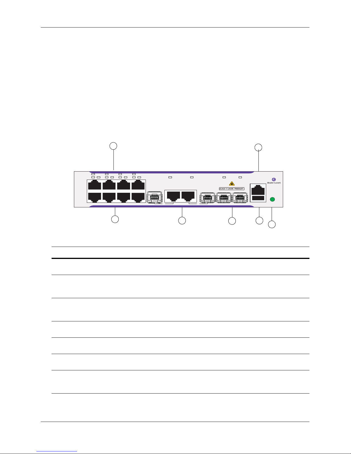
OmniSwitch 6450-10
Major Components
System status LEDs Internal AC Power Supply
(8) Non-combo 10/100/1000Base-T ports Console port (RJ-45)
(2) Non-combo 100/1000BaseX ports USB port (USB 2.0)
(2) Combo 10/100/1000Base-T or
100/1000BaseX ports
Front Panel
Fanless design
OK PRI PWR STK
12 34 56 78 9 10 11 12
Item Description
A
System Status LEDs
Provides status on hardware, software, and power.
B
Console Port
RS-232 console port with an RJ-45 connector. Provides access to the CLI for configuration and
management.
C
10/100/1000BaseT RJ-45 Ports
10/100/1000BaseT non-combo ports. Odd-numbered ports are on top row, even-numbered ports
are on bottom row.
D
10/100/1000BaseT or 100/1000BaseX SFP Combo Ports
Two 10/100/1000BaseT or SFP combo ports for various supported SFP transceivers.
E
SFP Uplink Ports
Two SFP ports to be used for uplinks.
F
G
USB Port
High speed USB 2.0 port.
Push Button
When pushed, all LEDs will turn off and the LED of the Stack ID will remain lit. (Applies to 24and 48-port switches.)
9
OmniSwitch 6450-10 Front Panel
OS6450-10
Console
USB12/STK B11/STK B109
Refer to “OmniSwitch 6450 LED Status” on page 2-23 for LED status information.
page 2-2 OmniSwitch 6450 Hardware Users Guide July 2012

OmniSwitch 6450 Chassis and Hardware Components OmniSwitch 6450-10
A
B
OmniSwitch 6450-10 Rear Panel
Note. The figure shows a pre-production version of the chassis without product, safety, and compliance
information labels. All production versions of the chassis have these labels.
OmniSwitch 6450-10 Rear Panel
Item Description
A
Power Supply Connector
Internal AC power supply.
B
Grounding Block
Type LCD8-10A-L grounding lug
OmniSwitch 6450-10 Internal AC Power Supply
P/S Component Description
Model Internal AC Power Supply
Provides System Power For OmniSwitch 6450-10
Input Voltage Range 100-240 VAC
Rated Frequency 50 to 60 Hz
Maximum Output Power 30 W
Output Voltage 12.0 VDC
Output Current 2.5 A
OmniSwitch 6450 Hardware Users Guide July 2012 page 2-3

OmniSwitch 6450-10 OmniSwitch 6450 Chassis and Hardware Components
OS6450-10 Specifications
10/100/1000BaseT ports 8
Total combo ports 2
SFP uplink ports 2
802.3at PoE ports N/A
Flash memory size 128 MB
RAM memory size 256 MB SDRAM
Chassis Width 8.50 inches (21.5 cm)
Chassis Height 1.73 inches (4.40 cm)
Chassis Depth 11.50 inches (29.21 cm)
Weight 3.66 lbs (1.66 kg)
Operating Humidity 5% to 95%
Storage Humidity 5% to 95%
Operating Temperature 0C to +45C
Storage Temperature -40C to +75C
Default Upper Threshold Tem-
81C
perature
Danger Threshold Temperature 85C
Data rate (RJ-45) 10/100/1000 Mbps
Maximum frame size 9216 bytes
Cable supported
(RJ-45)
10BaseT: unshielded twisted-pair (UTP)
100BaseTX: unshielded twisted-pair (UTP), Category 5, EIA/TIA 568
or shielded twisted-pair (STP), Category 5, 100 ohm
1000BaseT: unshielded twisted-pair (UTP), Category 5e
Maximum cable distance
100 meters
(RJ-45)
page 2-4 OmniSwitch 6450 Hardware Users Guide July 2012
OmniSwitch 6450 Chassis and Hardware Components OmniSwitch 6450-P10
A
B
C
D
E
F
G
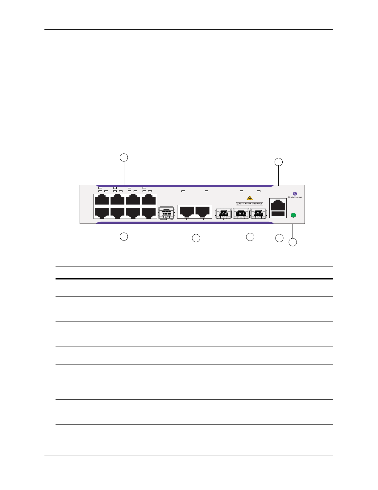
OmniSwitch 6450-P10
Major Components
System status LEDs Internal AC Power Supply
(8) Non-combo 10/100/1000Base-T PoE ports Console port (RJ-45)
(2) Non-combo 100/1000BaseX ports USB port (USB 2.0)
(2) Combo 10/100/1000Base-T or
100/1000BaseX ports
Front Panel
Fanless design
OK PRI PWR STK
12 34 56 78 9 10 11 12
Item Description
A
System Status LEDs
Provides status on hardware, software, and power.
B
Console Port
RS-232 console port with an RJ-45 connector. Provides access to the CLI for configuration and
management.
C
10/100/1000BaseT RJ-45 PoE Ports
10/100/1000BaseT non-combo ports. Odd-numbered ports are on top row, even-numbered ports
are on bottom row.
D
10/100/1000BaseT or 100/1000BaseX SFP Combo Ports
Two 10/100/1000BaseT or SFP combo ports for various supported SFP transceivers.
E
SFP Uplink Ports
Two SFP ports to be used for uplinks.
F
G
USB Port
High speed USB 2.0 port.
Push Button
When pushed, all LEDs will turn off and the LED of the Stack ID will remain lit. (Not currently
supported. Functionality scheduled for future release.)
9
OmniSwitch 6450-P10 Front Panel
OS6450-P10
Console
USB12/STK B11/STK B109
Refer to “OmniSwitch 6450 LED Status” on page 2-23 for LED status information.
OmniSwitch 6450 Hardware Users Guide July 2012 page 2-5

OmniSwitch 6450-P10 OmniSwitch 6450 Chassis and Hardware Components
A
B
OmniSwitch 6450-P10 Rear Panel
Note. The figure shows a pre-production version of the chassis without product, safety, and compliance
information labels. All production versions of the chassis have these labels.
OmniSwitch 6450-P10 Rear Panel
Item Description
A
Power Supply Connector
Internal AC power supply.
B
Grounding Block
Type LCD8-10A-L grounding lug
OmniSwitch 6450-P10 Internal AC Power Supply
P/S Component Description
Model Internal AC Power Supply
Provides System/PoE Power For OmniSwitch 6450-P10
Input Voltage Range 115-230 VAC
Rated Frequency 50 to 60 Hz
Maximum Output Power 120 W
Output Voltage 12.0 VDC / 54.5 VDC
Output Current 2.5 A / 1.65A
page 2-6 OmniSwitch 6450 Hardware Users Guide July 2012

OmniSwitch 6450 Chassis and Hardware Components OmniSwitch 6450-P10
OS6450-P10 Specifications
Total non-combo 10/100/
8 (1-8)
1000BaseT PoE ports per switch
Total combo ports per switch 2 (9-10)
Total non-combo SFP ports per
2 (11-12 in Uplink mode)
switch
Flash memory size 128 MB
RAM memory size 256 MB SDRAM
Chassis Width 8.50 inches (21.5 cm)
Chassis Height 1.73 inches (4.40 cm)
Chassis Depth 11.50 inches (29.21 cm)
Weight 4.56 lbs (2.07 kg)
Operating Humidity 5% to 95%
Storage Humidity 5% to 95%
Operating Temperature 0C to +45C
Storage Temperature -40C to +75C
Default Upper Threshold Tem-
81C
perature
Danger Threshold Temperature 85C
Data rate (RJ-45) 10/100/1000 Mbps
Maximum frame size 9216 bytes
Cable supported
(RJ-45)
10BaseT: unshielded twisted-pair (UTP)
100BaseTX: unshielded twisted-pair (UTP), Category 5, EIA/TIA 568
or shielded twisted-pair (STP), Category 5, 100 ohm
1000BaseT: unshielded twisted-pair (UTP), Category 5e
Maximum cable distance
100 meters
(RJ-45)
OmniSwitch 6450 Hardware Users Guide July 2012 page 2-7
OmniSwitch 6450-24 OmniSwitch 6450 Chassis and Hardware Components
CB
A
D
E
F
G
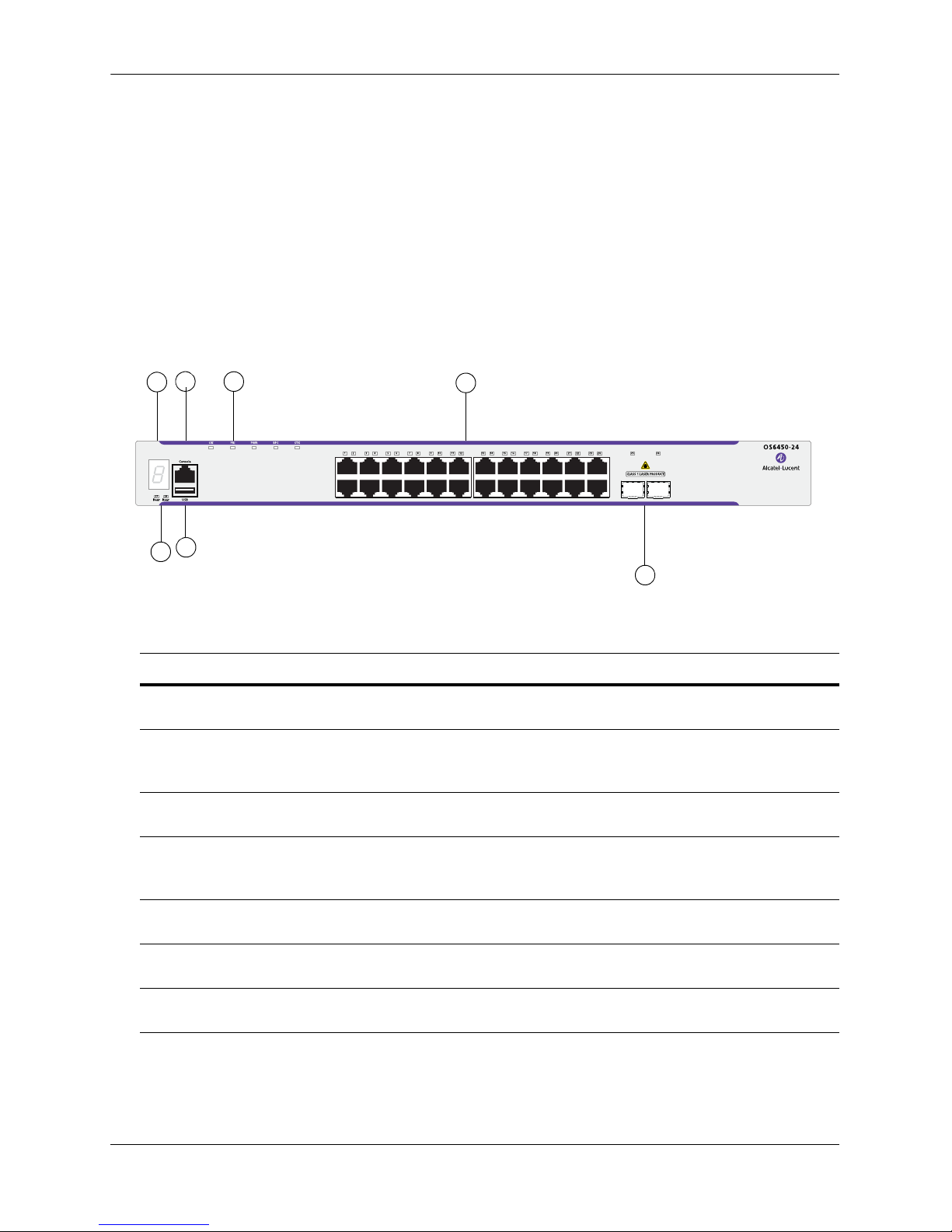
OmniSwitch 6450-24
Major Components
System status LEDs Internal AC Power Supply
(24) Non-combo 10/100/1000Base-T ports Console port (RJ-45)
(2) Non-combo SFP/SFP+ ports USB port (USB 2.0)
Expansion Module Stacking LED
Front Panel
OmniSwitch 6450-24 Front Panel
Item Description
A
Stacking LED
Displays the chassis stack ID.
B
Console Port
RS-232 console port with an RJ-45 connector. Provides access to the CLI for configuration and
management.
C
System Status LEDs
Provides status on hardware, software, and power.
D
10/100/1000BaseT RJ-45 Ports
10/100/1000BaseT non-combo ports. Odd-numbered ports are on top row, even-numbered ports
are on bottom row.
E
Rear Status LEDs
Displays link status for expansion module ports.
F
USB Port
High speed USB 2.0 port.
G
SFP/SFP+ Ports
Two SFP/SFP+ ports to be used for uplinks.
Refer to “OmniSwitch 6450 LED Status” on page 2-23 for LED status information.
page 2-8 OmniSwitch 6450 Hardware Users Guide July 2012
OmniSwitch 6450 Chassis and Hardware Components OmniSwitch 6450-24
A
D
B C
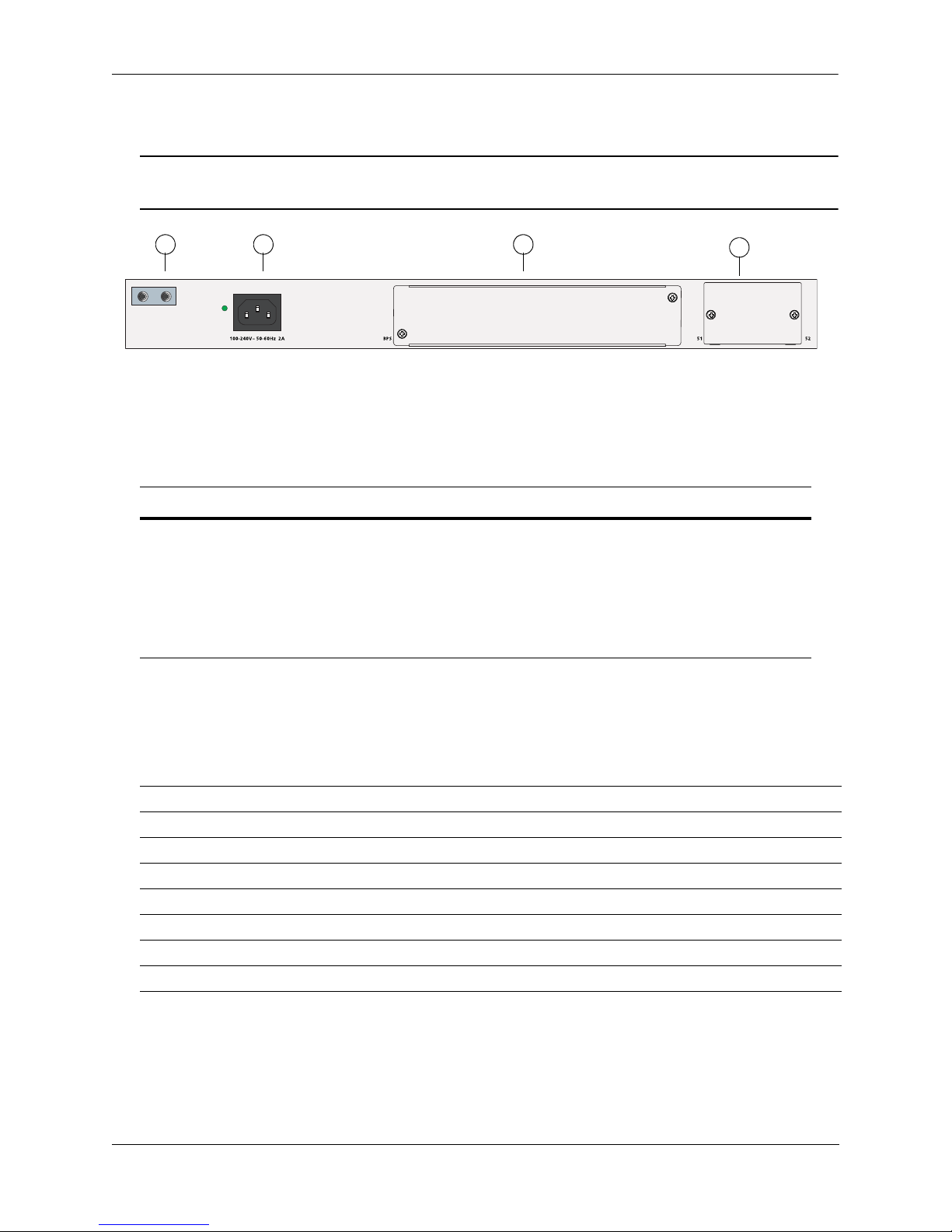
OmniSwitch 6450-24 Rear Panel
Note. The figure shows a pre-production version of the chassis without product, safety, and compliance
information labels. All production versions of the chassis have these labels.
OmniSwitch 6450-24 Rear Panel
Item Description
A
Grounding Block
Type LCD8-10A-L grounding lug
B
Power Supply Connector
Internal AC power supply
C
D
Internal Backup Power Supply Slot
Expansion Module Slot
OmniSwitch 6450-24 Internal AC Power Supply
P/S Component Description
Model Internal AC Power Supply
Provides System Power For OmniSwitch 6450-24
Input Voltage Range 100-240 VAC
Rated Frequency 50 to 60 Hz
Maximum Output Power 65 W
Output Voltage 12.0 VDC
Output Current 5.4 A
OmniSwitch 6450 Hardware Users Guide July 2012 page 2-9

OmniSwitch 6450-24 OmniSwitch 6450 Chassis and Hardware Components
OS6450-24 Specifications
RJ-45 10/100/1000BaseT ports 24
SFP+ Gigabit/10Gigabit uplink
2
ports
Ports per expansion module 2
Max. chassis per stack 8
Flash memory size 128 MB
RAM memory size 256 MB SDRAM
Chassis Width 17.32 inches (44.00 cm)
Chassis Height 1.73 inches (4.40 cm)
Chassis Depth 12.3 inches (31.24 cm)
Weight 9 lbs (4.08 kg)
Operating Humidity 5% to 95%
Storage Humidity 5% to 95%
Operating Temperature 0C to +45C (32F to 113F)
Storage Temperature -40C to +75C (-40F to +167F)
Default Upper Threshold Tem-
81C
perature
Danger Threshold Temperature 85C
Data rate (RJ-45) 10/100/1000 Mbps
Maximum frame size 9216 bytes
Cable supported
(RJ-45)
10BaseT: unshielded twisted-pair (UTP)
100BaseTX: unshielded twisted-pair (UTP), Category 5, EIA/TIA 568
or shielded twisted-pair (STP), Category 5, 100 ohm
1000BaseT: unshielded twisted-pair (UTP), Category 5e
Maximum cable distance
100 meters
(RJ-45)
page 2-10 OmniSwitch 6450 Hardware Users Guide July 2012
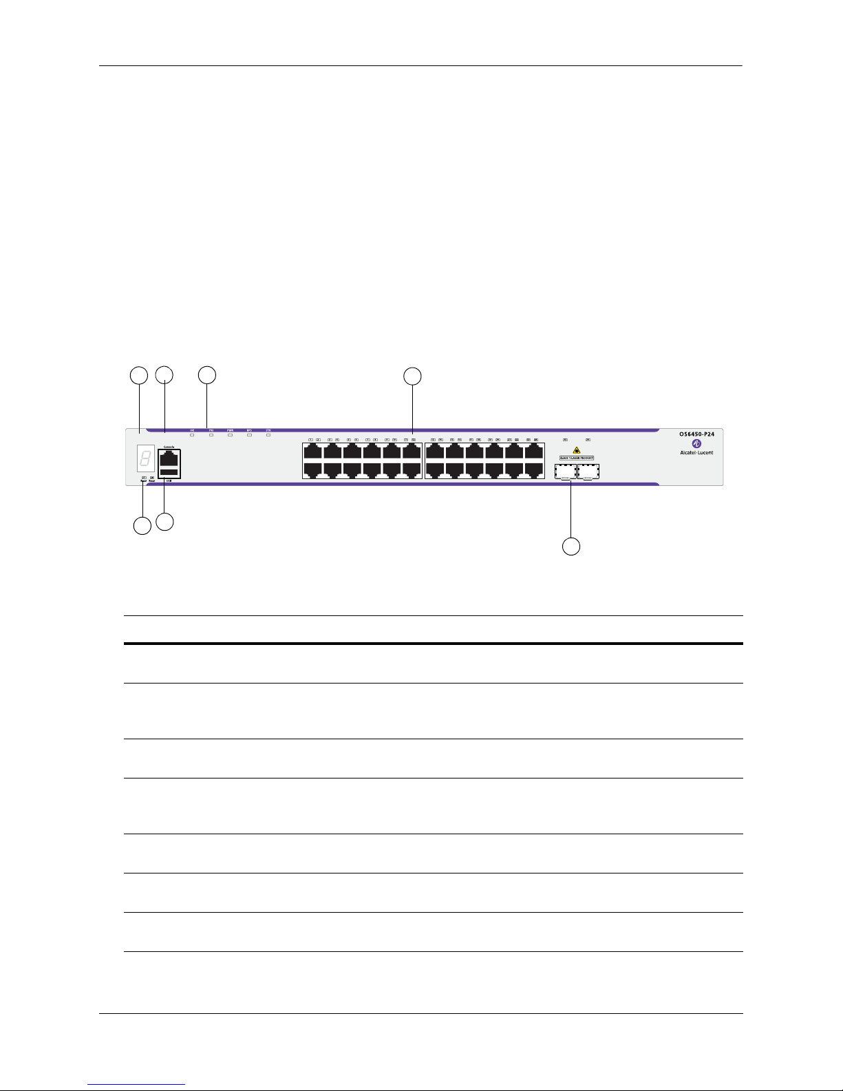
OmniSwitch 6450 Chassis and Hardware Components OmniSwitch 6450-P24
CB
A
D
E
F
G
OmniSwitch 6450-P24
Major Components
System status LEDs Internal AC Power Supply
(24) Non-combo 10/100/1000Base-T 802.3at PoE
ports
(2) Non-combo SFP/SFP+ ports Console port (RJ-45)
Expansion Module USB port (USB 2.0)
Stacking LED
Front Panel
Backup Power Supply (BPS) Connector
OmniSwitch 6450-10 Front Panel
Item Description
A
Stacking LED
Displays the chassis stack ID.
B
Console Port
RS-232 console port with an RJ-45 connector. Provides access to the CLI for configuration and
management.
C
System Status LEDs
Provides status on hardware, software, and power.
D
10/100/1000BaseT RJ-45 PoE Ports
10/100/1000BaseT non-combo ports. Odd-numbered ports are on top row, even-numbered ports
are on bottom row.
E
Rear Status LEDs
Displays link status for expansion module ports.
F
G
USB Port
High speed USB 2.0 port.
SFP/SFP+ Ports
Two SFP/SFP+ ports to be used for uplinks.
Refer to “OmniSwitch 6450 LED Status” on page 2-23 for LED status information.
OmniSwitch 6450 Hardware Users Guide July 2012 page 2-11

OmniSwitch 6450-P24 OmniSwitch 6450 Chassis and Hardware Components
A
D
B C
OmniSwitch 6450-P24 Rear Panel
Note. The figure shows a pre-production version of the chassis without product, safety, and compliance
information labels. All production versions of the chassis have these labels.
OmniSwitch 6450-P24 Rear Panel
Item Description
A
Grounding Block
Type LCD8-10A-L grounding lug
B
Power Supply Connector
Internal AC power supply.
C
D
External Backup or PoE Power Supply Connector
Expansion Module Slot
OmniSwitch 6450-P24 Internal AC Power Supply
P/S Component Description
Model Internal AC Power Supply
Provides System/PoE Power For OmniSwitch 6450-P24
Input Voltage Range 100-240 VAC
Rated Frequency 50 to 60 Hz
Maximum Output Power 530 W
Output Voltage 12.0 VDC / 54.5 VDC
Output Current 10.0 A / 7.6 A
page 2-12 OmniSwitch 6450 Hardware Users Guide July 2012
 Loading...