

Page 1

7750 SR OS
Router Configuration Guide
Software Version: 7750 SR OS 5.0
February 2007
Document Part Number: 93-0073-03-01
*93-0073-03-01*
Page 2

This document is protected by copyright. Except as specifically permitted herein, no portion of the provided information can be
reproduced in any form, or by any means, without prior written permission from Alcatel-Lucent.
Page 3

Table of Contents
Getting Started
Alcatel-Lucent 7750 SR-Series Router Configuration
Process. . . . . . . . . . . . . . . . . . . . . . . . . . . . . . . . . . . . . . . . . . . . . . . . . . . . . . . . . . . . . . . . . . . . . . . . . . . .17
IP Router Configuration
Configuring IP Router Parameters . . . . . . . . . . . . . . . . . . . . . . . . . . . . . . . . . . . . . . . . . . . . . . . . . . . . . . .20
Interfaces. . . . . . . . . . . . . . . . . . . . . . . . . . . . . . . . . . . . . . . . . . . . . . . . . . . . . . . . . . . . . . . . . . . . . . . .20
Network Interface . . . . . . . . . . . . . . . . . . . . . . . . . . . . . . . . . . . . . . . . . . . . . . . . . . . . . . . . . . . . . . .20
System Interface . . . . . . . . . . . . . . . . . . . . . . . . . . . . . . . . . . . . . . . . . . . . . . . . . . . . . . . . . . . . . . .21
IP Addresses . . . . . . . . . . . . . . . . . . . . . . . . . . . . . . . . . . . . . . . . . . . . . . . . . . . . . . . . . . . . . . . . . . . . .22
Creating an IP Address Range. . . . . . . . . . . . . . . . . . . . . . . . . . . . . . . . . . . . . . . . . . . . . . . . . . . . .22
Router ID . . . . . . . . . . . . . . . . . . . . . . . . . . . . . . . . . . . . . . . . . . . . . . . . . . . . . . . . . . . . . . . . . . . . . . .22
Autonomous Systems (AS) . . . . . . . . . . . . . . . . . . . . . . . . . . . . . . . . . . . . . . . . . . . . . . . . . . . . . . . . . .23
Confederations . . . . . . . . . . . . . . . . . . . . . . . . . . . . . . . . . . . . . . . . . . . . . . . . . . . . . . . . . . . . . . . . . . .24
Proxy ARP. . . . . . . . . . . . . . . . . . . . . . . . . . . . . . . . . . . . . . . . . . . . . . . . . . . . . . . . . . . . . . . . . . . . . . .26
Internet Protocol Versions . . . . . . . . . . . . . . . . . . . . . . . . . . . . . . . . . . . . . . . . . . . . . . . . . . . . . . . . . . .27
IPv6 Applications . . . . . . . . . . . . . . . . . . . . . . . . . . . . . . . . . . . . . . . . . . . . . . . . . . . . . . . . . . . . . . .29
IPv6 Provider Edge Router over MPLS (6PE) . . . . . . . . . . . . . . . . . . . . . . . . . . . . . . . . . . . . . . . . .31
Bidirectional Forwarding Detection . . . . . . . . . . . . . . . . . . . . . . . . . . . . . . . . . . . . . . . . . . . . . . . . . . . .33
BFD Control Packet . . . . . . . . . . . . . . . . . . . . . . . . . . . . . . . . . . . . . . . . . . . . . . . . . . . . . . . . . . . . .33
Control Packet Format . . . . . . . . . . . . . . . . . . . . . . . . . . . . . . . . . . . . . . . . . . . . . . . . . . . . . . . . . . .34
Router Configuration Process Overview. . . . . . . . . . . . . . . . . . . . . . . . . . . . . . . . . . . . . . . . . . . . . . . . . . .36
Router Configuration Process Overview. . . . . . . . . . . . . . . . . . . . . . . . . . . . . . . . . . . . . . . . . . . . . . . . . . .37
Router Configuration Process Overview. . . . . . . . . . . . . . . . . . . . . . . . . . . . . . . . . . . . . . . . . . . . . . . . . . .38
Configuration Notes . . . . . . . . . . . . . . . . . . . . . . . . . . . . . . . . . . . . . . . . . . . . . . . . . . . . . . . . . . . . . . . . . .39
Reference Sources . . . . . . . . . . . . . . . . . . . . . . . . . . . . . . . . . . . . . . . . . . . . . . . . . . . . . . . . . . . . . . . .39
Configuring an IP Router with CLI . . . . . . . . . . . . . . . . . . . . . . . . . . . . . . . . . . . . . . . . . . . . . . . . . . . . . . .41
Router Configuration Overview. . . . . . . . . . . . . . . . . . . . . . . . . . . . . . . . . . . . . . . . . . . . . . . . . . . . . . . . . .42
System Interface . . . . . . . . . . . . . . . . . . . . . . . . . . . . . . . . . . . . . . . . . . . . . . . . . . . . . . . . . . . . . . .42
Network Interface . . . . . . . . . . . . . . . . . . . . . . . . . . . . . . . . . . . . . . . . . . . . . . . . . . . . . . . . . . . . . . .42
CLI Command Structure. . . . . . . . . . . . . . . . . . . . . . . . . . . . . . . . . . . . . . . . . . . . . . . . . . . . . . . . . . . . . . .43
List of Commands. . . . . . . . . . . . . . . . . . . . . . . . . . . . . . . . . . . . . . . . . . . . . . . . . . . . . . . . . . . . . . . . . . . .44
Basic Configuration. . . . . . . . . . . . . . . . . . . . . . . . . . . . . . . . . . . . . . . . . . . . . . . . . . . . . . . . . . . . . . . . . . .48
Common Configuration Tasks . . . . . . . . . . . . . . . . . . . . . . . . . . . . . . . . . . . . . . . . . . . . . . . . . . . . . . . . . .49
Configuring a System Name . . . . . . . . . . . . . . . . . . . . . . . . . . . . . . . . . . . . . . . . . . . . . . . . . . . . . . . . .49
Configuring Interfaces . . . . . . . . . . . . . . . . . . . . . . . . . . . . . . . . . . . . . . . . . . . . . . . . . . . . . . . . . . . . . .51
Configuring a System Interface . . . . . . . . . . . . . . . . . . . . . . . . . . . . . . . . . . . . . . . . . . . . . . . . . . . .51
Configuring a Network Interface. . . . . . . . . . . . . . . . . . . . . . . . . . . . . . . . . . . . . . . . . . . . . . . . . . . .51
Configuring IPv6 Parameters . . . . . . . . . . . . . . . . . . . . . . . . . . . . . . . . . . . . . . . . . . . . . . . . . . . . . .53
Configuring IPv6 Over IPv4 Parameters . . . . . . . . . . . . . . . . . . . . . . . . . . . . . . . . . . . . . . . . . . . . .55
Tunnel Ingress Node . . . . . . . . . . . . . . . . . . . . . . . . . . . . . . . . . . . . . . . . . . . . . . . . . . . . . . . . . . . .55
Tunnel Egress Node. . . . . . . . . . . . . . . . . . . . . . . . . . . . . . . . . . . . . . . . . . . . . . . . . . . . . . . . . . . . .61
Router Advertisement. . . . . . . . . . . . . . . . . . . . . . . . . . . . . . . . . . . . . . . . . . . . . . . . . . . . . . . . . . . .66
Configuring Proxy ARP . . . . . . . . . . . . . . . . . . . . . . . . . . . . . . . . . . . . . . . . . . . . . . . . . . . . . . . . . .68
Creating an IP Address Range. . . . . . . . . . . . . . . . . . . . . . . . . . . . . . . . . . . . . . . . . . . . . . . . . . . . .71
Deriving the Router ID. . . . . . . . . . . . . . . . . . . . . . . . . . . . . . . . . . . . . . . . . . . . . . . . . . . . . . . . . . . . . .72
Configuring a Confederation . . . . . . . . . . . . . . . . . . . . . . . . . . . . . . . . . . . . . . . . . . . . . . . . . . . . . . . . .73
7750 SR OS Router Configuration Guide Page 3
Page 4

Table of Contents
Configuring an Autonomous System. . . . . . . . . . . . . . . . . . . . . . . . . . . . . . . . . . . . . . . . . . . . . . . . . . .75
Service Management Tasks . . . . . . . . . . . . . . . . . . . . . . . . . . . . . . . . . . . . . . . . . . . . . . . . . . . . . . . . . . . .76
Changing the System Name . . . . . . . . . . . . . . . . . . . . . . . . . . . . . . . . . . . . . . . . . . . . . . . . . . . . . . . . .76
Modifying Interface Parameters. . . . . . . . . . . . . . . . . . . . . . . . . . . . . . . . . . . . . . . . . . . . . . . . . . . . . . .77
Deleting a Logical IP Interface. . . . . . . . . . . . . . . . . . . . . . . . . . . . . . . . . . . . . . . . . . . . . . . . . . . . . . . .78
IP Router Command Reference . . . . . . . . . . . . . . . . . . . . . . . . . . . . . . . . . . . . . . . . . . . . . . . . . . . . . . . . .79
Configuration Commands . . . . . . . . . . . . . . . . . . . . . . . . . . . . . . . . . . . . . . . . . . . . . . . . . . . . . . . . . . .85
Generic Commands . . . . . . . . . . . . . . . . . . . . . . . . . . . . . . . . . . . . . . . . . . . . . . . . . . . . . . . . . . . . .85
Router Global Commands . . . . . . . . . . . . . . . . . . . . . . . . . . . . . . . . . . . . . . . . . . . . . . . . . . . . . . . .86
Router Interface Commands . . . . . . . . . . . . . . . . . . . . . . . . . . . . . . . . . . . . . . . . . . . . . . . . . . . . . .95
Router Advertisement Commands . . . . . . . . . . . . . . . . . . . . . . . . . . . . . . . . . . . . . . . . . . . . . . . . .116
Show Commands . . . . . . . . . . . . . . . . . . . . . . . . . . . . . . . . . . . . . . . . . . . . . . . . . . . . . . . . . . . . . . . .123
Clear Commands. . . . . . . . . . . . . . . . . . . . . . . . . . . . . . . . . . . . . . . . . . . . . . . . . . . . . . . . . . . . . . . . .160
Debug Commands. . . . . . . . . . . . . . . . . . . . . . . . . . . . . . . . . . . . . . . . . . . . . . . . . . . . . . . . . . . . . . . .164
VRRP
VRRP Overview . . . . . . . . . . . . . . . . . . . . . . . . . . . . . . . . . . . . . . . . . . . . . . . . . . . . . . . . . . . . . . . . . . . .170
VRRP Components . . . . . . . . . . . . . . . . . . . . . . . . . . . . . . . . . . . . . . . . . . . . . . . . . . . . . . . . . . . . . . . . .171
Virtual Router. . . . . . . . . . . . . . . . . . . . . . . . . . . . . . . . . . . . . . . . . . . . . . . . . . . . . . . . . . . . . . . . . . . .171
IP Address Owner . . . . . . . . . . . . . . . . . . . . . . . . . . . . . . . . . . . . . . . . . . . . . . . . . . . . . . . . . . . . . . . .171
Primary and Secondary IP Addresses. . . . . . . . . . . . . . . . . . . . . . . . . . . . . . . . . . . . . . . . . . . . . . . . .172
Virtual Router Master. . . . . . . . . . . . . . . . . . . . . . . . . . . . . . . . . . . . . . . . . . . . . . . . . . . . . . . . . . . . . .172
Virtual Router Backup . . . . . . . . . . . . . . . . . . . . . . . . . . . . . . . . . . . . . . . . . . . . . . . . . . . . . . . . . . . . .173
Owner and Non-Owner VRRP. . . . . . . . . . . . . . . . . . . . . . . . . . . . . . . . . . . . . . . . . . . . . . . . . . . . . . .173
Configurable Parameters. . . . . . . . . . . . . . . . . . . . . . . . . . . . . . . . . . . . . . . . . . . . . . . . . . . . . . . . . . .174
Virtual Router ID (VRID). . . . . . . . . . . . . . . . . . . . . . . . . . . . . . . . . . . . . . . . . . . . . . . . . . . . . . . . .174
Priority . . . . . . . . . . . . . . . . . . . . . . . . . . . . . . . . . . . . . . . . . . . . . . . . . . . . . . . . . . . . . . . . . . . . . .174
IP Addresses . . . . . . . . . . . . . . . . . . . . . . . . . . . . . . . . . . . . . . . . . . . . . . . . . . . . . . . . . . . . . . . . .175
Message Interval and Master Inheritance . . . . . . . . . . . . . . . . . . . . . . . . . . . . . . . . . . . . . . . . . . .176
Skew Time . . . . . . . . . . . . . . . . . . . . . . . . . . . . . . . . . . . . . . . . . . . . . . . . . . . . . . . . . . . . . . . . . . .176
Master Down Interval . . . . . . . . . . . . . . . . . . . . . . . . . . . . . . . . . . . . . . . . . . . . . . . . . . . . . . . . . . .177
Preempt Mode . . . . . . . . . . . . . . . . . . . . . . . . . . . . . . . . . . . . . . . . . . . . . . . . . . . . . . . . . . . . . . . .177
VRRP Message Authentication . . . . . . . . . . . . . . . . . . . . . . . . . . . . . . . . . . . . . . . . . . . . . . . . . . .178
Authentication Data . . . . . . . . . . . . . . . . . . . . . . . . . . . . . . . . . . . . . . . . . . . . . . . . . . . . . . . . . . . .180
Virtual MAC Address . . . . . . . . . . . . . . . . . . . . . . . . . . . . . . . . . . . . . . . . . . . . . . . . . . . . . . . . . . .180
VRRP Advertisement Message IP Address List Verification . . . . . . . . . . . . . . . . . . . . . . . . . . . . .180
Inherit Master VRRP Router’s Advertisement Interval Timer. . . . . . . . . . . . . . . . . . . . . . . . . . . . .181
Policies. . . . . . . . . . . . . . . . . . . . . . . . . . . . . . . . . . . . . . . . . . . . . . . . . . . . . . . . . . . . . . . . . . . . . .181
VRRP Priority Control Policies . . . . . . . . . . . . . . . . . . . . . . . . . . . . . . . . . . . . . . . . . . . . . . . . . . . . . . . . .182
VRRP Virtual Router Policy Constraints . . . . . . . . . . . . . . . . . . . . . . . . . . . . . . . . . . . . . . . . . . . . . . .182
VRRP Virtual Router Instance Base Priority . . . . . . . . . . . . . . . . . . . . . . . . . . . . . . . . . . . . . . . . . . . .182
VRRP Priority Control Policy Delta In-Use Priority Limit . . . . . . . . . . . . . . . . . . . . . . . . . . . . . . . . . . .183
VRRP Priority Control Policy Priority Events. . . . . . . . . . . . . . . . . . . . . . . . . . . . . . . . . . . . . . . . . . . .183
Priority Event Hold-Set Timers. . . . . . . . . . . . . . . . . . . . . . . . . . . . . . . . . . . . . . . . . . . . . . . . . . . .184
Port Down Priority Event . . . . . . . . . . . . . . . . . . . . . . . . . . . . . . . . . . . . . . . . . . . . . . . . . . . . . . . .184
LAG Degrade Priority Event. . . . . . . . . . . . . . . . . . . . . . . . . . . . . . . . . . . . . . . . . . . . . . . . . . . . . .184
Host Unreachable Priority Event . . . . . . . . . . . . . . . . . . . . . . . . . . . . . . . . . . . . . . . . . . . . . . . . . .187
Route Unknown Priority Event . . . . . . . . . . . . . . . . . . . . . . . . . . . . . . . . . . . . . . . . . . . . . . . . . . . .187
VRRP Non-Owner Accessibility . . . . . . . . . . . . . . . . . . . . . . . . . . . . . . . . . . . . . . . . . . . . . . . . . . . . . . . .188
Non-Owner Access Ping Reply . . . . . . . . . . . . . . . . . . . . . . . . . . . . . . . . . . . . . . . . . . . . . . . . . . . . . .188
Page 4 7750 SR OS QoS Configuration Guide
Page 5

T able of Contents
Non-Owner Access Telnet. . . . . . . . . . . . . . . . . . . . . . . . . . . . . . . . . . . . . . . . . . . . . . . . . . . . . . . . . .188
Non-Owner Access SSH . . . . . . . . . . . . . . . . . . . . . . . . . . . . . . . . . . . . . . . . . . . . . . . . . . . . . . . . . . .189
VRRP Configuration Process Overview . . . . . . . . . . . . . . . . . . . . . . . . . . . . . . . . . . . . . . . . . . . . . . . . . .190
VRRP Configuration Components. . . . . . . . . . . . . . . . . . . . . . . . . . . . . . . . . . . . . . . . . . . . . . . . . . . .191
Configuration Notes . . . . . . . . . . . . . . . . . . . . . . . . . . . . . . . . . . . . . . . . . . . . . . . . . . . . . . . . . . . . . . . . .194
General . . . . . . . . . . . . . . . . . . . . . . . . . . . . . . . . . . . . . . . . . . . . . . . . . . . . . . . . . . . . . . . . . . . . . . . .194
Reference Sources . . . . . . . . . . . . . . . . . . . . . . . . . . . . . . . . . . . . . . . . . . . . . . . . . . . . . . . . . . . . . . .194
Configuring VRRP with CLI . . . . . . . . . . . . . . . . . . . . . . . . . . . . . . . . . . . . . . . . . . . . . . . . . . . . . . . . . . .195
VRRP Configuration Overview . . . . . . . . . . . . . . . . . . . . . . . . . . . . . . . . . . . . . . . . . . . . . . . . . . . . . . . . .196
Preconfiguration Requirements. . . . . . . . . . . . . . . . . . . . . . . . . . . . . . . . . . . . . . . . . . . . . . . . . . . . . .196
VRRP CLI Command Structure . . . . . . . . . . . . . . . . . . . . . . . . . . . . . . . . . . . . . . . . . . . . . . . . . . . . . . . .197
List of Commands. . . . . . . . . . . . . . . . . . . . . . . . . . . . . . . . . . . . . . . . . . . . . . . . . . . . . . . . . . . . . . . . . . .199
Basic VRRP Configurations . . . . . . . . . . . . . . . . . . . . . . . . . . . . . . . . . . . . . . . . . . . . . . . . . . . . . . . . . . .204
VRRP Policy . . . . . . . . . . . . . . . . . . . . . . . . . . . . . . . . . . . . . . . . . . . . . . . . . . . . . . . . . . . . . . . . . . . .204
VRRP IES Service Parameters . . . . . . . . . . . . . . . . . . . . . . . . . . . . . . . . . . . . . . . . . . . . . . . . . . . . . .205
VRRP Router Interface Parameters . . . . . . . . . . . . . . . . . . . . . . . . . . . . . . . . . . . . . . . . . . . . . . . . . .206
Common Configuration Tasks . . . . . . . . . . . . . . . . . . . . . . . . . . . . . . . . . . . . . . . . . . . . . . . . . . . . . . . . .207
Creating Interface Parameters . . . . . . . . . . . . . . . . . . . . . . . . . . . . . . . . . . . . . . . . . . . . . . . . . . . . . .208
Configuring VRRP Policy Components . . . . . . . . . . . . . . . . . . . . . . . . . . . . . . . . . . . . . . . . . . . . . . . . . .209
Configuring IES or VPRN Service VRRP Parameters. . . . . . . . . . . . . . . . . . . . . . . . . . . . . . . . . . . . .211
Non-Owner IES or VPRN VRRP Example. . . . . . . . . . . . . . . . . . . . . . . . . . . . . . . . . . . . . . . . . . .212
Owner IES or VPRN VRRP . . . . . . . . . . . . . . . . . . . . . . . . . . . . . . . . . . . . . . . . . . . . . . . . . . . . . .214
Configuring Router Interface VRRP Parameters. . . . . . . . . . . . . . . . . . . . . . . . . . . . . . . . . . . . . . . . .215
Router Interface VRRP Non-Owner . . . . . . . . . . . . . . . . . . . . . . . . . . . . . . . . . . . . . . . . . . . . . . .216
Router Interface VRRP Owner . . . . . . . . . . . . . . . . . . . . . . . . . . . . . . . . . . . . . . . . . . . . . . . . . . .218
VRRP Configuration Management Tasks. . . . . . . . . . . . . . . . . . . . . . . . . . . . . . . . . . . . . . . . . . . . . . . . .219
Modifying a VRRP Policy. . . . . . . . . . . . . . . . . . . . . . . . . . . . . . . . . . . . . . . . . . . . . . . . . . . . . . . . . . .219
Deleting a VRRP Policy . . . . . . . . . . . . . . . . . . . . . . . . . . . . . . . . . . . . . . . . . . . . . . . . . . . . . . . . .220
Modifying Service and Interface VRRP Parameters . . . . . . . . . . . . . . . . . . . . . . . . . . . . . . . . . . . . . .221
Modifying Non-Owner Parameters. . . . . . . . . . . . . . . . . . . . . . . . . . . . . . . . . . . . . . . . . . . . . . . . .221
Modifying Owner Parameters. . . . . . . . . . . . . . . . . . . . . . . . . . . . . . . . . . . . . . . . . . . . . . . . . . . . .221
Deleting VRRP on an Interface or Service. . . . . . . . . . . . . . . . . . . . . . . . . . . . . . . . . . . . . . . . . . .221
VRRP Command Reference. . . . . . . . . . . . . . . . . . . . . . . . . . . . . . . . . . . . . . . . . . . . . . . . . . . . . . . . . . .223
Configuration Commands . . . . . . . . . . . . . . . . . . . . . . . . . . . . . . . . . . . . . . . . . . . . . . . . . . . . . . . . . .227
Interface Configuration Commands . . . . . . . . . . . . . . . . . . . . . . . . . . . . . . . . . . . . . . . . . . . . . . . .227
Priority Policy Commands . . . . . . . . . . . . . . . . . . . . . . . . . . . . . . . . . . . . . . . . . . . . . . . . . . . . . . .242
Priority Policy Event Commands . . . . . . . . . . . . . . . . . . . . . . . . . . . . . . . . . . . . . . . . . . . . . . . . . .245
Priority Policy Port Down Event Commands . . . . . . . . . . . . . . . . . . . . . . . . . . . . . . . . . . . . . . . . .248
Priority Policy LAG Events Commands . . . . . . . . . . . . . . . . . . . . . . . . . . . . . . . . . . . . . . . . . . . . .250
Priority Policy Host Unreachable Event Commands . . . . . . . . . . . . . . . . . . . . . . . . . . . . . . . . . . .253
Priority Policy Route Unknown Event Commands . . . . . . . . . . . . . . . . . . . . . . . . . . . . . . . . . . . . .257
Show Commands . . . . . . . . . . . . . . . . . . . . . . . . . . . . . . . . . . . . . . . . . . . . . . . . . . . . . . . . . . . . . . . .261
Clear Commands. . . . . . . . . . . . . . . . . . . . . . . . . . . . . . . . . . . . . . . . . . . . . . . . . . . . . . . . . . . . . . . . .274
Filter Policies
Filter Policy Configuration Overview. . . . . . . . . . . . . . . . . . . . . . . . . . . . . . . . . . . . . . . . . . . . . . . . . . . . .276
Service and Network Port-based Filtering. . . . . . . . . . . . . . . . . . . . . . . . . . . . . . . . . . . . . . . . . . . . . .276
Filter Policy Entities . . . . . . . . . . . . . . . . . . . . . . . . . . . . . . . . . . . . . . . . . . . . . . . . . . . . . . . . . . . . . . .277
Applying Filter Policies . . . . . . . . . . . . . . . . . . . . . . . . . . . . . . . . . . . . . . . . . . . . . . . . . . . . . . . . . .277
Redirect Policies . . . . . . . . . . . . . . . . . . . . . . . . . . . . . . . . . . . . . . . . . . . . . . . . . . . . . . . . . . . . . . . . .278
7750 SR OS QoS Configuration Guide Page 5
Page 6

Table of Contents
Web Redirection (Captive Portal). . . . . . . . . . . . . . . . . . . . . . . . . . . . . . . . . . . . . . . . . . . . . . . . . .280
Creating Redirect Policies . . . . . . . . . . . . . . . . . . . . . . . . . . . . . . . . . . . . . . . . . . . . . . . . . . . . . . . . . . . .282
Policy Components . . . . . . . . . . . . . . . . . . . . . . . . . . . . . . . . . . . . . . . . . . . . . . . . . . . . . . . . . . . . . . .284
Packet Matching Criteria . . . . . . . . . . . . . . . . . . . . . . . . . . . . . . . . . . . . . . . . . . . . . . . . . . . . . . . . 2 86
Ordering Filter Entries . . . . . . . . . . . . . . . . . . . . . . . . . . . . . . . . . . . . . . . . . . . . . . . . . . . . . . . . . .291
Applying Filters. . . . . . . . . . . . . . . . . . . . . . . . . . . . . . . . . . . . . . . . . . . . . . . . . . . . . . . . . . . . . . . .293
Configuration Notes . . . . . . . . . . . . . . . . . . . . . . . . . . . . . . . . . . . . . . . . . . . . . . . . . . . . . . . . . . . . . . . . .294
MAC Filters . . . . . . . . . . . . . . . . . . . . . . . . . . . . . . . . . . . . . . . . . . . . . . . . . . . . . . . . . . . . . . . . . . . . .294
IP Filters . . . . . . . . . . . . . . . . . . . . . . . . . . . . . . . . . . . . . . . . . . . . . . . . . . . . . . . . . . . . . . . . . . . . . . .295
IPv6 Filters. . . . . . . . . . . . . . . . . . . . . . . . . . . . . . . . . . . . . . . . . . . . . . . . . . . . . . . . . . . . . . . . . . . . . .295
Log Filter . . . . . . . . . . . . . . . . . . . . . . . . . . . . . . . . . . . . . . . . . . . . . . . . . . . . . . . . . . . . . . . . . . . . . . .295
Reference Sources . . . . . . . . . . . . . . . . . . . . . . . . . . . . . . . . . . . . . . . . . . . . . . . . . . . . . . . . . . . . . . .297
Configuring Filter Policies with CLI. . . . . . . . . . . . . . . . . . . . . . . . . . . . . . . . . . . . . . . . . . . . . . . . . . . . . .299
Filter CLI Command Structure . . . . . . . . . . . . . . . . . . . . . . . . . . . . . . . . . . . . . . . . . . . . . . . . . . . . . . . . .300
List of Commands. . . . . . . . . . . . . . . . . . . . . . . . . . . . . . . . . . . . . . . . . . . . . . . . . . . . . . . . . . . . . . . . . . .302
Basic Configuration. . . . . . . . . . . . . . . . . . . . . . . . . . . . . . . . . . . . . . . . . . . . . . . . . . . . . . . . . . . . . . . . . .308
Common Configuration Tasks . . . . . . . . . . . . . . . . . . . . . . . . . . . . . . . . . . . . . . . . . . . . . . . . . . . . . . . . .309
Creating an IP Filter Policy . . . . . . . . . . . . . . . . . . . . . . . . . . . . . . . . . . . . . . . . . . . . . . . . . . . . . . . . .310
IP Filter Policy . . . . . . . . . . . . . . . . . . . . . . . . . . . . . . . . . . . . . . . . . . . . . . . . . . . . . . . . . . . . . . . .310
IP Filter Entry . . . . . . . . . . . . . . . . . . . . . . . . . . . . . . . . . . . . . . . . . . . . . . . . . . . . . . . . . . . . . . . . .312
IP Entry Matching Criteria . . . . . . . . . . . . . . . . . . . . . . . . . . . . . . . . . . . . . . . . . . . . . . . . . . . . . . .316
Creating an IPv6 Filter Policy . . . . . . . . . . . . . . . . . . . . . . . . . . . . . . . . . . . . . . . . . . . . . . . . . . . . . . .317
IPv6 Filter Policy. . . . . . . . . . . . . . . . . . . . . . . . . . . . . . . . . . . . . . . . . . . . . . . . . . . . . . . . . . . . . . .317
IPv6 Filter Entry . . . . . . . . . . . . . . . . . . . . . . . . . . . . . . . . . . . . . . . . . . . . . . . . . . . . . . . . . . . . . . .318
Creating a MAC Filter Policy . . . . . . . . . . . . . . . . . . . . . . . . . . . . . . . . . . . . . . . . . . . . . . . . . . . . . . . .320
MAC Filter Policy . . . . . . . . . . . . . . . . . . . . . . . . . . . . . . . . . . . . . . . . . . . . . . . . . . . . . . . . . . . . . .320
MAC Filter Entry. . . . . . . . . . . . . . . . . . . . . . . . . . . . . . . . . . . . . . . . . . . . . . . . . . . . . . . . . . . . . . .321
MAC Entry Matching Criteria . . . . . . . . . . . . . . . . . . . . . . . . . . . . . . . . . . . . . . . . . . . . . . . . . . . . .322
Creating Filter Log Policies . . . . . . . . . . . . . . . . . . . . . . . . . . . . . . . . . . . . . . . . . . . . . . . . . . . . . . . . .323
Applying Filter Policies . . . . . . . . . . . . . . . . . . . . . . . . . . . . . . . . . . . . . . . . . . . . . . . . . . . . . . . . . . . .324
Apply IP and MAC Filter Policies . . . . . . . . . . . . . . . . . . . . . . . . . . . . . . . . . . . . . . . . . . . . . . . . . .324
Apply an IPv6 Filter Policy to an IES SAP . . . . . . . . . . . . . . . . . . . . . . . . . . . . . . . . . . . . . . . . . . .326
Apply Filter Policies to Network Port . . . . . . . . . . . . . . . . . . . . . . . . . . . . . . . . . . . . . . . . . . . . . . . . .327
Apply an IP Interface . . . . . . . . . . . . . . . . . . . . . . . . . . . . . . . . . . . . . . . . . . . . . . . . . . . . . . . . . . .327
Apply an IPv6 Interface . . . . . . . . . . . . . . . . . . . . . . . . . . . . . . . . . . . . . . . . . . . . . . . . . . . . . . . . .328
Creating a Redirect Policy. . . . . . . . . . . . . . . . . . . . . . . . . . . . . . . . . . . . . . . . . . . . . . . . . . . . . . . . . .329
Configuring Policy-Based Forwarding for Deep Packet Inspection in VPLS. . . . . . . . . . . . . . . . . . . .332
Filter Management Tasks . . . . . . . . . . . . . . . . . . . . . . . . . . . . . . . . . . . . . . . . . . . . . . . . . . . . . . . . . . . . .336
Renumbering Filter Policy Entries . . . . . . . . . . . . . . . . . . . . . . . . . . . . . . . . . . . . . . . . . . . . . . . . . . . .336
Modifying an IP Filter Policy . . . . . . . . . . . . . . . . . . . . . . . . . . . . . . . . . . . . . . . . . . . . . . . . . . . . . . . .338
Modifying an IPv6 Filter Policy . . . . . . . . . . . . . . . . . . . . . . . . . . . . . . . . . . . . . . . . . . . . . . . . . . . . . .340
Modifying a MAC Filter Policy . . . . . . . . . . . . . . . . . . . . . . . . . . . . . . . . . . . . . . . . . . . . . . . . . . . . . . .341
Deleting a Filter Policy. . . . . . . . . . . . . . . . . . . . . . . . . . . . . . . . . . . . . . . . . . . . . . . . . . . . . . . . . . . . .342
From an Ingress SAP. . . . . . . . . . . . . . . . . . . . . . . . . . . . . . . . . . . . . . . . . . . . . . . . . . . . . . . . . . .342
From an Egress SAP . . . . . . . . . . . . . . . . . . . . . . . . . . . . . . . . . . . . . . . . . . . . . . . . . . . . . . . . . . .342
From a Network Interface. . . . . . . . . . . . . . . . . . . . . . . . . . . . . . . . . . . . . . . . . . . . . . . . . . . . . . . .343
From the Filter Configuration . . . . . . . . . . . . . . . . . . . . . . . . . . . . . . . . . . . . . . . . . . . . . . . . .
Modifying a Redirect Policy . . . . . . . . . . . . . . . . . . . . . . . . . . . . . . . . . . . . . . . . . . . . . . . . . . . . . . . . .347
Deleting a Redirect Policy . . . . . . . . . . . . . . . . . . . . . . . . . . . . . . . . . . . . . . . . . . . . . . . . . . . . . . . . . .348
Copying Filter Policies. . . . . . . . . . . . . . . . . . . . . . . . . . . . . . . . . . . . . . . . . . . . . . . . . . . . . . . . . . . . .349
Filter Command Reference. . . . . . . . . . . . . . . . . . . . . . . . . . . . . . . . . . . . . . . . . . . . . . . . . . . . . . . . . . . .351
. . . .346
Page 6 7750 SR OS QoS Configuration Guide
Page 7

T able of Contents
Configuration Commands . . . . . . . . . . . . . . . . . . . . . . . . . . . . . . . . . . . . . . . . . . . . . . . . . . . . . . . . . .357
Generic Commands . . . . . . . . . . . . . . . . . . . . . . . . . . . . . . . . . . . . . . . . . . . . . . . . . . . . . . . . . . . .3 57
Global Filter Commands. . . . . . . . . . . . . . . . . . . . . . . . . . . . . . . . . . . . . . . . . . . . . . . . . . . . . . . . . 3 58
Filter Log Destination Commands . . . . . . . . . . . . . . . . . . . . . . . . . . . . . . . . . . . . . . . . . . . . . . . . .360
Filter Policy Commands . . . . . . . . . . . . . . . . . . . . . . . . . . . . . . . . . . . . . . . . . . . . . . . . . . . . . . . . .3 63
General Filter Entry Commands. . . . . . . . . . . . . . . . . . . . . . . . . . . . . . . . . . . . . . . . . . . . . . . . . . .364
IP Filter Entry Commands . . . . . . . . . . . . . . . . . . . . . . . . . . . . . . . . . . . . . . . . . . . . . . . . . . . . . . .366
MAC Filter Entry Commands . . . . . . . . . . . . . . . . . . . . . . . . . . . . . . . . . . . . . . . . . . . . . . . . . . . . .372
IP Filter Match Criteria . . . . . . . . . . . . . . . . . . . . . . . . . . . . . . . . . . . . . . . . . . . . . . . . . . . . . . . . . .375
MAC Filter Match Criteria. . . . . . . . . . . . . . . . . . . . . . . . . . . . . . . . . . . . . . . . . . . . . . . . . . . . . . . .383
Policy and Entry Maintenance Commands . . . . . . . . . . . . . . . . . . . . . . . . . . . . . . . . . . . . . . . . . .388
Redirect Policy Commands . . . . . . . . . . . . . . . . . . . . . . . . . . . . . . . . . . . . . . . . . . . . . . . . . . . . . .390
Show Commands . . . . . . . . . . . . . . . . . . . . . . . . . . . . . . . . . . . . . . . . . . . . . . . . . . . . . . . . . . . . . . . .395
Clear Commands. . . . . . . . . . . . . . . . . . . . . . . . . . . . . . . . . . . . . . . . . . . . . . . . . . . . . . . . . . . . . . . . .425
Monitor Commands . . . . . . . . . . . . . . . . . . . . . . . . . . . . . . . . . . . . . . . . . . . . . . . . . . . . . . . . . . . . . . .427
Cflowd
Cflowd Overview. . . . . . . . . . . . . . . . . . . . . . . . . . . . . . . . . . . . . . . . . . . . . . . . . . . . . . . . . . . . . . . . . . . .430
Operation. . . . . . . . . . . . . . . . . . . . . . . . . . . . . . . . . . . . . . . . . . . . . . . . . . . . . . . . . . . . . . . . . . . . . . .431
Cflowd Filter Matching. . . . . . . . . . . . . . . . . . . . . . . . . . . . . . . . . . . . . . . . . . . . . . . . . . . . . . . . . . . . .432
Cflowd Configuration Process Overview . . . . . . . . . . . . . . . . . . . . . . . . . . . . . . . . . . . . . . . . . . . . . . . . .434
Cflowd Configuration Components. . . . . . . . . . . . . . . . . . . . . . . . . . . . . . . . . . . . . . . . . . . . . . . . . . . . . .435
Configuration Notes . . . . . . . . . . . . . . . . . . . . . . . . . . . . . . . . . . . . . . . . . . . . . . . . . . . . . . . . . . . . . . . . .437
Reference Sources . . . . . . . . . . . . . . . . . . . . . . . . . . . . . . . . . . . . . . . . . . . . . . . . . . . . . . . . . . . . . . .438
Configuring Cflowd with CLI . . . . . . . . . . . . . . . . . . . . . . . . . . . . . . . . . . . . . . . . . . . . . . . . . . . . . . . . . . .439
Cflowd Configuration Overview . . . . . . . . . . . . . . . . . . . . . . . . . . . . . . . . . . . . . . . . . . . . . . . . . . . . . . . .440
Traffic Sampling. . . . . . . . . . . . . . . . . . . . . . . . . . . . . . . . . . . . . . . . . . . . . . . . . . . . . . . . . . . . . . . . . .440
Collectors . . . . . . . . . . . . . . . . . . . . . . . . . . . . . . . . . . . . . . . . . . . . . . . . . . . . . . . . . . . . . . . . . . . . . .441
Aggregation . . . . . . . . . . . . . . . . . . . . . . . . . . . . . . . . . . . . . . . . . . . . . . . . . . . . . . . . . . . . . . . . . .441
Cflowd CLI Command Structure. . . . . . . . . . . . . . . . . . . . . . . . . . . . . . . . . . . . . . . . . . . . . . . . . . . . . . . .443
List of Commands . . . . . . . . . . . . . . . . . . . . . . . . . . . . . . . . . . . . . . . . . . . . . . . . . . . . . . . . . . . . . . . .444
Basic Cflowd Configuration. . . . . . . . . . . . . . . . . . . . . . . . . . . . . . . . . . . . . . . . . . . . . . . . . . . . . . . . . . . .446
Common Configuration Tasks . . . . . . . . . . . . . . . . . . . . . . . . . . . . . . . . . . . . . . . . . . . . . . . . . . . . . . . . .447
Global Cflowd Components. . . . . . . . . . . . . . . . . . . . . . . . . . . . . . . . . . . . . . . . . . . . . . . . . . . . . . . . .447
Collector Components. . . . . . . . . . . . . . . . . . . . . . . . . . . . . . . . . . . . . . . . . . . . . . . . . . . . . . . . . . . . .447
Configuring Cflowd . . . . . . . . . . . . . . . . . . . . . . . . . . . . . . . . . . . . . . . . . . . . . . . . . . . . . . . . . . . . . . .448
Enabling Cflowd. . . . . . . . . . . . . . . . . . . . . . . . . . . . . . . . . . . . . . . . . . . . . . . . . . . . . . . . . . . . . . . . . .449
Configuring Global Cflowd Parameters . . . . . . . . . . . . . . . . . . . . . . . . . . . . . . . . . . . . . . . . . . . . . . . .450
Configuring Cflowd Collectors . . . . . . . . . . . . . . . . . . . . . . . . . . . . . . . . . . . . . . . . . . . . . . . . . . . . . . .451
Enabling Cflowd on Interfaces and Filters. . . . . . . . . . . . . . . . . . . . . . . . . . . . . . . . . . . . . . . . . . . . . .453
Dependencies . . . . . . . . . . . . . . . . . . . . . . . . . . . . . . . . . . . . . . . . . . . . . . . . . . . . . . . . . . . . . . . .453
Specifying Cflowd Options on an IP Interface . . . . . . . . . . . . . . . . . . . . . . . . . . . . . . . . . . . . . . . . . . .455
Interface Configurations . . . . . . . . . . . . . . . . . . . . . . . . . . . . . . . . . . . . . . . . . . . . . . . . . . . . . . . . .455
Service Interfaces. . . . . . . . . . . . . . . . . . . . . . . . . . . . . . . . . . . . . . . . . . . . . . . . . . . . . . . . . . . . . .456
Specifying Sampling Options in Filter Entries . . . . . . . . . . . . . . . . . . . . . . . . . . . . . . . . . . . . . . . . . . .457
Filter Configurations . . . . . . . . . . . . . . . . . . . . . . . . . . . . . . . . . . . . . . . . . . . . . . . . . . . . . . . . . . . .457
Cflowd Configuration Management Tasks . . . . . . . . . . . . . . . . . . . . . . . . . . . . . . . . . . . . . . . . . . . . . . . .458
Modifying Global Cflowd Components . . . . . . . . . . . . . . . . . . . . . . . . . . . . . . . . . . . . . . . . . . . . . . . .459
Modifying Cflowd Collector Parameters . . . . . . . . . . . . . . . . . . . . . . . . . . . . . . . . . . . . . . . . . . . . . . .460
Cflowd Command Reference . . . . . . . . . . . . . . . . . . . . . . . . . . . . . . . . . . . . . . . . . . . . . . . . . . . . . . . . . .463
7750 SR OS QoS Configuration Guide Page 7
Page 8

Table of Contents
Cflowd Configuration Commands . . . . . . . . . . . . . . . . . . . . . . . . . . . . . . . . . . . . . . . . . . . . . . . . . . . .465
Global Commands . . . . . . . . . . . . . . . . . . . . . . . . . . . . . . . . . . . . . . . . . . . . . . . . . . . . . . . . . . . . .465
Show Commands . . . . . . . . . . . . . . . . . . . . . . . . . . . . . . . . . . . . . . . . . . . . . . . . . . . . . . . . . . . . . . . .471
Clear Commands. . . . . . . . . . . . . . . . . . . . . . . . . . . . . . . . . . . . . . . . . . . . . . . . . . . . . . . . . . . . . . . . .476
Standards and Protocol Support . . . . . . . . . . . . . . . . . . . . . . . . . . . . . . . . . . . . . . . . . . . . . . . . . . . . .477
Index. . . . . . . . . . . . . . . . . . . . . . . . . . . . . . . . . . . . . . . . . . . . . . . . . . . . . . . . . . . . . . . . . . . . . . . . . . . . . . .481
Page 8 7750 SR OS QoS Configuration Guide
Page 9

List of Tables
Getting Started
Table 1: Configuration Process . . . . . . . . . . . . . . . . . . . . . . . . . . . . . . . . . . . . . . . . . . . . . . . . . . . . . . . .17
IP Router Configuration
Table 2: IPv6 Header Field Descriptions. . . . . . . . . . . . . . . . . . . . . . . . . . . . . . . . . . . . . . . . . . . . . . . . . .28
Table 3: BFD Control Packet Field Descriptions. . . . . . . . . . . . . . . . . . . . . . . . . . . . . . . . . . . . . . . . . . . .34
Table 4: CLI Commands to Configure Basic IP Router Parameters. . . . . . . . . . . . . . . . . . . . . . . . . . . . .44
Table 5: Default Route Preferences . . . . . . . . . . . . . . . . . . . . . . . . . . . . . . . . . . . . . . . . . . . . . . . . . . . . .93
VRRP
Table 6: LAG Events. . . . . . . . . . . . . . . . . . . . . . . . . . . . . . . . . . . . . . . . . . . . . . . . . . . . . . . . . . . . . . . .185
Table 7: CLI Commands to Configure a VRRP Policy . . . . . . . . . . . . . . . . . . . . . . . . . . . . . . . . . . . . . .199
Table 8: CLI Commands to Configure IES or VPRN Service VRRP Parameters. . . . . . . . . . . . . . . . . .201
Table 9: Show VRRP Global-Statistics Output . . . . . . . . . . . . . . . . . . . . . . . . . . . . . . . . . . . . . . . . . . . .261
Table 10: Show VRRP Instance Output . . . . . . . . . . . . . . . . . . . . . . . . . . . . . . . . . . . . . . . . . . . . . . . . . .262
Table 11: Show VRRP Policy Output . . . . . . . . . . . . . . . . . . . . . . . . . . . . . . . . . . . . . . . . . . . . . . . . . . . .266
Table 12: Show VRRP Policy Event Output . . . . . . . . . . . . . . . . . . . . . . . . . . . . . . . . . . . . . . . . . . . . . . .2 69
Table 13: Show VRRP Policy Output . . . . . . . . . . . . . . . . . . . . . . . . . . . . . . . . . . . . . . . . . . . . . . . . . . . .273
Filter Policies
Table 14: Applying Filter Policies . . . . . . . . . . . . . . . . . . . . . . . . . . . . . . . . . . . . . . . . . . . . . . . . . . . . . . .277
Table 15: DSCP Name to DSCP Value Table . . . . . . . . . . . . . . . . . . . . . . . . . . . . . . . . . . . . . . . . . . . . .288
Table 16: IP Option Values . . . . . . . . . . . . . . . . . . . . . . . . . . . . . . . . . . . . . . . . . . . . . . . . . . . . . . . . . . . .290
Table 17: MAC Match Criteria Exclusivity Rules. . . . . . . . . . . . . . . . . . . . . . . . . . . . . . . . . . . . . . . . . . . .294
Table 18: CLI Commands to Configure Filter Policies Parameters. . . . . . . . . . . . . . . . . . . . . . . . . . . . . .302
Table 19: Applying Filter Policies . . . . . . . . . . . . . . . . . . . . . . . . . . . . . . . . . . . . . . . . . . . . . . . . . . . . . . .324
Cflowd
Table 20: CLI Commands to Configure Cflowd Parameters. . . . . . . . . . . . . . . . . . . . . . . . . . . . . . . . . . .444
Table 21: Cflowd Configuration Dependencies. . . . . . . . . . . . . . . . . . . . . . . . . . . . . . . . . . . . . . . . . . . . .454
Table 22: Show Cflowd Collector Output Fields . . . . . . . . . . . . . . . . . . . . . . . . . . . . . . . . . . . . . . . . . . . .471
Table 23: Show Cflowd Collector Detailed Output Fields . . . . . . . . . . . . . . . . . . . . . . . . . . . . . . . . . . . . .472
Table 24: Show Cflowd Status Output Fields . . . . . . . . . . . . . . . . . . . . . . . . . . . . . . . . . . . . . . . . . . . . . .475
7750 SR OS Router Configuration Guide Page 9
Page 10

List of Tables
Page 10 7750 SR OS Router Configuration Guide
Page 11

LIST OF FIGURES
IP Router Configuration
Figure 1: Confederation Configuration . . . . . . . . . . . . . . . . . . . . . . . . . . . . . . . . . . . . . . . . . . . . . . . . . . .25
Figure 2: IPv6 Header Format . . . . . . . . . . . . . . . . . . . . . . . . . . . . . . . . . . . . . . . . . . . . . . . . . . . . . . . . . .27
Figure 3: IPv6 Internet Exchange . . . . . . . . . . . . . . . . . . . . . . . . . . . . . . . . . . . . . . . . . . . . . . . . . . . . . . .29
Figure 4: IPv6 Transit Services . . . . . . . . . . . . . . . . . . . . . . . . . . . . . . . . . . . . . . . . . . . . . . . . . . . . . . . . .29
Figure 5: IPv6 Services to Enterprise Customers and Home Users . . . . . . . . . . . . . . . . . . . . . . . . . . . . .30
Figure 6: IPv6 over IPv4 Relay Services . . . . . . . . . . . . . . . . . . . . . . . . . . . . . . . . . . . . . . . . . . . . . . . . . .30
Figure 7: Example of a 6PE Topology within One AS . . . . . . . . . . . . . . . . . . . . . . . . . . . . . . . . . . . . . . . .31
Figure 8: Mandatory Frame Format . . . . . . . . . . . . . . . . . . . . . . . . . . . . . . . . . . . . . . . . . . . . . . . . . . . . .34
Figure 9: IP Router Configuration Flow . . . . . . . . . . . . . . . . . . . . . . . . . . . . . . . . . . . . . . . . . . . . . . . . . . .36
Figure 10: Router Configuration Components . . . . . . . . . . . . . . . . . . . . . . . . . . . . . . . . . . . . . . . . . . . . . . .37
Figure 11: CLI Configuration Context . . . . . . . . . . . . . . . . . . . . . . . . . . . . . . . . . . . . . . . . . . . . . . . . . . . . .43
Figure 12: CLI System Configuration Context . . . . . . . . . . . . . . . . . . . . . . . . . . . . . . . . . . . . . . . . . . . . . . .43
VRRP
Figure 13: VRRP Configuration . . . . . . . . . . . . . . . . . . . . . . . . . . . . . . . . . . . . . . . . . . . . . . . . . . . . . . . . .170
Figure 14: VRRP Configuration and Implementation Flow . . . . . . . . . . . . . . . . . . . . . . . . . . . . . . . . . . . .190
Figure 15: VRRP Policy Configuration Components . . . . . . . . . . . . . . . . . . . . . . . . . . . . . . . . . . . . . . . . .191
Figure 16: Interface VRRP Configuration Components . . . . . . . . . . . . . . . . . . . . . . . . . . . . . . . . . . . . . .192
Figure 17: IES VRRP Configuration Components . . . . . . . . . . . . . . . . . . . . . . . . . . . . . . . . . . . . . . . . . . .193
Figure 18: VRRP Command Structure . . . . . . . . . . . . . . . . . . . . . . . . . . . . . . . . . . . . . . . . . . . . . . . . . . .197
Filter Policies
Figure 19: Web Redirect Traffic Flow . . . . . . . . . . . . . . . . . . . . . . . . . . . . . . . . . . . . . . . . . . . . . . . . . . . .281
Figure 20: Filter Creation and Implementation Flow . . . . . . . . . . . . . . . . . . . . . . . . . . . . . . . . . . . . . . . . .282
Figure 21: Filter Creation and Implementation Flow . . . . . . . . . . . . . . . . . . . . . . . . . . . . . . . . . . . . . . . . .283
Figure 22: Redirect Policy Components . . . . . . . . . . . . . . . . . . . . . . . . . . . . . . . . . . . . . . . . . . . . . . . . . .284
Figure 23: Filter Policy Components . . . . . . . . . . . . . . . . . . . . . . . . . . . . . . . . . . . . . . . . . . . . . . . . . . . . .285
Figure 24: Filtering Process Example . . . . . . . . . . . . . . . . . . . . . . . . . . . . . . . . . . . . . . . . . . . . . . . . . . . .292
Figure 25: Filter Command Structure . . . . . . . . . . . . . . . . . . . . . . . . . . . . . . . . . . . . . . . . . . . . . . . . . . . .300
Figure 26: Redirect Policy Command Structure . . . . . . . . . . . . . . . . . . . . . . . . . . . . . . . . . . . . . . . . . . . .301
Figure 27: Applying an IP Filter to an Ingress Interface . . . . . . . . . . . . . . . . . . . . . . . . . . . . . . . . . . . . . . 3 08
Figure 28: Policy-Based Forwarding for Deep Packet Inspection . . . . . . . . . . . . . . . . . . . . . . . . . . . . . . .332
Cflowd
Figure 29: Basic Cflowd Steps . . . . . . . . . . . . . . . . . . . . . . . . . . . . . . . . . . . . . . . . . . . . . . . . . . . . . . . . .431
Figure 30: V5 and V8 Flow Processing . . . . . . . . . . . . . . . . . . . . . . . . . . . . . . . . . . . . . . . . . . . . . . . . . . .433
Figure 31: Cflowd Configuration and Implementation Flow . . . . . . . . . . . . . . . . . . . . . . . . . . . . . . . . . . . .434
Figure 32: Cflowd Configuration Components . . . . . . . . . . . . . . . . . . . . . . . . . . . . . . . . . . . . . . . . . . . . .435
Figure 33: Router Interface Cflowd Configuration Components . . . . . . . . . . . . . . . . . . . . . . . . . . . . . . . .436
Figure 34: IP Filter Cflowd Configuration Components . . . . . . . . . . . . . . . . . . . . . . . . . . . . . . . . . . . . . . .436
Figure 35: Cflowd Command Structure . . . . . . . . . . . . . . . . . . . . . . . . . . . . . . . . . . . . . . . . . . . . . . . . . . .443
7750 SR OS Router Configuration Guide Page 11
Page 12

List of Figures
Page 12 7750 SR OS Router Configuration Guide
Page 13

About This Guide
This guide describes logical IP routing interfaces, virtual routers, IP and MAC-based filtering, and
cflowd support provided by the 7750 SR OS and presents configuration and implementation
examples.
This document is organized into functional chapters and provides concepts and descriptions of the
implementation flow, as well as Command Line Interface (CLI) syntax and command usage.
Audience
Preface
This manual is intended for network administrators who are responsible for conf iguring the 7750
SR-Series routers. It is assumed that the network administrators have an understanding of
networking principles and configurations. Protocols, standards, and services described in this
manual include the following:
• IP router configuration
• V irtual routers
• IP and MAC-based filters
•Cflowd
7750 SR OS Router Configuration Guide Page 13
Page 14

Preface
List of Technical Publications
The 7750 SR documentation set is composed of the following books:
• 7750 SR OS Basic System Configuration Guide
This guide describes basic system configurations and operations.
• 7750 SR OS System Management Guide
This guide describes system security and access configurations as well as event logging
and accounting logs.
• 7750 SR OS Interface Configuration Guide
This guide describes card, Media Dependent Adapter (MDA), and port provisioning.
• 7750 SR OS Router Configuration Guide
This guide describes logical IP routing interfaces and associated attributes such as an IP
address, port, link aggregation group (LAG) as well as IP and MAC-based filtering,
VRRP, and Cflowd.
• 7750 SR OS Routing Protocols Guide
This guide provides an overview of routing concepts and provides configuration examples
for RIP, OSPF, IS-IS, Multicast, BGP, and route policies.
• 7750 SR OS MPLS Guide
This guide describes how to configure Multiprotocol Label Switching (MPLS) and Label
Distribution Protocol (LDP).
• 7750 SR OS Services Guide
This guide describes how to configure service parameters such as service distribution
points (SDPs), customer information, user services, service mirroring and Operations,
Administration and Management (OAM) tools.
• 7750 SR OS Triple Play Guide
This guide describes Triple Play services and support provided by the 7750 SR and
presents examples to configure and implement various protocols and services.
• 7750 SR Quality of Service Guide
This guide describes how to configure Quality of Service (QoS) policy management.
Page 14 7750 SR OS Rout er Configuration Guide
Page 15

Technical Support
If you purchased a service agreement for your 7750 SR-Series router and related products from a
distributor or authorized reseller, contact the technical support staff for that distributor or reseller
for assistance. If you purchased an Alcatel-Lucent service agreement, contact your welcome center
at:
Web: http://www1.alcatel-lucent.com/comps/pages/carrier_support.jhtml
Preface
7750 SR OS Router Configuration Guide Page 15
Page 16

Preface
Page 16 7750 SR OS Rout er Configuration Guide
Page 17

Getting Started
In This Chapter
This chapter provides process flow information to configure routing entities, virtual routers, IP and
MAC filters, and Cflowd.
Alcatel-Lucent 7750 SR-Series Router Configuration Process
Table 1 lists the tasks necessary to configure logical IP routing interfaces, virtual routers, IP and
MAC-based filtering, and Cflowd.
This guide is presented in an overall logical configuration flow. Each section describes a software
area and provides CLI syntax and command usage to configure parameters for a functional area.
Table 1: Configuration Process
Area Task Chapter
Router
configuration
Protocol
configuration
Reference List of IEEE, IETF, and other proprietary entities. Standards and Protocol Supp ort on
Configure router parameters, including router
interface and addresses, router ID, autonomous
systems, and confederations.
VRRP VRRP on page 169
IP and MAC filters Filter Policies on page 275
Cflowd Cflowd on page 429
IP Router Configuration on page
19
page 715
7750 SR OS Router Configuration Guide Page 17
Page 18

Getting Started
Page 18 7750 SR OS Router Configuration Guide
Page 19

In This Chapter
This chapter provides information about commands required to configure basic router parameters.
Topics in this chapter include:
• Configuring IP Router Parameters on page 20
→ Interfaces on page 20
IP Router Configuration
→ Router ID on page 22
→ Autonomous Systems (AS) on page 23
→ Confederations on page 24
→ Proxy ARP on page 26
→ Internet Protocol Versions on page 27
• Router Configuration Process Overview on page 36
• Configuration Notes on page 39
7750 SR OS Router Configuration Guide Page 19
Page 20

Configuring IP Router Parameters
Configuring IP Router Parameters
In order to provision services on a 7750 SR-Series router, logical IP routing interfaces must be
configured to associate attributes such as an IP address, port or the system with the IP interface.
A special type of IP interface is the system interface. A system interface must have an IP address
with a 32-bit subnet mask. The system interface is used as the router identifier by higher-level
protocols such as OSPF and BGP, unless overwritten by an explicit router ID.
The following router features can be configured:
• Interfaces
• IP Addresses
• Router ID
• Autonomous Systems (AS)
• Confederations
• DHCP Relay
• Internet Protocol Versions
Interfaces
7750 SR-Series routers use different types of interfaces for various functions. Interfaces must be
configured with parameters such as the interface type (network and system) and address. A port is
not associated with a system interface. An interface can be associated with the system (loopback
address).
Network Interface
A network interface (a logical IP routing interface) can be configured on one of the following
entities:
• A physical or logical port
• A SONET/SDH channel
Page 20 7750 SR OS Router Configuration Guide
Page 21

System Interface
The system interface is associated with the network entity (such as a specific router or switch), not
a specific interface. The system interface is also referred to as the loopback address. The system
interface is associated during the configuration of the following entities:
• The termination point of service tunnels
• The hops when configuring MPLS paths and LSPs
• The addresses on a target router for BGP and LDP peering
The system interface is used to preserve connectivity (when routing reconvergence is possible)
when an interface fails or is removed. The system interface is used as the router identifier. A
system interface must have an IP address with a 32-bit subnet mask.
IP Router Configuration
7750 SR OS Router Configuration Guide Page 21
Page 22

Configuring IP Router Parameters
IP Addresses
Creating an IP Address Range
An IP address range can be reserved for exclusive use for services by defining the
config>router>service-prefix command. When the service is configured, the IP address
must be in the range specified as a service prefix. If no service prefix command is configured, then
no limitation exists.
Addresses in the range of a service prefix can be allocated to a network port unless the exclusive
parameter is used. Then, the address range is exclusively reserved for services.
When defining a range that is a superset of a previously defined service prefix, the subset will be
replaced with the superset definition. For example, if a service prefix exists for 10.10.10.0/24, and
a new service prefix is configured as 10.10.0.0/16, then the old address (10.10.10.0/24) will be
replaced with the new address (10.10.0.0/16).
Router ID
When defining a range that is a subset of a previously defined service prefix, the subset will
replace the existing superset, providing addresses used by services are not affected; for example, if
a service prefix exists for 10.10.0.0/16, and a new service prefix is configured as 10.10.10.0/24,
then the 10.10.0.0/16 entry will be removed, provided that no services are configured that use
10.10.x.x addresses other than 10.10.10.x.
The router ID, a 32-bit number, uniquely identifies the router within an autonomous system (AS)
(see Autonomous Systems (AS) on page 23). In protocols such as OSPF, routing information is
exchanged between areas, groups of networks that share routing information. It can be set to be the
same as the loopback address. The router ID is used by both OSPF and BGP routing protocols in
the routing table manager instance.
There are several ways to obtain the router ID. On each 7750 SR-Series router, the router ID can be
derived in the following ways.
• Define the value in the
router ID.
• Configure the system interface with an IP address in the
ip-int-name
config>router router-id context, then the system interface acts as the router ID.
• If neither the system interface or router ID are implicitly specified, then the router ID is
inherited from the last four bytes of the MAC address.
• The router can be derived on the protocol level; for example, BGP.
context. If the router ID is not manually configured in the
config>router router-id context. The value becomes the
config>router>interface
Page 22 7750 SR OS Router Configuration Guide
Page 23

Autonomous Systems (AS)
Networks can be grouped into areas. An area is a collection of network segments within an AS that
have been administratively assigned to the same group. An area’s topology is concealed from the
rest of the AS, which results in a significant reduction in routing traffic.
Routing in the AS takes place on two levels, depending on whether the source and destination of a
packet reside in the same area (intra-area routing) or different areas (inter-area routing). In intraarea routing, the packet is routed solely on information obtained within the area; no routing
information obtained from outside the area can be used. This protects intra-area routing from the
injection of bad routing information.
Routers that belong to more than one area are called area border routers. All routers in an AS do
not have an identical topological database. An area border router has a separate topological
database for each area it is connected to. Two routers, which are not area border routers, belonging
to the same area, have identical area topological databases.
Autonomous systems share routing information, such as routes to each destination and information
about the route or AS path, with other ASs using BGP. Routing tables contain lists of next hops,
reachable addresses, and associated path cost metrics to each router. BGP uses the information and
path attributes to compile a network topology.
IP Router Configuration
7750 SR OS Router Configuration Guide Page 23
Page 24

Configuring IP Router Parameters
Confederations
Configuring confederations is optional and should only be implemented to reduce the IBGP mesh
inside an AS. An AS can be logically divided into smaller groupings called sub-confederations and
then assigned a confederation ID (similar to an autonomous system number). Each subconfederation has fully meshed IBGP and connections to other ASs outside of the confederation.
The sub-confederations have EBGP-type peers to other sub-confederations within the
confederation. They exchange routing information as if they were using IBGP. Parameter values
such as next hop, metric, and local preference settings are preserved. The confederation appears
and behaves like a single AS.
Confederations have the following characteristics.
• A large AS can be sub-divided into sub-confederations.
• Routing within each sub-confederation is accomplished via IBGP.
• EBGP is used to communicate between sub-confederations.
• BGP speakers within a sub-confederation must be fully meshed.
• Each sub-confederation (member) of the confederation has a different AS number. The AS
numbers used are typically in the private AS range of 64512 — 65535.
To migrate from a non-confederation configuration to a confederation configuration requires a
major topology change and configuration modifications on each participating router. Setting BGP
policies to select an optimal path through a confederation requires other BGP modifications.
Page 24 7750 SR OS Router Configuration Guide
Page 25
IP Router Configuration
There are no default confederations. Router confederations must be explicitly created. Figure 1
depicts a confederation configuration example.
Confederation 2002
AS 100
ALA-A
Confederation Member 1
AS 200
ALA-B ALA-C
ALA-D
AS 400
Confederation Member 2
Confederation Member 3
AS 500
ALA-H
AS 300
ALA-E ALA-F
Figure 1: Confederation Configuration
ALA-G
SRSG005
7750 SR OS Router Configuration Guide Page 25
Page 26

Configuring IP Router Parameters
Proxy ARP
Proxy ARP is the technique in which a router answers ARP requests intended for another node.
The router appears to be present on the same network as the “real” node that is the target of the
ARP and takes responsibility for routing packets to the “real” destination. Proxy ARP can help
nodes on a subnet reach remote subnets without configuring routing or a default gateway.
Typical routers only support proxy ARP for directly attached networks; the 7750 SR-Series is
targeted to support proxy ARP for all known networks in the routing instance where the virtual
interface proxy ARP is configured.
In order to support DSLAM and other edge like environments, 7750 SR-Series proxy ARP
supports policies that allow the provider to configure prefix lists that determine for which target
networks proxy ARP will be attempted and prefix lists that determine for which so urce hosts proxy
ARP will be attempted.
In addition, the 7750 SR OS proxy ARP implementation will support the ability to respond for
other hosts within the local subnet domain. This is needed in environments such as DSL where
multiple hosts are in the same subnet but can not reach each other directly.
Static ARP is used when a 7750 SR OS needs to know about a device on an interface that cannot or
does not respond to ARP requests. Thus, the 7750 SR OS configuration can state that if it has a
packet that has a certain IP address to send it to the corresponding ARP address. Use proxy ARP so
the 7750 SR responds to ARP requests on behalf of another device.
Page 26 7750 SR OS Router Configuration Guide
Page 27

Internet Protocol Versions
The 7750 SR OS implements IP routing functionality, providing support for IP version 4 (IPv4)
and IP version 6 (IPv6). IP version 6 (IPv6) (RFC 1883, Internet Protocol, Version 6 (IPv6)) is a
newer version of the Internet Protocol designed as a successor to IP version 4 (IPv4) (RFC-791,
Internet Protocol). The changes from IPv4 to IPv6 effect the following categories:
• Expanded addressing capabilities — IPv6 increases the IP address size from 32 bits (IPv4)
to 128 bits, to support more levels of addressing hierarchy, a much greater number of
addressable nodes, and simpler auto-configuration of addresses. The scalability of
multicast routing is improved by adding a scope field to multicast addresses. Also, a new
type of address called an anycast address is defined that is used to send a packet to any one
of a group of nodes.
• Header format simplification — Some IPv4 header fields have been dropped or made
optional to reduce the common-case processing cost of packet handling and to limit the
bandwidth cost of the IPv6 header.
• Improved support for extensions and options — Changes in the way IP header options are
encoded allows for more efficient forwarding, less stringent limits on the length of
options, and greater flexibility for introducing new options in the future.
IP Router Configuration
• Flow labeling capability — The capability to enable the labeling of packets belonging to
particular traffic flows for which the sender requests special handling, such as non-default
quality of service or “real-time” service was added in IPv6.
• Authentication and privacy capabilities — Extensions to support authentication, data
integrity, and (optional) data confidentiality are specified for IPv6.
+-+-+-+-+-+-+-+-+-+-+-+-+-+-+-+-+-+-+-+-+-+-+-+-+-+-+-+-+-+-+-+-+
|Version| Prio. | Flow Label |
+-+-+-+-+-+-+-+-+-+-+-+-+-+-+-+-+-+-+-+-+-+-+-+-+-+-+-+-+-+-+-+-+
| Payload Length | Next Header | Hop Limit |
+-+-+-+-+-+-+-+-+-+-+-+-+-+-+-+-+-+-+-+-+-+-+-+-+-+-+-+-+-+-+-+-+
| |
+ +
| |
+ Source Address +
| |
+ +
| |
+-+-+-+-+-+-+-+-+-+-+-+-+-+-+-+-+-+-+-+-+-+-+-+-+-+-+-+-+-+-+-+-+
| |
+ +
| |
+ Destination Address +
| |
+ +
| |
+-+-+-+-+-+-+-+-+-+-+-+-+-+-+-+-+-+-+-+-+-+-+-+-+-+-+-+-+-+-+-+-+
Figure 2: IPv6 Header Format
7750 SR OS Router Configuration Guide Page 27
Page 28

Configuring IP Router Parameters
Table 2: IPv6 Header Field Descriptions
Field Description
Version 4-bit Internet Protocol version number = 6.
Prio. 4-bit priority value.
Flow Label 24-bit flow label.
Payload Length 16-bit unsigned integer. The length of payload, for example, the rest of the packet
following the IPv6 header, in octets. If the value is zero, the payload length is
carried in a jumbo payload hop-by-hop option.
Next Header 8-bit selector. Identifies the type of header immediately following the IPv6 header.
This field uses the same values as the IPv4 protocol field.
Hop Limit 8-bit unsigned integer. Decremented by 1 by each node that forwards the packet.
The packet is discarded if the hop limit is decremented to zero.
Source Address 128-bit address of the originator of the packet.
Destination Address 128-bit address of the intended recipient of the packet (possibly not the ultimate
recipient if a routing header is present).
Page 28 7750 SR OS Router Configuration Guide
Page 29
IPv6 Applications
Examples of the IPv6 applications supported by the 7750 SR OS include:
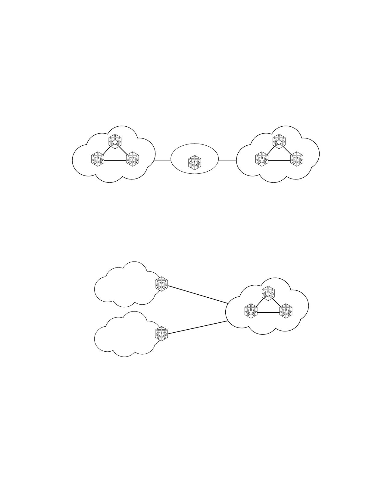
• IPv6 Internet exchange peering — Figure 3 shows an IPv6 Internet exchange where
multiple ISPs peer over native IPv6.
IP Router Configuration
IPv6 IX
ISP A
Peering
ISP B
Figure 3: IPv6 Internet Exchange
• IPv6 transit services — Figure 4 shows IPv6 transit provided by an ISP.
Customer 1
2001:0410:0001:/48
ISP
2001:0410::/32
Customer 2
2001:0410:0002:/4
IPIPE_007
IPIPE_008
Figure 4: IPv6 Transit Services
7750 SR OS Router Configuration Guide Page 29
Page 30
Configuring IP Router Parameters
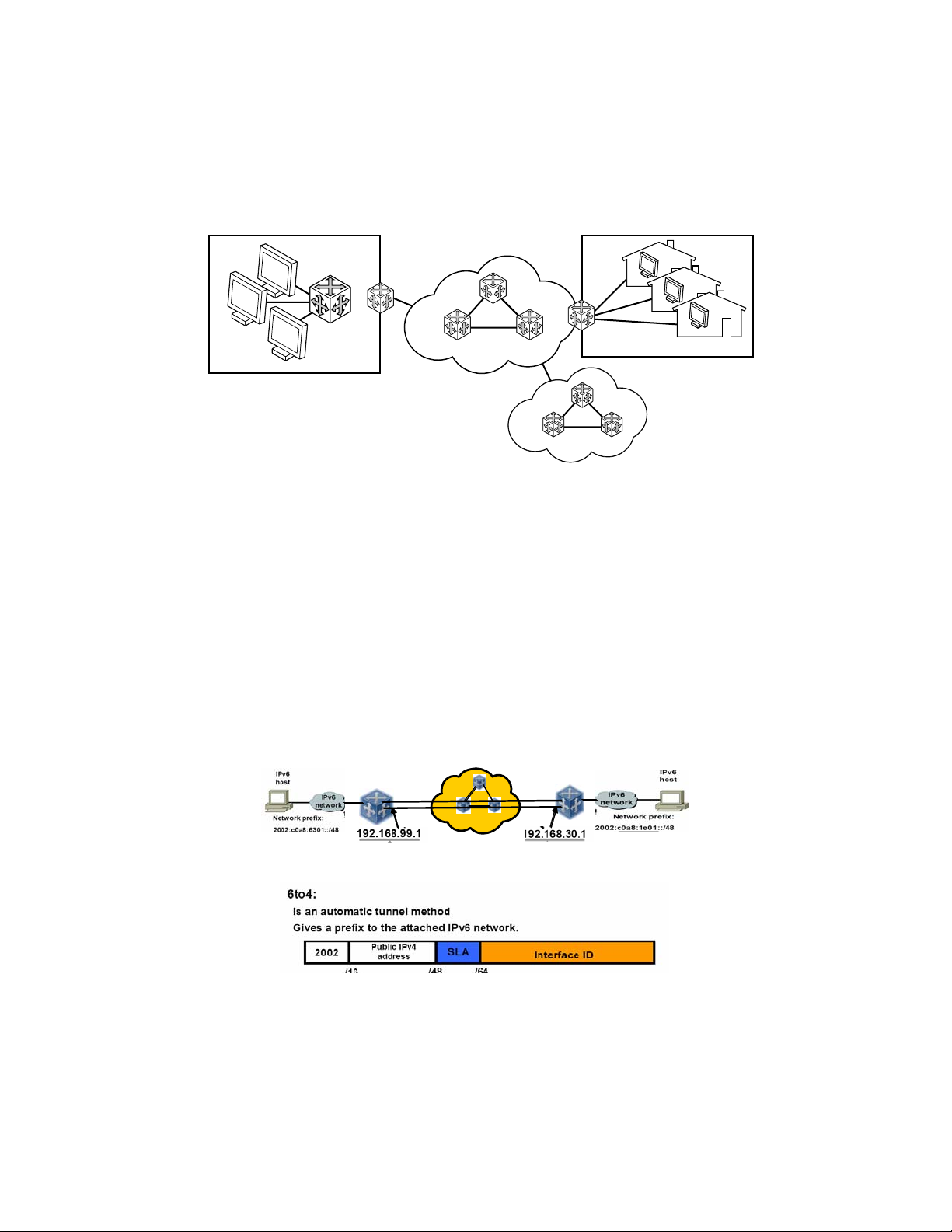
• IPv6 services to enterprise customers and home users — Figure 5 shows IPv6 connectivity
to enterprise and home broadband users.
Enterprise
DSL, Cable
FTTH
IPv6 Core
IPv6 Broadband Users
ISP
IPIPE_009
Figure 5: IPv6 Services to Enterprise Customers and Home Users
• IPv6 over IPv4 relay services — IPv6 over IPv4 tunnels are one of many IPv6 transition
methods to support IPv6 in an environment where not only IPv4 exists but native IPv6
networks depend on IPv4 for greater IPv6 connectivity. 7750 SR OS supports dynamic
IPv6 over IPv4 tunneling. The ipv4 source and destination address are taken from
configuration, the source address is the ipv4 system address and the ipv4 destination is the
next hop from the configured 6over4 tunnel.
IPv6 over IPv4 is an automatic tunnel method that gives a prefix to the attached IPv6
network. Figure 6 shows IPv6 over IPv4 tunneling to transition from IPv4 to IPv6.
6to4
6to4
IPv4 Clo u d
Figure 6: IPv6 over IPv4 Relay Services
Page 30 7750 SR OS Router Configuration Guide
Page 31

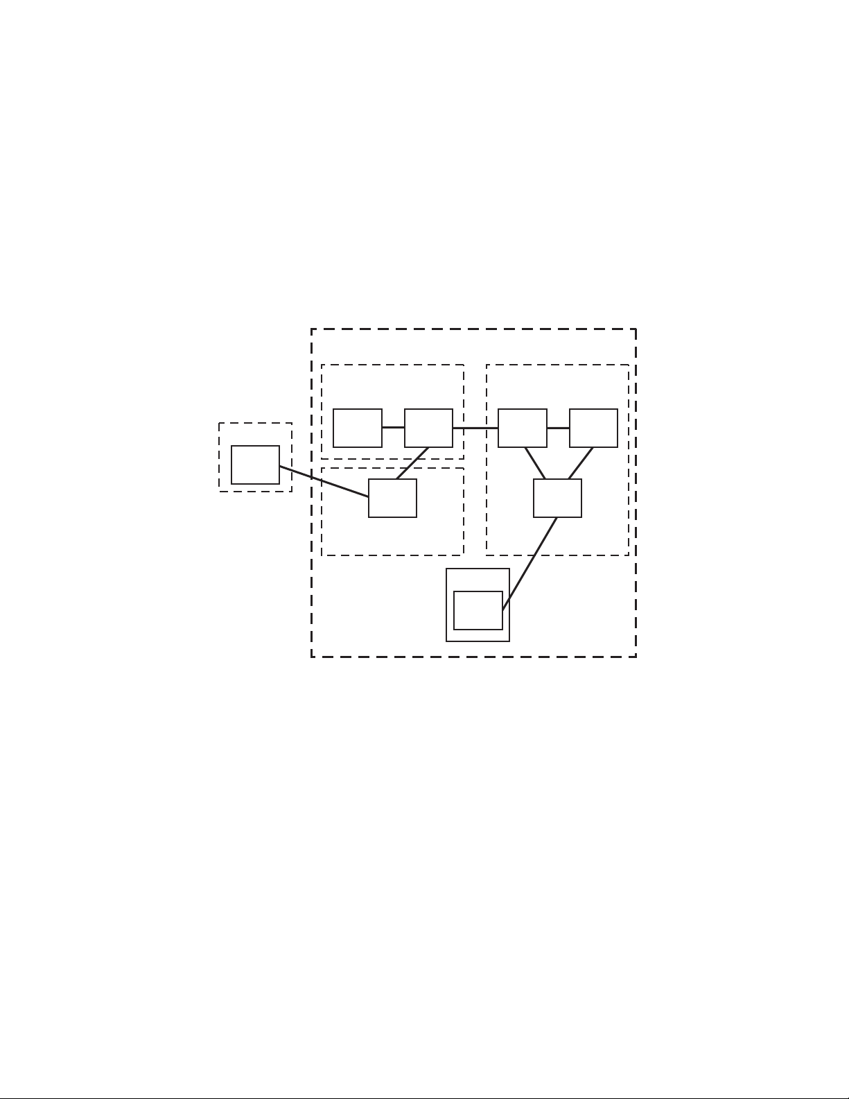
IPv6 Provider Edge Router over MPLS (6PE)
6PE allows IPv6 domains to communicate with each other over an IPv4 MPLS core network. This
architecture requires no backbone infrastructure upgrades and no reconfiguration of core routers,
because forwarding is purely based on MPLS labels. 6PE is a cost effective solution for IPv6
deployment.
IP Router Configuration
Figure 7: Example of a 6PE Topology within One AS
6PE Control Plane Support
The 6PE MP-BGP routers support:
• IPv4/IPv6 dual-stack
• MP-BGP can be used between 6PE routers to exchange IPv6 reachability information.
→ The 6PE routers exchange IPv6 prefixes over MP-BGP sessions running over IPv4
transport. The MP-BGP AFI used is IPv6 (value 2).
→ An IPv4 address of the 6PE router is encoded as an IPv4-mapped IPv6 address in the
BGP next-hop field of the IPv6 NLRI. By default, the IPv4 address that is used for
peering is used. It is configurable through the route policies.
→ The 6PE router binds MPLS labels to the IPv6 prefixes it advertises. The SAFI used in
MP-BGP is the SAFI (value 4) label. The 7750 SR-Series router uses the IPv6 Explicit
Null (value 2) label for all the IPv6 prefixes that it advertises and can accept an
arbitrary label from its peers.
7750 SR OS Router Configuration Guide Page 31
Page 32

Configuring IP Router Parameters
• LDP is used to create the MPLS full mesh between the 6PE routers and the IPv4 addresses
that are embedded in the next-hop field are reachable by LDP LSPs. The ingress 6PE
router uses the LDP LSPs to reach remote 6PE routers.
6PE Data Plane Support
The ingress 6PE router can push two MPLS labels to send the packets to the egress 6PE router. The
top label is an LDP label used to reach the egress 6PE router. The bottom label is advertised in MPBGP by the remote 6PE router. Typically, the IPv6 explicit null (value 2) label is used but an
arbitrary value can be used when the remote 6PE router is from a vendor other than AlcatelLucent.
The egress 6PE router pops the top LDP tunnel label. It sees the IPv6 explicit null label, which
indicates an IPv6 packet is encapsulated. It also pops the IPv6 explicit null label and performs an
IPv6 route lookup to find out the next hop for the IPv6 packet.
Page 32 7750 SR OS Router Configuration Guide
Page 33

Bidirectional Forwarding Detection
Bidirectional Forwarding Detection (BFD) is a light-weight, low-overhead, short-duration
detection of failures in the path between two systems. If a system stops receiving BFD messages
for a long enough period (based on configuration) it is assumed that a failure along th e path has
occurred and the associated protocol or service is notified of the failure.
BFD can provide a mechanism used for liveness detection over any media, at any protocol layer,
with a wide range of detection times and overhead, to avoid a prolifer ation of different methods.
There are two modes of operation for BFD:
• Asynchronous mode — Uses periodic BFD control messages to test the path between
systems.
• Demand mode — Does not send periodic messages. BFD control messages are only sent
when either system feels it needs to again verify connectivity , in which case, it transmits a
short sequence of BFD messages and then stops.
IP Router Configuration
A path is only declared operational when two-way communications has been established between
both systems.
A separate BFD session is created for each communications path and data protocol in use between
two systems.
In addition to the two operational modes, there is also an echo function defined within draft-ietf-
bfd-base-04.txt, Bidire ct ional Forwarding Detection, that allows either of the two systems to send
a sequence of BFD echo packets to the other system, which loops them back within that system’s
forwarding plane. If a number of these echo packets are lost then the BFD session is declared
down.
BFD Control Packet
The base BFD specification does not specify the encapsulation type to be used for sending BFD
control packets. Instead it is left to the implementers to use the appropriate encapsulation type for
the medium and network. The encapsulation for BFD over IPv4 and IPv6 networks is specified in
draft-ietf-bfd-v4v6-1hop-04.txt, BFD for IPv4 and IPv6 (Single Hop). This specification requires
that BFD control packets be sent over UDP with a destination port number of 3784 and the source
port number must be within the range 49152 to 65535.
In addition, the TTL of all transmitted BFD packets must have an IP TTL of 255. All BFD packets
received must have an IP TTL of 255 if authentication is not enabled. If authentication is enabled,
the IP TTL should be 255 but can still be processed if it is not (assuming the packet passes the
enabled authentication mechanism).
7750 SR OS Router Configuration Guide Page 33
Page 34

Configuring IP Router Parameters
If multiple BFD sessions exist between two nodes, the BFD discriminator is used to de-multiplex
the BFD control packet to the appropriate BFD session.
Control Packet Format
The BFD control packet has 2 sections, a mandatory section and an optional authentication section.
0 1 2 3
0 1 2 3 4 5 6 7 8 9 0 1 2 3 4 5 6 7 8 9 0 1 2 3 4 5 6 7 8 9 0 1
+-+-+-+-+-+-+-+-+-+-+-+-+-+-+-+-+-+-+-+-+-+-+-+-+-+-+-+-+-+-+-+-+
|Vers | Diag |Sta|P|F|C|A|D|R| Detect Mult | Length |
+-+-+-+-+-+-+-+-+-+-+-+-+-+-+-+-+-+-+-+-+-+-+-+-+-+-+-+-+-+-+-+-+
| My Discriminator |
+-+-+-+-+-+-+-+-+-+-+-+-+-+-+-+-+-+-+-+-+-+-+-+-+-+-+-+-+-+-+-+-+
| Your Discriminator |
+-+-+-+-+-+-+-+-+-+-+-+-+-+-+-+-+-+-+-+-+-+-+-+-+-+-+-+-+-+-+-+-+
| Desired Min TX Interval |
+-+-+-+-+-+-+-+-+-+-+-+-+-+-+-+-+-+-+-+-+-+-+-+-+-+-+-+-+-+-+-+-+
| Required Min RX Interval |
+-+-+-+-+-+-+-+-+-+-+-+-+-+-+-+-+-+-+-+-+-+-+-+-+-+-+-+-+-+-+-+-+
| Required Min Echo RX Interval |
+-+-+-+-+-+-+-+-+-+-+-+-+-+-+-+-+-+-+-+-+-+-+-+-+-+-+-+-+-+-+-+-+
Figure 8: Mandatory Frame Format
Table 3: BFD Control Packet Field Descriptions
Field Description
Vers The version number of the protocol. The initial protocol version is 0.
Diag A diagnostic code specifying the local system’s reason for the last transition of the
session from Up to some other state.
Possible values are:
0-No diagnostic
1-Control detection time expired
2-Echo function failed
3-Neighbor signaled session down
4-Forwarding plane reset
5-Path down
6-Concatenated path down
7-Administratively down
H Bit The “I Hear You” bit. This bit is set to 0 if the transmitting system either is not
receiving BFD packets from the remote system, or is in the process of tearing down
the BFD session for some reason. Otherwise, during normal operation, it is set to 1.
Page 34 7750 SR OS Router Configuration Guide
Page 35

IP Router Configuration
Table 3: BFD Control Packet Field Descriptions (Continued)
Field Description
D Bit The “demand mode” bit. If set, the transmitting system wishes to operate in demand
mode.
P Bit The poll bit. If set, the transmitting system is requesting verification of
connectivity, or of a parameter change.
F Bit The final bit. If set, the transmitting system is responding to a received BFD control
packet that had the poll (P) bit set.
Rsvd Reserved bits. These bits must be zero on transmit and ignored on receipt.
Detect Mult Detect time multiplier. The negotiated transmit interval, multiplied by this value,
provides the detection time for the transmitting system in asynchronous mode.
Like the IGP hello protocol mechanisms, this is analogous to the hello-multiplier in
IS-IS, which can be used to determine the hold-timer.
(hello-interval) x (hello-multiplier) = hold-timer. If a hello is not received within
the hold-timer, a failure has occurred.
Similarly in BFD: (transmit interval) x (detect multiplier) = detect-timer. If a BFD
control packet is not received from the remote system within detect-timer, a failure
has occurred.
Length Length of the BFD control packet, in bytes.
My Discriminator A unique, nonzero discriminator value generated by the transmitt ing system, used
to demultiplex multiple BFD sessions between the same pair of systems.
Your Discriminator The discriminator received from the corresponding remote system. This field
reflects back the received value of my discriminator, or is zero if that value is
unknown.
Desired Min TX Interval This is the minimum inte rval, in microseconds, that the local system would like to
use when transmitting BFD control packets.
Required Min RX
Interval
Required Min Echo RX
Interval
This is the minimum interval, in microseconds, between received BFD control
packets that this system is capable of supporting.
This is the minimum interval, in microseconds, between received BFD echo
packets that this system is capable of supporting. If this value is zero, the
transmitting system does not support the receipt of BFD echo packets.
7750 SR OS Router Configuration Guide Page 35
Page 36

Router Configuration Process Overview
Router Configuration Process Overview
Figure 9 displays the process to configure basic router parameters.
START
SET THE SYSTEM NAME
CONFIGURE SYSTEM IP ADDRESS
CONFIGURE ROUTER ID (optional)
AUTONOMOUS SYSTEMS (optional)
CONFIGURE CONFEDERATIONS (optional)
ENABLE
Figure 9: IP Router Configuration Flow
Page 36 7750 SR OS Router Configuration Guide
Page 37

Router Configuration Process Overview
Figure 9 displays the process to configure basic router parameters.
ROUTER
INTERFACE
ADDRESS
IPV6
ADDRESS
NEIGHBOR
ROUTER ID (optional)
AUTONOMOUS SYSTEM (optional)
CONFEDERATION (optional)
Figure 10: Router Configuration Components
IP Router Configuration
7750 SR OS Router Configuration Guide Page 37
Page 38

Router Configuration Process Overview
Router Configuration Process Overview
Figure 10 displays the process to configure basic router parameters.
• Interface — A logical IP routing interface. Once created, attributes like an IP address, port,
link aggregation group or the system can be associated with the IP interface.
• Address — The address associates the device’s system name with the IP system address.
An IP address must be assigned to each IP interface.
• System interface — This command creates an association between the logical IP interface
and the system (loopback) address. The system interface address is the circuitless address
(loopback) and is used by default as the router ID for protocols such as OSPF and BGP.
• Router ID — (Optional) The router ID specifies the router's IP address.
• Autonomous system — (Optional) An autonomous system (AS) is a collection of
networks that are subdivided into smaller, more manageable areas.
• Confederation — (Optional) Creates confederation autonomous systems within an AS to
reduce the number of IBGP sessions required within an AS.
Page 38 7750 SR OS Router Configuration Guide
Page 39

Configuration Notes
The following information describes router configuration caveats.
• A system interface and associated IP address should be specified.
• Boot options file (BOF) parameters must be configured prior to configuring router
parameters.
• Confederations can be configured before protocol connections (such as BGP) and peering
parameters are configured.
• IPv6 interface parameters can only be configured on systems provisioned with the iom220g and 400g SFM2 card types.
• In order to configure IPv6 interface parameters, the chassis mode must be set to c in the
config>system>chassis-mode context. Use the force keyword to upgrade to c mode with
cards provisioned as iom-20g or iom-20g-b.
• An iom2-20g and a SFM2 card are required to enable the IPv6 CPM filter and per-peer
queuing functionality.
IP Router Configuration
Reference Sources
For information on supported IETF drafts and standards, as well as standard and proprietary
MIBS, refer to Standards and Protocol Support on page 477.
7750 SR OS Router Configuration Guide Page 39
Page 40

Configuration Notes
Page 40 7750 SR OS Router Configuration Guide
Page 41

Configuring an IP Router with CLI
This section provides information to configure an IP router.
Topics in this section include:
• Router Configuration Overview on page 42
• CLI Command Structure on page 43
• List of Commands on page 44
• Basic Configuration on page 48
• Common Configuration Tasks on page 49
→ Configuring a System Name on page 49
→ Configuring Interfaces on page 51
• Configuring a System Interface on page 51
• Configuring a Network Interface on page 51
• Configuring IPv6 Parameters on page 53
• Router Advertisement on page 66
IP Router Configuration
→ Configuring Proxy ARP on page 68
→ Deriving the Router ID on page 72
→ Configuring a Confederation on page 73
→ Configuring an Autonomous System on page 75
• Service Management Tasks on page 76
→ Changing the System Name on page 76
→ Modifying Interface Parameters on page 77
→ Deleting a Logical IP Interface on page 78
7750 SR OS Router Configuration Guide Page 41
Page 42

Router Configuration Overview
Router Configuration Overview
In a 7750 SR, an interface is a logical named entity. An interface is created by specifying an
interface name under the
context where objects like static routes are defined. An IP interface name can be up to 32
alphanumeric characters long, must start with a letter, and is case-sensitive; for example, the
interface name “1.1.1.1” is not allowed, but “int-1.1.1.1” is allowed.
To create an interface on an Alcatel-Lucent 7750 SR-Series router, the basic configuration tasks
that must be performed are:
• Assign a name to the interface
• Associate an IP address with the interface
• Associate the interface with a network interface or the system interface
• Configure appropriate routing protocols
A system interface and network interface should be configured.
configure>router context. This is the global router configuration
System Interface
The system interface is associated with the network entity (such as a specific 7750 SR-Series), not
a specific interface. The system interface is also referred to as the loopback address. The system
interface is associated during the configuration of the following entities:
• The termination point of service tunnels
• The hops when configuring MPLS paths and LSPs
• The addresses on a target router for BGP andLDP peering.
The system interface is used to preserve connectivity (when routing reconvergence is possible)
when an interface fails or is removed. The system interface is used as the router identifier. A
system interface must have an IP address with a 32-bit subnet mask.
Network Interface
A network interface can be configured on one of the following entities:
• A physical or logical port
• A SONET/SDH channel
Page 42 7750 SR OS Router Configuration Guide
Page 43

CLI Command Structure
Figure 11 displays the CLI command structure to configure router parameters. The commands are
located under the
config>router context.
ROOT
CONFIG
IP Router Configuration
ROUTER
INTERFACE
SYSTEM INTERFACE
ADDRESS
PORT
ROUTER ID
AUTONOMOUS SYSTEM
show
router
arp
interface
route-table
CONFEDERATION
Figure 11: CLI Configuration Context
Figure 12 displays the brief CLI command structure to configure the system name. The commands
are located under the
config>system context. See the 7750 SR OS System Configuration Guide
for command syntax and descriptions.
ROOT
CONFIG
SYSTEM
name system-name
show
system information
Figure 12: CLI System Configuration Context
7750 SR OS Router Configuration Guide Page 43
Page 44

List of Commands
List of Commands
Table 4 lists all the configuration commands to configure a 7750 SR-Series router, indicating the
configuration level at which each command is implemented with a short command description.
Refer to each specific chapter for specific routing protocol information and command syntax to
configure protocols such as OSPF and BGP.
The command list is organized in the following task-oriented manner:
• Configure the system name
• Configure the router ID
• Configure router parameters
• Configure a network interface
• Configure the system interface
• Configure IPv6 parameters on an interface
• Configure router advertisement parameters
• Configure interface ICMP
Table 4: CLI Commands to Configure Basic IP Router Parameters
Command Description Page
Configure the system name
config>system
name The system name for the device. Only one system name can be configured.
Configure the router ID
config>router
router-id
Configure router parameters
config>router
aggregate
Configures the router ID for the router instance. When configuring a new
router ID, protocols will not automatically be restarted with the ID. The
next time a protocol is initialized, the new router ID is used. This may lead
to an interim period of time where different protocols use different router
IDs
Creates an aggregate route. Aggregate routes group a number of routes
with common prefixes into a single entry in the routing table, thereby
reducing the number of routes that need to be advertised by this router and
the routing tables of downstream routers.
49
72
89
49
86
Page 44 7750 SR OS Router Configuration Guide
Page 45

IP Router Configuration
Table 4: CLI Commands to Configure Basic IP Router Parameters (Continued)
Command Description Page
autonomous-system
confederation
ecmp
ignore-icmpredirect
mc-maximum-routes
service-prefix
static-route
triggered-policy
Configure a network interface
config>router>interface
address
allow-directedbroadcasts
arp-timeout
bfd
cflowd
local-proxy-arp
loopback
mac
ntp-broadcast
port
proxy-arp-policy
qos
remote-proxy-arp
secondary
Assigns an autonomous system (AS) number to the router. 87
Creates a confederation within an AS. 87
Enables ECMP and configures the number of routes for path sharing. 88
Drops or accepts ICMP redirects received on the management interface. 89
Specifies the maximum number of multicast routes that can be held within
a VPN routing/forwarding (VRF) context.
Creates an IP address range reserved for IES and certain VPLS services.
The purpose of reserving IP addresses using service-prefix is to provide a
mechanism to reserve one or more address ranges for services.
Creates static route entries for both the network and access routes. 91
Triggers route policy re-evaluation. 91
Assigns an IP address, subnet and broadcast address format to an IP
interface. Only one IP address is associated with an IP interface.
Enables the forwarding of directed broadcasts out of the IP interface. 98
Configures the minimum time in seconds that an address resolution
protocol (ARP) entry learned on the IP interface will be stored in the ARP
table.
Specifies the bi-directional forwarding detection (BFD) parameters for the
associated IP interface
Enables the collection of traffic flow samples through a router for analysis. 99
Enables local proxy ARP on the interface. 99
Configures the interface as a loopback interface. 100
Assigns a specific MAC address to an IP interface. 100
Enables receiving of SNTP broadcasts on the IP interface. 100
Creates an association with an IP interface and a physical port. 100
Specifies an existing policy-statement to analyze match and action criteria
that controls the flow of routing information to and from a given protocol,
set of protocols, or a particular neighbor.
Associates a network Quality of Service (QoS) policy with an IP interface. 102
Enables remote proxy ARP on the interface. 102
Assigns a secondary IP address, IP subnet/broadcast address format to the
interface.
89
90
51
96
98
98
101
103
7750 SR OS Router Configuration Guide Page 45
Page 46

List of Commands
Table 4: CLI Commands to Configure Basic IP Router Parameters (Continued)
Command Description Page
static-arp Configures a static ARP entry associating an IP address with a MAC
address for the core router instance.
tos-marking-state
unnumbered
Configure the system interface
config>router>interface
address
secondary
Configure IPv6 parameters on an interface
config>router>interface>ipv6
address
egress
ingress
filter
icmp6
packet-too-big
param-problem
redirects
time-exceeded
unreachables
neighbor
Specifies the TOS marking state. 104
Sets an IP interface as an unnumbered interface and the IP address to be
used for the interface.
Assigns an IP address, IP subnet and broadcast address format to an IP
interface. Only one IP address can be associated with an IP interface.
Assigns a secondary IP address, IP subnet/broadcast address format to the
interface.
Assigns an IPv6 address to the interface. Multiple addresses (up to 8) are
allowed per interface.
Specifies egress network filter policies for IPv6 on the interface. 107
Specifies ingress network filter policies for IPv6 on the interface. 107
Specifies the IPv6 filter policy to be associated with the interface. IPv6
filter policies must be configured in the config>filter>ipv6-filter context
before it can be specified in the router interface context.
Enables the context to configure ICMPv6 parameters for the interface. 112
Configures the rate for ICMPv6 packet-too-big messages. 112
Configures the rate for ICMPv6 param-problem messages. 113
Configures the rate for ICMPv6 redirect messages. 113
Configures the rate for ICMPv6 time-exceeded messages. 114
Configures the rate for ICMPv6 unreachable messages. 114
Configures an IPv6-to-MAC address mapping on the interface. 115
104
105
51
96
103
53
112
107
Configure router advertisement parameters
config>router>router-advertisement
interface
Configures router advertisement properties on a specific interface. The
66
116
interface must already exist in the config>router>interface context.
current-hop-limit
Configures the current-hop-limit in the router advertisement messages. It
116
informs the nodes on the subnet about the hop-limit when originating IPv6
packets.
Page 46 7750 SR OS Router Configuration Guide
Page 47

IP Router Configuration
Table 4: CLI Commands to Configure Basic IP Router Parameters (Continued)
Command Description Page
managedconfiguration
max-advertisementinterval
min-advertisementinterval
mtu
other-statefulconfiguration
prefix
autonomous
on-link
preferred-lifetime
valid-lifetime
reachable-time
retransmit-time
router-lifetime
no shutdown
Sets the managed address configuration flag. This flag indicates that
DHCPv6 is available for address configuration in addition to any address
autoconfigured using stateless address autoconfiguration.
Configures the maximum interval between sending router advertisement
messages.
Configures the minimum interval between sending ICMPv6 neighbor
discovery router advertisement messages.
Configures the MTU for the nodes to use to send packets on the link. 117
Sets the “Other configuration” flag. This flag indicates that DHCPv6lite is
available for autoconfiguration of other (non-address) information such as
DNS-related information or information on other servers in the network.
Configures an IPv6 prefix in the router advertisement messages. 118
Specifies whether the prefix can be used for stateless address
autoconfiguration.
Specifies whether the prefix can be used for onlink determination. 119
Configures the length of time that the prefix remains preferred. 119
Configures the length of time that the prefix is valid. 119
Configures how long this router should be considered reachable by other
nodes on the link after receiving a reachability confirmation.
Configures the retransmission frequency of neighbor solicitation
messages.
Sets the router lifetime. 120
Enables router advertisement on an interface. 120
116
117
117
118
118
119
120
Configure interface ICMP
config>router>interface
icmp
mask-reply
redirects
Configures ICMP parameters on a network IP interface. 109
Enables responses to ICMP mask requests on the router interface. 109
Enables and configures the rate for ICMP redirect messages issued on the
109
router interface.
ttl-expired
Configures the rate that ICMP TTL expired messages are issued by the
110
interface.
unreachables
Enables and configures the rate for ICMP host and network destination
110
unreachable messages issued on the router interface.
7750 SR OS Router Configuration Guide Page 47
Page 48

Basic Configuration
Basic Configuration
NOTE: Refer to each specific chapter for specific routing protocol information and command
syntax to configure protocols such as OSPF and BGP.
The most basic router configuration must have the following:
• System name
• System address
The following example displays a router configuration:
A:ALA-A> config# info
. . .
#-----------------------------------------# Router Configuration
#----------------------------------------- router
interface "system"
address 10.10.10.103/32
exit
interface "to-104"
address 10.0.0.103/24
port 1/1/1
exit
exit
autonomous-system 100
confederation 1000 members 100 200 300
router-id 10.10.10.103
. . .
exit
isis
exit
. . .
#-----------------------------------------A:ALA-A> config#
Page 48 7750 SR OS Router Configuration Guide
Page 49

Common Configuration Tasks
The following sections describe basic system tasks.
• Configuring a System Name on page 49
• Configuring Interfaces on page 51
→ Configuring a System Interface on page 51
→ Configuring a Network Interface on page 51
→ Configuring IPv6 Parameters on page 53
→ Router Advertisement on page 66
• Configuring Proxy ARP on page 68
• Creating an IP Address Range on page 71
• Deriving the Router ID on page 72
• Configuring a Confederation on page 73
• Configuring an Autonomous System on page 75
IP Router Configuration
Configuring a System Name
Use the system command to configure a name for the device. The name is used in the prompt
string. Only one system name can be configured. If multiple system names are configured, the last
one configured will overwrite the previous entry.
If special characters are included in the system name string, such as spaces, #, or ?, the entire string
must be enclosed in double quotes.
Use the following CLI syntax to configure the system name:
CLI Syntax: config# system
name system-name
Example
: config# system
config>system# name
ALA-A>config>system# exit all
ALA-A#
ALA-A
7750 SR OS Router Configuration Guide Page 49
Page 50

Common Configuration Tasks
The following example displays the system name output.
A#ALA-A>config>system# info
#-----------------------------------------# System Configuration
#----------------------------------------- name "ALA-A"
location "Mt.View, CA, NE corner of FERG 1 Building"
coordinates "37.390, -122.05500 degrees lat."
snmp
exit
. . .
exit
---------------------------------------------A#ALA-A>config>system#
Page 50 7750 SR OS Router Configuration Guide
Page 51

Configuring Interfaces
The following command sequences create a system and a logical IP interface. The system interface
assigns an IP address to the interface, and then associates the IP interface with a physical port. The
logical interface can associate attributes like an IP address or port.
Note that the system interface cannot be deleted.
Configuring a System Interface
To configure a system interface:
CLI Syntax: config>router
interface ip-int-name
address ip-addr{/mask-length|mask} [broadcast {all-
ones|host-ones}]
secondary {[ip-addr/mask|ip-addr][netmask]} [broadcast
{all-ones|host-ones}] [igp-inhibit]
IP Router Configuration
Example
: config>router# interface system
config>router>if# address 10.10.10.104/32
config>router>if# exit
Configuring a Network Interface
To configure a network interface:
CLI Syntax: config>router
interface ip-int-name
address ip-addr{/mask-length | mask} [broadcast {all-
ones | host-ones}]
cflowd {acl | interface}
egress
filter ip ip-filter-id
filter ipv6 ipv6-filter-id
ingress
filter ip ip-filter-id
filter ipv6 ipv6-filter-id
port [port-id | ccag-group]
Example
: config>router> interface “to-ALA-2”
config>router>if# address 10.10.24.4/24
config>router>if# port 8/1/1
config>router>if# egress
7750 SR OS Router Configuration Guide Page 51
Page 52

Common Configuration Tasks
config>router>if>egress# filter ip 10
config>router>if>egress# exit
config>router>if# cflowd acl
config>router>if# exit
The following displays the IP configuration output showing the interface information.
A:ALA-A>config>router# info
#-----------------------------------------# IP Configuration
#----------------------------------------- interface "system"
address 10.10.0.4/32
exit
interface "to-ALA-2"
address 10.10.24.4/24
port 8/1/1
egress
filter ip 10
exit
exit
...
#-----------------------------------------A:ALA-A>config>router#
Page 52 7750 SR OS Router Configuration Guide
Page 53

Configuring IPv6 Parameters
To configure IPv6 parameters, you must first:
• The chassis mode must be set to c in the config>system>chassis-mode context. Use the
force keyword to upgrade to c mode with cards provisioned as iom-20g or iom-20g-b.
The following displays the interface configuration showing the IPv6 default configuration when
IPv6 is enabled on the interface.
A:ALA-49>config>router>if>ipv6# info detail
---------------------------------------------port 1/2/37
ipv6
packet-too-big 100 10
param-problem 100 10
redirects 100 10
time-exceeded 100 10
unreachables 100 10
exit
---------------------------------------------A:ALA-49>config>router>if>ipv6# exit all
IP Router Configuration
Use the following CLI syntax to configure IPv6 parameters on a router interface.
CLI Syntax: config>router# interface interface-name
port port-name
ipv6
address {ipv6-address/prefix-length} [eui-64]
icmp6
packet-too-big [number seconds]
param-problem [number seconds]
redirects [number seconds]
time-exceeded [number seconds]
unreachables [number seconds]
neighbor ipv6-address mac-address?
7750 SR OS Router Configuration Guide Page 53
Page 54

Common Configuration Tasks
The following example displays IPv6 interface configuration command usage. These commands
are configured in the
Example: config>router# interface gemini_5_21
config>router>if# address 10.11.10.1/24
config>router>if# port 1/2/37
config>router>if# ipv6
config>router>if>ipv6# address 10::1/24
config>router>if>ipv6# exit
config>router>if# no shutdown
The following displays the configuration output showing the interface information.
A:ALA-49>config>router>if# info
--------------------------------------------- address 10.11.10.1/24
port 1/2/37
ipv6
address 10::1/24
exit
---------------------------------------------A:ALA-49>config>router>if#
config>router context.
Page 54 7750 SR OS Router Configuration Guide
Page 55

Configuring IPv6 Over IPv4 Parameters
This section provides several examples of the features that must be configured in order to
implement IPv6 over IPv4 relay services.
• Tunnel Ingress Node on page 55
→ Learning the Tunnel Endpoint IPv4 System Address on page 57
→ Configuring an IPv4 BGP Peer on page 58
→ An Example of a IPv6 Over IPv4 Tunnel Configuration on page 59
• Tunnel Egress Node on page 61
→ Learning the Tunnel Endpoint IPv4 System Address on page 62
→ Configuring an IPv4 BGP Peer on page 63
→ An Example of a IPv6 Over IPv4 Tunnel Configuration on page 64
Tunnel Ingress Node
IP Router Configuration
This configuration shows how the interface through which the IPv6 over IPv4 traffic leaves the
node. This must be configured on a network interface.
CLI Syntax: config>router
static-route ::C8C8:C802/128 indirect 200.200.200.2
interface ip-int-name
address {ip-address/mask>|ip-address netmask} [broadcast
all-ones|host-ones]
port port-name
Example
: config>router# interface ip-1.1.1.1
config>router>if# address 1.1.1.1/30
config>router>if# port 1/1/1
config>router>if# exit
config>router#
The following displays the configuration output showing the interface information.
A:ALA-49>configure>router# info
---------------------------------------------...
interface "ip-1.1.1.1"
address 1.1.1.1/30
port 1/1/1
exit
...
---------------------------------------------A:ALA-49>configure>router#
7750 SR OS Router Configuration Guide Page 55
Page 56

Common Configuration Tasks
Both the IPv4 and IPv6 system addresses must to configured
CLI Syntax: config>router
interface ip-int-name
address {ip-address/mask>|ip-address netmask} [broad-
cast all-ones|host-ones]
ipv6
address ipv6-address/prefix-length [eui-64]
Example
: config>router# interface system
config>router>if# address
200.200.200.1/32
config>router>if# ipv6
config>router>if>ipv6# interface “ip-1.1.1.1”
config>router>if>ipv6# exit
The following displays the configuration output showing the interface information.
A:ALA-49>configure>router# info
---------------------------------------------...
interface "system"
address 200.200.200.1/32
ipv6
address 3FFE::C8C8:C801/128
exit
exit
...
---------------------------------------------A:ALA-49>configure>router#
Page 56 7750 SR OS Router Configuration Guide
Page 57

Learning the Tunnel Endpoint IPv4 System Address
This configuration displays the OSPF configuration to learn the IPv4 system address of the tunnel
endpoint.
CLI Syntax: config>router
ospf
area area-id
interface ip-int-name
IP Router Configuration
Example
: config>router# ospf
config>router>ospf# interface system
config>router>ospf>if# exit
config>router>ospf# interface ip-1.1.1.1
config>router>ospf>if# exit
The following displays the configuration showing the OSPF output.
A:ALA-49>configure>router# info
---------------------------------------------...
ospf
area 0.0.0.0
interface "system"
exit
interface "ip-1.1.1.1"
exit
exit
exit
---------------------------------------------A:ALA-49>configure>router#
7750 SR OS Router Configuration Guide Page 57
Page 58

Common Configuration Tasks
Configuring an IPv4 BGP Peer
This configuration display the commands to configure an IPv4 BGP peer with (IPv4 and) IPv6
protocol families.
CLI Syntax: config>router
bgp
export policy-name [policy-name...(upto 5 max)]
router-id ip-address
group name
family [ipv4] [vpn-ipv4] [ipv6] [mcast-ipv4]
type {internal|external}
neighbor ip-address
local-as as-number [private]
peer-as as-number
Example
: config>router# bgp
config>router>bgp# export ospf3
config>router>bgp# router-id 200.200.200.1
config>router>bgp# group "main"
config>router>bgp>group# family ipv4 ipv6
config>router>bgp>group# type internal
config>router>bgp>group# neighbor 200.200.200.2
config>router>bgp>group>neighbor# local-as 1
config>router>bgp>group>neighbor# peer-as 1
config>router>bgp>group>neighbor# exit
config>router>bgp>group# exit
config>router>bgp# exit
The following displays the configuration showing the BGP output.
A:ALA-49>configure>router# info
---------------------------------------------...
bgp
export "ospf3"
router-id 200.200.200.1
group "main"
family ipv4 ipv6
type internal
neighbor 200.200.200.2
local-as 1
peer-as 1
exit
exit
exit
...
---------------------------------------------A:ALA-49>configure>router#
Page 58 7750 SR OS Router Configuration Guide
Page 59

An Example of a IPv6 Over IPv4 Tunnel Configuration
The IPv6 address is the next-hop as it is received through BGP. The IPv4 address is the system
address of the tunnel's endpoint static-route ::C8C8:C802/128 indirect 200.200.200.2.
This configuration displays an example to configure a policy to export IPv6 routes into BGP.
CLI Syntax: config>router
bgp
export policy-name [policy-name...(upto 5 max)]
router-id ip-address
group name
family [ipv4] [vpn-ipv4] [ipv6] [mcast-ipv4]
type {internal|external}
neighbor ip-address
local-as as-number [private]
peer-as as-number
IP Router Configuration
Example
:config>router# policy-options
config>router>policy-options# begin
config>router>policy-options# policy-statement ospf3
config>router>policy-options>policy-statement#
config>router>policy-options>policy-statement# description "Plcy
Stmnt For 'From ospf3 To bgp'"
config>router>policy-options>policy-statement# entry 10
config>router>policy-options>policy-statement>entry# description
"Entry protocol ospf3 To bgp"
config>router>policy-options>policy-statement>entry# from
config>router>policy-options>policy-statement>entry>from# protocol
ospf3
config>router>policy-options>policy-statement>entry>from# exit
config>router>policy-options>policy-statement>entry# action accept
config>router>policy-options>policy-statement>entry>action# exit
config>router>policy-options>policy-statement>entry# to
config>router>policy-options>policy-statement>entry>to# protocol bgp
config>router>policy-options>policy-statement>entry>to# exit
config>router>policy-options>policy-statement>entry# exit
config>router>policy-options>policy-statement# exit
config>router>policy-options# exit
config>router#
The following displays the configuration showing the policy output.
A:ALA-49>configure>router# info
---------------------------------------------...
policy-statement "ospf3"
description "Plcy Stmnt For 'From ospf3 To bgp'"
entry 10
description "Entry From Protocol ospf3 To bgp"
from
policy-options
7750 SR OS Router Configuration Guide Page 59
Page 60

Common Configuration Tasks
protocol ospf3
exit
to
protocol bgp
exit
action accept
exit
exit
exit
exit
...
---------------------------------------------A:ALA-49>configure>router#
Page 60 7750 SR OS Router Configuration Guide
Page 61

Tu nnel Egress Node
This configuration shows how the interface through which the IPv6 over IPv4 traffic leaves the
node. It must be configured on a network interface. Both the IPv4 and IPv6 system addresses must
be configured.
CLI Syntax: config>router
IP Router Configuration
configure router static-route ::C8C8:C801/128 indirect
200.200.200.1
interface ip-int-name
address {ip-address/mask>|ip-address netmask} [broad-
cast all-ones|host-ones]
ipv6
address ipv6-address/prefix-length [eui-64]
port port-name
Example
: config>router# interface ip-1.1.1.2
config>router>if# address 1.1.1.2/30
config>router>if# port 1/1/1
config>router>if# exit
config>router#
config>router# interface system
config>router>if# address 200.200.200.2/32
config>router>if# ipv6
config>router>if>ipv6# address 3FFE::C8C8:C802/128
config>router>if>ipv6# exit
config>router>if# exit
config>router#
The following displays the configuration showing the interface information.
A:ALA-49>configure>router# info
---------------------------------------------...
interface "ip-1.1.1.2"
address 1.1.1.2/30
port 1/1/1
exit
interface "system"
address 200.200.200.2/32
ipv6
address 3FFE::C8C8:C802/128
exit
exit
----------------------------------------------
7750 SR OS Router Configuration Guide Page 61
Page 62

Common Configuration Tasks
Learning the Tunnel Endpoint IPv4 System Address
This configuration displays the OSPF configuration to learn the IPv4 system address of the tunnel
endpoint.
CLI Syntax: config>router
ospf
area area-id
interface ip-int-name
Example
: config>router# ospf
config>router>ospf# interface system
config>router>ospf>if# exit
config>router>ospf# interface ip-1.1.1.2
config>router>ospf>if# exit
config>router>ospf# exit
The following displays the configuration showing the OSPF output.
A:ALA-49>configure>router# info
---------------------------------------------...
ospf
area 0.0.0.0
interface "system"
exit
interface "ip-1.1.1.2"
exit
exit
exit
---------------------------------------------A:ALA-49>configure>router#
Page 62 7750 SR OS Router Configuration Guide
Page 63

Configuring an IPv4 BGP Peer
This configuration display the commands to configure an IPv4 BGP peer with (IPv4 and) IPv6
protocol families.
CLI Syntax: config>router
bgp
export policy-name [policy-name...(upto 5 max)]
router-id ip-address
group name
IP Router Configuration
family [ipv4] [vpn-ipv4] [ipv6] [mcast-ipv4]
type {internal|external}
neighbor ip-address
local-as as-number [private]
peer-as as-number
Example
: config>router# bgp
config>router>bgp# export ospf3
config>router>bgp# router-id 200.200.200.2
config>router>bgp# group "main"
config>router>bgp>group# family ipv4 ipv6
config>router>bgp>group# type internal
config>router>bgp>group# neighbor 200.200.200.1
config>router>bgp>group>neighbor# local-as 1
config>router>bgp>group>neighbor# peer-as 1
config>router>bgp>group>neighbor# exit
config>router>bgp>group# exit
config>router>bgp# exit
The following displays the configuration showing the BGP output.
A:ALA-49>configure>router# info
---------------------------------------------...
bgp
export "ospf3"
router-id 200.200.200.2
group "main"
family ipv4 ipv6
type internal
neighbor 200.200.200.1
local-as 1
peer-as 1
exit
exit
exit
...
---------------------------------------------A:ALA-49>configure>router#
7750 SR OS Router Configuration Guide Page 63
Page 64

Common Configuration Tasks
An Example of a IPv6 Over IPv4 Tunnel Configuration
The IPv6 address is the next-hop as it is received through BGP. The IPv4 address is the system
address of the tunnel's endpoint static-route ::C8C8:C802/128 indirect 200.200.200.2
This configuration displays an example to configure a policy to export IPv6 routes into BGP.
CLI Syntax: config>router
bgp
export policy-name [policy-name...(upto 5 max)]
router-id ip-address
group name
family [ipv4] [vpn-ipv4] [ipv6] [mcast-ipv4]
type {internal|external}
neighbor ip-address
local-as as-number [private]
peer-as as-number
Example
:config>router# policy-options
config>router>policy-options# begin
config>router>policy-options# policy-statement ospf3
config>router>policy-options>policy-statement#
config>router>policy-options>policy-statement# description "Plcy
Stmnt For 'From ospf3 To bgp'"
config>router>policy-options>policy-statement# entry 10
config>router>policy-options>policy-statement>entry# description
"Entry protocol ospf3 To bgp"
config>router>policy-options>policy-statement>entry# from
config>router>policy-options>policy-statement>entry>from# protocol
ospf3
config>router>policy-options>policy-statement>entry>from# exit
config>router>policy-options>policy-statement>entry# action accept
config>router>policy-options>policy-statement>entry>action# exit
config>router>policy-options>policy-statement>entry# to
config>router>policy-options>policy-statement>entry>to# protocol bgp
config>router>policy-options>policy-statement>entry>to# exit
config>router>policy-options>policy-statement>entry# exit
config>router>policy-options>policy-statement# exit
config>router>policy-options# exit
config>router#
The following displays the configuration showing the policy output.
A:ALA-49>configure>router# info
---------------------------------------------...
policy-options
policy-statement "ospf3"
description "Plcy Stmnt For 'From ospf3 To bgp'"
entry 10
description "Entry From Protocol ospf3 To bgp"
from
Page 64 7750 SR OS Router Configuration Guide
Page 65

protocol ospf3
exit
to
protocol bgp
exit
action accept
exit
exit
exit
exit
---------------------------------------------A:ALA-49>configure>router#
IP Router Configuration
7750 SR OS Router Configuration Guide Page 65
Page 66

Common Configuration Tasks
Router Advertisement
To configure the router to originate router advertisement messages, the router-advertisement
command must be enabled. All other router advertisement configuration parameters are optional.
Router advertisement on all IPv6-enabled interfaces will be enabled.
Use the following CLI syntax to enable router advertisement and configure router advertisement
parameters:
CLI Syntax: config>router# router-advertisement
interface ip-int-name
current-hop-limit number
managed-configuration
max-advertisement-interval seconds
min-advertisement-interval seconds
mtu mtu-bytes
other-stateful-configuration
prefix ipv6-prefix/prefix-length
autonomous
on-link
preferred-lifetime {seconds | infinite}
valid-lifetime {seconds | infinite}
reachable-time milli-seconds
retransmit-time milli-seconds
router-lifetime seconds
no shutdown
Page 66 7750 SR OS Router Configuration Guide
Page 67

IP Router Configuration
The following example displays router advertisement command usage. These commands are
configured in the
Example: config>router# router-advertisement
*A:tahi>config>router>router-advert>if>prefix# info detail
--------------------------------------------- interface
autonomous
on-link
preferred-lifetime 604800
valid-lifetime 2592000
reachable-time 50000
retransmit-time 10000
no shutdown
---------------------------------------------*A:tahi>config>router>router-advert>if>prefix#
config>router context.
config>router>router-advert# interface gemini_5_21
config>router>router-advert>if>prefix> autonomous
config>router>router-advert>if>prefix> on-link
config>router>router-advert>if>prefix> preferred-
lifetime 604800
config>router>router-advert>if>prefix> valid-
lifetime 2592000
config>router>router-advert>if# reachable-time 50000
config>router>router-advert>if# retransmit-time 10000
config>router>router-advert>if# no shutdown
config>router>router-advert>if# exit
7750 SR OS Router Configuration Guide Page 67
Page 68

Common Configuration Tasks
Configuring Proxy ARP
To configure proxy ARP, you can configure:
• A prefix list in the
• A route policy statement in the
statement
→ In the policy statement
config>router>policy-options>prefix-list context.
config>router>policy-options>policy-
context and apply the specified prefix list.
entry>to context, specify the host source address(es) for
which ARP requests can or cannot be forwarded to non-local networks, depending on
the specified action.
→ In the policy statement
entry>from context, specify network prefixes that ARP
requests will or will not be forwarded to depending on the action if a match is found.
For more information about route policies, refer to Route Policies on page 597.
• Apply the policy statement to the proxy-arp configuration in the
config>router>interface context.
CLI Syntax: config>router# policy-options
begin
commit
prefix-list name
prefix ip-prefix/mask [exact|longer|through
length|prefix-length-range length1-length2]
The following example displays prefix list configuration command usage. These commands are
configured in the
config>router context.
Example:config>router>policy-options# begin
config>router>policy-options# prefix-list prefixlist1
config>router>policy-options>prefix-list# prefix 10.20.30.0/24
through 32
config>router>policy-options>prefix-list# exit
config>router>policy-options# prefix-list prefixlist2
config>router>policy-options>prefix-list# prefix 10.10.10.0/24
through 32
config>router>policy-options>prefix-list# exit
config>router>policy-options# commit
Page 68 7750 SR OS Router Configuration Guide
Page 69

IP Router Configuration
Use the following CLI syntax to configure the policy statement specified in the proxy-arp-
policy policy-statement
CLI Syntax: config>router# policy-options
begin
commit
policy-statement name
default-action {accept|next-entry|next-policy|reject}
entry entry-id
action {accept|next-entry|next-policy|reject}
to
from
command.
prefix-list name [name...(upto 5 max)]
prefix-list name [name...(upto 5 max)]
Example
:config>router>policy-options# begin
config>router>policy-options# policy-statement "ProxyARPpolicy"
config>..>policy-statement# default-action accept
config>..>policy-statement>default-action# exit
config>..>policy-statement# entry 10
config>..>policy-statement>entry# from
config>..>policy-statement>entry>from# prefix-list prefixlist1
config>..>policy-statement>entry>from# exit
config>..>policy-statement>entry# to
config>..>policy-statement>entry>to# prefix-list prefixlist1
config>..>policy-statement>entry>to# exit
config>..>policy-statement>entry# action reject
config>..>policy-statement>entry# exit
config>..>policy-statement# exit
config>router>policy-options#
The following output displays the prefix list and policy statement configurations:
A:ALA-49>config>router>policy-options# info
--------------------------------------------- prefix-list "prefixlist1"
prefix 10.20.30.0/24 through 32
exit
prefix-list "prefixlist2"
prefix 10.10.10.0/24 through 32
exit
...
policy-statement "ProxyARPpolicy"
entry 10
from
prefix-list "prefixlist1"
exit
to
prefix-list "prefixlist2"
exit
action reject
exit
default-action accept
7750 SR OS Router Configuration Guide Page 69
Page 70

Common Configuration Tasks
exit
exit
...
---------------------------------------------A:ALA-49>config>router>policy-options#
Use the following CLI to configure proxy ARP:
CLI Syntax: config>router>interface interface-name
local-proxy-arp
proxy-arp-policy policy-name [policy-name...(upto 5 max)]
remote-proxy-arp
Example
: config>router# interface “testARP”
config>router>if# address 128.251.10.59/24
config>router>if# local-proxy-arp
config>router>if# proxy-arp
config>router>if>proxy-arp# policy-statement "ProxyARPpolicy"
config>router>if>proxy-arp# exit
config>router>if# exit
A:ALA-49>config>router>if# info
--------------------------------------------- address 128.251.10.59/24
local-proxy-arp
proxy-arp
policy-statement "ProxyARPpolicy"
exit
---------------------------------------------A:ALA-49>config>router>if#
Page 70 7750 SR OS Router Configuration Guide
Page 71

Creating an IP Address Range
An IP address range can be reserved for exclusive use for services by defining the
config>router>service-prefix command. When the service is configured, the IP address
must be in the range specified as a service prefix. If no service prefix command is configured, then
no limitation exists.
The
no service-prefix ip-prefix/mask command removes all address reservations. A
service prefix cannot be removed while one or more services use address(es) in the range to be
removed.
CLI Syntax: config>router
service-prefix ip-prefix/mask [exclusive]
IP Router Configuration
Example
: config>router# service-prefix
7750 SR OS Router Configuration Guide Page 71
Page 72

Common Configuration Tasks
Deriving the Router ID
The router ID defaults to the address specified in the system interface command. If the system
interface is not configured with an IP address, then the router ID inherits the last four bytes of the
MAC address. The router ID can also be manually configured in the
id
context. On the BGP protocol level, a BGP router ID can be defined in the
config>router>bgp router-id context and is only used within BGP.
Note that if a new router ID is configured, protocols are not automatically restarted with the new
router ID. The next time a protocol is initialized the new router ID is used. An interim period of
time can occur when different protocols use different router IDs. To force the new router ID, issue
the
shutdown and no shutdown commands for each protocol that uses the router ID, or restart
the entire router.
Use the following CLI syntax to configure the router ID:
CLI Syntax: config>router
router-id router-id
interface ip-int-name
config>router router-
address {ip-address/mask|ip-address netmask} [broad-
cast all-ones|host-ones]
The following example displays the router ID command usage:
Example: config>router# router-id 10.10.0.4
config>router# exit
Example
: config>router# interface “system”
config>router>if# address
config>router>if# exit
10.10.0.4/32
The following example displays the router ID configuration:
A:ALA-4>config>router# info
#-----------------------------------------# IP Configuration
#----------------------------------------- interface "system"
address 10.10.0.4/32
exit
. . .
router-id 10.10.0.4
#-----------------------------------------A:ALA-4>config>router#
Page 72 7750 SR OS Router Configuration Guide
Page 73

Configuring a Confederation
Configuring a confederation is optional. The AS and confederation topology design should be
carefully planned. Autonomous system (AS), confederation, and BGP connection and peering
parameters must be explicitly created on each participating SR. Identify AS numbers,
confederation numbers, and members participating in the confederation.
Refer to the BGP section for CLI syntax and command descriptions.
Use the following CLI syntax to configure a confederation:
CLI Syntax: config>router
confederation confed-as-num members member-as-num
The following example displays the commands to configure the confederation topology diagram
displayed in Figure 1 on page 25.
Example:ALA-B>config>router# autonomous-system 200
ALA-B>config>router# confederation 2002 members 200 300 400
ALA-B>config>router# exit
IP Router Configuration
ALA-C>config>router# autonomous-system 200
ALA-C>config>router# confederation 2002 members 200 300 400
ALA-C>config>router# exit
ALA-D>config>router# autonomous-system 400
ALA-D>config>router# confederation 2002 members 200 300 400
ALA-D>config>router# exit
ALA-E>config>router# autonomous-system 300
ALA-E>config>router# confederation 2002 members 200 300 400
ALA-E>config>router# exit
ALA-F>config>router# autonomous-system 300
ALA-F>config>router# confederation 2002 members 200 300 400
ALA-F>config>router# exit
ALA-G>config>router# autonomous-system 300
ALA-G>config>router# confederation 2002 members 200 300 400
ALA-G>config>router# exit
7750 SR OS Router Configuration Guide Page 73
Page 74

Common Configuration Tasks
NOTES:
• Confederations can be preconfigured prior to configuring BGP connections and peering.
• Each confederation can have up to 15 members.
The following example displays the confederation output.
A:ALA-B>config>router# info
#-----------------------------------------# IP Configuration
#----------------------------------------- interface "system"
address 10.10.10.103/32
exit
interface "to-104"
shutdown
address 10.0.0.103/24
port 1/1/1
exit
autonomous-system 100
confederation 2002 members 200 300 400
router-id 10.10.10.103
#-----------------------------------------A:ALA-B>config>router#
Page 74 7750 SR OS Router Configuration Guide
Page 75

Configuring an Autonomous System
Configuring an autonomous system is optional. Use the following CLI syntax to configure an
autonomous system:
CLI Syntax: config>router
autonomous-system as-number
The following example displays the autonomous system configuration command usage:
Example: config>router# autonomous-system 100
config>router#
The following example displays the autonomous system configuration:
A;ALA-A>config>router# info
#-----------------------------------------# IP Configuration
#----------------------------------------- interface "system"
address 10.10.10.103/32
exit
interface "to-104"
address 10.0.0.103/24
port 1/1/1
exit
exit
autonomous-system 100
router-id 10.10.10.103
#-----------------------------------------A:ALA-A>config>router#
IP Router Configuration
7750 SR OS Router Configuration Guide Page 75
Page 76

Service Management Tasks
Service Management Tasks
This section discusses the following service management tasks:
• Changing the System Name on page 76
• Modifying Interface Parameters on page 77
• Deleting a Logical IP Interface on page 78
Changing the System Name
The system command sets the name of the device and is used in the prompt string. Only one
system name can be configured. If multiple system names are configured, the last one configured
will overwrite the previous entry.
Use the following CLI syntax to change the system name:
CLI Syntax: config# system
name system-name
The following example displays the command usage to change the system name:
Example:A:ALA-A>config>system# name TGIF
A:TGIF>config>system#
The following example displays the system name change:
A:ALA-A>config>system# name TGIF
A:TGIF>config>system# info
#-----------------------------------------# System Configuration
#----------------------------------------- name "TGIF"
location "Mt.View, CA, NE corner of FERG 1 Building"
coordinates "37.390, -122.05500 degrees lat."
synchronize
snmp
exit
security
snmp
community "private" rwa version both
exit
exit
. . .
---------------------------------------------A:TGIF>config>system#
Page 76 7750 SR OS Router Configuration Guide
Page 77

Modifying Interface Parameters
Starting at the config>router level, navigate down to the router interface context.
To modify an IP address, perform the following steps:
Example:A:ALA-A>config>router# interface “to-sr1”
A:ALA-A>config>router>if# shutdown
A:ALA-A>config>router>if# no address
A:ALA-A>config>router>if# address 10.0.0.25/24
A:ALA-A>config>router>if# no shutdown
To modify a port, perform the following steps:
Example:A:ALA-A>config>router# interface “to-sr1”
A:ALA-A>config>router>if# shutdown
A:ALA-A>config>router>if# no port
A:ALA-A>config>router>if# port 1/1/2
A:ALA-A>config>router>if# no shutdown
IP Router Configuration
The following example displays the interface configuration:
A:ALA-A>config>router# info
#-----------------------------------------# IP Configuration
#----------------------------------------- interface "system"
address 10.0.0.103/32
exit
interface "to-sr1"
address 10.0.0.25/24
port 1/1/2
exit
router-id 10.10.0.3
#-----------------------------------------A:ALA-A>config>router#
7750 SR OS Router Configuration Guide Page 77
Page 78

Service Management Tasks
Deleting a Logical IP Interface
The no form of the interface command typically removes the entry, but all entity associations
must be shut down and/or deleted before an interface can be deleted.
1. Before an IP interface can be deleted, it must first be administratively disabled with the
shutdown command.
2. After the interface has been shut down, it can then be deleted with the no interface
command.
CLI Syntax: config>router
no interface
ip-int-name
Example
: config>router# interface test-interface
config>router>if# shutdown
config>router>if# exit
config>router# no interface test-interface
config>router#
Page 78 7750 SR OS Router Configuration Guide
Page 79

IP Router Command Reference
Command Hierarchies
Configuration Commands
• Router Commands
• Router Interface Commands
• Router Interface IPv6 Commands
• Router Advertisement Commands
• Show Commands
• Clear Commands
• Debug Commands
Router Commands
config
— router [router-name]
— aggregate ip-prefix/mask [summary-only] [as-set] [aggregator as-number:ip-address]
—no aggregate ip-prefix/mask
— autonomous-system as-number
—no autonomous-system
— confederation confed-as-num members as-number [as-number...(up to 15 max)]
—no confederation [confed-as-num members as-number....(up to 15 max)]
— ecmp max-ecmp-routes
—no ecmp
— [no] ignore-icmp-redirect
— mc-maximum-routes number [log-only] [threshold thr eshold]
—no mc-maximum-routes
— router-id ip-address
—no router-id
— service-prefix {ip-prefix/mask | ip-prefix netmask}[exclusive]
service-prefix ip-prefix/mask | ip-prefix netmask}
—no
—[no] static-route {ip-prefix/prefix-length | ip-prefix netmask} [preference preference] [met-
ric metric] [tag tag] [enable | disable] next-hop ip-int-name|ip-address [mcast-ipv4]
—[no] static-route {ip-prefix/prefix-length | ip-prefix netmask} [preference preference] [met-
ric metric] [tag tag] [enable | disable] indirect ip-address [ldp [disallow-igp]]
—[no] static-route {ip-prefix/prefix-length | ip-prefix netmask} [preference preference] [met-
ric metric] [tag tag] [enable |
— [no] triggered-policy
IP Router Configuration
disable] black-hole [mcast-ipv4]
7750 SR OS Router Configuration Guide Page 79
Page 80

IP Router Command Reference
Router Interface Commands
config
—router [router-name]
— [no] interface ip-int-name
— address {ip-address/mask | ip-address netmask} [broadcast {all-ones | host-
ones}]
—no address
— [no] allow-directed-broadcasts
— arp-timeout seconds
—no arp-timeout
— bfd transmit-interval [receive receive-interval] [multiplier multiplier]
—no bfd
— cflowd {acl | interface}
—no cflowd
— description description-string
—no description
— egress
— filter ip ip-filter-id
— filter ipv6 ipv6-filter-id
—no filter [ip ip-filter-id] [ipv6 ipv6-filter-id]
— icmp
— [no] mask-reply
— redirects [number seconds]
—no redirects
— ttl-expired [number seconds]
—no ttl-expired
— unreachables [number seconds]
—no unreachables
— ingress
— filter ip ip-filter-id
— filter ipv6 ipv6-filter-id
—no filter
—no filter [ip ip-filter-id] [ipv6 ipv6-filter-id]
— [no] local-proxy-arp
— [no] loopback
— mac ieee-mac-addr
—no mac
— [no] ntp-broadcast
— port port-name
—no port
— [no] proxy-arp-policy
qos network-policy-id
—
—no qos
— [no] remote-proxy-arp
— secondary {[ip-addr/mask | ip-addr][netmask]} [broadcast {all-ones | host-
ones}] [igp-inhibit]
—no secondary [ip-addr/mask | ip-addr][netmask ]
— [no] static-arp
— static-arp ip-addr ieee-mac-addr
—no static-arp ip-addr
— [no] shutdown
— tos-marking-state {trusted | untrusted}
—no tos-marking-state
— unnumbered [ip-addr | ip-int-name]
—no unnumbered
Page 80 7750 SR OS Rout er Configuration Guide
Page 81

For router interface VRRP commands, see “VRRP Command Reference” on page 223.
Router Interface IPv6 Commands
config
—router [router-name]
— [no] interface ip-int-name
—[no] ipv6
— address (ipv6) ipv6-address/prefix-length [eui-64]
—no address (ipv6) ipv6-address/prefix-length
— icmp6
— [no] local-proxy-nd
— neighbor ipv6-address [mac-address]
—no neighbor
— proxy-nd-policy policy-name [ policy-name...(up to 5 max)]
—no proxy-nd-policy
IP Router Configuration
— packet-too-big [number seconds]
—no packet-too-big
— param-problem [number seconds]
—no param-problem
— redirects [number seconds]
—no redirects
— time-exceeded [number seconds]
—no time-exceeded
— unreachables [number seconds]
—no unreachables
ipv6-address
Router Advertisement Commands
config
— router
— [no] router-advertisement
— [no] interface ip-int-name
— current-hop-limit number
—no current-hop-limit
— [no] managed-configuration
— max-advertisement-interval seconds
—no max-advertisement-interval
— min-advertisement-interval seconds
—no min-advertisement-interval
— mtu mtu-bytes
—no mtu
— [no] other-stateful-configuration
— prefix [ipv6-prefix/prefix-length]
—no prefix
— [no] autonomous
— [no] on-link
— preferred-lifetime {seconds | infinite}
—no preferred-lifetime
— valid-lifetime {seconds | infinite}
—no valid-lifetime
— reachable-time milli-seconds
—no reachable-time
— retransmit-time
milli-seconds
7750 SR OS Router Configuration Guide Page 81
Page 82

IP Router Command Reference
—no retransmit-time
— router-lifetime seconds
—no router-lifetime
— [no] shutdown
Page 82 7750 SR OS Rout er Configuration Guide
Page 83

Show Commands
show
—router router-instance
— aggregate [family] [active]
— arp [ ip-int-name | ip-address/mask | mac ieee-mac-address | summary]
[local|dynamic|static|managed]
— authentication
— statistics
— statistics interface [ip-int-name|ip-address]
— statistics policy name
— bfd
— interface
— session [src ip-address [dst ip-address] | [detail]]
— dhcp
— statistics [ip-int-name | ip-address]
— summary
— dhcp6
— statistics [ip-int-name | ip-address]
— summary
— ecmp
— fib slot-number [family] [ip-prefix/prefix-length] [longer]
icmp6
—
— interface [interface-name]
— interface [{[ip-address | ip-int-name] [detail]} | [summary] | [exclude-services]
— interface family [detail]
— neighbor [ip-address | ip-int-name | mac ieee-mac-address | summary]
— policy [name | damping | prefix-list name | as-path name | community name | admin]
— route-table [family] [ip-prefix[/prefix-length] [longer | exact]] | [protocol protocol-name] |
[summary]
— rtr-advertisement [interface interface-name] [prefix ipv6-prefix[/prefix-length] [conflicts]
— service-prefix
— static-arp
— static-route [family] [[ip-prefix[/mask]] | [preference preference] | [next-hop ip-address]|
[tag tag]
— status
— tunnel-table [ip-address[/mask]] | [protocol protocol | sdp sdp-id] [summary]
— neighbor [interface-name]
IP Router Configuration
[ip-address | ip-int-name | mac ieee-mac-addr]
7750 SR OS Router Configuration Guide Page 83
Page 84

IP Router Command Reference
Clear Commands
clear
— router
— arp {all | ip-addr | interface {ip-int-name | ip-addr}}
— bfd
— session src-ip ip-address dst-ip ip-address
— session all
— statistics src-ip ip-address dst-ip ip-address
— statistics all
— dhcp
— statistics [ip-int-name | ip-address]
— dhcp6
— statistics [ip-int-name | ip-address]
— forwarding-table [slot-number]
— icmp-redirect-route {all | ip-address}
— icmp6 all
— icmp6 global
— icmp6 interface interface-name
— interface [ip-int-name | ip-addr] [icmp]
— neighbor {all | ip-address}
— neighbor [interface
— router-advertisement all
— router-advertisement [interface interface-name]
— forwarding-table [slot-number]
— interface [ip-int-name | ip-addr] [icmp]
ip-int-name | ip-address]
Debug Commands
debug
—trace
— destination trace-destination
— enable
— [no] trace-point [module module-name] [type event-type] [class event-class] [task task-
name] [function function-name]
— router router-instance
— ip
—[no] arp
— icmp
—no icmp
— icmp6 [ip-int-name]
—no icmp6
— [no] interface [ip-int-name | ip-address]
— [no] neighbor
— packet [ip-int-name | ip-address] [headers] [protocol-id]
—no packet [ip-int-name | ip-address]
— route-table [ip-prefix/prefix-length] [longer]
—no route-table
— mtrace
— [no] misc
—[no] packet [query | request | response]
—
Page 84 7750 SR OS Rout er Configuration Guide
Page 85

IP Router Configuration
Configuration Commands
Generic Commands
shutdown
Syntax [no] shutdown
Context config>router>interface ip-int-name
Description The shutdown command administratively disables the entity. When disabled, an entity does not
change, reset, or remove any configuration settings or statistics. Many entities must be explicitly
enabled using the no shutdown command.
The shutdown command administratively disables an entity. The operational state of the entity is
disabled as well as the operational state of any entities contained within. Many objects must be shut
down before they may be deleted.
Unlike other commands and parameters where the default state is not indicated in the config urat ion
file, shutdown and no shutdown are always indicated in system generated configuration files.
The no form of the command puts an entity into the administratively enabled state.
Default no shutdown
description
Syntax description description-string
no description
Context config>router>if
config>router>if>dhcp
config>router>if>vrrp
Description This command creates a text description stored in the configuration file for a configuration context.
The no form of the command removes the description string from the context.
Default No description is associated with the configuration context.
Parameters description-string — The description character string. Allowed values are any string up to 80
characters long composed of printable, 7-bit ASCII characters. If the string contains special
characters (#, $, spaces, etc.), the entire string must be enclosed within double quotes.
7750 SR OS Router Configuration Guide Page 85
Page 86

Configuration Commands
Router Global Commands
router
Syntax router router-name
Context config
Description This command enables the context to configure router parameters, interfaces, route policies, and
protocols.
Parameters router-name — Specify the router-name.
Values router-name: Base, management
Default Base
aggregate
Syntax aggregate ip-prefix/ip-prefix-length [summary-only] [as-set] [aggregator as-number:ip-
address]
no aggregate ip-prefix/mask
Context config>router
Description This command creates an aggregate route.
Use this command to group a number of routes with common prefixes into a single entry in the
routing table. This reduces the number of routes that need to be advertised by this router and reduces
the number of routes in the routing tables of downstream routers.
Both the original components and the aggregated route (source protocol aggregate) are offered to the
Routing Table Manager (RTM). Subsequent policies can be configured to assign protocol-specific
characteristics (BGP, IS-IS or OSPF) such as the route type, or OSPF tag, to aggregate routes.
Multiple entries with the same prefix but a different mask can be configured; for example, routes are
aggregated to the longest mask. If one aggregate is configured as 10.0./16 and another as 10.0.0./24,
then route 10.0.128/17 would be aggregated into 10.0/16, and route 10.0.0.128/25 would be
aggregated into 10.0.0/24. If multiple entries are made with the same prefix and the same mask, the
previous entry is overwritten.
The no form of the command removes the aggregate.
Default N o aggregate routes are defined.
Parameters ip-prefix — The destination address of the aggregate route in dotted decimal notation.
Values ipv4-prefix a.b.c.d (host bits must be 0)
ipv4-prefix-length 0 — 32
ipv6-prefix x:x:x:x:x:x:x:x (eight 16-bit pieces)
x:x:x:x:x:x:d.d.d.d
x: [0 — FFFF]H
Page 86 7750 SR OS Router Configuration Guide
Page 87

IP Router Configuration
d: [0 — 255]D
ipv6-prefix-length 0 — 128
Values mask
The mask associated with the network address expressed as a mask length.
Values 0 — 32
summary-only — This optional parameter suppresses advertisement of more specific component
routes for the aggregate.
To remove t he summary-only option, enter the same aggregate command without the
summary-only parameter.
as-set — This optional parameter is only applicable to BGP and creates an aggregate where the path
advertised for this route will be an AS_SET consisting of all elements contained in all paths that
are being summarized.
Use this feature carefully. Aggregating several paths can result in the constant withdrawal and
insertion of AS-PATHs as associated component routes of the aggregate that are experiencing
changes.
aggregator as-number:ip-address — This optional parameter specifies the BGP aggregator path
attribute to the aggregate route. When configuring the aggregator, a two-octet AS number used to
form the aggregate route must be entered, followed by the IP address of the BGP system that
created the aggregate route.
autonomous-system
Syntax autonomous-system as-number
no autonomous-system
Context config>router
Description This command configures the autonomous system (AS) number for the router. A router can only
belong to one AS. An AS number is a globally unique number with an AS. This number is used to
exchange exterior routing information with neighboring ASs and as an identifier of the AS itself.
If the AS number is changed on a router with an active BGP instance, the new AS number is not used
until the BGP instance is restarted either by administratively disabling/enabling (shutdown/
no shutdown) the BGP instance or rebooting the system with the new configuration.
Default No autonomous system number is defined.
Parameters as-number — The autonomous system number expressed as a decimal integer.
Values 1 - 65535
confederation
7750 SR OS Router Configuration Guide Page 87
Page 88

Configuration Commands
Syntax confederation confed-as-num members as-number [as-number...up to 15 max]
no confederation [confed-as-num members as-number...up to 15 max]
Context config>router
Description This command creates confederation autonomous systems within an AS.
This technique is used to reduce the number of IBGP sessions required within an AS. Route
reflection is another technique that is commonly deployed to reduce the number of IBGP sessions.
The no form of the command deletes the specified member AS from the confederation.
When no members are specified in the no statement, the entire list is removed and confederation is
disabled.
When the last member of the list is removed, confederation is disabled.
Default no confederation - no confederations are defined.
Parameters co nfed-as-num — The confederation AS number expressed as a decimal integer.
Values 1 - 65535
members member-as-num — The AS number(s) of members that are part of the confederation,
expressed as a decimal integer. Up to 15 members per confed-as-num can be configured.
Values 1 - 65535
ecmp
Syntax ecmp max-ecmp-routes
no ecmp
Context config>router
Description This command enables ECMP and configures the number of routes for path sharing; for example, the
value 2 means two equal cost routes will be used for cost sharing.
ECMP can only be used for routes learned with the same preference and same protocol. See the
discussion on preferences in the static-route command.
When more ECMP routes are available at the best preference than configured in max-ecmp-routes,
then the lowest next-hop IP address algorithm is used to select the number of routes configured in
max-ecmp-routes.
The no form of the command disables ECMP path sharing. If ECMP is disabled and multiple routes
are available at the best preference and equal cost, then the route with the lowest next-hop IP address
is used.
Default no ecmp
Parameters max-ecmp-routes — The maximum number of equal cost routes allowed on this routing table
instance, expressed as a decimal integer. Setting ECMP max-ecmp-routes to 1 yields the same
result as entering no ecmp.
Values 0 — 16
Page 88 7750 SR OS Router Configuration Guide
Page 89

IP Router Configuration
ignore-icmp-redirect
Syntax [no] ignore-icmp-redirect
Context config>router
Description This command drops or accepts ICMP redirects received on the management interface.
mc-maximum-routes
Syntax mc-maximum-routes number [log-only] [threshold threshold]
no mc-maximum-routes
Context config>router
Description This command specifies the maximum number of multicast routes that can be held within a VPN
routing/forwarding (VRF) context. When this limit is reached, a log and SNMP trap are sent. If the
log-only parameter is not specified and the maximum-routes value is set below the existing number
of routes in a VRF, then no new joins will be processed.
The no form of the command disables the limit of multicast routes within a VRF context. Issue the no
form of the command only when the VPRN instance is shutdown.
Default no mc-maximum-routes
Parameters number — Specifies the maximum number of routes to be held in a VRF context.
Values 1 — 2147483647
log-only — Specifies that if the maximum limit is reached, only log the event. log-only does not
disable the learning of new routes.
threshold threshold — The percentage at which a warning log message and SNMP trap should be
sent.
Values 0 — 100
Default 10
router-id
Syntax router-id ip-address
[no] router-id
Context config>router
Description This command configures the router ID for the router instance.
The router ID is used by both OSPF and BGP routing protocols in this instance of the routing table
manager. IS-IS uses the router ID value as its system ID.
When configuring a new router ID, protocols are not automatically restarted with the new router ID.
The next time a protocol is initialized, the new router ID is used. This can result in an interim period
of time when different protocols use different router IDs.
7750 SR OS Router Configuration Guide Page 89
Page 90

Configuration Commands
To force the new router ID to be used, issue the shutdown and no shutdown commands for each
protocol that uses the router ID, or restart the entire router.
The no form of the command to reverts to the default value.
Default The system uses the system interface address (which is also the loopback address).
If a system interface address is not configured, use the last 32 bits of the chassis MAC address.
Parameters router-id — The 32 bit router ID expressed in dotted decimal notation or as a decimal value.
service-prefix
Syntax service-prefix ip-prefix/mask | ip-prefix netmask [exclusive]
no service-prefix ip-prefix/mask | ip-prefix netmask
Context config>router
Description This command creates an IP address range reserved for IES or VPLS services.
The purpose of reserving IP addresses using service-prefix is to provide a mechanism to reserve one
or more address ranges for services.
When services are defined, the address must be in the range specified as a service prefix. If a service
prefix is defined, then IP addresses assigned for services must be within one of the ranges defined in
the service-prefix command. If the service-prefix command is not configured, then no limitations
exist.
Addresses in the range of a service prefix can be allocated to a network port unless the exclusive
parameter is used. Then, the address range is exclusively reserved for services.
When a range that is a superset of a previously defined service prefix is defined, the subset is
replaced with the superset definition; for example, if a service prefix exists for 10.10.10.0/24, and a
service prefix is configured as 10.10.0.0/16, then 10.10.10.0/24 is replaced by the new 10.10.0.0/16
configuration.
When a range that is a subset of a previously defined service prefix is defined, the subset replaces the
existing superset, providing addresses used by services are not affected; for example, if a service
prefix exists for 10.10.0.0/16, and a service prefix is configured as 10.10.10.0/24, then the 10.10.0.0/
16 entry is removed as long as no services are configured that use 10.10.x.x addresses other than
10.10.10.x.
The no form of the command removes all address reservations. A service prefix cannot be removed
while one or more service uses an address or addresses in the range.
Default no service-prefix - no IP addresses are reserved for services.
Parameters ip-prefix/mask — The IP address prefix to include in the service prefix allocation in dotted decimal
notation.
Values ipv4-prefix: a.b.c.d (host bits must be 0)
ipv4-prefix-length: 0 — 32
ipv6-prefix: x:x:x:x:x:x:x:x (eight 16-bit pieces)
x:x:x:x:x:x:d.d.d.d
x: [0 — FFFF]H
Page 90 7750 SR OS Router Configuration Guide
Page 91

ipv6-prefix-length: 0 — 128
Values exclusive
When this option is specified, the addresses configured are exclusively used for services and
cannot be assigned to network ports.
triggered-policy
Syntax triggered-policy
no triggered-policy
Context config>router
Description This command triggers route policy re-evaluation.
By default, when a change is made to a policy in the config router policy options context and then
committed, the change is effective immediately. There may be circumstances when the changes
should or must be delayed; for example, if a policy change is implemented that would affect every
BGP peer on a 7750 SR router, the consequences could be dramatic. It would be more effective to
control changes on a peer-by-peer basis.
IP Router Configuration
d: [0 — 255]D
If the triggered-policy command is enabled, and a given peer is established, and you want the peer to
remain up, in order for a change to a route policy to take effect, a clear command with the soft or soft
inbound option must be used; for example, clear router bgp neighbor x.x.x.x soft. This keeps the
peer up, and the change made to a route policy is applied only to that peer or group of peers.
static-route
Syntax [no] static-route {ip-prefix/prefix-length | ip-prefix netmask} [preference preference]
[metric metric] [tag tag] [enable | disable] next-hop ip-int-name|ip-address [mcast-ipv4]
[no] static-route {ip-prefix/prefix-length | ip-prefix netmask} [preference preference]
[metric metric] [tag tag] [enable | disable] indirect ip-address [ldp [disallow-igp]]
[no] static-route {ip-prefix/prefix-length | ip-prefix netmask} [preference preference]
[metric metric] [tag tag] [enable | disable] black-hole [mcast-ipv4
Context config>router
Description This command creates static route entries for both the network and access routes.
When configuring a static route, either next-hop, indirect or black-hole must be configured.
The no form of the command deletes the static route entry. If a static route needs to be removed when
multiple static routes exist to the same destination, then as many parameters to uniquely identify the
static route must be entered.
Default No static routes are defined.
]
Parameters ip-prefix/prefix-length — The destination address of the static route.
Values ipv4-prefix a.b.c.d (host bits must be 0)
ipv4-prefix-length 0 — 32
ipv6-prefix x:x:x:x:x:x:x:x (eight 16-bit pieces)
7750 SR OS Router Configuration Guide Page 91
Page 92

Configuration Commands
ip-address — The IP address of the IP interface. The ip-addr portion of the address command
netmask — The subnet mask in dotted decimal notation.
preference preference — The preference of this static route versus the routes from different sources
x:x:x:x:x:x:d.d.d.d
x [0 — FFFF]H
d [0 — 255]D
ipv6-prefix-length 0 — 128
specifies the IP host address that will be used by the IP interface within the subnet. This address
must be unique within the subnet and specified in dotted decimal notation.
Values ipv4-address a.b.c.d (host bits must be 0)
ipv6-address x:x:x:x:x:x:x:x[-interface]
x:x:x:x:x:x:d.d.d.d[-interface]
x: [0..FFFF]H
d: [0..255]D
interface: 32 characters maximum, mandatory for link local
addresses
Values 0.0.0.0 — 255.255.255.255 (network bits all 1 and host bit s all 0)
such as BGP or OSPF, expressed as a decimal integer. When modifing the preference of an
existing static route, the metric will not be changed unless specified.
Different protocols should not be configured with the same preference. If this occurs, the
tiebreaker is according to the default preference table defined in Table 5 on page 93
If multiple routes are learned with an identical preference using the same protocol, the lowestcost route is used. If multiple routes are learned with an identical preference using the same
protocol, and the costs (metrics) are equal, then the route to use is determined by the
configuration of the ecmp command.
metric metric — The cost metric for the static route, expressed as a decimal integer. This value is
used when importing the static route into other protocols such as OSPF. When the metric is
configured as 0 then the metric configured in OSPF, default-import-metric, applies. When
modifying the metric of an existing static route, the preference will not change unless specified.
This value is also used to determine which static route to install in the forwarding table:
• If there are multiple static routes with the same preference but unequal metrics then the
lower cost (metric) route will be installed.
• If there are multiple static routes with equal preferences and metrics then ECMP rules
apply.
• If there are multiple routes with unequal preferences then the lower preference route
will be installed.
Default 1
Values 0 — 65535
next-hop [ip-address | ip-int-name] — Specifies the directly connected next hop IP address used to
reach the destination. If the next hop is over an unnumbered interface, the ip-int-name of the
unnumbered interface (on this node) can be configured.
.
Page 92 7750 SR OS Router Configuration Guide
Page 93

IP Router Configuration
The next-hop keyword and the indirect or black-hole keywords are mutually exclusive. If an
identical command is entered (with the exception of either the indirect or black-hole
parameters), then this static route will be replaced with the newly entered command, and unless
specified, the respective defaults for preference and metric will be applied.
The ip-address configured here can be either on the network side or the access side on this node.
This address must be associated with a network directly connected to a network configured on
this node.
Values ip-int-name 32 chars max
ipv4-address a.b.c.d
ipv6-address x:x:x:x:x:x:x:x[-interface]
x:x:x:x:x:x:d.d.d.d[-interface]
x: [0..FFFF]H
d: [0..255]D
interface: 32 characters maximum, mandatory for link local
addresses
indirect ip-address — Specifies that the route is indirect and specifies the next hop IP address used to
reach the destination.
The configured ip-addr is not directly connected to a network configured on this node. The
destination can be reachable via multiple paths. The static route remains valid as long as the
address configured as the indirect address remains a valid entry in the routing table. Indirect
static routes cannot use an ip-prefix/mask to another indirect static route.
The indirect keyword and the next-hop or black-hole keywords are mutually exclusive. If an
identical command is entered (with the exception of either the next-hop or black-hole
parameters), then this static route will be replaced with the newly entered command and unless
specified the respective defaults for preference and metric will be applied.
The ip-addr configured can be either on the network or the access side and is normally at least
one hop away from this node.
black-hole — Specifies the route is a black hole route. If the destination address on a packet matches
this static route, it will be silently discarded.
The black-hole keyword and the next-hop or indirect keywords are mutually exclusive. If an
identical command is entered (with the exception of either the next-hop or indirect parameters),
then this static route will be replaced with the newly entered command, and unless specified, the
respective defaults for preference and metric will be applied.
LDP disallow-igp — This value is valid only for indirect static routes. If set and if none of the
defined tunneling mechanisms (RSVP-TE, LDP or IP) qualify as a next-hop, the normal IGP
next-hop to the indirect next-hop address will not be used. If not set then the IGP next-hop to the
indirect next-hop address can be used as the next-hop of the last resort.
tag — Adds a 32-bit integer tag to the static route. The tag is used in route policies to control
distribution of the route into other protocols.
Table 5: Default Route Preferences
Route Type Preference Configurable
Direct attached 0 No
7750 SR OS Router Configuration Guide Page 93
Page 94

Configuration Commands
Table 5: Default Route Preferences
Static-route 5 Yes
OSPF Internal routes 10 Yes
IS-IS level 1 internal 15 Yes
IS-IS level 2 internal 18 Yes
OSPF External 150 Yes
IS-IS level 1 external 160 Yes
IS-IS level 2 external 165 Yes
BGP 170 Yes
Route Type Preference Configurable
Default 5
Values 1 — 255
enable — Static routes can be administratively enabled or disabled. Use the enable parameter to re-
enable a disabled static route. In order to enable a static route, it must be uniquely identified by
the IP address, mask, and any other parameter that is required to identify the exact static route.
The administrative state is maintained in the configuration file.
Default enable
disable — Static routes can be administratively enabled or disabled. Use the disable parameter to
disable a static route while maintaining the static route in the configuration. In order to enabl e a
static route, it must be uniquely identified by the IP address, mask, and any other parameter that
is required to identify the exact static route.
The administrative state is maintained in the configuration file.
Default enable
bfd-enable — Associates the state of the static route to a BFD session between the local system and
the configured nexthop. This keyword cannot be configured if the nexthop is indirect or
blackhole keywords are specified.
mcast-ipv4 — Specifies peers that are IPv4 multicast capable.
Page 94 7750 SR OS Router Configuration Guide
Page 95

IP Router Configuration
Router Interface Commands
interface
Syntax [no] interface ip-int-name
Context config>router
Description This command creates a logical IP routing interface. Once created, attributes like IP address, port, or
system can be associated with the IP interface.
Interface names are case-sensitive and must be unique within the group of IP interfaces defined for
config router interface and config service ies interface. Interface names must not be in the dotted
decimal notation of an IP address.; for example, the name “1.1.1.1” is not allowed, but “int-1.1.1.1” is
allowed. Show commands for router interfaces use either the interface names or the IP addresses.
Ambiguity can exist if an IP address is used as an IP address and an interface name. Duplicate
interface names can exist in different router instances, although this is not recommended because it is
confusing.
When a new name is entered, a new logical router interface is created. When an existing interface
name is entered, the user enters the router interface context for editing and configuration.
Although not a keyword, the ip-int-name “system” is associated with the network entity (such as a
specific 7750 SR), not a specific interface. The system interface is also referred to as the loopback
address.
The no form of the command removes the IP interface and all the associated configurations. The
interface must be administratively shut down before issuing the no interface command.
Default No interfaces or names are defined within the system.
Parameters ip-int-name — The name of the IP interface. Interface names must be unique within the group of
defined IP interfaces for config router interface and config service ies interface commands. An
interface name cannot be in the form of an IP address. If the string contains special characters (#,
$, spaces, etc.), the entire string must be enclosed within double quotes.
Values 1 to 32 alphanumeric characters.
If the ip-int-name already exists, the context is changed to maintain that IP interface. If ip-int-
name already exists within another service ID or is an IP interface defined within the config
router commands, an error will occur and the context will not be changed to that IP interface. If
ip-int-name does not exist, the interface is created and the context is changed to that interface for
further command processing.
7750 SR OS Router Configuration Guide Page 95
Page 96

Configuration Commands
address
Syntax address {ip-address/mask | ip-address netmask} [broadcast {all-ones | host-ones}]
no address
Context config>router>interface ip-int-name
Description This command assigns an IP address, IP subnet, and broadcast address format to an IP interface. Only
one IP address can be associated with an IP interface.
An IP address must be assigned to each IP interface. An IP address and a mask combine to create a
local IP prefix. The defined IP prefix must be unique within the context of the routing instance. It
cannot overlap with other existing IP prefixes defined as local subnets on other IP interfaces in the
same routing context within the router.
The local subnet that the address command defines must not be part of the services address space
within the routing context by use of the config router service-prefix command. Once a portion of
the address space is allocated as a service prefix, that portion is not available to IP interfaces for
network core connectivity.
The IP address for the interface can be entered in either CIDR (Classless Inter-Domain Routing) or
traditional dotted decimal notation. Show commands display CIDR notation and are stored in
configuration files.
By default, no IP address or subnet association exists on an IP interface until it is explicitly created.
The no form of the command removes the IP address assignment from the IP interface. Interface-
specific configurations for IGP protocols like OSPF are also removed. The no form of this command
can only be performed when the IP interface is administratively shut down. Shutting down the IP
interface will operationally stop any protocol interfaces or MPLS LSPs that explicitly reference that
IP address. When a new IP address is defined, the IP interface can be administratively enabled (no
shutdown), which reinitializes the protocol interfaces and MPLS LSPs associated with that IP
interface.
To change an IP address, perform the following steps:
1. Shut down the router interface.
2. Assign the new IP address.
3. Reconfigure the interface-specific parameters for IGP protocols such as OSPF.
4. Enable the router interface.
If a new address is entered while another address is still active, the new address will be rejected.
Default No IP address is assigned to the IP interface.
Parameters ip-address — The IP address of the IP interface. The ip-addr portion of the address command
specifies the IP host address that will be used by the IP interface within the subnet. This address
must be unique within the subnet and specified in dotted decimal notation.
Values 1.0.0.0 – 223.255.255.255
/ — The forward slash is a parameter delimiter that separates the ip-addr portion of the IP address
from the mask that defines the scope of the local subnet. No spaces are allowed between the ip-
Page 96 7750 SR OS Router Configuration Guide
Page 97

IP Router Configuration
addr, the “/” and the mask-length parameter. If a forward slash does not immediately follow the
ip-addr, a dotted decimal mask must follow the prefix.
mask-length — The subnet mask length when the IP prefix is specified in CIDR notation. When the
IP prefix is specified in CIDR notation, a forward slash (/) separates the ip-addr from the masklength parameter. The mask length parameter indicates the number of bits used for the network
portion of the IP address; the remainder of the IP address is used to determine the host portion of
the IP address. Allowed values are integers in the range 1— 32. Note that a mask length of 32 is
reserved for system IP addresses.
Values 1 — 32
mask — The subnet mask in dotted decimal notation. When the IP prefix is not specified in CIDR
notation, a space separates the ip-addr from a traditional dotted decimal mask. The mask
parameter indicates the complete mask that will be used in a logical ‘AND’ function to derive the
local subnet of the IP address. Note that a mask of 255.255.255.255 is reserved for system IP
addresses.
Values 128.0.0.0 – 255.255.255.255
netmask — The subnet mask in dotted decimal notation.
Values 0.0.0.0 — 255.255.255.255 (network bits all 1 and host bits all 0)
broadcast {all-ones | host-ones} — The optional broadcast parameter overrides the default
broadcast address used by the IP interface when sourcing IP broadcasts on the IP interface. If no
broadcast format is specified for the IP address, the default value is host-ones, which indictates a
subnet broadcast address. Use this parameter to change the broadcast address to all-ones or
revert back to a broadcast address of host-ones.
The all-ones keyword following the broadcast parameter specifies that the broadcast address
used by the IP interface for this IP address will be 255.255.255.255, also known as the local
broadcast.
The host-ones keyword following the broadcast parameter specifies that the broadcast address
used by the IP interface for this IP address will be the subnet broadcast address. This is an IP
address that corresponds to the local subnet described by the ip-addr and the mask-leng th or
mask with all the host bits set to binary 1. This is the default broadcast address used by an IP
interface.
The broadcast parameter within the address command does not have a negate feature, which is
usually used to revert a parameter to the default value. To change the
ones after being changed to all-ones, the address command must be executed with the
broadcast parameter defined.
The broadcast format on an IP interface can be specified when the IP address is assigned or
changed.
This parameter does not affect the type of broadcasts that can be received by the IP interface. A
host sending either the local broadcast (all-ones) or the valid subnet broadcast address (host-
ones) will be received by the IP interface.
broadcast type to host-
Default host-ones
Values all-ones, host-ones
7750 SR OS Router Configuration Guide Page 97
Page 98

Configuration Commands
allow-directed-broadcasts
Syntax [no] allow-directed-broadcasts
Context config>router>interface ip-int-name
Description This command enables the forwarding of directed broadcasts out of the IP interface.
A directed broadcast is a packet received on a local router interface destined for the subnet broadcast
address of another IP interface. The allow-directed-broadcasts command on an IP interface enables
or disables the transmission of packets destined to the subnet broadcast address of the egress IP
interface.
When enabled, a frame destined to the local subnet on this IP interface is sent as a subnet broadcast
out this interface. NOTE: Allowing directed broadcasts is a well-known mechanism used for denialof-service attacks.
By default, directed broadcasts are not allowed and are discarded at this egress IP interface.
The no form of the command disables directed broadcasts forwarding out of the IP interface.
Default no allow-directed-broadcasts - directed broadcasts are dropped.
arp-timeout
Syntax arp-timeout seconds
no arp-timeout
Context config>router>interface ip-int-name
Description This command configures the minimum time, in seconds, an ARP entry learned on the IP interface is
stored in the ARP table. ARP entries are automatically refreshed when an ARP request or gratuitous
ARP is seen from an IP host. Otherwise, the ARP entry is aged from the ARP table. If the arp-
timeout value is set to 0 seconds, ARP aging is disabled.
The no form of the command reverts to the default value.
Default 14400 seconds (4 hours)
Parameters seconds — The minimum num ber of seconds a learned ARP entry is stored in the ARP table,
expressed as a decimal integer. A value of 0 specifies that the timer is inoperative and learned
ARP entries will not be aged.
Values 0 — 65535
bfd
Syntax bfd transmit-interval [receive receive-interval] [multiplier multiplier]
no bfd
Context config>router> interface
Description This command specifies the bi-directional forwarding detection (BFD) parameters for the associated
IP interface. If no parameters are defined the default value are used.
Page 98 7750 SR OS Router Configuration Guide
Page 99

IP Router Configuration
The multiplier specifies the number of consecutive BFD messages that must be missed from the peer
before the BFD session state is changed to down and the upper level protocols (OSPF, IS-IS or PIM)
is notified of the fault.
The no form of the command removes BFD from the router interface regardless of the IGP.
Default no bfd
Parameters transmit-interval — Sets the transmit interval, in milliseconds, for the BFD session.
Values 100 — 100000
Default 100
receive receive-interval — Sets the receive interval, in milliseconds, for the BFD session.
Values 100 — 100000
Default 100
multiplier multiplier — Set the multiplier for the BFD session.
Values 3 — 20
Default 3
cflowd
Syntax cflowd {acl | interface}
no cflowd
Context config>router>interface ip-int-name
Description This command enables cflowd to collect traffic flow samples through a router for analysis.
cdflowd is used for network planning and traffic engineering, capacity planning, security, and
application, as well as user profiling, performance monitoring, and SLA measurement. When cflowd
is enabled at the interface level, all packets forwarded by the interface are subjected to analysis
according to the cflowd configuration.
Default no cflowd
Parameters ACL — cflowd policy associated with a filter.
interface — cflowd policy associated with an IP interface.
local-proxy-arp
Syntax [no] local-proxy-arp
Context config>router>interface ip-int-name
Description This command enables local proxy ARP on the interface.
Default no local-proxy-arp
7750 SR OS Router Configuration Guide Page 99
Page 100

Configuration Commands
loopback
Syntax [no] loopback
Context config>router>interface ip-int-name
Description This command configures the interface as a loopback interface.
Default Not enabled
mac
Syntax mac ieee-mac-addr
no mac
Context config>router>interface ip-int-name
Description This command assigns a specific MAC address to an IP interface.
Only one MAC address can be assigned to an IP interface. When multiple mac commands are
entered, the last command overwrites the previous command.
A default MAC address for the interface is assigned by the system
The no form of the command returns the MAC address of the IP interface to the default value.
Default IP interface has a system-assigned MAC address.
Parameters ieee-mac-addr — Specifies the 48-bit MAC address for the IP interface in the form aa:bb:cc:dd:ee:ff
or aa-bb-cc-dd-ee-ff, where aa, bb, cc, dd, ee and ff are hexadecimal numbers. Allowed values
are any non-broadcast, non-multicast MAC and non-IEEE reserved MAC addresses.
ntp-broadcast
Syntax [no] ntp-broadcast
Context config>router>interface ip-int-name
Description This command enables SNTP broadcasts received on the IP interface.
This parameter is only valid when the SNTP broadcast-client global parameter is configured.
The no form of the command disables SNTP broadcast received on the IP interface.
Default no ntp-broadcast - receipt of SNTP broadcasts is disabled.
port
Page 100 7750 SR OS Router Configuration Guide
 Loading...