

Page 1

Ope ra ting In struc tions
Two com po nent pro por tio ning val ve
SKW
046-3MS
Ster ling Ma te rial Pro cess ing
Page 2

Sterling Material Processing
5200 West Clinton Ave.
Milwaukee, WI 53223
Telephone (414) 354-0970
Fax: (414-354-6421
www.sterlco.com
Parts & Service:
Telephone (800) 423-3183
Edition: 04/97
SKW
These operating instructions are for:
*
Se ri al num ber:
Built in:
Date of de li very:
Num ber of de li very:
Date of com mis sio ning:
Lo ca ti on:
046-3MS
Group of ma chi nes:
2
Page 3

SKW
Sterling Material Processing retains all rights to change the information in these
operating instructions at any time without notice.
We assume no liability for any errors or direct or indirect damage resulting in
context with these operating instructions.
Copying, translation or publication in any form except for personal use of
046-3MS
purchaser requires approval from Sterling Material Processing.
All rights reserved.
3
Page 4

SKW
Tab le of con tents
1. Sa fe ty in struc tions ............................................6
1.1. War nings and sym bols ..................................7
1.2. Ex pla na tions and in for ma ti on .............................8
1.3. For your sa fe ty ........................................9
1.4. For the ope ra ting sa fe ty of the equip ment..................13
2. In stal la ti on in struc tions .......................................15
2.1. In stal la ti on ...........................................17
2.2. Elec tri cal con nec ti on ...................................18
2.2.1. Con nec ti on to a sing le con vey or unit
SSE 2&5 ....................................18
2.2.2. Con nec ti on to a vac uum receiver unit
SSK 05, 1, 3, 5 & 30 ...........................19
2.2.3. Con nec ti on to a con vey ing sys tem control .........19
2.3. Com pres sed air supp ly .................................20
3. Functio nal des crip ti on ........................................21
3.1. Ge ne ral in for ma ti on ...................................22
3.2. Con trol ..............................................23
3.2.1. SKW Ver si on 1 ...............................23
3.2.1.1. Con vey ing ra tio .......................24
3.2.1.2. Swit ching cy cles ......................25
3.2.2. SKW Ver si on 2 ...............................26
4. Start-up.....................................................27
4.1. Ad ju sting the con vey ing ra tio ............................28
4.2. De ter mi ning the swit ching cy cle du ra ti on ..................29
4.3. Set ting the swit ching cy cles .............................32
046-3MS
Table of contents 4
Page 5

SKW
5. Main ten an ce.................................................33
5.1. Main ten an ce in ter vals ..................................35
5.2. Chec king for smooth ope ra ti on ..........................36
6. Tech ni cal data ...............................................37
6.1. Di men si on sheet SKW 40/50 ............................38
6.2. Di men si on sheet SKW 65...............................39
7. Ap pen dix ...................................................40
7.1. Spa re parts list .......................................41
046-3MS
Table of contents 5
Page 6

1. Sa fe ty in struc tions
These safety instructions apply to all persons within the
»
range of action of the equipment.
Please inform all persons within the range of action of the
equipment of the direct and indirect hazards connected
with the equipment.
These operating instructions are to be used by all persons
assigned activities connected with the equipment.
Knowledge of the English language is prerequisite.
Ensure in each case that the operating personnel are
familiar with the operating instructions and the function of
the equipment.
SKW
046-3MS
Sa fe ty in struc tions 6
Page 7

SKW
1.1. War nings and sym bols
The following warnings and symbols are used in these operating instructions:
This symbol indicates danger to life! Fatal or serious injury
»
is possible if the corresponding instructions, regulations or
warnings are not observed.
L
F
&
$
This symbol indicates that serious injury is possible if the
corresponding instructions, regulations or warnings are not
observed.
This symbol indicates that extensive damage to equipment
is possible if the corresponding instructions, regulations or
warnings are not observed.
This symbol indicates information important for becoming
familiar with the equipment, i.e. technical correlations.
This symbol indicates that a technical term is explained at
this point.
046-3MS
Sa fe ty in struc tions 7
Page 8

SKW
1.2. Ex pla na tions and in for ma ti on
Various terms and designations are used frequently in these operating
instructions to ensure clarity. Therefore please note that the terms used in the
text stand for the corresponding explanations listed below.
Equipment
·
“Equipment” can mean an individual unit, a machine or an installation.
Operating personnel
·
The “operating personnel” are persons operating the equipment on their own
responsibility or according to instructions (minimum age: 16).
Operator
·
The “operator” of the equipment (production manager, foreman, etc.) is the
person responsible for all production sequences. The operator instructs the
operating personnel of what is to be done.
Operating instructions
·
The “plant operating instructions” describe the interaction of the equipment,
production sequences or methods. The plant operating instructions must be
compiled by the operator of the equipment.
Equipment foreman
·
When several operating personnel work on one machine, the “equipment
foreman” coordinates the sequences. The equipment foreman must be
appointed by the operator.
Trained personnel
·
“Trained personnel” are persons who, due to their training, are authorized to carry
out the required work in good practice.
046-3MS
Sa fe ty in struc tions 8
Page 9

1.3. For your sa fe ty
The operating personnel of this equipment must be at least 16 years old.
·
Please read these operating instructions carefully before taking into operation for
·
the first time. All points are to be observed. Contact us should questions arise.
This avoids injury and damage to equipment!
These operating instructions must be kept available at all times at the place of
·
operation of the equipment.
Improper operation results in danger of accidents!
Please note that, for reasons of clarity, not all conceivable cases regarding
·
operation or maintenance of the equipment can be covered in these operating
instructions.
SKW
Please observe all safety instructions and warnings on the equipment.
·
This avoids injury and damage to equipment!
All work on the equipment is to be carried out by persons whose qualifications are
·
specified in the pertaining chapters of the operating instructions.
Improper operation results in danger of accidents!
The proper working clothes are to be worn during any work on the equipment.
·
This avoids injury!
Compare the connected loads with those of the mains supply.
·
Danger of injury through electrical shock!
When using lifting gear, please observe the pertaining regulations.
·
Caution: Danger of accidents!
Please note that all installation, start-up and maintenance procedures are to be
·
carried out by qualified, trained personnel only.
046-3MS
Improper operation results in danger of accidents!
Sa fe ty in struc tions 9
Page 10

The local regulations and requirements pertaining to the equipment must be
·
observed.
The “5 safety rules” as provided in DIN VDE 0105, Section 1, must be observed
·
for all work carried out on the equipment.
Disconnect electrical components from the mains supply before work is carried
·
out on these components.
Caution: Danger to life through electrical shock!
Do not modify, add other equipment or change the design of the equipment
·
without the approval of the manufacturer.
Caution: Danger of accidents!
Compile detailed plant operating instructions based on the supplied operating
·
instructions for the sequence of procedures to be carried out on this equipment.
Improper operation results in danger of accidents!
SKW
Appoint an equipment foreman to be responsible for the equipment.
·
Ensure that the operating personnel are thorough training in the operation of the
·
equipment.
Improper operation results in danger of accidents!
When the main switch is switched off for reasons pertaining to safety, it must be
·
secured against unauthorized activation.
Caution: Danger of accidents!
Before starting maintenance work, appoint a supervisor.
·
Inform the responsible personnel before maintenance work on the system is
·
started.
Caution: Danger of accidents!
046-3MS
Sa fe ty in struc tions 10
Page 11

Disconnect the equipment from mains supply before starting maintenance
·
procedures to ensure that it cannot be switched on unintentionally.
Caution: Danger of accidents!
Repair work may be carried out by trained personnel only.
·
Caution: Danger of accidents!
Never operate the equipment when partially dismantled.
·
Caution! Limbs may be caught in machinery; danger of electrical shock!
In case of malfunction, shut down the equipment immediately. Have malfunctions
·
corrected immediately.
Caution: Danger of accidents!
The equipment is intended only for conveying granulated plastics and regrinds.
·
Other use of the equipment is contrary to its specifications.
SKW
This equipment is not suitable for food processing.
·
Please observe that sound levels exceeding 85 dB(A) may lead to health
·
problems after prolonged exposure. Use suitable ear protection.
This prevents ear damage!
Attachments not supplied by Sterling must be manufactured in accordance with
·
safety instruction EN 294.
Caution: Danger of accidents!
Check all pipes, hoses and screwed connections for leaks and damage on a
·
regular basis. Correct such damages immediately.
Caution: Danger of accidents!
Depressurize all compressed air piping before maintenance work.
·
Danger! Limbs may be caught in machinery!
046-3MS
Never operate the equipment without elbows.
·
Danger! Limbs may be caught in machinery!
Sa fe ty in struc tions 11
Page 12

The equipment may only be operated when all appertaining components are
·
connected properly and comply with applicable regulations.
The equipment may only be operated in conjunction with a conveyor unit.
·
Observe the safety instructions for connected equipment.
·
SKW
046-3MS
Sa fe ty in struc tions 12
Page 13

1.4. For the ope ra ting sa fe ty of the equip ment
Never change settings if the consequences are not precisely known.
·
Use only original Sterlingspare parts.
·
Observe the maintenance instructions.
·
Keep record of all maintenance and repair procedures.
·
Please note that electronic components may be damaged by static discharge.
·
Check all electrical connections for secure fit before the equipment is taken into
·
operation and at regular intervals.
SKW
Never adjust sensors without exact knowledge of their function.
·
Please note that the maximum ambient temperature must not exceed 45 °C
·
(113°F).
Align the suction tubes of the individual components equally.
·
Please note that the set conveying ratio determines the conveying time.
·
Please note that compressed air supply is required for the operation of the SKW.
·
Never set a higher operating pressure than 6 bar (87.02 PSI) for the SKW (system
·
overpressure).
Check whether the regrind is connected to the left-hand intake port (1) of the
·
SKW.
046-3MS
Install VA-steel pipe bends when conveying abrasive material (SKW 40,
·
SKW 50).
Sa fe ty in struc tions 13
Page 14

Please note that SKW 65 may not be used for conveying abrasive materials.
·
Please note that the SKW can only be used in conjunction with a conveyor unit.
·
Please observe the operating instructions of the connected conveyance control
·
system.
SKW
046-3MS
Sa fe ty in struc tions 14
Page 15

2. In stal la ti on in struc tions
These installation instructions are intended for persons
»
with skills in electrical and mechanical areas due to their
training, experience and received instructions.
Personnel using these installation instructions must be
instructed in the regulations for the prevention of
accidents, the operating conditions and safety regulations
and their implementation.
Ensure in each case that the personnel are informed.
The installation instructions provided in the corresponding
operating instructions apply for all connected equipment.
Observe safety regulations with regard to lifting gear
handling
SKW
All installation work must be carried out with the equipment
disconnected from electrical power and compressed air
supply.
L
046-3MS
For installation work taking place at heights of over
approx.1829mm (6 ft), use only ladders or similar
equipment and working platforms intended for this
purpose. At greater heights, the proper equipment for
protection against falling must be worn.
Use only suitable lifting gear which is in proper working
order and load suspension devices with sufficient carrying
capacity. Do not stand or work under suspended loads!
Use suitable workshop equipment.
In stal la ti on in struc tions 15
Page 16

F
SKW
Install the equipment such that all parts are easily
accessible; this facilitates maintenance and repair work.
046-3MS
In stal la ti on in struc tions 16
Page 17
SKW
2.1. In stal la ti on
Installation is possible in any position. A mounting bracket is already attached.
The control unit must be accessible at any time
»
Install VA-steel pipe bends (SKW 40, SKW 50) when
conveying abrasive materials.
SKW 65 may not be used for conveying abrasive
materials.
Install the SKW in such manner that differences in conveying distances for the
two components are avoided.
Please note that the maximum ambient temperature near the SKW must not
exceed 45 °C (113°F).
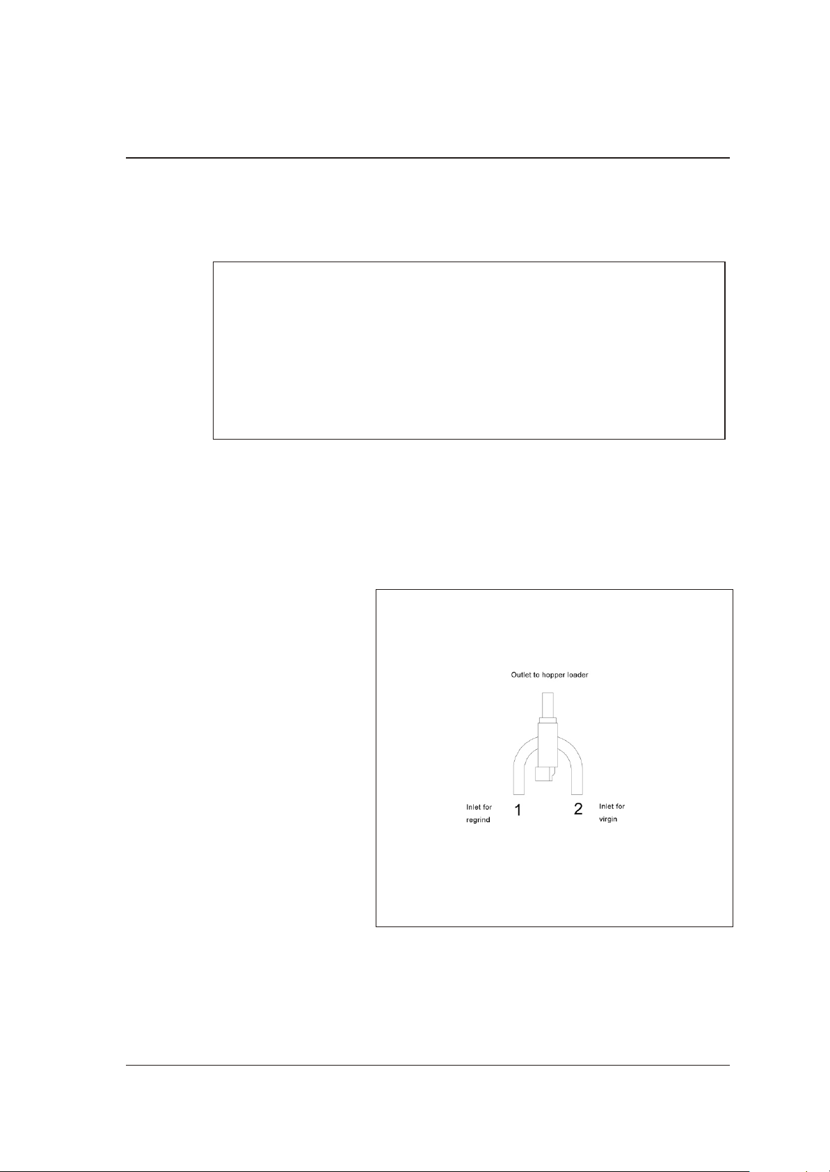
Remove the plugs from the
pipe bends.
Install the regrind line at intake
port 2 of the SKW.
Install the virgin material line
at intake port 1 of the SKW.
Install the feed line to the
hopper loader at the outlet port
of the SKW.
Align both suction pipes
equally in order to avoid
inaccurate percentage
preselection results.
Assembly SKW
046-3MS
In stal la ti on in struc tions 17
Page 18

2.2. Elec tri cal con nec ti on
2.2.1. Con nec ti on to a sing le con vey or unit CSE 2/CSE 5
Electrical connections are to be made by trained personnel
»
only.
Observe the regulations of your local Electricity Board.
All work is to be carried out with the equipment
disconnected from electric power and compressed air
supply.
SKW
The power consumption value of the SKW is approx. 15 Watts.
The operating voltage of the SKW is 100 V/60 Hz.
Special voltage on request.
Lay a cable (min. 3 x 1 mm2) from the single conveyor unit to the SKW.
Install the supplied plugs.
Install the plug of the SKW at the plug connector of the single conveyor control
unit.
Observe the operating instructions of the single conveyor unit.
046-3MS
In stal la ti on in struc tions 18
Page 19

2.2.2. Con nec ti on to a vac uum receiver unit SSK-05 1, 3, 5, & 30
Electrical connections are to be made by trained personnel
»
The power consumption value of the SKW is approx. 15 Watts.
The operating voltage of the SKW is 24 V.
only.
Observe the regulations of your local Electricity Board.
All work is to be carried out with the equipment
disconnected from electric power and compressed air
supply.
SKW
Lay a cable (min. 3 x 1 mm2) from the single conveyor unit to the SKW.
Install the supplied plugs.
Install the plug of the SKW at the plug connector of the single conveyor control
unit.
Observe the operating instructions of the vacuum receiver unit.
2.2.3. Con nec ti on to a con vey ing sys tem controller
The electrical connection to a conveying system controller
»
046-3MS
may only be made by skilled personnel authorized by
Sterling.
Other persons are not permitted to install electrical
connections.
In stal la ti on in struc tions 19
Page 20

2.3. Com pres sed air supp ly
For actuating the piston in the SKW
a compressed air supply
connection (1/4 inch) is required.
Check compressed air piping for
correct installation and assembly.
Check fittings, length and quality of
the hose connections for
agreement with requirements.
The operating pressure of the SKW
is 5-6 bar (72.52-87.02 PSI)
(system overpressure).
Check the compressed air supplied
by the plant’s supply network.
Adjust compressed air pressure to
5-6 bar(72.52-87.02 PSI) (system
overpressure).
SKW
Maintenance unit
Compressed air must be dewatered and oiled.
Install a maintenance unit (pressure reducer with water separator and oiler) if
required.
Connect the SKW to the plant’s supply network by means of a hose.
L
F
046-3MS
Depressurize compressed air supply lines which must be
opened.
Compressed air must be dewatered and oiled.
Adjust pressure to a max. value of 6 bar (87.02 PSI)
(system overpressure).
In stal la ti on in struc tions 20
Page 21

3. Functio nal des crip ti on
This functional description is intended for the operating
»
personnel of the equipment.
Prerequisite for this functional description is general
knowledge of conveyor systems operation.
Ensure in each case that the operating personnel are
sufficiently informed.
The SKW can only be operated in conjunction with a
conveyor unit.
F
SKW
046-3MS
Functio nal des crip ti on 21
Page 22

SKW
3.1. Ge ne ral in for ma ti on
The SKW has 2 elbows (virgin material intake port, regrind intake port) and an
outlet pipe socket leading to the conveyor unit.
With the SKW it is possible to convey two components to a hopper loader.
The SKW works in dependence on the conveying cycles of the conveyor unit. It is
only in operation when material is conveyed.
The SKW is available in 2 versions:
Version 1
·
Operation on SKW
SKW for connection to a single conveyor unit CSE 2/5;
Version 2
·
Operation on the conveying control
SKW for connection to a conveying control.
046-3MS
Functio nal des crip ti on 22
Page 23

SKW
3.2. Con trol
3.2.1. SKW Ver si on 1
The control unit is installed at the housing of the SKW.
The conveying ratio as well as the switching cycles are set by means of the keys
on the front side of the control system.
Per cen ta ge key Ar row key Dis play
SKW control system
046-3MS
Functio nal des crip ti on 23
Page 24

SKW
3.2.1.1. Con vey ing ra tio
The conveying ratio between component 1 (= regrind) and component 2 (= virgin
material) can be freely selected.
The control setting refers to the conveying time of component 1 (= regrind).
The conveying time of component 1 can be set from 0 to 99 % of total conveying
time.
Example
Proportioning valve setting: 22 %
Conveying ratio: 22 % component 1 and 78 % component 2
&
Conveying ratio relates to conveying time, not to the
amount of material conveyed.
046-3MS
Functio nal des crip ti on 24
Page 25

SKW
3.2.1.2. Swit ching cy cles
During each switching cycle, the SKW switches back and forth one time. The
pre-set conveying ratio is not affected by this. In order to prevent strong formation
of layers in the conveyed material, the number of switching cycles per conveying
procedure can be freely selected. Setting takes place by entry of one cycle
period. The cycle period can be set between 5 and 50 seconds. The setting is
carried out in five seconds.
The cycle period may not be longer than the conveying
time.
F
&
Example
Conveying time: 90 seconds, cycle period = 15 seconds
Calculation of switching cycles:
conveying time
cyc l e period
The shorter the cycle period, the higher the number of
switching cycles.
The higher the number of switching cycles, the less
significant is the zoning effect in the hopper loader.
s
switching cycles
Cycle period must always be high enough that both virgin
material and regrind are conveyed properly.
90
15
6 itching cycles
s
F
sw= =
046-3MS
Functio nal des crip ti on 25
Page 26

SKW
3.2.2. SKW Ver si on 2
On the SKW housing, a terminal box is installed (optional: terminal box with 3
light-emitting diodes = LEDs for limit position monitoring).
&
The conveying ratio and the switching cycles are entered into the control system
of the conveying control.
Observe the operating manual of the conveying control.
The two green LEDs indicate the limit positions of the
rotary piston. The red LED goes on in case of a
disturbance.
046-3MS
Functio nal des crip ti on 26
Page 27

4. Start-up
»
SKW
This chapter is intended for operating personnel.
Prerequisite for this chapter is general knowledge of the
operation of conveying units.
Also prerequisite for this chapter is that the functional
description has been read and understood.
Ensure in each case that the operating personnel are
sufficiently informed.
F
&
Check the compressed air supply (max. 6 bar system
overpressure). (87.02 PSI)
Check the connections of the conveying lines.
Check the suction pipe adjustment.
The SKW can only be operated in conjunction with a
conveying system.
046-3MS
Start-up 27
Page 28

4.1. Ad ju sting the con vey ing ra tio
Adjust the conveying ratio according to your specific requirements.
SKW Version 1
By means of the arrow key, set the percentage of
component 1 (= regrind).
Ex am ple
Desired conveying ratio: 40 % regrind and 60 % raw material.
Press the arrow key until “40" appears on the display.
When conveying poorly flowing components, set higher
values.
F
SKW
SKW Version 2
Set the percentage of component 1 (= regrind) by means of the control system of
the conveying control.
Observe the operating manual of the conveying control.
046-3MS
Start-up 28
Page 29

SKW
4.2. De ter mi ning the swit ching cy cle du ra ti on
Measure the conveying time of the respective hopper.
Take out the table.
Look for the value in the column “conveying time”.
Select a number of switching cycles.
Press the percentage key.
By means of the arrow key, select the desired switching cycle.
Carry through one conveying procedure.
If you are not satisfied with the result, check the setting and correct, if necessary.
No thick layers may form in the hopper loader.
F
Ex am ple
Conveying time: 50 s
Conveying ratio: 40 % regrind, 60 % virgin material
Setting options for a conveying time of 50 s:
Con vey ing
time
(se conds)
50
Num ber of swit ching cy cles at cy cle pe ri od (se conds)
50 45 40 35 30 25 20 15 10 5
1 1,1 1,3 1,4 1,7 2 2,5 3,3 5 10
046-3MS
a.) Setting 50 seconds = 1 switching cycle per conveying procedure
Start-up 29
Page 30

SKW
The SKW switches twice; it conveys
regrind for 20 seconds and virgin
material for 30 seconds.
Sig ni fi cant zo ning.
b.) Setting 10 = 5 switching cycles per
conveying procedure
The SKW switches ten times; it
conveys regrind for 4 seconds and
virgin material for 6 seconds.
In sig ni fi cant zo ning.
046-3MS
Start-up 30
Page 31

c.) Setting 5 = 10 switching cycles per conveying cycle
The SKW switches 20 times; it
conveys regrind for 2 seconds
and virgin material for 3 seconds.
This process is repeated 10
times.
No cor rect con vey an ce pos si ble.
With a conveying time of 2 to 3
seconds the material cannot be
conveyed properly.
SKW
046-3MS
Start-up 31
Page 32

4.3. Set ting the swit ching cy cles
SKW Ver si on 1
Press the percentage key.
By means of the arrow key, set the determined switching cycle.
Check the result.
If the result is not satisfactory, correct the setting.
SKW
&
SKW Version 2
Set the determined value by means of the control system of the conveying
control.
Observe the operating manual of the conveying control.
Check the result.
If the result is not satisfactory, correct the setting.
If there are too many switching cycles, proper conveying is
not possible.
046-3MS
Start-up 32
Page 33

5. Main ten an ce
This chapter is intended for persons with skills in electrical
»
and mechanical areas due to their training, experience and
received instructions.
Personnel using the instructions in this chapter must be
instructed of the regulations for the prevention of
accidents, the operating conditions and safety regulations
and their implementation.
SKW
Ensure in each case that the personnel are informed
accordingly.
For maintenance work taking place at heights of over
approx.1829 mm (6 ft), use only ladders or similar
equipment and working platforms intended for this
purpose. At greater heights, the proper equipment for
protection against falling must be worn.
Use only suitable lifting gear which is in proper working
order and load suspension devices with sufficient carrying
capacity. Do not stand or work under suspended loads!
Ensure that the electric motors/switch cabinets are
sufficiently protected against moisture.
Use only suitable workshop equipment.
Before starting maintenance work, appoint a supervisor.
Inform the responsible personnel before maintenance work
046-3MS
on the system is started.
Main ten an ce 33
Page 34

Never operate the equipment when partially dismantled.
All maintenance and repair work not described in this
chapter may only be carried out by Sterlingservice
personnel or authorized personnel (appointed by Sterling).
SKW
L
F
Disconnect the equipment from mains supply before
starting maintenance procedures to ensure that it cannot
be switched on unintentionally.
Depressurize all compressed air piping of the equipment
before starting maintenance work.
Please observe the maintenance intervals.
Before starting maintenance work, clean the equipment of
oil, fuel or lubricants.
Ensure that materials and incidentals required for
operation as well as spare parts are disposed of properly
and in an environmentally sound manner.
Use only original Sterling spare parts.
Keep record of all maintenance and repair procedures.
046-3MS
Main ten an ce 34
Page 35

SKW
5.1. Main ten an ce in ter vals
Dai ly: Check war ning signs on equip ment for good
le gi bi li ty and com ple te ness.
Check the oil le vel in the oi ler.
Emp ty the wa ter se pa ra tor.
Check ope ra ting pres su re of the plant’s supp ly
net work (5-6 bar (72.52-87.02 PSI) sys tem over
pres sure).
Every three months: Check the SKW for smooth ope ra ti on.
Every six months: Check all elec tri cal and me cha ni cal con nec tions
for se cu re fit.
F
In case of soiled material and material with a high dust
content equipment should be checked monthly for smooth
operation.
046-3MS
Main ten an ce 35
Page 36

5.2. Chec king for smooth ope ra ti on
Disconnect the equipment from mains power supply to
»
Unscrew the plug at the solenoid valve.
Remove the hose from the hopper loader
outlet port.
ensure that it cannot be switched on unintentionally.
In order to check for smooth operation compressed air
supply to the SKW must be maintained.
Danger! Limbs may be caught in machinery!
SKW
Move the manual actuator of the solenoid
valve from position B to position A and
back
Observe the piston through the pipe
socket at the “hopper loader outlet port”.
The piston must move back and forth
quickly.
Put the hose at the hopper loader outlet
port back in place.
Screw the plug to the solenoid valve.
046-3MS
6. Tech ni cal data
Tech ni cal data 36
Page 37

SKW
Ver sions: SKW 40
SKW 50
SKW 65
SKW 40
Height: 305 mm (12.01 in.)
Width: 246 mm (10.79 in.)
Depth: 235 mm (9.35 in.)
Weight: 7.5 kg (16.53 lbs.)
Com pres sed air supp ly: 5-6 bar (72.52-87.02 PSI) sys tem over pres su re
Pi ping sys tem: Æ 40 mm (1.67 in.)
SKW 50
Height: 305 mm (12.01 in.)
Width: 256 mm (10.18 in.)
Depth: 235 mm (9.35 in.)
Weight: 7.5 kg (16.53 lbs.)
Com pres sed air supp ly: 5-6 bar (72.52-87.02 PSI) sys tem over pres su re
Pi ping sys tem: Æ 50 mm ((2.07 in.)
SKW 65
Height: 340 mm (13.49 in.)
Width: 290 mm (11.42 in.)
Depth: 245 mm (10.7 in.)
Weight: 12.5 kg (27.66 lbs.)
Com pres sed air supp ly: 5-6 bar (72.52-87.02 PSI) sys tem over pres su re
Pi ping sys tem: Æ 65 mm (0.36 in.)
046-3MS
Tech ni cal data 37
Page 38
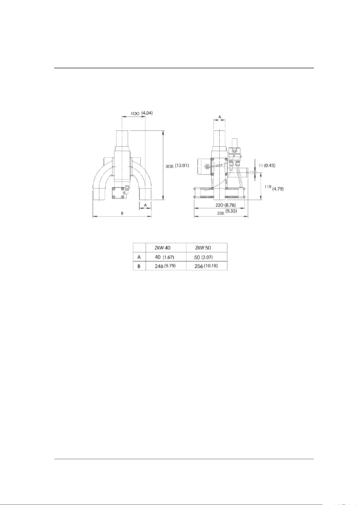
6.1. Di men si on sheet SKW 40/50
SKW
All di men sions in mm. (in.) Spec i fi ca tions may be sub ject to al te ra ti on.
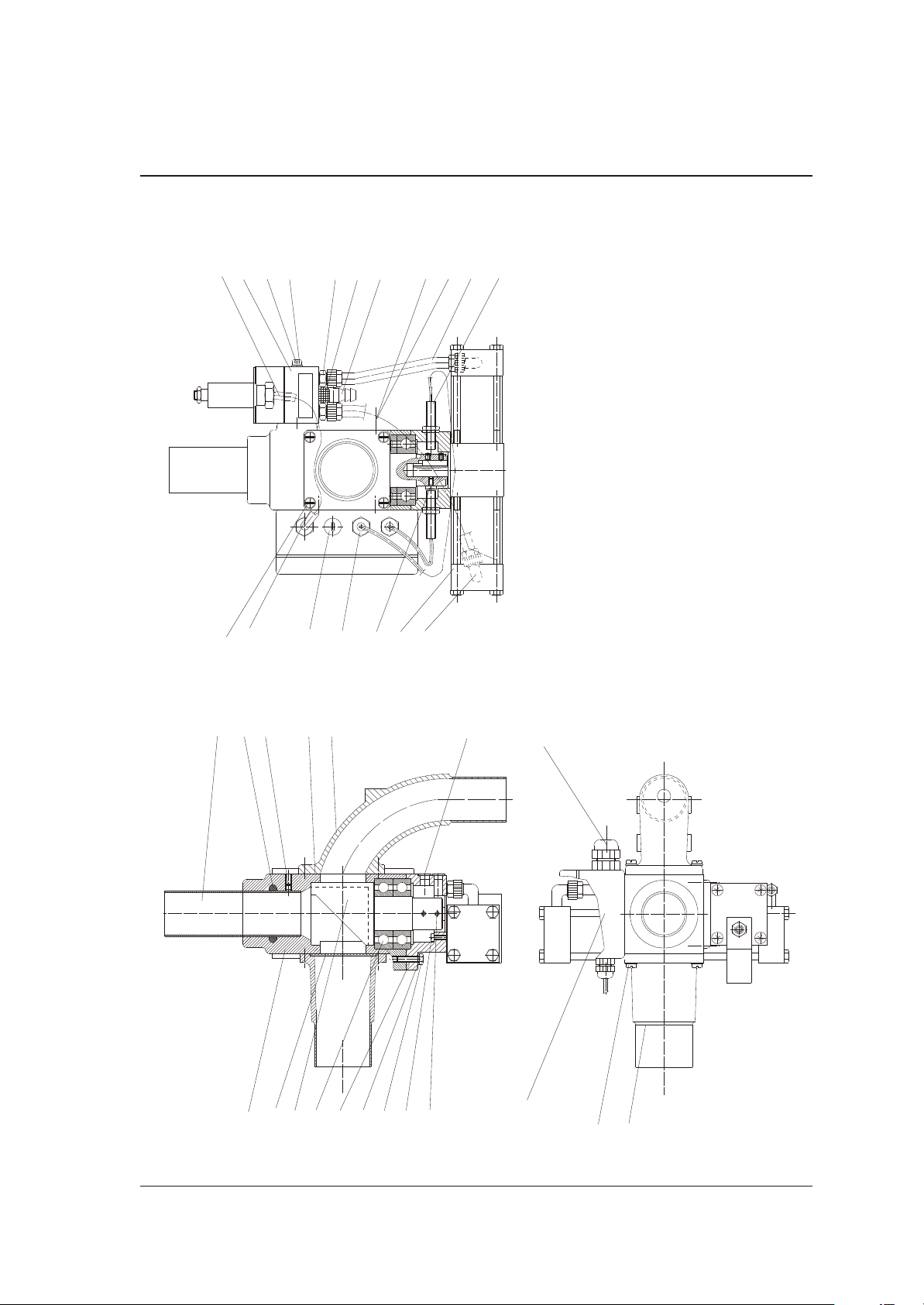
6.2. Di men sion sheet SKW 65
(On next page)
046-3MS
Tech ni cal data 38
Page 39

SKW
All di men sions in mm (in.). Spec i fi ca tions may be sub ject to al te ra ti on.
046-3MS
Tech ni cal data 39
Page 40

7. Ap pen dix
SKW
046-3MS
Ap pen dix 40
Page 41

7.1. Spa re parts list
This spare parts list is intended to be used only by trained
»
personnel.
Other persons are not permitted to modify or repair the
equipment.
SKW
046-3MS
Ap pen dix 41
Page 42

SKW 40 (03596)
5 - 6 bar
1
2
3
4
7
8
6
13
19
21
5
23
24
252212
26
27
28
9
11
10
14
18,31,32
15
16
20
5
6
33
17
SKW
046-3MS
Ap pen dix 42
Page 43

03596
Pos. Or der no. De sig na ti on
0001 03546 Hou sing
0002 03576 Pis ton
0003 96366 Deep groo ve ball bea ring
0004 03575 Bea ring lid
0005 95944 Spring lock was her
0006 95842 Screw
0007 96043 Screw
0008 95840 Threa ded pin
0009 97706 Pipe so cket
0010 96384 Sea ling ring
0011 95839 Threa ded pin
0012 98167 Hose nozzle
SKW
0014 03573 Bend
0015 27603 Sup port
0016 95841 Screw
0018 96045 Screw
0019 96373 Ro ta ry dri ve
0020 98753 Coup ling pie ce
0021 96372 So le noid val ve
0022 95985 Screw
0023 98752 Coup ling pie ce
0024 98742 Si len cer
0025 03604 Bow
0026 95844 Screw
0027 95956 Disc
0028 98750 Hose
0029 95556 Screw
0031 95948 Disc
046-3MS
0032 93882 Nut
0033 15475 Sea ling
Ap pen dix 43
Page 44

SKW
5 - 6 bar
1
2
3
4
7
8
6
13
18,31,32
15
16
19
17
21
5
23
24
252212
26
27
28
9
10
11
14
5
6
20
50
SKW 50 (03597)
046-3MS
Ap pen dix 44
Page 45

03597
Pos. Or der no. De sig na ti on
0001 03547 Hou sing
0002 03576 Pis ton
0003 96366 Deep groo ve ball bea ring
0004 03575 Bea ring lid
0005 95842 Screw
0007 96043 Screw
0008 95840 Threa ded pin
0009 97704 Pipe so cket
0010 96383 Sea ling ring
0011 95839 Threa ded pin
0012 98167 Hose nozzle
0013 95955 Disc
SKW
0014 03574 Bend
0015 27603 Sup port
0016 95841 Screw
0018 96045 Screw
0019 96373 Ro ta ry dri ve
0020 98753 Coup ling pie ce
0021 96372 So le noid val ve
0022 95985 Screw
0023 98752 Coup ling pie ce
0024 98742 Si len cer
0025 03604 Bow
0026 95844 Screw
0027 95956 Disc
0028 98750 Hose
0031 95948 Disc
0032 93882 Nut
046-3MS
0033 15476 Sea ling
Ap pen dix 45
Page 46

SKW 65 (12446)
5 - 6 bar
1
2
3
4
8
9
14
6
13
19
20
21
5
23
24
25
22
12
26
27
28
15
16
5
6
18,31,32
7
50
51
17
SKW
046-3MS
Ap pen dix 46
Page 47

12446
Pos. Or der no. De sig na ti on
0001 12416 Hou sing
0002 12418 Pis ton
0003 92226 Deep groo ve ball bea ring
0004 12417 Bea ring lid
0005 95944 Spring lock was her
0006 95842 Screw
0007 96043 Screw
0008 95840 Threa ded pin
0009 17208 Pipe so cket
0012 98167 Hose nozzle
0013 95955 Disc
0014 12414 Bend
SKW
0015 27603 Sup port
0016 95841 Screw
0017 99931 Ca ble
0018 96045 Screw
0019 96373 Ro ta ry dri ve
0020 98753 Coup ling pie ce
0021 96372 So le noid val ve
0022 95985 Screw
0023 98752 Coup ling pie ce
0024 98742 Si len cer
0025 03604 Bow
0026 95844 Screw
0027 95956 Disc
0028 98750 Hose
0031 95948 Disc
0032 93882 Nut
046-3MS
0050 15477 Sea ling
0051 88141 Sea ling
Ap pen dix 47
Page 48
SKW
5 - 6 bar
6
13
19
20
17
21
5
23
242212
26
27
28
1
2
3
4
5
6
7
8
9
11
10
14
29
35
36
37
39
38,40
42
41
33
34
50
CLV 40 (10102)
046-3MS
Ap pen dix 48
Page 49

10102
Pos. Or der no. De sig na ti on
0001 03546 Hou sing
0002 09518 Pis ton with fi nal switch po si ti on check
0003 96366 Deep groo ve ball bea ring
0004 09519 Bea ring lid with fi nal switch po si ti on check
0005 95944 Spring lock was her
0006 95842 Screw
0007 96043 Screw
0008 95840 Threa ded pin
0009 97706 Pipe so cket
0010 96384 Sea ling ring
0011 95839 Threa ded pin
0012 98167 Hose nozzle
SKW
0013 95957 Disc
0014 03573 Bend
0017 99931 Ca ble
0019 96373 Ro ta ry dri ve
0020 98753 Coup ling pie ce
0021 96372 So le noid val ve
0022 95985 Screw
0023 98752 Coup ling pie ce
0024 98742 Si len cer
0026 95844 Screw
0027 95956 Disc
0028 98750 Hose
0029 96038 Screw
0033 97763 Co ni cal caps
0034 92477 3-wire -in itia tor with LED
0035 88071 Screw
046-3MS
0036 11503 Nozzle
0037 93228 Sie ve
Ap pen dix 49
Page 50

0038 11122 Hou sing
0039 99944 Coup ling pie ce
0040 92470 SKW-MLV con trol card
0041 98609 Coup ling pie ce
0042 93075 Welsh plug
0050 15475 Sea ling
0051 85982 Dis tan ce bolt
0052 95946 Spring lock was her
0053 95970 Nut
SKW
046-3MS
Ap pen dix 50
Page 51

Con nec ti on dia gram
SKW
046-3MS
Ap pen dix 51
Page 52

Con vey ing
time
Num ber of swit ching cy cles at cy cle pe ri od (se conds)
(se conds)
5
10
15
20
25
30
35
40
45
50
55
60
65
50 45 40 35 30 25 20 15 10 5
* * * * * * * * * 1
* * * * * * * * 1 2
* * * * * * * 1 1,5 3
* * * * * * 1 1,3 2 4
* * * * * 1 1,3 1,7 2,5 5
* * * * 1 1,2 1,5 2 3 6
* * * 1 1,2 1,4 1,8 2,3 3,5 7
* * 1 1,1 1,3 1,6 2 2,7 4 8
* 1 1,1 1,3 1,5 1,8 2,3 3 4,5 9
1 1,1 1,3 1,4 1,7 2 2,5 3,3 5 10
1,1 1,2 1,4 1,6 1,8 2,2 2,8 3,7 5,5 11
1,2 1,3 1,5 1,7 2 2,4 3 4 6 12
1,3 1,4 1,6 1,9 2,2 2,6 3,3 4,3 6,5 13
70
75
80
85
90
95
100
105
110
115
120
* = Setting not permitted
1,4 1,5 1,8 2 2,3 2,8 3,5 4,7 7 14
1,5 1,7 1,9 2,1 2,5 3 3,8 5 7,5 15
1,6 1,8 2 2,3 2,7 3,2 4 5,3 8 16
1,7 1,9 2,1 2,4 2,8 3,4 4,3 5,7 8,5 17
1,8 2 2,3 2,6 3 3,6 4,5 6 9 18
1,9 2,1 2,4 2,7 3,2 3,8 4,8 6,3 9,5 19
2 2,2 2,5 2,9 3,3 4 5 6,7 10 20
2,1 2,3 2,6 3 3,5 4,2 5,3 7 10,5 21
2,2 2,4 2,8 3,1 3,7 4,4 5,5 7,3 11 22
2,3 2,6 2,9 3,3 3,8 4,6 5,8 7,7 11,5 23
2,4 2,7 3 3,4 4 4,8 6 8 12 24
 Loading...