

Page 1

1
CB-Funkgeräte AE 6490 / AE 6491
BEDIENUNGSANLEITUNG
Deutsch / English / Español
Deutsch
Page 2

2
Inhalt
Sicherheitshinweise ....................................................................................................... 3
Bedienelemente und Anschlüsse ............................................................................... 4
Frontansicht ................................................................................................................... 4
Rückseite ....................................................................................................................... 5
Mikrofon ......................................................................................................................... 5
Lieferumfang .................................................................................................................. 5
12 V / 24 V DC-Stromanschluss .................................................................................. 7
Montage mit DIN-Einschubhalterung ............................................................................. 7
Funkgerät aus der DIN-Halterung ausbauen ................................................................. 8
Bedienung .................................................................................................................... 9
Ein- und ausschalten ..................................................................................................... 9
Ländercodes (Unterstützung europäischer Multi-Standards) ......................................... 9
Ländercode einstellen .................................................................................................. 10
Reset auf Werkseinstellungen ..................................................................................... 10
Rauschsperre (SQ) und Funktionstaste (FC) ............................................................... 11
Funktionsumschalter (FC) ............................................................................................ 11
AM/FM Umschaltung ................................................................................................... 12
SCAN ........................................................................................................................... 12
Notrufkanal (EMG) ....................................................................................................... 13
Speicherkanäle (MEM)................................................................................................. 13
ASQ ............................................................................................................................. 13
Zweitbelegung der Tasten ......................................................................................... 14
MENU .......................................................................................................................... 14
MSCAN ........................................................................................................................ 15
SHIFT .......................................................................................................................... 15
MSAVE ........................................................................................................................ 16
LO / CT ........................................................................................................................ 16
Technische Spezifikationen AE 6490/ AE 6491 ........................................................ 17
Hinweise zur Entsorgung von Elektronikschrott ........................................................... 17
Gewährleistung / Werksgarantie und Servicehinweise .......................................... 18
Declaration of Conformity / Konformitätserklärung ...................................................... 20
Deutsch
Page 3

3
Wichtige Informationen
Bitte lesen Sie diese Hinweise vor Installation und Betrieb Ihres AE 6491
Funkgeräts aufmerksam durch.
Dieses Gerät ist ein hochentwickeltes mobiles CB-Funkgerät.
Das Schaltungskonzept verbindet neueste Schaltkreistechnologie mit einem
mikroprozessorgesteuerten Steuerungssystem.
Die Bedienung ist auf die wesentlichen Funktionen eines LKW und PKW EinbauFunkgeräts abgestimmt und erlaubt damit intuitiven Bedienungskomfort.
Das Gerät ist mit folgenden Standardfunktionen ausgestattet:
● PLL Frequenzerzeugung mit Mikroprozessor
● Großes Weitwinkeldisplay zur Multifunktionsanzeige (STN-Technologie)
● kräftiger Frontlautsprecher für problemlosen Armaturenbrett-Einbau
● Suchlauf (Scan) für alle Kanäle oder für gespeicherte Kanäle
● Speicher- und Aufruffunktion für bis zu 5 Kanäle
● automatische (ASQ) und signalabhängige Rauschsperre umschaltbar
● Tastensperre
● Sofortzugriff auf Kanal 9 oder 19
● AM/FM Umschaltung
● Separate Drehknöpfe für Kanal, Lautstärke und Rauschsperre
● Externe Lautsprecherbuchse (3,5 mm Mono) und Koaxial-Antennenbuchse (SO-239)
● DIN Abmessungen zum einfachen Einbau im Armaturenbrett über DIN –Halterung
● Hintergrundbeleuchtung 2 farbig umschaltbar, RX/TX Anzeige mit zweifarbiger LED
● Unterstützt alle europäischen CB-Funk Standards (außer der fest programmierten
Sonderausführung für Österreich auf Anfrage)
• AE 6490: 12V Bordnetzanschluss, AE 6491: 12 V / 24 V Bordnetzanschluss ohne
Umschalten möglich
Sicherheitshinweise
Fahrzeuge mit Airbags
• Montieren Sie Ihr Funkgerät nicht im Bereich über einem Airbag oder im
Entfaltungsbereich der Airbags.
• Airbags öffnen sich mit großer Kraft.
• Ist Ihr Funkgerät im Bereich eines Airbags montiert oder abgelegt und er
öffnet sich, so kann das Funkgerät mit großer Kraft durch die Luft
geschleudert werden und Verletzungen oder Sachschäden verursachen.
Potenzielle explosive Umgebungen
• Schalten Sie das Funkgerät an Tankstellen und in potenziell explosiven
Bereichen aus, denn jede auftretende elektrische Funkenentladung kann eine
gefährliche Situation herbeiführen.
Deutsch
Page 4

4
Umgebungen von Sprengungen
• Zur Vermeidung möglicher Störungen bei Sprengungen schalten Sie Ihr
Funkgerät in der Nähe von Sprengbereichen und in Bereichen aus, in den
entsprechende Hinweisschilder darauf hinweisen. Beachten Sie die
entsprechenden Schilder und Anleitungen.
Benutzung während der Fahrt
• Informieren Sie sich Sie sich über die regional unterschiedlichen CB
Bestimmungen und beachten Sie diese.
• In einigen europäischen Ländern ist es dem Fahrer verboten, während der
Fahrt ein Mikrofon zu halten oder ein Funkgerät zu bedienen.
• Einige Länder (wie Deutschland) machen einen Unterschied zwischen
Handys und Funkgeräten. Handys dürfen nur mit Freisprechanlage betrieben
werden, während CB- und gewerbliche Funkgeräte selbst mit Handmikrofon
weiterhin erlaubt sind.
Bedienelemente und Anschlüsse
Frontansicht
1 Ein-/Ausschalter und Lautstärkeregler
2 LCD-Display
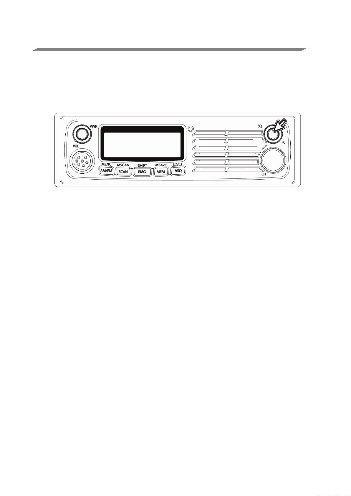
3 Rauschsperre
4 Funktionsumschalter mit Tastendruck
5 Mikrofonbuchse
6 AM/FM (Menü)
7 SCAN, MSCAN (Speicherscan)
8 EMG (Notrufkanal 9), SHIFT für zweiten EMG-Kanal (CH 19)
9 MEM (Speicheraufruf), MSAVE (Speicherung)
10 ASQ (Automatische Rauschsperre), LO (Tastensperre) oder CT (CTCSS-Ton )
11 Kanal-Drehknopf
Deutsch
Page 5

5
Rückseite
1 Antennenbuchse mit PL 259 Koaxialanschluss
2 Externe Lautsprecherbuchse (für 3,5 mm Mono-Klinke)
3 DC-Stromkabel 12 V bzw. 12 V/ 24V je nach Version
Mikrofon
1 Sprechtaste (PTT)
2 Aufwärtstaste
3 Abwärtstaste
4 ASQ ein/aus
Lieferumfang
● 1 x AE 6490 bzw. AE 6491 CB-Funkgerät
● 1 x Handmikrofon
● 1 x DC-Stromkabel mit Inline-Sicherung
● 1 x Standard Montagehalterung mit Montageschrauben
● 1 x Mikrofonhalterung
● 1 x DIN-Montagesatz (1 DIN- Einbaurahmen und 2 Ausbauschlüssel)
● 1 x Bedienungsanleitung
Vorsicht
Bei der Installation Ihres Funkgeräts im Fahrzeug vergewissern Sie sich, dass Sie
keine Verkabelung oder sonstige Fahrzeugkomponenten beschädigen, die sich
möglicherweise versteckt im Bereich der Montageposition befinden. Sind Sie sich nicht
ganz sicher, wie Ihr CB Gerät eingebaut werden muss, so wenden Sie sich bitte an
einen Autoradiodienst oder den Fahrzeughersteller.
Deutsch
Page 6

6
Installation der Antenne
SWR-Informationen zur Antenne
Energieverluste bei der Übertragung und Schäden am Sender (insbesondere
Kabel an die Antenne weitergeleitet wird und dass der reflektierte Wert gering
Messung ist einfach und ein guter Gradmesser für die korrekte
Für beste Leistung Ihres CB Funkgeräts ist die Installation einer hochwertigen Antenne
von großer Bedeutung.
• Kaufen Sie eine geeignete mobile Antenne für das 27-MHz-Frequenzband.
• Schließen Sie die Antenne an der Antennenbuchse auf der Geräterückseite mit
einem PL259 Koaxialstecker an. Nötigenfalls löten Sie den Stecker vorsichtig an
die innere Litze des Koaxialkabels. Vermeiden Sie jeglichen Kurzschluss mit
einem der dünnen Kupferdrähte der äußeren Koaxialabschirmung.
• Für beste Leistung des Funkgeräts montieren Sie die Antenne an geeigneter
Stelle für gute und freie Abstrahlung von der metallischen Fahrzeugoberfläche.
• Standard-Mobilantennen benötigen eine gute Fahrzeugmasse für besten Betrieb.
Die meisten Standard-Mobilantennen funktionieren nicht ohne eine gut leitende
Verbindung zur Fahrzeugmasse!
• Die meisten CB-Antennen (außer unserer Baureihe „Gamma“) benötigen eine
Feinabstimmung für bestes SWR.
• Spezielle erdungsfreie Antennen erhalten Sie für Camper oder LKW für den Fall,
dass die Fahrzeugteile um die Antennenposition aus Kunststoff oder Glasfaser
sind oder wenn ein Masseanschluss nicht möglich ist. Solche Antennen arbeiten
nur auf Glasfaser- oder Kunststoffaufbauten und nicht unmittelbar auf
metallischen Strukturen.
• Benutzen Sie die Sendetaste (PTT) nicht, bevor Sie die Antenne installiert und
angeschlossen haben.
Zum Sendebetrieb muss eine Antenne gut abgestimmt sein, um
der Senderendstufe) zu vermeiden.
Eine gute Antenne erreicht ein SWR (Stehwellenverhältnis) von 1,5 oder
besser.
Dies bedeutet, dass der Großteil der Sendeleistung korrekt vom Sender über
ist.
Die SWRInstallation. Ein SWR-Meter ist ein grundlegendes und preiswertes Testgerät,
das in die Werkzeugtasche jedes Installateurs und Radio-/Funkspezialisten
gehört.
Hohe SWR-Werte (über SWR = 3,0) können nicht nur das Funkgerät
beschädigen, sondern führen ebenfalls zu Störproblemen mit anderen
elektronischen Geräten.
Deutsch
Page 7

7
12 V / 24 V DC-Stromanschluss
Während die Standardversion AE 6490 nur für 12 V (Anschlusswerte können variieren
von 10,8 V bis 15,6 V) konzipiert ist, erlaubt die 24 V Version AE 6491 den höheren
Spannungsbereich 12 und 24 V auch in LKW und Booten mit 24 V Bordnetz ohne
Umschalten (mit Minuspol an Karosserie). Die 24 V Spannung kann dabei bis 28 V
variieren. Die Bordspannung wird automatisch erkannt.
DC-Verkabelung
• Schließen Sie das negative (schwarze) DC-Stromkabel am Fahrzeugchassis
oder direkt am Minuspol der Fahrzeugbatterie an.
• Schließen Sie das positive (rote) DC-Stromkabel über die Im Kabel eingebaute
Sicherung an geeigneter Stelle im Sicherungskasten des Fahrzeugs oder direkt
am Pluspol der Fahrzeugbatterie an.
• Es ist außerdem möglich, das Funkgerät am über die Zündung geschalteten
Fahrzeug- Bordnetz anzuschließen, um eine automatisches Ein-
/Ausschalten über das Zündschloss zu ermöglichen, da das Funkgerät die
jeweils letzten Einstellungen speichert.
• In einigen Fällen kann es notwendig sein, ein (optionales) Entstörfilter gegen
Störungen der Lichtmaschine zu benutzen. Das hängt von der Position im
elektrischen System des Fahrzeugs ab, an welcher Sie das Funkgerät mit
+ und – angeschlossen haben. Kommt es zu Schwierigkeiten, so empfehlen
wir, andere Anschlusspunkte für den Stromanschluss ebenfalls zu testen.
Montage mit DIN-Einschubhalterung
Sind Sie sich nicht ganz sicher, wie Ihr CB Gerät im Fahrzeug mit der DIN-Halterung
eingebaut wird, so setzen Sie sich bitte mit dem Fahrzeughersteller, Ihrem
Fachhändler oder einem qualifizierten Installationsbetrieb in Verbindung.
Vor der Installation vergewissern Sie sich, dass das Funkgerät in den Einbaubereich
passt und dass Sie alle notwendigen Installationsmaterialien zur Hand haben.
Das Funkgerät kann auch mit dem herkömmlichen Montagebügel in Fahrzeugen
eingebaut werden.
• Vor dem Einsetzen des Funkgeräts in die Halterung verlegen Sie das Kabel
der zuvor montierten Antenne.
• Schließen Sie die DC-Stromkabel an. Das rote Kabel geht zu einer positiven
(+) Klemme in Ihrem Sicherungskasten, das schwarze Kabel an die
Fahrzeugmasse (-). Oft liegen bei LKW die Kabel schon vorbereitet im
Armaturenbrettausschnitt.
Deutsch
Page 8

8
Installation der DIN-Einschubhalterung
• Achten Sie darauf, dass die Verkabelung nicht durch Metallteile eingeklemmt
oder eingeschnitten wird.
• Schieben Sie das Funkgerät vorsichtig in die Halterung, bis es einrastet.
• Der Gummiring stellt die Abschlussdichtung gegen die DIN-Halterung dar.
Links und rechts vom Ring befindet sich je ein Schlitz zum vorsichtigen Ziehen
der linken und rechten Seite des Ringes.
• Die Schlitze im montierten Gummiring ermöglichen jederzeit den korrekten
Ausbau des Funkgeräts aus der DIN-Halterung.
Funkgerät in Armaturenbrett (DIN Schacht) einsetzen
Funkgerät aus der DIN-Halterung ausbauen
Möchten Sie das Funkgerät aus der DIN-Halterung ausbauen, so benutzen Sie hierzu
die beiden mitgelieferten Ausbau-Schlüssel wie folgt:
• Setzen Sie die beiden Schlüssel gerade in die Schlitze im Gummiring links
und rechts von der Blende des Funkgeräts ein.
• Das Funkgerät kann nicht mit nur einem Schlüssel ausgebaut werden.
• Drücken Sie die Schlüssel ganz ein, damit wird das Funkgerät entsperrt und
kann aus der Einschubhalterung herausgezogen werden.
• Bewahren Sie die Schlüssel sorgfältig für späteren Gebrauch auf.
Deutsch
Page 9

9
Bedienung
Ein- und ausschalten
Drehen Sie den Lautstärke-Drehregler zum Einschalten und zum Einstellen der
Lautstärke nach rechts.
Ländercodes (Unterstützung europäischer Multi-Standards)
Beide Versionen unterstützen die aktuellen Multi-Standards
In Österreich ist die Benutzung von Funkgeräten, die über eine Länderumschaltung
verfügen, grundsätzlich verboten. Eine spezielle Österreich-Version, bei der die
Umschaltung technisch nicht möglich ist, gibt es auf Anfrage als reine FM Version
(diese Anleitung gilt sinngemäß auch für dieses Modell).
Deutsch
Page 10

10
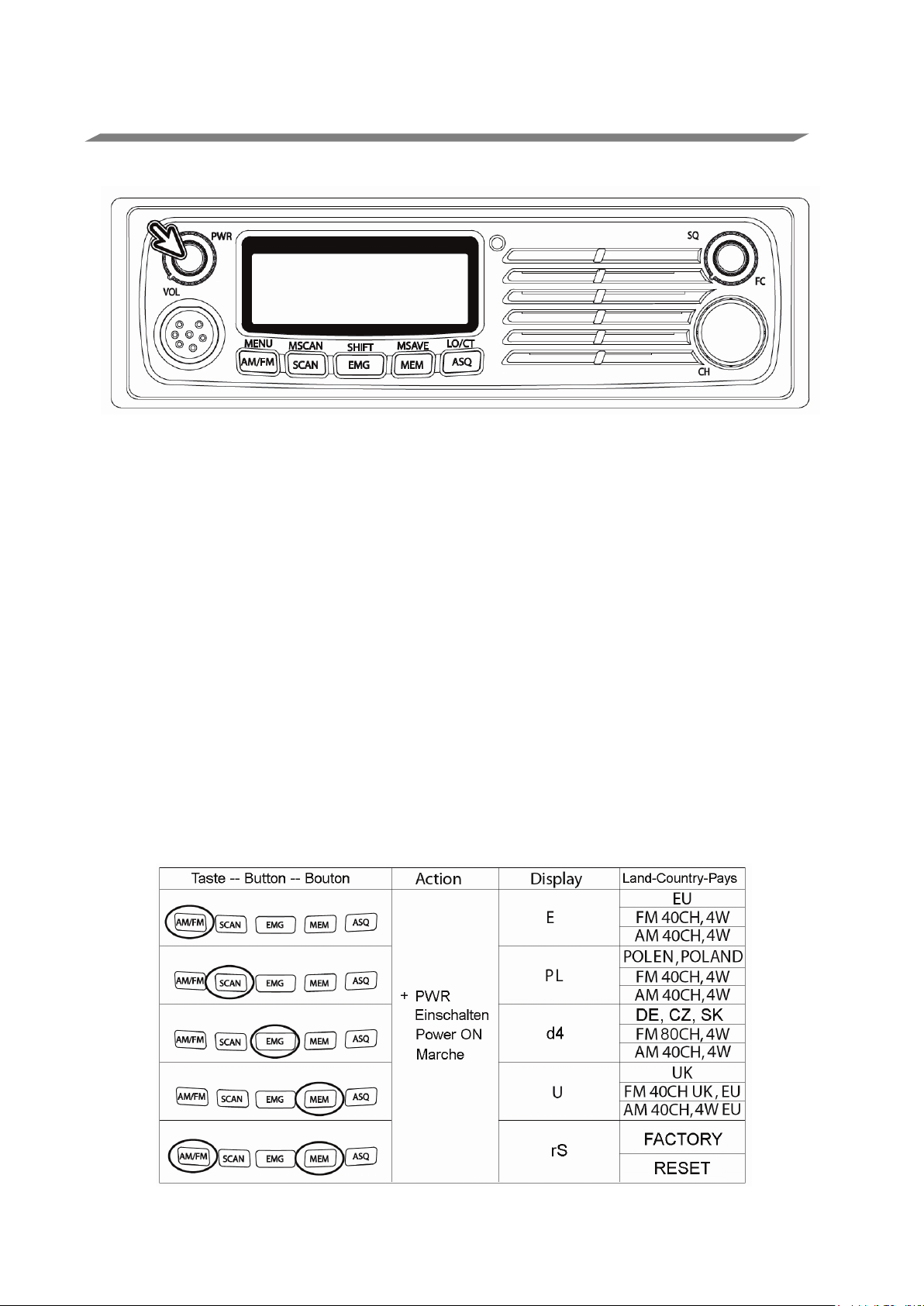
Ländercode einstellen
• Schalten Sie das Gerät ein und halten Sie gleichzeitig die Taste für das
entsprechende Land entspr. der Tabelle gedrückt.
• Dann lassen Sie die Taste(n) wieder los.
Die deutsche Einstellung d4 ist auch in CZ und SK erlaubt. Achten Sie aber darauf,
dass Sie in der Tschechischen Republik nur die 80 FM Kanäle benutzen (kein AM) und
in der Slowakei nur die internationalen Kanäle 1 bis 40 und die deutschen Kanäle 7080, ebenfalls ist dort nur FM gestattet.
Reset auf Werkseinstellungen
Die letzte Tastenkombination (Reset) wird zur Rückstellung zu den Werkseinstellungen
benutzt. Dies ist hilfreich, wenn das Funkgerät sich nicht normal bedienen lässt.
Eine Rückstellung stellt die Funktionen wieder her, falls der Prozessor einmal „hängt“.
Deutsch
Page 11

11
Rauschsperre (SQ) und Funktionstaste (FC)
• Mit dem Rauschsperrenregler unterdrücken Sie Hintergrundgeräusche, wenn
kein Signal anliegt.
• Mit Rechtsdrehung schalten Sie den Empfänger stumm, wenn keine Signale
empfangen werden und ermöglichen damit einen leisen Stand-by-Betrieb.
• Die Rauschsperre arbeitet nur im Empfangsmodus und hat keinen Einfluss auf
die Empfangslautstärke, wenn Signale empfangen werden.
• Zum Einstellen, wenn keine Signale anliegen, drehen Sie die Rauschsperre
vorsichtig soweit nach rechts, bis der Empfänger gerade stummgeschaltet ist.
• Eingehende Signale öffnen jetzt die Rauschsperre automatisch. Eine sorgfältige
Reglereinstellung ist notwendig, da eine Einstellung zu weit nach rechts dazu
führen kann, dass die Rauschsperre durch schwache Signale nicht mehr
geöffnet wird.
• Benutzen Sie die Scanfunktion, so ist eine Feinabstimmung besonders wichtig.
Der Scanner startet nur, wenn die Rauschsperre geschlossen ist und stoppt nur
bei einem ausreichend starken Signal.
Die Standard-Rauschsperre (Regler SQ) dieses Funkgeräts wird durch die Feldstärke
(also die Signalstärke) aktiviert. Das bedeutet, dass Sie mit der Einstellung des
Drehknopfes entscheiden, bei welcher Feldstärke (S-Meter-Wert) die Rauschsperre
öffnet.
Ein vollständig geschlossenes Rauschsperren-Potentiometer unterdrückt Signale bis
zu einigen Hundert Mikrovolt Eingangspegel. In der empfindlichsten Position öffnet die
Rauschsperre bei Signalen von weniger als 1 Mikrovolt.
Sie können ebenfalls die automatische Rauschsperre ASQ benutzen. Diese arbeitet
völlig anders als die signalstärkeabhängige Rauschsperre. ASQ kümmert sich nicht um
die Signalstärke, sondern reagiert, wenn das Rauschen auf einem Signal reduziert wird
und das Signal verständlich wird.
Funktionsumschalter (FC)
Der Regler für die Rauschsperre hat eine wichtige zweite Funktion, wenn dieser Knopf
gedrückt wird.
• Drücken Sie den Knopf für die Rauschsperre (SQ) kurz, so aktivieren Sie die
Zweitbelegung der Tasten, deren Funktion oberhalb der Tasten aufgedruckt ist.
Deutsch
Page 12

12
AM/FM Umschaltung
Mit AM/FM schalten Sie zwischen AM- und FM- Modulation um. Bitte beachten Sie,
dass bei der deutschen Ländereinstellung es möglich ist, auch auf den Kanälen 41-80
in AM zu empfangen, aber Sie können auf diesen Kanälen in AM nicht senden,
sondern nur auf Kanal 1-40. Die Balkenanzeige im Display zeigt bei Empfang die
Signalstärke ( S-Werte) und bei Senden die relative Sendeleistung zur Kontrolle an.
SCAN
Ihr Funkgerät ist mit einer Suchlauf (Scan) - Funktion ausgestattet. Das Funkgerät
scannt durch alle 40 (80) Kanäle und stoppt beim nächsten aktiven Kanal (d.h. da, wo
gerade ein Funkgespräch läuft). Der Kanal bleibt bis sieben Sekunden nach
Beendigung des Gesprächs eingestellt, dann wird weiter gescannt.
• Um den Scan zu starten, schalten Sie das Gerät zunächst ein und stellen Sie
Lautstärke und Rauschsperre ein.
• Mit SCAN starten Sie den Scan. SC wird im LCD angezeigt.
• Das Gerät startet den Suchlauf, den Sie im Display verfolgen.
• Zur Unterbrechung des Scans drücken Sie erneut die Scantaste oder die
Sprechtaste.
Hiermit wird die Scanfunktion beendet und sie können auf dem Kanal, auf dem der
Suchlauf gerade angehalten wurde, auch senden.
Deutsch
Page 13

13
Notrufkanal (EMG)
EMG (Emergency) dient dem sofortigen Aufrufen des internationalen Notrufkanals 9,
der von allen Fernfahrern und vielen CB-Funkern, in einigen Gebieten auch von
Hilfsorganisationen überwacht wird. Für Hilfe oder Beistand ist es eine gute Idee, einen
Notruf über Kanal 9 abzusetzen. Fernfahrer können in den meisten Fällen im AMModus erreicht werden.
• Sie erreichen Kanal 9 durch Druck auf EMG und schalten damit auch wieder auf
ihren vorher benutzten Kanal zurück.
Der Notrufkanal wird neuerdings auf deutschen Autobahnen als Warnsystem bei
Unfällen, Baustellen oder größeren Verkehrsstaus mit Kollisionsgefahr benutzt. Dazu
installieren die Autobahnmeistereien jetzt vermehrt Sensoren vor Baustellen oder
Sperrungen. Kommen Sie dort vorbei und auf Ihrer Spur vor Ihnen befindet sich eine
gefährliche Situation, so werden Sie mit Alarmtönen und Ansagen gewarnt.
Der andere, häufig benutzte Rufkanal ist Kanal 19, siehe Seite
Speicherkanäle (MEM)
Zum Aufrufen gespeicherter Kanäle drücken Sie einfach MEM und wählen Sie dann
den gewünschten Speicherkanal von M1 bis M5, indem Sie eine der Tasten AM/FM bis
ASQ drücken.
ASQ
Wie bereits zuvor im Kapitel Rauschsperre erwähnt, ist ASQ eine Automatik, die den
Empfang von Signalen ermöglicht, die weniger Rauschen aufweisen als das jeweilige
Grundgeräusch auf dem Kanal. Diese automatische Umschaltfunktion muss nicht
eingestellt werden und arbeitet vollautomatisch. Sie öffnet bei jedem Signal, das stark
genug ist, verstanden zu werden.
Die Empfindlichkeit des ASQ-Systems ist sehr gut. Es kann selbst bei Signalstärken
unterhalb der nutzbaren maximalen Soll-Empfindlichkeit öffnen. Das einzige Kriterium
ist die Reduzierung von Störungen auf dem Empfangskanal.
Die ASQ-Funktion ist jedoch auf normale Empfangsbedingungen im CB-Band
beschränkt.
Während starker Überreichweiten, starker Sonnenfleckenaktivität und bei sehr starken
Störsignalen kann die Funktion von Zeit zu Zeit öffnen, ohne dass ein Sprachsignal
gehört wird. In solchen Fällen ist es möglicherweise angebracht, die Standard-
Rauschsperre anstatt ASQ zu benutzen. Eine zusätzliche ASQ-Taste befindet sich auf
dem Mikrofon!
Deutsch
Page 14

14
Zweitbelegung der Tasten
MENU
Mit der Taste MENU durchlaufen Sie vier
UNTERMENÜS nacheinander.
MENU ist eine Zweitbelegung wie alle
anderen Funktionen, die in diesem
Kapitel beschrieben werden.
• Drücken Sie zunächst den
Funktionsumschalter FC
(Rauschsperre).
• Im Display wird FC angezeigt.
• Drücken Sie nun MENU (AM/FM).
Hier steuern Sie:
• Tastenton ein/aus;
• Roger Beep (Bestätigungston) ein/aus;
• Auswahl der Farbe der LCD-Hintergrundbeleuchtung;
• LCD-Hintergrundbeleuchtung (dunkler und heller).
Die Auswahl treffen Sie mit den Tasten AUFWÄRTS oder ABWÄRTS auf dem
Mikrofon oder durch Drehen des Kanalwahl-Drehknopfes.
• Drücken Sie einmal oder mehrmals MENU, um Ihre Auswahl zu speichern und
um das nächste Untermenü aufzurufen.
Beep on/off – Hier aktivieren/deaktivieren Sie den Tastenton.
Roger Beep ist der kurze Signalton am Ende jeder Übertragung, nachdem die
Sendetaste PTT auf dem Mikrofon losgelassen wird
Roger Beep on/off
Deutsch
Page 15

15
Farbe der LCD-Hintergrundbeleuchtung zwischen grün und rot umschalten.
LCD-Helligkeit einstellen (dunkler → heller).
MSCAN
Der Speicherkanal-Scan ermöglicht dem Funkgerät
den automatischen Scan durch 5 gespeicherte
Kanäle.
• Mit FC und MSCAN rufen Sie die Funktion
auf.
• M-SC wird im LCD angezeigt.
Das Funkgerät scannt nun automatisch nur die gespeicherten Kanäle und stoppt, wenn
Funkverkehr erkannt wird.
Bitte beachten Sie: Programmieren Sie Kanäle Ihrer Wahl als Speicherkanäle!
Einzelheiten siehe Kapitel MS AVE auf der nächsten Seite.
SHIFT
Kanal 19 hat sich in einigen Ländern außerhalb
Deutschlands zu einem Fernfahrerkanal etabliert.
Mit FC + SHIFT schalten Sie direkt zwischen
diesem Fernfahrer-Anrufkanal und Ihrem vorher
benutztem Kanal hin und her.
Deutsch
Page 16

16
MSAVE
MSAVE dient der Speicherung von Kanälen unter
den Speicherstellen M1 bis M5.
Zum Speichern von Kanälen gehen Sie wie folgt vor:
• Wählen Sie den gewünschten Kanal mit dem
Drehregler oder AUFWÄRTS/ABWÄRTS.
• Drücken Sie FC und dann MSAVE / MEM.
• Wählen Sie eine Speicherkanalnummer mit den Tasten MENU (M1) bis LO / CT
(M5).
LO / CT
Tastensperre
Mit der Tastensperre sperren Sie alle Tasten des
Funkgeräts, die nun nicht mehr versehentlich
gedrückt werden können.
• Drücken Sie FC und dann LO / CT.
Auf gleiche Weise entsperren Sie die Tasten wieder.
Bitte beachten Sie: Haben Sie eine Version mit CTCSS- Platine erworben, dann steht
Ihnen die Tastensperrfunktion nicht zur Verfügung.
CT (Toncodierte CTCSS Rauschunterdrückung) – optional (andere Version)
Dies ist eine optionale Funktion nur bei Geräten mit installiertem CTCSS- Tonmodul.
Ihnen stehen 38 CTCSS (Continuous Tone Coded Squelch System) Codierfunktionen
zu Verfügung, wenn Sie die Funkgeräte-Version mit dem 38-Töne CTCSS Modul
erwerben.
Die CTCSS- Platine ermöglicht Ihnen die Erstellung einer geschlosseneren
Benutzergruppe innerhalb des CB-Bandes und sie verhindert das Öffnen der
Rauschsperre durch andere Sender. Nur Sender mit dem korrekten CTCSS-Code auf
ihrer Übertragung können gehört werden.
Deutsch
Page 17

17
Technische Spezifikationen AE 6490/ AE 6491
SENDER
Quarzgesteuerter PLL-Synthesizer
EMPFÄNGER
Doppelsuper
SPANNUNGSVERSORGUNG
AE 6490 DC 10..16 V / AE 6491 DC 10..28V
(Nennspannungen 12 bzw. 12/24 V)
TEMPERATURBEREICH
-10 ˚C bis +55 ˚C
KANALSCHRITT
10 kHz
ABMESSUNGEN
188 (B) X 57 (H) X 158 (T) mm
GEWICHT
1,9 kg mit Standardzubehör
3,5 mm EXTERNE LAUTSPRECHERBUCHSE
Mono
UHF TYP (PL) ANTENNENBUCHSE
SO 239 (50-Ohm-Buchse für PL 259 Stecker)
KONDENSATORMIKROFON UND 6-PINANSCHLUSS
Entspricht Albrecht- und GDCH 6-Pin
Standardverkabelung außer PIN 4
FREQUENZBEREICH
26,965-27,405 MHz
FREQUENZTOLERANZ
+/- 100 Hz
MODULATIONSEMPFINDLICHKEIT
2,5 mV (1250 Hz Eingang)
MODULATIONSFÄHIGKEIT
AM 85 % / FM 2,0 kHz
20 dB)
RAUSCHSPERRE schließen
Bis zu 1000 µV
AUTOM. RAUSCHSPERRE
0,5 µV
RAUSCHABSTAND
40 dB
KLIRRFAKTOR
3 %
S-METER EMPFINDLICHKEIT S9
100 µV
AUDIO AUSGANGSLEISTUNG
Minimum 4 Watt bei 8 Ohm
SPANNUNGSVERSORGUNG
AE 6490: 12 V / AE 6491: 12V oder 24V DC
ANTENNE LASTIMPEDANZ
50 Ohm
AUDIO LASTIMPEDANZ
8 Ohm Impedanz, 4 Ohm möglich
Allgemein
Sender
AUSGANGSLEISTUNG
Empfänger
EMPFINDLICHKEIT AM: 0,5 µV (SINAD 10 dB), FM: 0,5 µV (SINAD
FM/AM 4 Watt
Anschlussbedingungen
Hinweise zur Entsorgung von Elektronikschrott
Die neue europäische WEEE Direktive regelt das Entsorgen und das
Recycling von Elektro- und Elektronikschrott. Damit das von der Industrie
finanzierte Entsorgungssystem funktioniert, sollten Sie- wenn einmal Ihr
Funkgerät entsorgt werden sollte (was wir nicht hoffen wollen!)- Ihr Gerät
nicht in die Haushaltsmülltonne werfen, sondern bei den kommunalen
Sammelstellen abgeben. Dort stehen Container für kostenlose Abgabe
bereit!
Das Zeichen mit der durchgestrichenen Mülltonne auf dem Typenschild soll Sie daran
erinnern!
Deutsch
Page 18

18
Gewährleistung / Werksgarantie und Servicehinweise
Entsprechend den europäischen Gewährleistungsregeln gewährt der Verkäufer Ihnen
auf ein neues Gerät zwei Jahre gesetzliche Gewährleistung. Falls ein Fehler bei Ihrem
Gerät auftreten sollte, wenden Sie sich bitte an den Fachhändler und zeigen Sie ggf.
Ihre Kaufquittung als Kaufnachweis vor. Ihr Händler wird den Fehler entweder vor Ort
beheben, oder das Gerät an eine von uns autorisierte Servicestelle weiterleiten. Sie
erleichtern unseren Technikern Ihre Arbeit sehr, wenn Sie evtl. Fehler ausführlich
beschreiben – nur dann haben Sie Gewähr, dass auch selten auftretende Fehler mit
Sicherheit gefunden und beseitigt werden!
Ist Ihr Fachhändler nicht erreichbar, senden Sie Ihr Gerät bitte direkt an eine der unter
www.hobbyradio.de angegebenen Serviceadressen. Vergessen Sie nicht, beim
Einsenden Ihre Kaufquittung (oder eine Kopie davon) beizufügen.
• Für in Deutschland verkaufte Geräte dieses Heavy Duty Funkgeräts leistet
Alan Electronics GmbH eine dreijährige Werksgarantie!
Unsere Empfehlung für den Fall eines technischen Problems:
a) Führen Sie einen Reset-Vorgang durch.
• Trennen Sie dazu das Gerät für ca. 10 sec. vom Stromnetz.
• Halten Sie AM/FM und MEM gedrückt und schalten Sie gleichzeitig das
Funkgerät wieder ein.
• Das Display zeigt kurzzeitig rS und dann wieder den normalen Betrieb an.
• In den meisten Fällen funktioniert ein Gerät nach einem Reset wieder wie
gewohnt – ggf. geben Sie auch den Ländercode neu ein.
Lässt sich eine Fehlfunktion auch durch einen Reset-Vorgang nicht beheben, rufen Sie
am besten zuerst unsere Hotline an. Die Erfahrung hat gezeigt, dass die meisten
Probleme in einem Telefongespräch bereits geklärt werden können. Außerdem können
unsere Servicemitarbeiter Ihnen dabei auch ggf. die für Sie nächste Serviceanschrift
durchgeben oder einen Reparaturtermin gleich vorreservieren.
Alan Electronics GmbH – Daimlerstr. 1 k D - 63303 Dreieich
Technische Anfragen und mögliche Reparaturen:
E-Mail: service@alan-electronics.de
Reparaturen, Ersatzteile: 06103 9481-22
(reguläre Kosten für das deutsche Festnetz)
Homepage: www.alan-electronics.de / www.albrecht-online.de
Service-Download service.alan-electronics.de
© Alan Electronics GmbH Mai 2014
Deutsch
Page 19

19
CB Bestimmungen, Gerätepass und CE Deklaration
Land
80/40
40/40
40 FM
Bemerkungen
Basisstationen in der Nähe der Grenzen (außer CZ)
Kanälen 41-80.
Besucher frei.
Österreich-Version des Gerätes.
Im FM Betrieb sind nur die Kanäle 1-40 und 70-80
erlaubt.
Anmeldung und regelmäßige Gebührenzahlung für
Einwohner erforderlich. Ausländische Besucher frei.
Albrecht Radio Passport
Für Ihr AE 6490/ AE6491 gelten folgende Programmierungs- und Benutzungsregeln (Angaben ohne
Gewähr, Stand Mai 2014) in den Ländern, die die Europäische R&TTE Direktive anwenden:
Belgien
Bulgarien
Dänemark
Deutschland
Estland
Finnland
Frankreich
Griechenland
Großbritannien
Irland
Island
Italien
Kroatien
Lettland
Liechtenstein
Litauen
Luxemburg
Malta
Monaco
Niederlande
Norwegen
Österreich
benötigen eine Genehmigung für den Betrieb auf den
Anmeldung für Einwohner erforderlich. Ausländische
Funkgeräte mit Landes-Schalter sind nicht erlaubt. Bitte
fragen Sie Ihren Händler nach einer speziellen
Polen
Portugal
Rumänien
San Marino
Schweden
Schweiz
Slowakei
Slowenien
Spanien
Tschechien
Ungarn
Zypern
Deutsch
Page 20

20
Declaration of Conformity / Konformitätserklärung
We hereby declare that our product: / Wir erklären hiermit, dass unser Produkt
CB-Funkgerät Albrecht AE 6491 (bzw. AE 6491)
satisfies all technical regulations applicable to the product within the scope of EU Council Directives, European Standards and
national frequency applications:/ alle technischen Anforderungen im Geltungsbereich der EU Richtlinien, europäischer Normen
und nationaler Frequenzanwendungen einhält:
73/23/EEC, 89/336/EEC, 2004/108/EG and
V.1.2.1 / EN 300 433-2
EN 301 489-1 V.1.8.1, EN 301 489-13 V.1.2.1, EN 60 950-1: 2006 second
All essential radio test suites have been carried out. /
Alle für das Produkt vorgeschriebenen Funktestreihen wurden durchgeführt.
Alan Electronics GmbH
Daimlerstr. 1 k
D- 63303 Dreieich
This declaration is issued under our sole responsibility. Basing on not yet fully
99/5/EC
V.1.3.1
EN 300 135-2
edition
harmonised
frequency applications, the CB radio may be used only in listed countries
to
according
restrictions for
selected channel programming and according to the still existing national
AM
+ FM, if such should still
apply.
Diese Erklärung wird unter unserer alleinigen Verantwortung abgegeben. Dieses
Funkgerät
in AM + FM
entsprechend den
darf wegen der noch nicht überall harmonisierten Frequenzanwendungen
in
einigen Ländern nur eingeschränkt oder gar nicht betrieben werden,
noch
geltenden nationalen
Regelungen.
Alan Electronics GmbH declare, bajo su responsabilidat, que este aparato cumple
con
lo dispuesto en la Directiva 99/05/CE, del Parlamento Europeo y del Consejo
de
de 9
mediante el Real
1890/2000, de 20 de
marzo de 1999, transpuesta a la legislacion espanola
Decreto
noviembre.
Point of
Place and date of
contact/Ansprechpartner:
issue:
Dipl.-Phys. Wolfgang
Schnorrenberg
Dreieich, 21.09. 2012
(Signature)
Dipl.-Phys. Wolfgang Schnorrenberg
Alan Electronics GmbH
Diese Konformitätserklärung und der Albrecht Gerätepass werden regelmäßig aktualisiert und
sind unter service.alan-electronics.de in der jeweils gültigen neuesten Version abrufbar.
Deutsch
Page 21

21
CB Radio AE 6490 / AE 6491
USER'S GUIDE
English
English
Page 22

22
Contents
Safety Warnings ......................................................................................................... 23
Controls and Connectors .......................................................................................... 24
Front View ......................................................................................................................... 24
Rear View ........................................................................................................................... 25
Microphone ....................................................................................................................... 25
Installation .................................................................................................................. 25
Open the carton box and find: ......................................................................................... 25
Antenna Installation .......................................................................................................... 26
12 V / 24 V DC POWER CONNECTION .......................................................................... 27
Mounting using DIN Sleeve .............................................................................................. 27
Installation of antenna ............................................................................................... 27
Removing the radio from DIN Sleeve............................................................................... 28
Operation .................................................................................................................... 29
Power On/Off ..................................................................................................................... 29
SQ Control ......................................................................................................................... 30
FC ( Function ) Selector .................................................................................................... 31
AM/FM switching ............................................................................................................... 31
SCAN ................................................................................................................................. 31
EMG Channel selection .................................................................................................... 32
MEM Memory channels .................................................................................................... 32
ASQ .................................................................................................................................... 32
Operation for secondary functions .......................................................................... 33
MENU ................................................................................................................................. 33
MSCAN............................................................................................................................... 34
SHIFT ................................................................................................................................. 34
MS AVE ............................................................................................................................... 35
LO / CT ............................................................................................................................... 35
Technical Specifications AE 6490/ AE 6491 ............................................................. 36
Customer Support & Warranty matters ................................................................... 37
Technical enquiries and repair matters: .................................................................. 38
Legal Information and Conformity Declaration ....................................................... 39
Declaration of Conformity ......................................................................................... 40
English
Page 23

23
Important Information
Please read before installing or operating your AE 6490/AE6191 Radio
This radio is an advanced technology mobile C.B transceiver.
This High Tech CB radio combines the latest circuit design with microprocessor control
system. Very easily and advanced user features make it the premier radio for your
mobile communications.
The following standard features are included.
● Fully synthesized system with microprocessor
● Large & wide angle readout for multi-function display (STN technology)
● Two color choices by green and red color
● Full channels or memory channel scanning
● Memory and recall functions for up to 5 channels
● Automatic squelch control System (ASQ)
● Key lock system (only radios without CTCSS optional board)
● Instant access to channel 9 or 19
● AM/FM selection
● Single rotary knobs for channel, volume and squelch
● External speaker connector (3.5 mm mono) and coaxial antenna socket (SO-239)
● All metal cabinet and ideal size for easy installation in dash mount.
● Easy RX/TX indication with two color LED.
● Latest European Multi standards support (EN 300 433-2 V.1.3.1).
• Version AE 6190 supports 12 V and AE 6491 supports 12 V and 24 V car power
supply without switching.
• Both model versions are prepared to be ready for 40 CH AM with 4 Watt under all
country codes and cover the future UK settings with UK & EU FM channels + 40 EUAM channels.
Safety Warnings
Vehicles with air bags:
• Do not place your radio in the area over an air bag or in the air bag
deployment area.
• Air bags inflate with great force.
• If a radio is placed in the air bag deployment area and the air bag inflates, the
radio may be propelled with great force and can cause serious injury to the
occupants of the vehicle.
Potentially Explosive Atmospheres
• Turn you radio off when in any area with a potentially explosive atmosphere,
English
Page 24

24
unless it is a type especially qualified for such use (for example, by intrinsic
safe approvals).
• Sparks in such areas could cause an explosion or fire resulting in injury or
even death.
Blasting caps areas
• To avoid possible interference with blasting operations turn your radio OFF
near electrical blasting caps or in a "blasting area" or in areas posted: "Turn
off any two way radio." Obey all signs and instructions.
Use While Driving
• Check the laws regarding the use of radios while driving and always obey
them.
• In some European countries it is forbidden for the driver to keep any
microphone in hands or to operate a radio during driving.
• Some countries (like Germany) make a difference between mobile phones
and 2 way radios. Mobile phones are only allowed to be operated in
handsfree mode, while CB & commercial two way radios are still allowed even
with hand microphone.
Controls and Connectors
Front View
1 Power ON/OFF Switch & volume control
2 LCD display
3 Squelch control
4 Function selector by short press
5 Microphone connector
6 AM/FM (Menu button)
7 SCAN, MSCAN (Memory Scan)
8 EMG (Emergency channel 9), SHIFT for second EMG channel (ch 19)
9 MEM (Memory recall), MSAVE (Memory save)
10 ASQ (Automatic Squelch), LO (Key lock) or CT(CTCSS Tone-option)
11 Rotary channel control
English
Page 25

25
Rear View
1 Antenna Connection with PL 259 coaxial Connector
2 External Speaker Socket (for 3.5 mm mono plug)
3 DC Power supply cable for 12…24 V depending on version
Microphone
1 Push-to-talk Switch (PTT)
2 Up key
3 Down key
4 ASQ on-off toggle key
Installation
Open the carton box and find:
● 1 x AE 6490 or AE 6491 CB Radio
● 1 x Hand Microphone
● 1 x DC Power Cord with inline fuse
● 1 x Standard Mounting bracket with mounting screws
● 1 x Microphone hanger
● 1 x DIN Mounting kit (1 DIN Sleeve and 2 Removal keys)
● 1 x User Guide
Caution
When installing your CB radio in your vehicle, check that during installation you do not
damage any wiring or vehicle components that may be hidden around the mounting
position. If you are unsure about how to install your radio, consult a car electronics
installer or your vehicle manufacturer.
English
Page 26

26
Antenna Installation
Antenna SWR information
For radio communications, each antenna should have a good matching to avoid too
much energy loss across the transmission lines or defects of transmitter stages or
This means that most of the transmitting power is forwarded correctly from
installation. An SWR meter is a basic and cheap test instrument, which should
To obtain the best performance from your CB radio is important to install a good quality
antenna.
• You should purchase a suitable mobile antenna designed for the 27MHz
frequency band.
• Connect the antenna to the rear antenna socket using a PL259 coaxial
connector. Where necessary, solder the connector carefully at the inner
connector of the coaxial cable and avoid any short circuit with one of the thin
copper wires of the outer coaxial shielding.
• To obtain maximum performance from the transceiver, mount the antenna in a
suitable position for good and free radiation from the metallic car surface.
• Standard mobile antennas need a good car body ground connection for best
efficiency. Most standard mobile antennas cannot work without car body ground
connection!
• Most CB antennas (except our “Gamma” series) need a fine tuning for best
SWR.
• Special ground less antennas are obtainable for motor homes or trucks in cases
where the antenna position is made from plastic or fiberglass or where a
grounding is not possible. Such antennas do only work on fiberglass or plastic
car body structures and do not work immediately on metallic structures.
• Do not use any transmit function (e.g. PTT) before installing the antenna.
power amplifiers
A good antenna obtains an SWR (Standing Wave Ratio) of 1.5 or even better.
transmitter via cable to the antenna, and that the amount of reflected power is small.
It is easy to measure the SWR, which is as well a good indicator for the correct
belong to the toolbox of any installer and radio specialist.
High SWR values (more than SWR = 3.0 ) not only may damage the transceiver but
also lead to interference problems with other electronic items.
English
Page 27

27
12 V / 24 V DC POWER CONNECTION
While the standard AE 6490 version is designed for 12 V (with allowed variations
between 10.8 and 15.6 V) standard car installation (with negative ground) the AE 6491
version can operate under both voltage systems 12 or 24 V (up to 28 V variations). So
the 24 V version can be used in Trucks or boats which only have 24 V power supply. A
switching is not necessary, the radio detects 12 or 24 V systems automatically.
DC cable wiring
• Connect the negative (black) DC power lead to the vehicle chassis or directly
to the vehicle battery negative terminal if preferred.
• Connect the positive (red) DC power lead via the in line fuse to a suitable point
in the vehicle fuse box or directly to the positive battery terminal.
• It is as well possible to connect the radio to a switched DC network section to
allow automatic on-off with the ignition switch, because the radio stores all
last used settings
• It may be necessary in some special cases to use a line filter against alternator
noise. This is depending on the position in the car electrical supply system
where you have connected your radio with + and -. If difficulties appear, we
recommend to test other connecting methods in the car installation as well.
Mounting using DIN Sleeve
If you are not sure how to install your CB Radio in your vehicle using the DIN sleeve,
consult your automobile manufacturer, dealer, or a qualified installer.
Before installing, confirm that this radio fits in the desired mounting area and you have
all the necessary kits to complete the installation.
Installation of antenna
• Remove the bracket if previously installed.
• Install DIN Sleeve into the opening in your dashboard, lip facing out.
• Push out the top and bottom tabs to hold the sleeve firmly in place.
• Before inserting this radio in the sleeve, wire the cable from the previously
mounted antenna
• Connect the DC power leads. The RED wire goes to a positive( + ) connection
on your fuse block, while BLACK connects to the car body ground ( - ).
• Make sure all the connections are routed away from any potentially pinching or
slicing other metallic parts.
• Slowly slide the radio into the sleeve until it locks in place.
English
Page 28

28
• The rubber ring will act as a seal against DIN Sleeve. At the left and right sides
of the ring a slot space will be provided by pulling slowly the left and right side
of the ring.
• The slots in the fitted rubber ring will enable the proper removal of radio from
the DIN sleeve.
Removing the radio from DIN Sleeve
If you plan to remove the radio from DIN Sleeve, you should do it using the provided
two removal keys as explained below:
• Fully insert both removal keys straight into the slot spaces provided by rubber
ring on the left and the right edges of the radio front panel.
• You cannot remove the radio if only one key is used.
• Press in fully and the radio will unlock from the sleeve making withdrawal from
the sleeve possible.
• Store the keys in a safe place for future use.
English
Page 29
29
Operation
Power On/Off
Turn the rotary volume switch clockwise to power on and adjust the sound level for
comfortable reception.
How to start the country switching (European Multi-standard support)
Both versions are prepared to use the actual European Multi-standard codes. This new
European standard with AM+FM 4 Watts on 40 channels “E” is already in force in many
EU and R&TTE countries and will be implemented in the other countries very soon.
The radio is able to work on Poland channels with -5 kHz Offset (PL), can work on
German, Czech and Slovak channel settings d4 with up to 80 CH FM and 40 CH AM,
and can work in UK on the present UK and European FM channels and can already
operate on the European AM channels (4W) in the UK setting “U” as well.
Please use only the present country codes until the new setting will be published as
allowed. It is still illegal to use any radio with a country selection switch in Austria (latest
info May 2014). For such cases we deliver a factory fixed country version on request. If
you are in doubt in other countries, select E setting and use only FM.
• Switch the Power on, while keeping the required button pressed for each
country setting
• Then release button(s) again
English
Page 30
30
Operation
This last key combination is used to perform a Factory Reset (to default settings)
This may be a useful action in cases where the radio may perhaps react abnormal.
A reset can restore the functions if the CPU seems to be blocked.
SQ Control
• This control is used to cut off or eliminate the background noise in the absence
of incoming signals.
• Turned clockwise, it quiets the receiver when signal are not being received and
allows a quiet stand by operation.
• The Squelch Control works only in receive mode and does not affect receiver
volume when signals are received.
• To adjust, when no signals are present, rotate the Squelch Control clockwise
until the receiver is quieted.
• Incoming signals will automatically release the Squelch action. Careful
adjustment is necessary as a setting too far clockwise will not allow weaker
signals to release the squelch action.
• Fine tuning may be important if you use the scanning functions. The scanner
starts only if the squelch is closed and stops only if a signal is strong enough
The standard squelch of this radio is field strength operated. That means you decide by
rotating the knob, at which field strength (S-meter value) the squelch can open.
A fully closed squelch potentiometer can suppress signals up to several hundred
microvolts input level. In the most sensitive position it will open at signals less than 1
microvolt. You may also use the automatic squelch system ASQ. This works totally
different from the signal strength operated squelch. The ASQ does not care about the
signal strength, it reacts when the noise of a signal is reduced that a signal becomes
understandable.
English
Page 31

31
Operation
FC ( Function ) Selector
The squelch control knob has an important function, if you press this knob.
• If you press this SQ control knob short, you can start the “second” functions
which are printed in the upper part of each function control button.
AM/FM switching
You can select AM or FM modulation by pressing the AM/FM button.
Please note that in the German 80 CH system it is possible (and allowed) to listen in
AM on all 80 channels, but transmit is only possible on CH 1-40 in AM. During receive
mode, the bar graph shows the strengths of the received signal, during transmission, it
shows the relative output power. In dE and EU settings, the AM power depends on the
jumper setting on the lower printed circuits board side (see country switching)
SCAN
Your AE 6490/ AE 6491 incorporates a scanning feature. The radio will scan through all
40 (80) channels and will stop at BUSY channel. It will stay on that channel until
seven seconds after conversation has stopped and then it will resume scanning.
• To start scanning turn on the power first and adjust the volume and squelch.
• Press the SCAN button to start scanning. The word SC will appear in the LCD
• display and the unit will start scanning.
• If you want to stop scanning you can push the scan button again or press the
push to talk switch.
This will shut off the scanning function and transmit on that channel.
English
Page 32

32
EMG Channel selection
The EMG (Emergency) button is for instant access to international Calling &
Emergency channel 9, which is monitored by all truckers and many CB users and in
some regions even by road safety organizations. If you need any help or assistance,
it is a good idea to call on this channel 9. Truckers can be reached in most cases in
AM mode.
The emergency channel is also used on the German highways as warning system in
case of accidents, road maintenance or serious traffic jams with collision danger. If
You pass a special beacon on your lane and a dangerous situation may be in front of
you, you will be warned by alarm tones and voice announcement.
With the EMG key you can toggle between CH 9 and your previously used channel.
The other, often used calling channel is Channel 19. If you want to use CH 19,
please use FC and the second function button SHIFT (see page 14).
MEM Memory channels
To access memorized channels simply press the "MEM" button and choose the
desired memory channel from M1 to M5 by pressing one of the buttons AM/FM to ASQ.
ASQ
As already mentioned in the squelch chapter, the ASQ is a feature that allows the radio
to receive an incoming signal which is stronger than the surrounding noise level. This
automatic switching function does not need any adjustment and works fully automatic.
It opens at any signal which is good enough to be understood.
The sensitivity of the ASQ system is very good. It can even open at signal strengths
below the nominal maximum usable sensitivity. The only criterion is the reduction of
noise on the receiving channel.
However, the ASQ function is limited to normal receiving conditions on the CB band.
During periods of strong over-range wave propagation, strong sun-spot activities and
very strong interference signals it may open from time to time without a voice signal
may be heard. In such cases it may be better to use the standard squelch instead of
the ASQ. An additional ASQ button can be found on the microphone!
English
Page 33

33
Operation for secondary functions
MENU
This MENU button can control four SUB MENU
functions in sequence.
To start the MENU, please consider that it is a
secondary function like all others which will be
described in this chapter.
• You must press the FUNCTION knob (squelch button FC) first.
• The display will show FC
• Now press the MENU (AM/FM) button
You can reach:
1) Keyboard Beep on/off
2) Roger Beep on/off
3) LCD backlighting color select
4) LCD backlighting (dimmer and bright).
Selection will be made by UP or DOWN buttons on the microphone or by the rotating
channel switch.
• Press MENU 1 x or more often again for fixing your selection and the next step
1) Beep on/off – this is the keyboard beep tone
2) Roger Beep on/off – this is the short tone beep signaling the end of each
transmission, after the calling station released the PTT button on the microphone
English
Page 34

34
Operation for secondary functions
3) LCD backlighting color selection (green/ red)
4) LCD backlighting brightness control (dimmer → bright)
MSCAN
The Memory channel Scan feature allows the radio
automatically scan through memorized 5 channels.
• To access, press FC and MSCAN
• M-SC will appear in the LCD.
Now the radio scans automatically only the
memorized channels and stops where radio traffic is detected.
Note: Please program some channels of your choice as memory channels!
see the chapter under MSAVE on the next page.
SHIFT
The SHIFT function button for instant access to the
alternative Trucker Emergency or calling channel 19.
With SC + SHIFT you can toggle between CH 19 and
the previously used normal operating channel.
English
Page 35

35
MSAVE
≫
≫
This MSAVE button is used to store any channel in
the each memory buttons at M1 to M5
To store channels:
• Select the desired channel with Rotary
knob or UP/DOWN
• Press FC + MS AV E / MEM
• You can choose any memory channel number with a button from MENU (M1) to
LO / CT (M5)
LO / CT
LOCK function
The lock feature allows you lock all of buttons
on the radio.
So they can't be activated by wrong entries or
accidentally.
• Press "FC" and then "LO/ CT
Use the same procedure later again to unlock the buttons again.
Note: If your radio has the optional CTCSS board installed,you can't operate the key
lock function.
CT (Continuous Tone coded Squelch System) – Optional / other version
It is optional function only by CTCSS Tone module installation. You can use 38 CTCSS
(Continuous Tone Coded Squelch System) coding functions when you purchase a
radio with the optional 38 tone module installed.
The CTCSS version allows you to create closed user groups within the CB band and it
avoids any opening of the squelch by other stations. Only stations with the correct
CTCSS code on their transmissions can be heard.
English
Page 36

36
Technical Specifications AE 6490/ AE 6491
≫
TRANSMITTER
CRYSTAL CONTROLLED PLL
SYNTHESIZER
RECEIVER
DOUBLE CONVERSION,
SYSTEM
VOLTAGE OPERATION
AE 6490: DC 12V , AE 6491: DC 24 V
TEMPERATURE
-10˚ to +55˚ C
CHANNEL STEP
10 kHz
DIMENSION
188(W) X 57(H) X 158(D) mm
WEIGHT
1.9 kg with standard accessory
3.5mm EXTERNAL SPK JACK
MONO TYPE
UHF TYPE (PL) ANT. CONNECTOR
SO 239 (50 Ohms socket for PL 259
plugs)
CONDENSOR MICROPHONE & 6 PIN
JACK
Corresponds to Albrecht & GDCH 6 pin
standard wiring except PIN 4
≫
OUTPUT POWER
FM 4 W / AM 4WATT
FREQUENCY RANGE
26.965-27.405MHz
FREQUENCY TOLERANCE
+/- 100Hz
MODULATION SENSTIVITY
2.5 mV (1250HZ INPUT)
MODULATION CAPABLITY
AM 85% / FM 2.0KHZ
≫
SENSITIVITY
AM: 0.5µV (SINAD 10dB), FM: 0.5µV
(SINAD 20dB)
SQUELCH close
up to 1000µV
AUTO SQUELCH
0.5µV
S/N RATIO
40dB
DISTORTION
3%
S/METER SENSITIVTY OF S9
100µV
Audio Output power
minimum 4 Watts at 8 Ohms
≫
POWER SOURCE
12V (AE 6490) or 24 V DC (AE 6491)
ANT LOAD IMPEDANCE
50 ohm
AUDIO LOAD IMPEDANCE
8 Ohm impedance, 4 Ohms possible
General
TRANSMITTER
SUPERHETERODYNE
RECEIVER
TEST CONDITION
English
Page 37

37
Customer Support & Warranty matters
≫
≫
Troubleshooting
Check at first the power supply and the fuse. A problem may be caused through power
supply, when no light or display appears after switching on. If the unit works in a
strange way, disconnect the power supply cable (or take out the fuse from the holder),
while the radio remains switched on, wait some time (minimum 10 seconds), and then
reconnect power cord again.
Another method is to make a “Factory Default “ reset. This reset may also reset the
country switching and the last channel used- the radio just starts again like a brand
new radio which had not yet been connected.
• Switch the radio off
• Press AM/FM and MEM button and keep them pressed during switching the
radio on
• Release buttons
• The display shows rS and after a short time the radio starts again. In most cases
the functions of the radio will be restored now.
• Check the microphone and antenna connector.
European 2 years warranty
The distributor, dealer or retail shop where you bought the radio warrants to the original
retail purchaser of this product that should this product or any part of it, under normal
use and conditions, be proven defective in material or workmanship within 2 years from
the date of original purchase, such defect(s) will be repaired or replaced with new or
reconditioned product without charge for parts and repair costs. To obtain repair or
replacement within the terms of this warranty, the product is to be delivered with proof
of warranty coverage (e.g. a copy of your bill of sale), specification of defect(s), to the
distributor, dealer or his authorized repair partner.
Liability for communications range of this product is disclaimed. The warranty does not
apply to any product or part there of which, has suffered or been damaged through
alteration, improper installation, mishandling, misuse, neglect, accident, or by removal
or defacement of the factory serial number label(s). The warranty does not apply to
accessory parts or problems caused through not authorised or not recommended
accessories like other than the supplied microphone, external antennas, external
power supplies and over voltage caused through external power supplies, lightning or
over voltage defects via antenna or other cables, broken or damaged acrylic glass
windows and cabinet parts.
Please contact the dealer or person where you have purchased the CB radio, or
contact our repair service in Germany directly.
Where to find service hints and service documentation
The complete technical documentation is updated regularly. You can download the
latest versions of user manuals, technical documents and conformity declaration, as
well as service hints or FAQ’s any time from our server under
http://www.service.alan-electronics.de
If you should have a problem, please have a look to the service hints or frequently
asked questions (FAQ) before you send Your CB radio to the service centre. Please
English
Page 38

38
note that the acceptance of AM+FM in the different European countries has just started
≫
and may be subject to unpredictable changes. Our homepage will provide the latest
information about using the radio.
Technical enquiries and repair matters:
e-mail: service@alan-electronics.de
Service-Download www.service.alan-electronics.de
Repair enquiries:
Phone: +49 6103 9481-22
(regular costs for German fixed network)
If you have purchased your radio in another country, please contact the local distributor
for all inquiries.
Our recommendation:
Before returning a radio, please call first your distributor or the service hotline.
Our experience shows that many smaller problems can be cleared already by a simple
phone call with our service hotline.
If returning will be necessary, the hotline can also tell you the nearest service partner
address and discuss with you the fastest way to get your radio repaired.
Recycling of defective electronics items
European laws request that electronics items shall not any more be disposed
via the normal household trash. Since the industry has started to finance the
recycling of electronics waste, local collecting stations everywhere are
prepared to accept defective electronics items free of charge for the users.
Technical Details for data transmission
Microphone socket wiring For Packet Radio & others
Pin 1 Mic audio Pin 1 Transmit audio
Pin 2 PTT-RX (on ground for receiving) Pin 2 Receive audio
Pin 3 PTT-TX (on ground for transmit) Pin 3 PTT key
Pin 4 Up, Down and ASQ buttons Pin 4 Do not connect!
Pin 5 Ground Pin 5 Ground
Pin 6 + Voltage for Mic-power if needed Pin 6 Do not connect!
The radio can be used for voice and data transmission and as well for internet gateway
operation. Connections may be established vie the microphone connector only. For
data transmission, please use only the dedicated data channels which may be different
from country to country.
Near to Switzerland border, we kindly recommend not to use CH 40 for any data
transmission, because this is an established voice calling channel in Switzerland.
English
Page 39

39
Legal Information and Conformity Declaration
Country
80/40
40/40
40 FM
Remarks
your dealer for a special Austria version of the radio.
Base stations in vicinity of the borders (except CZ)
need a license for the operation on channels 41-80.
Registration for inhabitants required. Foreign
Visitors free.
In FM operation is only allowed on channels 1-40
and 70-80.
Registration and regular fees for inhabitants
required. Foreign Visitors free.
Albrecht Radio Passport
For your AE 6490 / AE6491 following programming and use rules apply (subject to
change, as of May 2014) in countries that apply the European R & TTE directive:
Austria
Belgium
Bulgaria
Croatia
Cyprus
Czech Republic
Denmark
Estonia
Finland
France
Germany
Greece
Hungary
Iceland
Ireland
Italy
Latvia
Liechtenstein
Lithuania
Luxembourg
Malta
Monaco
Netherlands
Norway
Poland
Portugal
Romania
San Marino
No radios with country switch allowed. Please ask
Slovakia
Slovenia
Spain
Sweden
Switzerland
United Kingdom
English
Page 40

40
Declaration of Conformity
We hereby declare that our product: / Wir erklären hiermit, dass unser Produkt
CB-Radio Albrecht AE 6490/ AE 6491
satisfies all technical regulations applicable to the product within the scope of EU Council
Directives, European Standards and national frequency applications:/ alle technischen
Anforderungen im Geltungsbereich der EU Richtlinien, europäischer Normen und nationaler
Frequenzanwendungen einhält:
73/23/EEC, 89/336/EEC, 2004/108/EG and 99/5/EC
EN 300 135-2 V.1.2.1 / EN 300 433-2 V.1.3.1
EN 301 489-1 V.1.8.1, EN 301 489-13 V.1.2.1, EN 60 950-1: 2006 second edition
Alle für das Produkt vorgeschriebenen Funktestreihen wurden durchgeführt.
This declaration is issued under our sole responsibility. Basing on not yet fully harmonised
frequency applications, the CB radio may be used only in listed countries according to selected
channel programming and according to the still existing national restrictions for AM + FM, if
such should still apply.
Diese Erklärung wird unter unserer alleinigen Verantwortung abgegeben. Dieses Funkgerät
darf wegen der noch nicht überall harmonisierten Frequenzanwendungen in AM + FM in
einigen Ländern nur eingeschränkt oder gar nicht betrieben werden, entsprechend den noch
geltenden nationalen Regelungen.
Alan Electronics GmbH declare, bajo su responsabilidat, que este aparato cumple con lo
dispuesto en la Directiva 99/05/CE, del Parlamento Europeo y del Consejo de 9 de marzo
de 1999, transpuesta a la legislacion espanola mediante el Real Decreto 1890/2000, de
20 de noviembre.
Point of contact/Ansprechpartner: Dipl.-Phys. Wolfgang Schnorrenberg
Place and date of issue:
Lütjensee, 21.9. 2012
© Alan Electronics GmbH, May 2014
www.alan-electronics.de http://www.service.alan-electronics.de
All essential radio test suites have been carried out. /
Alan Electronics GmbH
Daimlerstr. 1 k
D- 63303 Dreieich
(Signature)
Dipl.-Phys. Wolfgang Schnorrenberg
Alan Electronics GmbH
English
Page 41

41
Radio CB AE 6490/AE 6491
GUÍA DE USUARIO
Español
Español
Page 42

42
Contenidos
Advertencias de seguridad ....................................................................................... 43
Controles y conectores ............................................................................................. 44
Vista frontal ........................................................................................................................ 44
Vista posterior .................................................................................................................... 45
Micrófono ........................................................................................................................... 45
Instalación .................................................................................................................. 46
Al abrir la caja de cartón encontrará: ............................................................................... 46
12 V/24 V ............................................................................................................................. 47
CONEXIÓN DE ALIMENTACIÓN CC .................................................................................. 47
Montaje usando un manguito DIN .................................................................................... 49
Instalación de la antena ............................................................................................ 49
Retirada de la radio del manguito DIN ............................................................................. 50
Funcionamiento ......................................................................................................... 50
Encendido/Apagado .......................................................................................................... 50
Control SQ ......................................................................................................................... 52
Selector FC (Función) ....................................................................................................... 53
Cambio AM/FM ................................................................................................................... 53
BÚSQUEDA ........................................................................................................................ 53
Selección de canal EMG .................................................................................................... 54
Canales de memoria MEM ................................................................................................. 54
ASQ .................................................................................................................................... 54
Funcionamiento de las funciones secundarias ...................................................... 55
MENÚ .................................................................................................................................. 55
MSCAN ............................................................................................................................... 56
CAMBIO .............................................................................................................................. 56
MS AVE ................................................................................................................................ 57
LO/CT.................................................................................................................................. 57
Especificaciones técnicas AE 6490/AE 6491 ........................................................... 58
Atención al cliente y garantía ................................................................................... 59
Temas de preguntas técnicas y de reparación: ....................................................... 60
Información legal y declaración de conformidad ................................................... 61
Declaración de conformidad ..................................................................................... 63
Español
Page 43

43
Información importante
Por favor, lea las instrucciones antes de instalar u operar la radio
AE 6490/AE6191
Esta radio es un transceptor móvil C.B. de tecnología avanzada.
Esta radio CD de alta tecnología combina el último diseño en circuitos con el sistema
de control por microprocesador. Las funciones de usuario muy sencillas y avanzadas
la convierten en la radio principal para sus comunicaciones móviles.
Se incluyen las siguientes funciones estándar.
• Sistema totalmente sintetizado con microprocesador
• Lectura amplia y gran angular para la pantalla multifunción (tecnología STN)
• Dos elecciones de color, con color verde o rojo
• Búsqueda completa de canales en memoria o de todos los canales
• Funciones de memoria y recuperación de hasta 5 canales
• Sistema de control automático de supresión de estática (ASQ)
• Sistema de bloqueo de teclas (sólo en radios sin panel opcional CTCSS)
• Acceso instantáneo a los canales 9 o 19
• Selección AM/FM
• Botones giratorios individuales para canal, volumen y supresión de estática
• Conector de altavoz externo (3,5 mm mono) y toma de antena coaxial (SO-239)
• Todas las carcasas son metálicas y con un tamaño ideal para una sencilla instalación
en el salpicadero.
• Sencilla indicación RX/TX con LED de dos colores.
● Es compatible con los últimos multiestándares europeos (EN 300 433-2 V.1.3.1).
• La versión AE 6190 soporta 12 V y la AE 6491 soporta la alimentación del vehículo
12 V y 24 V sin interruptores.
• Las versiones de ambos modelos están preparadas para 40 canales AM con 4 vatios
bajo todos los códigos de países y cubre la futura configuración británica con los
canales UK y EU FM + 40 canales EU-AM.
Advertencias de seguridad
Vehículos con airbags:
• No coloque la radio en la zona sobre un airbag o en la zona de despliegue del
airbag.
• Los airbags se inflan con mucha fuerza.
• Si la radio se coloca en la zona de despliegue del airbag y éste se infla, la
radio puede salir propulsada con gran fuerza y puede causar lesiones graves
a los ocupantes del vehículo.
Español
Page 44

44
Atmósferas potencialmente explosivas
• Apague la radio cuando se encuentre en una zona con una atmósfera
potencialmente explosiva, salvo que sea un tipo especial preparado para
dicho uso (por ejemplo, mediante aprobaciones de seguridad intrínsecas).
• Las chispas en dichas zonas pueden provocar una explosión o fuego lo que
puede ocasionar lesiones e incluso la muerte.
Zonas con operaciones con explosivos
• Para evitar posibles interferencias en operaciones de detonación con
explosivos APAGUE la radio cerca de los iniciadores eléctricos o en una zona
de ″detonación″ o en las zonas donde se anuncie: ″Apague cualquier
radiotransmisor.″ Obedezca todas las señales e instrucciones.
Uso mientras se conduce
• Compruebe la normativa respecto al uso de radios mientras conduce y
siempre cumpla con la misma.
• En algunos países europeos están prohibido que el conductor tenga en la
mano ningún micrófono ni que utilice una radio mientras conduce.
• Algunos países (como Alemania) establecen diferencias entre teléfonos
móviles y radiotransmisores. Sólo se permite operar teléfonos móviles en
modo manos libres, mientras que las radios comerciales CB y
radiotransmisores todavía se permiten incluso con un micrófono manual.
Controles y conectores
Vista frontal
1 Interruptor de encendido/Apagado y control de volumen
2 Pantalla LCD
3 Control del supresor de estática
4 Selector de función mediante pulsaciones cortas
5 Conector del micrófono
Español
Page 45

45
6 AM/FM (Botón de menú)
7 BÚSQUEDA, MSCAN (Búsqueda en memoria)
8 EMG (Canal de emergencia 9), CAMBIO para el segundo canal EMG (canal
19)
9 MEM (recuperación de memoria), MSAVE (Guardar en memoria)
10 ASQ (Supresor de estática automático), LO (Bloqueo de teclas) o CT(Opción
de tono CTCSS)
11 Control giratorio de canales
Vista posterior
1 Conexión de antena con conector coaxial PL 259
2 Toma de altavoz externo (para un enchufe
mono de 3,5 mm)
3 Cable de alimentación CC para 12…24 V
dependiendo de la versión
Micrófono
1 Interruptor pulsar para hablar (PTT)
2 Tecla arriba
3 Tecla abajo
4 Tecla activar-desacivar ASQ
Español
Page 46

46
Instalación
Al abrir la caja de cartón encontrará:
1 x radio CB AE 6490 o AE 6491
1 x micrófono manual
1 x cable de alimentación CC con fusible en línea
1 x soporte de montaje estándar con tornillos de montaje
1 x colgador para el micrófono
1 x kit de montaje DIN (1 manguito DIN y 2 llaves para su extracción)
1 x guía de usuario
Español
Page 47

47
Precaución
12 V/24 V
CONEXIÓN DE ALIMENTACIÓN CC
Cuando instale la radio CB en su vehículo, compruebe que durante la instalaciónno
daña ningún cable o componente del vehículo que puedan estar ocultos alrededor de
la posición de montaje. Si no está seguro de cómo instalar la radio, consulte con un
instalador de electrónica en vehículos o al fabricante de su vehículo.
Instalación de la antena
Para obtener el mejor rendimiento de su radio CB es importante instalar una antena de
buena calidad.
• Debe adquirir una antena móvil adecuada diseñada para la banda de
frecuencias de 27 MHz.
• Conecte la antena a la entrada de antena trasera usando un conector coaxial
PL259. Si es necesario, suelde el conector con cuidado en el conector interno
del cable coaxial y evite cualquier cortocircuito con cualquiera de los finos
cables de cobre de la malla coaxial exterior.
• Para obtener el máximo rendimiento del transceptor, monte la antena en una
posición adecuada para obtener una emisión buena y limpia de la superficie
metálica del coche.
• Las antenas móviles estándares necesitan una Buena conexión a tierra de la
carrocería del vehículo para obtener la mayor eficiencia. La mayoría de las
antenas móviles estándar no pueden funcionar sin una conexión a masa en la
carrocería del vehículo.
• La mayoría de las antenas CB (excepto nuestra serie ″Gamma″) necesitan una
buena sintonización para un mejor recepción en Onda Corta (SWR).
• Se pueden obtener antenas especiales sin conexión a tierra de autocaravanas
o camiones en casos donde la antena esté fabricada en plástico o fibra de vidrio
o cuando no es posible conectarla a masa. Dichas antenas no sólo funcionan
en carrocerías de plástico o fibra de vidrio sino que no funciona inmediatamente
en estructuras metálicas.
• No use ninguna función de transmisión (por ejemplo, PTT) antes de instalar la
antena.
Mientras que la versión estándar AE 6490 está diseñada para 12 V (con variaciones
permitidas entre 10,8 y 15,6 V) la versión estándar para la instalación en vehículos
(con masa negativa) AE 6491 puede funcionar bajo ambos sistemas de tensión 12 o
24 V (variaciones de hasta 28 V). Así que la versión de 24 V puede usarse en
camiones o barcos que solo dispongan de una alimentación de 24 V. No es necesario
un conmutador; la radio detecta automáticamente los sistemas de 12 o 24 V.
Español
Page 48

48
Cableado CC
• Conecte el polo negativo (negro) de alimentación CC al chasis del vehículo o
directamente a la terminal negativa de la batería si lo prefiere.
• Conecte el polo positivo (rojo) de alimentación CC mediante el fusible de línea
a un punto adecuado de la caja de fusibles del vehículo o directamente a la
terminal positiva de la batería.
• También es posible conectar la radio a una sección de red de conmutación
CC para permitir una encendido – pagado automático con el selector de
encendido, ya que la radio guarda todas las últimas configuraciones usadas.
• Puede que sea necesario en algunos casos especiales usar un filtro de línea
frente al ruido del alternador. Este es, dependiendo de la posición del sistema
de alimentación eléctrica del vehículo, donde se ha conectado la radio con + y -.
En caso de que aparezcan dificultades, recomendamos que pruebe otros
métodos de conexión también en la instalación del vehículo.
Español
Page 49

49
Montaje usando un manguito DIN
Manguito DIN
Su radio
AGUJERO EN EL SALPICADERO
En caso de que no esté seguro de cómo instalar la radio CB en el vehículo usando el
manguito DIN, consulte con el fabricante, concesionario del vehículo o un instalador
cualificado.
Antes de instalarla, confirme que esta radio se ajusta a la zona de montaje que desee
y que dispone de todos los kits necesario para completar la instalación.
Instalación de la antena
• Retire el soporte si ya está instalado previamente.
• Instale el manguito DIN en la abertura del salpicadero, con el labio hacia fuera.
• Extraiga las pestañas superiores e inferiores para mantener el manguito
firmemente en su lugar.
• Antes de insertar la radio en el manguito, cablee el cable de la antena montada
previamente
• Conecte los cables de alimentación CC. El cable ROJO va a la terminal
positiva (+) del bloque de fusibles, mientas que el NEGRO se conecta a la
masa de la carrocería del vehículo (-).
• Asegúrese que todas las conexiones están enrrutadas alejadas de cualquier
pinzamiento o corte de otras piezas metálicas.
• Deslice lentamente la radio en el manguito hasta que se bloquee en su lugar.
• El anillo de goma actuará como un sello frente al manguito DIN. En los
laterales izquierdo y derecho del anillo, se proporciona una ranura para tirar
lentamente de los laterales izquierdo y derecho del anillo.
• Las ranuras del anillo de goma instalado permitirán una retirada adecuada de
la radio del manguito DIN.
Español
Page 50

50
Retirada de la radio del manguito DIN
Llaves de retirada
Si tiene intención de retirar la radio del manguito DIN, debe hacerlo usando las dos
llaves de retirada que se adjuntan tal y como se explica debajo:
• Inserte rectas las dos llaves de retirada en los espacios de las ranuras que
proporciona el anillo de goma en los bordes izquierdo y derecho del panel
frontal de la radio.
• No se puede retirar la radio si solo se usa una llave.
• Presione bien y la radio se desbloqueará del manguito haciendo posible la
retirada del manguito.
• Guarde las llaves en un lugar seguro para su uso futuro.
Funcionamiento
Encendido/Apagado
Gire el interruptor giratorio del volumen en sentido horario para encender o ajustar el
nivel de sonido para una recepción cómoda.
Español
Page 51

51
Cómo iniciar la conmutación de país (Soporte Europeo Multiestándar)
FM 40CH, 4W
Ambas versiones están preparadas para usar los códigos actuales europeos
multiestándar. Este Nuevo estándar europeo con AM+FM 4 vatios en 40 canales ″E″
ya está en vigor en muchos países de la UE y R&TTE y se implementará en muchos
países pronto. La radio es capaz de funcionar en canales polacos con -5 kHz de
desfase (PL), puede funcionar con configuraciones de canales alemanes, checos y
eslovacos d4 con hasta 80 CH FM y 40 CH AM, y puede funcionar en le Reino Unido
con los canales actuales del FM del Reino Unido y europeos y ya funciona también
con los canales europeos de AM (4W) en la configuración ″U″ del Reino Unido.
Por favor, use únicamente los códigos de país actuales hasta que se publique y
permita la nueva configuración. Todavía es ilegal usar cualquier radio con un
conmutador de selección de país en Austria (última información de mayo de 2014).
Para tales casos, ofrecemos una versión de país fijada en fábrica previa solicitud. Si
tiene dudas sobre otros países, seleccione la configuración E y use únicamente FM.
• Conecte el encendido, mientras mantiene pulsado el botón requerido para cada
configuración de país.
• Posteriormente, vuelva a soltar los botones
Taste – Botón -- Button Acción
+ PWR
Einschalten
ENCENDIDO
Marche
Visualizació
n
E
PL
d4
U
rS
Land – País - Pays
EU
AM 40CH, 4W
POLEN, POLAND
FM 40CH, 4W
AM 40CH, 4W
DE, CZ, SK
FM 80CH, 4W
AM 40CH, 4W
UK
FM 40CH UK, EU
AM 40CH, 4W EU
FACTORY
RESET
Español
Page 52

52
Funcionamiento
Esta última combinación de teclas se usa para realizar un reinicio de fábrica (a los
valores por defecto)
Esto puede ser una acción útil encases en los que la radio pueda reaccionar de forma
anormal.
Un reinicio puede restaurar las funciones si la CPU parece estar bloqueada.
Control SQ
• Este control se usa para disminuir o eliminar el sonido de fondo en ausencia de
señales entrantes.
• Girado en sentido horario, silencia el receptor cuando no se reciben señales y
permite un modo silencioso en funcionamiento.
• El control de supresión de estática funciona únicamente en modo recepción y
no afecta al volumen del receptor cuando se reciben señales.
• Para ajustarlo, cuando no hay señales, gire el control de supresión de estática
en sentido horario hasta que se silencie el receptor.
• Las señales entrantes liberarán automáticamente la acción de la supresión de
estática. Es necesario un ajuste preciso ya que una configuración demasiado
alejada en sentido horario no permitirá que las señales más débiles se libren de
la acción de la supresión de estática.
• Puede ser importante una buena sintonización si usa las funciones de
escaneado. El escáner se inicia únicamente si la supresión de estática se
encuentra cerrada y se detiene sólo si una señal es lo suficientemente fuerte
La supresión de estática estándar de esta radio se acciona por fuerza de campo. Esto
indica que usted decide al girar el botón, a qué fuerza de campo (valor S-metros)
puede abrirse la supresión de estática.
Un potenciómetro de supresión de estática totalmente cerrado puede suprimir señales
de hasta un nivel de entrada de varios cientos de microvoltios. En la mayoría de las
posiciones sensibles, se abrirá a señales inferiores a 1 microvoltio. Asimismo puede
usar el sistema de supresión de estática automático ASQ. Esto funciona totalmente
diferente de la supresión de estática activada por la fuerza de la señal. El ASQ no se
preocupa por la fuerza de la señal; reacciona cuando el sonido de la señal se reduce
de tal forma que la señal se hace incomprensible.
Español
Page 53

53
Funcionamiento
Selector FC (Función)
El botón de control de supresión dispone de una función importante, si se pulsa este
botón.
• Si se ha pulsado brevemente el botón de control SQ, puede iniciar las funciones
"secundarias" que están impresas en la parte superior de cada botón de control
de función.
Cambio AM/FM
Puede seleccionar la modulación AM o FM pulsando el botón AM/FM.
Por favor, tenga en cuenta que en el sistema alemán de 80 CH es posible (y permitido)
escuchar en AM todos los 80 canales, pero solo es posible la transmisión en CH 1-40
en AM. En modo recepción, el gráfico de barras muestra la fuerza de la señal recibida;
durante la transmisión muestra la potencia de salida recibida. En la configuración dE y
EU, la potencia de AM depende de la configuración de los puentes del lateral del
cuadro de circuitos impresos inferiores (véase cambio de país)
BÚSQUEDA
La AE 6490/AE 6491 incorpora la propiedad de búsqueda. La radio buscará en los 40
(80) y se detendrá en el canal OCUPADO. Permanecerá en ese canal hasta que
hayan transcurrido siete segundos tras la conversación y después volverá a la
búsqueda.
• Para empezar a buscar, encienda primero la alimentación y ajuste el volumen y
la supresión de estática.
• Pulse el botón SCAN para empezar la búsqueda. Aparecerá la palabra SC en la
pantalla LCD y la unidad empezará la búsqueda.
Español
Page 54

54
• Si desea detener la búsqueda puede volver a pulsar el botón de búsqueda o
pulsar el botón para cambiar a hablar.
Esto desconectará la función de búsqueda y transmitirá en ese canal.
Selección de canal EMG
El botón EMG (Emergencia) es para un acceso instantáneo al canal 9 de llamadas y
emergencias, que está monitorizado por todos los conductores de camiones y
muchos usuarios CB y en algunas regiones incluso por organizaciones de seguridad
del tráfico. En caso de que necesita ayuda o asistencia, es una buena idea llamara
por el canal 9. Se puede localizar a conductores de camiones en la mayoría de los
casos en modo AM.
El canal de emergencia asimismo se usa en las autopistas alemanas como un
sistema de advertencia en caso de accidentes, mantenimiento de carreteras o
atascos graves con peligro de colisión. En caso de que pase una baliza especial en
su carril y una situación que puede suceder delante de usted, se le avisará mediante
tonos de alarmas y anuncios de voz.
Con la tecla EMG puede cambiar entre CH 9 y el canal usado previamente.
El otro, que se usa a menudo para llamar es el Canal 19. Si desea usar el CH 19,
por favor, use FC y el botón de función secundaria SHIFT (véase página 14).
Canales de memoria MEM
Para acceder a los canales memorizados, simplemente pulse el botón ″MEM″ y elija el
canal de la memoria que desee desde M1 a M5 pulsando uno de los botones AM/FM
hasta ASQ.
ASQ
Como ya se ha mencionado en el capítulo de supresión de estática, el ASQ es una
propiedad que permite que la radio reciba una señal entrante que es más fuerte que el
nivel de sonido circundante. Esta función de cambio automático no necesita ningún
ajuste y funciona de forma totalmente automática. Se abre a cualquier señal que sea
lo suficientemente Buena como para entenderse.
La sensibilidad del sistema ASQ es muy buena. Incluso puede con fuerzas de señal
inferiores a la sensibilidad utilizable máxima nominal. El único criterio es la reducción
de ruido en el canal de recepción.
No obstante, la función ASQ está limitada a las condiciones de recepción normales en
Español
Page 55
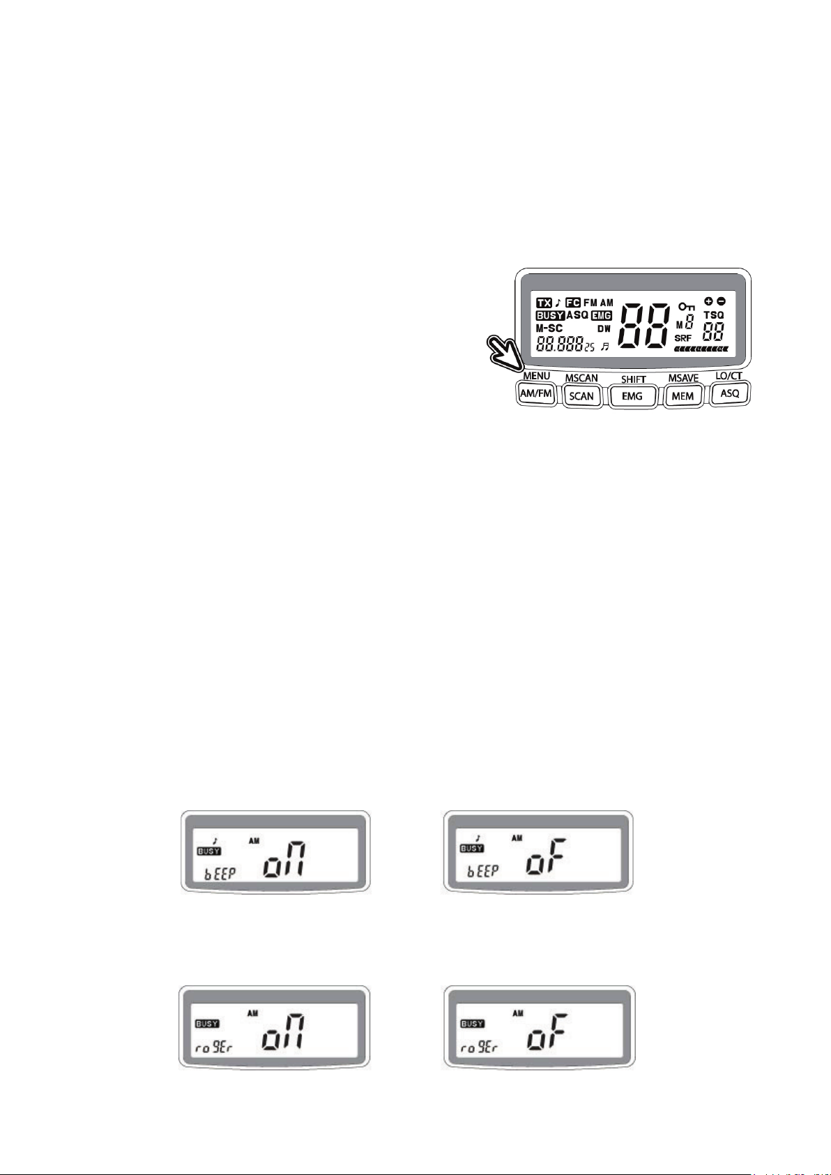
55
la banda CB.
Durante periodos de fuerte propagación de sobrealcance de onda, fuerte actividades
solares y señales de interferencia muy fuerte puede abrirse de cuando en cuando sin
que se oiga una señal de voz. En tales casos puede ser mejor usar la supresión de
estática estándar en lugar del ASQ. ¡Se puede encontrar un botón ASQ adicional en el
micrófono!
Funcionamiento de las funciones secundarias
MENÚ
Este botón de MENU puede controlar cuatro
funciones del SUB MENÚ en secuencia.
Para iniciar el MENU, por favor, considere que se
trata de una función secundaria como todas las
demás que se describen en este capítulo.
• Debe pulsar el botón FUNCIÓN (botón de supresión de estática FC) primero.
• La pantalla mostrará FC
• Ahora pulse el botón MENU (AM/FM)
Puede disponer de:
1) Encendido/Apagado del pitido del teclado
2) Encendido/Apagado del pitido Roger
3) Selección de color de retroiluminación de LCD
4) Retroiluminación LCD (atenuado y brillante).
La selección se hará pulsando los botones ARRIBA o ABAJO del micrófono o
mediante el conmutador de canal giratorio.
• Vuelva a pulsar MENU 1 x o más a menudo para fijar la selección y el siguiente
paso
1) Beep on/off – se trata del tono del pitido del teclado
2) Roger Beep on/off – se trata de pitido del tono breve que señala el final de cada
transmisión, tras soltar el botón PTT de la emisora de llamada del micrófono
Español
Page 56

56
Funcionamiento de las funciones secundarias
3) Selección del color de la retroiluminación LCD (verde/rojo)
4) Control de brillo de la retroiluminación LCD (más tenue → brillante)
MSCAN
La propiedad de búsqueda del canal en la memoria
permite que la radio busque de forma automática
en los 5 canales memorizados.
• Para acceder, pulse FC y MSCAN
• M-SC aparecerá en la pantalla LCD.
Ahora la radio busca de forma automática sólo los canales memorizados y se detiene
cuando se detecta una radio sobre tráfico.
Nota: ¡Por favor, programe algunos canales de su elección como canales
memorizados!
Véase el capítulo de MS AVE en la página siguiente.
CAMBIO
El botón de función es para SHIFT un acceso
instantáneo a la llamada de conductores de
camiones de emergencia o llamadas la canal 19.
Con SC + SHIFT puede cambiar entre el CH 19 y el
canal operativo usado previamente.
Español
Page 57

57
MSAVE
≫ Función de BLOQUEO
≫ CT (Sistem a de supresión de estática codificado de tono continuo)
Este botón MSAVE se usa para guardar cualquier
canal en los botones de memoria desde M1 a M5
Para guardar canales:
• Seleccione el canal que desee con el botón
giratorio o ARRIBA/ABAJO
• Pulse FC + MS AV E/MEM
• Puede elegir cualquier número de canal de la memoria con un botón desde
MENU (M1) hasta LO/CT (M5)
LO/CT
La función de bloqueo le permite bloquear
todos los botones de la radio.
Por lo tanto, no pueden activarse por entradas
erróneas o de forma accidental.
• Pulse ″FC″ y posteriormente ″LO/CT″
Vuelva a usar el mismo procedimiento posteriormente para volver a desbloquear los
botones.
Nota: Si la radio dispone de un panel CTCSS opcional instalado. No puede poner en
funcionamiento la función de bloqueo.
Opcional/otra versión
Se trata de una función opcional mediante la instalación del módulo de tono CTCSS.
Puede usar las funciones de codificación de 38 CTCSS de (Sistema de supresión de
estática de Tono CodificadoC uandoSadquiera una radio con el modulo de tono 38
opcional instalado.
La versión CTCSS le permite grupos de usuarios cerrados dentro de la banda CB y
evita cualquier apertura de la supresión de estáticos por otras emisoras. Sólo se
pueden oír las emisoras con el código CTCSS correcto en sus transmisiones.
–
Español
Page 58

58
Especificaciones técnicas AE 6490/AE 6491
≫ General
TRANSMISOR
SINTENTIZADOR PLL CONTROLADO
POR CRISTAL
RECEPTOR
CONVERSIÓN DOBLE,
SISTEMA
FUNCIONAMIENTO DE TENSIÓN
AE 6490: CC 12 V, AE 6491: CC 24 V
TEMPERATURA
-10˚ a +55˚C
PASO DE CANALES
10 kHz
DIMENSIONES
188(A) X 57(A) X 158(D) mm
PESO
1,9 kg con accesorios estándar
TOMA SPK EXTERNA DE 3,5 mm
TIPO DE MONO
TIPO UHF (PL) ANT. CONECTOR
SO 239 (Toma de 50 Ohmios para tomas
PL 259)
MICRÓFONO CONDENSOR Y TOMA
Corresponde a un cableado de toma de
6 patillas Albrecht & GDCH excepto PIN
4
≫ TRANSMISOR
POTENCIA DE SALIDA
FM 4 W/AM 4 VATIOS
ALCANCE DE FRECUENCIA
26,965-27,405 MHz
TOLERANCIA DE FRECUENCIA
+/- 100 Hz
SENSIBILIDAD DE MODULACIÓN
2,5 mV (ENTRADA DE 1250 HZ)
CAPACIDAD DE MODULACIÓN
AM 85%/FM 2,0 KHZ
≫ RECEPTOR
SENSIBILIDAD
AM: 0,5 µV (SINAD 10 dB), FM: 0,5 µV
(SINAD 20 dB)
SUPRESIÓN DE ESTÁTICA cerca
Hasta 1000 µV
SUPRESIÓN DE ESTÁTICA
AUTÓMÁTICA
0,5 µV
RATIO S/N
40 dB
DISTORSIÓN
3%
SENSIBILIDAD MÉTRICA S DE S9
100 µV
Potencia de salida de audio
mínimo 4 vatios a 8 ohmios
≫ CONDICIONES DE PRUEBA
FUENTE DE ALIMENTACIÓN
12 V (AE 6490) o 24 V CC (AE 6491)
IMPEDANCIA DE CARGA ANT
50 ohmios
IMPEDANCIA DE CARGA DE AUDIO
8 ohmios de impedancia, 4 ohmios
posible
DE 6 PATILLAS
SUPERHETERODINO
Español
Page 59

59
Atención al cliente y garantía
≫
≫
Problemas y soluciones
Compruebe al principio la alimentación y el fusible. Puede existir un problema con la
alimentación, cuando no aparece ninguna luz o pantalla tras encenderlo. En caso de
que la unidad funcione de forma extraña, desconecte el cable de alimentación (o
extraiga el fusible del soporte), mientras la radio permanece encendida; espere un
poco (mínimo 10 segundos), y posteriormente vuelva a conectar el cable de
alimentación.
Otro método es reiniciarla a la "Configuración de fábrica por defecto". Este reinicio
asimismo puede provocar el cambio de país y el ultimo canal usado - la radio se
vuelve a iniciar como una radio nueva que todavía no se ha conectado.
• Apagar la radio
• Pulse el botón AM/FM y MEM y manténgalos pulsados durante el encendido
de la radio
• Soltar botones
• La pantalla muestra rS y tras un breve periodo de tiempo la radio vuelve a
funcionar. En la mayoría de los casos se restauran ahora las funciones de la
radio.
• Compruebe el conector de la antena y del micrófono.
Garantía europea de 2 años
El distribuidor, minorista o establecimiento donde haya adquirido la radio garantiza al
comprador original de este producto que en caso de que este producto o cualquier
componente del mismo, bajo condiciones de uso normales, presentase defectos en
material o mano de obra en los 2 años siguientes contados a partir de la fecha de
compra original, se repararán tales defectos o se sustituirá por un producto Nuevo o
reparado sin cargo por los componentes o por la mano de obra. Para obtener la
reparación o el mantenimiento dentro de las condiciones de la garantía, debe
entregarse el producto con la prueba de la cobertura de la garantía (por ejemplo, copia
de la factura), especificación de defecto(s), al distribuidor, concesionario o su socios
de reparto autorizado.
No se asume ninguna responsabilidad para el alcance de la comunicación de este
producto. La garantía no es de aplicación a cualquier producto o componente del
mismo que haya sufrido o presente daños debido a modificaciones, una instalación
inadecuada, un manejo incorrecto, un uso incorrecto, negligencia, accidente o por la
retirada o degradación de la etiqueta del número de serie de fábrica. La garantía no es
de aplicación a los accesorios o a aquellos problemas causados por accesorios no
autorizado o recomendados salvo el micrófono que se adjunta, antenas externas,
alimentaciones externas o sobrevoltaje causado por alimentaciones externas, rayos o
defectos de sobrevoltaje mediante antenas u otros cables, ventanas rotas o que
presenten daños y componentes de la carcasa.
Rogamos se ponga en contacto con el distribuidor o con la persona donde adquirió la
radio CB, o se ponga en contacto con nuestros servicio de reparación en Alemania
directamente.
Español
Page 60

60
Dónde encontrar asesoramiento de mantenimiento y documentación del mismo
Dirección de correo
electrónico:
service@alan-electronics.de
Descarga de servicios
www.service.alan-electronics.de
Preguntas sobre
reparación:
Teléfono:
+49 6103 9481-22
(precios normales para la red fija alemana)
La documentación técnica completa se actualiza de forma regular. Puede descargar
las últimas versiones de los manuales de usuario, documentación técnica y
declaración de conformidad, así como consejos de mantenimiento, o preguntas
frecuentes en cualquier momento desde nuestro servidor en la dirección
http://www.service.alan-electronics.de
En caso de que tuviera algún problema, rogamos lea los consejos de mantenimiento o
las preguntas frecuentes (FAQ) antes de enviar la radio CB a un centro de
mantenimiento. Rogamos tenga en cuenta que la aceptación de AM+FM en los
diferentes países europeos acaba de empezar y puede estar sujeta a cambios
imprevistos. Nuestra página Web le proporcionará la última información sobre el uso
de la radio.
Temas de preguntas técnicas y de reparación:
Si ha adquirido su radio en otro lugar, por favor, póngase en contacto con su
distribuidor local para todas las cuestiones.
Nuestra recomendación:
Antes de devolver una radio, por favor, póngase en contacto con su distribuidor o la
línea de atención al cliente.
Nuestra experiencia nos demuestra que mucho problemas menores pueden
solucionarse mediante una simple llamada telefónica a nuestro servicio de atención al
cliente.
Si es necesario la devolución, la línea de atención al cliente asimismo le dirá la
dirección de nuestro servicio de reparación más cercano y le comentará la forma más
rápida de reparar la radio.
Reciclado de elementos electrónicos
La legislación europea requiere que los elementos electrónicos no se
eliminen con los residuos domésticos. Como la industria ha empezado a
financiar el reciclado de residuos electrónicos, las estaciones de recogida
locales de cualquier lugar están preparadas para aceptar elementos
electrónicos defectuosos de forma gratuita de los usuarios.
Español
Page 61

61
≫ Detalles técnicos para la transmisión de datos
Cable de la toma del micrófono
Para paquetes de radio y otros
Pin 1
Micrófono de audio
Pin 1
Transmitir audio
Pin 2
PTT-RX (a tierra para la recepción)
Pin 2
Recibir audio
Pin 3
PTT-TX (a tierra para la transmisión)
Pin 3
Tecla PTT
Pin 4
Botones Arriba, Abajo y ASQ
Pin 4
¡No lo conecte!
Pin 5
Toma a tierra
Pin 5
Toma a tierra
Pin 6
+ Tensión para la alimentación del
micrófono si es necesario
Pin 6
¡No lo conecte!
40
FM
Comentarios
No se permiten radios con cambio de país. Por
Austria.
La radio puede usarse para la transmisión de voz y datos así como para el
funcionamiento de la pasarela de Internet. Se pueden establecer las conexiones
únicamente mediante el conector del micrófono. Para la transmisión de datos, por
favor, use los canales de datos dedicados que pueden variar de país a país.
Cerca de la frontera suiza, le recomendamos amablemente que no use el CH 40 para
la transmisión de datos ya que es un canal de llamadas de voz establecido en Suiza.
Información legal y declaración de conformidad
Pasaporte de radio Albrecht
Para las normas de uso y programación de la AE 6490/AE6491 (sujeto a cambios con
fecha mayo 2014) en países que aplican la directiva europea de R & TTE:
País
Austria
Bélgica
Bulgaria
Croacia
Chipre
República Checa
Dinamarca
Estonia
Finlandia
Francia
80/40 40/40
favor, pregunte a su distribuidor para obtener
información sobre una versión de esta radio para
Español
Page 62

62
Alemania
Las estaciones bases situadas en la cercanía de la
funcionamiento de los canales 41-80.
Es necesario el registro para los nacionales.
Visitantes extranjeros gratis.
En funcionamiento FM sólo se permite en los
canales 1-40 y 70-80.
Es necesario el registro y las tasas regulares para
los habitantes. Visitantes extranjeros gratis.
frontera (excepto CZ) necesitan una licencia para el
Grecia
Hungría
Islandia
Irlanda
Italia
Letonia
Liechtenstein
Lituania
Luxemburgo
Malta
Mónaco
Países Bajos
Noruega
Polonia
Portugal
Rumanía
San Marino
Eslovaquia
Eslovenia
España
Suecia
Suiza
Reino Unido
Español
Page 63

63
Declaración de conformidad
Radio CB
Albrecht
AE 6490/AE 6491
www.alan-electronics.de
http://www.service.alan-electronics.de
Por la presente, declaramos que este producto:/Wir erklären hiermit, dass unser Produkt
Satisface toda la normativa técnica aplicable al producto dentro del ámbito de las directivas del
consejo de la UE, estándares europeos y aplicaciones de frecuencia nacionales:/ alle
technischen Anforderungen im Geltungsbereich der EU Richtlinien, europäischer Normen und
nationaler Frequenzanwendungen einhält:
73/23/EEC, 89/336/EEC, 2004/108/EG y 99/5/EC
EN 300 135-2 V.1.2.1/EN 300 433-2 V.1.3.1
EN 301 489-1 V.1.8.1, EN 301 489-13 V.1.2.1, EN 60 950-1: 2006 segunda edición
Alle für das Produkt vorgeschriebenen Funktestreihen wurden durchgeführt.
Se han realizado todas las pruebas esenciales a la radio. /
Alan Electronics GmbH
Daimlerstr. 1 k
Esta declaración se realiza bajo nuestra sola responsabilidad. Basándose en aplicaciones de
frecuencias no totalmente armonizadas, la radio CB puede usarse únicamente en los países
enumerados según la programación de canal seleccionada y conforme a las restricciones
nacionales existentes para AM + FM, si tales todavía fueran de aplicación.
Diese Erklärung wird unter unserer alleinigen Verantwortung abgegeben. Dieses Funkgerät
darf wegen der noch nicht überall harmonisierten Frequenzanwendungen in AM + FM in
einigen Ländern nur eingeschränkt oder gar nicht betrieben werden, entsprechend den noch
geltenden nationalen Regelungen.
Alan Electronics GmbH declare, bajo su responsabilidat, que este aparato cumple con lo
dispuesto en la Directiva 99/05/CE, del Parlamento Europeo y del Consejo de 9 de marzo
de 1999, transpuesta a la legislacion espanola mediante el Real Decreto 1890/2000, de
20 de noviembre.
D- 63303 Dreieich
Punto de contacto/Ansprechpartner: Dipl.-Phys. Wolfgang Schnorrenberg
Lugar y fecha de emisión:
Lütjensee, 21.9.2012
© Alan Electronics GmbH, May 2014
(Firma)
Dipl.-Phys. Wolfgang Schnorrenberg
Alan Electronics GmbH
Español
Page 64

64
Español
 Loading...