


HYDRO 15
FLEX WING
MOWER
Published 09/06 |
Part No. 00756179S |
PRODUCT SERVICE MANUAL
12 |
1212 |
121212 |
|
121212 |
121212 |
121212 |
121212 |
12122 |
121212 |
121212 |
121212 |
12121212 |
121212 |
121212 |
121212 |
121212 |
121212 |
121212 |
1212 |
12122 |
121212 |
121212 |
121212 |
12121212 |
12121212 |
121212 |
121212 |
121212 |
121212 |
121212 |
121212 |
121212 |
121212 |
121212 |
1212 |
121212 |
12 |
1212 |
|
2 |
|
2345 |
|
1234 |
|
|
|
234 5 |
1234 |
123 4 |
1234 |
1234 |
1234 |
234 5 |
123 4 |
123 4 |
123 4 |
123 4 |
123 4 |
234 5 |
123 4 |
123 4 |
123 4 |
123 4 |
123 4 |
234 5 |
123 4 |
123 4 |
123 4 |
123 4 |
123 4 |
234 5 |
123 4 |
123 4 |
123 4 |
123 4 |
123 4 |
234 5 |
123 4 |
123 4 |
123 4 |
123 4 |
123 4 |
234 5 |
123 4 |
123 4 |
123 4 |
123 4 |
123 4 |
234 5 |
123 4 |
123 4 |
123 4 |
123 4 |
123 4 |
234 5 |
123 4 |
123 4 |
123 4 |
123 4 |
123 4 |
234 5 |
123 4 |
123 4 |
123 4 |
123 4 |
123 4 |
2345 |
1234 |
1234 |
1234 |
234 |
1234 |
An operator's manual, parts manual was shipped with the unit shipped from the factory. There may also be other information on this product available, assembly manual, insert sheets and/or special instruction sheets. This manual is designed to be used in conjunction with these other manuals and/or instruction sheets. This manual is not designed to replace any of the other manual. The information is as of the published date, changes may be made to unit without prior notice and/or changes to the tractors which will affect the mounting. Alamo Industrial will not be responsible for the changes that may affect the unit. If manuals are needed contact your local dealer or Alamo Industrial Inc.
ALAMO INDUSTRIAL
1502 E. Walnut Seguin, Texas 78155 830-379-1480
© 2006 Alamo Industrial

TO THE OWNER/OPERATOR/DEALER
All implements with moving parts are potentially hazardous. There is no substitute for a cautious, safe-minded operator who recognizes the potential hazards and follows reasonable safety practices. The manufacturer has designed this implement to be used with all its safety equipment properly attached to minimize the chance of accidents.
BEFOREYOUSTART!! Read the safety messages on the implement and shown in your manual. Observe the rules of safety and common sense!
WARRANTYINFORMATION:
Read and understand the complete Warranty Statement found in this Manual. Fill out the Warranty Registration Form in full and return it to within 30 Days. Make certain the Serial Number of the Machine is recorded on the Warranty Card and on the Warranty Form that you retain.

INTRODUCTION
ABOUT THIS MANUAL:
The intent of this publications to provide the competent technician with the information necessary to perform the CORRECT repairs to the Alamo Industrial Product. This will, in turn provide for complete customer satisfaction
It is hoped that the information contained in this and other Manuals will provide enough detail to eliminate the need for contact of the Alamo Industrial Technical Service Dept. However, it should be understood that many instances may arrive wherein correspondence with the Manufacturer is necessary.
CONTACTING MANUFACTURER: (Please help us Help You! Before You Call! )
Alamo Industrial Service Staff Members are dedicated to helping you solve yours or your customer’s service problem as quickly and efficiently as possible. Unfortunately, we receive entirely to many calls with only a minimum amount of information. In some cases, the correspondent has never gone out to look at the equipment and merely calls inquiring of the problems described to him by the operator or customer.
PART NUMBERS: Part numbers listed in this manual are subject to change without notice as designs are made to adapter to the tractor or for a design improvement. Before ordering parts ALWAYS Measure old part to make certain that is the one you will need. This manual is designed to be used along with the Parts and Operators Manual.
Most calls received by Alamo Industrial Service can be classified into approx. 6 general categories.
1.Hydraulic or Mechanical Trouble Shooting.
2.Request for Technical Information or Specifications.
3.Mounting or Fitting Problem.
4.Special Service Problem.
5.Equipment Application Problems.
6.Tractor Problem Inquiries.
HOW YOU CAN HELP:
Make sure the call is necessary! Most of the calls received may not be necessary if the Dealer Service Technician would do the following.
1.Check the Service Information at your Dealership provided by Alamo Industrial, This would include, Service Bulletins, Information Bulletins, Parts Manuals, Operators Manuals or
Service Manuals, many of these are available via the Alamo Industrial Internet site (Alamo - Industrial. Com). Attempt to diagnose or repair problem before calling.
2.If a call to Alamo Industrial is needed, Certain Information should be available and ready for the Alamo Industrial Service Staff. Such information as, Machine Model, Serial Number, Your Dealer Name, Your Account Number and Any other information that will be useful. This information is vital for the development of a prompt and correct solution to the problem. This will also help to develop a database of problems and related solutions, which will expedite a solution to future problems of a similar nature.
3.The technician may be asked to provide detailed information about the problem including the results of any required trouble shooting techniques. If the information is not available, The technician may be asked to get the information and call back. Most recommendations for repairs will be based on the procedures listed in the Service Manual / Trouble Shooting Guide.
CONTACT ALAMO INDUSTRIAL:
Alamo Industrial, 1502 E. Walnut St. Seguin TX. 78155,
Technical Service Dept. PH: 830-379-1480
HYDRO 15 (Service Manual) 09/06
© 2006 Alamo Group Inc. |
Index -1 |

INDEX
Section |
|
|
Page |
Section 1 - Specifications........................................................................... |
|
1-1 to 1-7 |
|
Do Not Do or Allow Items (Read First Thing).......................... |
1-2 |
||
Mower |
Specifications........................................................... |
1-3 to 1-5 |
|
Bolt Torque Specifications Chart........................................... |
1-5 |
||
Pump & Motor Hydraulic Schematic - 15 Foot Model.............. |
1-6 |
||
Pump & Motor Hydraulic Schematic - 10 Foot Model.............. |
1-7 |
||
Section 2 - Pump Service & Repair.......................................................... |
2-1 to 2- 22 |
||
Pump Repair Preparation Procedures................................... |
2-2 |
||
Pump Test Procedure.......................................................... |
2-3 to 2-4 |
||
Pump & Motor Hydraulic Schematic - 15 Foot Model.............. |
2-5 |
||
Pump & Motor Hydraulic Schematic - 10 Foot Model.............. |
2-6 |
||
Recommended & Required Tools.......................................... |
2-7 |
||
Pump Cleaning & Removal................................................... |
2-8 |
||
Pump Component Identification............................................ |
2-9 |
||
Pump Dis-Assembly Preparations........................................ |
2-10 |
||
Pump Dis-Assembly Procedures.......................................... |
2-11 to 2-13 |
||
Pump Component Wear Inspection Guide............................. |
2-14 |
||
Pump Assembly Preparation................................................ |
2-15 |
||
Pump Assembly Procedures................................................ |
2-16 to 2-21 |
||
Pump Recommended Start Up Procedure............................. |
2-22 |
||
Section 3 - Motor Service & Repair.......................................................... |
3-1 to 3-25 |
||
Motor Repair Preparation Procedures................................... |
3-2 |
||
Motor |
Test Procedure.......................................................... |
3-3 to 3-4 |
|
Motor & Pump Hydraulic Schematic - 15 Foot Model.............. |
3-5 |
||
Motor & Pump Hydraulic Schematic - 10 Foot Model.............. |
3-6 |
||
Recommended & Required Tools.......................................... |
3-7 |
||
Motor Cleaning & Removal................................................... |
3-8 |
||
Motor Identification Center & Wings...................................... |
3-8 to 3-9 |
||
Motor Dis-Assembly Preparation (Center).............................. |
3-10 |
||
Motor Dis-Assembly Preparation (Wings).............................. |
3-11 |
||
Motor Component Identification............................................. |
3-12 |
||
Motor Dis-Assembly Procedures.......................................... |
3-12 to 3-15 |
||
Motor Component Wear Inspection Guide.............................. |
3-16 |
||
Motor |
Assembly |
Preparation................................................ |
3-17 |
Motor |
Assembly |
Procedures................................................ |
3-17 to 3-23 |
Motor Recommended Start Up Procedure.............................. |
3-24 |
||
Motor Electrical System (wing Motors).................................. |
3-24 to 3-25 |
||
Section 4 - Spindle Repair......................................................................... |
|
4-1 to 4-10 |
|
Spindle Component Identification.......................................... |
4-2 |
||
Blade Carrier Removal.......................................................... |
4-9 TO 4-10 |
||
Spindle Removal Preparation................................................ |
4-2 |
||
Spindle Housing |
Removal..................................................... |
4-2 to 4-3 |
|
Spindle Housing Dis-Assembly............................................. |
4-3 to 4-5 |
||
Spindle Component Inspection Part Condition........................ |
4-5 |
||
Spindle Assembly Procedure............................................... |
4-5 to 4-9 |
||
Blade |
Carrier Installation...................................................... |
4-9 to 4-10 |
|
|
|
|
|
HYDRO 15 (Service Manual) 09/06 |
|
|
|
© 2006 Alamo Group Inc. |
|
Index -2 |
|

INDEX
Section |
|
|
Page |
Section 4 - Spindle Repair......................................................................... |
4-1 to 4-10 |
||
Spindle |
Component Identification........................................................ |
4-2 |
|
Blade Carrier Removal........................................................................ |
4-9 TO 4-10 |
||
Spindle |
Removal |
Preparation.............................................................. |
4-2 |
Spindle |
Housing |
Removal................................................................... |
4-2 to 4-3 |
Spindle Housing Dis-Assembly........................................................... |
4-3 to 4-5 |
||
Spindle Component Inspection Part Condition...................................... |
4-5 |
||
Spindle |
Assembly Procedure.............................................................. |
4-5 to 4-9 |
|
Blade Carrier Installation.................................................................... |
4-9 to 4-10 |
||
Section 5 - Hydraulic Cylinder Repair & Service.................................... |
5-1 to 5-30 |
||
Wing Lift Cylinders |
|
|
|
Wing Lift & Fold Cylinder Schematic 15 ft............................................ |
5-2 & 5-4 |
||
Wing Lift & Fold Cylinder Schematic 10 ft............................................ |
5-3 & 5-5 |
||
Wing Lift & Fold Cylinder Removal...................................................... |
5-8 |
||
Wing Lift & Fold Cylinder Dis-Assembly.............................................. |
5-8 to 5-10 |
||
Wing Lift & Fold Cylinder Re-Assembly............................................... |
5-10 to 5-14 |
||
Standard Axle Lift Cylinder (Standard 1 Cylinder System) |
|
||
Axle Lift Cylinder Schematic (Standard 1 Cylinder 15 ft)........................ |
5-2 |
||
Axle Lift Cylinder Schematic (Standard 1 Cylinder 10 ft)........................ |
5-3 |
||
Axle Lift Cylinder Removal (Standard 1 Cylinder).................................. |
5-16 |
||
Axle Lift Cylinder Dis-Assembly (Standard 1 Cylinder).......................... |
5-16 to 5-18 |
||
Axle Lift Cylinder Component Inspection (Standard 1 Cylinder)............. |
5-19 |
||
Axle Lift Cylinder Re-Assembly (Standard 1 Cylinder)........................... |
5-19 to 5-21 |
||
Optional Axle Lift Cylinder (Optional 3 Cylinder System) |
|
||
Axle Lift Cylinder Schematic (Optional 3 Cylinder 15 ft)......................... |
5-4 |
||
Axle Lift Cylinder Schematic (Optional 3 Cylinder 10 ft)......................... |
5-5 |
||
Axle Lift Cylinder Removal (Optional 3 Cylinder Axle Level Lift).............. |
5-24 |
||
Axle Lift Cylinder Dis-Assembly (Optional 3 Cylinder Axle Level Lift)..... |
5-24 to 5-26 |
||
Axle Lift Cylinder Component Inspection (Optional 3 Cyl Axle Level Lift). 5-26 to 5-27 |
|||
Axle Lift Cylinder Re-Assembly (Optional 3 Cylinder Axle Level Lift)...... |
5-28 to 5-30 |
||
Section 6 - Hydraulic Tank Repair, Fill And Service............................... |
6-1 to 6-5 |
||
Hydraulic Tank Fluid Level................................................................. |
6-2 |
||
Hydraulic Tank Oil Return Filter.......................................................... |
6-3 |
||
Hydraulic Tank Oil Fill Procedure........................................................ |
6-4 to 6-5 |
||
Section 7 - Speed Increaser (Speed Changer) Repair & Service......... |
7-1 to 7-13 |
||
Speed Increaser To Tractor PTO Mount............................................... |
7-2 to 7-5 |
||
Speed Increaser Component Identification............................................ |
7-6 to 7-7 |
||
Speed Increaser Dis-Assembly For Component Inspection.................... |
7-8 |
||
Speed Increaser Dis-Assembly For Component Re-Placement.............. |
7-8 to 7-9 |
||
Speed Increaser Re-Assembly For Component Re-Placement............... |
7-10 to 7-13 |
||
Section 8 - Tire - Wheel - Hub Repair & Service..................................... |
8-1 to 8-7 |
||
Wheel |
Information.............................................................................. |
8-2 to 8-3 |
|
Wheel Hub Dis-Assembly.................................................................. |
8-3 to 8-4 |
||
Wheel Hub Re-Assembly................................................................... |
8-5 to 8-7 |
||
|
|
||
HYDRO 15 (Service Manual) 09/06 |
|
||
© 2006 Alamo Group Inc. |
Index -3 |
|
|

INDEX
Section 9 - Blades & Blade Carriers Service & Repair.......................... |
9-1 to 9-3 |
|
Blade Carrier Service & Repair............................................................ |
9-2 |
|
Blade Bolt Service & Repair............................................................... |
9-3 |
|
Section 10 - leveling Mower Service & Repair........................................ |
10-1 to 10-6 |
|
Tongue Clevis Connection.................................................................. |
10-2 |
|
Leveling Rod Component Identification................................................. |
10-3 |
|
Assembling Control Rods...................................................... |
10-4 |
|
Adjusting |
Control Rods..................................................................... |
10-5 |
Adjusting |
Wing Axles........................................................................ |
10-6 |
Leveling |
Mower.................................................................................. |
10-1 to 10-6 |
Section 11 - Trouble Shooting Guide........................................................ |
11-1 to 11-3 |
|
Probable |
Cause & Solutions............................................................... |
11-2 to 11-3 |
HYDRO 15 (Service Manual) 09/06 |
|
© 2006 Alamo Group Inc. |
Index -4 |

Section 1
HYDRO 15
Model
Specifications
HYDRO 15 (Service Manual) 09/06
© 2006 Alamo Industrial |
Section 1 - 1 |

SPECIFICATIONS - HYDRO 15 FLEX WING
READ THIS BEFORE BEGINNING
ASSEMBLY, REPAIRS OR TESTING:
The Hydro 15 has electric components:. The electric components can be damaged if care is not taken when performing repairs, testing, dis-assembly or re-assembly. Mower must be maintained in a safe position at all times. The hydraulic system must be protected from contamination at all times.
DO NOT
1.DO NOT start any repairs, testing or dis-assembly before the mower is secured with the wings in the lowered position and the mower hydraulic axle system released to lower the mower completely. If the Hydraulic axle cylinders or turnbuckles are to be removed or serviced make certain mower decks are securely supported by strong jack stands. Make certain mower is in secure clean environment when working on hydraulic system. If mower is connected to tractor must be secured to prevent someone from starting it and parked in accordance with the tractor manufactures recommendation, See tractor operators manual and/or decals for parking tractor securely.
2.DO NOT open any hydraulic component on mower before the entire exterior of the mower and hydraulic components have been cleaned of all debris or any thing that would contaminate the hydraulic system. When working on the hydraulics always keep the hoses sealed by using temporary caps to plug them, do not just leave them open to the elements
3.DO NOT short any wires across or allow them to be shorted out on the electric components of mower. Do not allow or attempt to jump across any wires or supply them with alternate power source.
4.DO NOT install higher rated fuses than are recommended by manufacturer for any components.
5.DO NOT do any welding on unit unless the electrical components are unplugged first, this is to prevent a power surge going into switch and/or solenoids (THIS IS VERY IMPORTANT). This could also apply to the tractor components. Check Tractors repair guide for specific instruction about tractor model and type.It is recommended that mower be disconnected from tractor when being repaired.
6.DO NOTattempttorepairoradjusta component thatisnotintendedto be repaired, examplesealedcomponents as there are no serviceable components inside.
7.DO NOT let anyone attempt any testing or repairs unless they are an experienced and qualified technician. Technicians must have proper tools, gauges, meters etc. to perform proper diagnosis and/or repairs.
8.DO NOT perform any repairs with dirty tools or in dirty area. When working on hydraulic components, keeping system clean and free of contamination is important.
9.DO NOT re-use old oil if it is contaminated, re-install dirty components or not completely clean the system after a repair if there is a possibility of oil contamination. Example: If the right wing motor has metal in it from a failure the left wing motor is most likely also contaminated. The center motor, and possibly the pump, the hoses, the tank, the filter housings as well as the filters will most likely need cleaning and or replacing.
10.DO NOT start or engage system if the oil level is not at the proper level or condition. Never start or run unit low or out of oil.
11.DO NOT install / add any oil unless you know it is the correct type and the container is clean. Make certain the oil is not contaminated with dirt or any liquid. It is recommended that any oil installed be done using a commercial oil buggy with a filtered system, a buggy system can also be used to clean the oil.
HYDRO 15 (Service Manual) 09/06 |
|
© 2006 Alamo Industrial |
Section 1 - 2 |
SPECIFICATIONS - HYDRO 15 FLEX WING
General Specifications for Mower:
Tractor Horse Power Required........................................ |
70 - 90 HP |
|||||
Tractor PTO RPM......................................................... |
|
540 RPM required |
||||
Mower |
|
Paint |
Colors |
....................................................... |
Alamo Yellow Std / Other Colors Optional |
|
Mower |
|
Gross |
Weight..................................................... |
4200 lbs. w/ Chain Guards (this can vary w/ wheel type) |
||
Mower Tongue Weight................................................... |
Approx 2200 lbs w/ Wings lowered |
|||||
Cutting |
Capacity........................................................... |
|
Grass & Up To 1-1/2" dia Brush (Max) |
|||
Mower Overall Length.................................................... |
199" Front To Back |
|||||
Mower Overall Width..................................................... |
186.5" w/Wings Down & 96" w/ Wings Folded (this can |
|||||
|
|
|
|
|
|
be affected by tire size, type, & wing axle adjustment) |
Number Blade Carriers................................................... |
3 on 15 ft Model & 2 on 10 Ft Model |
|||||
Cutting |
Width |
Options................................................... |
15 Ft or 10 Ft Model |
|||
|
|
Over All Cutting Width... (15 Ft Model)................ |
180" Center & Wings Overall Cutting Width |
|||
|
|
|
|
|
(10 Ft. Model)............... |
124-1/2" Center & Wing Overall Cutting Width |
Cutting |
Height............................................................... |
|
2" Down to 15" Up w/ 700:15 Pneumatic Tires (Cutting |
|||
|
|
|
|
|
|
Height will vary with tire & Wheel sizes) |
|
|
|
|
|
|
2" Down to 12" Up w/ 12" Tires (Cutting Height will vary |
|
|
|
|
|
|
with tire & Wheel sizes) |
Blade Carrier Cutting Width............................................ |
Center & Wing |
|||||
|
|
Center Section.................................................. |
69" (Carrier Cutting Width - Overlap) |
|||
|
|
Left |
Wing.......................................................... |
|
63-1/2" (Carrier Cutting Width - Overlap) |
|
|
|
Right |
Wing....................................................... |
|
63-1/2" (Carrier Cutting Width - Overlap) |
|
|
|
Blade Over Lap Between Wing and Center........... |
8" total overlap (4" center overlap & 4" Wing overlap) |
|||
Blade |
Carrier |
Options.................................................... |
Pan or Bar Carrier |
|||
|
|
Bar |
Carrier |
Size................................................ |
Bar Carrier - 1-1/4" X 6" Bar Size |
|
|
|
Pan |
Carrier |
Size............................................... |
Pan Carrier - 3/16" thick X 2-1/2" high X 37-1/4" dia. pan |
|
|
|
|
|
|
|
w/ 1-1/4" X 6" steel bar w/ cross bar brace. |
Blade |
Carrier |
Mounting.................................................. |
Bolts Direct to Blade Spindle f/ Under Side |
|||
|
|
|
|
|
Bolts........................................ |
Qty 4 |
|
|
|
|
|
Type........................................ |
Allen Head Bolts |
|
|
|
|
|
Torque..................................... |
400 ft lbs |
|
|
|
|
|
Installation............................... |
Use Thread Lock Compound |
|
|
|
|
|
Lockwasher.............................. |
Qty 4 |
Blade |
Options.............................................................. |
|
Fan |
|||
Blade |
Size.................................................................... |
|
|
|
1/2" thick X 3.5" wide X 22-1/4" long (measure blade |
|
|
|
|
|
|
|
length from center of bolt hole to end of blade) |
Blade Rotation.............................................................. |
|
CCW rotation Center & LH Wing, CW RH Wing |
||||
Blade |
Bolt |
Type............................................................ |
|
Bolt On W/ Locknut |
||
|
|
|
|
|
Construction............................. |
Cold Forged and Hardened, w/ 1-1/8" square Shank, |
|
|
|
|
|
Shoulder.................................. |
1/2" High X 1-1/2" dia Shoulder, w/ 1" RH Thread, |
|
|
|
|
|
Bolt Head................................. |
2-7/16" Round Flat Head |
|
|
|
|
|
Bushing.................................... |
2" OD X 1-1/2" ID X 1-1/2" Long Welded into Blade Bar |
|
|
|
|
|
Washer & Nut........................... |
1" Structural Steel Flat Washer & Toplock Locknut |
|
|
|
|
|
Torque...................................... |
300 ft lbs |
Blade Tip Speed............................................................ |
|
Blade Tip Speed Based on Max Pressure & RPM |
||||
|
|
Center Section Blade Tip Speed......................... |
18,262 FPM (Operating Speed) |
|||
|
|
Wing Section Blade Tip Speed........................... |
13,194 FPM (Operating Speed) |
|||
Blade Spindle.............................................................. |
|
1 On Center Section & 1 On Each Wing |
||||
|
|
Spindle Bearing Type........................................ |
Adjustable Roller Bearing Cup & Cone) |
|||
|
|
Spindle Seal..................................................... |
Replaceble Round Seal Bottom & Gasket Seal Top |
|||
|
|
Spindle Lubrication............................................ |
NLGI EP #2 Grease / Grease w/ Grease Gun |
|||
|
|
Spindle Bearing Preload (Required)..................... |
Adjustable (12 to 15 in. lbs. of rolling resistance) |
|||
|
|
|||||
HYDRO 15 (Service Manual) 09/06 |
|
|||||
© 2006 Alamo Industrial |
Section 1 - 3 |
|||||

SPECIFICATIONS - HYDRO 15 FLEX WING
....................................................Blade Spindle Speed |
|
|
Measured RPM at Spindle Shaft |
|||
Center Section Spindle Tip Speed...................... |
731 RPM (Operating Speed) |
|||||
Wing Section Spindle Speed.............................. |
881 RPM (Operating Speed) |
|||||
Spindle to Deck Mounting Bolts......................... |
3/4" Grade 8 Toque to 350 ft. lbs. |
|||||
Hydraulic Pump, Tandem............................................. |
|
Front1/2 of Pump f/ Wing & Rear 1/2 pump of f/ Center |
||||
Pump Type...................................................... |
|
|
Tandem Gear Type - PTO Driven Via Speed Changer |
|||
Pump |
Displacement......................................... |
|
Center = 2.95 C.I.D. |
Wing = 3.6 C.I.D. |
||
Pump HP......................................................... |
|
|
145 HP Dual Stage Gear Type |
|||
Speed Changer Gear Ratio................................. |
1 RPM Input X 4 RPM Output (Increase) |
|||||
Tractor PTO Speed............................................ |
|
540 RPM Required |
|
|||
Pump RPM....................................................... |
|
|
2160 RPM Operating (2750 RPM Max) |
|||
Pump Pressure................................................. |
|
3000 PSI Operating (3600 PSI Max at Max RPM) |
||||
Pump GPM |
Front 1/2 (Wing Motors)............. |
28 GPM Operating (35 GPM at Max RPM) |
||||
|
|
|
Rear 1/2 (Center Motor)............ |
24 GPM Operating (35 GPM at Max RPM) |
||
Hydraulic Motor, Center & Wing..................................... |
1 & 2 on 15 ft Model / 1 & 1 on 10 ft Model |
|||||
Motor Type...................................................... |
|
|
Gear Type |
|
||
Motor HP Rating........... |
Center.......................... |
75 HP @ 3000 PSI |
|
|||
|
|
|
|
Wing........................... |
70 HP @ 2000 PSI |
|
Motor |
Displacement.......................................... |
|
Center = 6.300 C.I.D. |
Wing = 6.375 C.I.D. |
||
Motor Relief Valve Setting.................................. |
Center = 3000 PSI |
Wing = 2000 PSI |
||||
Motor Max Pressure......................................... |
|
Center = 3600 PSI |
Wing = 3000 PSI |
|||
Motor HP Rating at Operating RPM.................... |
Center = 37.8 HP |
Wing = 27.2 HP |
||||
Motor Tip Speed at Operating RPM.................... |
Center = 731 RPM |
Wing = 881 RPM |
||||
Motor Cut Off ... |
Wing Decks.............................. |
Electric Cut Off Standard on Wings |
||||
|
|
|
Center |
Deck............................. |
Tractor PTO Shut Off For Center Deck Standard |
|
Motor Mounting Type........................................ |
|
Bolts Direct to Blade Spindle Asy. |
||||
Motor To Spindle Mounting Bolt Size................. |
1/2" Grade 8 Torque to 95 ft. lbs |
|||||
Hydraulic |
Oil |
Type........................................................ |
|
|
100AW or Equivalent SAE 30 Weight Hyd Oil |
|
Hydraulic |
Oil |
Capacity.................................................. |
|
|
Tank & Cooling Tubes = 35 Gals |
|
Hydraulic |
Tank.............................................................. |
|
|
Weldment, Bolted to Center Section |
||
Hydraulic |
Filter............................................................. |
|
|
2 Micron Filter / Replaceable |
||
Hydraulic Cooling Tube Type.......................................... |
|
3" X 8" Deck Length Weldments (2 each wing & Center) |
||||
Hydraulic Reservoir Pressure......................................... |
|
11 PSI (Return Pressure) |
||||
Mower Deck Leveling Adjustment................................... |
Mechanical f/ Front to Rear (at Assembly Setup & |
|||||
|
|
|
|
|
Self Leveling While Operating) |
|
Mower Center Deck Control Rods................................... |
Dual Control Rods. |
|
||||
Mower Hitch................................................................. |
|
|
|
SelfLeveling |
|
|
Axle Lifting............................... |
|
|
Standard...................... |
Hydraulic Cylinder Center Axle & Lift Screws on Wings |
||
|
|
|
|
Optional....................... |
Hydraulic Cylinder on Center Axle and Wing Axle |
|
Axle Lowering Height Stop......... |
Center Axle.................. |
Clip on Spacers Set Center Cylinder |
||||
Axle Shock Absorber................. |
|
Center.......................... |
Rubber Bump Pads (Standard) |
|||
|
|
|
|
Wing............................ |
Coil Springs each Wing Axle (Standard) |
|
Mower Wing Leveling................. |
|
Standard...................... |
Wing Axle mechanical Screw Lift Adjustment |
|||
|
|
|
|
Optional....................... |
Wing Axle & Center Axle Hydraulic Lift Adjustment |
|
Mower Wing Lift and Fold........... |
Standard..................... |
Hydraulic Cylinder, 1 each Wing |
||||
|
|
|
|
Optional...................... |
Cable Winch and Stand |
|
Wing Lift |
& Fold........................................................... |
|
|
Hydraulic Standard |
|
|
Wing Lift Range........................................................... |
|
|
22° Down & 90° Up |
|
||
Wing Winch Stand.................... |
|
Standard...................... |
Bolt on Weldment |
|
||
Wing Winch............................. |
|
|
Optional....................... |
Manual Operated Cable Lift Winch |
||
Mower Wing Transport............... |
|
Standard.................... |
Welded Bracket and Pin Assembly |
|||
Hydraulic Control Valve.............. |
|
Option.......................... |
Remote 3 Spool (15 ft) or 2 spool (10 ft) w/ Detent |
|||
Hydraulic Control Valve Type...... |
Option......................... |
Open or Closed Center |
||||
Wing Deck Side Skirts.............. |
|
Standard...................... |
10-3/8" High - 1/4" thick |
|||
HYDRO 15 (Service Manual) 09/06 |
|
|
||||
© 2006 Alamo Industrial |
|
|
Section 1 - 4 |
|
||

SPECIFICATIONS - HYDRO 15 FLEX WING
Skid |
Shoes............................... |
Standard...................... |
Standard Center & Wings, Replaceable Bolt on. |
Deck |
Material Thickness............................................... |
|
10 ga. Steel with formed channel reinforcement |
Deck Reinforcement.................. |
Standard.................... |
Hydraulic Oil Cooling Tubes welded to deck |
|
Wheels........................................................................ |
|
6 Standard or 4 Optional |
|
Wheel Type Standard.................................................... |
|
6:00 X 9 Std (Qty 6) |
|
Wheel Type Option........................................................ |
|
15" Wheel less tire |
|
|
|
|
15" Wheel & Pneumatic Tire Asy |
|
|
|
Used or Recapped Airplane Tire & wheel Asy |
|
|
|
Foam Filled Airplane Tire Asy |
Wheel Spacing (Center Axle)......................................... |
|
56" Center Inner Wheel to Center Inner Wheel |
|
Chain Guards............................................................... |
|
5/16" Double Row Standard, Front & Rear |
|
Tractor Drawbar Setting ................................................ |
|
14 " to 16" f/ end PTO Shaft to Clevis Pivot Bolt. |
|
Drawbar Safety Chain.................................................... |
|
Standard |
|
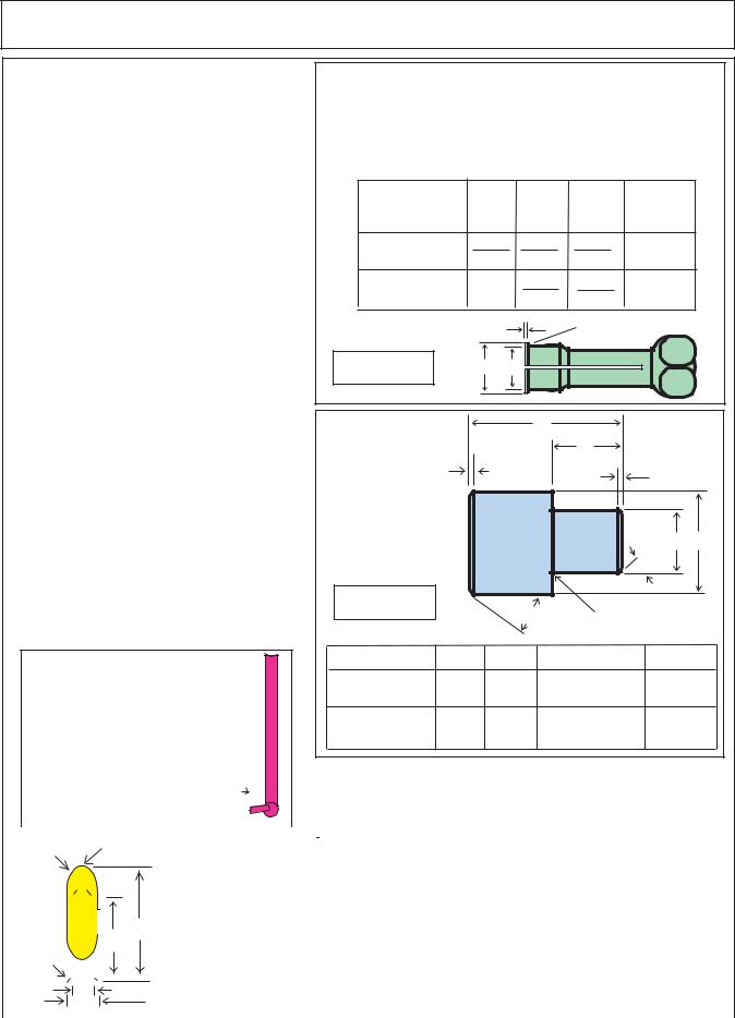
TORQUE VALUES - BOLTS:
Maximum Torque per Bolt Size and Grade, Ft lbs & (Nm)
IMPORTANT ! Listed below IS BOLT TORQUE and NOT APPLICATION TORQUE, Component Application Torque will vary dependimg on what is bolted down and the type material (Metal) that is being bolted together. Thread condition and lubrication will vary Torque settings.
|
Inche Sizes |
|
|
|
Metric Sizes |
|
|||||
Bolt |
2 (B) |
5 (D) |
8 (F) |
ALWAYS |
Bolt |
|
|
|
|||
|
|
|
|
|
Dia. |
4.8 |
8.8 |
10.8 |
|||
Dia. |
|
|
|
|
|
CHECK |
|||||
|
|
|
|
|
mm |
|
|
||||
inch |
|
|
|
|
|
MARKINGS |
|
|
|
||
Plain Head |
3 Dashes |
6 Dashes |
|
|
|
|
|||||
6 |
5 |
7 |
12 |
||||||||
|
ON |
||||||||||
1/4 |
Not Used |
10 |
(14) |
14 (19) |
8 |
11 |
20 |
25 |
|||
TOP |
10 |
40 |
58 |
||||||||
5/16 |
Not Used |
20 |
(27) |
30 (41) |
20 |
||||||
3/8 |
Not Used |
35 |
(47) |
50 (68) |
OF |
12 |
37 |
70 |
105 |
||
7/16 |
14 |
60 |
100 |
140 |
|||||||
35 (47) |
55 |
(75) |
80 (108) |
BOLT |
|||||||
1/2 |
55 (75) |
85 (115) |
120 (163) |
16 |
92 |
155 |
200 |
||||
9/16 |
HEAD |
18 |
118 |
216 |
280 |
||||||
75 (102) |
130 |
(176) |
175 (230) |
||||||||
5/8 |
105 |
(142) |
170 |
(230) |
240 (325) |
OR |
20 |
160 |
270 |
355 |
|
3/4 |
185 |
(251) |
22 |
215 |
330 |
430 |
|||||
300 |
(407) |
425 (576) |
OTHER |
||||||||
7/8 |
160 |
(217) |
445 |
(603) |
685 (929) |
24 |
285 |
500 |
700 |
||
1 |
250 |
(339) |
670 |
(908) |
1030 (1396) |
BOLT |
27 |
450 |
875 |
1000 |
|
30 |
1200 |
1700 |
|||||||||
1-1/8 |
330 |
(447) |
910 (1234) |
1460 (1979) |
DESCRIP- |
600 |
|||||
1-1/4 |
480 |
(651) |
1250 |
(1695) |
2060 (2793) |
33 |
800 |
1600 |
2300 |
||
TIONS |
36 |
|
3000 |
||||||||
|
|
|
|
|
|
900 |
2100 |
||||
HYDRO 15 (Service Manual) 09/06
© 2006 Alamo Industrial |
Section 1 - 5 |
SPECIFICATIONS - HYDRO 15 FLEX WING
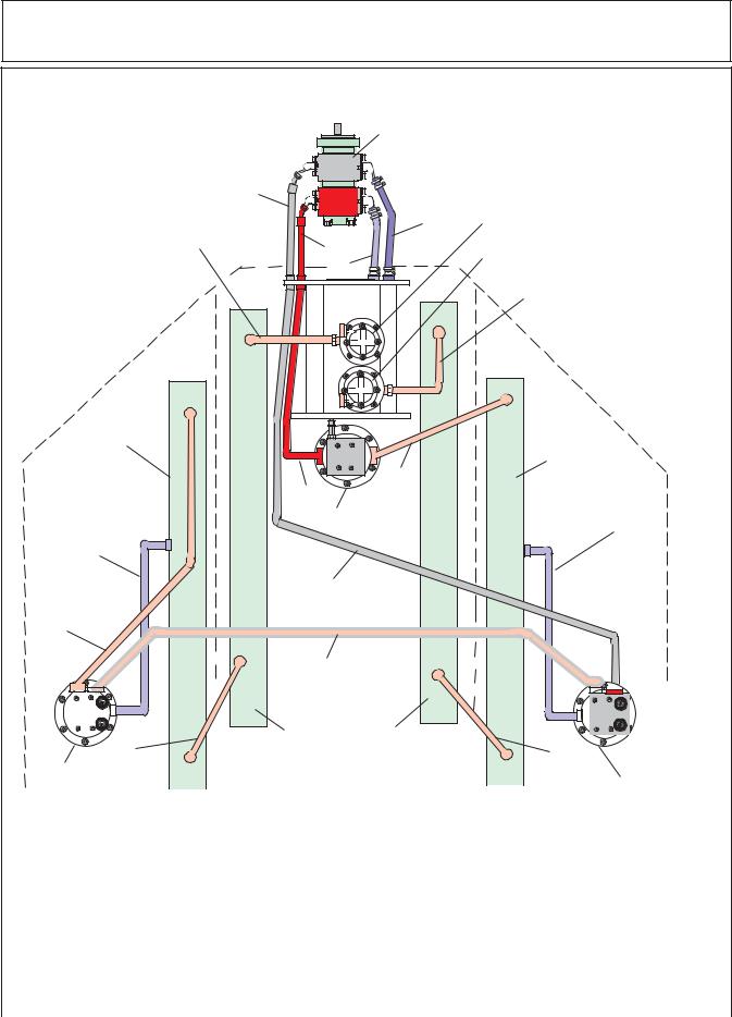
15 FT - PUMP & MOTOR HYDRAULIC SCHEMATIC
CAUTION ! |
|
|
|
1 |
|
NEVER Connect Pump Pressure |
|
|
|
|
|
|
|
|
|
|
|
Line direct to cooling tubes, as it will |
1 |
1 |
|
|
|
|
|
|
|
|
|
damage the tubes. |
1 |
1 |
12 |
|
|
1 |
1 |
|
|
||
|
|
|
23 |
|
|
4 |
1 |
1 12 |
|
20 |
|
|
3 |
||||
|
|
|
1223 |
||
|
|
|
23 |
|
|
15 |
|
5 |
|
|
21 |
|
|
2 |
12 |
23 |
|
|
|
|
|||
|
|
|
|
3 |
|
|
12345678901234567890123456 |
|
|||
|
2345678901234567890123456 |
|
|||
|
2345678901234567 |
|
11 |
||
|
2345678901234567 |
|
|||
|
2345678901234567 |
|
|
||
|
2345678901234567 |
|
|
||
|
2345678901234567 |
|
|
||
|
2345678901234567 |
|
|
||
|
2345678901234567 |
|
|
||
|
2345678901234567 |
|
|
||
|
2345678901234567 |
|
|
||
|
2345678901234567 |
|
|
||
|
2345678901234567 |
|
|
||
|
2345678901234567 |
|
|
||
|
2345678901234567 |
|
|
||
|
2345678901234567 |
|
|
||
|
2345678901234567 |
|
|
||
|
2345678901234567 |
|
|
||
|
2345678901234567 |
|
|
||
|
2345678901234567 |
|
|
||
|
2345678901234567 |
|
|
||
|
2345678901234567 |
|
|
||
|
2345678901234567 |
|
|
||
|
2345678901234567 |
|
|
||
|
2345678901234567 |
|
|
||
|
2345678901234567890123456 |
|
|||
L-Wing |
|
|
|
|
R-Wing |
Cooling |
|
|
|
|
|
|
|
|
|
Cooling |
|
Tube |
|
|
|
|
|
|
|
|
9 |
Tube |
|
|
|
|
|
||
|
6 |
|
|
|
|
|
8 |
|
|
|
|
|
|
|
|
12 |
|
|
|
|
|
|
|
19 |
|
|
|
|
|
|
7 |
|
|
|
|
18 |
|
|
|
|
|
|
14 |
|
|
|
|
|
|
|
|
|
|
|
|
|
|
|
Center (LH & RH) |
|
|
|
|
|
|
|
|
|
|
|
|
|
|
|
|
|
|
|
|
|
|
|
|
|
|
|
|
|
|
|
|
|
|
|
|
||
|
|
|
|
|
|
|
|
|
|
|
|
|
|
|
|
|
|
|
|
|
|
|
||
|
|
|
|
|
|
|
|
|
|
|
|
|
|
|
|
|
|
|
|
|
|
|
||
|
|
|
|
|
|
|
|
|
|
|
|
|
|
|
|
|
|
|
|
|
|
|
||
|
|
|
|
|
|
|
|
|
|
|
|
|
|
|
|
|
|
|
|
|
|
|
||
|
|
|
|
|
|
|
|
|
|
|
|
|
|
|
|
|
|
|
|
|
|
|
||
|
|
21 |
|
|
|
|
10 |
|
|
|
|
|
|
|
||||||||||
|
|
|
|
|
|
|
|
|
|
|
|
|||||||||||||
|
|
|
|
|
|
|
|
|
|
|
|
|||||||||||||
|
|
|
|
CoolingTubes |
|
|
|
|
|
|
|
|
||||||||||||
|
20 |
|
|
|
|
|
|
|
|
|
|
|
|
|
13 |
|
||||||||
|
|
|
|
|
|
|
|
|
|
|
|
|
|
|
|
|
||||||||
Item |
Description |
|
Item |
|
|
|
|
|||||||||||||||||
|
Description |
|||||||||||||||||||||||
1 |
Tandem Pump Asy |
|
12 |
Case Drain (R- Wing Motor to Cooling Tube) |
||||||||||||||||||||
2 |
Suction (Tank to Wing Pump) |
|
13 |
Wing Motor Asy (R- Wing) |
||||||||||||||||||||
3 |
Suction (Tank to Center Pump) |
|
14 |
Return / Pressure (f/ R-Wing to L-Wing Motor) |
||||||||||||||||||||
4 |
Pressure (Pump to Bulk Head Fitting) |
15 |
Return (Center Cooling Tube to Filter / Tank) |
|||||||||||||||||||||
5 |
Pressure (Pump to Bulk Head Fitting) |
16 |
Return Filter & Gauge (Wing Motors Return) |
|||||||||||||||||||||
6 |
Pressure (Bulk Head Fititng to Center Motor) |
17 |
Return Filter & Gauge (Center Motor Return) |
|||||||||||||||||||||
7 |
Pressure (Bulk Head Fitting to Wing Motors) |
18 |
Return (L-Wing Motor to Cooling Tube) |
|||||||||||||||||||||
8 |
Motor Asy (Center Sction Motor) |
|
19 |
Case Drain (L-Wing Motor to Cooling Tube) |
||||||||||||||||||||
9 |
Return (Center Motor to Wing CoolingTube) |
20 |
Wing Motor Asy (L-Wing) |
|||||||||||||||||||||
10 |
Return (Wing Tube to Center Cooling Tube) |
21 |
Return (L-Wing Tube to Center Cooling Tube) |
|||||||||||||||||||||
11 |
Return (Center Coolingg Tube to Fiter / Tank) |
|
|
|
|
|
|
|
|
|
|
|
|
|
||||||||||
|
|
|
|
|
|
|
|
|
|
|
|
|
|
|
|
|
|
|
|
|
|
|
|
|
HYDRO 15 (Service Manual) 09/06 |
|
|
|
|
|
|
|
|
|
|
|
|
|
|
||||||||||
© 2006 Alamo Industrial |
|
Section 1 - 6 |
||||||||||||||||||||||
SPECIFICATIONS - HYDRO 15 FLEX WING
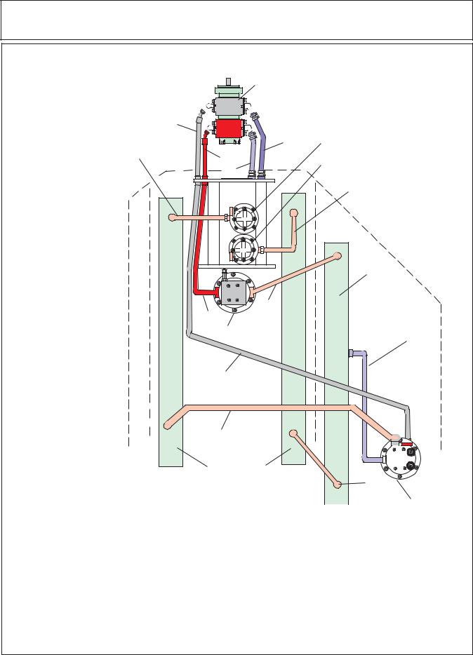
10 FT - PUMP & MOTOR HYDRAULIC SCHEMATIC
CAUTION ! |
|
|
1 |
|
NEVER Connect Pump Pressure |
|
|
|
|
1 |
|
|
|
|
Line direct to cooling tubes, as it will |
|
|
|
|
1 |
|
|
|
|
damage the tubes. |
12 |
|
|
|
|
1 |
23 |
|
|
4 |
|
23 |
|
|
1 |
12 |
|
|
|
1 |
|
|
16 |
|
|
|
|
||
|
1 12 |
3 |
||
|
|
123 |
||
15 |
5 |
|
|
17 |
|
2 |
12 |
23 |
|
|
|
12 |
23 |
|
|
23456789012345678901234567 |
11 |
||
|
2345678901234567 |
|
||
|
2345678901234567 |
|
||
|
2345678901234567 |
|
|
|
|
2345678901234567 |
|
|
|
|
2345678901234567 |
|
|
|
|
2345678901234567 |
|
|
|
|
2345678901234567 |
|
|
|
|
2345678901234567 |
|
|
|
|
2345678901234567 |
|
|
|
|
2345678901234567 |
|
|
|
|
2345678901234567 |
|
|
|
|
2345678901234567 |
|
|
|
|
2345678901234567 |
|
|
|
|
2345678901234567 |
|
|
|
|
2345678901234567 |
|
|
|
|
2345678901234567 |
|
|
|
|
2345678901234567 |
|
|
|
|
2345678901234567 |
|
|
|
|
2345678901234567 |
|
|
|
|
2345678901234567 |
|
|
|
|
2345678901234567 |
|
|
|
|
2345678901234567 |
|
|
|
|
23456789012345678 |
|
|
|
|
1234567890123456789012345 |
|
||
|
|
|
|
R-Wing |
|
|
|
|
Cooling |
|
|
|
9 |
Tube |
|
6 |
|
|
|
|
|
|
|
|
|
8 |
|
|
12 |
|
|
|
|
|
|
7 |
|
|
|
|
14 |
|
|
|
|
|
|
Center (LH & RH) |
|
|
|
|
|
|
|
|
|
|
|
||
|
|
|
|
|
|
|
|
|
|
|
|
|
|
|||
|
|
|
|
10 |
|
|
|
|
|
|
||||||
|
|
|
|
|
|
|
|
|
|
|||||||
|
|
|
|
|
|
|
|
|
|
|||||||
|
|
|
CoolingTubes |
|
|
|
|
|
|
|
|
|||||
|
|
|
|
|
|
|
|
|
|
|
||||||
|
|
|
|
|
|
|
13 |
|
||||||||
|
|
|
|
|
|
|
|
|
|
|||||||
|
|
|
|
|
|
|
|
|
|
|||||||
Item |
Description |
Item |
|
|
|
|
|
|||||||||
Description |
||||||||||||||||
1 |
Tandem Pump Asy |
12 |
Case Drain (R- Wing Motor to Cooling Tube) |
|||||||||||||
2 |
Suction (Tank to Wing Pump) |
13 |
Wing Motor Asy (R- Wing) |
|||||||||||||
3 |
Suction (Tank to Center Pump) |
14 |
Return (R-Wing Motor to Cooling Tube) |
|||||||||||||
4 |
Pressure (Wing Pump to Bulk Head Fitting) |
15 |
Return (Center Cooling Tube to Filter / Tank) |
|||||||||||||
5 |
Pressure (Center Pump to Bulk Head Fitting) |
16 |
Return Filter & Gauge (Wing Motor Return) |
|||||||||||||
6 |
Pressure (Bulk Head Fititng to Center Motor) |
17 |
Return Filter & Gauge (Center Motor Return) |
|||||||||||||
7Pressure (Bulk Head Fitting to Wing Motor)
8Motor Asy (Center Sction Motor)
9Return (Center Motor to Wing CoolingTube)
10Return (Wing Tube to Center Cooling Tube)
11Return (Center Coolingg Tube to Fiter / Tank)
HYDRO 15 (Service Manual) 09/06
© 2006 Alamo Industrial |
Section 1 - 7 |

NOTES
HYDRO 15 (Service Manual) 09/06 |
|
© 2006 Alamo Industrial |
Section 1 - 8 |

Section 2
HYDRO 15
Pump
Service & Repair
HYDRO 15 (Service Manual) 09/06
© 2006 Alamo Industrial |
Section 2 - 1 |

PUMP SERVICE & REPAIR
Recommended Reading Before any Service Work Begins:
1.Read this section completely before starting inspection or repair to the mower hydraulic system to become familiar with its components.
2.Identify the model of the mower model number, serial number and other information that may be needed to identify which components or options that may be on the mower.
3.Make certain the mower and tractor are secured in a safe and proper parked position, hydraulic (axle and wings) lowered. Tractor safely parked according to tractor manufacturers recommendations.
4.Clean the complete hydraulic system in the area of the repairs. Dirt is the enemy of all hydraulic systems and all steps must be taken to keep hydraulic system from being contaminated.
5.Make certain the hydraulic oil is not hot from being operated or tested. All hydraulic components (including hydraulic oil) temperature should not exceed ambient temperatures. If temperature is high it must be allowed top cool before attempting any repairs of the hydraulic system. Caution should be taken, if mower is sitting in hot sun on a very hot day the temperature of the metal and oil can be hot, test the temperature.
6.The drawing and illustrations in this section are to help understand the components of the pump. This section is not intended to be a parts manual or operators manual although it is intended to be used with the other manuals.
7.Use caution if clamping any pump components in a vise or gripping them with any type of tools. The jaws of a vise can damage the surface or it the shape of a component, tools can scratch or damage the surface to render the component un-serviceable
8.These pumps are designed to be assembled to be turned in the direction for which they were built, clockwise or counter clockwise. When the pump is dis-assembled it is very important that you take notice of which components are where and which way they are installed in pump (example Item 5). If these pumps are installed with component in the wrong place and then turned in the wrong direction the pressure will usually blow the input seal out and may damage other components.
9.When making repairs always make certain that the cause of the failure is identified and repaired. Sometimes the cause of the failure is not corrected and another failure occurs rapidly because the cause of the failure is still there.
10.Make certain to use drain pans to catch all oil that may leak out during the testing and/or repair steps. Make certain to keep all hydraulic opening plugged or capped during repairs.
11.Never start the tractor and engage PTO to turn pump, if any hydraulic components have been removed or disconnected, line blockage or oil diverted to the wrong place could to extreme damage to the hydraulic system and/or to the mower deck cooling tubes.
12.The pressure side of the pump hydraulic flow MUST NEVER be sent directly to the deck cooling tubes as the excess pressure will damage them. The hydraulic oil flow can only be sent through the deck cooling tubes when it is being returned to the tank with little or no resistance.
13.Some components of hydraulic system are not meant the be repaired, only replaced. Do Not dis-assemble a component if it is a part intended for replacement only.
14.When storing a pump or its components for any reason it is recommended they be stored in a clean area and covered to protect from any dust, components that have been washed be coated which oil if they are made of material that may rust.
HYDRO 15 (Service Manual) 09/06 |
|
© 2006 Alamo Industrial |
Section 2 - 2 |

PUMP SERVICE & REPAIR
Recommended To Test Old Hydraulic Pump before it is Removed:
(Before Installing a New or Rebuilt Pump).
A.Connect your Flow Meter in Line to test Pressure as unit is started; this is in case the Relief Valve is malfunctioning or has been tampered with. If this is not done you could damage the replacement Pump because you would not Know it until Pump failed from excessive pressure.
B.Before connecting any lines to Pump, fill all Ports with clean Oil to provide initial Lubrication. This is especially important is Pump is located at a higher level than Oil Reservoir.
C.Check Oil level in reservoir, fill to full level if needed, Reservoir must have more Oil than the Pump GPM capacity.
D.After connecting the Lines and mounting the replacement Pump, make sure that Oil is not warmer than Pump temperature. If Oil is warmer than pump run Pump at short intervals till Pump and Oil temperature is equalized. Hot Oil must not be fed into cold Pump.
E.Operate the Pump for at least two minutes at no load and at low RPM (400 RPM min and 1400 RPM max.). Watch Flow Meter Pressure (or Pressure Gauge). During this break-in period, the unit should run free and not develop an excessive amount of heat. Heat should not exceed 100 deg F. above ambient Temperature. If the unit operates properly, speed and pressure can then be increased to normal operating settings.
Increase Pressure in 500 Lbs. PSI increments from start, this should take 4 to 5 minutes to max. PSI allowing 1 minute between increases to check Oil Pressure and Temperature.
F.If normal Pressure and Heat readings are seen then the New or Rebuilt Pump installation should be done, remove Flow Meter (Pressure Gauge) from line, reconnect Line and check all connections.
Test Equipment Needed:
1.Flow Meter, The Flow meter should have components to measure:
A.Guage to Measure the Oil Temperature.
B.Gauge to Measure Oil Pressure PSI (Load and No Load).
C.Gauge to Measure Oil Flow in G.P.M.
D.A Valve to load system to check operating Pressure (PSI).
E.Assortment of Connections to connect to Hydraulic System.
2.Electrical Volt Meter with variable settings and Ohm Meter.
3.Electrical Test Light.
4.Wrenches, (Socket Wrenches, Open and Boxed End Wrenches).
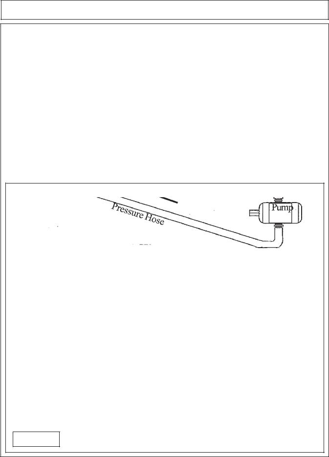
Flow Testing the Pump: (figure 1)
1.Use a Flow Meter that is rated to 6000 PSI and 60 GPM Minimum. This applies to the gear type pump and motor type only
2.the area around the hoses, motor, flow meter must be clean of all debris and dirt. NO contamination can be allowed to enter the system or its components. Make certain there is nothing in flow meter from previous use that will contaminate the hydraulic system, dirty and contamination in test equipment hoses and valves can cause a failure to occur.
3.Disconnect the hydraulic return hose from the motor. Connect the hoses to the flow meter as shown above, recheck all connections to make certain they are connected correctly and fittings have been check for tightness.
4.Completely open the pressure valve on the flow meter.
HYDRO 15 (Service Manual) 09/06
© 2006 Alamo Industrial |
Section 2 - 3 |
PUMP SERVICE & REPAIR
5.Record all the readings during the test. Start the system, run at 540 PTO speed (which will run pump at required speed) until the Oil temperature reaches at least 110° F. before starting test. Check the flow (GPM) at 0 psi. (or no load). Slowly close the pressure control valve (valve on flow meter) until the gauge pressure reaches 500 psi. and record the readings pressure, temperature and flow (GPM). Continues this at 500 psi increments until a maximum of 2000 psi.
6.If the flow rate is 85 % or greater of beginning flow rate at no load, the pump is serviceable and functioning within specifications.
CAUTION ! Stop tractor engine and discontinue testing if hydraoulic oil temperature exceeds 220° F. as temperatures above this could cause damage to components.
Example: Recorded test results |
|
|
|
||
PSI. |
GPM |
TEMP ° F. |
PSI. |
GPM |
TEMP ° F. |
0 |
____ |
________ |
500 |
____ |
________ |
1000 |
____ |
________ |
1500 |
____ |
________ |
2000 |
____ |
________ |
2500 |
____ |
________ |
3000 |
____ |
________ |
|
|
|
Shown Below is a Gear Pump Schematic
Figure 1
HYDRO 15 (Service Manual) 09/06 |
|
© 2006 Alamo Industrial |
Section 2 - 4 |
PUMP SERVICE & REPAIR |
|||||
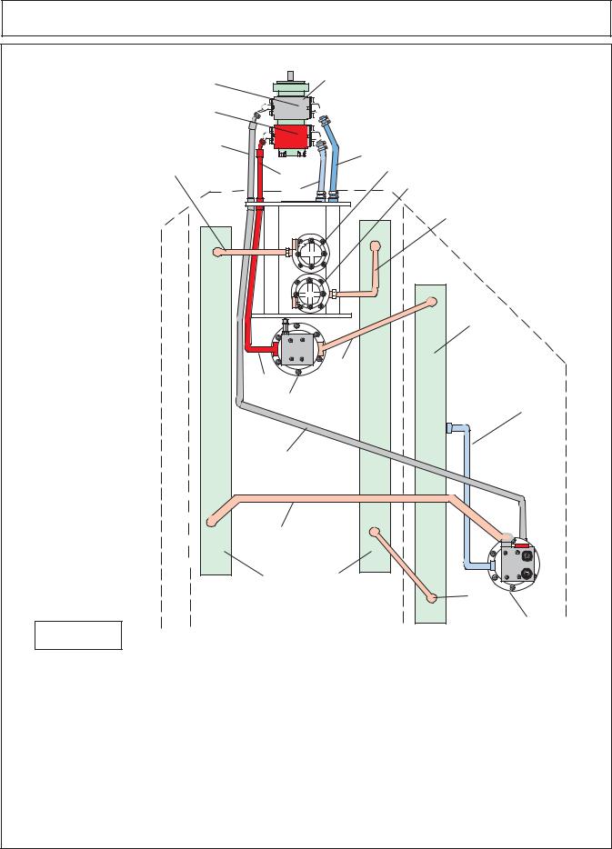
15 FT - PUMP & MOTOR HYDRAULIC SCHEMATIC |
|||||
Wing Supply (Front) Pump Half |
|
|
|
1 |
|
|
|
2 |
|
CAUTION ! NEVER Connect |
|
|
|
|
|
||
Center Supply (Rear) Pump Half |
|
|
2 |
|
|
|
|
12 |
|
Pump Pressure Line direct to cooling |
|
|
|
|
23 |
|
|
|
|
|
2 |
|
|
|
4 |
|
2 23 |
3 |
tubes, as it will damage the tubes. |
|
|
12 |
|
||
|
|
|
|
||
15 |
|
5 |
|
20 |
|
|
|
2 |
23 |
2 |
21 |
|
|
|
|||
|
|
23456789012345678901234567 |
|
||
|
|
1234567890123456 |
7 |
11 |
|
|
|
1234567890123456 |
7 |
||
|
|
1234567890123456 |
7 |
|
|
|
|
1234567890123456 |
7 |
|
|
|
|
1234567890123456 |
7 |
|
|
|
|
1234567890123456 |
7 |
|
|
|
|
1234567890123456 |
7 |
|
|
|
|
1234567890123456 |
7 |
|
|
|
|
1234567890123456 |
7 |
|
|
|
|
1234567890123456 |
7 |
|
|
|
|
1234567890123456 |
7 |
|
|
|
|
1234567890123456 |
7 |
|
|
|
|
1234567890123456 |
7 |
|
|
|
|
1234567890123456 |
7 |
|
|
|
|
1234567890123456 |
7 |
|
|
|
|
1234567890123456 |
7 |
|
|
|
|
1234567890123456 |
7 |
|
|
|
|
1234567890123456 |
7 |
|
|
|
|
1234567890123456 |
7 |
|
|
|
|
1234567890123456 |
7 |
|
|
|
|
1234567890123456 |
7 |
|
|
|
|
1234567890123456 |
7 |
|
|
|
|
1234567890123456 |
7 |
|
|
|
|
1234567890123456789012345 |
|
||
L-Wing |
|
|
|
|
R-Wing |
Cooling |
|
|
|
|
|
|
|
|
|
Cooling |
|
Tube |
|
|
|
|
|
|
|
|
9 |
Tube |
|
|
|
|
|
||
|
|
6 |
|
|
|
|
|
|
|
|
|
|
|
8 |
|
|
12 |
|
|
|
|
|
|
19 |
|
|
|
|
|
|
|
7 |
|
|
|
18 |
|
|
|
|
|
|
|
14 |
|
|
|
21 |
Center (LH & RH) |
10 |
CoolingTubes |
20
13
Figure 2
Item Description
1Tandem Pump Asy
2Suction (Tank to Wing Pump)
3Suction (Tank to Center Pump)
4Pressure (Pump to Bulk Head Fitting)
5Pressure (Pump to Bulk Head Fitting)
6Pressure (Bulk Head Fititng to Center Motor)
7Pressure (Bulk Head Fitting to Wing Motors)
8Motor Asy (Center Sction Motor)
9Return (Center Motor to Wing CoolingTube)
10Return (Wing Tube to Center Cooling Tube)
11Return (Center Coolingg Tube to Fiter / Tank)
Item Description
12Case Drain (R- Wing Motor to Cooling Tube)
13Wing Motor Asy (R- Wing)
14Return / Pressure (f/ R-Wing to L-Wing Motor)
15Return (Center Cooling Tube to Filter / Tank)
16Return Filter & Gauge (Wing Motors Return)
17Return Filter & Gauge (Center Motor Return)
18Return (L-Wing Motor to Cooling Tube)
19Case Drain (L-Wing Motor to Cooling Tube)
20Wing Motor Asy (L-Wing)
21Return (L-Wing Tube to Center Cooling Tube)
HYDRO 15 (Service Manual) 09/06
© 2006 Alamo Industrial |
Section 2 - 5 |
PUMP SERVICE & REPAIR |
|
10 FT - PUMP & MOTOR HYDRAULIC SCHEMATIC |
|
Wing Supply (Front) Pump Half |
1 |
Center Supply (Rear) Pump Half
4
15
Figure 3
|
|
2 |
|
|
|
|
2 |
2 |
|
|
|
|
|
123 |
|
|
|
|
|
23 |
|
|
|
|
|
2 |
|
CAUTION ! |
NEVER |
|
2 |
2 |
|
||
|
|
2 23 |
3 16 |
Connect Pump Pressure Line |
|
|
|
12 |
|||
|
5 |
|
|||
|
|
|
|||
|
|
17 |
direct to cooling tubes, as it |
||
|
2 |
12 |
will damage the tubes. |
||
|
23 |
|
|
||
|
|
12 |
23 |
|
|
12345678901234567890123456 |
|
|
|||
12345678901234567 |
7 |
11 |
|
||
1 |
234567890123456 |
|
|||
1 |
234567890123456 |
7 |
|
|
|
1234567890123456 |
7 |
|
|
||
1234567890123456 |
7 |
|
|
||
1234567890123456 |
7 |
|
|
||
1234567890123456 |
7 |
|
|
||
1234567890123456 |
7 |
|
|
||
1 |
234567890123456 |
7 |
|
|
|
1234567890123456 |
7 |
|
|
||
1234567890123456 |
7 |
|
|
||
1234567890123456 |
7 |
|
|
||
1234567890123456 |
7 |
|
|
||
1234567890123456 |
7 |
|
|
||
1234567890123456 |
7 |
|
|
||
1234567890123456 |
7 |
|
|
||
1234567890123456 |
7 |
|
|
||
1 |
234567890123456 |
7 |
|
|
|
1234567890123456 |
7 |
|
|
||
1234567890123456 |
7 |
|
|
||
1234567890123456 |
7 |
|
|
||
1234567890123456 |
7 |
|
|
||
1234567890123456 |
7 |
|
|
||
|
2345678901234567 |
|
|
|
|
2345678901234567890123456 |
|
|
|||
|
|
|
|
R-Wing |
|
|
|
|
|
Cooling |
|
|
|
|
9 |
Tube |
|
6 |
|
|
|
||
|
|
|
|
||
|
8 |
|
|
12 |
|
|
|
|
|
|
|
|
7 |
|
|
|
|
|
14 |
|
|
|
|
Center (LH & RH) |
10 |
CoolingTubes |
13
Item |
Description |
Item |
Description |
1 |
Tandem Pump Asy |
12 |
Case Drain (R- Wing Motor to Cooling Tube) |
2 |
Suction (Tank to Wing Pump) |
13 |
Wing Motor Asy (R- Wing) |
3 |
Suction (Tank to Center Pump) |
14 |
Return (R-Wing Motor to Cooling Tube) |
4 |
Pressure (Wing Pump to Bulk Head Fitting) |
15 |
Return (Center Cooling Tube to Filter / Tank) |
5 |
Pressure (Center Pump to Bulk Head Fitting) |
16 |
Return Filter & Gauge (Wing Motor Return) |
6 |
Pressure (Bulk Head Fititng to Center Motor) |
17 |
Return Filter & Gauge (Center Motor Return) |
7Pressure (Bulk Head Fitting to Wing Motor)
8Motor Asy (Center Sction Motor)
9Return (Center Motor to Wing CoolingTube)
10Return (Wing Tube to Center Cooling Tube)
11Return (Center Coolingg Tube to Fiter / Tank)
HYDRO 15 (Service Manual) 09/06 |
|
© 2006 Alamo Industrial |
Section 2 - 6 |
PUMP SERVICE & REPAIR
Recommended Tools: |
Bushing Puller: The bushings in the pump may be |
|
|
Listed below are some of the toolds that |
removed from tier bores, using blind hole collet-type bushing |
are recommended for the dis-assembly and re- |
pullers similar to those manufactured by Owatonna Tool Co. The |
|
assembly of the pump for the HYDRO 15 Mower. |
Table below illustrates the modification necessary to adapt the |
|
1. |
Arbor Press |
OTC collets to this task. Equivalent pullers from other suppliers |
2. |
Awl |
may be modified in a similar fashion. |
3. |
1-1/2" Dia steel ball |
|
|
|
|
|
|
|
|
Make |
|
4. |
Bearing Puller (Owaonna Tool Co. |
Pump |
|
A |
|
|
B |
|
C |
|
|
|
|
|
|
f/ OTC |
|
||||||
|
MD-956orequivalent) |
|
|
|
|
|
|
|
Collet No. |
|
|
5. |
Bushing Remover Tool (figure 4) |
|
|
|
|
|
|
|
|
||
Wing Supply |
.980 |
|
.875 |
.100 |
33863 |
|
|||||
6. |
Clean lintless Cloth |
|
|
||||||||
Pump |
|
.970 |
|
|
Ref |
.090 |
|
|
|||
7. |
Deburing Tool (an old file with cutting |
Center Supply |
1.382 |
1.260 |
.100 |
33865 |
|
||||
|
teeth ground off) |
|
|||||||||
|
Pump |
|
1.372 |
1.250 |
.120 |
|
|||||
8. |
Machinest Hammer |
|
|
|
|||||||
|
|
|
|
|
|
|
|
|
|
||
9. |
Soft Hammer |
|
|
C |
|
|
|
.015 R Maximum |
|
||
10. |
Permatex Aviation Form-A-Gasket.™ |
|
|
|
|
|
|
|
|
|
|
|
(No. 3 non hardening sealant or equal) |
Figure 4 |
|
A |
B |
|
|
|
|
|
|
11. |
Medium Grit Carborundurn Stone. |
|
|
|
|
|
|
|
|||
|
|
|
|
|
|
|
|
|
|
||
12. |
Seal removal Tool (figure 6) |
|
|
|
|
|
|
|
|
|
|
13. |
Oil and Grease |
|
|
|
|
|
A |
|
|
|
|
14. |
Snap Ring Pliers |
Bushing Installation |
|
|
|
|
|
|
Surface |
||
|
|
|
|
|
B |
|
|||||
15. |
Prick Punch |
|
|
|
|
|
|
Finish |
|||
Tool A.I.S.I 8620 |
|
|
|
|
|
|
|||||
16. |
Bushing Installation Tool (figure 5). |
|
|
|
|
|
|
|
32 |
|
|
Bearing Qaulity |
|
.06 |
|
|
|
.06 |
|
||||
17. |
Scale (1/32" or 1/64" graduations) |
|
|
|
|
|
|
||||
Steel Heat treated |
|
|
|
|
|
|
|
||||
|
|
|
|
|
|
|
|
|
|||
18. |
Small Screw Driver |
|
|
|
|
|
|
|
|
|
|
|
|
|
|
|
|
|
|
|
|
||
19. |
Torque Wrench (in. lbs & ft lbs) |
|
|
|
|
|
|
|
|
|
|
20. |
Vise with 6" minimum opening |
|
|
|
|
|
|
|
|
C |
D |
21. |
Bar for Lip Seal Installation |
|
|
|
|
|
|
|
|
||
|
|
|
|
|
|
|
|
30° |
|
||
|
For Front (Wing Supply) Pump |
|
|
|
|
|
|
|
|
|
|
|
|
|
|
|
|
|
|
|
|
|
|
|
use 1-3/4" dia X 2" Bar |
Figure 5 |
|
|
|
|
|
|
|
|
|
|
For Rear (Center Supply) Pump |
|
|
30° |
|
|
|
|
|||
|
use 2-1/2" dia X 2" Bar |
|
|
|
Grind Relief Allowable |
||||||
|
|
|
|
|
|
|
|||||
22. |
Special Steel Sleeve (figure 7) |
Pump |
A |
|
B |
|
|
C dia. |
D dia. |
||
|
Seal Removal Tool: Easily |
|
|
|
|||||||
|
Wing Supply |
|
|
|
|
|
|
+ .000 |
|
|
|
|
made from old screw driver. |
3.00 |
1.47 |
|
1.054 |
1.250 |
|
||||
|
Pump |
|
- .002 |
|
|||||||
|
Heat the tip and bend as |
|
|
||||||||
|
Center Supply |
|
|
|
|
|
|
+ .000 |
|
|
|
|
shown. Grind the tip to fit the |
3.00 |
1.73 |
1.492 |
1.750 |
||||||
|
notch behind the shaft seal. |
Pump |
|
|
|
- .002 |
|
|
|||
|
|
|
|
|
|
|
|
|
|
|
|
|
|
|
|
|
|
Special Steel Sleeve: The special steel sleeve is used to insert the |
|
||||||||
|
|
|
Figure 6 |
|
1/4" |
|
|
|
|
||||||||||||||||||
|
|
|
|
|
|
|
|
|
|
|
drive shaft through the lip seal without damage and can be made |
|
|||||||||||||||
|
|
|
|
|
|||||||||||||||||||||||
|
|
|
|
|
|
|
|
|
|
|
|
|
|
|
|
|
|
from bar stock. For the center supply pump use a 1-1/8" to 1-1/4" |
|
||||||||
|
|
|
|
|
|
|
|
|
|
|
|
|
|
|
|||||||||||||
|
|
|
|
|
|
|
|
|
|
|
|
|
|
|
|
|
|
diaX4-5/8"bar.Forwingsupplypumpusea1-1/2"diaX4-5/8"bar. |
|
||||||||
|
|
C Rad 1/4" Hole Drill through |
|
|
|
The drawing and cgart give details for making this special tool. |
|
||||||||||||||||||||
|
|
|
|
|
|
|
|
|
|
|
|
|
|
|
|
|
|
|
|
|
|
||||||
|
|
|
|
|
|
|
|
|
|
Pump |
|
A |
|
B |
C Rad |
D Rad |
E dia. |
F°Chamfer |
|
|
|
||||||
|
|
|
|
|
|
|
|
|
|
||||||||||||||||||
|
|
|
|
|
|
|
|
|
|
|
|
|
|
|
|
|
|
|
|
|
|
|
|||||
|
|
|
|
|
|
|
|
|
Wing Supply |
3-3/8" |
|
4-1/2" |
9/16" |
1.065 + .000 |
1.002 + .002 |
.015" X 45° |
|
|
|
||||||||
|
|
|
|
|
|
|
|
|
|
|
|
||||||||||||||||
|
|
|
|
|
|
|
|
|
|
||||||||||||||||||
|
|
|
|
|
|
|
B |
|
Pump |
|
|
|
|
|
|
|
- .002 |
- .000 |
|
|
|
|
|||||
|
|
|
|
|
|
|
|
|
|
|
|
|
|
|
|
|
|
||||||||||
|
|
|
|
|
|
|
A |
Center Supply |
3-3/8" |
|
4-1/2" |
9/16" |
1.377 + .000 |
1.250 + .002 |
.015" X 60° |
|
|
||||||||||
|
|
|
|
|
|
|
|
||||||||||||||||||||
|
|
|
|
|
|
|
|
|
|
||||||||||||||||||
|
|
F° |
|
|
|
E |
|
Pump |
|
|
|
|
|
|
|
- .002 |
- .000 |
|
|
|
|
||||||
|
|
|
|
|
|
|
|
|
|
|
|
|
|
|
|
||||||||||||
|
|
|
|
|
|
|
|
Figure 7 |
|
|
|
All external surfaces MUST be free of scratches and burrs |
|
||||||||||||||
|
|
|
|
|
|
|
|
|
|
|
|
||||||||||||||||
|
|
|
|
|
|
|
|
D |
|
|
|
|
|
||||||||||||||
|
|
|
|
|
|
|
|
|
|
|
|
|
|
|
|
|
|
|
|
|
|
|
|
|
|
|
|
|
|
|
|
|
|
|
|
|
|
|
|
|
|
|
|
|
|
|
|
|
|
|
|
|
|
|
|
HYDRO 15 (Service Manual) 09/06 |
|
|
|
|
|
|
|
|
|
|
|
|
|
||||||||||||||
© 2006 Alamo Industrial |
|
|
|
|
|
|
|
|
|
|
Section 2 - 7 |
|
|
|
|
|
|
||||||||||

PUMP SERVICE & REPAIR
Pump Cleaning & Removal:
1. Clean Pump, Hoses and all connections before disconnecting any components from the pump. This will keep contamination from getting into system. Figure 8 shows the pump and hoses connected to the mower (this mower is new, clean and un-used) with the pump sitting on the ground, if the hoses are to be dis-connected, the pump should mounted up and above the hydraulic tank (on work bench, hoist, etc.). What ever the technician decides to mount pump on. Some type of drain pan will be required to catch the oil that will drain out when hoses are dis-connected. The hoses will need to be capped (plugged) after removal being disconnected. If cap is not leak proof then hoses must remain elevated above hydraulic tank to prevent oil leakage from hose fittings. Figure 9 shows how the
hoses are connected. Hoses are connected with 4 bolt split Figure 8 flange kits (1-1/2" on suction side &1" on pressure side)
3
1
Figure 9
7
Tandem Mounted Pump
6
5
|
|
4 |
|
|
2 |
Item |
Qty |
Description |
1 |
1 |
Pump Assembly (Tandem Pump) |
2 |
2 |
Split Flance Kit, (1" Flange) |
|
1 |
O-Ring (for 1" Flange) (Qty Each Kit) |
|
4 |
Bolt, Hex Head, (Qty Each Kit) |
|
4 |
Lockwasher (Qty Each Kit) |
3 |
2 |
Split Flance Kit, (1-1/2" Flange) |
|
1 |
O-Ring (for 1" Flange) (Qty Each Kit) |
|
4 |
Bolt, Hex Head, (Qty Each Kit) |
|
4 |
Lockwasher (Qty Each Kit) |
4 |
1 |
Hose Asy, 1" Hose & Flange (Pressure to Wing Motors) |
5 |
1 |
Hose Asy, 1" Hose & Flange (Pressure to Center Motor) |
6 |
1 |
Hose Asy, 1-1/2" Hose & Flange. (Suction Hose for Center Motor |
7 |
1 |
Hose Asy, 1-1/2" Hose & Flange. (Suction Hose for Wing Motor) |
HYDRO 15 (Service Manual) 09/06 |
|
© 2006 Alamo Industrial |
Section 2 - 8 |
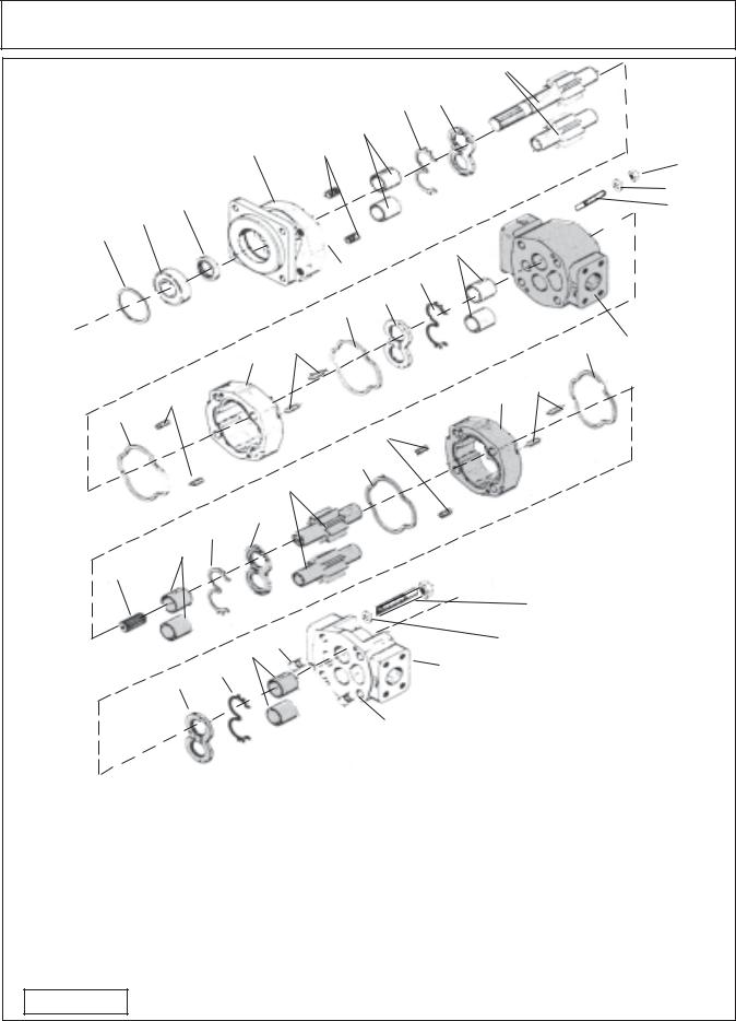
PUMP SERVICE & REPAIR
|
|
|
|
|
7 |
8 |
|
|
|
9 |
|
|
|
|
|
|
Pump Component Schematic |
|
|
|
|
|
|
|
|
|
|
|
|||||
|
|
|
|
6 |
|
|
|
|
|
|
|
|
|
|
|
|
|
|
|
4 |
5 |
|
|
|
|
|
|
|
|
|
|
|
20 |
|
|
|
|
|
|
|
|
|
|
|
|
|
|
|
|
|
|
|
2 |
3 |
|
|
|
|
|
|
(outlet |
side) |
|
19 |
|||
|
|
|
|
|
|
|
|
|
|
|
|
18 |
||||
|
1 |
|
|
|
|
|
side |
|
|
|
|
|||||
|
|
|
|
|
this |
|
|
|
|
|
|
|
||||
|
|
|
|
|
|
|
|
|
|
|
|
|
|
|||
|
|
|
|
|
install |
6 |
|
|
|
|
|
|
|
|
||
|
|
|
|
|
5 |
|
|
|
|
|
|
|
|
|
||
|
|
|
|
Item |
7 |
|
|
|
|
|
|
|
|
|||
|
|
|
|
|
|
|
|
|
|
|
|
|
|
|||
|
|
|
|
|
|
|
|
|
|
|
|
|
|
|
|
|
|
|
|
|
10 |
8 |
|
|
|
|
|
|
|
|
|
|
|
|
|
|
|
|
|
|
|
|
|
|
|
|
|
|
|
|
|
|
|
12 |
11 |
|
|
|
|
|
|
|
|
|
10 |
13 |
|
|
|
|
|
|
|
|
|
|
|
|
|
|
|
|
||
|
|
|
|
|
|
|
|
|
|
|
|
|
|
|
|
|
|
|
|
11 |
|
|
|
|
|
|
16 |
|
|
11 |
|
|
|
|
|
|
|
|
|
|
|
|
|
|
|
|
|
|||
|
10 |
|
|
|
|
|
|
|
|
|
|
|
|
|
|
|
|
|
|
|
10 |
11 |
|
|
|
|
|
|
|
|
|
|
|
|
|
|
|
|
|
|
|
|
|
|
|
|
|
|
|
|
|
|
|
15 |
|
|
|
|
|
|
|
|
|
|
|
|
|
|
|
|
8 |
|
|
|
|
|
|
|
|
|
|
|
|
|
|
|
|
7 |
|
|
|
|
|
|
|
|
|
|
|
|
|
|
|
|
6 |
|
|
|
|
|
|
|
|
|
|
|
|
|
|
14 |
|
|
|
|
|
|
|
|
|
|
|
|
|
|
|
|
|
|
|
|
|
|
|
|
|
|
|
|
|
22 |
|
|
|
|
|
5 |
|
|
|
|
|
|
|
21 |
|
|
|
||
|
|
|
7 6 |
|
|
|
|
17 |
|
|
|
|
|
side) |
|
|
|
|
|
|
|
|
|
|
|
side |
(outlet |
|
|
||||
|
|
|
8 |
|
|
|
|
|
this |
|
|
|
|
|||
|
|
|
|
|
|
|
|
|
|
|
|
|
|
|||
|
|
|
|
|
|
|
|
|
|
|
|
|
|
|
||
|
|
|
|
|
|
install |
|
|
|
|
|
|
|
|
||
|
|
|
|
|
|
5 |
|
|
|
|
|
|
|
|
|
|
|
|
|
|
|
Item |
|
|
|
|
|
|
|
|
|
|
|
Item |
Qty |
|
Description |
|
|
Item |
|
|
Qty |
|
|
Description |
|
|
||
1 |
1 |
|
Snap Ring |
|
|
11 |
|
|
8 |
|
|
|
Dowel Pins |
|
|
|
2 |
1 |
|
Bearing, Outboard |
|
|
12 |
|
|
1 |
|
|
|
Gear Housing |
|
|
|
3 |
1 |
|
Seal, Input |
|
|
13 |
|
|
1 |
|
|
|
BearingCarrier |
|
||
4 |
1 |
|
Shaft End Cover |
|
|
14 |
|
|
1 |
|
|
|
Connecting Shaft |
|
||
5 |
1 |
|
Plug |
|
|
15 |
|
|
1 |
|
|
|
Gear Set (Matched) |
|
||
6 |
8 |
|
Bushings |
|
|
16 |
|
|
1 |
|
|
|
Gear Housing |
|
|
|
7 |
4 |
|
Channel Seal |
|
|
17 |
|
|
1 |
|
|
|
Port End Cover |
|
||
8 |
4 |
|
Thrust Plate |
|
|
18 |
|
|
4 |
|
|
|
Studs |
|
|
|
9 |
1 |
|
Integral Drive Shaft and Gear Set |
|
19 |
|
|
4 |
|
|
|
Lockwasher |
|
|
||
10 |
4 |
|
Gasket Seal |
|
|
20 |
|
|
4 |
|
|
|
Nuts |
|
|
|
|
|
|
|
|
|
21 |
|
|
4 |
|
|
|
Lockwasher |
|
|
|
Figure 10 |
|
|
|
|
22 |
|
|
4 |
|
|
|
Bolt |
|
|
||
HYDRO 15 (Service Manual) 09/06
© 2006 Alamo Industrial |
Section 2 - 9 |

PUMP SERVICE & REPAIR
IMPORTANT !
Mark all Sections of Pump with a Number (or) Symbols that will serve as a guide to all sections being re-installed the same way they were removed. Example: if the numbers (marks) do not line up (1, 2, 3, 4 & 5) as they were marked, the pump is not being assembled correctly. Check this all through the assembly process. 
1-1/2" Split Flange |
|
1" Split Flange |
|
Suction (Inlet) Side |
|
Pressure (outlet) Side |
|
|
5 |
Port End Cover |
|
|
|
||
Service Technician |
4 |
Rear Gear Housing |
|
Makes Alignment |
|||
|
|||
Marks Here |
|
|
|
1-1/2" Split Flange |
|
1" Split Flange |
|
|
Pressure (outlet) Side |
||
Suction (Inlet) Side |
|
||
3 |
|
||
|
|
||
|
|
Port Bearing Housing |
|
|
2 |
Front Gear Housing |
|
|
|
Service Technician Makes Alignment
Marks Here
Shaft End Cover
1
|
|
|
See Figure 10 |
|
|
|
|
|
|
|
|
|
12345678 |
|
|
|
12345678 |
|
|
|
12345678 |
|
|
|
12345678 |
|
|
|
12345678 |
|
for Compo- |
|
12345678 |
|
|
|
12345678 |
|
|
|
12345678 |
|
|
|
12345678 |
|
nent Item |
|
12345678 |
|
|
|
12345678 |
|
|
|
12345678 |
|
|
|
12345678 |
|
|
12345678
Number
Speed Changer
|
& |
|
Figure 10A |
||
Tractor PTO |
||
|
HYDRO 15 (Service Manual) 09/06 |
|
© 2006 Alamo Industrial |
Section 2 - 10 |

PUMP SERVICE & REPAIR
Pump Dis-Assembly CAUTION! :
Important information - read before dis-assembly:
1.If prying off sections becomes necessary, take extreme care not to mar or damage machined surfaces. Excessive force while prying can result in misalignment and seriously damage parts.
2.If parts are difficult to come apart during dis-assembly, tap gently with a soft hammer (never use an iron hammer).
3.Gears are closely matched, therefore they must be kept together as sets when removed from the pump. Handle gears with care to avoid damage to journals or teeth. Avoid touching gear journals.
4.Never hammer bushing into bores: always use an arbor press.
Pump Dis-Assembly:
1.Place the pump in a vise with the drive shaft pointing down. Caution DO NOT grip on or near any machined surfaces of pump during assembly or dis-assembly. Mark all sections of the pump (figure 10A) , these marks must be done in a manner that will not wash off and these marks are to identify the orientation of the component of the pump later for re-assembly. It is recommended that marks be done with metal stamps that will mark components for correct assembly order for & during re-assembly. This is very important as if any of the sections of pump are installed in the wrongdirectionitcould damage pumpwhenre-assembledorwhen pump is engaged during operation (figure 11).
2.Use a socket Wrench or Boxed end wrenches (Air impact wrenches are not recommended for dis-assembly). Remove the four hex bolts and washers (figure 10 item 19 & 20) , This will allow for the removal of the outward half of the pump. The inward section is still connected together with the studs and nuts which will be
removed in a later step. Inspect the bolts for thread condition. If bad threads on bolts most likely the threads in that hole are bad, mark the hole so it can be check later.
Figure 11
Figure 12
Figure 13
Figure 14
Figure 15
HYDRO 15 (Service Manual) 09/06
© 2006 Alamo Industrial |
Section 2 - 11 |
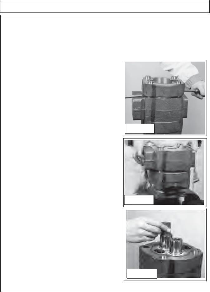
PUMP SERVICE & REPAIR
3.Lift the first port end cover (figure 10 item 17), if prying is necessary, be careful not to damage the machined surfaces. Dowel pins (figure 10 item 11) will remain in either the port end cover or gear housing. This will be OK because the components must be re-assembled in the same direction and orientation as removed. If one or more of the components are to be replaced as parts then it may require that the dowel pins be removed (figure13).
4.Remove the thrust plate (figure 10 item 8). Make a note how this was removed, there is a smooth side and there is a grooved side. The smooth side will always face the gears, the grooved side will be for the channel
seal (figure 10 item 7). Inspect the thrust plate for damage or wear at this time(see wear tolerance chart for pump and motors in this section), this will help in looking for other wear or damage to other components and also enable you to start making a list of components that need replacing.
5.Carefullyremovethedrivegearandthedrivengear(figure10 item 15). Avoid tapping the gear teeth together or against other hardened surfaces (figure 15), Keep these gears together because they are a matched set. Examine the gears for wear and/or damage. Note the dowels (figure 15) that are in the gear housing, sometimes these will come out and be in the end cover or they may stay in the gear housing. It will be OK as long as the same components are to be reassembled, but if some components are to be replaced and some are not then these dowel pins will have to be re-moved and re-inserted.
6.Remove the outer gear housing (figure 10 item 16). Lift the outer gear housing (figure 16) up, if prying is necessary take care not to damage machined surface. Examine gear housing for wear and /or damage. (See wear tolerance chart for pump and motors in this section). When the gear housing is removed there will be another thrust plate and channel seal (figure 10 item 7 & 8) that was under the gears, sometimes this thrust plate will come out with the gears.
7.Carefully lift or pry the bearing carrier (figure 10 item 13) off carefully to avoid damage to carrier (figure 17). The dowel pins will remain in the bearing carrier housing or the gear housing, it will not require that they be removed unless the housing is to be replaced and then only to arrange the dowel pins order so the components will fit together.
8.Remove the connecting shaft (figure 10 item 14) as shown (figure 18) by pulling it up out of the drive gear shaft splines. Inspect the shaft for wear and /or damage. Inspect the end of the drive gear. Remove the thrust plate, note the thrust plate will have the channel seal in it (figure 10 item 7 & 8). Note the smooth side of thrust plate always goes toward the gear. Care fully remove the drive gear and the driven gear (figure 10 item 9). Avoidtapping thegearteethtogetheroragainst other hardened surfaces (figure 18), pull the drive gear straight up. The drive gear has the splined shaft on the other end and care must be taken not to hit the splined shaft against sides and damaging them.Keep these gears together because they are a matched set. Examine the gears for wear and / or damage
Figure 16
Figure 17
Figure 18
HYDRO 15 (Service Manual) 09/06 |
|
© 2006 Alamo Industrial |
Section 2 - 12 |

PUMP SERVICE & REPAIR
9.Lift or pry off the first section of gear housing (figure 10 item 12). Be careful not to damage machined surfaces (figure 19). Inspect the gear housing (See wear tolerance chart for pump and motors in this section). for wear and / or damage.
10.Inspect all of the bushings for scoring or discoloration (figure 10 item 6 qty 8) in the port end cap, bearing carrier (both sides) and the shaft end cover. If they need to be replaced use a bushing puller as shown (figure 4 recommended tools list). Remove the bushings with care not to damage housings(figure 20).
11.Remove shaft end cover (figure 10 item 4) from vice and turn it 180° over and re-insert it into vice. Using snap ring pliers remove the snap ring (figure 10 item 1) as shown (figure 21).
12.Remove the shaft bearing (figure 10 item 2) using a bearing puller (figure 22). Make certain to use the correct size bearing puller and that puller is inserted straight.
13.Remove shaft end cover (figure 10 item 4) from vice and turn it 180° over and re-insert it into vice. Remove the double lip seal by inserting the special seal removal tool (see figure 6 recommended tools). Make note of which way seal is removed. Inspect
the shaft end cover seal seat area (figure 23).
14. Inspect all the components that have been removed (review steps 1 through 13). There are 4 gasket seals (figure 10 item 10) that are installed, one on each side of the gear housing. Make certain the gasket seal have been removed and the gasket groovesareclean.Washandcleanallthe components,DONOT use any material that will leave lint on components, it 's best to air dry the components. Use extreme caution when cleaning gear sets, DO NOT use any abrasive materials at all and DO NOT bang the gears together. Keep the gears in the same sets as they were remove as they are a matched set and must remain as a set. (See next two pages for wear identification).
Figure 19
Figure 20
Figure 21
Figure 22
Figure 23
HYDRO 15 (Service Manual) 09/06
© 2006 Alamo Industrial |
Section 2 - 13 |
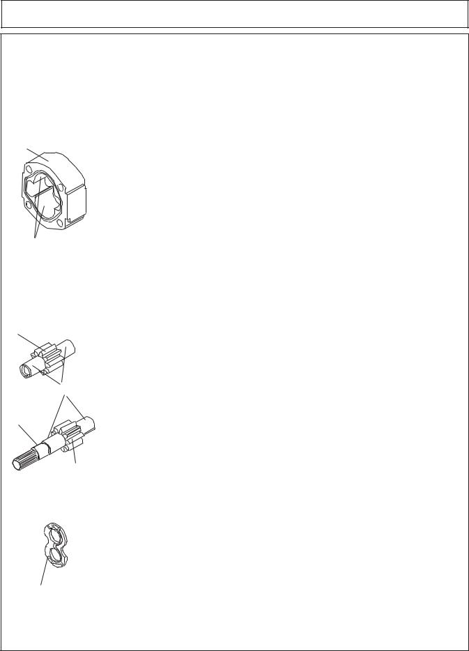
PUMP SERVICE & REPAIR
Wear Tolerance for Pump & Motor:
This is suggested Wear Tolerance to Keep Assemblies operating as efficient as
possible, Not Complete failure rate. Your Pumps and/or motors may not be exact same as discussed here.
Gear Housing
Cut-Out Area
Gear Wear Area
Gear Housing: Gear type Pump and Motor
Wear in excess of .007" cut-out necessitates replacement of the Gear Housing. Place a straight edge across the Bore in the cut out area. If you can slip a .007" feeler gage under the straight edge in the cutout area. Replace the Gear Housing.
Pressure pushes the Gears against the Housing on the Low-Pressure side. As the Hubs and Bushings wear, the cutout becomes more pronounced. Excessive cutout wear in short period of time indicates excessive pressure or Oil contamination. If the relief Valve Settings are within prescribed limits check for shock pressures or tampering. Withdraw Oil Samples and check it and tank for dirt. Where cut-out is moderate, 0.007" or less, gear housing is in good enough condition and may be reused, understand if you are at 0.007" you are at the upper limits and will not be at peak performance. A pump should always produce at least 85% efficiency (Example: if your Pump is rated at 37 GPM it should produce at least 32 GPM).
Gear Teeth
Gear Hubs
Seal
Area
 Gear Teeth
Splines
Thrust Plate
Gears:
Any scoring on Gear Hubs necessitates Replacement. Scoring, Grooving or Burring of Outside diameter of Teeth requires replacement. Nicking, Grooving or Fretting of Teeth surfaces also necessitates replacement.
Drive Shaft: (with Built on Gear)
If Gear Teeth and Gear Hubs are OK, Inspect Splines on input end (OD) of Shaft and the Splines (ID) Output) Coupler End (Tandem Pump) for condition and Wear.
Inspect Wear or damage to Seal Wear Area. If damage at Seal are check for contamination. Note: Some Pumps and/or Motors may have Keyway or Splines. Either will have to be inspected for condition. If Damage in any of these area the Shaft / Gear will have to be replaced.
Thrust Plate:
The Thrust Plate Seals the Gear Section at the sides of the Gears. Wear will allow internal slippage, which is Oil bypassing within the pump. The Pump and Motor Thrust Plates are different even though they may look very similar. They are built different. They will not interchange.
A Maximum of 0.002" wear is allowable. Replace Thrust Plates if they are scored, eroded or pitted. Wear can be checked usually by comparing thickness at outer edges with thickness at Gear contact area.
1.Check center of Thrust Plates where the Gears mesh. Erosion here indicates Oil contamination.
2.Pitted Thrust Plates indicate cavitation or Oil aeration.
3.Discolored Thrust Plates indicate overheating, probably insufficient Oil.
HYDRO 15 (Service Manual) 09/06 |
|
© 2006 Alamo Industrial |
Section 2 - 14 |
 Loading...