

Page 1

LCT TV
Service Manual
Page 2

-2 -
MODEL:
LCT-20CVST
Model No.: LCT-20CVST
Version: 1.0
Page 3

-3 -
CONTENTS
SPECIFICATION..................................................................................................................................... 4
ADJUSTMENT SPECIFICATION.......................................................................................................... 8
PCB ASSEMBLY FUNCTIONAL DESCRIPTION ............................................................................. 11
BLOCK DIAGRAM ..............................................................................................................................16
IMPORTANT IC LIST........................................................................................................................... 17
TROUBLE SHOOTING ........................................................................................................................ 18
EXPLODED VIEW................................................................................................................................ 22
PART LIST............................................................................................................................................. 30
CIRCUIT DIAGRAM............................................................................................................................ 32
Model No.: LCT-20CVST
Version: 1.0
Page 4
-4 -
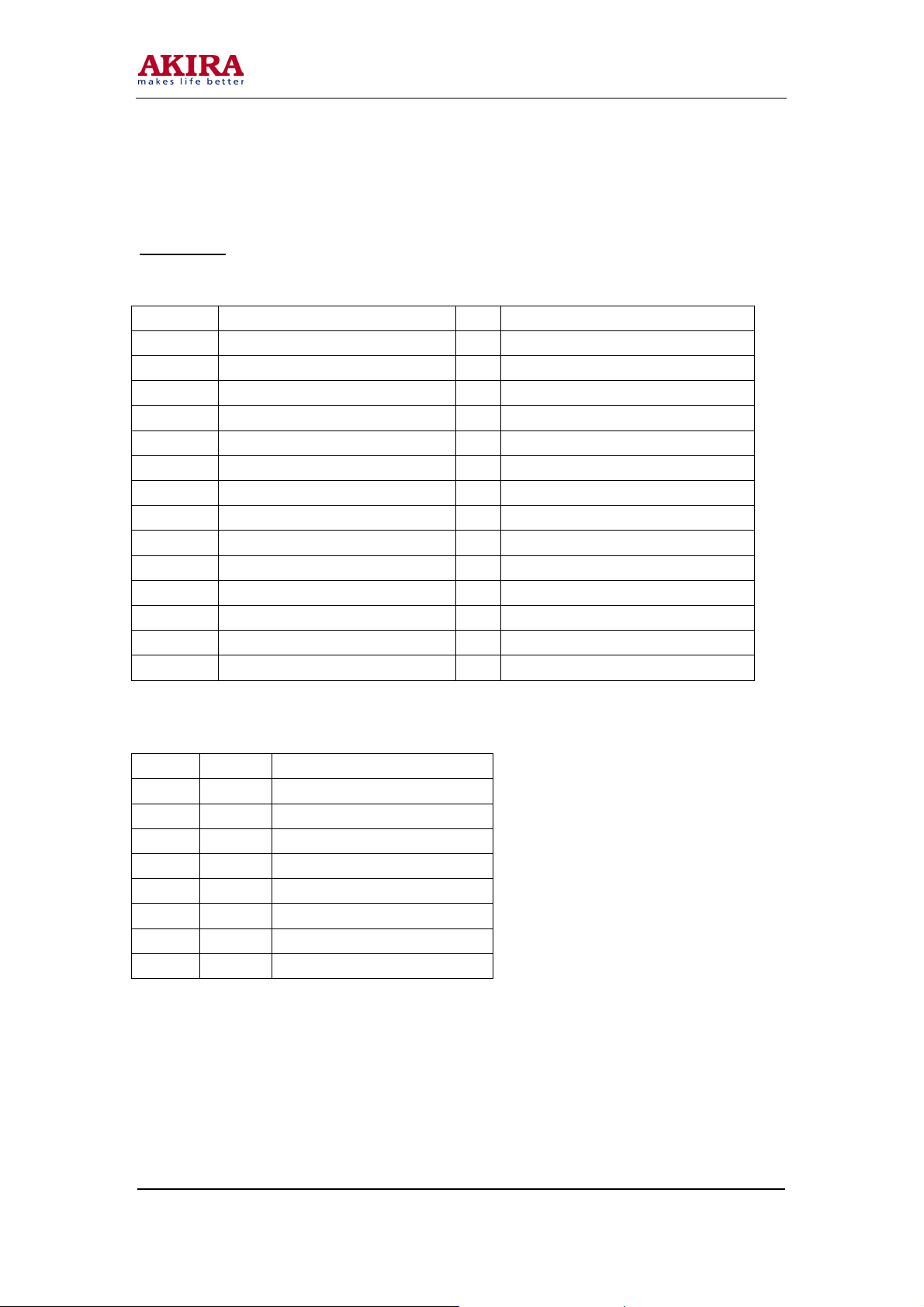
SPECIFICATION
LCD Panel
LG-Philips LCD Panel : LC201V02-A3
Active Screen Size : 20.1 inches (584.40m/m) diagonal
Outline Dimension : 432(H) x 331.5(V) x 25.0(D)mm(Typ)
Pixel Pitch : 0.6375mm x 0.6375 x RGB
Pixel Format : 640 horiz. By 480 Vert. Pixels RGB strip arrangement
Color Depth : 8bit, 16.7M Colors
Luminance, White : 450 cd/
Response Time : 25msec (Rise 13ms + Decay 12ms)
Viewing Angle : R/L 176 Degree, U/D 176 Degree
Backlight Assembly : 6 CCFL
Contrast Ratio : 350 : 1
In/Out Jack
Power Input : AC100 ~ 240V 50 ~ 60Hz
Antenna Input : 75 Ohm Unbalanced Coaxial Cable
PC Input : 15 Pin D-sub Jack(Female Type) – RGB Analog Input, Included Main Board
PC Audio Input : Phone Jack(Stereo) – From PC, Included Main Board
Video & Audio In/Out – Included Sub Board
Video Input 1(Composite RCA 3Pin, Included Audio 2Pin)
-
Video Input 2(Composite RCA 3Pin, Included Audio 2Pin)
-
DVD Input (Y Cb Cr, RCA 3Pin)
-
S-Video Input
-
EURO Scart Jack
-
Headphone Output (Phone Jack, Stereo)
-
A/V Output (Scart Jack)
-
Model No.: LCT-20CVST
Version: 1.0
Page 5
-5 -
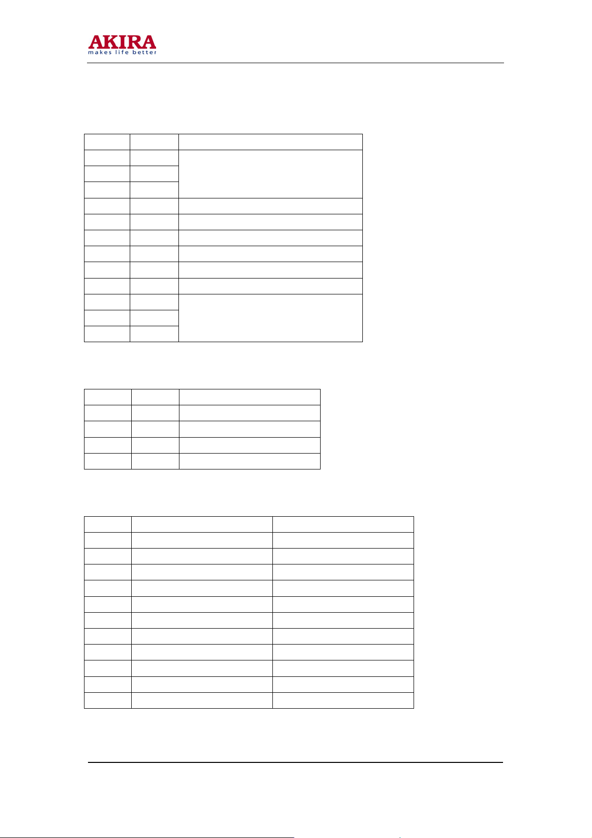
User Interface
7 Panel Key
Power , Menu , Select , Vol Up , Vol Down , CH Up , CH Down
3 Color LED
Red : Stand by Condition
Green : Power On Condition
Yellow : SLEEP TIME On Condition
Remocon Receiver
Remocon (42Key )
On Screen Display
Control using OSD
OSD Language : English, Arab
Plug & Play : DDC - 1/2B
Factory Mode
Mode for controlling the adjustment item & Panel Option in mass production
Electrical specification
In /Out Items Sub Items Specification
Video 1, 2 Level 1±0.1p_p (75Ω)
PC
INPUT
OUTPUT
POWER
Model No.: LCT-20CVST
Version: 1.0
DVD Level
Sound Level 1.4±0.2Vp_p
A/V OUT Level 2±0.1Vp_p
Sound Speaker RMS 5W*2
LIPS
Power Consumption 60W
Analog RGB 0.7±0.1Vp_p (75Ω)
H Frequency 31KHz
V Frequency 56~85Hz
Y: 1Vp_p
Cb: 0.7Vp_p
Cr: 0.7Vp_p
(0.5Vrms)
Input Voltage AC 90~265 Vac
Input Frequency 47~63Hz
Output 1 Voltage DC 14.5~15.5V
Out Current Min 30mA~Max 2A
Output 2 Voltage DC 10.8~15V
Out Current Min 0A~Max2A
Page 6
-6 -
Available PC input mode & Video timing standard
Mode Resolution Horizontal
Frequency
(KHz)
720 x 400 31.469 70.087 28.322 -/+
640 x 480 31.469 59.940 25.175 -/-
VGA
640 x 480 37.861 72.809 31.500 -/-
640 x 480 37.500 75.000 31.500 -/-
640 x 480 43.269 85.008 36.000 -/-
OSD Specification
PICTURE
CONTRAST
BRIGHTNESS
COLOR TEMPERAT ( PC input mode only )
STANDARD , 6500K , USER, RESET , 9300K
SHARPNESS ( Not Available PC MODE )
COLOR ( Not Available PC MODE )
SOUND
TREBLE
BASS
BALANCE
S.MODE
GEOMETRY ( PC input mode only )
H-POSITION
V-POSITION
AUTO POSITION
FUNCTION
TRACKING ( PC input mode only )
AUTO TRACKING
CLOCK
PHASE
INFORMATION
TUNING ( TV input mode only )
SORT
AUTO TUNING
MANUAL TUNING
FINE TUNING
CH SKIP
LANGUAGE
Vertical
Frequency
(Hz)
Pixel Clock
Frequency
(MHz)
Sync Polarity
(H/V)
Model No.: LCT-20CVST
Version: 1.0
Page 7

-7 -
Factory Mode OSD Specification
How to use Factory Mode
Press Power & Select Key in Panel Control key, and go to Factory mode.
Factory ADJ
CLOCK DELAY
AUTO COLOR GAIN
OPTION
MX88L281 1
MST9883 1 ( PC input mode only )
MST9883 2 ( PC input mode only )
SUB C VCO
SUB C CHG CURRENT
INIT VCO CURRENT
VPC3230 ( excluding PC MODE )
CONTRAST
BRIGHTNESS
PEAKING
CIP CONTRAST
CIP BRIGHT
** In mass production, adjust only Factory ADJ item, do not adjust other Modes. ( In the time of
variation of A/S & initial condition of screen quality , built in other Modes for controlling )
Model No.: LCT-20CVST
Version: 1.0
Page 8

-8 -
ADJUSTMENT SPECIFICATION
Adjustment instruction of CLOCK DELAY
1. Adjustment item: Adjust the dispersion happening in the time of matching ASSY-MAIN and LCD
PANEL. (As the contact status of the CONNCETOR for connecting LCD PANEL, dispersion
happens)
2. Adjustment Process: After assembling the SET, do the adjustment.
3. Preliminary adjustment:
1) Connect the outlet VIDEO PATTERN GENERATOR (ANALOG RGB &
SEPARATE H, V OUT) to INPUT (15PIN D-sub with VGA CABLE)
2) TEST PATTERN: 1DOT MOIRE PATTERN.
3) Select Output FORMAT into 640 x 480 @60HZ.
4) Turn on the SET, and them select in PC MODE.
4. Adjustment Instruction:
1) Press SEL & Power Key in Front panel at the same time , go to Factory mode
2) Select CLOCK DELAY (including in FACTORY ADJ MENU) with CH UP/DOWN
KEY in Factory mode
3) Changing the level of CLOCK DELAY with VOL UP/DOWN KEY, adjust to the
noiseless level in screen (variable range : 0 ~ 15, DEFAULT : 15)
Model No.: LCT-20CVST
Version: 1.0
Page 9
-9 -
Adjustment Instruction of AUTO COLOR GAIN
1. Adjustment Item: Function of automatically setting ADC LEVEL of AD9884 with ANALOG RGB
(D-sub) signal. (WHITE BALANCE & CONTRAST adjustment)
2. Adjustment Process: After assembling the SET, do the adjustment.
3. Preliminary Adjustment
Connect Outlet of VIDEO PATTERN GENERATOR to the input terminal of D-SUB.
TEST PATTERN : Select COLOR BAR PATTERN
Turn on the SET, and then select in PC MODE.
4. Adjustment Instruction
Press SEL & Power Key in Front Panel at the same time, and go to Factory mode.
In Factory mode, select Auto Color Gain in Factory ADJ.
Press VOL UP KEY, and then displaying the phrase " Processing ", AUTO
Adjustment start
When adjustment is completed, the phrase " Processing " disappears
Caution: In the course of Processing, do not remove the signal.
Setting Instruction for OPTION
1. OPTION : - X2 - BYPASS
Using 6 BIT PANEL
Back-Light Control of Inverter
(Bright Max: LOW, Min : HIGH)
2. OPTION : - X2 - INVERT
Using 6 BIT PANEL
Back-Light Control of Inverter voltage polarity
(Bright Max : HIGH, Min : LOW)
3. OPTION : - X3 - BYPASS
Using 8 BIT PANEL
Back-Light Control of Inverter voltage polarity
(Bright Max : LOW, Min : HIGH)
4. OPTION : - X3 - INVERT
Using 8 BIT PANEL
Back-Light Control of Inverter voltage polarity
(Bright Max : HIGH, Min : LOW)
*** Select no 4 in the case that no 4 is not selected.
Model No.: LCT-20CVST
Version: 1.0
Page 10
-10 -
Adjustment Instruction of VPC3230
1. Adjustment item: Function of adjusting DEFAULT VALUE of VPC3230 DEVICE.
2. Adjustment process: After assembling the SET, do the adjustment .
3. Preliminary adjustment
Connect Outlet of VIDEO PATTERN GENERATOR to the input terminal of CVBS.
TEST PATTERN : Select COLOR BAR PATTERN
Turn on the SET, and then select in VIDEO MODE.
4. Adjustment Instruction
Press SEL & Power Key in Front Panel at the same time, and go to Factory mode.
Select VPC3230 in Factory mode.
Adjust to the following levels with VOLUME UP/DOWN, CH UP/DOWN
a. CONTRAST 52
b. BRIGHT 9
c. PEAKING 0
d. CIP CONTRAST 12
e. CIP BRIGHT 7
*** No need to adjust when the SET is stable.
Model No.: LCT-20CVST
Version: 1.0
Page 11
-11 -
PCB ASSEMBLY FUNCTIONAL DESCRIPTION
A/D Board
Display conversion A/D Board assembly (champion Junior) connector location:
Reference Description Pin Connector Type 4
JA360 Analog RGB input 15 Pin D-sub jack
JAS1 Euro scart input Scart jack (2202-21T)
JA203 PC-audio input Ear-phone jack (EJ310CD-5-A 3.5¢)
JA301A S-Video input S-Video jack
JA202 Video input RCA 1P jack
JA201 Sound input RCA 4P jack
JA204 Video 2/ DVD input RCA 4P Jack
JA206 Head phone output Ear-phone jack (EJ310CD-5-A 3.5¢)
CN21M Tuner connector 8 Moles 53014-08
CN70M Inverter connector 12 Molex53015-12
CN01M OSD Control connector 8 Molex53015-08
CN002 RS232 Control connector (option) 4 Molex 53015-04
CN25M Speaker Connector 4 Molex 53015-04
CN72M Interface connector 40 PH03-40DS-G
CN21M (tuner connector)
Pin No Symbol Description
1 VCC +5V
2 GND GND
3 SDA 12C serial data
4 SCL 12C serial clock
5 GND GND
6 CVBS CVBS out
7 GND GND
8 SIF Sound IF out
Model No.: LCT-20CVST
Version: 1.0
Page 12
-12 -
CN70M (inverter connector)
Pin No. Symbol Description
1 VCC
2 VCC
3 VCC
4 NC
5 PWSEL Select of luminance control signal method
6 BRTP PWM signal
7 BRTI Luminance control by voltage method
8 BRTC Backlight ON/OFF signal
9 NC
10 GND
11 GND
12 GND
CN25M (speaker connector)
Pin No. Symbol Description
1 R+ Speaker out right
2 R- GND
3 L- GND
4 L+ Speaker out left
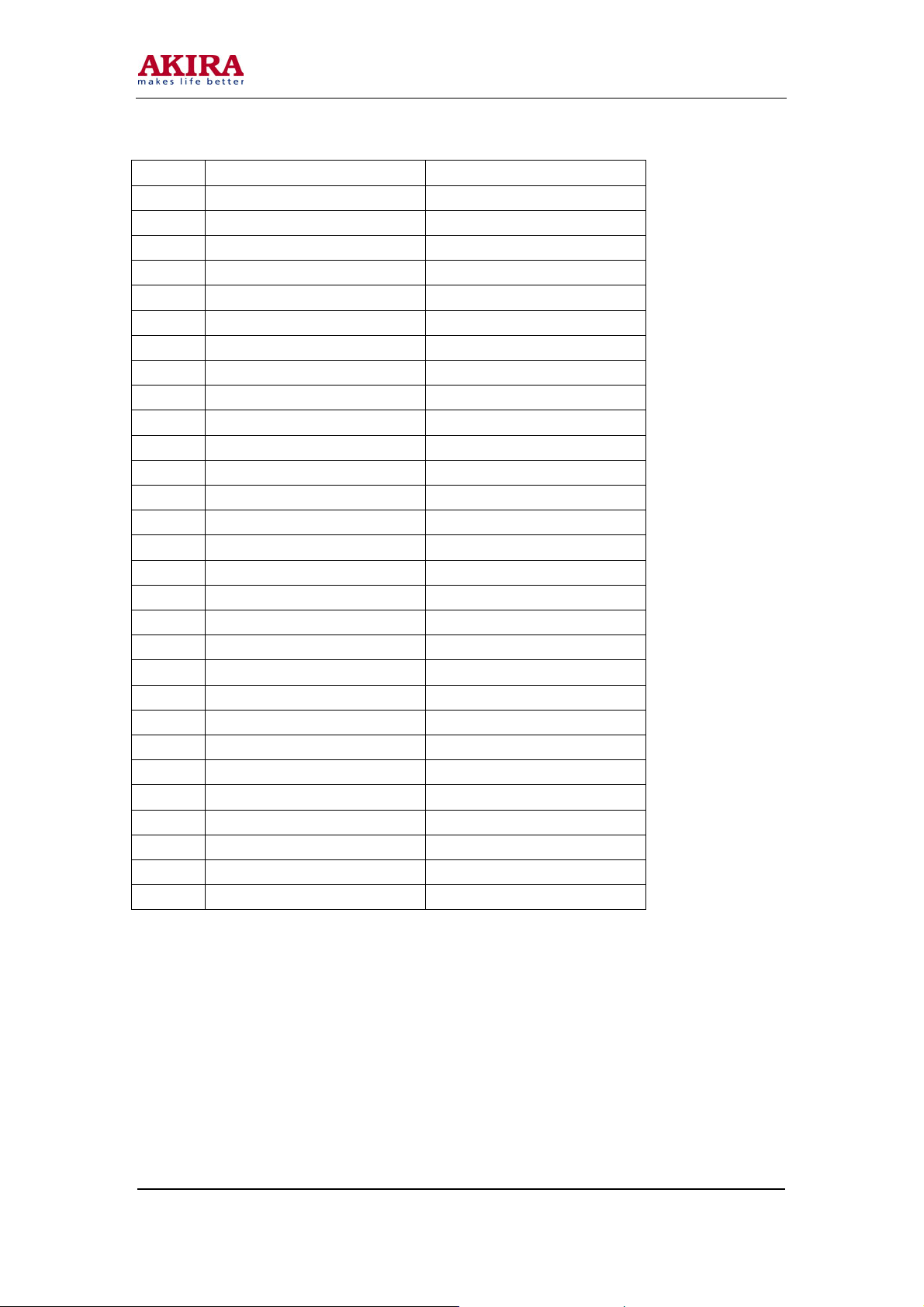
CN72M (interface connector)
Pin No. Symbol Description
1 VLCD +12Vcc
2 VLCD +12Vcc
3 RA0 Red Data (LSB)
4 RA1 Red Data
5 RA2 Red Data
6 RA3 Red Data
7 RA4 Red Data
8 RA5 Red Data
9 GND Ground
10 GND Ground
11 RA6 Red Data
+24V
GND
Model No.: LCT-20CVST
Version: 1.0
Page 13
-13 -
Pin No. Symbol Description
12 RA7 Red Data (MSB)
13 GA0 Green Data (LSB)
14 GA1 Green Data
15 GA2 Green Data
16 GA3 Green Data
17 GND Ground
18 GND Ground
19 GA4 Green Data
20 GA5 Green Data
21 GA6 Green Data
22 GA7 Green Data (MSB)
23 BA0 Blue Data (LSB)
24 BA1 Blue Data
25 GND Ground
26 GND Ground
27 BA2 Blue Data
28 BA3 Blue Data
29 BA4 Blue Data
30 BA5 Blue Data
31 BA6 Blue Data
32 BA7 Blue Data (MSB)
33 GND Ground
34 GND Ground
35 LVSYNC Vertical sync
36 LCKA Dot Clock
37 GND Ground
38 GND Ground
39 LHSYNC Horizontal Sync
40 LDTC Data Enable
Model No.: LCT-20CVST
Version: 1.0
Page 14
-14 -
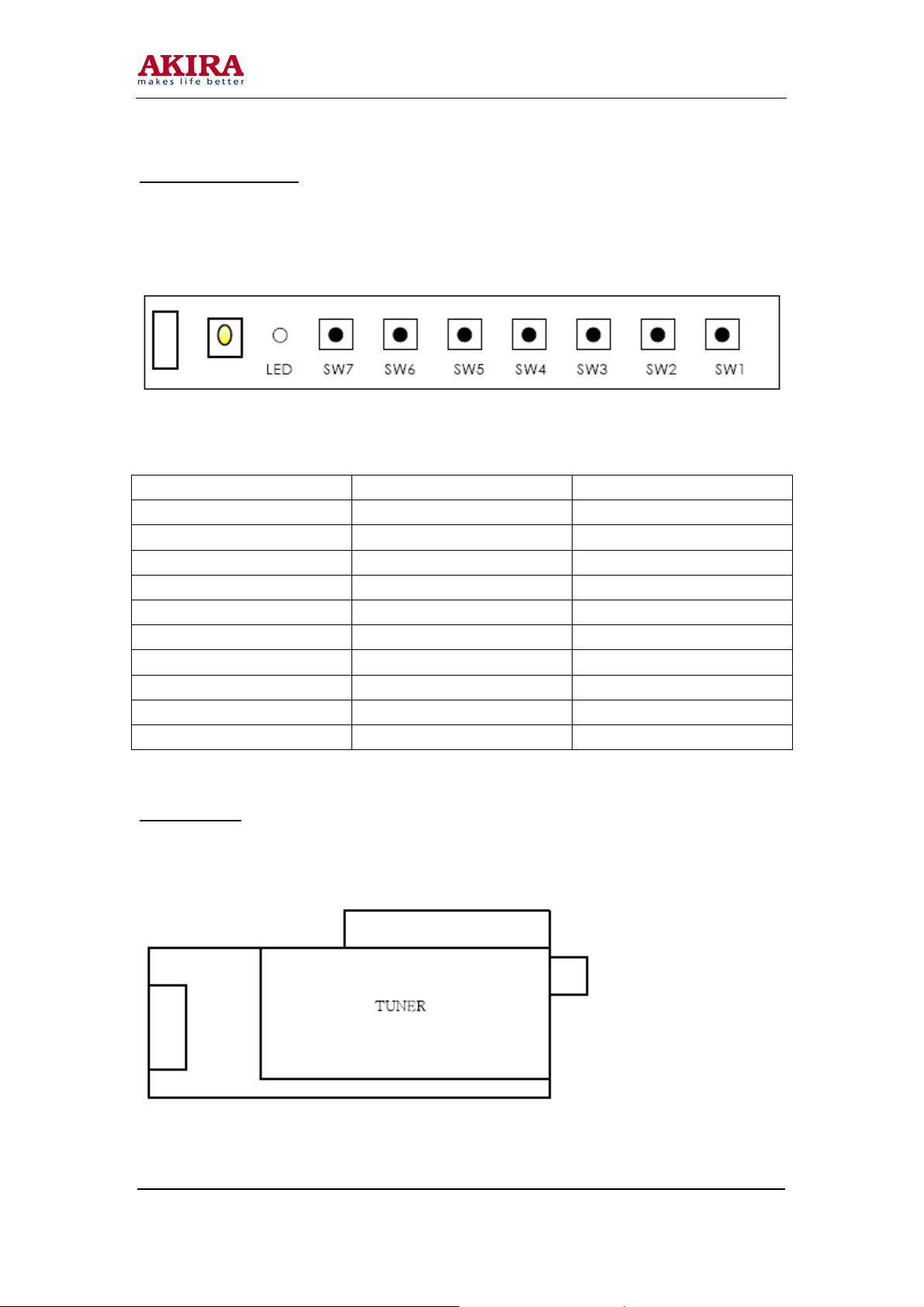
OSD Control Board
OSD Key Pad Control Board Assembly.
The Control Board assembly is the OSD user control /interface.
Control PCB connector and switch identification.
Reference Description Connector type
Sw1 POWER IT-1102AH-T
Sw2 SELECT IT-1102AH-T
Sw3 VOL+ IT-1102AH-T
Sw4 VOL- IT-1102AH-T
Sw5 CH+ IT-1102AH-T
Sw6 CH- IT-1102AH-T
Sw7 Menu IT-1102AH-T
LED LED SAM3270
RM03 Remocon reciver Rom-N338TM2
CNC01 OSD Connector MOLEX 53015-0810
Tuner board
Tuner control board assembly
Model No.: LCT-20CVST
Version: 1.0
Page 15

-15 -
Tuner specification
Model TCPQ9091PD27D(T) (SAM SUNG)
Receiving PAL – B /GD /K, I
SECAM L /L’
Channel
UHF 471.25MHz ~ 855.25MHz
TUNER PCB connector and switch identification
Pin No Symbol Description
1 VCC +5V
2 GND GND
3 SDA I2C serial Data
4 SCL I2C serial clock
5 GND GND
6 CVBS CVBS out
7 GND GND
8 SIF Sound if out
LOW 48.25MHz ~ 168.25MHz VHF
HI 175.25MHz ~ 463.25MHz
Model No.: LCT-20CVST
Version: 1.0
Page 16

BLOCK DIAGRAM
-16 -
Model No.: LCT-20CVST
Version: 1.0
Page 17

-17 -
IMPORTANT IC LIST
No Part type Specification Package Qty Ref No
1 IC image
scaller
2 IC Video VPC3230D-C5 PQFP-80 1 IC301
3 IC Audio MSP3410G-B8 PQFP-80 1 IC201
4 IC Video S/W TEA6425D SOIC 1 IC302
5 IC ADC MST9883C-110 LQFP-80 1 IC360
6 IC Memory HY57V16160DTC-7 SOP-50 2 IC701, IC702
7 IC Micom S3P863AXZZ /OTP
8 IC TTX SAA5264PS /M3
9 IC Audio
AMP
10 IC RGB S/W TEA5114A DIP DIP 1 ICS1
11 IC EEPROM 24C16 ROM DIP DIP 1 IC002
12 IC Logic N74F14D SOIC 1 IC362
13 IC EEPROM 24C02 DIP DIP 1 ICX2
14 IC Reset KIA7042AF SOT-89 1 IC003
Model No.: LCT-20CVST
Version: 1.0
MX88L284AEC QFP-282 1 IC601
DIP 1 IC0001
DIP
DIP 1 ICX1
/0104 DIP
TDA1519B SOT110 1 IC251
Page 18

-18 -
TROUBLE SHOOTING
What you see Suggestion actions Reference
Screen is blank and power
indicator is off
“CHECK CABLE OR SIGAL”
message
“INVALID MODE” massage Check the maximum resolution
The image is too light or too dark Adjust the brightness and
Horizontal bars appear to flicker,
jitter or shimmer on the image
Vertical bars appear to flicker,
jitter or shimmer on the image
Image is not stable and may
appear to vibrate
Model No.: LCT-20CVST
Version: 1.0
Ensure that the power cord is
firmly connected and the LCD
monitor is on
Ensure that the signal cable is
firmly connected to the PC or
video sources.
Ensure that the PC or video
sources are tuned on.
and the frequency of the video
adaptor.
Compare these values with the
data in the display modes timing
chart.
contrast.
Adjust the clock function. Auto
tracking will clear it
automatically.
Adjust the phase function and
then adjust the clock function.
Auto tracking will clear it
automatically.
Auto tracking will clear it
automatically.
Check that the display resolution
and frequency from your PC or
video board is an available mode
for your monitor.
On your computer check control
panel, display, setting.
Horizontal frequency
Vertical frequency
Maximum refresh rate
Connecting a PC.
Connecting a PC, TV, VCR.
PC stable adjustment.
PC stable adjustment.
31khz
56~85hz
640*480 @ 60hz
Page 19

-19 -
What you see Suggestion actions Reference
Image is not centered on the
screen
No sound Adjust the horizontal and
Sound level is too low Check the volume level
Sound is too high pitched or too
low pitched
TV signal is not received Ensure that the antenna cable is
Auto position will set the best
position automatically
vertical position.
Ensure that the audio cable is
firmly connected to both the
audio-in jack on your monitor
and the audio-out jack on your
sound card.
Check the volume level.
If the volume is still too low after
turning the control to its
maximum, check the volume
control on the computer sound
card or software program.
Adjust the treble and bass to
appropriate level.
firmly connected to the VHF
/UHF jack.
Check “channel memory” and
make sure you choose the
correct channel system.
Select “Auto tuning” to
configure the channel system
automatically.
Auto position, h position
v-position.
Connecting a PC, TV, VCR.
Refer to your computer,
sound card or software
documentation.
Channel memory.
Model No.: LCT-20CVST
Version: 1.0
Page 20

-20 -
, 2,
No power
Check & replacement panel
No power
Check output
level
YES
Check IC800 #4
DC5V level
YES
Check IC803 #4
DC12V level
YES
Check IC804 #4
DC5V level
YES
Check IC806 #4
DC3.3V level
YES
NO
NO
NO
NO
NO
Replacement power cord
Check CN70M
3 DC24V
#1
Check IC801 #5,
6, 7, 8 DC24V
Check & replacement
IC804
Check &
replacement IC806
NO
YES
NO
YES
Replacement power B/D
Replacement IC800
Check IC801
Replacement IC803
Model No.: LCT-20CVST
Version: 1.0
Page 21

-21 -
No LED & key control
No LED & key control
Check CN01M
pin spec check
YES
Check IC001 #2, 3,
7, 35 pulse check
YES
Check &
replacement OSD
key
NO
NO
OSD PCB short
check & OSD
cable check
IC800 #4 DC5V level check
Replacement U-com IC001
NO
Replacement
OSD PCB or
cable
Model No.: LCT-20CVST
Version: 1.0
Page 22

EXPLODED VIEW
-22 -
Model No.: LCT-20CVST
Version: 1.0
Page 23

-23 -
Model No.: LCT-20CVST
Version: 1.0
Page 24

-24 -
Model No.: LCT-20CVST
Version: 1.0
Page 25

-25 -
Model No.: LCT-20CVST
Version: 1.0
Page 26

-26 -
Model No.: LCT-20CVST
Version: 1.0
Page 27

-27 -
Model No.: LCT-20CVST
Version: 1.0
Page 28

-28 -
Model No.: LCT-20CVST
Version: 1.0
Page 29

-29 -
Model No.: LCT-20CVST
Version: 1.0
Page 30

-30 -
PART LIST
No Part name Qty
1-1 Front cover 1
1-2 Key knob 1
1-3 OSD PCB 1
1-4 Window 1
1-5 BTS-(TT) 3*8 2
1-6 OSD PCB cable 1
2-1 LCD-Panel 1
2-2 Main chassis 1
2-3 BHS M3x5 4
2-4 TTB (TT) 3x8 6
3-1 Main PCB 1
3-2 Speaker ass’y 1
3-3 PTS (TT) 4x8 8
3-4 BMS 4x6 4
4-1 Power-lips 1
4-2 Signal-cable 1
4-3 BMS 4x6 4
5-1 EMI-cover 1
5-2 Tuner-PCB 1
5-3 Tuner cable 4
5-4 Lips cable 1
5-5 BMS M3x6 2
5-6 BTS (TT) 3x6 10
6-1 Rear cover 1
6-2 PTS (TT) 4x10 8
6-3 Tuner cover 4
6-4 WPTS (TT) 4x8 1
7-1 Base cover 1
7-2 Metal base 1
7-3 BTS (TT) 3x8 6
7-4 Hinge body 1
7-5 Base cover-F 1
Model No.: LCT-20CVST
Version: 1.0
Page 31

-31 -
No Part name Qty
7-6 BHM M3x6 2
7-7 BHM M4x10-SEMS 4
7-8 Base cover-R 1
7-9 BHM M3x6 1
8-1 Stand ass’y 1
8-2 PMS M4x12-SEMS 4
8-3 Hinge cover 1
Model No.: LCT-20CVST
Version: 1.0
Page 32

CIRCUIT DIAGRAM
BLOCK DIAGRAM (PAL)
-32 -
Model No.: LCT-20CVST
Version: 1.0
Page 33

BLOCK DIAGRAM (NTSC)
-33 -
Model No.: LCT-20CVST
Version: 1.0
Page 34

POWER
-34 -
Model No.: LCT-20CVST
Version: 1.0
Page 35

U-COM
-35 -
Model No.: LCT-20CVST
Version: 1.0
Page 36

AD9883
-36 -
Model No.: LCT-20CVST
Version: 1.0
Page 37

VPC3230
-37 -
Model No.: LCT-20CVST
Version: 1.0
Page 38

SCALER
-38 -
Model No.: LCT-20CVST
Version: 1.0
Page 39

MEMORY
-39 -
Model No.: LCT-20CVST
Version: 1.0
Page 40

SOUND IC
-40 -
Model No.: LCT-20CVST
Version: 1.0
Page 41

SOUND AMP
-41 -
Model No.: LCT-20CVST
Version: 1.0
Page 42

TTX /CAPTION
-42 -
Model No.: LCT-20CVST
Version: 1.0
Page 43

LVDS
-43 -
Model No.: LCT-20CVST
Version: 1.0
Page 44

KEY CONTROL
-44 -
Model No.: LCT-20CVST
Version: 1.0
Page 45

TUNER
-45 -
Model No.: LCT-20CVST
Version: 1.0
Page 46

 Loading...