

Page 1

LCD TV
Service Manual
Page 2

-2 -
MODEL:
LCT-15CH12ST
CHASSIS
INFO: LS-07
Model No.: LCT15CH12ST. doc
Version: 1.0
Page 3

-3 -
CONTENTS
SAFETY PRECAUTION.........................................................................................................................4
MAIN FEATURE.....................................................................................................................................6
ELECTRIC CIRCUIT..............................................................................................................................9
MAIN ICs FUNCTION..........................................................................................................................10
SYMPTOMS & CORRECTION............................................................................................................24
LIST OF BREAKABLE & MAINTENANCE PARTS..........................................................................25
FACTORY MODE.................................................................................................................................27
EXPLODED VIEW................................................................................................................................28
PART LIST ...........................................................................................................................................29
WIRING DIAGRAM.............................................................................................................................30
CIRCUIT DIAGRAM............................................................................................................................31
WALL-MOUNTING BRACKET INSTALLATION GUIDE................................................................38
Model No.: LCT15CH12ST. doc
Version: 1.0
Page 4
-4 -
1.
IMPORTANT SAFETY PRECAUTION
Model No.: LCT15CH12ST. doc
Version: 1.0
Page 5
-5 -
Model No.: LCT15CH12ST. doc
Version: 1.0
Page 6

-6 -
MAIN FEATURE
RF input ,CATV function
Capable to receive the full append cable programs in 470MHZ, can
store 100 programs (Program number display 0~99);
AV Audio and AV Video input
In SCART mode, the system can automatically activate SCART
checking function to identify signal input modes(CVBS or RGB) and
input signal character(16:9 or 4:3); Capable to receive PAL, NTSC,
SECAM color systems; Very convenient to watch VCR (video
cassette recorder), Pickup Camera and other Disc’s programs.
YPbPr input
Can receive high definition YPbPr component video signal from
such as DVD Conveniently . Support format:480I、480P、576I、576P、
720P(50/60HZ)、1080I(50/60HZ)、1080P(50/60HZ);
VGA input
As the Terminal display Equipments of computer, it can connect with
computer conveniently. it can connect with Computer audio card by
its own Audio connection line ,so you can listen the audio
information from computer.
Program lock and child lock function
The function of program lock can lock the programs、input password
and Modification, the function of child lock can lock the keys.
Timer function
You can set turn on and turn off on time, and power off in 15 min
automatically if no signal input. Automatically enter into save energy
mode by itself if no signal in PC condition, it can be awaken if signal
inputs.
Blue screen mute noise
In condition of TV、AV、RGB and YPbPr, gentle blue screen will be
Model No.: LCT15CH12ST. doc
Version: 1.0
Page 7

-7 -
displayed if no signal input.
Chinese/English menu
Adopt the design of Convenient and Simple graphic menu, you can
operate menu more conveniently and more intuition.
Save energy function(power management mode)
When TV is used as PC display terminal, and PC has no output
signal . The TV will be power off in about 30 Seconds automatically,
and enter into standby condition. press down Power/P+/P-/ Number
key of Remote control or the PC signal appearance again, the TV
will be on automatically.
Plug-and-play
The TV works as the terminal Equipments of computer, need not
equip install software,it is real Plug-and-Play.
Automatic correct
By its automatic correct function ,the LCD TV can bring you the best
view.
No Flicker、no Radiation 、Green environmental protection
Because of it’s Advanced power Management mode, the TV can
realize standby and recall on function.
ACI function ( Auto channel Installation ).
Stereo and digital accompanying sound processing.
Auto identify and demodulate IGR, and decode NICAM digital
accompanying sound.
Zoom image function
Support follow zoom function: Full screen mode、4:3 mode(16:9
TFT),16:9(4:3 TFT)、Movie mode、Sub-title movie mode.
Light weight、small dimension、Low power consumption
Advanced picture quality Strengthen function
Dynamic skin color Correct: Improve distort color in picture, make it
Model No.: LCT15CH12ST. doc
Version: 1.0
Page 8

-8 -
Near to real color.
Black level Extension: blacken the more black area of picture, Raise
the contrast in Dark Background.
Color Edge correct: Increase the Steep of color signal edge ,make
the edge of color Transition more clearly .
Brightness edge correct: increase the steep of Brightness signal
edge, make the edge of picture is more clearly.
Super fine and inner fairness TFT
10-page teletext storage
Dynamic comb filter
Headphones output
Model No.: LCT15CH12ST. doc
Version: 1.0
Page 9
-9 -
ELECTRIC CIRCUIT
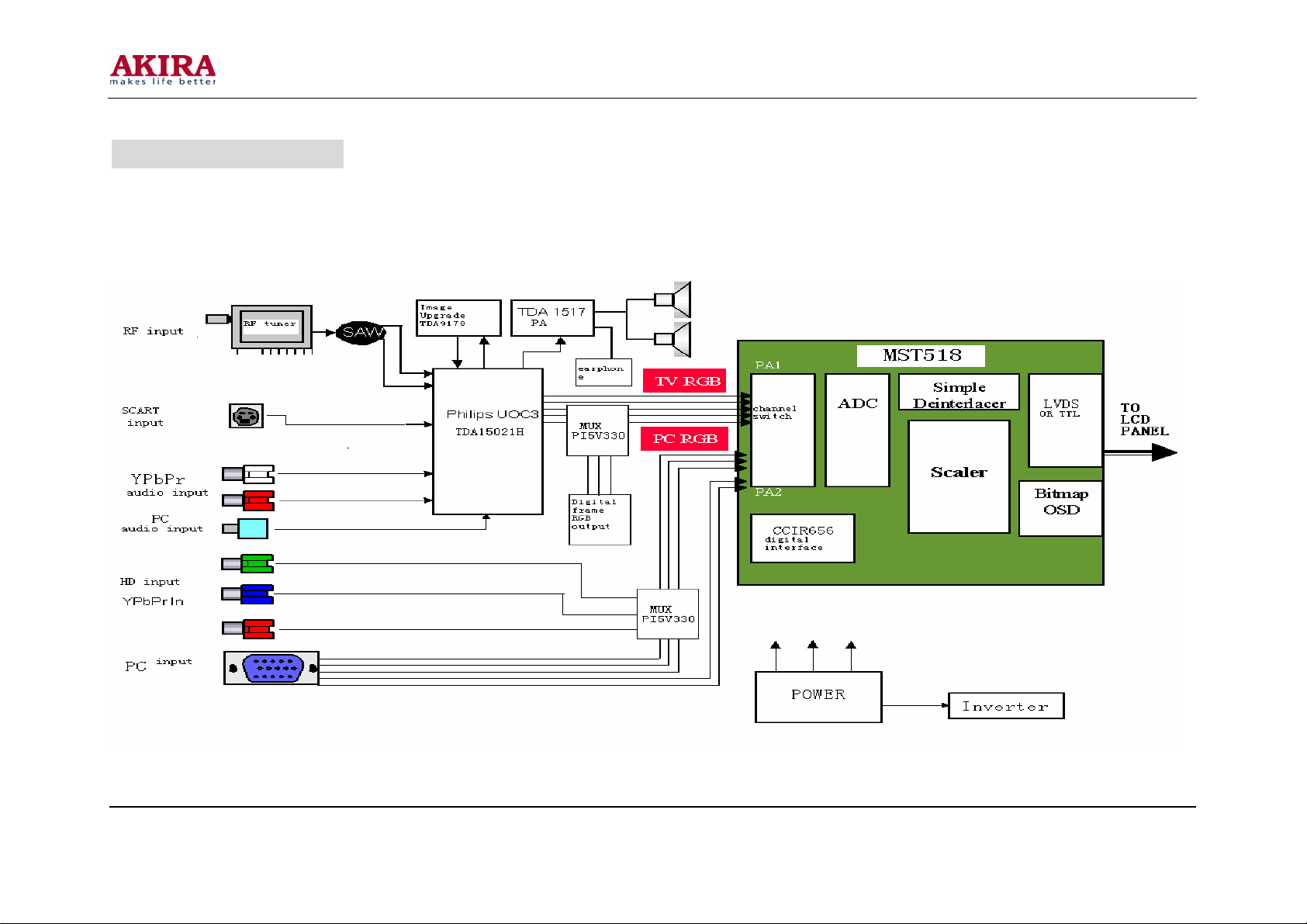
The LS07 chassis LCD TV is composed of steady voltage circuit、inverter Circuit 、RF circuit、video Strengthen circuit、video
Processing circuit、Power Enlarge circuit、VGA circuit、system control circuit and key control circuit. The block diagram of circuit
Constitute as below:
Model No.: LCT15CH12ST. doc
Version: 1.0
Page 10
-10 -
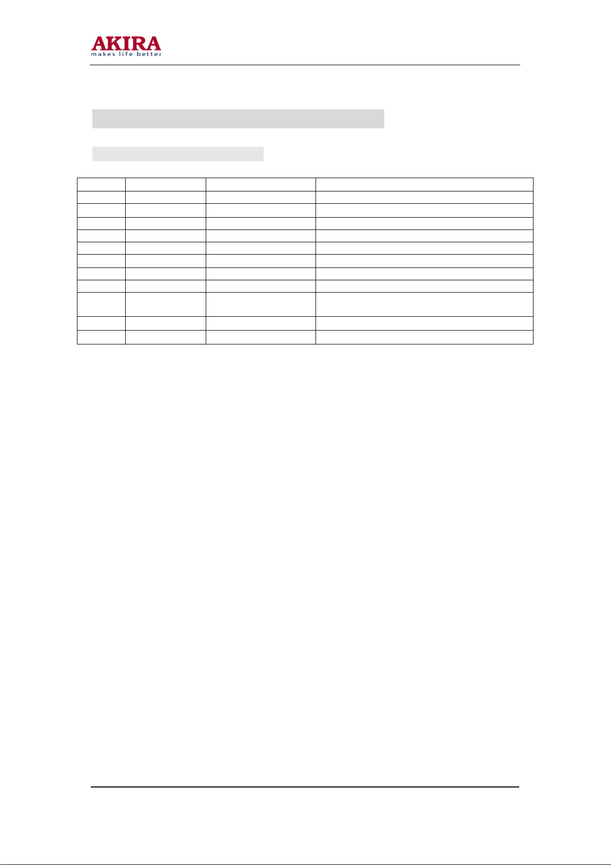
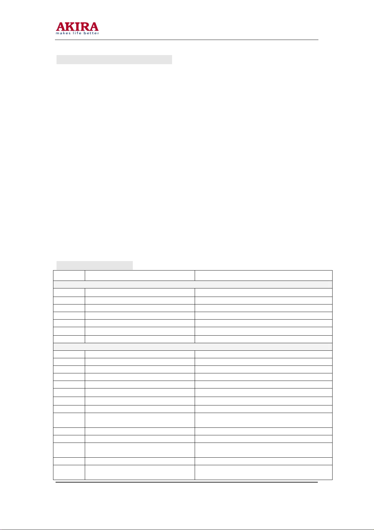
MAIN ICs FUNCTION INTRODUCTION
GENERAL INTRODUCTION
No. Name Model Main Function
1 A1 TAF5-E2I21RW2 RF tuner
2
3 U3 MST518 AD converter and format change
4 U2 UOC(TDA15021H) Video decode and MCU control
5 Q9 Si2311DS MOS switch
6
7 U19 NTMS10P02 MOS switch
8 U23 LM2596-5.0 Liner voltage IC
9 U1 24LC21A
10 U4 24LC32A
11
U8、U21
U11、U12
U6、U20
TDA1517AWT Audio amplifier
IRF7316 MOS switch
EEPROM(save display parameter
information)
EEPROM(save user control information)
PI5V330A Video switch
Model No.: LCT15CH12ST. doc
Version: 1.0
Page 11
-11 -
1. MST518 High Integration Chip:
MST518 is a high performance、high integration image processor which is
designed for LCD, it can support SXGA format (1280*1024).it integrates a
group of AD converter 、high quality format transform system、OSD generator、
output clock generator、multiple format output display interface (support TTL、
LVDS、RSDS)
MST518 feature:
z Have high quality Expand transform and compress transform, can
output XGA format signal
z Integrated LVDS circuit inside
z 8 bit high quality ADC inside
z Double VGA input, Software switch
z Support ITU-656 format signal input
z Support H/V sync、composite sync、green composite sync input, and
detect automatically by itself
z Programmable 10 bit Gamma correct, the brightness and contrast is
adjustable
z 8 color、256 Character OSD
z Built-in DDC circuit inside
z Low standby power
Support TTL、double LVDS signal output, Software switch
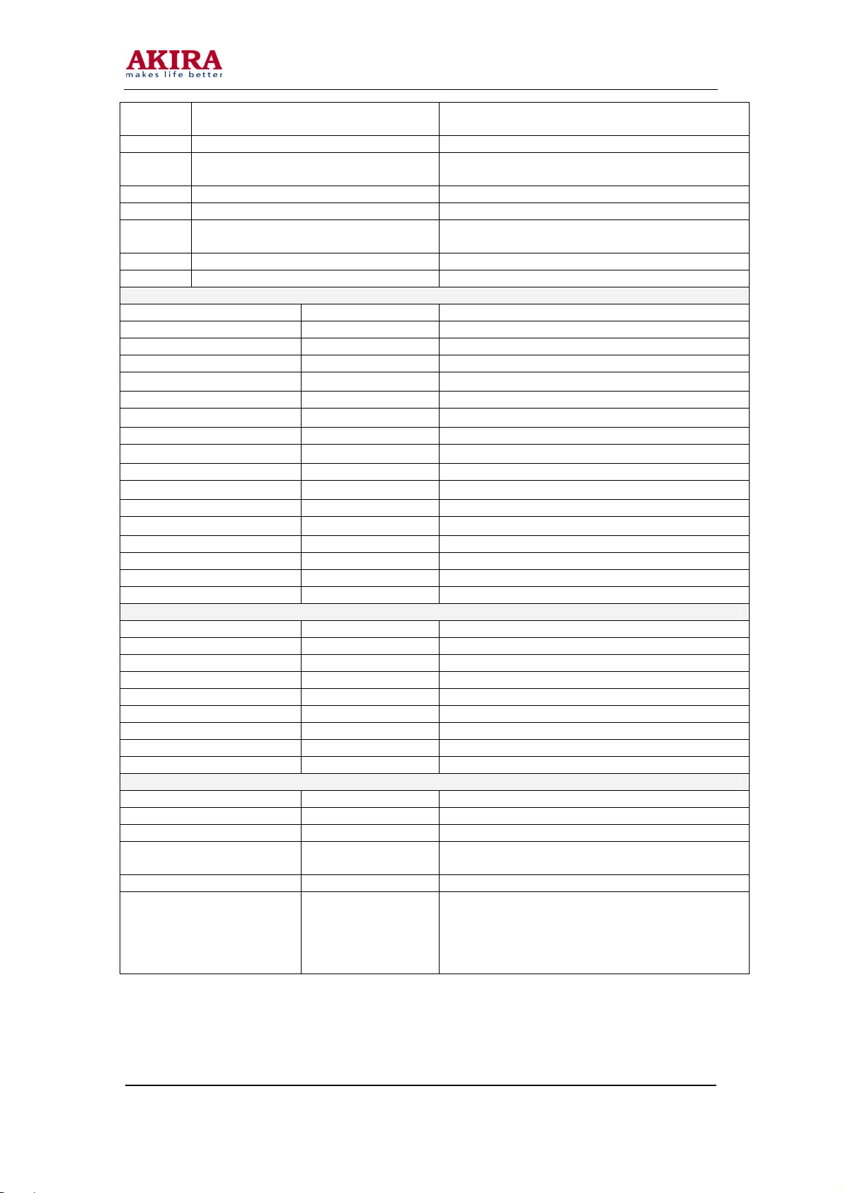
MST518 Pin Function:
Pin Definition Pin Function
CPU Interface
33 HWRESET
82 Chip select signal of three-wire serial bus
83 data signal of three-wire serial bus
84 SCL clock signal of three-wire serial bus
85 INT interrupt
98-91 AD [7:0]
125 BUSTYPE Bus type select
Analog Interface
38 HSYNC0 Analog Horizontal sync signal input channel 0
39 VSYNC0 Analog vertical sync signal input channel 0
40 HSYNC1 Analog Horizontal sync signal input channel 1
41 VSYNC1 Analog vertical sync signal input channel 1
78 RMID Scalar internal reference. voltage
79 REFP
80 REFM
75 RIN0 Analog red signal input channel 0
74 RIN0M
73 SOGIN0 Green sync signal input channel 0
72 GIN0 Analog green signal input channel 0
71 GIN0M
70 BIN0 Analog blue signal input channel 0
69 BIN0M
Model No.: LCT15CH12ST. doc
Version: 1.0
Hardware reset,high voltage enable
Parallel bus,the chassis is not used
internal ADC decouple +
internal ADC decouple -
Analog red signal input channel 0 re-grounding
voltage
Analog green signal input channel 0
re-grounding voltage
Analog blue signal input channel 0
re-grounding voltage
Page 12
-12 -
66 RIN1M
65 RIN1 Analog red signal input channel 1
64 GIN1M
63 GIN1 Analog green signal input channel 1
62 SOGIN1 Green sync signal input channel 1
61 BIN1M
60 BIN1 Analog blue signal input channel 1
55 REXT Outside connect 390 with 3.3V
LCD Interface
145 OCLK Clock output
146 LDE enable signal
144 LVSYNC vertical sync output
143 LHSYNC Horizontal sync output
138 LVA0M
137 LVA0P LVDS output 0+
136 LVA1M
135 LVA1P LVDS output 1+
134 LVA2M
133 LVA2P LVDS output 2+
128 LVA3M
127 LVA3P LVDS output 3+
132 LVACKM
131 LVACKP LVDS clock signal output +
26-23,18-15 RB[7:0] TTL red signal channel
14-11, 8-5 GB[7:0] TTL green signal channel
4,3,154,153,150-147 BB[7:0] TTL blue signal channel
GPIO Interface
87 GOUT1/PWM1 PWM output 1
86 GOUT0/PWM0 PWM output 0
2 BYPASS Outside connect filter capacitor
29 DDC_DAT Analog interface DDC data
30 DDC_CLK Analog interface DDC clock
31 DDCROM_CLK DDC ROM clock
32 DDCROM_DAT DDC ROM data
34 XIN Crystal oscillator signal input
35 XOUT Crystal oscillator signal output
Power Pins
48, 54, 58, 77 AVDD A/D convert power supply
56 AVDD_PLL PLL power supply
36 AVDD_MPLL MPLL power supply
10, 22, 88, 99, 111,
129, 139, 151
19, 102, 114, 142 VDDC Digital circuit power supply
1, 9, 20, 21, 37, 42,
45, 51, 57, 59, 76,
81, 89, 100, 101,
112, 113, 130, 140,
141, 152
VDDP Digital signal output power supply
GND Digital circuit ground
Analog red signal input channel 1 re-grounding
voltage
Analog green signal input channel 1
re-grounding voltage
Analog blue signal input channel 1
re-grounding voltage
LVDS output 0-
LVDS output 1-
LVDS output 2-
LVDS output 3-
LVDS clock signal output-
Model No.: LCT15CH12ST. doc
Version: 1.0
Page 13

-13 -
MST518 Internal Diagram:
Model No.: LCT15CH12ST. doc
Version: 1.0
Page 14

-14 -
2. TDA15021H:
The third-generator super integrated circuit UOC III which designed by Philips company
recently integrates with video decode、2D comb filter、high quality audio transacting technique,
suitable with the European teletext technique and suitable with US closed caption and V-chip
function compatible with single series IC. The series of UOC III have high integrity, besides
completing the Processing of all small signal (IF signal demodulation, video decode, H/V
signal, sound DSP), and integrate all the MCU function. It has many Advantages, example: the
compact circuit、good performance、simple craft, etc. it matches with company’s high
performance price ratio and high product efficiency demanding. It is suitable for 4:3 or 16:9、
50/60HZ and A100/120HZ TV system, the main characteristic below:
z Multi-system IF demodulation、analog video decode
z Comb filter internal
z NICAM、stereo auto identify and decode
z SCART input channel source auto identify(RGB、CVBS),SCART image input format
identify(4:3、16:9)
z Support 4:3、16:9 display format
z TOP/FLOF TELETEXT(10 page)receive display
z Channel auto install ACI function(can preset)
z 4 CVBS or 3 Y/C input,1 CVBS output,2 YcrCb/2 RGB input
z 4 AV audio input,1 AV adjustable audio volume output
z Volume auto level control circuit
z Global FM demodulation
z Picture quality enhancement of dynamic peak value control、skin color correct、Gamma
correct、Black level extension etc.
z Can turn down horizon and vertical scan part,output H/V sync. signal to Scalar
z 128K Flash Memory inside, support program on line
z Automatic Y/C signal identify
TDA15021H Pin Function:
Pin Definition Pin Function
1 VSSP2 Grounding
2 VSSC4 Grounding
3 VDDC4 +1.8V
4 VDDA3 +3.3V
5 VREF_POS_LSL +3.3V
6 VREF_NEG_LSL+HPL 0V
7 VREF_POS_LSR+HPR +3.3V
8 VREF_NEG_HPL+HPR 0V
9 VREF_POS_HPR +3.3V
10 XTALIN Crystal oscillator input
11 XTALOUT Crystal oscillator output
12 VSSA1 Grounding
13 VGUARD/SWIO Protecting voltage input or I/O
14 DECDIG DECDIG signal input
15 VP1 +5V
16 PH2LF The second grade horizontal phase lock filter
17 PH1LF The first grade horizontal phase lock filter
18 GND1 Grounding
19 SECPLL SECAM PLL decouple
20 DECBG Inside reference voltage decouple
21 EWD/AVL VDD5A voltage input
22 VDRB TV vertical sync signal output
Model No.: LCT15CH12ST. doc
Version: 1.0
Page 15

-15 -
23 VDRA vertical sync output
24 VIFIN1 VIF input 1
25 VIFIN2 VIF input 2
26 VSC Outside connect vertical ramp capacity
27 IREF Re-current input
28 GNDIF IF grounding
29 SIFIN1 SIF input 1
30 SIFIN2 SIF input 2
31 AGCOUT tuner RF AGC control voltage output
32 EHTO Over voltage protection input
33 SSIF MUTE control signal input
34 AUDIOIN5L Av left track signal input
35 AUDIOIN5R Av right track signal input
36 AUDOUTSL SCART/CINCH left track output
37 AUDOUTSR SCART/CINCH right track output
38 DECSDEM Track demodulator decouple
39 QSSO De-emphasis capacitor
40 GND2 grounding
41 PLLIF IF_PLL filter
42 SIFAGC Sound intermediate frequency auto gain control
43 IFVO IF demodulation video output
44 FMRO Fm broadcast output
45 VCC8V The supply voltage of Sound switch
46 AGC2SIF
47 VP2 +5V
48 IFVO The video output of Choose channel
49 AUDIOIN4L HD signal left track audio output
50 AUDIOIN4R HD signal right track audio output
51 CVBS4/Y4 S-video luminance signal input
52 C4 S-video chroma signal input
53 AUDIOIN2L PC signal left track audio input
54 AUDIOIN2R PC signal right track audio input
55 CVBS2/Y2 AV CVBS signal input
56 AUDIOIN3L Inside DVD module left track audio input
57 AUDIOIN3R Inside DVD module right track audio input
58 CVBS3/Y3 Inside DVD module brightness signal input
59 C2/C3 Inside DVD module chroma signal input
60 AUDOUTLSL Main channel left track output
61 AUDOUTLSR Main channel right track output
62 AUDOUTHPL Earphone channel left track output
63 AUDOUTHPR Earphone channel right track output
64 CVBS/PIP CVBS/PIP output
65 SVM Scan modulate output
66 FBISO
67 HOUT Horizontal sync signal output
68 VSS comb Grounding
69 VDD comb +5V
70 VIN V signal input
71 UIN U signal input
72 YIN Y signal input
73 YSYNC Y signal input for Sync separate
74 YOUT Y signal output
75 UOUT U signal output
76 VOUT V signal output
77 INSSW3 RGB / YpbPr insert identify signal input
The second sound intermediate frequency auto
gain control
Fly back input/sandcastle output or composite H/V
timing output
Model No.: LCT15CH12ST. doc
Version: 1.0
Page 16

-16 -
78 R/PrIN3 R/Pr signal input
79 G/YIN3 G/Y signal input
80 B/PbIN3 B / Pb signal input
81 GND3 Grounding
82 VP3 +5V
83 BCLIN Beam current limiter input
84 BLKIN Black current input
85 RO R basic color signal input
86 GO G basic color signal output
87 BO B basic color signal output
88 VDD3 +3.3V
89 VREFAD_NEG 0V
90 VREFAD_POS +3.3V
91 VREFAD Audio ADC re voltage
92 GNDA Grounding
93 VDDA +1.8V
94 VDD3A +3.3V
95 VSSADC Grounding
96 VADC +1.8V
97 INT0 Remote control signal input
98 P10/INT1 DPF clock line
99 P11/T0 DPF data line
100 VDDC2 +1.8V
101 VSSC2 Grounding
102 P04/12SWS MST reset signal
103 P03/12SCLK HD,PC select control signal
104 P02/12SDO2 Power Amplifier standby control signal
105 P01/12SDO1 TV-DPF select control signal
106 P00/12SDII/O Turn on control signal
107 P13/T1 MST chip select signal
108 P16/SCL UOCI2C bus clock line
109 P17/SDA UOCI2C bus data line
110 VDDP +3.3V
111 P20/TPWM Red indicator light control signal
112 P21/PWM0 Green indicator light control signal
113 P22/PWM1 TFT power supply control signal
114 P23/PWM2 Inside DVD module power supply control signal
115 P30/ADC0 Reserve IO port
116 P31/ADC1 Earphone insert identify signal input
117 VDDC1 +1.8V
118 VDD18 +1.8V
119 P32/ADC2 DVD key-press signal input
120 P33/ADC3 TV key-press signal input
121 VSSC Grounding
122 P24/PWM3 Background control signal output
123 P25/PWM4 SAW filter control signal
124 VDDC3 +1.8V
125 VSSC3 Grounding
126 P12/INT2 MST interrupt signal input
127 P14/RX MST data line
128 P15/TX MST clock line
Model No.: LCT15CH12ST. doc
Version: 1.0
Page 17

-17 -
TDA15021H Internal Block Diagram:
Model No.: LCT15CH12ST. doc
Version: 1.0
Page 18

-18 -
3 TDA9178 :
TDA9178 is an analog signal processor with standard YUV input and output interface .It
provide three main process functions: luminance vector, color vector and spectrum
process. It can finish comprehensive picture improving function independently. The
characteristics of the TDA9178 are below:
z Luminance Transient Improvement (LTI), Colour Transient Improvement (CTI)
z Variable gamma control
z Self-suitable black level extend control
z Skin color correction, green intensity ,blue extend
z Noise measurement and reduced noise process function
z Line Width Control (LWC)
TDA9178 PIN FUNCTION
Pin Definition Pin Function
1 Sandcastle input Sandcastle input
2 Not connected Grounding
3 ADC input 1 A/D converter input 1
4 ADC input 2 A/D converter input 2
5 ADC input 3 A/D converter input 3
6 Luminance input Y input
7 Address selection input I2C address choose input port
8 U signal input U input
9 V signal input V input
10 Test pin Grounding
11 Serial clock input (I2C-bus) I2C bus clock signal
12 Not connected Not connected
13 Not connected Not connected
14
15 Decoupling digital supply Connect decouple capacitor external
16 V signal output V signal output
17 U signal output U signal output
18 Ground Ground
19 Luminance output Y signal input
20 Supply voltage Supply power
21 SCAVEM output Scan velocity modulate output
23 Not connected Grounding
24 Not connected Grounding
Model No.: LCT15CH12ST. doc
Version: 1.0
Serial data input/output
(I2C-bus)
I2C bus data signal
Page 19

-19 -
DA9178 Internal Block Diagram:
Model No.: LCT15CH12ST. doc
Version: 1.0
Page 20

-20 -
4 TDA1517AWT :
The TDA1517ATW is a double channel class-AB power amplifier contained in a plastic
heat sink thin shrink small outline package (HTSSOP20). The device is primarily
developed for multimedia applications.
a) Outside circuit is simple
b) Mute、standby is controllable
c) Temperature protect circuit
d) low noise switch
e) Constant gain
TDA1517 PIN FUNCTION:
Pin Definition Pin Function
3 Non-inverting input Audio input
5 Supply voltage ripple rejection Bias circuit filter
8、9
12、13
15、16
17 Mode select switch Work mode select
18 Inverting input
1、2、4、6、
7、10、11、
14、19、20
TDA1517 Inner Block Diagram:
Output Audio output
N.C. Not connected
Supply voltage
GND ground
+12V power supply
Reverse input terminal (connect capacitor to
ground )
Model No.: LCT15CH12ST. doc
Version: 1.0
Page 21

-21 -
SINGNAL PROCESSING FLOWCHART
I. Analog Signals Process
1 IF/RF process
Completed by TAF5-E2I21RW2 RF tuner, output IF signal.
The Function of RF tuner as below:
Pin Symbol Function
1 AGC Auto gain control voltage
2 TU The TV do not connect
3 ADD Ground
4 SCL
5 SDA
6 BM +5V power supply
7 BM +5V power supply
8 NC Not connected
9 BTL
10 NC Not connected
11 IF IF signal output
II. Image and Sound Process
UOC chip receives the IF signal separated from SAW, detect and decode. Output RGB
color analog signals from the 85、86、87 pin respectively. Output the main channel L、R audio
signal from 60、61 pin. Output earphone channel L、R audio signal from 62、63 pin. additional,
Part number U7,TDA9178 complete the enhancement of quality of the picture ,by the output
74、75、76 pin Of UOC and the input 70、71、72 pin, combined with UOC to form a loop circuit.
Further, AV、S-Video、YC signal of inside DVD(some types of TV have not) is also decoded
inside of UOC chip, switch internal UOC with TV input and output a RGB color analog signal,
send it to back-end process.
III. Digital Signal Processes
The analog RGB signal output from UOC and RGB signal output from DFP are switched
and selected by a PI5V330A; input it into the 65、63、60 pin Of MST518. The RGB signal output
from computer and HD-YpbPr signal are switched and selected by another PI5V330A,input
into the 75、72、70?of MST518.This two channel RGB signal are switched inside
MST518,then AD converter, video format transition, at last output digital color signal which is
suitable for TFT drive circuit. MST518 process the pixels ratio converting of input video signal、
the image auto optimization process, then process memory buffer、scaler、chroma matrix
circuit、chroma look-up table、chroma space gain, etc. Output corresponding standard physical
resolution digital color signal and corresponding sync, clock signal to TFT, control the TFT to
display image correctly.
2
C bus(clock )
I
2
C bus(data )
I
+32V power supply,form 0~32V tune voltage
Model No.: LCT15CH12ST. doc
Version: 1.0
Page 22

-22 -
5 TV Power Supply System:
(1) The supply power system of the main IC as below:
z 12V:the unit main power supply
z +34V:RF tuner tune voltage
z VCC5: stable and constant +5V power supply
z VCC5A: +5V power supply software can turn off
z V3_3D:UOC digital part supply power supply
z V1_8V1:UOC digital part constant supply power supply
z V1_8V2:UOC digital part power supply can be turned off
z V2_5M:MST518 digital core supply power supply
z V3_3M:MST518 supply power supply
(2) The constitute and distributing of the TV
12V
U8
LM2596-
U18
PWRON
5.0
7805
Double
voltag e
L3
VCC5
C188
+32V
VCC5A
VCC5
PWRON
IRF7316
U13
NCP1117
12Va
VCC5_SW
U11
V3_3D
V3_3M
VCC5
12V
U17
7808
U14
LM1084_3
.3V
U15
LM1117_2
.5V
U22
NPC1117D
FB39
FB40
FB41
V3_3M
V2.5M
TO INVERTER
TO TDA9178
Fi l ter
Fi l ter
Fi l ter
Filter
Filter
Q9
NTMS10
P02R
U19
NTMS10
P02R
VPO
VAD
VPLL
VDPLL
VDD
V1_8V1
V1_8V2
VLCD
12V
U23
LM2596-
5.0
L6
TO DPF OR DVD
C294
Model No.: LCT15CH12ST. doc
Version: 1.0
Page 23

-23 -
KEY PART AND FUNCTION
No. Name Element Function Description
A A1 RF tuner TAF5-E2I21RW2 RF input, IF output
B U2 UOC(TDA15021H) Video decode and MCU control
C U3 MST518 AD converter and format transition
D U20 PI5V330A Video switch on/off
E U6 PI5V330A Video switch on/off
F U11 IRF7316 MOS switch
G U9 LM2596-5.0 Linear voltage IC
H U23 LM2596-5.0 Linear voltage IC
I U19 NTMS10P02 MOS switch
J U21 TDA1517AWT Audio power amplifier
K U8 TDA1517AWT Audio power amplifier
L U4 24LC32A EEPROM(store user control information)
M Q9 Si2311DS MOS switch
N U12 IRF7316 MOS switch
O U1 24LC21A EEPROM(store display parameter information)
SOCKET AND DEFINITION
ITEM NAME FUNCTION
1 PWM PWM Dimming
2 APWM Analog PWM dimming
3 ON/OFF
4 GND
5 RX0- LVDS signal
6 RX0+ LVDS signal
7 GND
8 RX1- LVDS signal
9 RX1+ LVDS signal
10 GND
11 RX2- LVDS signal
12 RX2+ LVDS signal
13 GND
14 RCLK- LVDS clock signal
15 RCLK+ LVDS clock signal
16 GND
17 RX3- LVDS signal
18 RX3+ LVDS signal
19 GND
20 N.C.
21 N.C.
22 N.C.
23 GND
24 GND
25 GND
26 Panel power Module power
27 Panel power Module power
28 Panel power Module power
29 Panel power Module power
30 Inverter power Inverter logic power
Model No.: LCT15CH12ST. doc
Version: 1.0
Backlight On Off: 2.4-5.0V On
0-1V Off
Page 24

-24 -
SYMPTOMS AND CORRECTION
Symptom Reason and resolve
The display board of
PC no image in DVI.
No picture but sound,
on LOGO when
turning on the TV,
poor light is bright.
No picture, no sound,
no snowflake in TV
condition, but AV is
normal.
LCD TV can not be
controlled (inc red
lamp is no but the TV
is off, remote control
and key press in TV
can not control the
TV, etc.)
If some display board of DVI can not receive the data
when turning on the TV, there is no output; if pull out
the DVI line abruptly, there is also no DVI output;
Before starting PC, connect the DVI line with LCD TV
steadily. So DVI can receive the correct date from
DDC (Display Data Channel) when turning on the TV,
DDC is in chassis 24LC21.
Check the connect line in up screen, and connect the
line.
Check the outside of RF (also bus and power
supply), there is no problem but no output from RF,
so the RF is disabled.
The LCD TV can not work abruptly, power off and
turning it on again.
Model No.: LCT15CH12ST. doc
Version: 1.0
Page 25

-25 -
LISTS OF BREAKABLE AND MAINTENANCE PARTS
This list is provided for reference, if change the parameters of those maintain parts of an
apparatus, we do not notice in the future. The newest data regard as the correct type or
specification.
TM150F7E
Material Name Type(Module NO.)
Main board groupware JUJ6.690.033-2 8669000332J
Remote control panel
groupware
Key-press panel
groupware
Earphone panel
groupware
TFT LTM150XH-L06 68219601565
INVERTER panel
groupware
Dynamoelectric speaker Y2898-01-5W-4 56231105042
Remote control KLC5A(JUL2.018.351) 8201803510L
Power supply adapter FSP084-1CD02C 67128084025
JUJ6.694.016 8669400160J
JUJ6.694.017 8669400170J
JUJ6.695.002 8669500020J
INV15-474 59324104740
W170F7E:
Material Name Type(Module NO.)
Main board groupware JUJ6.690.033-1 8669000331J
Main board groupware JUJ6.690.033-6 8669000336J
Remote panel groupware JUJ6.694.016 8669400160J
Key-press panel groupware JUJ6.694.015 8669400150J
Earphone panel
groupware
TFT LTM170W1-L01 68219601701
TFT LC171W03 68211710305
INVERTER panel groupware INV17-4505 59324125010
INVERTER panel groupware INV17-6506 59324165060
Dynamoelectric speaker Y2898-01-5W-4 56231105042
Remote control KLC5A(JUL2.018.351) 8201803510L
Inner power supply module FSP084-1CD02C 67128084025
JUJ6.695.002 8669500020J
Material
Code
Material
Code
Remark
Samsung
screen
use
Remark
Samsung
screen use
LG screen
use
Model No.: LCT15CH12ST. doc
Version: 1.0
Page 26

-26 -
TM201F7E:
Material Name Type(Module NO.)
Main board groupware JUJ6.690.033 8669000330J
Main board groupware JUJ6.690.033-5 8669000335J
Remote panel groupware JUJ6.694.016 8669400160J
Key-press panel groupware JUJ6.694.015 8669400150J
Earphone panel
groupware
TFT A201SN01 68219020110
TFT LC201V02 68212010235
INVERTER panel groupware INV18-605D 59324106054
INVERTER panel groupware INV20-606A(D) 59324126061
Dynamoelectric speaker Y38106-01-5W-4 56231105043
Remote control KLC5A(JUL2.018.351) 8201803510L
Inner power supply module FSP084-1CD02C 67128084025
JUJ6.695.002 8669500020J
Material
Code
Remark
Samsung
screen use
LG screen
use
Samsung
screen use
LG screen
use
Samsung
screen use
Model No.: LCT15CH12ST. doc
Version: 1.0
Page 27

-27 -
FACTORY MODE
The Parameter adjustment of factory mode introduction:
The method of Entering into factory mode: turn down the volume to 0,
press down the key of “mute” in remote control, then press the key of “menu” in
remote control. press CH+ and CH- choose the items which need to adjust.
The method of exiting from factory mode: press the in remote control,
after exiting from the factory mode, you should turn on the TV again.
Now the introduction of the modes which are often used is below, the others
are design parameter mode, not permit to modify .
M6
IFPL Adjust the scale of picture and sound in the IF signal
TOP Tune AGC voltage
M13
DVD Switch for DVD source
DPF Switch for DPF source
M17
LOGO ON / OFF for LOGO display
BLUEBLACK Blue screen switch
M24
AUTO AUTO revise
M25
INIT Initialization program
M28
IIC BUS OPEN OPEN bus
Quick access key for “ Language “
Quick access key for “DVD”
Quick access key for “Title”
Quick access key for “Open”
Model No.: LCT15CH12ST. doc
Version: 1.0
Page 28

-28 -
r
EXPLODED VIEW
Wiring connecting illustration
Assemble with heat shrink tube after
hook soldering
Blue Color
Brown Colo
Yellow / Green
Model No.: LCT15CH12ST. doc
Version: 1.0
Page 29

-29 -
PART LIST
S/no. Description Qty
1 ~ 2 Main Module 1
3 Front Frame Module 1
4 Back Cover Module 1
5 Pedestal Module 1
10 Screw ( 3 x 10BTHch) 17
11 Screw ( 3 x 8BTHch) 5
12 Screw 3 x 6 2
13 Screw M3 x 8 1
14 M4 x 6 4
15 Wire Clip 4
Model No.: LCT15CH12ST. doc
Version: 1.0
Page 30

-30 -
WIRING DIAGRAM
Black
White
Speaker
Front Panel Control Board
White
Black
Speaker
Main Board Module
Power Filter
IR Receiver
Model No.: LCT15CH12ST. doc
Version: 1.0
Headphone Plug Module
Power Switch
Page 31

-31 -
CIRCUIT DIAGRAM
Model No.: LCT15CH12ST. doc
Version: 1.0
Page 32

-32 -
Model No.: LCT15CH12ST. doc
Version: 1.0
Page 33

-33 -
Model No.: LCT15CH12ST. doc
Version: 1.0
Page 34

-34 -
Model No.: LCT15CH12ST. doc
Version: 1.0
Page 35

-35 -
Model No.: LCT15CH12ST. doc
Version: 1.0
Page 36

-36 -
Model No.: LCT15CH12ST. doc
Version: 1.0
Page 37

-37 -
Model No.: LCT15CH12ST. doc
Version: 1.0
Page 38

-38 -
WALL-MOUNTING BRACKET INSTALLATION GUIDE
READ CAREFULLY BEFORE INSTALLATION!
THE INSTALLATION GUIDE SHOULD BE RETAINED FOR FUTURE REFERENCE.
Caution:
1. DO NOT attempt to install the TV by yourself to avoid mistakes or hazard. Refer all installation to qualified servicing personnel.
2. DO NOT install the TV on a wall aslope or a wall that makes the TV screen sloping over 25º off plumb line. Otherwise, it may cause tumble or injury.
3. One must follow the instructions in this guide to correctly install the TV.
4. It requires more than one person to install the TV.
5. Before installation, examine whether the wall conforms to the specifications and whether the supplied parts can be fixed on it. The wall for mounting should
sustain the weight of TV and speakers e.g. cement wall or brick wall. DO NOT attempt to install an area with standard building rigidity, which sustains the
weight of the TV and speakers. If the rigidity of the wall can not be measured, every mounting hole should sustain a frontal force over 75N, and a shearing
force of over 150N.
6. Use the specified electric drill and drill bit for drilling. The drilling holes should conform to the specifications.
7. To avoid fire and shock, do NOT place radiator, heater or humidifier below the installed TV.
8. The TV should be kept away from moisture, sensors and power line. The TV should be kept away from impact and vibration.
9. Ensure that the power supply be disconnected before installation for fear of fire and shock.
Wall-mounting Installation Steps:
1. Take out the bracket form the package and check if there are serious defects (e.g. infirm juncture).
2. Adjust the bracket to the desired angle. Use bolt 7 to adjust the angle by meeting holes of column beam2 and holes of lever 4.
3. Drill locating holes in the specified dimension in a vertical wall of concrete or brick. The hole size should be 11mm. The hole depth should accommodate
the expanding tube of the bolt.
4. Fix the bolts into the drilled holes in step3, and then cover each bolt with a metal washer. Meet the four mounting holes in the bracket with the four bolts in
the wall, cover each bolt with a metal washer, and then fasten with a screw nut. Check its rigidity by pulling the bracket.
5. Fix the fixture disk to the back cover of the TV using six M4x20 bolts.
6. Wall-mount the TV by putting the six-fixture disk into the six mounting holes A.
Model No.: LCT15CH12ST. doc
Version: 1.0
Page 39

 Loading...