

Page 1

AKIRA
AKIRA
AKIRA
AKIRA
• SERVICE MANUAL
SERVICE MANUAL
SERVICE MANUAL
SERVICE MANUAL
• L 2655
Page 2

-- Power category troubleshooting
-- Power category troubleshooting
-- Power category troubleshooting
-- Power category troubleshooting
-- Power category troubleshooting
-- Power category troubleshooting
-- Power category troubleshooting
-- Power category troubleshooting
-- Display category
-- Display category
-- Display category
-- Display category
-- Display category
-- Display category
-- Display category
-- Display category
troubleshooting
troubleshooting
troubleshooting
troubleshooting
troubleshooting
troubleshooting
troubleshooting
troubleshooting
-- Audio category troubleshooting
-- Audio category troubleshooting
-- Audio category troubleshooting
-- Audio category troubleshooting
-- Audio category troubleshooting
-- Audio category troubleshooting
-- Audio category troubleshooting
-- Audio category troubleshooting
-- Function categories troubleshooting
-- Function categories troubleshooting
-- Function categories troubleshooting
-- Function categories troubleshooting
-- Function categories troubleshooting
-- Function categories troubleshooting
-- Function categories troubleshooting
-- Function categories troubleshooting
CV109H_V2.0 Common
CV109H_V2.0 Common
CV109H_V2.0 Common
CV109H_V2.0 Common
CV109H_V2.0 Common
CV109H_V2.0 Common
CV109H_V2.0 Common
CV109H_V2.0 Common
troubleshooting
troubleshooting
troubleshooting
troubleshooting
troubleshooting
troubleshooting
troubleshooting
troubleshooting
Page 3
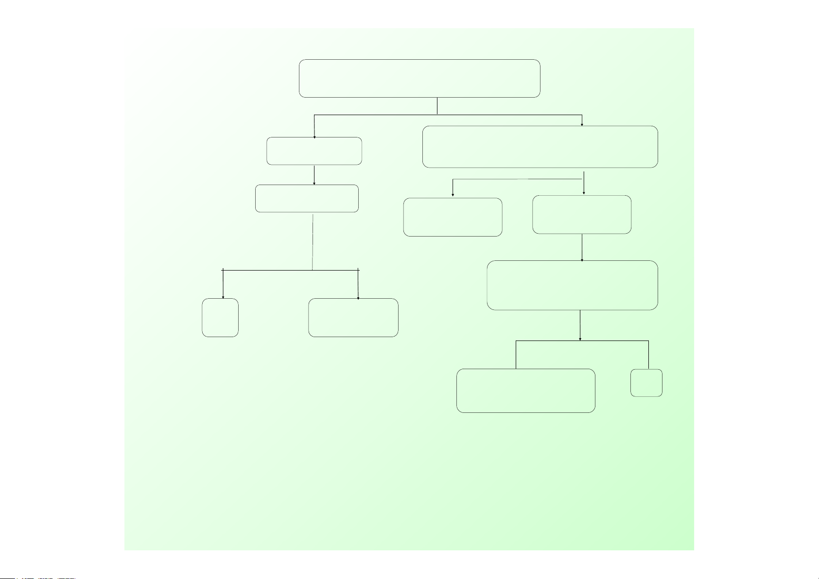
Standby, the board test points TP11 whether 5 V?
main board test point TP5 if have 3.3V
,
test point
TP13 if have 1.25V
?
Normal turn on
Power chip LDO (U1)
whether the work , output
voltage whether 2.5V, or
load short-circuit
After turn on
,
test point TP2 if have
5V ,test point TP2 if have 5V
,
test
point TP9 if have 2.5V
Y
N
Figure 1 Power category
Figure 1 Power category
Figure 1 Power category
Figure 1 Power category
Figure 1 Power category
Figure 1 Power category
Figure 1 Power category
Figure 1 Power category
troubleshooting
troubleshooting
troubleshooting
troubleshooting
troubleshooting
troubleshooting
troubleshooting
troubleshooting
Y
N
OK
check U3 U10
power network
AC input is normal
The replacement
of power
N
check power module
Y
OK
Page 4
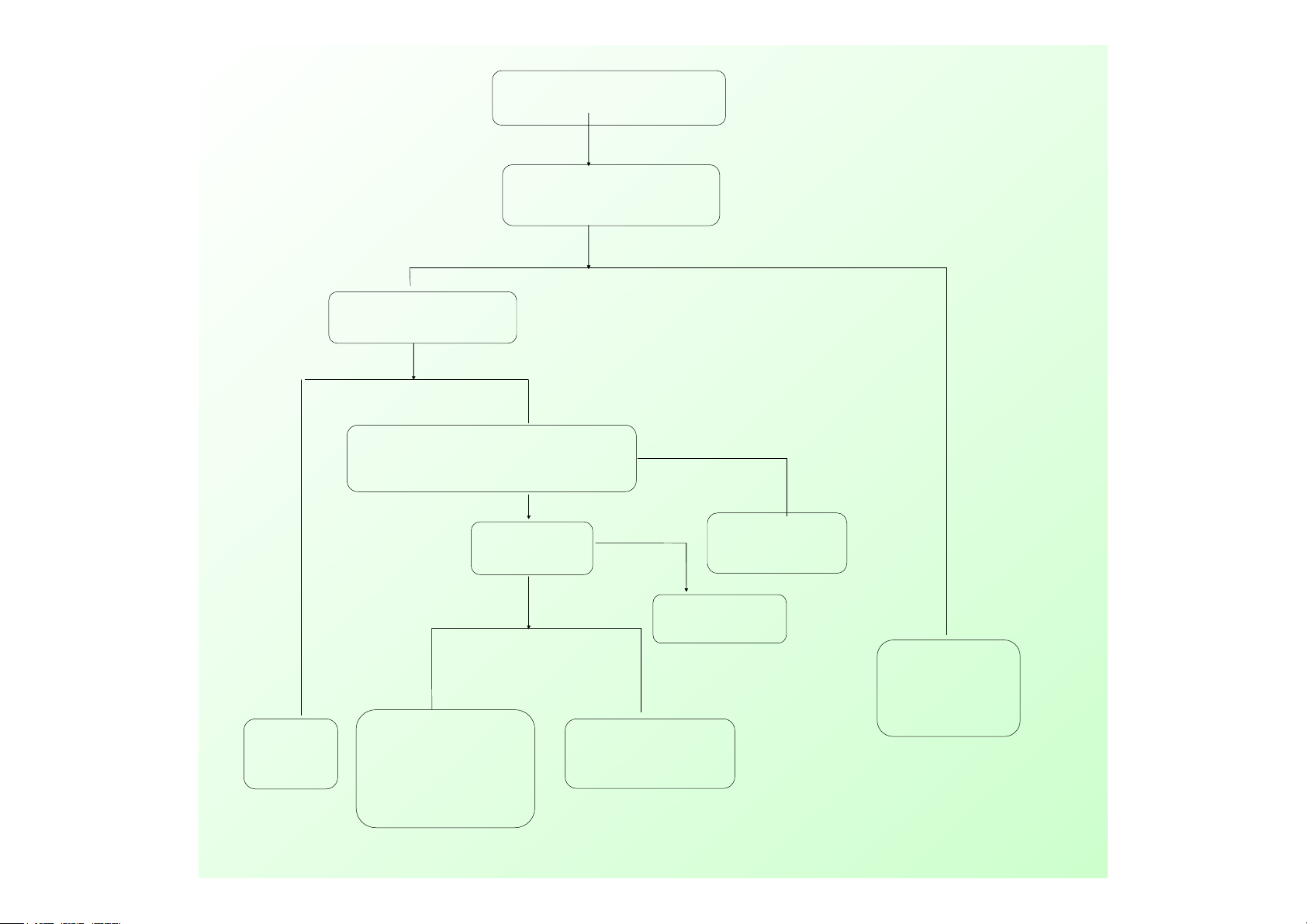
screen noise or
screen black
(
but backlight is on
)
screen driver wire if correct
connect well if OK
change LCD if normal
change screen
driver wire
Y
N
Change LCD
N
Y
check output network
J8 screen driver socket part if normal
Y
check U15
power and clock circuit
IC LVDS output pins if
short,open
Figure 2 shows that
Figure 2 shows that
Figure 2 shows that
Figure 2 shows that
part (
part (
part (
part ( Huaping
Huaping
Huaping
Huaping )
)
)
)
N
Check the power VCCPanel LCD whether 5V
software if match
upgrade matching
software again
N
Change and fix
this part circuit
Page 5
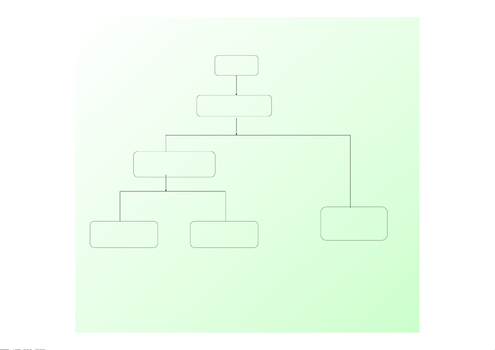
screen black
Check Inverter output voltage
whether normal
?
check the Inverter power
J5 ’ s 1 pin output voltage
whether 5V
?
check & fix power circuit
N
N Y
Y
check & fix this part control
circuit
Inverter
or connected wire
doesn't work
Figure 3 shows that some
Figure 3 shows that some
Figure 3 shows that some
Figure 3 shows that some
(blank screen)
(blank screen)
(blank screen)
(blank screen)
Page 6

No sound
if have audio signal input
AMPLIFICATION power if normal
check
external
audio
equipment
:
AMPLIFICATION
power
circuit
U7
(
TPA3123D2)5/6
pin if have signal input
N
Y
Y
N
volume 、MUTE setup
if normal
Setup
again
J1 、 J2 if have
signal output
Y
N
Check
external
speaker
check & fix
AMPLIFICATION
power circuit
NY
Y
test U22 audio output pin
if have signal output
check & fix U22 to
U7 meddle part
network, include
U23 operation
circuit
check & fix
network
From U22
to U7
Figure 4 audio part (silent)
Figure 4 audio part (silent)
Figure 4 audio part (silent)
Figure 4 audio part (silent)
Y
check power
supply circuit of
U22 ’ s Pin8
And U23 ’ s Pin8
test U22 ’ s Pin1-7
if have signal output
N
N
Page 7

TV doesn ’ t search /no picture
Figure 5 function part
Figure 5 function part
Figure 5 function part
Figure 5 function part
(
ATV
ATV
ATV
ATV
video troubleshooting
video troubleshooting
video troubleshooting
video troubleshooting
)
External RF input signal if normal
N
check & fix
external
RF
equipment
Y
test turner Pin 3
if have 5V
check &
fix this
pin power
network
U12
circuit
Y
N
test tunner pin8 and pin9 if have I2C data
check
I2Cnetwork
(U15 ’ s
205/206pin)
N
Y
test Tunner pin17 if have CVBS signal
N
Check U15
(MSD109BL)
Pin46
and Pin47
and filter
network
U26 failure
change turner
Y
U18 ’ s power supply if normal
test U26 ’ s pin7 input signal if normal
change
Crystal
Oscillator
、
TDP9886 and
U17 ’ s circuit
check U12 ’ s
circuit and
power
supply
network
N
N
Y
Y
Page 8

TV no sound, picture is on
PC AV if have sound
N
Y
refer to “ no sound ”
maintenance
processes
Figure 6 function part
Figure 6 function part
Figure 6 function part
Figure 6 function part
(
ATV no sound
ATV no sound
ATV no sound
ATV no sound
)
test U18 ‘ s pin12 if have audio signal
N
check U15 ’ s
(MSD109BL)
Pin 46/47
and filter
network
Y
change
turner
U18 ’ s power supply if normal
U26 ’ s Pin7 output signal if normal
Y
N
change
Crystal
Oscillator 、
TDP9886 and
U20 ’ s circuit
check U12 ’ s
circuit and
power
supply
network
Y
N
Page 9

TV no search / no picture
Figure 7 function part
Figure 7 function part
Figure 7 function part
Figure 7 function part
(
DTV
DTV
DTV
DTV
video troubleshooting
video troubleshooting
video troubleshooting
video troubleshooting
)
External RF input signal if normal
N
check & fix
external
RF
equipment
Y
test turner pin3 if have 5V
check &
fix this
pin power
network
U12
circuit
Y N
test U26 Pin5 and pin6 if have I2Cdata
check
I2Cnetwork
(U15 circuit,
U15 ’ s
205/206pin)
N
Y
test U5(ZL10353) — TS stream if have signal
?
N
Check U15
(MSD109BL)
networks
Y
test U5 ’ s pin30/31 if have signal input
N
Y
U26 doesn't
work
change turner
U8 ’ s Pin2-4 output voltage if 1.8V
U2 ’ s Pin2-4 output voltage if 3.3V
U5 ’ s power supply circuit if normal?
Check U5
、
crystal etc.
correspond
circuit
Page 10

TV no sound, picture is on
PC AV if have sound
N
Y
refer to “ no sound ”
maintenance
processes
Figure 8 function part
Figure 8 function part
Figure 8 function part
Figure 8 function part
(
DTV no sound
DTV no sound
DTV no sound
DTV no sound
)
test U22 ‘ s pin12 if have audio signal
check U15 ’ s
(MSD109BL)
Pin 74/75
and filter
network
Y
N
check
amplifier
U22 ’ s circuit
Page 11

PC
Picture not
at the center
color less,
color cast
Picture
Jitter
no signal
Automatically
perform
Adjustment order
U15(MSD109BL)
R.G.B input
signal if normal
system setup
wrong
Reset again
Y
N
VS,HS signal
if rules, stability
check VS.HS
circuit
OSD setup
doesn ’ t match
reset again
or input
Mode
not support
check VS.HS
circuit
Y N
Figure 9 function part
Figure 9 function part
Figure 9 function part
Figure 9 function part
(
PC
PC
PC
PC
)
VGA socket
connect if
OK
?
VGA socket
connect if
OK
?
check VGA
input circuit
Y
Y
Page 12

SCART RGB
、
SCART Video
、
Y/C
SCARGT
color less,
color cast
All non-signal
System set
incorrectly
re-reduction
Check SCART RGB
input network
U15 (MSD109BL)
electricity and
crystal Y2
U15 (MSD109BL) of the RGB
input signal is normal
Y N
Figure 10
Figure 10
Figure 10
Figure 10
functional part
functional part
functional part
functional part
(SCART, AV, SV)
(SCART, AV, SV)
(SCART, AV, SV)
(SCART, AV, SV)
SCAR socket
contacts
are good
Page 13

HDMI
no picture
picture on,
no sound
refer to “ power “
maintenance processes
check HDMI
input network
check EEPROM
circuit and
components
U15 (MSD109BL)
related to the HDMI
network
Y
N
Figure 11 function part
Figure 11 function part
Figure 11 function part
Figure 11 function part
(
HDMI
HDMI
HDMI
HDMI
)
PC if have sound
Y
N
refer to “ no
sound ”
maintenance
processes
Page 14

Figure 12 functional part
Figure 12 functional part
Figure 12 functional part
Figure 12 functional part
of PCMCIA cards
of PCMCIA cards
of PCMCIA cards
of PCMCIA cards
CI inserted under the PCMCIA card did
not mention whether CI MODULE INSERTED
Into the menu, read
the information CI
Check power supply VCC-PCMCIA,
check Pin17 and pin51 output
voltage if 5V
CI Module
Inserted
CI Module
Removed
Y
N
Y
N
CI Card insert
Change CI card
Check CI Card
network
CI Card remove
 Loading...