

AKG SR-40 Diversity Owners manual
AKG.WIRELESS
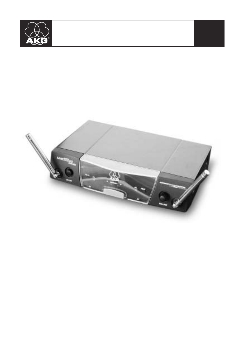
SR 40 diversity
WIRELESS
MICROPHONE
SYSTEM
Bedienungsanleitung. . . . . . . . . . . . S. 2
Bitte vor Inbetriebnahme des Gerätes lesen!
User Instructions. . . . . . . . . . . . . . p. 11
Please read the manual before using the equipment!
Mode d’emploi. . . . . . . . . . . . . . . . p. 19
Veuillez lire cette notice avant d’utiliser le système!
Istruzioni per l’uso. . . . . . . . . . . . . p. 28
Prima di utilizzare l’apparecchio, leggere il manuale
Modo de empleo . . . . . . . . . . . . . . p. 37
¡Sirvase leer el manual antes de utilizar el equipo!
Instruções de uso . . . . . . . . . . . . . p. 46
Favor leia este manual antes de usar o equipamento!
Inhaltsverzeichnis
1 Sicherheit und Umwelt. . . . . . . . . . . . . . . . . . . . . . . . . . . . . . . 2
1.1 Sicherheit . . . . . . . . . . . . . . . . . . . . . . . . . . . . . . . . . . . . 2
1.2 Umwelt . . . . . . . . . . . . . . . . . . . . . . . . . . . . . . . . . . . . . . 3
2 Beschreibung . . . . . . . . . . . . . . . . . . . . . . . . . . . . . . . . . . . . . . 3
2.1 Einleitung. . . . . . . . . . . . . . . . . . . . . . . . . . . . . . . . . . . . . 3
2.2 Lieferumfang . . . . . . . . . . . . . . . . . . . . . . . . . . . . . . . . . . 3
2.3 Empfohlenes Zubehör . . . . . . . . . . . . . . . . . . . . . . . . . . . 4
2.4 Empfänger SR 40 Diversity . . . . . . . . . . . . . . . . . . . . . . . 4
3 Inbetriebnahme . . . . . . . . . . . . . . . . . . . . . . . . . . . . . . . . . . . . . 5
3.1 Empfänger positionieren . . . . . . . . . . . . . . . . . . . . . . . . . 5
3.2 Rackmontage eines Empfängers . . . . . . . . . . . . . . . . . . . 5
3.3 Rackmontage zweier Empfänger nebeneinander . . . . . . . 6
3.4 Empfänger an ein Mischpult anschließen . . . . . . . . . . . . . 6
3.5 Empfänger an einen Verstärker anschließen. . . . . . . . . . . 7
3.6 Empfänger an das Netz anschließen . . . . . . . . . . . . . . . . 7
4 Betriebshinweise . . . . . . . . . . . . . . . . . . . . . . . . . . . . . . . . . . . 7
5 Reinigung. . . . . . . . . . . . . . . . . . . . . . . . . . . . . . . . . . . . . . . . . . 8
6 Fehlerbehebung . . . . . . . . . . . . . . . . . . . . . . . . . . . . . . . . . . . . 8
7 Technische Daten . . . . . . . . . . . . . . . . . . . . . . . . . . . . . . . . . . 10
1 Sicherheit und Umwelt
1.1 Sicherheit
1. Schütten Sie keine Flüssigkeiten auf das Gerät und lassen Sie keine
sonstigen Gegenstände durch die Lüftungsschlitze in das Gerät fallen.
2. Das Gerät darf nur in trockenen Räumen eingesetzt werden.
3. Das Gerät darf nur von autorisiertem Fachpersonal geöffnet, gewartet und repariert werden. Im Inneren des Gehäuses befinden sich
keinerlei Teile, die vom Laien gewartet, repariert oder ausgetauscht
werden können.
4. Prüfen Sie vor Inbetriebnahme des Gerätes, ob die auf dem mitgelieferten Steckernetzteil angegebene Betriebsspannung der
Netzspannung am Einsatzort entspricht.
5. Betreiben Sie das Gerät ausschließlich mit dem mitgelieferten
Wechselspannungsnetzteil mit einer Ausgangsspannung von 12 V
DC. Andere Stromarten und Spannungen könnten das Gerät ernsthaft beschädigen!
6. Brechen Sie den Betrieb der Anlage sofort ab, wenn ein fester
Gegenstand oder Flüssigkeit in das Geräteinnere gelangen sollte.
Ziehen Sie in diesem Fall sofort das Steckernetzteil aus der
Steckdose und lassen Sie das Gerät von unserem Kundendienst
überprüfen.
7. Ziehen Sie das Steckernetzteil bei längerer Nichtverwendung aus
der Steckdose. Bitte beachten Sie, dass bei angestecktem
Seite
2
Sicherheit und Umwelt
Steckernetzteil das Gerät nicht vollständig vom Netz getrennt wird,
wenn Sie es ausschalten.
8. Stellen Sie das Gerät nicht in der Nähe von Wärmequellen wie z. B.
Radiatoren, Heizungsrohren, Verstärkern, usw. auf und setzen Sie es
nicht direkter Sonneneinstrahlung, starker Staub- und
Feuchtigkeitseinwirkung, Regen, Vibrationen oder Schlägen aus.
9. Verlegen Sie zur Vermeidung von Störungen bzw. Einstreuungen
sämtliche Leitungen, speziell die der Mikrofoneingänge, getrennt
von Starkstromleitungen und Netzleitungen. Bei Verlegung in
Schächten oder Kabelkanälen achten Sie darauf, die Übertragungsleitungen in einem separaten Kanal unterzubringen.
10.Reinigen Sie das Gerät nur mit einem feuchten, aber nicht nassen
Tuch. Ziehen Sie unbedingt das Steckernetzteil vorher aus der
Steckdose! Verwenden Sie keinesfalls scharfe oder scheuernde
Reinigungsmittel sowie keine, die Alkohol oder Lösungsmittel enthalten, da diese den Lack sowie die Kunststoffteile beschädigen
könnten.
11.Verwenden Sie die Ladestation nur für die in dieser Bedienungsanleitung beschriebenen Anwendungen. Für Schäden infolge
unsachgemäßer Handhabung oder missbräuchlicher Verwendung
kann AKG keine Haftung übernehmen.
1. Das Steckernetzteil nimmt auch bei ausgeschaltetem Gerät einen
geringen Strom auf. Um Energie zu sparen, ziehen Sie daher das
Steckernetzteil von der Netzsteckdose ab, wenn Sie das Gerät längere Zeit nicht benützen.
2. Wenn Sie das Gerät verschrotten, trennen Sie Gehäuse, Elektronik
und Kabel und entsorgen Sie alle Komponenten gemäß den dafür
geltenden Entsorgungsvorschriften.
2 Beschreibung
Vielen Dank, dass Sie sich für ein Produkt aus dem Hause AKG entschieden haben. Bitte lesen Sie die Bedienungsanleitung aufmerksam
durch, bevor Sie das Gerät benützen, und bewahren Sie die
Bedienungsanleitung sorgfältig auf, damit Sie jederzeit nachschlagen
können. Wir wünschen Ihnen viel Spaß und Erfolg!
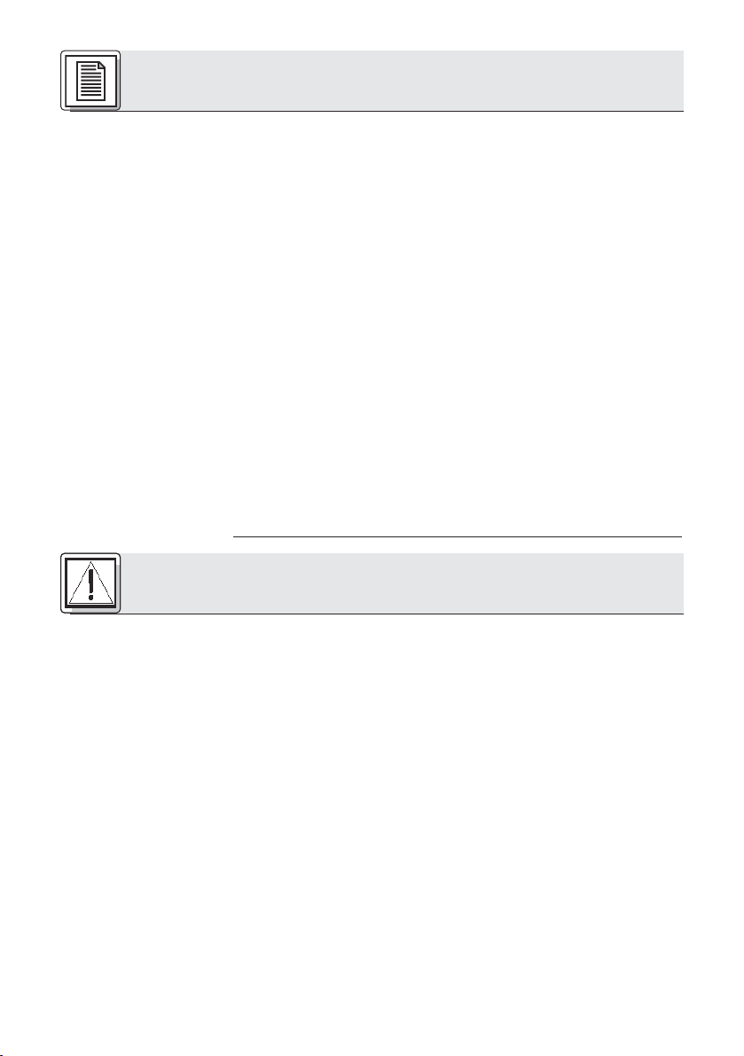
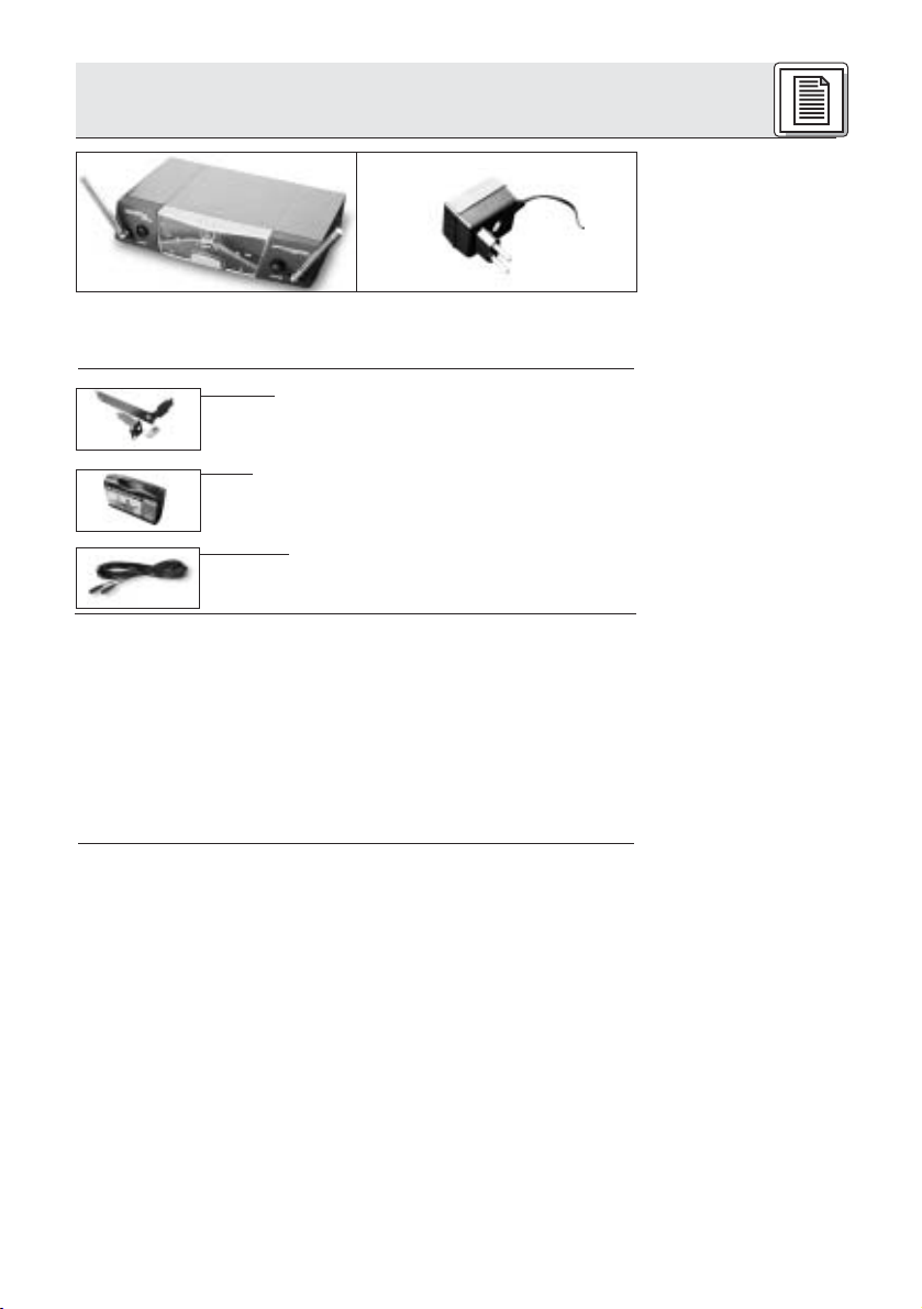
1 x SR 40 diversity 1 Netzgerät, 12 V DC
Kontrollieren Sie bitte, ob die Verpackung alle oben angeführten Teile
enthält. Falls etwas fehlt, wenden Sie sich bitte an Ihren AKG-Händler.
1.2 Umwelt
2.1 Einleitung
2.2 Lieferumfang
3
2 Beschreibung
2.3 Empfohlenes
Zubehör
2.4 Empfänger
SR 40 diversity
2.4.1. Bedien-
elemente an der
Frontplatte
Siehe Fig. 1.
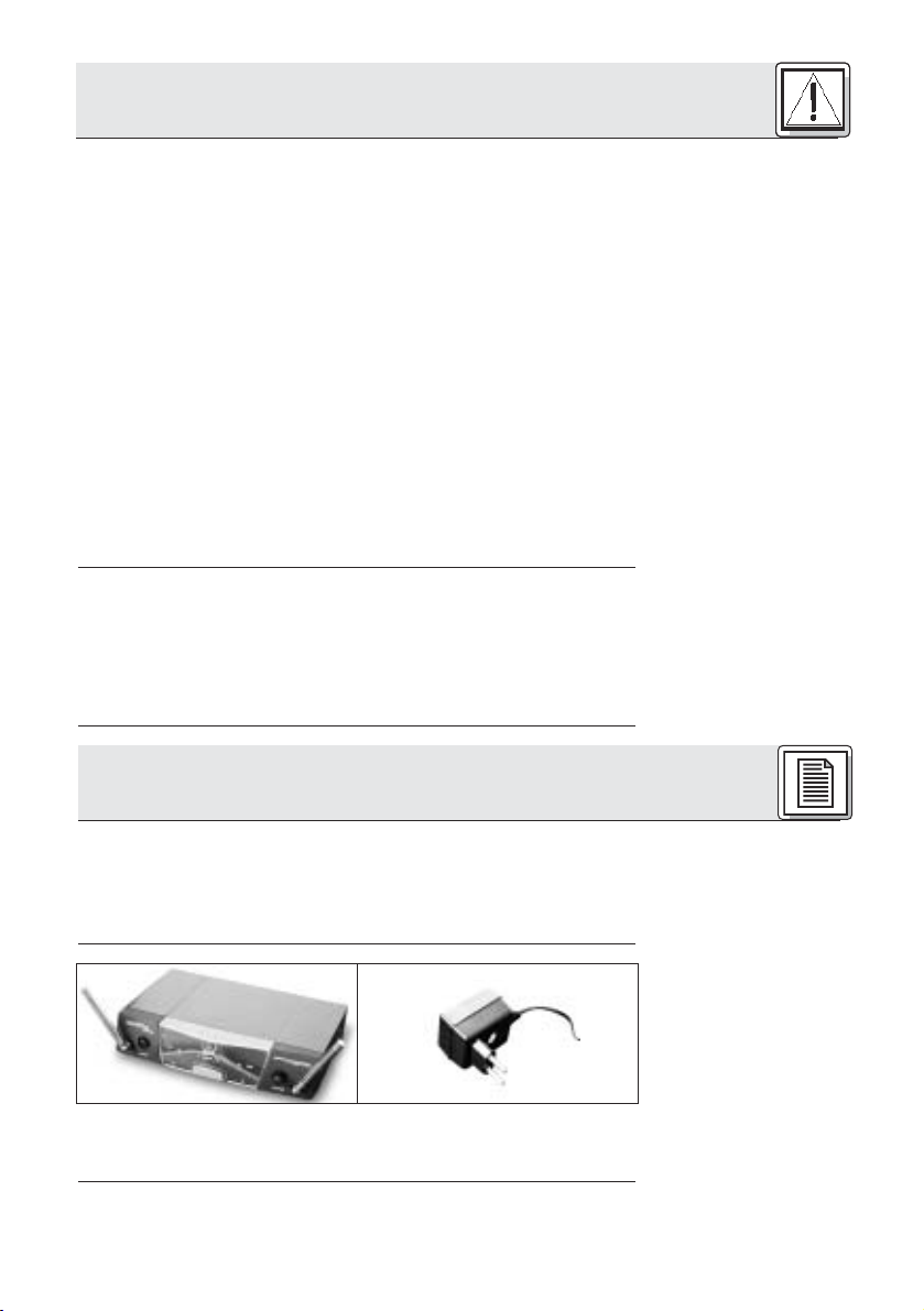
• 19”-Montageset RMU 40/div. für 1 Empfänger
SR 40 diversity
• Kunststoffkoffer CH 40 für ein komplettes
WMS 40 System
• Mikrofonkabel MK 9/10: 10 m 2-polig geschirmtes
Kabel mit XLR-Stecker und XLR-Kupplung
Der SR 40 diversity ist ein stationärer Diversity-Empfänger für alle
Sender des Systems WMS 40 und der microtools Serie. Der SR 40
diversity arbeitet auf einer fixen, quarzstabilisierten Trägerfrequenz im
UHF-Trägerfrequenzbereich von 710 MHz bis 865 MHz und ist für 19”Rackmontage geeignet.
Als Diversity-Empfänger arbeitet der SR 40 diversity mit zwei
Antennen, um das Sendersignal an zwei verschiedenen Punkten empfangen zu können. Die Diversity-Elektronik aktiviert automatisch immer
jene Antenne, die das bessere Signal liefert.
Eine fix eingestellte Rauschsperre ("Squelch") schaltet den Empfänger
bei zu schwachem Empfangssignal ab, so dass die damit verbundenen
Störgeräusche bzw. das Eigenrauschen des Empfängers bei abgeschaltetem Sender nicht hörbar werden.
Antennen: Die Diversity-Elektronik aktiviert automatisch immer
jene Antenne, die das bessere Signal liefert.
ON/OFF: Ein/Aus-Taste. Wenn die DIVERSITY-LEDs A und B
abwechselnd blinken und die RF/MUTE-LED konstant leuchtet, ist
der Empfänger eingeschaltet und empfängt kein Signal.
Wenn die LEDs RF/OK, AF/OK und nur die DIVERSITY-LED A oder
B leuchten, ist der Empfänger eingeschaltet und empfängt ein
Signal.
Wenn Sie den Empfänger ausschalten, erlöschen alle LEDs.
RF/MUTE: Diese LED leuchtet auf, wenn kein Signal empfangen
wird oder der Squelch aktiv ist. In diesen beiden Fällen ist der
Audioausgang stumm geschaltet.
RF/OK: Diese LED zeigt durch Leuchten an, dass die Feldstärke
des Sendersignals an der Empfangsantenne ausreichend ist.
Diversity-LEDs A und B: Zeigen an, welche der beiden
Empfangsantennen gerade aktiv ist.
Farbcode: Die Farbe der AKG-Plakette entspricht der
Trägerfrequenz Ihres Empfängers. Sender und Empfänger mit derselben Trägerfrequenz sind mit derselben Farbe gekennzeichnet.
AF/ON, AF/PEAK: Diese LEDs zeigen den empfangenen
Audiopegel an. Aufleuchten der grünen ON-LED bzw. leichtes
Aufflackern der roten PEAK-LED zeigt optimale Aussteuerung an.
Leuchtet keine der LEDs, ist die Empfindlichkeit des Senders zu
niedrig eingestellt.
Ständiges Leuchten der PEAK-LED zeigt Übersteuerung an.
4
2 Beschreibung
VOLUME: Mit dem VOLUME-Potentiometer können Sie den
Ausgangspegel des Empfängers von Mikrofonpegel bis Linepegel
einstellen und so an die Eingangsempfindlichkeit Ihres Mischpults
oder Verstärkers anpassen.
AUDIO OUT/BALANCED: Symmetrischer Audioausgang an 3-
poliger XLR-Buchse: Diesen Ausgang können Sie z.B. mit einem
Mikrofoneingang eines Mischpults verbinden.
AUDIO OUT/UNBALANCED: Asymmetrischer Audioausgang an
6,3-mm-Mono-Klinkenbuchse. Hier können Sie z.B. einen
Gitarrenverstärker anschließen.
POWER: Versorgungsbuchse zum Anschluss des mitgelieferten
Netzteils.
Zugentlastung für das Versorgungskabel des mitgelieferten
Netzteils.
Typenschild mit Zulassungssymbolen und Frequenzinformationen
(Frequenzen, Frequenz-Sets, Farbcode).
3 Inbetriebnahme
Bevor Sie Ihr WMS 40 in Betrieb nehmen, kontrollieren Sie, ob
Sender und Empfänger auf derselben Frequenz arbeiten. Am leichtesten können Sie dies anhand des Farbcodes überprüfen.
Reflexionen des Sendersignals an Metallteilen, Wänden, Decken, etc.
oder Abschattungen durch menschliche Körper können das direkte
Sendersignal schwächen bzw. auslöschen.
Stellen Sie den Empfänger daher wie folgt auf:
1. Positionieren Sie den Empfänger immer in der Nähe des
Aktionsbereiches (Bühne), achten Sie jedoch auf einen
Mindestabstand zwischen Sender und Empfänger von 3 m bis optimal 5 m.
2. Voraussetzung für optimalen Empfang ist Sichtverbindung zwischen
Sender und Empfänger.
3. Positionieren Sie den Empfänger in einem Abstand von mehr als
1,5 m von großen metallenen Gegenstände, Wänden, Bühnengerüsten, Decken, u.ä.
2.4.2 Bedienelemente an der
Rückseite
Siehe Fig. 2.
Wichtig!
3.1 Empfänger
positionieren
➔
Sie können den Empfänger entweder freistehend aufstellen oder mit Hilfe
des optionalen Montagesets RMU 40/div. in einem 19”-Rack montieren.
1. Schrauben Sie die vier Gummifüße von der Unterseite des
Empfängers ab.
2. Schrauben Sie die beiden Befestigungsschrauben von jeder der
beiden Seitenwände ab.
3.2 Rackmontage
eines Empfängers
Siehe Fig. 3.
5
3 Inbetriebnahme
3. Befestigen Sie mit den Schrauben den kurzen Montagewinkel
an der einen Seitenwand und den langen Montagewinkel aus dem
optionalen Montageset RMU 40/div. an der anderen Seitenwand.
4. Befestigen Sie den Empfänger im Rack.
3.3 Rackmontage
zweier Empfänger
nebeneinander
Siehe Fig. 4.
Hinweis:
3.4 Empfänger an
ein Mischpult
anschließen
Siehe Fig. 5.
Um zwei Empfänger nebeneinander in derselben Rackebene zu montieren, benötigen Sie zwei optionale Montagesets RMU 40/div.
1. Schrauben Sie die vier Gummifüße von der Unterseite beider
Empfänger ab und nehmen Sie die Schrauben aus den
Gummifüßen heraus.
2. Schrauben Sie die beiden Befestigungsschrauben von der rechten Seitenwand des einen Empfängers und von der linken Seitenwand
des anderen Empfängers ab.
3. Ziehen Sie die Plastikabdeckungen von jenen Seitenwänden ab, von
denen Sie die Befestigungsschrauben nicht abgeschraubt haben.
4. Schieben Sie einen Verbindungsteil durch je einen freien Schlitz
in der Seitenwand des ersten Empfängers, so dass das
Befestigungsloch im Verbindungsteil mit dem Gewindeloch in der
Unterseite des Empfängers fluchtet.
5. Fixieren Sie die beiden Verbindungsteile mit zwei der Schrauben
(aus den Gummifüßen) am ersten Empfänger.
6. Verbinden Sie die beiden Empfänger, indem Sie die Verbindungsteile
am ersten Empfänger durch die freien Schlitze in der Seitenwand
des zweiten Empfängers schieben, bis das Befestigungsloch in beiden Verbindungsteilen mit dem entsprechenden Gewindeloch in
der Unterseite des zweiten Empfängers fluchtet.
7. Fixieren Sie die Verbindungsteile mit zwei der Schrauben aus
den Gummifüßen am zweiten Empfänger.
8. Schrauben Sie mit je zwei der Schrauben aus den Seitenwänden
je einen kurzen Montagewinkel an die äussere Seitenwand jedes
Empfängers.
9. Befestigen Sie die Empfänger im Rack.
Bewahren Sie die restlichen Schrauben für spätere Verwendung
gut auf.
Sie haben zwei Möglichkeiten, den Empfänger an ein Mischpult anzuschließen:
A. Verbinden Sie mittels eines XLR-Kabels die BALANCED-Buchse
an der Rückseite des Empfängers mit einem symmetrischen
Mikrofoneingang (XLR-Buchse) am Mischpult. Drehen Sie den
VOLUME-Regler an der Fontplatte des Empfängers ganz nach links
(Mikrofonpegel).
Siehe Fig. 6.
Wichtig!
➔
6
B. Verbinden Sie mittels eines 6,3 mm-Klinkenkabels die
UNBALANCED-Buchse an der Rückseite des Empfängers mit
einem asymmetrischen LINE-Eingang (6,3 mm-Klinkenbuchse) am
Mischpult. Drehen Sie den VOLUME-Regler an der Fontplatte des
Empfängers ganz nach rechts (Linepegel).
Benützen Sie nie beide Ausgangsbuchsen gleichzeitig! Dies kann
zu Pegelverlust und erhöhtem Rauschen führen.
3 Inbetriebnahme
1. Verbinden Sie mittels eines 6,3 mm-Klinkenkabels die
UNBALANCED-Buchse an der Rückseite des Empfängers mit
einem asymmetrischen LINE-Eingang (6,3 mm-Klinkenbuchse) am
Verstärker.
2. Drehen Sie den VOLUME-Regler am Empfänger ganz nach rechts
(Linepegel).
1. Kontrollieren Sie, ob die am mitgelieferten Netzadapter angege-
bene Netzspannung mit der Netzspannung am Einsatzort übereinstimmt. Der Betrieb des Netzadapters an einer anderen Netz-
spannung kann zu irreparablen Schäden am Gerät führen.
2. Stecken Sie das Versorgungskabel des mitgelieferten
Netzadapters an die POWER-Buchse an der Rückseite des
Empfängers an.
3. Legen Sie das Versorgungskabel zu einer Schlaufe, stecken Sie die
Schlaufe von oben durch die Zugentlastung und legen Sie sie um
den Haken der Zugentlastung . Ziehen Sie das Kabel fest.
4. Stecken Sie den Netzadapter an eine Netzsteckdose an.
5. Schalten Sie den Empfänger ein, indem Sie die ON/OFF-Taste an
der Frontplatte drücken.
Wenn der Sender nicht eingeschaltet ist oder aus anderen Gründen
(z.B. Abschattungen) kein Sendersignal empfangen wird, leuchtet
die RF/MUTE-LED auf und blinken die DIVERSITY-LEDs A und B
abwechselnd.
Wenn ein Sendersignal empfangen wird, leuchten die LEDs RF/OK,
AF/OK und eine der beiden DIVERSITY-LEDs A oder B auf.
4 Betriebshinweise
1. Schalten Sie den Sender ein. (Siehe auch Bedienungsanleitung des
Senders.)
3.5 Empfänger an
einen Verstärker
anschließen
Siehe Fig. 7.
3.6 Empfänger an
das Netz anschließen
Siehe Fig. 8.
➔
2. Richten Sie beide Antennen des Empfängers ca. 45° nach oben und
vom Empfänger weg.
3. Schalten Sie den Empfänger ein und kontrollieren Sie die Stellung
des VOLUME-Reglers:
Empfänger mit Mikrofoneingang verbunden = linker Anschlag,
Empfänger mit Line-Eingang verbunden = rechter Anschlag.
4. Schalten Sie Ihre PA-Anlage bzw. Ihren Verstärker ein.
5. Stellen Sie die Lautstärke der PA-Anlage bzw. des Verstärkers wie in
deren Bedienungsanleitung beschrieben oder nach Gehör ein.
6. Schreiten Sie den Bereich ab, in dem Sie den Sender einsetzen werden. Achten Sie dabei auf Stellen, wo die Feldstärke absinkt und
daher der Empfang kurzzeitig gestört wird (“Dropouts”).
Solche Dropouts können Sie beheben, indem Sie den Empfänger
anders positionieren. Hat dies keinen Erfolg, vermeiden Sie diese
kritischen Stellen.
7
4 Betriebshinweise
7. Achten Sie darauf, dass zwischen Sender und Empfänger immer
eine Sichtverbindung besteht.
8. Wenn am Empfänger die die RF/OK-LED erlischt, bedeutet dies,
dass kein Signal empfangen wird oder der Squelch aktiv ist.
Schalten Sie den Sender ein und/oder gehen Sie näher zum
Empfänger, bis die RF/OK-LED wieder aufleuchtet.
9. Wenn am Empänger die AF/PEAK-LED häufig auleuchtet oder konstant zu leuchten beginnt, ist das Sendersignal zu stark.
Drehen Sie den GAIN-Regler am Sender soweit zurück, dass die
AF/PEAK-LED nur mehr gelegentlich kurz aufleuchtet.
5 Reinigung
Zum Reinigen der Oberflächen des Empfängers verwenden Sie am
besten ein mit Wasser befeuchtetes weiches Tuch.
6 Fehlerbehebung
Kein Ton.
8
Fehler
Mögliche Ursache
1. Netzadapter ist nicht an
Empfänger bzw. Netzsteckdose angeschlossen.
2. Empfänger ist ausgeschaltet.
3. Empfänger ist nicht an
Mischpult oder Verstärker
angeschlossen.
4. VOLUME-Regler am
Empfänger steht auf Null.
5. Mikrofon bzw. Instrument
ist nicht am Taschensender
angeschlossen.
6. Sender hat anderen
Farbcode als Empfänger.
7. Ein/Ausschalter des
Senders steht auf ”OFF”
oder ”MUTE”.
8. Batterien falsch im Sender
eingelegt.
9. Senderbatterien sind leer.
Behebung
1. Netzadapter an Empfänger
und Netz anstecken.
2. Empfänger mitttels
ON/OFF-Taste einschalten.
3. Empfängerausgang mit
Mischpult- oder Verstärkereingang verbinden.
4. VOLUME-Regler aufdrehen.
5. Mikrofon bzw. Instrument
mit Audioeingang des
Taschensenders verbinden.
6. Sender mit gleichem
Farcode wie Empfänger
verwenden.
7. Ein/Ausschalter des
Senders auf ”ON” stellen.
8. Batterien entsprechend
Polaritätskennzeichnung
(+/-) im Batteriefach neu
einlegen.
9. Neue Batterien in den
Sender einlegen.

6 Fehlerbehebung
Fehler
Kein Ton.
Rauschen, Krachen, unerwünschte Signale.
Verzerrungen.
Mögliche Ursache
10.Sender ist zu weit vom
Empfänger entfernt.
11.Hindernisse zwischen
Sender und Empfänger.
12.Keine Sichtverbindung zwischen Sender und
Empfänger.
13.Empfänger zu nahe bei
metallischen Gegenständen.
1. Antennenposition.
2. Störungen durch andere
Drahtlosanlagen,
Fernsehen, Radio,
Funkgeräte oder schadhafte Elektrogeräte oder
-installation.
1. Eingangspegelregler am
Sender zu hoch oder zu
niedrig eingestellt.
2. Störungen durch andere
Drahtlosanlagen,
Fernsehen, Radio,
Funkgeräte oder schadhafte Elektrogeräte oder
-installation.
Behebung
10.Näher zum Empfänger
gehen.
11.Hindernisse entfernen.
12.Stellen, von denen aus der
Empfänger nicht sichtbar
ist, vermeiden.
13.Störende Gegenstände entfernen oder Empfänger
weiter weg aufstellen.
1. Empfänger an einer anderen Stelle aufstellen.
2. Störende bzw. schadhafte
Geräte ausschalten oder
WMS 40 mit anderer
Trägerfrequenz verwenden;
Elektroinstallation überprüfen lassen.
1. Eingangspegelregler soweit
zurückdrehen oder aufdrehen, dass Verzerrungen
verschwinden.
2. Störende bzw. schadhafte
Geräte ausschalten oder
WMS 40 mit anderer
Trägerfrequenz verwenden;
Elektroinstallation überprüfen lassen.
Kurzzeitiger Tonausfall
(”Dropouts”) an manchen
Stellen des Aktionsbereichs.
1. Antennenposition.
1. Empfänger an einer anderen Stelle aufstellen. Falls
Dropouts bestehen bleiben,
kritische Stellen markieren
und vermeiden.
9

7 Technische Daten
Trägerfrequenz 710 - 865 MHz
Modulation FM
Audioübertragungsbandbreite 40 - 20.000 Hz
Frequenzstabilität (-10°C bis +50°C) ±15 kHz
Klirrfaktor bei 1 kHz typ. 0,8%
Kompander eingebaut
Signal/Rauschabstand typ. 108 dB(A)
Stromaufnahme 110 ±15 mA
Spannungsversorgung 12 bis 16 V DC
Eingangsempfindlichkeit typ. -95 dBm
Audioausgang XLR symm. und 6,3 mm-Klinke asymm.: regelbar von
Abmessungen (BxTxH) 200 x 135 x 42 mm
Nettogewicht 470 g
Dieses Produkt entspricht den Normen EN60065:1998, EN301 489-9 v.1.1.1 (09-2000) und
EN300 422-2 v.1.1.1 (07-2000).
Mikrofon- bis Linepegel: max. 2 V eff.
10

Table of Contents
FCC Statement . . . . . . . . . . . . . . . . . . . . . . . . . . . . . . . . . . . . . . 11
1 Safety and Environment. . . . . . . . . . . . . . . . . . . . . . . . . . . . . 12
1.1 Safety . . . . . . . . . . . . . . . . . . . . . . . . . . . . . . . . . . . . . . 12
1.2 Environment. . . . . . . . . . . . . . . . . . . . . . . . . . . . . . . . . . 12
2 Description . . . . . . . . . . . . . . . . . . . . . . . . . . . . . . . . . . . . . . . 12
2.1 Introduction . . . . . . . . . . . . . . . . . . . . . . . . . . . . . . . . . . 12
2.2 Unpacking . . . . . . . . . . . . . . . . . . . . . . . . . . . . . . . . . . . 12
2.3 Optional Accessories . . . . . . . . . . . . . . . . . . . . . . . . . . . 13
2.4 SR 40 diversity Receiver . . . . . . . . . . . . . . . . . . . . . . . . 13
3 Setting Up . . . . . . . . . . . . . . . . . . . . . . . . . . . . . . . . . . . . . . . . 14
3.1 Placing the Receiver . . . . . . . . . . . . . . . . . . . . . . . . . . . 14
3.2 Rack Mounting a Single Receiver. . . . . . . . . . . . . . . . . . 15
3.3 Rack Mounting Two Receivers Side by Side. . . . . . . . . . 15
3.4 Connecting the Receiver to a Mixer . . . . . . . . . . . . . . . . 15
3.5 Connecting the Receiver to an Amplifier . . . . . . . . . . . . 16
3.6 Connecting the Receiver to Power . . . . . . . . . . . . . . . . . 16
4 Operating Notes . . . . . . . . . . . . . . . . . . . . . . . . . . . . . . . . . . . 16
5 Cleaning . . . . . . . . . . . . . . . . . . . . . . . . . . . . . . . . . . . . . . . . . . 17
6 Troubleshooting. . . . . . . . . . . . . . . . . . . . . . . . . . . . . . . . . . . . 17
7 Specifications . . . . . . . . . . . . . . . . . . . . . . . . . . . . . . . . . . . . . 18
FCC Statement
This equipment has been tested and found to comply with the limits for a Class B digital device,
pursuant to Parts 74, 15, and 90 of the FCC Rules. These limits are designed to provide reasonable protection against harmful interference in a residential installation. This equipment generates,
uses, and can radiate radio frequency energy and, if not installed and used in accordance with the
instructions, may cause harmful interference to radio communications. However, there is no guarantee that interference will not occur in a particular installation. If this equipment does cause
harmful interference to radio or television reception, which can be determined by turning the
equipment off and on, the user is encouraged to try to correct the interference by one or more of
the following measures:
• Reorient or relocate the receiving antenna.
• Increase the separation between the equipment and the receiver.
• Connect the equipment into an outlet on a circuit different from that to which the receiver is
connected.
• Consult the dealer or an experienced radio/TV technician for help.
Page
Shielded cables and I/O cords must be used for this equipment to comply with the relevant FCC
regulations.
Changes or modifications not expressly approved in writing by AKG Acoustics may void the user’s
authority to operate this equipment.
This device complies with Part 15 of the FCC Rules. Operation is subject to the following two conditions: (1) this device may not cause harmful interference, and (2) this device must accept any
interference received, including interference that may cause undesired operation.
11

1 Safety and Environment
1.1 Safety
1. Do not spill any liquids on the equipment and do not drop any objects through the ventilation slots in the equipment.
2. The equipment may be used in dry rooms only.
3. The equipment may be opened, serviced, and repaired by authorized personnel only. the equipment contains no user-serviceable
parts.
4. Before connecting the equipment to power, check that the AC mains
voltage stated on the supplied AC adapter is identical to the AC
mains voltage available where you will use the equipment.
5. Operate the equipment with the supplied 12-V AC adapter. Using
adapters with a DC output and/or a different output voltage may
cause serious damage to the unit.
6. If any solid object or liquid penetrates into the equipment, shut
down the sound system immediately. Disconnect the AC adapter
from the power outlet immediately and have the equipment checked
by AKG service personnel.
7. If you will not use the equipment for a long period of time, disconnect the AC adapter from the power outlet. Please note that the
equipment will not be fully isolated from power when you set the
power switch to OFF.
8. Do not place the equipment near heat sources such as radiators,
heating ducts, or amplifiers, etc. and do not expose it to direct sunlight, excessive dust, moisture, rain, mechanical vibrations, or
shock.
9. To avoid hum or interference, route all audio lines, particularly those
connected to the microphone inputs, away from power lines of any
type. If you use cable ducts, be sure to use separate ducts for the
audio lines.
10.Clean the equipment with a moistened (not wet) cloth only. Be sure
to disconnect the AC adapter from the power outlet before cleaning
the equipment! Never use caustic or scouring cleaners or cleaning
agents containing alcohol or solvents since these may damage the
enamel and plastic parts.
11.Use the equipment for the applications described in this manual
only. AKG cannot accept any liability for damages resulting from
improper handling or misuse.
1.2 Environment
2 Description
2.1 Introduction
12
1. The AC adapter will draw a small amount of current even when the
equipment is switched off. To save energy, disconnect the AC adapter from the power outlet if you will leave the equipment unused for
a long period of time.
2. When scrapping the equipment, separate the case, circuit boards,
and cables, and dispose of all components in accordance with local
waste disposal rules.
Thank you for purchasing an AKG product. This Manual contains
important instructions for setting up and operating your equipment.
Please take a few minutes to read the instructions below carefully be-
fore operating the equipment. Please keep the Manual for future
reference. Have fun and impress your audience!
2 Description
1 SR 40 diversity 1 AC adapter, 12 V DC
Please check that the packaging contains all system components as
listed above. If anything is missing, please contact your AKG dealer.
2.2 Unpacking
• RMU 40/div. 19" rack mounting kit for one
SR 40 diversity receiver
• CH 40 plastic carrying case for one complete
WMS 40 system.
• MK 9/10 microphone cable: 10-m (30-ft.)
2-conductor shielded cable
w/male and female XLR connectors
The SR 40 diversity is a stationary diversity receiver for use with all
WMS 40 and microtools Series transmitters. The SR 40 operates on
one fixed, quartz stabilized frequency in the 710 MHz to 865 MHz UHF
carrier frequency range and features a half-rack case.
The SR 40 diversity is a diversity receiver and uses two antennas in
order to receive the transmitter signal at two different spots. The diversity electronics will automatically activate the antenna that delivers
the better signal.
A preset squelch will mute the receiver if the received signal is too weak
so the related noise or the self-noise of the receiver will not become
audible when the transmitter is switched OFF.
Antennas: The diversity circuit will automatically activate the an-
tenna that provides the better signal.
ON/OFF: On/off pushbutton switch. If the DIVERSITY LEDs A and
B flash alternately and the RF/MUTE LED lights constantly, the
receiver is ON but receives no signal.
If the RF/OK, AF/OK, and only one of the two DIVERSITY LEDs
illuminate, the receiver is ON and receives signal.
When you switch the receiver OFF, all LEDs will extinguish.
RF/MUTE: This LED illuminates to indicate that no signal is being
received or the squelch is active. In both cases, the audio output
will be muted automatically.
RF/OK: This LED illuminates to indicate that the received field
strength of the transmitter signal is high enough to drive the input.
DIVERSITY LEDs A and B: Indicate which of the two receiving
antennas is active at any time.
Color code: The color of the AKG label indicates the carrier fre-
quency of your receiver. Transmitters and receivers tuned to the
same frequency are marked with identical colors.
2.3 Optional
Accessories
2.4 SR 40 diversity
Receiver
2.4.1 Front Panel
Controls
Refer to fig. 1.
13
2 Description
AF/ON, AF/PEAK: These two LEDs indicate the received audio
level. The green ON LED illuminating and the red PEAK LED
flashing occasionally indicate optimum modulation.
If none of the LEDs illuminates, the gain setting on the transmitter
is too low.
The PEAK LED lighting constantly indicates overmodulation.
VOLUME: This rotary control adjusts the receiver’s output level
from microphone to line level for matching to the input sensitivity
of your mixer or amplifier.
2.4.2 Rear Panel
Controls
Refer to fig. 2.
3 Setting Up
➔
Important!
3.1 Placing the
Receiver
AUDIO OUT/BALANCED: Balanced 3-pin XLR audio output for
connecting to, e.g., a microphone input on the mixing console.
AUDIO OUT/UNBALANCED: Unbalanced audio output on a 1/4"
TS jack for connecting to, e.g., a guitar amplifier.
POWER: Input connector for the supplied AC adapter.
Strain Relief for the feeder cable of the supplied AC adapter.
Type plate with approval marks and frequency information
(frequencies, frequency sets, color code).
Prior to setting up your WMS 40, check that the transmitter and
receiver are tuned to the same frequency. The easiest way to do
this is to compare the color codes on the transmitter and receiver.
Reflections off metal parts, walls, ceilings, etc. or the shadow effects of
musicians and other people may weaken or cancel the direct transmitter signal.
For best results, place the receiver as follows:
14
1. Place the receiver near the performance area (stage). Make sure,
though, that the transmitter will never get any closer to the receiver
than 10 ft (3 m). Optimum separation is 16 ft. (5 m).
2. Check that you can see the receiver from where you will be using the
transmitter.
3. Place the receiver at least 5 ft. (1.5 m) away from any big metal
objects, walls, scaffolding, ceilings, etc.
You can either use the receiver freestanding or mount it in a 19" rack
using the optional RMU 40/div. rack mounting kit.

3 Setting Up
1. Unscrew the four rubber feet from the receiver bottom panel.
2. Unscrew the two fixing screws from each side panel.
3. Use the fixing screws to screw the short bracket to one side
panel and the long bracket to the other side panel. The brackets
are contained in the RMU 40/div. rack mounting kit.
4. Install the receiver in your rack.
To mount two receivers side by side in the same rack slot, you will need
two optional RMU 40/div. rack mounting kits.
1. Unscrew the four rubber feet from each receiver's bottom panel
and remove the screws from the rubber feet .
2. Unscrew the two fixing screws from the right-hand side panel of
one receiver and from the left-hand side panel of the other receiver.
3. Remove the plastic covers from the side panels with the fixing
screws still on.
4. Insert one connecting strip into each free slot in the side panel of
the first receiver, making sure to align the hole in each connecting
strip with the appropriate threaded hole in the receiver bottom
panel.
5. Fix the two connecting strips on the first receiver using two of the
screws you removed from the rubber feet.
6. To join the two receivers, slide the connecting strips on the first
receiver through the free slots in the side panel of the second receiver. Make sure to align the hole in each connecting strip with the
appropriate threaded hole in the bottom panel of the second
receiver.
7. Fix the two connecting strips on the second receiver using two of
the screws you removed from the rubber feet.
8. Screw a short bracket to the outer side panel of each receiver
using for each bracket two of the screws you removed from the
receiver side panels.
9. Install the receivers in your rack.
3.2 Rack Mounting
a Single Receiver
Refer to fig.3.
3.3 Rack Mounting
Two Receivers
Side by Side
Refer to fig. 4.
Be sure to keep the remaining screws for later use.
You can connect the receiver to a mixer in one of two ways:
A. Use a standard XLR cable to connect the BALANCED connector
on the receiver rear panel to a balanced XLR microphone input on
the mixer. Turn the VOLUME control on the receiver front panel all
the way CCW to set the receiver output to microphone level.
B. Use a standard 1/4" jack cable to connect the UNBALANCED jack
on the receiver rear panel to an unbalanced 1/4" line input jack
on the mixer. Turn the VOLUME control on the receiver front panel
all the way CW to set the receiver output to line level.
Never use the two audio outputs simultaneously! This may cause
signal loss or increased noise.
Note:
3.4 Connecting the
Receiver to a Mixer
Refer to fig. 5.
Refer to fig. 6.
Important:
➔
15
3 Setting Up
3.5 Connecting the
Receiver to an
Amplifier
Refer to fig. 7.
3.6 Connecting
➔
the Receiver to
Power
Refer to fig. 8.
4 Operating Notes
1. Use a standard 1/4" jack cable to connect the UNBALANCED
jack on the receiver rear panel to an unbalanced 1/4" line input
jack on the amplifier.
2. Turn the VOLUME control on the receiver front panel all the way CW
to set the receiver output to line level.
1. Check that the AC mains voltage stated on the supplied AC
adapter is identical to the AC mains voltage available where you
will use your equipment. Using the AC adapter with a different AC
voltage may cause irreparable damage to the unit.
2. Plug the feeder cable on the supplied AC adapter into the
POWER socket on the receiver rear panel.
3. Bend part of the feeder cable into a small bight, pass the bight
through the strain relief from above, and place the end of the
bight snugly against the hook on the strain relief . Tighten the
cable.
4. Plug the AC adapter into a convenient power outlet .
5. Press the front panel POWER switch to switch power to the receiver
ON.
If the transmitter is OFF or no transmitter signal arrives at the
receiver due to other causes such as shadow effects, the RF/MUTE
LED will illuminate and the DIVERSITY LEDs A and B will flash alternately.
If a transmitter signal is received, the RF/OK and AF/OK LEDs as
well as one of the two DIVERSITY LEDs A or B will illuminate.
1. Switch power to the transmitter ON. (Refer to the transmitter
manual.)
16
2. Point the antennas approx. 45° upward and away from the receiver.
3. Switch power to the receiver ON and check the position of the
VOLUME control:
Receiver connected to microphone input -> full CCW
Receiver connected to line input -> full CW
4. Switch power to your sound system or amplifier on.
5. Set the levels on your mixer or amplifier referring to the appropriate
instruction manual or by ear.
6. Move the transmitter around the area where you will use the system
to check the area for "dead spots", i.e., places where the field
strength seems to drop and reception deteriorates.
If you find any dead spots, try to eliminate them by repositioning the
receiver. If this does not help, avoid the dead spots.
7. Make sure there will always be a direct line of sight from the transmitter to the receiver.
4 Operating Notes
8. The RF/OK LED on the receiver going out means no signal is received or the squelch is active.
Remedies: Switch power to the transmitter ON and/or move closer
to the receiver to a point where the RF/OK LED will come back on.
9. The AF/PEAK LED on the receiver flashing frequently or glowing
constantly means the transmitter signal is too strong.
Turn the GAIN control on the transmitter CCW to the point that the
AF/PEAK LED will only flash occasionally.
5 Cleaning
Use a soft cloth moistened with water to clean the receiver surfaces.
6 Troubleshooting
No sound.
Problem
Possible Cause
1. AC adapter is not connected to receiver and/or power
outlet.
2. Receiver is OFF.
3. Receiver is not connected
to mixer or amplifier.
4. VOLUME control on receiver is at zero.
5. Microphone or instrument
is not connected to bodypack transmitter.
6. Transmitter and receiver
color codes are not
identical.
7. Transmitter on/off switch is
at “OFF” or “MUTE”.
8. Transmitter batteries are
not inserted properly.
9. Transmitter batteries dead.
10.Transmitter is too far away
from receiver.
11.Obstructions between
transmitter and receiver.
12.Receiver is invisible from
transmitter location.
13.Receiver is too close to
metal objects.
Remedy
1. Connect AC adapter to
receiver and/or power outlet.
2. Push POWER switch to
switch receiver ON.
3. Connect receiver output to
mixer or amplifier input.
4. Turn up VOLUME control.
5. Connect microphone or
instrument to audio input
on bodypack.
6. Use receiver and transmitter with identical color
codes.
7. Set transmitter on/off
switch to “ON”.
8. Insert batteries conforming
to “+” and “-” marks.
9. Replace batteries.
10.Move closer to receiver.
11.Remove obstructions from
between transmitter and
receiver.
12.Avoid spots where you
cannot see receiver.
13.Move receiver away from or
remove interfering objects.
17
6 Troubleshooting
Problem
Noise, crackling, unwanted
signals.
Distortion.
Momentary loss of sound
(“dropouts”) at some locations
within performance area.
Possible Cause
1. Antenna location.
2. Interference from other
wireless systems, TV, radio,
CB radios, or defective
electrical appliances or
installations.
1. GAIN control on transmitter
is set too high or too low.
2. Interference from other
wireless systems, TV, radio,
CB radios, or defective
electrical appliances or
installations.
1. Antenna location.
Remedy
1. Relocate receiver.
2. Switch off interference
sources or defective appliances or use a WMS 40
tuned to a different frequency; have electrical
installation checked.
1. Turn GAIN control down or
up just enough to stop the
distortion.
2. Switch off interference
sources or defective appliances or use a WMS 40
tuned to a different frequency; have electrical
installation checked.
1. Relocate receiver. If dead
spots persist, mark and
avoid them.
7 Specifications
Carrier frequency range 710 to 865 MHz
Modulation FM
Audio bandwidth 40 to 20,000 Hz
Frequency stability (-10°C to +50°C) ±15 kHz
T.H.D. at 1 kHz 0.8% typ.
Compander integrated
Signal/noise ratio 108 dB(A) typ.
Current consumption 110 ±15 mA
Power requirement 12 to 16 V DC
Input sensitivity -95 dBm typ.
Audio outputs XLR bal. and unbal. 1/4” jack: adjustable from mic to line
Size (WxDxH) 200 x 135 x 42 mm (8 x 5.3 x 1.7 in.)
Net weight 470 g (16.6 oz.)
This product complies with the following standards: EN60065:1998, EN301 489-9 v.1.1.1
(09-2000), and EN300 422-2 v.1.1.1 (07-2000).
level: 2 Vrms max.
18
 Loading...