

PT 40
bodypack transmitter
Bedienungshinweise . . . . . . . . . . . . . . . . . . S. 2
Bitte vor Inbetriebnahme des Gerätes lesen!
User Instructions . . . . . . . . . . . . . . . . . . . . p. 10
Please read the manual before using the equipment!
Mode d’emploi . . . . . . . . . . . . . . . . . . . . . . p. 18
Veuillez lire cette notice avant d’utiliser le système!
Istruzioni per l’uso . . . . . . . . . . . . . . . . . . . p. 26
Prima di utilizzare l’apparecchio, leggere il manuale!
Modo de empleo . . . . . . . . . . . . . . . . . . . . p. 34
Antes de utilizar el equipo, sírvase leer el manual!
Instruções de uso . . . . . . . . . . . . . . . . . . . p. 42
Favor leia este manual antes de usar o equipamen
to!
WMS40
wireless microphone system
1 Sicherheit und
Umwelt
1.1 Sicherheit
1. Setzen Sie das Gerät nicht direkter
Sonneneinstrahlung, starker Staubund Feuchtigkeitseinwirkung, Regen,
Vibrationen oder Schlägen aus.
1.2 Umwelt
1. Entsorgen Sie verbrauchte Batterien
und Akkus immer gemäß den jeweils
geltenden Entsorgungsvorschriften.
Werfen Sie Batterien oder Akkus
weder ins Feuer (Explosionsgefahr)
noch in den Restmüll.
2. Wenn Sie das Gerät verschrotten, entfernen Sie die Batterien bzw. Akkus,
trennen Sie Gehäuse, Elektronik und
Kabel und entsorgen Sie alle
Komponenten gemäß den dafür geltenden Entsorgungsvorschriften.
2 Beschreibung
2.1 Einleitung
Vielen Dank, dass Sie sich für ein
Produkt aus dem Hause AKG entschieden haben. Bitte lesen Sie die
Bedienungsanleitung aufmerksam
durch, bevor Sie das Gerät benützen,
und bewahren Sie die Bedienungsanleitung sorgfältig auf, damit Sie jederzeit nachschlagen können. Wir wünschen Ihnen viel Spaß und Erfolg!
2.2 Lieferumfang
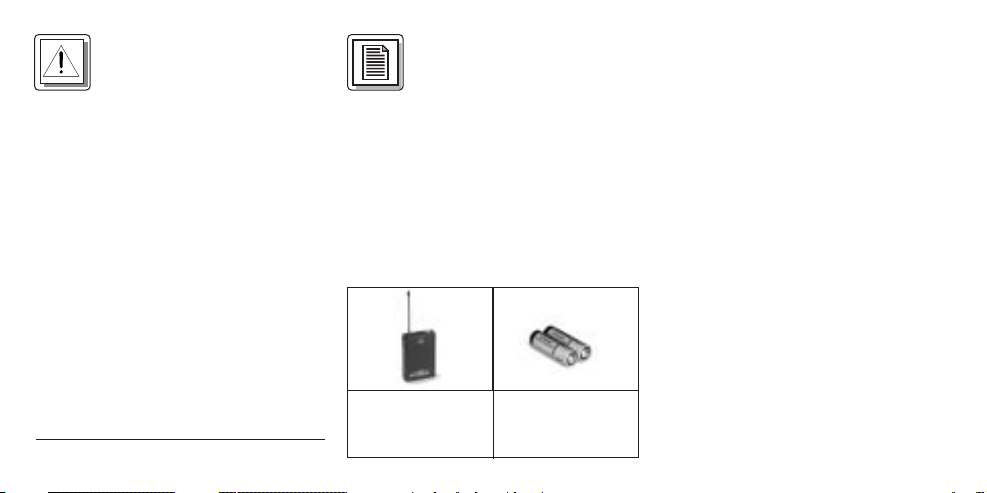
Kontrollieren Sie bitte, ob die Verpackung alle oben angeführten Teile enthält. Falls etwas fehlt, wenden Sie sich
bitte an Ihren AKG-Händler.
2.3 Empfohlenes Zubehör
Tasche CB 40
2.4 Beschreibung
An den Taschensender PT 40 können
Sie sowohl dynamische Mikrofone als
auch Kondensatormikrofone anschließen, die mit einer Versorgungsspannung von ca. 3,8 Volt arbeiten.
Selbstverständlich können Sie auch eine
E-Gitarre, einen E-Bass oder ein
Umhängekeyboard anschließen.
Der PT 40 arbeitet auf einer fixen, quarzstabilisierten Trägerfrequenz im UHFTrägerfrequenzbereich von 710 MHz bis
865 MHz.
2
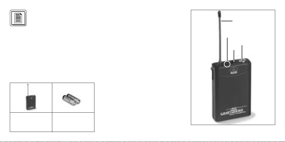
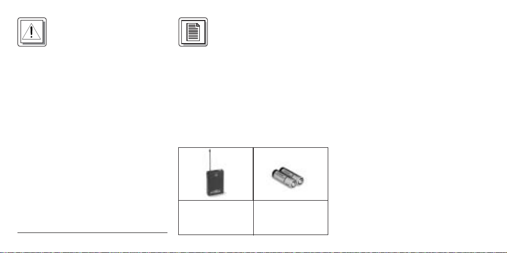
1 Taschensender
PT 40
2 Batterien 1,5 V,
Größe AA
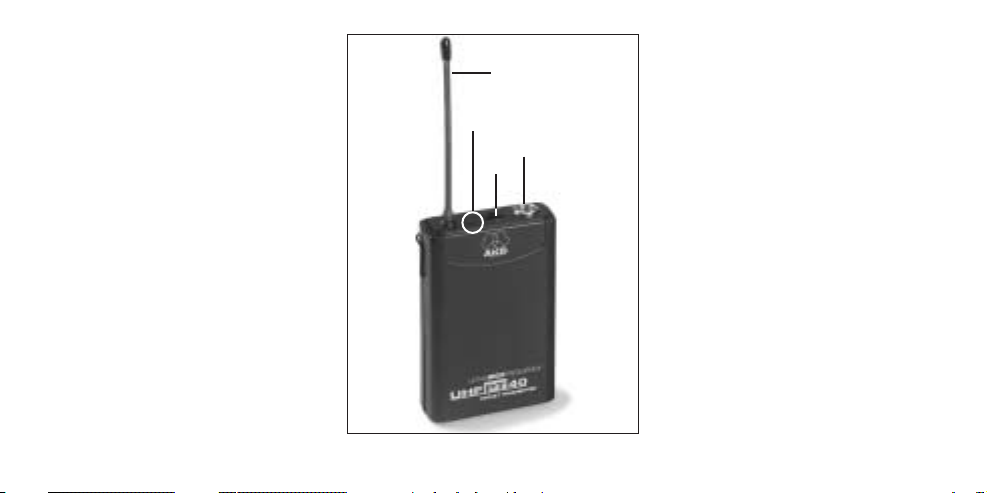
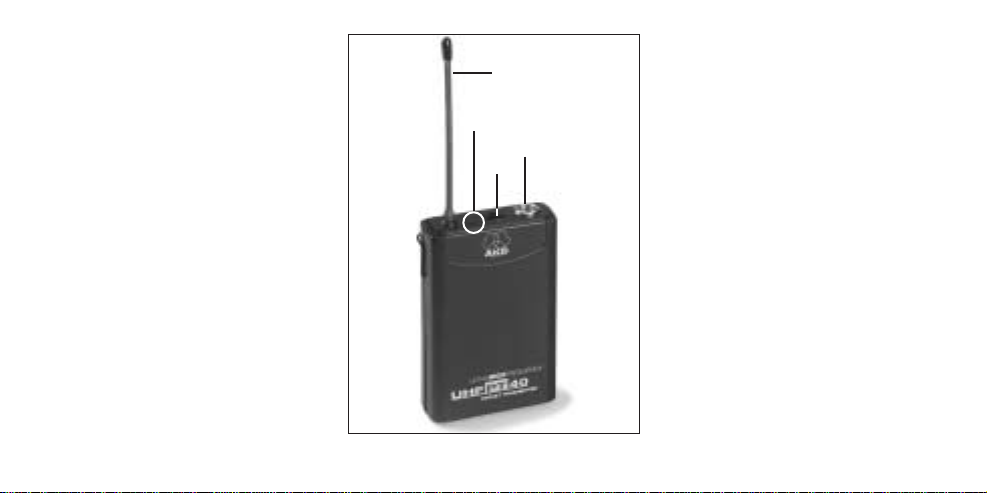
2.5 Bedienelemente an der
Oberseite (siehe Abb. 1)
1 Ein/Ausschalter: Dieser Schiebe-
schalter hat drei Stellungen:
ON: Die Spannungsversorgung für
den Sender ist eingeschaltet.
MUTE: Das vom Mikrofon bzw.
Instrument kommende Audiosignal ist stummgeschaltet,
Spannungsversorgung und HFTrägerfrequenz bleiben jedoch
eingeschaltet. Dadurch wird der
Empfänger trotz ”abgeschaltetem Mikrofon nicht durch andere
Sender gestört.
OFF: Die Spannungsversorgung für
den Sender ist ausgeschaltet.
2 Kontroll-LED: Diese LED zeigt den
Ladezustand der Batterien an.
LED leuchtet beim Einschalten kurz
auf und erlischt wieder: Batterien in
Ordnung.
LED leuchtet: Batterien in ca. 50
Minuten erschöpft.
3 Audioeingang: 3-polige Mini-XLR-
Buchse mit Kontakten für Mikrofonund Linepegel. Durch die Steckerbeschaltung der empfohlenen
AKG-Mikrofone bzw. des Gitarrenkabels MKG/L (nicht mitgeliefert)
werden automatisch die richtigen
Kontakte belegt.
4 Antenne: Fix montierte, flexible
Antenne.
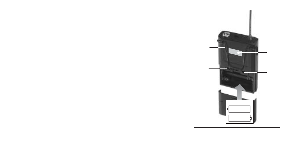
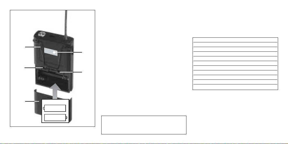
2.6 Bedienelemente an der
Rückseite (s. Abb. 2, S. 4)
5 Gürtelspange: Zum Befestigen
des Taschensenders am Gürtel.
6 Batteriefachdeckel: Siehe Ka-
pitel 3.2 Batterien einlegen.
7 MIC/LINE: Dieser Schiebeschalter
schaltet den Audioteil zwischen
3
Abb. 1: Oberseite
1
2
3
4

Mikrofonpegel (”MIC”) und Linepegel (”LINE”) um.
8 GAIN: Mit diesem Regler können
Sie die Empfindlichkeit des
Audioteils an den Pegel des angeschlossenen Mikrofons bzw.
Instruments anpassen.
9Trägerfrequenzetikette: An der
Rückseite des Senders ist eine
Haftetikette mit der Trägerfrequenz
des Senders, dem entsprechenden
Farbcode (Empfänger mit derselben Trägerfrequenz sind mit derselben Farbe gekennzeichnet) und den
Prüfzeichen angebracht.
2.7 Mikrofone, Gitarrenkabel (nicht
mitgeliefert)
Folgende AKG-Mikrofone können Sie
problemlos an den Audioeingang des
PT 40 anschließen:
Mittels des Gitarrenkabels MKG/L von
AKG können Sie eine E-Gitarre, einen EBass oder ein Umhängekeyboard anschließen.
2.8 Farbcode-Tabelle
4
7
5
6
8
9
2 x 1.5V
+–
+
–
Abb. 2: Rückseite
C 417 L
C 420 L
C 444 L
C 419 L
D 409 L
CK 55 L
C 411 L
C 418 L
LM 3 L
Frequenz Farbe
US54: 710.400 MHz rotbraun
US58: 734.600 MHz purpur
KR3: 745.650 MHz mintgrün
KR4: 750.900 MHz dunkelgrau
EU62: 802.525 MHz bordeauxrot
EU63: 812.800 MHz gelb
UK69A: 854.900 MHz violett
UK69B: 858.200 MHz grün
ISM1: 863.100 MHz melonengelb
ISM2: 864.375 MHz grau
3 Inbetriebnahme
3.1 Empfänger positionieren
Reflexionen des Sendersignals an
Metallteilen, Wänden, Decken, etc. oder
Abschattungen durch menschliche
Körper können das direkte Sendersignal
schwächen bzw. auslöschen.
Stellen Sie den Empfänger daher wie
folgt auf:
1. Positionieren Sie den Empfänger
immer in der Nähe des Aktionsbereiches (Bühne), achten Sie jedoch
auf einen Mindestabstand zwischen
Sender und Empfänger von 3 m bis
optimal 5 m.
2. Voraussetzung für optimalen
Empfang ist Sichtverbindung zwischen Sender und Empfänger.
3. Positionieren Sie den Empfänger in
einem Abstand von mehr als
1,5 m von großen metallenen Gegenstände, Wänden, Bühnengerüsten,
Decken, u.ä.
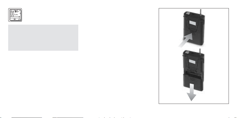
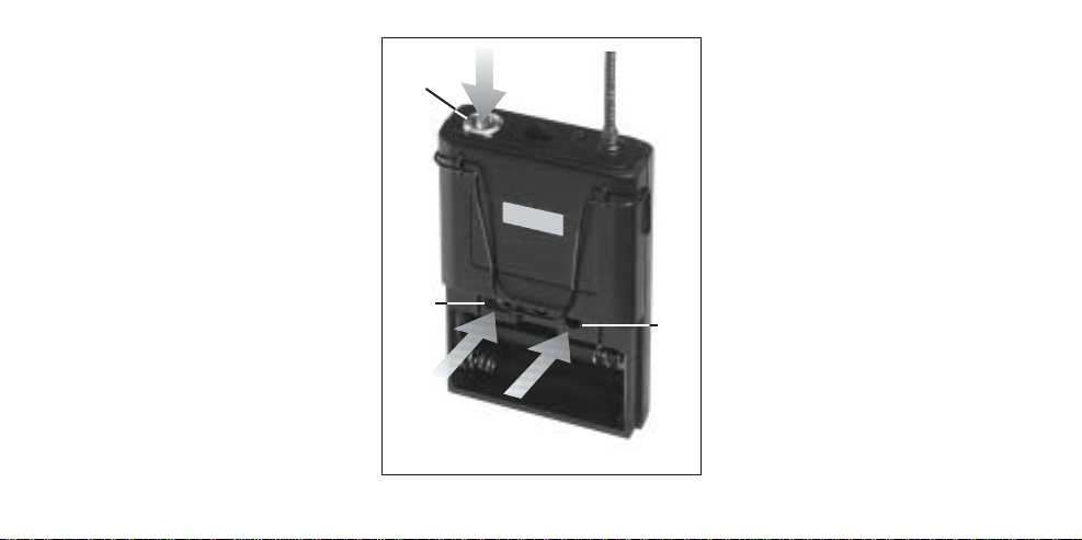
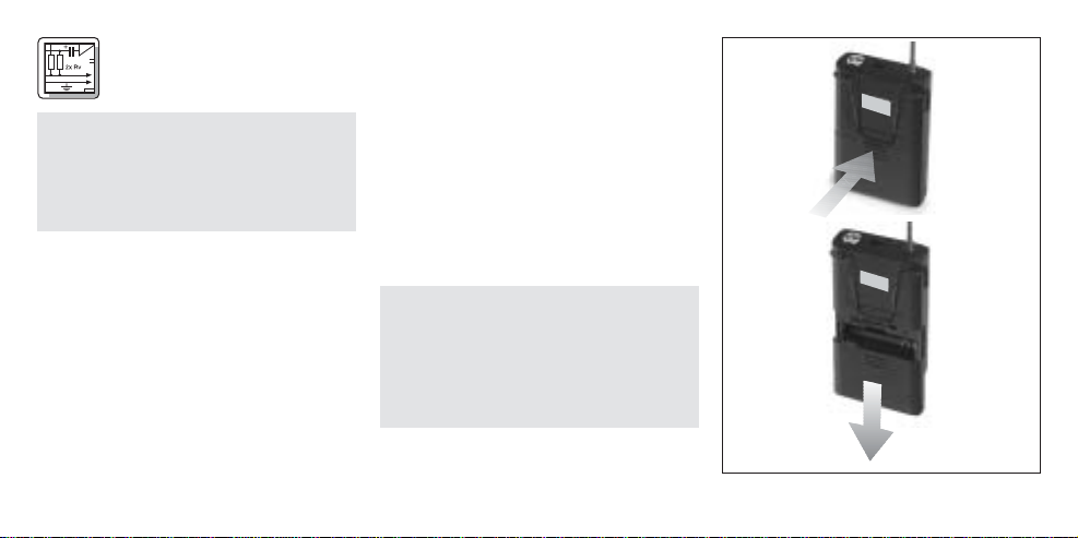
3.2 Batterien einlegen und testen
(siehe Abb. 1 bis 3)
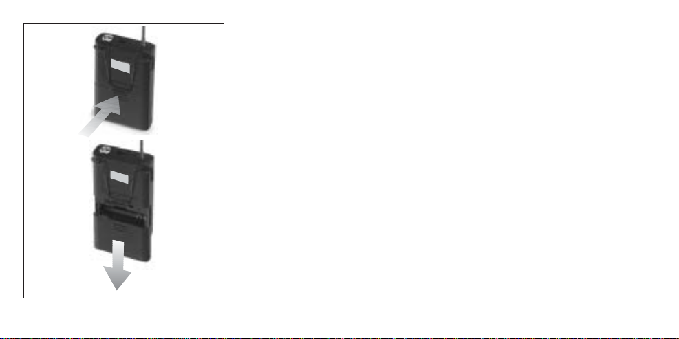
1. Drücken Sie den Schnapphaken am
Batteriefachdeckel (6) nach unten.
2. Ziehen Sie den Batteriefachdeckel (6)
nach unten vom Sender ab.
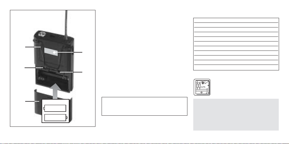
3. Legen Sie die mitgelieferten Batterien
in das Batteriefach ein und achten
Sie dabei auf die richtige Polarität der
Batterien.
5
Wichtig: Bevor Sie Ihr WMS 40 in
Betrieb nehmen, kontrollieren Sie, ob
Sender und Empfänger auf derselben
Frequenz arbeiten. Am leichtesten
können Sie dies anhand des
Farbcodes überprüfen.
Abb. 3: Batterien einlegen

Wenn Sie die Batterien falsch einlegen, wird der Sender nicht mit Strom
versorgt.
4. Schalten Sie den Sender ein, indem
Sie den Ein/Aus-Schalter (1) auf “ON”
stellen.
Die Kontroll-LED (2) blitzt kurz auf. Wenn
die Batterien in gutem Zustand sind,
erlischt die Kontroll-LED (2 )wieder.
Wenn die Kontroll-LED (2) zu leuchten beginnt, sind die Batterien in ca.
50 Minuten erschöpft. Tauschen Sie
die Batterien möglichst bald gegen
frische aus.
Wenn die Kontroll-LED (2) nicht aufblitzt, sind die Batterien erschöpft.
Legen Sie neue Batterien ein.
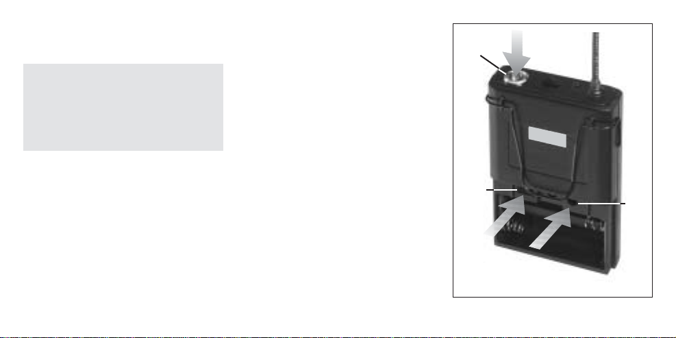
5. Schließen Sie das Batteriefach,
indem Sie den Batteriefachdeckel
von unten auf das Batteriefach aufschieben, bis der Schnapphaken einrastet.
3.3 Sender in Betrieb nehmen
3.3.1 Mikrofon anschließen
Der Taschensender PT 40 ist für die
Verwendung mit den ”L”-Mikrofonen
der MicroMic-Serie von AKG (siehe
Kapitel 2.7) ausgelegt. Wenn Sie andere
Mikrofone von AKG oder auch von anderen Herstellern an den PT 40 anschließen möchten, beachten Sie bitte,
dass Sie eventuell den Stecker Ihres
Mikrofons umlöten oder durch einen 3poligen Mini-XLR-Stecker ersetzen müssen.
Kontaktbelegung des Audioeingangs:
Kontakt 1: Abschirmung
Kontakt 2: Tonader (inphase)
Kontakt 3: Versorgungsspannung
An Kontakt 3 steht eine positive
Versorgungsspannung von 3,8 V für
Kondensatormikrofone zur Verfügung.
1. Nehmen Sie den Batteriefachdeckel ab.
2. Stellen Sie den MIC/LINE-Schalter (7)
auf ”MIC” und drehen Sie mit einem
kleinen Schraubenzieher den GAINRegler (8) bis zur Mitte zwischen dem
linken und rechten Anschlag auf.
6
Wichtig: Der Schaumstoffpolster an der
Innenseite des Batteriefachdeckels
fixiert die Batterien in ihrer Position.
Entfernen Sie den Schaumstoffpolster nicht, da die Batterien ansonsten nicht richtig im Batteriefach
fixiert sindund Klappergeräusche
verursachen können
Wichtig: Wir bitten Sie um Verständnis
dafür, dass AKG eine einwandfreie
Funktion des Taschensenders PT 40
mit Fremdfabrikaten nicht garantieren kann, und eventuelle Schäden
infolge des Betriebs mit Fremdfabrikaten von der Garantieleistung
ausgeschlossen sind.

3. Stecken Sie den Mini-XLR-Stecker am
Kabel Ihres Mikrofons an die AudioEingangsbuchse (3) des Taschensenders an.
4. Schalten Sie den Taschensender ein,
indem Sie den Ein/Aus-Schalter auf
”ON” stellen.
5. Schalten Sie den Empfänger und Ihre
PA-Anlage bzw. Ihren Verstärker ein.
Kontrollieren Sie die Stellung des
VOLUME-Reglers am Empfänger:
Empfänger mit Mikrofoneingang
verbunden = linker Anschlag,
Empfänger mit Line-Eingang ver-
bunden = rechter Anschlag.
6. Sprechen oder singen Sie in das
Mikrofon und stellen Sie die Lautstärke der PA-Anlage bzw. des
Verstärkers wie in deren Bedienungsanleitung beschrieben oder nach
Gehör ein. (Siehe auch Kapitel 4
Mikrofontechnik.)
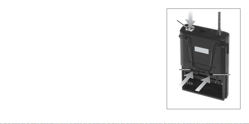
3.3.2 Instrument anschließen (s. Abb. 4)
1. Nehmen Sie den Batteriefachdeckel
ab.
2. Stellen Sie den MIC/LINE-Schalter (7)
auf ”LINE” und drehen Sie mit einem
kleinen Schraubenzieher den GAINRegler (8) bis zur Mitte zwischen dem
linken und rechten Anschlag auf.
3. Stecken Sie den Klinkenstecker des
Gitarrenkabels MKG/L (optional) an
die Ausgangsbuchse Ihres Instruments und den Mini-XLR-Stecker
des Gitarrenkabels an die AudioEingangsbuchse (3) des Taschensenders an.
4. Schalten Sie den Taschensender ein,
indem Sie den Ein/Aus-Schalter auf
”ON” stellen.
5. Schalten Sie den Empfänger und Ihre
PA-Anlage bzw. Ihren Verstärker ein.
Kontrollieren Sie die Stellung des
VOLUME-Reglers am Empfänger:
Empfänger mit Mikrofoneingang
7
3
7
8
Abb. 4: Instrument anschließen
verbunden = linker Anschlag,
Empfänger mit Line-Eingang ver-
bunden = rechter Anschlag.
6. Spielen Sie auf Ihrem Instrument und
stellen Sie die Lautstärke der PAAnlage bzw. des Verstärkers wie in
deren Bedienungsanleitung beschrieben oder nach Gehör ein.
3.4 Vor dem Soundcheck
1. Schreiten Sie den Bereich ab, in dem
Sie den Sender einsetzen werden.
Achten Sie dabei auf Stellen, wo die
Feldstärke absinkt und daher der
Empfang kurzzeitig gestört wird
(“Dropouts”).
Solche Dropouts können Sie beheben, indem Sie den Empfänger
anders positionieren. Hat dies keinen
Erfolg, vermeiden Sie diese kritischen
Stellen.
2. Wenn am Empfänger die die RF-LED
erlischt, bedeutet dies, dass kein
Signal empfangen wird oder der
Squelch aktiv ist.
Schalten Sie den Sender ein und/oder
gehen Sie näher zum Empfänger, bis
die RF-LED am Empfänger aufleuchtet.
4 Mikrofontechnik
4.1 Lavaliermikrofone
C 417 L, CK 55 L
1. Befestigen Sie das Mikrofon am
Ansteckclip H 40/1 oder an der
Anstecknadel H 41/1 wie in der
Bedienungsanleitung des Mikofons
beschrieben.
2. Klemmen Sie das Mikrofon so nahe
beim Mund wie möglich an der
Kleidung an.
Die Rückkopplungsgefahr ist umso
geringer, je näher das Mikrofon beim
Mund sitzt!
3. Achten Sie darauf, das Mikrofon auf
den Mund auszurichten.
4.2 Headset-Mikrofone C 420 L,
C 444 L
Anwendungshinweise für diese beiden
Headset-Mikrofone von AKG finden Sie
in der Bedienungsanleitung des jeweiligen Mikrofons.
4.3 Fehlerbehebung
Hinweise zur Fehlerbehebung finden
Sie in der Bedienungsanleitung Ihres
Empfängers.
5 Reinigung
Zum Reinigen der Oberflächen
des Senders verwenden Sie am
besten ein mit Wasser befeuchte-
tes weiches Tuch.
8

9
6 Technische Daten
Trägerfrequenz 710 - 865 MHz
Modulation FM
Audioübertragungsbandbreite 40 - 20.000 Hz
Frequenzstabilität (-10°C bis +50°C) ±15 kHz
Nennhub 15 kHz
Klirrfaktor bei 1 kHz typ. 0,8%
Kompander integriert
Signal/Rauschabstand typ. 103 dB(A)
HF-Ausgangsleistung 10 mW
Stromaufnahme typ. 70 mA
Spannungsversorgung 2 x 1,5 V-Batterien Größe AA
Betriebszeit typ. 30 h
Audio-Eingangspegel für Nennhub 300 mV (MIC); 110 mV (LINE)
Eingangsimpedanz typ. 140 kΩ//450 pF (LINE)
Speisung für Mikrofonkapsel 3,8 V/4,7 kΩ (Stift 3)
Abmessungen (B x T x H) 64 x 22 x 96 mm
Nettogewicht 76 g
Dieses Produkt entspricht den Normen EN60065:1998,
EN301 489-9 v.1.1.1 (09-2000) und EN300 422-2 v.1.1.1 (07-2000).

FCC Statement
This equipment has been tested and
found to comply with the limits for a Class
B digital device, pursuant to Parts 74, 15,
and 90 of the FCC Rules. These limits are
designed to provide reasonable protection against harmful interference in a residential installation. This equipment generates, uses, and can radiate radio frequency energy and, if not installed and
used in accordance with the instructions,
may cause harmful interference to radio
communications. However, there is no
guarantee that interference will not occur
in a particular installation. If this equipment does cause harmful interference to
radio or television reception, which can
be determined by turning the equipment
off and on, the user is encouraged to try
to correct the interference by one or more
of the following measures:
• Reorient or relocate the receiving
antenna.
• Increase the separation between the
equipment and the receiver.
• Connect the equipment into an outlet
on a circuit different from that to
which the receiver is connected.
• Consult the dealer or an experienced
radio/TV technician for help.
Shielded cables and I/O cords must be
used for this equipment to comply with
the relevant FCC regulations.
Changes or modifications not expressly
approved in writing by AKG Acoustics
may void the user’s authority to operate
this equipment.
This device complies with Part 15 of the
FCC Rules. Operation is subject to the
following two conditions: (1) this device
may not cause harmful interference, and
(2) this device must accept any interference received, including interference
that may cause undesired operation.
1 Safety and
Environment
1.1 Safety
1. Do not expose the equipment to
direct sunlight, excessive dust, moisture, rain, mechanical vibrations, or
shock.
1.2 Environment
1. Be sure to dispose of used batteries
as required by local waste disposal
rules. Never throw batteries into a fire
(risk of explosion) or garbage bin.
2. When scrapping the equipment,
remove the batteries, separate the
case, circuit boards, and cables, and
dispose of all components in accordance with local waste disposal rules.
10
2 Description
2.1 Introduction
Dear Customer:
Thank you for purchasing an AKG
product. Please take a few minutes to
read the instructions below carefully
before operating the equipment.
Please keep the Manual for future reference. Have fun and impress your
audience!
2.2 Unpacking
Check that the package contains all the
parts listed above. If anything is missing,
please contact your AKG dealer.
2.3 Optional Accessories
CB 40 bag
2.4 Description
You can use the PT 40 bodypack transmitter with both dynamic microphones
and condenser microphones operating
on a supply voltage of approx. 3.8 V. You
may also connect an electric guitar, electric bass, or remote keyboard.
The PT 40 operates on one fixed, quartz
stabilized frequency in the 710 MHz to
865 MHz UHF carrier frequency range.
2.5 Top Panel Controls (Refer to fig. 1)
1On/Off Switch: This slide switch
provides three positions labeled as
follows:
11
Fig. 1: Top panel controls
1
2
3
4
1 PT 40 bodypack
transmitter
2 AA size dry
batteries
ON: Power to the transmitter is on.
MUTE: The signal delivered by the
microphone or instrument is
muted while power and the RF
carrier frequency remain on. This
prevents the receiver from responding to interference from
other transmitters.
OFF: Power to the transmitter is off.
2 Status LED: Indicates battery status.
LED flashes momentarily upon
switching ON and extinguishes:
batteries are OK.
LED lights constantly: batteries will
be dead in about 50 minutes.
3 Audio input: 3-pin mini XLR
connector with both mic and line
level pins that automatically match
the connector pinout of the recommended AKG microphones or
optional MKG/L guitar cable.
4Antenna: Permanently connected,
flexible antenna.
2.6 Rear Panel Controls (Refer to fig. 2)
5 Belt Clip for fixing the transmitter
to your belt.
6 Battery Compartment Lid: Refer
to section 3.2 Inserting Batteries.
7 MIC/LINE: This slide switch sets
the audio input either to microphone level (“MIC” position) or line level
(“LINE” position).
8 GAIN: This rotary pot matches the
sensitivity of the transmitter’s audio
section to the level of the connected microphone or instrument.
9 Carrier Frequency Label: The
label on the transmitter rear panel
indicates the carrier frequency,
color code (receivers with the same
carrier frequency are marked with
the same color), and approval
marks of your transmitter.
12
7
5
6
8
9
2 x 1.5V
+–
+
–
Fig. 2: Rear panel controls
2.7 Microphones, Guitar Cable
(optional)
You can connect the following micro-
phones to the audio input of the PT 40:
The MKG/L guitar cable from AKG lets
you connect an electric guitar, electric
bass, or remote keyboard to the bodypack transmitter.
2.7 Color Code Table
3 Setting Up
3.1 Placing the Receiver
Reflections off metal parts, walls, ceilings, etc. or the shadow effects of musicians and other people may weaken or
cancel the direct transmitter signal.
For best results, place the receiver as
follows:
1. Place the receiver near the performance area (stage). Make sure, though,
that the transmitter will never get any
closer to the receiver than 10 ft (3 m).
Optimum separation is 16 ft. (5 m).
2. Check that you can see the receiver
from where you will be using the
transmitter.
3. Place the receiver at least 5 ft. (1.5 m)
away from any big metal objects,
walls, scaffolding, ceilings, etc.
3.2 Inserting and Testing Batteries
(Refer to figs. 1 to 3)
1. Depress the snap hook on the battery
compartment lid (6).
13
Frequency Color
US54: 710.400 MHz reddish brown
US58: 734.600 MHz purple
KR3: 745.650 MHz mint green
KR4: 750.900 MHz dark gray
EU62: 802.525 MHz Bordeaux red
EU63: 812.800 MHz yellow
UK69A: 854.900 MHz violet
Frequency Color
UK69B: 858.200 MHz green
ISM1: 863.100 MHz melon yellow
ISM2: 864.375 MHz gray
Important: Prior to setting up your
WMS 40, check that the transmitter
and receiver are tuned to the same
frequency. The easiest way to do this
is to compare the color codes on the
transmitter and receiver.
Important: The foam pads on the inside
of the battery compartment lid holds
the batteries in place. Do not remove
the foam pad. If you do, the batteries
will not be held in place properly and
may cause a rattling noise.
C 417 L
C 420 L
C 444 L
C 419 L
D 409 L
CK 55 L
C 411 L
C 418 L
LM 3 L
2. Pull the battery compartment lid (6)
down to remove it from the transmitter.
3. Insert the supplied batteries into the
battery compartment conforming to
the polarity marks.
The transmitter will not function with
incorrectly inserted batteries.
4. Set the on/off switch (1) to “ON” to
switch the power to the transmitter on.
The status LED (2) will flash momentarily. If the batteries are in good condition, the status LED (2) will extinguish.
If the status LED (2) illuminates the
batteries will be dead within about 50
minutes. Replace the batteries with
new ones as soon as possible.
If the status LED (2) fails to flash
momentarily the batteries are dead.
Insert new batteries.
5. To close the battery compartment,
slide the battery compartment
lid (6) onto the battery compartment
from below to the point that it will
click shut.
3.3 Setting Up the Transmitter
3.3.1 Connecting a Microphone
The PT 40 bodypack transmitter has
been designed primarily for use with ”L”
type MicroMic Series microphones from
AKG (see section 2.7). If you wish to
connect other microphones from AKG or
other manufacturers to the PT 40, please note that you may have to rewire the
existing connector of your microphone
or replace it with a 3-pin mini XLR
connector.
Audio input pinout:
Pin 1: shield
Pin 2: audio (inphase)
Pin 3: supply voltage
14
Fig. 3: Inserting batteries
A positive supply voltage of 3.8 V for
condenser microphones is available on
pin 3.
1. Remove the battery compartment lid.
2. Set the MIC/LINE switch (7) to “MIC”
and use a small screwdriver to set the
GAIN control (8) to a position halfway
between full CCW and full CW.
3. Plug the mini XLR connector on the
cable of your microphone into the
audio input connector (3) on the
bodypack transmitter.
4. Set the on/off switch (1) to “ON” to
switch power to the transmitter on.
5. Switch power to the receiver and
your sound system or amplifier on.
Check the setting of the VOLUME
control on the receiver:
Fully CCW if you connected the
receiver to a microphone input.
Fully CW if you connected the
receiver to a line input.
6. Talk or sing into the microphone and
set the levels on your mixer or amplifier referring to the appropriate
instruction manual or by ear.
3.3.2 Connecting an Instrument (fig. 4)
1. Remove the battery compartment lid.
2. Set the MIC/LINE switch (7) to “LINE”
and use a small screwdriver to set the
GAIN control (8) to a position halfway
between full CCW and full CW.
3. Plug the 1/4” jack plug on the optional MKG/L guitar cable to the output
jack on your instrument and the mini
XLR connector on the guitar cable
15
Important: Please note that AKG cannot
guarantee that the PT 40 bodypack
transmitter will work perfectly with
products from other manufacturers
and any damage that may result from
such use is not covered by the AKG
warranty scheme.
3
7
8
Fig. 4: Connecting an instrument
into the audio input connector (3) on
the bodypack transmitter.
4. Set the on/off switch (1) to “ON” to
switch power to the transmitter on.
5. Switch power to the receiver and
your sound system or amplifier on.
Check the setting of the VOLUME
control on the receiver:
Fully CCW if you connected the
receiver to a microphone input.
Fully CW if you connected the
receiver to a line input.
6. Play your instrument and set the
levels on your mixer or amplifier referring to the appropriate instruction
manual or by ear.
3.4 Before the Soundcheck
1. Move the transmitter around the area
where you will use the system to
check the area for "dead spots", i.e.,
places where the field strength seems
to drop and reception deteriorates.
If you find any dead spots, try to eliminate them by repositioning the
receiver. If this does not help, avoid
the dead spots.
2. The RF LED on the receiver going out
means no signal is being received or
the squelch is active.
Switch power to the transmitter ON
and/or move closer to the receiver, to
the point that the RF LED on the
receiver will come back on.
4 Microphone
Technique
4.1 C 417 L, CK 55 L
Lavalier Microphones
1. Fix the microphone to the H 40/1 lavalier clip or H 41/1 tie pin referring to the
microphone’s instruction manual.
2. Clamp the microphone on your clothing as close as possible to your
mouth.
Remember that gain-before-feedback will be the higher the smaller the
distance between the microphone
and the mouth!
3. Make sure to aim the microphone at
your mouth.
4.2 C 420 L, C 444 L Head-worn
Microphones
Refer to the user’s manual of the respective microphone for instructions on how
to use head-worn microphones.
4.3 Troubleshooting
For troubleshooting hints, refer to the
instruction manual of your receiver.
5 Cleaning
To clean the transmitter case,
use a soft cloth moistened with
water.
16

17
6 Specifications
Carrier frequency range 710 to 865 MHz
Modulation FM
Audio bandwidth 40 to 20,000 Hz
Frequency stability (-10°C to +50°C) ±15 kHz
Rated deviation 15 kHz (SP1, SP2: 13.5 kHz)
T.H.D. at 1 kHz 0.8% typ.
Compander integrated
Signal/noise ratio 103 dB(A) typ.
RF output 10 mW
Current consumption 70 mA typ.
Power requirement two 1.5-V AA size batteries
Battery life 30 hours typ.
Audio input level for rated deviation 300 mV (MIC); 110 mV (LINE)
Input impedance typ. 140 kΩ//450 pF (LINE)
Condenser mic power supply 3.8 V/4.7 kΩ (pin 3)
Size (WxDxH) 64 x 22 x 96 mm / (2.5 x 0.9 x 3.8 in.)
Net weight 76 g (2.7 oz.)
This product complies with the following standards:
EN60065:1998, EN301 489-9 v.1.1.1 (09-2000), and EN300 422-2 v.1.1.1 (07-2000).

1 Sécurité et
écologie
1.1. Sécurité
1. Ne placez jamais l’appareil à un
endroit où il risque d’être exposé
directement au soleil, à une atmosphère poussiéreuse, à l’humidité, à la
pluie, aux vibrations ou aux secousses.
1.2. Ecologie
1. Conformez-vous aux règlements en
vigueur pour la mise au rebut des
piles usées. Ne mettez jamais des
piles ni au feu (risque d’explosion) ni
aux ordures ménagères.
2. Si vous mettez l'appareil à la ferraille,
enlevez les piles ou les accus, séparez le boîtier, l'électronique et les
câbles et éliminez les différents éléments conformément aux règlements
en vigueur.
2 Description
2.1 Introduction
Nous vous remercions d’avoir
choisi un produit AKG.
Lisez très attentivement ce mode d’emploi avant la mise en service de l’ap-
pareil. Conservez soigneusement le
mode d’emploi pour pouvoir le consulter
lorsque vous vous posez des questions.
Nous vous souhaitons beaucoup de
succès.
2.2. Equipement fourni
Contrôlez si le carton contient bien tous
les éléments énumérés ci-dessus. Si ce
n’est pas le cas, veuillez contacter votre
distributeur AKG.
2.3 Accessoires optionnels
Pochette CB 40
2.4 Description
L’émetteur de poche PT 40 peut être utilisé aussi bien avec des microphones
dynamiques qu’avec des microphones
électrostatiques fonctionnant sur une
tension d’alimentation de 3,8 volts environ. Vous avez bien sûr aussi la possibilité de raccorder une guitare, une basse
ou un clavier portatif.
Le PT 40 fonctionne sur une fréquence
porteuse fixe, stabilisée par cristal, dans
la gamme UHF de 710 MHz à 865 MHz.
18
1 émetteur de
poche PT 40
2 piles de 1,5 V,
dimension AA

2.5 Eléments de commande en
haut de boîtier
(Cf. Fig. 1)
1 Interrupteur marche/arrêt : Ce
curseur a trois positions :
ON : L’émetteur est sous tension.
MUTE : Le signal audio venant du
microphone ou de l’instrument
est sur muet mais l’alimentation
et la fréquence porteuse HF sont
maintenues. Bien que le microphone soit coupé, le récepteur
n’est pas perturbé par d’autres
émetteurs.
OFF : L’alimentation de l’émetteur
est coupée.
2 Témoin LED : cette LED indique
l’état des piles.
La LED s’allume et s’éteint aussitôt
: les piles sont chargées.
La LED reste allumée : les piles ont
encore environ 50 minutes d’autonomie.
3 Entrée audio : Prise tripôlaire mini
XLR avec contacts pour niveaux
micro et ligne. Le brochage de la
prise du micro ou du câble de guitare MKG/L (ne fait pas partie des
fournitures) assure automatiquement le raccordement aux bornes
voulues.
4 Antenne : Antenne souple, montée
à demeure.
2.6 Eléments de commande au dos
de l’émetteur (Cf. Fig. 2, p. 20)
5 Agrafe de ceinture : pour fixer l’é-
metteur de poche à la ceinture
6 Couvercle du compartiment
des piles : Voir point 3.2 Mise en
place des piles
7 MIC/LINE : Ce curseur permet de
commuter la section audio entre
niveau micro (“MIC”) et niveau ligne
(“LINE”).
8 GAIN : Ce régulateur permet d’ad-
apter la sensibilité de la section
19
Fig. 1 : Eléments de commande (en haut)
1
2
3
4
audio au niveau du microphone ou
de l’instrument raccordé.
9 Etiquette fréquences porteuses :
une étiquette collée au dos de l’émetteur indique la fréquence porteuse de l’émetteur, le code couleur
correspondant (les récepteurs fonctionnant sur la même fréquence
porteuse ont le même code couleur)
et les marques de conformité.
2.7 Microphones, câble guitare (ne
font pas partie des fournitures)
Vous pouvez brancher sans problème
les microphones AKG suivants sur l’entrée audio du PT 40:
Vous pouvez également brancher une
guitare, une basse ou un clavier portatif
à l’aide du câble guitare MKG/L d’AKG.
2.8 Tableau des codes couleur
3 Mise en service
20
7
5
6
8
9
2 x 1.5V
+–
+
–
Fig. 2 : Eléments de commande (dos)
Fréquence Couleur
US54: 710.400 MHz brun rouge
US58: 734.600 MHz pourpre
KR3: 745.650 MHz menthe
KR4: 750.900 MHz gris foncé
EU62: 802.525 MHz bordeaux
EU63: 812.800 MHz jaune
UK69A: 854.900 MHz violet
UK69B: 858.200 MHz vert
ISM1: 863.100 MHz jaune melon
ISM2: 864.375 MHz gris
Important: Vérifiez si l’émetteur et
récepteur fonctionnent sur la même
fréquence porteuse avant de mettre
en service votre système WMS 40.
L’émetteur et le récepteur doivent
avoir le même code couleur.
C 417 L
C 420 L
C 444 L
C 419 L
D 409 L
CK 55 L
C 411 L
C 418 L
LM 3 L

3.1 Lieu d’installation
Les réflexions du signal de l’émetteur
sur les surfaces métalliques, les murs, le
plafond, etc. de même que l’écran du
corps humain risquent d’affaiblir voire
supprimer le signal direct de l’émetteur.
Veillez donc aux points suivants:
1. Placez toujours le récepteur à proximité du lieu d’action (scène) en respectant toutefois une distance minimum de 3 m à 5 m (distance optimale) entre émetteur et récepteur.
2. Le contact visuel entre les points
d’installation de l’émetteur et du
récepteur est une condition indispensable pour avoir une réception
optimale.
3. Placez le récepteur à plus de 1,5 m
des objets métalliques volumineux,
des murs, des décors, du plafond,
etc.
3.2 Mise en place et essai des piles
(Voir Fig. 1 à 3)
1. Poussez le fermoir à déclic du couvercle du compartiment des piles (6)
vers le bas.
2. Tirez le couvercle (6) par le bas.
3. Placez les piles fournies avec l’émetteur dans le compartiment des piles
en veillant à ne pas intervertir les
pôles.
Si les piles ne sont pas mises correctement l’émetteur ne sera pas alimenté.
4. Mettez l’émetteur sous tension en
poussant l’interrupteur marche/arrêt (1)
sur “ON”.
21
Fig. 3 : Mise en place des piles
Important: Le coussinet de mousse à
l’intérieur du couvercle maintient les
piles en position. N’enlevez donc
jamais ce coussinet; les piles ne
seraient pas imobilisées et risqueraient de taper contre le boîtier.

Le voyant LED (2) lance un seul éclair
lorsque les piles sont en bon état.
Lorsque le voyant LED (2) se met à
briller, il reste encore environ 50
minutes d’autonomie. Remplacez
alors les piles dès que possible par
des piles fraîches.
Si le voyant LED (2) n’est pas allumé,
les piles sont épuisées. Mettez des
piles neuves.
5. Fermez le compartiment des piles en
faisant glisser le couvercle (6), introduit
par le bas, jusqu’au déclic du fermoir.
3.3 Pour mettre l’émetteur en service
3.3.1 Pour raccorder un microphone
L’émetteur de poche PT 40 est conçu
pour être utilisé avec les microphones
type ”L” de la série MicroMic de chez
AKG (voir chapitre 2.7). Si vous souhaitez raccorder au PT 40 d’autres microphones d’AKG ou d’autres marques, il
vous faudra éventuellement modifier la
configuration de la fiche ou la remplacer
par une fiche XLR tripolaire miniature.
Broches de l’entrée audio
Broche 1 : blindage
Broche 2 : point chaud
Broche 3 : tension d'alimentation
On dispose à la broche 3 d’une tension
d’alimentation positive de 3,8 V pour les
microphones électrostatiques.
1. Enlevez le couvercle du compartiment des piles.
2. Mettez le curseur MIC/LINE (7) sur
“MIC” et tournez le régulateur de
GAIN (8), à l’aide d’un petit tournevis,
pour l’amener à égale distance de la
butée droite et de la butée gauche.
3. Connectez la fiche XLR miniature du
câble de votre microphone sur la
prise d’entrée (3) de l’émetteur de
poche.
4. Mettez l’émetteur de poche sous tension en faisant occuper à l’interrupteur
marche/arrêt (1) la position “ON”.
5. Mettez le récepteur et votre sono ou
votre ampli sous tension.
Contrôlez la position du bouton de
réglage de VOLUME sur le récepteur :
Récepteur raccordé à une entrée
micro = bouton tourné à fond à
gauche ; récepteur raccordé à une
entrée ligne = bouton tourné à
fond à droite.
22
Important : Nous attirons votre attention
sur le fait qu’AKG ne peut garantir un
fonctionnement parfait de l’émetteur
de poche PT 40 avec des microphones ou câbles d’autres marques et
que d’éventuels dégâts provoqués
par l’utilisation avec des microphones d’autres marques ne sont pas
couverts par la garantie.
6. Parlez ou chantez devant le micro et
réglez le volume de la sono ou de
l’ampli comme indiqué dans leur
mode d’emploi ou à l’oreille.
3.3.2 Pour raccorder un instrument
(Cf. Fig. 4)
1. Enlevez le couvercle du compartiment des piles.
2. Mettez le curseur MIC/LINE (7) sur
“LINE” et tournez le régulateur de
GAIN (8), à l’aide d’u petit tournevis,
pour l’amener à égale distance de la
butée droite et de la butée gauche.
3. Connectez le jack du câble guitare
MKG/L (optionnel) sur la prise de sortie de votre instrument et la fiche XLR
miniature du câble guitare sur la prise
d’entrée audio (3) de l’émetteur de
poche.
4. Mettez l’émetteur de poche sous tension en faisant occuper à l’interrupteur marche/arrêt la position “ON”.
5. Mettez le récepteur et votre sono ou
votre ampli sous tension.
Contrôlez la position du bouton de
réglage de VOLUME sur le récepteur :
Récepteur raccordé à une entrée
micro = bouton tourné à fond à
gauche ; récepteur raccordé à une
entrée ligne = bouton tourné à
fond à droite.
6. Jouez sur votre instrument et réglez
le volume de la sono ou de l’ampli
comme indiqué dans leur mode
d’emploi ou à l’oreille.
3.4 Avant d’essayer le son
1. Parcourez la zone dans laquelle vous
utiliserez l’émetteur pour trouver les
points où l’intensité de champ est
insuffisante pour une bonne réception (décrochages).
Vous pouvez éviter les décrochages
en plaçant le récepteur à un autre
23
3
7
8
Fig. 4 : Raccorder un instrument
endroit. Si ceci ne donne pas de
résultats, évitez ces points critiques.
2. L’extinction de la LED RF du récepteur
signifie qu’aucun signal n’arrive au
récepteur ou que le squelch est actif.
Mettez l’émetteur sous tension et/ou
rapprochez-vous du récepteur jusqu’à ce que le témoin RF du récepteur s’allume.
4 Technique du micro
4.1 Microphones Lavalière
C 417 L, CK 55 L
1. Fixez le microphone au clip H 40/1 ou
à l’épingle H 41/1 comme indiqué dans
le mode d’emploi du microphone.
2. Agrafez le micro aux vêtements, aussi
près de la bouche que possible.
Il y aura d’autant moins de risque de
larsen que le micro sera plus près des
lèvres.
3. Veillez à ce que le micro soit bien ori-
enté vers la bouche de l’utilisateur.
4.2 Micros serre-tête C 420 L,
C 444 L
Vous trouverez les instructions d’utilisation de ces deux microphones AKG
dans leurs modes d’emploi respectifs.
4.3 Dépannage
Vous trouverez les instructions relatives
au dépannage dans le mode d’emploi de
votre récepteur.
5 Nettoyage
Le boîtier de l’émetteur se nettoie avec un chiffon humecté
d’eau.
24

25
6 Caractéristiques techniques
Fréquence porteuse 710 - 865 MHz
Modulation FM
Bande passante audio 40 - 20.000 Hz
Stabilité de fréquence (entre -10°C et +50°C) ±15 kHz
Excursion nominale 15 kHz (SP1, SP2 : 13,5 kHz)
Distorsion typ. (par harmonique) pour 1 kHz typ. 0,8%
Compresseur-expanseur intégré
Rapport signal sur bruit typ. typ. 103 dB (A)
Puissance sortie HF typ. 5 mW
Consommation typ. typ. 70 mA
Alimentation 2 piles de 1,5 V type AA
Autonomie > typ. 30 h
Niveau d’entrée audio pour l’excursion nominale 300 mV (MIC); 110 mV (LINE)
Impédance d’entrée typ. 140 kΩ//450 pF (LINE)
Alimentation capsule micro 3,8 V/4,7 kΩ (broche 3)
Dimensions (l x p x h) 64 x 22 x 96 mm
Poids net 76 g
Ce produit est conforme aux normes EN60065:1998, EN301 489-9 v.1.1.1 (09-2000)
et EN300 422-2 v.1.1.1 (07-2000).

1 Sicurezza ed
ambiente
1.1 Sicurezza
1. Non esponete l’apparecchio diretta-
mente al sole, alla polvere e all'umidità,
alla pioggia, a vibrazioni o a colpi.
1.2 Ambiente
1. Smaltite le batterie usate e gli accu-
mulatori usati sempre conformemente alle norme di smaltimento rispettivamente vigenti. Non gettate le batterie o gli accumulatori nel fuoco
(pericolo di esplosione) o nei rifiuti
residui.
2. Se rottamate l’apparecchio, togliete
le batterie risp. gli accumulatori,
separate scatola, elettronica e cavi e
smaltite tutti i componenti conformemente alle norme di smaltimento
vigenti per essi.
2 Descrizione
2.1 Introduzione
Vi ringraziamo di aver scelto un
prodotto dell‘AKG. Leggete per favore
attentamente le istruzioni per l’uso
prima di usare l’apparecchio e conservate le istruzioni per l’uso per poterle
consultare in caso di necessità. Vi auguriamo buon divertimento e molto successo!
2.2. In dotazione
Controllate per favore se la confezione
contiene tutti i componenti di cui sopra.
Se manca qualcosa rivolgetevi al vostro
rivenditore AKG.
2.3 Accessori raccomandati
Borsa CB 40
2.4 Descrizione
Al trasmettitore da tasca PT 40 potete
collegare sia microfoni dinamici che
microfoni a condensatore operanti con
una tensione di alimentazione di 3,8 V
circa. Naturalmente potete collegare
anche una chitarra elettrica, un basso
elettrico o un keyboard a tracolla.
Il PT 40 opera su una frequenza portante fissa, stabilizzata al quarzo, nella
gamma delle frequenze portanti UHF da
710 MHz fino a 865 MHz.
26
1 trasmettitore da
tasca PT 40
2 batterie da 1,5 V,
dimensione AA
2.5 Elementi di comando sul lato
superiore (vedi fig. 1)
1 Interruttore on/off: questo inter-
ruttore a scorrimento ha tre
posizioni:
ON: l’alimentazione per il trasmetti-
tore è inserita.
MUTE: il segnale audio provenien-
te dal microfono o dallo strumento è silenziato, l’alimentazione e la frequenza portante RF
rimangono comunque inserite.
In questo modo, il ricevitore non
viene disturbato da altri trasmettitori anche quando il microfono
è disinserito.
OFF: l’alimentazione per il trasmet-
titore è disinserita.
2 LED di controllo: questo LED indica
lo stato di carica delle batterie.
Al momento dell’inserimento, il LED
si accende brevemente e poi si
spegne: batterie a posto.
Il LED si accende e rimane acceso:
le batterie saranno esauste tra 50
minuti circa.
3 Ingresso audio: Presa mini-XLR a
tre poli con contatti per il livello
microfonico ed il livello Line. Grazie
al cablaggio dei connettori del
microfono rispettivamente del cavo
per chitarra MKG/L (non in dotazione) vengono occupati automaticamente i contatti giusti.
4Antenna: Antenna flessibile, mon-
tata in modo fisso.
2.6 Elementi di comando sul lato
posteriore (vedi fig. 2, p. 28)
5 Clip da cintura: per fissare il tras-
mettitore da tasca sulla cintura.
6 Coperchio comparto batterie: v.
capitolo 3.2 Come inserire le batterie.
7 MIC/LINE: questo interruttore a
scorrimento commuta la sezione
audio tra il livello microfonico
(“MIC”) e il livello Line (“LINE”).
27
Fig. 1: Lato superiore
1
2
3
4

8 GAIN: con questo regolatore pote-
te adattare la sensibilità della sezione audio al livello del microfono o
dello strumento collegato.
9 Etichetta frequenze portanti:
sul lato posteriore del trasmettitore
è disposta un’etichetta adesiva
recante l’indicazione della frequenza portante del trasmettitore, il corrispondente codice a colori (i ricevitori della stessa frequenza portante
sono contrassegnati con lo stesso
colore) e i contrassegni di controllo.
2.7 Microfoni, cavo per chitarra
(non in dotazione)
I seguenti microfoni AKG possono venir
collegati senza problemi all'ingresso
audio del PT 40:
Con il cavo per chitarra MKG/L della
AKG potete collegare una chitarra
elettrica, un basso elettrico oppure un
keyboard a tracolla.
2.8 Tabella codice a colori
28
Frequenza Colore
US54: 710.400 MHz rosso-marrone
US58: 734.600 MHz porpora
KR3: 745.650 MHz verde menta
KR4: 750.900 MHz grigio scuro
EU62: 802.525 MHz rosso bordeaux
EU63: 812.800 MHz giallo
UK69A: 854.900 MHz viola
UK69B: 858.200 MHz verde
ISM1: 863.100 MHz giallo melone
ISM2: 864.375 MHz grigio
7
5
6
8
9
2 x 1.5V
+–
+
–
Fig. 2: Lato posteriore
C 417 L
C 420 L
C 444 L
C 419 L
D 409 L
CK 55 L
C 411 L
C 418 L
LM 3 L

3 Messa in funzione
3.1 Posizionamento del ricevitore
Le riflessioni del segnale su parti metalliche, pareti, soffitti ecc. oppure le ombre
prodotte dall'interposizione del corpo
umano possono indebolire rispettivamente spegnere il segnale diretto del
trasmettitore.
Posizionate quindi il ricevitore come segue:
1. Posizionate il ricevitore sempre nelle
vicinanze del luogo d'impiego
(palco), facendo attenzione a mante-
nere una distanza minima tra trasmettitore e ricevitore di 3 m fino a 5 m
(distanza ottimale).
2. Presupposto per una ricezione ottimale è il collegamento a vista tra
trasmettitore e ricevitore.
3. Posizionate il ricevitore ad una
distanza di più di 1,5 m da grandi
oggetti metallici, pareti, impalcature,
soffitti e simili.
3.2 Come inserire e testare le bat-
terie (vedi figg. 1 a 3)
1. Premete il gancio ad innesto disposto
sul coperchio comparto batterie
verso il basso.
2. Sfilate il coperchio comparto batterie
dal trasmettitore tirandolo verso il
basso.
3. Inserite le batterie in dotazione nel
comparto batterie facendo attenzione alla corretta polarità delle batterie.
29
Importante: Prima di mettere il WMS 40
in esercizio, controllate se il trasmettitore e il ricevitore operino sulla stessa frequenza portante. Il ricevitore ed
il trasmettitore devono portare lo
stesso codice a colore.
Fig. 3: Come inserire le batterie

Se inserite le batterie in modo sbagliato, il trasmettitore non viene alimentato con corrente.
4. Attivate il trasmettitore portando il
selettore on/off (1) in posizione "ON".
Il LED di controllo (2) si accende brevemente. Se le batterie sono cariche,
il LED di controllo (2) si spegne.
Se il LED di controllo (2) comincia ad
accendersi, le batterie saranno esauste entro 50 minuti circa. Sostituitele
con batterie nuove al più presto possibile.
Se il LED di controllo (2) non si
accende, le batterie sono esauste.
Inserite batterie nuove.
5. Chiudete il comparto batterie infilando il coperchio (6) dal di sotto sul
comparto batterie fin quando il gancio scatta.
3.3 Messa in funzione del trasmettitore
3.3.1 Collegamento del microfono
Il trasmettitore da tasca PT 40 è ideato
per l’impiego con i microfoni tipo ”L”
della serie MicroMic di AKG (vedi capitolo 2.7). Se volete collegare il PT 40 ad
altri microfoni dell’AKG o di altri produttori, tenete presente che bisogna eventualmente risaldare la spina del vostro
microfono o sostituirla con una spina
mini -XLR a tre poli.
Cablaggio dei contatti dell’ingresso
audio:
Contatto 1: schermatura
Contatto 2: audio (inphase)
Contatto 3: tensione di alimentazione
Al contatto 3 è a disposizione una tensione di alimentazione positiva di 3,8 V
per microfoni a condensatore.
1. Sfilate il coperchio del comparto batterie.
2. Portate l’interruttore MIC/LINE (7) in
posizione “MIC” e girate il regolatore
GAIN (8) finché si trova a metà tra
arresto sinistro e destro, servendovi
di un piccolo cacciavite.
3. Inserite la spina mini -XLR disposta
sul cavo del vostro microfono nella
30
Importante: Il cuscinetto in espanso fis-
sato sul lato interno del coperchio
dello scomparto batteria fissa le batterie nella sua posizione. Non togliete
il cuscinetto perché altrimenti le batterie non sono fissate bene nello scomparto e possono causare rumori.
Importante: Vi preghiamo di compren-
dere che la AKG non può garantire
che il trasmettitore da tasca PT 40
funzioni perfettamente quando viene
usato con prodotti di terzi e che
eventuali danni causati dall’uso del
trasmettitore con prodotti di terzi
sono esclusi dalla garanzia.

presa d’ingresso audio (3) del trasmettitore da tasca.
4. Attivate il trasmettitore da tasca portando l’interruttore on/off (1) in posizione “ON”.
5 Inserite il ricevitore ed il vostro impi-
anto di sonorizzazione o il vostro
amplificatore.
Controllate la posizione del regolatore VOLUME sul ricevitore:
Il ricevitore è collegato ad un’ingres-
so microfonico = arresto sinistro,
il ricevitore è collegato ad un’ingres-
so line = arresto destro.
6 Parlate o cantate nel microfono e
regolate il volume dell’impianto di
sonorizzazione o dell’amplificatore
come indicato nelle istruzioni per
l’uso, o a orecchio.
3.3.2 Collegamento di uno strumento (vedi fig. 4)
1. Sfilate il coperchio del comparto batterie.
2. Portate l’interruttore MIC/LINE (7) in
posizione “LINE” e girate il regolatore
GAIN (8) finché si trova a metà tra
l’arresto sinistro e quello destro, servendovi di un piccolo cacciavite.
3. Inserite la spina jack del cavo per chitarra MKG/L (opzionale) nella presa
d’uscita del vostro strumento e inserite la spina mini -XLR del cavo per
chitarra nella presa d’ingresso audio
(3) del trasmettitore da tasca.
4. Attivate il trasmettitore da tasca portando l’interruttore on/off (1) in posizione “ON”.
5. Inserite il ricevitore ed il vostro impianto di sonorizzazione o il vostro
amplificatore.
Controllate la posizione del regolatore VOLUME sul ricevitore:
31
3
7
8
Fig. 4: Collegamento di uno strumento
Il ricevitore è collegato ad un’ingres-
so microfonico = arresto sinistro,
il ricevitore è collegato ad un’ingres-
so line = arresto destro.
6. Suonate il vostro strumento e regolate il volume dell’impianto di sonorizzazione o dell’amplificatore come
descritto nelle istruzioni per l’uso, o a
orecchio.
3.4
Cosa fare prima del soundcheck
1. Controllate la zona nella quale volete
usare il trasmettitore facendo attenzione ai punti dove l'intensità di
campo diminuisce e dove la ricezione
viene quindi brevemente disturbata
("dropouts").
Questi dropouts possono venir eliminati posizionando diversamente il
ricevitore. Se ciò non ha successo,
evitate questi punti critici.
2. Se il LED RF sul ricevitore si spegne,
significa che non viene ricevuto nes-
sun segnale o che lo squelch è attivo.
Attivate il trasmettitore ed/o avvicinatevi al ricevitore fin quando il LED
RF sul ricevitore si accende.
4 Tecnica microfonica
4.1 Microfoni lavalier
C 417 L, CK 55 L
1. Fissate il microfono sul clip di fissaggio H 40/1 o sulla spilla di fissaggio H 41/1, come descritto nelle
istruzioni per l’uso del microfono.
2. Fissate il microfono sull’abbigliamento, il più vicino possibile alla bocca.
Il pericolo di feedback è tanto più
inferiore quanto più vicino è il microfono alla bocca!
3. Fate attenzione ad orientare il microfono in direzione della bocca dell’utente.
4.2 Microfoni headset C 420 L e
C 444 L
Le istruzioni per l’uso di questi due
microfoni headset AKG sono contenute
nelle istruzioni per l’uso del rispettivo
microfono.
4.3 Difetti e rimedi
Le indicazioni come rimediare a difetti
sono contenute nelle istruzioni per l’uso
del vostro ricevitore.
5 Pulizia
Pulite la scatola del trasmettitore con un panno inumidito d’acqua.
32

33
6 Dati tecnici
Frequenza portante 710 - 865 MHz
Modulazione FM
Gamma di trasmissione audio 40 - 20.000 Hz
Stabilità della frequenza (da -10°C a +50°C) ±15 kHz
Deviazione nominale 15 kHz (SP1, SP2: 13,5 kHz)
Fattore di distorsione ad 1 kHz tip. 0,8%
Compander integrato
Rapporto segnale/rumore tip. 103 dB(A)
Potenza d’uscita RF 10 mW
Assorbimento tip. 70 mA
Alimentazione
2 batterie da 1,5 V dimensione AA
Durata d’esercizio tip. 30 h
Livello d’ingresso audio per deviazione nominale 300 mV (MIC); 110 mV /LINE)
Impedenza d’ingresso tip. 140 kΩ//450 pF (LINE)
Alimentazione per microfono 3,8 V/4,7 kΩ (pin 3)
Dimensioni (larghezza x profondità x altezza) 64 x 22 x 96 mm
Peso netto 76 g
Questo prodotto corrisponde alle seguenti norme:
EN60065:1998, EN301 489-9 v.1.1.1 (09-2000) e EN300 422-2 v.1.1.1 (07-2000).
1 Seguridad y medio
ambiente
1.1 Seguridad
1. No exponer el aparato directamente
al sol, a polvo o humedad intensos, a
la lluvia, a vibraciones o a golpes.
1.2 Medio ambiente
1. Las pilas y los acumuladores usados
deben eliminarse atendiendo a las
correspondientes disposiciones de
eliminación de residuos vigentes. Las
pilas o acumuladores no deben tirarse ni al fuego (peligro de explosión)
ni a la basura residual.
2. Para desguazar el aparato hay que
sacar las pilas o los acumuladores,
separar la caja, la electrónica y el
cable y proceder a la eliminación de
todos los componentes atendiendo a
las correspondientes disposiciones
de eliminación de residuos vigentes.
2 Descripción
2.1 Introducción
Muchas gracias por haberse
decidido por un producto de la empresa
AKG. Tómese, por favor, unos momentos
para leer el Modo de Empleo antes de
usar el aparato. Guarde las instrucciones de empleo en un lugar seguro de
modo que pueda consultarlas si se le presenta alguna duda. ¡Que se divierta y que
tenga mucho éxito con su nuevo equipo!
2.2. Volumen de suministros
Sírvase controlar si el embalaje contiene
todas las piezas indicadas arriba. Si falta
algo, le rogamos dirigirse a su distribuidor AKG.
2.3 Accesorios recomendados
Bolsa CB 40
2.4 Descripción
El transmisor de bolsillo PT 40 puede
conectarse a micrófonos dinámicos y de
condensador que funcionan con una
tensión de alimentación de aprox. 3,8 V.
Naturalmente se pueden conectar también una guitarra o un bajo eléctricos o
un teclado en bandolera.
El PT 40 funciona con una frecuencia portadora fija estabilizada por cuarzo en la
gama de frecuencia portadora UHF de
710 MHz hasta 865 MHz.
34
1 Transmisor de
bolsillo PT 40
2 Pilas 1,5 V,
tamaño AA

2.5 Elementos de mando en la
parte superior (véase Fig. 1)
1 Conmutador con-des: este conmuta-
dor corredizo tiene tres posiciones:
ON: la alimentación del transmisor
está conectada.
MUTE: la señal audio proveniente
del micrófono o del instrumento
está conectada en mudo, aunque
la alimentación y la frecuencia
portadora de AF siguen conectadas. De esta forma el receptor no
se ve perturbado por otros transmisores, a pesar de tener desconectado el micrófono.
OFF: la alimentación del transmisor
está desconectada.
2 LED de control: este diodo lumi-
noso indica el estado de carga de
las pilas.
El LED se ilumina brevemente al
conectarse el aparato y luego se
apaga: las pilas están en orden.
El LED permanece iluminado: las
pilas estarán agotadas en unos 50
minutos.
3 Entrada audio: mini jack XLR tri-
polar con contactos para niveles de
micrófono y de línea. Por los modos
de conexión del micrófono o del
cable de guitarra MKG/L (no incluido) se activan automáticmente los
contactos correctos.
4 Antena: antena flexible montada
en fijo.
2.6 Elementos de mando en la
parte posterior (Fig. 2, p. 36)
5 Hebilla de cinturón: para sujetar el
transmisor de bolsillo en el cinturón.
6Tapa del compartimiento de pilas:
véase Capítulo 3.2 Colocar las pilas.
7 MIC/LINE: este conmutador corredi-
zo hace la conmutación en la sección
audio entre el nivel microfónico
("MIC") y el nivel de línea ("LINE").
35
Fig. 1: Parte superior
1
2
3
4
8 GAIN: con este regulador se puede
ajustar la sensibilidad de la sección
audio al nivel del micrófono o
instrumento conectados.
9 Etiqueta de frecuencias porta-
doras: en la parte inferior del
receptor se encuentra una etiqueta
adhesiva que indica la frecuencia
portadora del transmisor, el correspondiente código de color (los
receptores con una misma frecuencia portadora están marcados con
un mismo color) y los sellos de
prueba del receptor.
2.7 Micrófonos, cable de guitarra
(no incluidos)
Los siguientes micrófonos de AKG se
pueden conectar sin ningún problema a
la entrada audio del PT 40:
Con el cable de guitarra MKG/L de AKG
se pueden conectar una guitarra o bajo
eléctricos o un teclado en bandolera.
2.8 Tabla del código de colores
36
7
5
6
8
9
2 x 1.5V
+–
+
–
Fig. 2: Parte posterior
Frecuencia Color
US 54: 710.400 MHz rojo marrón
US 58: 734.600 MHz púrpura
KR 3: 745.650 MHz verde menta
KR 4: 750.900 MHz gris oscuro
EU62: 802.525 MHz burdeos
EU63: 812.800 MHz amarillo
UK69A: 854.900 MHz violeta
UK69B: 858.200 MHz verde
ISM1: 863.100 MHz amarillo melón
ISM2: 864.375 MHz gris
C 417 L
C 420 L
C 444 L
C 419 L
D 409 L
CK 55 L
C 411 L
C 418 L
LM 3 L
3 Puesta en
funcionamiento
3.1 Emplazamiento del receptor
Las reflexiones de la señal transmisora
en piezas metálicas, murallas, techos,
etc. o el eclipsado por cuerpos humanos
pueden debilitar o incluso apagar la
señal transmisora directa.
Por lo tanto, conviene emplazar el
receptor como sigue:
1. Ubicar el receptor siempre cerca del
campo de acción (escenario), pero
velando por una distancia mínima
entre transmisor y receptor de
3 m hasta la óptima de 5 m.
2. Un requisito para una recepción óptima es el contacto visual entre el
transmisor y el receptor.
3. Emplazar el receptor a una distancia
de más de 1,5 m de objetos metálicos grandes, murallas, tinglados,
techos, etc.
3.2 Colocar y ensayar las pilas
(véanse Figs. 1 a 3)
1. Apretar el gancho de presión elástica
de la tapa del compartimiento de
pilas (6) hacia abajo.
37
Importante: Antes de poner en servicio
su WMS 40, verifique que el transmisor y el receptor funcionen con la
misma frecuencia. El transmisor y el
receptor deben tner el mismo código
de color.
Importante: el relleno de goma espuma
en el interior de la tapa de la caja de
pilas fija las pilas en su posición. ¡El
relleno no se debe quitar, puesto que
de hacerlo, las pilas no quedarán
bien fijada en la caja, lo que puede
producir ruidos de tableteo!
Fig. 3: Introducir las pilas

2. Retirar la tapa del compartimiento (6),
tirándola hacia abajo.
3. Colocar las pilas en el compartimento de pilas controlando la polaridad
correcta de las pilas.
Si se colocan mal las pilas, el transmisor no recibe corriente.
4. Encender el transmisor, colocando el
selector POWER (1) en ”ON”.
El LED de control (2) relampaguea
brevemente. Si las pilas están en
buena condición el LED de control se
apaga.
Si el LED de control (2) se ilumina, las
pilas estarán agotadas en unos 50
minutos. Conviene cambiar las pilas
rápidamente.
Si el LED de control (2) no se ilumina,
las pilas están agotadas y hay que
reemplazarlas.
5. Cerrar el compartimiento de pilas
deslizando la tapa (6) desde abajo
sobre el compartimiento hasta que
quede enclavado el gancho de presión elástica.
3.3 Puesta en servicio del transmisor de bolsillo
3.3.1 Conectar el micrófono
El transmisor de bolsillo PT 40 está
dimensionado para ser utilizado con los
micrófonos de AKG C 417 L, C 420 L y
C 444 L. Si se desea utilizar otros micrófonos de AKG o de otros fabricantes con
el PT 40, debe tenerse presente que quizás sea necesario cambiar la polaridad
del enchufe del micrófono o reemplazarlo por un conector mini XLR de
3 polos.
Ocupación de contactos de la entrada
audio:
contacto 1: apantallamiento
contacto 2: audio (en fase)
contacto 3: tensión de alimentación
En el contacto 3 hay una tensión de alimentación positiva de 3,8 V para micrófonos de condensador.
1. Retirar la tapa del compartimiento de
pilas.
2. Colocar el conmutador MIC/LINE (7)
en "MIC" y girar el regulador GAIN (8)
con un pequeño desatornillador
hasta llegar a la mitad entre los topes
izquierdo y derecho.
3. Enchufar el conector mini XLR del
cable del micrófono en el borne de
38
Importante: se ruega tener presente
que AKG no puede garantizar un funcionamiento impecable del transmisor de bolsillo PT 40 con productos
ajenos y que, por lo tanto, los posibles daños causados por la puesta
en servicio con esos productos ajenos quedan excluídos de las prestaciones de garantía.
entrada audio (3) del transmisor de
bolsillo.
4. Encender el transmisor de bolsillo
colocando el interruptor con-des (1)
en "ON".
5. Encender el sistema de sonorización
o el amplificador.
Controlar la posición del regulador
VOLUME del receptor:
receptor conectado a entrada de
micrófono = tope izquierdo;
receptor conectado a entrada de
línea = tope derecho.
6. Hablar o cantar en el micrófono,
regulando el volumen del sistema de
sonorización o del amplificador tal
como se describe en sus correspondientes Modos de empleo, o por
oído.
3.3.2
Conexión de instrumentos (fig. 4)
1. Retirar la tapa del compartimiento de
pilas.
2. Colocar el conmutador MIC/LINE (7)
en "LINE" y girar el regulador GAIN
(8) con un pequeño desatornillador
hasta llegar a la mitad entre los topes
izquierdo y derecho.
3. Enchufar el conector jack del cable
de guitarra MK/G (opcional) en el
borne de salida del instrumento y el
conector mini XLR del cable de guitarra en el borne de entrada audio (3)
del transmisor de bolsillo.
4. Encender el transmisor de bolsillo
colocando el interruptor con-des (1)
en "ON".
5. Encender el receptor y el sistema de
sonorización o el amplificador.
Controlar la posición del regulador
VOLUME del receptor:
receptor conectado a entrada de
micrófono = tope izquierdo;
receptor conectado a entrada de
línea = tope derecho.
39
3
7
8
Fig. 4: Conectar un instrumento
6. Tocar el instrumento, regulando el
volumen del sistema de sonorización
o del amplificador tal como se describe en sus correspondientes Modos
de empleo, o por oído.
3.4 Antes del control de sonido
1. Recorrer el área en la que se va a utilizar el transmisor, buscando lugares
en que baja la intensidad de campo,
alterándose temporalmente la recepción (”dropouts”).
Estos ”dropouts” se pueden remediar emplazando el receptor de otra
forma. Si esto no da resultado hay
que evitar esos lugares críticos.
2. Cuando en el receptor se apaga el LED
RF, esto significa que no se recibe señal
o que está activado el silenciador.
Encender el transmisor y/ó acercarse
al receptor, hasta que se ilumine el
LED RF en el receptor.
4 Técnica microfónica
4.1 Micrófonos tipo corbata
C 417 L, CK 55 L
1. Sujetar el micrófono en la pinza-prendedor H 40/1 o en el prendedor
H41/1, tal como se describe en el
Modo de empleo del micrófono.
2. Sujete el micrófono en las prendas de
vestir lo más cerca posible de la
boca.
La retroalimentación es tanto menos
probable cuanto más cerca de la
boca esté sujetado el micrófono.
5. Oriente el micrófono hacia la boca
del usuario.
4.2 Micrófonos de cabeza C 420 L
y C444 L
En los correspondientes Modos de
empleo de estos dos micrófonos de
cabeza se encuentran las indicaciones
de uso.
4.3 Reparación de desperfectos
Las indicaciones para la reparación de
desperfectos las encuentra en el Modo
de empleo de su receptor.
5 Limpieza
Limpie la caja del emisor con un
paño humedecido en agua.
40

41
6 Datos técnicos
Frecuencia portadora 710 – 865 MHz
Modulación FM
Ancho de banda de transmisión audio 40 – 20.000 Hz
Estabilidad de frecuencia (-10°C hasta +50°C) ±15 kHz
Desviación nominal 15 kHz (SP1, SP2: 13,5 kHz)
Factor de distorsión no lineal con 1 kHz típ. 0,8%
Compansor integrado
Relación señal a ruido típ. tip. 103 dB(A)
Potencia de salida AF típ. 10 mW
Toma de corriente típ. tip. 70 mA
Alimentación de corriente 2 pilas de 1,5 V tamaño AA
Horas de servicio tip. 30 h
Nivel de entrada audio para desviación nominal 300 mV (MIC); 110 mV (LINE)
Impedancia de entrada tip. 140 kΩ//450 pF (LINE)
Alimentación para cápsula de micrófono 3,8 V/4,7 kΩ (pin 3)
Dimensiones (an x prof x al) 64 x 22 x 96 mm
Peso neto 76 g
Este producto corresponde a las siguientes normas:
EN60065:1998, EN301 489-9 v.1.1.1 (09-2000) y EN300 422-2 v.1.1.1 (07-2000).

1 Segurança e meio
ambiente
1.1 Segurança
1. Não exponha o dispositivo à
radiação solar, poeira ou umidade,
chuva, vibrações e golpes.
1. Pilhas e acumuladores esgotados
deverão ser eliminados conforme as
respectivas normas estabelecidas
por lei. Não jogue as pilhas no fogo
(perigo de explosão) nem no lixo
doméstico.
2. Quando pretende desfazer-se do
aparelho, remova as pilhas ou os
acumuladores, separe a carcaça, a
eletrônica e os cabos e providencie
que estes serão eliminados conforme
as normas estabelecidas por lei.
2 Descrição
2.1 Introdução
Agradecemos a sua preferência
por um produto da AKG. Por favor reserve alguns minutos para ler este manual
antes de acionar este equipamento e
guarde as instruções cuidadosamente
para sempre poder consultá-las em
caso de aparecerem quaisquer perguntas. Divirta-se e bom trabalho!
2.2 Volume de fornecimento
Verifique se a embalagem contém todos
os componentes acima indicados.
Caso falte algo, favor entre em contato
com a concessionária da AKG.
2.3 Acessórios recomendados
Bolsa CB 40
2.4 Descrição
Pode ligar ao emissor de bolso PT 40
microfones dinâmicos e microfones de
consensador que exigem uma tensão de
alimentação de aproximadamente 3,8 V.
Pode ligar também um violão elétrico,
um baixo elétrico ou um teclado portátil.
O PT 40 funciona numa freqüência portadora estabilizada a cristal na faixa das
freqüências portadoras UHF de 710 a
865 MHz.
42
1 emissor de bolso
PT 40
2 pilhas 1,5 V,
tamanho AA

2.5 Elementos de controle no lado
de cima (Veja fig. 1)
1 Comutador ligar/desligar: este
comutador em forma de barra de
rolagem tem três posições:
ON: a alimentação de corrente está
ligada.
MUTE: o sinal de áudio provenien-
te do microfone ou do instrumento está em posição de
mudo. No entanto, a alimentação de corrente assim como a
freqüência portadora RF continuam ligadas. Por isso o emissor não está perturbado por
outros emissores apesar de o
microfone estar desligado.
OFF: a alimentação de corrente
está desligada.
2 LED de controle: este LED indica
o estado de carga das pilhas.
Quando o LED se acende brevemente depois de ter ligado e se
apaga logo depois, as pilhas estão
em ordem.
O LED continua aceso: as pilhas
esgotam-se em 50 minutos.
3 Entrada de áudio: Conetor Mini-
XLR com 3 polos com conexões
para microfone e nível Line. Através
da configuração do plugue do microfone ou do cabo de violão MKG/L
(não incluído na embalagem) os contatos são automaticamente terminados de forma correta.
4 Antena: Antena flexível montada
fixa.
2.6 Elementos de comando no lado
de trás (veja fig. 2 na página 44)
5 Grampo de cintura: para fixar o
emissor de bolso na cintura.
6Tampa do compartimento das
pilhas: veja capítulo 3.8 colocar a
pilhas.
7 MIC/LINE: esta barra de rolagem
43
Fig. 1: Lado de cima
1
2
3
4

comuta a secção de áudio entre o
nível microfônico ("MIC") e o nível
de linha ("LINE").
8 GAIN: com este controle pode
adaptar a sensibilidade da secção
de áudio ao nível do microfone ou
do instrumento conectado.
9 Rótulo da freqüência portadora:
No lado de trás do emissor encontra-se um rótulo com a freqüência
portadora, o código de côr correspondente (receptores com a
mesma freqüência portadora estão
marcados na mesma cor) e as marcas de controle.
2.7 Microfones, cabo de violão (não
incluídos na embalagem)
Pode ligar sem problema os seguintes
microfones da AKG à entrada áudio do
PT 40:
Por meio do cabo de violão opcional
MKG/L da AKG pode ligar um violão
elétrico, um baixo elétrico ou um keyboard portátil.
2.8 Tabela do código de cores
44
7
5
6
8
9
2 x 1.5V
+–
+
–
Fig. 2: Lado de trás
Freqüência Cor
US54: 710.400 MHz
vermelho-marrom
US58: 734.600 MHz purpúreo
KR3: 745.650 MHz verde-menta
KR4: 750.900 MHz
cinzento escuro
EU62: 802.525 MHz bordeaux
EU63: 812.800 MHz amarelo
UK69A: 854.900 MHz violeta
UK69B: 858.200 MHz verde
ISM1: 863.100 MHz
amarelo escuro
ISM2: 864.375 MHz cinzento
C 417 L
C 420 L
C 444 L
C 419 L
D 409 L
CK 55 L
C 411 L
C 418 L
LM 3 L

3 Acionamento
3.1 Posicionar o receptor
As reflexões do sinal emissor em partes
de metal, paredes, tetos, etc. ou efeitos
de sombra do corpo humano poderão
enfraquecer ou até eliminar o sinal emissor direto.
Instale o receptor da maneira seguinte:
1. Posicione o receptor sempre perto
do lugar de aplicação (palco), mas
repare que a distância mínima entre o
emissor e o receptor seja de 3 m a
5 m (distância mais adequada).
2. O contato visual entre o emissor e o
receptor constitui uma das condições básicas para a recepção eficaz.
3. Posicione o receptor a uma distãncia
de mais de 1,5 m de qualquer objeto
metálico, paredes, andaimes de
palco, tetos, etc.
3.2 Colocar as pilhas e testá-las
(veja figs. 1 a 3)
1. Aperte o gancho de engate na tampa
do compartimento de pilhas (6) para
baixo.
2. Remova a tampa do compartimento
de pilhas (6) do emissor, tirando-a
para baixo.
3. Coloque as pilhas (fornecidas juntamente com o emissor) no compartimento de pilhas, controlando se a
polaridade está correta.
45
Importante: Antes de pôr o WMS 40 em
operação, verifique se o emissor e o
receptor funcionem na mesma freqüência. O emissor tem que têr o
mesmo código de cor que o receptor.
Fig. 3: Colocar as pilhas

Se colocar as pilhas de forma errada,
o emissor não está provido de energia elétrica.
4. Ligue o emissor, posicionando o
comutador ligar/desligar (1) em "ON".
O LED de controle (2) lampeja. Se as
pilhas estiverem em bom estado, o
LED de controle (2) apaga-se.
Se o LED de controle (2) começa a
emitir uma luz contínua, as pilhas
estarão esgotadas dentro de aproximadamente 50 minutos.
Troque as pilhas, o mais de pressa
possível, por pilhas novas.
Se o LED de controle (2) não acender,
as pilhas estão esgotadas. Coloque
pilhas novas.
5. Feche o compartimento das pilhas,
enfiando a tampa (6) no compartimento das pilhas de baixo até engatar no gancho.
3.3 Acionar o emissor
3.3.1 Ligar um microfone
O emissor de bolso PT 40 é concebido
para o uso com os microfones tipo ”L”
da série MicroMic da AKG (veja capítulo
2.7). Se ligar outros microfones da AKG
ou de outras produtoras, favor repare
que possivelmente precisa de modificar
o conector do microfone através duma
nova soldadura ou de substituir o
mesmo por um conector Mini-XLR de 3
polos.
Funções dos contatos da entrada de
áudio:
contato 1: blindagem
contato 2: áudio (em fase)
contato 3: tensão de alimentação
No contato 3 está disponível uma tensão
positiva de 3,8 V para alimentar microfones de condensador.
1. Remova a tampa do compartimento
das pilhas (6).
2. Posicione o comutador MIC/LINE (7)
em MIC e ajuste o regulador GAIN (8)
até o meio entre as margens esquerda e direita com uma pequena chave
de parafusos.
46
Importante: o cubinho de borracha
esponjosa no interior da tampa do
compartimento de pilha fixa a pilha
na sua posição. Não retire o cubinho
de borracha esponjosa porque senão
a pilha não está fixada corretamente
no compartimento.
Importante: esperamos que compreen-
da que a AKG não pode garantir o
funcionamento correto do emissor
de bolso PT 40 quando usado com
equipamentos de outras produtoras
e que eventuais prejuízos resultantes
do uso com produtos de outras produtoras ficam excluídos das prestações de garantia.

3. Ligue o conector Mini-XLR no cabo
do microfone à entrada de áudio (3)
do emissor de bolso.
4. Ligue o emissor de bolso posicionando o comutador de ligar/desligar (1)
em "ON".
5. Ligue o receptor e a sua instalação
PA ou o seu amplificador.
Verifique a posição do regulador
VOLUME no receptor:
O receptor está ligado a uma entra-
da de microfone = posição na
margem do lado esquerdo.
O receptor está ligado a uma entrada de linha = posição na margem
direita.
6. Fale ou cante no microfone e ajuste o
volume da instalação PA ou do
amplificador conforme as instruções
de uso desse equipamento ou conforme o seu ouvido.
3.3.2 Ligar um instrumento (veja fig. 4)
1. Remova a tampa do compartimento
das pilhas (6).
2. Posicione o comutador MIC/LINE (7)
em LINE e ajuste o regulador GAIN
(8) até o meio entre as margens
esquerda e direita com uma pequena
chave de parafusos.
3. Ligue o conector Mini-XLR no cabo
do violão MKG/L (opcional) à entrada
de áudio (3) do emissor de bolso.
4. Ligue o emissor de bolso posicionando o comutador de ligar/desligar (18)
em "ON".
5. Ligue o receptor e a sua instalação
PA ou o seu amplificador.
Verifique a posição do regulador
VOLUME no receptor:
O receptor está ligado a uma entra-
da de microfone = posição na
margem do lado esquerdo.
O receptor está ligado a uma entrada de linha = posição na margem
direita.
47
3
7
8
Fig. 4: Ligar um instrumento

6. Toque o seu instrumento e ajuste o
volume da instalação PA ou do
amplificador conforme as instruções
de uso desse equipamento ou conforme o seu ouvido.
3.4 Antes de checar o som
1. Controle o lugar onde pretende aplicar o emissor, verificando se existem
lugares onde poderia occorer uma
caída da intensidade de campo que,
em conseqüência disso, poderia perturbar a recepção por pouco tempo
("dropouts").
Pode evitar esses dropouts, colocando o receptor numa posição diferente. Se não conseguir, evite esses
lugares críticos.
2. Se o LED RF no receptor se apagar,
significa que nenhum sinal é recebido
ou que o squelch está ativo.
Ligue o emissor e/ou aproxime-se do
receptor até o LED RF no receptor se
acender.
4 Técnica do microfone
4.1 Microfones Lavalier
C 417 L, CK 55 L
1. Fixe o microfone no clip H 40/1 ou na
agulha H 41/1 como é descrito no
manual do microfone.
2. Pince o microfone no vestuário do
usuário o mais perto da boca possível.
A resistência à realimentação fica
tanto mais alta quanto mais pequena
está a distância entre o microfone e a
boca!
3. Dê atenção a orientar o microfone
para a boca do usuário.
4.2 Microfones de cabeça C 420 L,
C 444 L
Indicações de uso para estes dois
microfones de cabeça da AKG encontra
no manual do respectivo microfone.
4.3 Resolver problemas
Os avisos para resolver problemas
encontrará no manual do usuário de seu
receptor.
5 Limpeza
Pode limpar as superfícies do
emissor facilmente com um
pano brando humedecido de
água.
48

49
Especificações
Freqüência portadora 710 - 865 MHz
Modulação FM
Largura de banda áudio 40 - 20.000 Hz
Estabilidade de freqüência (-10°C a +50°C) ±15 kHz
Desvio nominal 15 kHz
Distorção não-linear em 1 kHz tip. 0,8%
Compressor/Expansor integrado
Relação sinal/ruído tip. 103 dB(A)
Potência de saída RF 10 mW
Consumo de corrente tip. 70 mA
Alimentação de corrente 2 pilhas de 1 x 1,5 V tamanho AA
Funcionamento tip. 30 h
Nível de entrada para desvio nominal 300 mV (MIC); 110 mV (LINE)
Impedância de entrada tip. 140 kΩ//450 pF (LINE)
Alimentação para cápsula de microfone 3,8 V/4,7 kΩ (pino 3)
Dimensões (LxPxA) 64 x 22 x 96 mm
Peso neto 76 g
Este produto corresponde às seguintes normas:
EN60065:1998, EN301 489-9 v.1.1.1 (09-2000) e EN300 422-2 v.1.1.1 (07-2000).

50
Zur Verwendung in:
For use in:
Pour l'usage en:
Per l'uso in:
Para el uso en:
Para o uso em:
Voor het gebruik in:
Må anvendes i:
Får användas i:
Må anvendes i:
Käyttöön seuraavissa
maissa:
R&TTEd Countries
Set MHz AT BE CH DE DK ES FR GB GR IE IS IT LI LU NO NL PT SE FI
US54 710.4 ✓✓✓✓--✓ --✓✓✓✓✓- ✓✓✓-
US58 734.6 ✓✓✓✓--✓ --✓✓✓✓✓- ✓✓✓-
KR3 745.650 - - ✓ ---✓ -----✓✓ - ✓✓✓-
KR4 750.900 - - ✓ ---✓ -----✓✓ - ✓✓✓-
EU62 802.525 - - ✓✓✓- ✓ --✓✓✓✓✓✓- ✓✓✓
EU63 812.8 - - ✓✓✓- ✓ --✓✓✓✓✓✓✓✓✓✓
UK69A 854.9 - ✓✓✓ ---✓ - ✓✓ - ✓✓ --✓✓-
UK69B 858.2 - ✓✓✓---✓ - ✓✓ - ✓✓--✓✓-
ISM1 863.1 ✓✓✓✓✓✓✓✓ - ✓✓✓✓✓✓✓- ✓✓
ISM2 864.375 ✓✓✓✓✓- ✓✓- ✓✓✓✓✓✓✓- ✓✓

Hiermit erklärt AKG Acoustics GmbH,
dass das Produkt WMS 40 die wesentlichen Anforderungen und sonstigen einschlägigen Bestimmungen der Richtlinie
1999/5/EG erfüllt.
AKG Acoustics GmbH hereby declares
that the product WMS 40 complies with
the essential requirements and other
relevant provisions of Directive
1999/5/EC.
AKG Acoustics GmbH déclare que le
produit WMS 40 satisfait aux exigences
essentielles et autres dispositions y relatives de la Directive 1999/5/CE.
Con la presente AKG Acoustics GmbH
dichiara che il prodotto WMS 40 è conforme alle richieste essenziali e alle altre
disposizioni pertinenti della Direttiva
1999/5/CE.
AKG Acoustics GmbH declara que el
producto WMS 40 cumple los requisitos
esenciales y otras disposiciones aplicables de la Directiva 1999/5/CE.
A AKG Acoustics GmbH declara que o
produto WMS 40 cumpre os requisitos
essenciais e as outras disposições relevantes da Directiva 1999/5/CE.
AKG Acoustics GmbH verklaart hiermee
dat het product WMS 40 aan de essentiële eisen en overige desbetreffende
bepalingen van de richtlijn 1999/5/EG
voldoet.
AKG Acoustics GmbH erklærer hermed
at produktet WMS 40 overholde de
væsentliga krav samt andre relevante
bestemmelser fra Direktiv
1999/5/EF.
AKG Acoustics GmbH erklerer med
dette, at produktet WMS 40 oppfyller de
vesentlige krav og andre relevante
bestemmelser som fremgår av Direktiv
1999/5/EF.
Härmed förklarar AKG Acoustics GmbH
att produkten WMS 40 uppfyller de
väsentliga krav och andra relevanta
bestämmelser som framgår av Direktiv
1999/5/EC.
AKG Acoustics GmbH vakuuttaa, että
tuotteemme WMS 40 täyttää tarvittavat
1999/5/EC direktiivin mukaiset vaatimukset.
515253


54
Notizen - Notes - Notes - Note - Notas - Notas

55
Notizen - Notes - Notes - Note - Notas - Notas

Technische Änderungen vorbehalten. Specifications subject to change without notice. Ces caractéristiques sont susceptibles de modifications.
Ci riserviamo il diritto di effettuare modifiche tecniche. Nos reservamos el derecho de introducir modificaciones técnicas. Especificações sujeitas à mudanças sem aviso prévio.
Mikrofone · Kopfhörer · Drahtlosmikrofone · Drahtloskopfhörer · Kopfsprechgarnituren · Akustische Komponenten
Microphones · Headphones · Wireless Microphones · Wireless Headphones · Headsets · Electroacoustical Components
Microphones · Casques HiFi · Microphones sans fil · Casques sans fil · Micros-casques · Composants acoustiques
Microfoni · Cuffie HiFi · Microfoni senza filo · Cuffie senza filo · Cuffie-microfono · Componenti acustici
Micrófonos · Auriculares · Micrófonos inalámbricos · Auriculares inalámbricos · Auriculares con micrófono · Componentes acústicos
Microfones · Fones de ouvido · Microfones s/fios · Fones de ouvido s/fios · Microfones de cabeça · Componentes acústicos
AKG Acoustics GmbH
Lemböckgasse 21–25, P.O.B. 158, A-1230 Vienna/AUSTRIA, Tel: (+43 1) 86 654-0*, Fax: (+43 1) 86 654-7516, www.akg.com, e-mail: sales@akg.com
AKG Acoustics GmbH
Bodenseestraße 228, D-81243 München/GERMANY, Tel: (+49 89) 87 16-0, Fax: (+49 89) 87 16-200, www.akg-acoustics.de, e-mail: info@akg-acoustics.de
AKG ACOUSTICS, U.S.
914 Airpark Center Drive, Nashville, TN 37217, U.S.A., Tel: (+1 615) 620-3800, Fax: (+1 615) 620-3875, www.akgusa.com, e-mail: akgusa@harman.com
For other products and distributors worldwide see our website: www.akg.com
09/02
 Loading...