

Page 1
SPC4500
BEDIENUNGSANLEITUNG. . . . . . . . . . . . . . . . . . . . . . . . . . . . S. 2
Bitte vor Inbetriebnahme des Gerätes lesen!
USER INSTRUCTIONS . . . . . . . . . . . . . . . . . . . . . . . . . . . . . . . . . . p . 1 1
Please read the manual before using the equipment!
MODE D’EMPLO I . . . . . . . . . . . . . . . . . . . . . . . . . . . . . . . . . . . . . . . . . . p. 20
Veuillez lire cette notice avant d’utiliser le système!
ISTRUZ I O N I P E R L ’ U S O . . . . . . . . . . . . . . . . . . . . . . . . . . . . . p . 2 9
Prima di utilizzare l’apparecchio, leggere il manuale!
MODO DE EMPLEO . . . . . . . . . . . . . . . . . . . . . . . . . . . . . . . . . . . . . . p. 38
¡Sirvase leer el manual antes de utilizar el equipo!
INSTRUÇÕES DE USO. . . . . . . . . . . . . . . . . . . . . . . . . . . . . . . . . p. 47
Favor leia este manual antes de usar o equipamento!
Page 2

Inhaltsverzeichnis
1 Sicherheit und Umwelt . . . . . . . . . . . . . . . . . . . . . . . . . . . . . . . . . . . . . . . . . 3
Sicherheit. . . . . . . . . . . . . . . . . . . . . . . . . . . . . . . . . . . . . . . . . . . . . . . . . . . . 3
Umwelt. . . . . . . . . . . . . . . . . . . . . . . . . . . . . . . . . . . . . . . . . . . . . . . . . . . . . . 3
2 Beschreibung . . . . . . . . . . . . . . . . . . . . . . . . . . . . . . . . . . . . . . . . . . . . . . . . 4
Einleitung . . . . . . . . . . . . . . . . . . . . . . . . . . . . . . . . . . . . . . . . . . . . . . . . . . . . 4
Lieferumfang . . . . . . . . . . . . . . . . . . . . . . . . . . . . . . . . . . . . . . . . . . . . . . . . . 4
Optionales Zubehör. . . . . . . . . . . . . . . . . . . . . . . . . . . . . . . . . . . . . . . . . . . . . 4
SPC 4500 . . . . . . . . . . . . . . . . . . . . . . . . . . . . . . . . . . . . . . . . . . . . . . . . . . . 4
Frontplatte . . . . . . . . . . . . . . . . . . . . . . . . . . . . . . . . . . . . . . . . . . . . . . . . . 4
Rückseite. . . . . . . . . . . . . . . . . . . . . . . . . . . . . . . . . . . . . . . . . . . . . . . . . . 4
3 Inbetriebnahme . . . . . . . . . . . . . . . . . . . . . . . . . . . . . . . . . . . . . . . . . . . . . . 6
Wichtige Hinweise. . . . . . . . . . . . . . . . . . . . . . . . . . . . . . . . . . . . . . . . . . . . . . 6
Rackmontage eines Antennen-Combiners . . . . . . . . . . . . . . . . . . . . . . . . . . . . 6
Rackmontage zweier Antennen-Combiner nebeneinander . . . . . . . . . . . . . . . . . 6
Antennen aufstellen . . . . . . . . . . . . . . . . . . . . . . . . . . . . . . . . . . . . . . . . . . . . 6
Aufstellungsort . . . . . . . . . . . . . . . . . . . . . . . . . . . . . . . . . . . . . . . . . . . . . . 6
Montage auf Bodenstativ . . . . . . . . . . . . . . . . . . . . . . . . . . . . . . . . . . . . . . 7
Wand-/Deckenmontage . . . . . . . . . . . . . . . . . . . . . . . . . . . . . . . . . . . . . . . 7
Verkabelung . . . . . . . . . . . . . . . . . . . . . . . . . . . . . . . . . . . . . . . . . . . . . . . . . . 7
Stromversorgung . . . . . . . . . . . . . . . . . . . . . . . . . . . . . . . . . . . . . . . . . . . . . . 8
4 Betriebshinweise . . . . . . . . . . . . . . . . . . . . . . . . . . . . . . . . . . . . . . . . . . . . . 9
Ein- und ausschalten . . . . . . . . . . . . . . . . . . . . . . . . . . . . . . . . . . . . . . . . . . . 9
Anlagen mit dezentraler Stromversorgung . . . . . . . . . . . . . . . . . . . . . . . . . . 9
Anlagen mit optionaler zentraler Stromversorgung PSU 4000 . . . . . . . . . . . . 9
Status-LED . . . . . . . . . . . . . . . . . . . . . . . . . . . . . . . . . . . . . . . . . . . . . . . . . . . 9
5 Reinigung . . . . . . . . . . . . . . . . . . . . . . . . . . . . . . . . . . . . . . . . . . . . . . . . . . 10
6 Technische Daten . . . . . . . . . . . . . . . . . . . . . . . . . . . . . . . . . . . . . . . . . . . . 10
Fig. 6 – 8 . . . . . . . . . . . . . . . . . . . . . . . . . . . . . . . . . . . . . . . . . . . . . . . . . . . . . 56
2
Page 3
1 Sicherheit und Umwelt
1. Setzen Sie das Gerät nicht direkter Sonneneinstrahlung, starker Staub- und
Feuchtigkeitseinwirkung, Regen, Vibrationen oder Schlägen aus.
2. Schütten Sie keine Flüssigkeiten auf das Gerät und lassen Sie keine sonstigen
Gegenstände durch die Lüftungsschlitze in das Gerät fallen.
3. Das Gerät darf nur in trockenen Räumen eingesetzt werden.
4. Das Gerät darf nur von autorisiertem Fachpersonal geöffnet, gewartet und repariert
werden. Im Inneren des Gehäuses befinden sich keinerlei Teile, die von Laien
gewartet, repariert oder ausgetauscht werden können.
5. Prüfen Sie vor Inbetriebnahme des Gerätes, ob die auf Ihrer Stromversorgung
angegebene Primärspannung der Netzspannung am Einsatzort entspricht.
6. Betreiben Sie das Gerät ausschließlich mit einem Gleichspannungsnetzteil mit einer
Ausgangsspannung von 12 V DC/1,4 A oder der zentralen Stromversorgung PSU
4000 von AKG. Andere Stromarten und Spannungen könnten das Gerät ernsthaft
beschädigen!
7. Brechen Sie den Betrieb der Anlage sofort ab, wenn ein fester Gegenstand oder
Flüssigkeit in das Geräteinnere gelangen sollte. Trennen Sie in diesem Fall das Gerät
sofort vom Stromnetz und lassen Sie das Gerät von unserem Kundendienst überprüfen.
8. Trennen Sie das Gerät bei längerer Nichtverwendung vom Stromnetz. Bitte beachten
Sie, dass das Gerät nicht vollständig vom Netz getrennt wird, wenn Sie es ausschalten.
9. Stellen Sie das Gerät nicht in der Nähe von Wärmequellen wie z. B. Radiatoren,
Heizungsrohren, Verstärkern, usw. auf und setzen Sie es nicht direkter
Sonneneinstrahlung, starker Staub- und Feuchtigkeitseinwirkung, Regen, Vibrationen
oder Schlägen aus.
10. Um Schäden durch Überhitzung zu vermeiden, achten Sie darauf, das Lüftungsgitter
an der Frontplatte nicht zu verdecken.
11. Verlegen Sie zur Vermeidung von Störungen bzw. Einstreuungen sämtliche Leitungen
getrennt von Starkstromleitungen und Netzleitungen. Bei Verlegung in Schächten oder
Kabelkanälen achten Sie darauf, die Übertragungsleitungen in einem separaten Kanal
unterzubringen.
12. Reinigen Sie das Gerät nur mit einem feuchten, aber nicht nassen Tuch. Ziehen Sie
unbedingt das Steckernetzteil vorher aus der Steckdose! Verwenden Sie keinesfalls
scharfe oder scheuernde Reinigungsmittel sowie keine, die Alkohol oder
Lösungsmittel enthalten, da diese den Lack sowie die Kunststoffteile beschädigen
könnten.
13. Verwenden Sie das Gerät nur für die in dieser Bedienungsanleitung beschriebenen
Anwendungen. Für Schäden infolge unsachgemäßer Handhabung oder missbräuchlicher Verwendung kann AKG keine Haftung übernehmen.
Sicherheit
1. Das Steckernetzteil nimmt auch bei ausgeschaltetem Gerät einen geringen Strom auf.
Um Energie zu sparen, ziehen Sie daher das Steckernetzteil von der Netzsteckdose
ab, wenn Sie das Gerät längere Zeit nicht benützen.
2. Wenn Sie das Gerät verschrotten, trennen Sie Gehäuse, Elektronik und Kabel und
entsorgen Sie alle Komponenten gemäß den dafür geltenden
Entsorgungsvorschriften.
3. Die Verpackung ist recyclierbar. Entsorgen Sie die Verpackung in einem dafür vorgesehenen Sammelsystem.
Umwelt
3
Page 4
2 Beschreibung
Einleitung
Lieferumfang
Optionales Zubehör
SPC 4500
Frontplatte
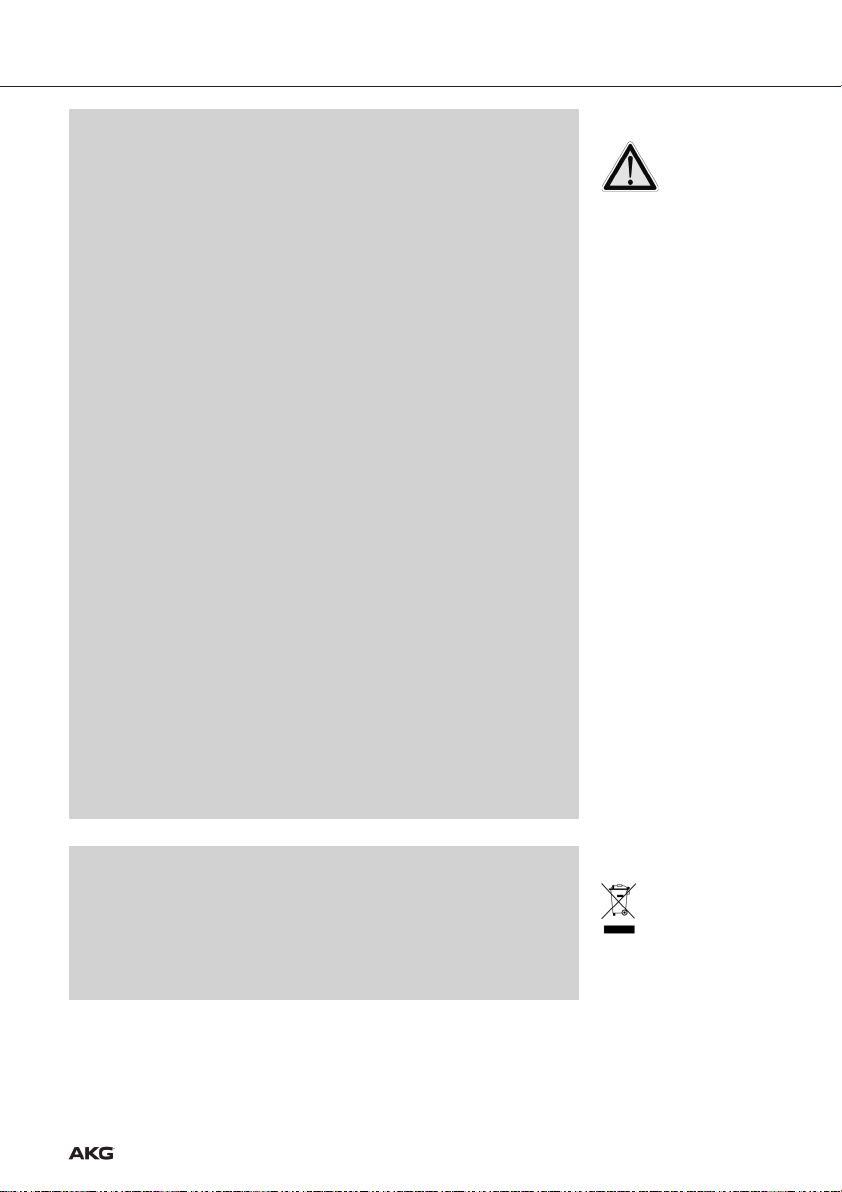
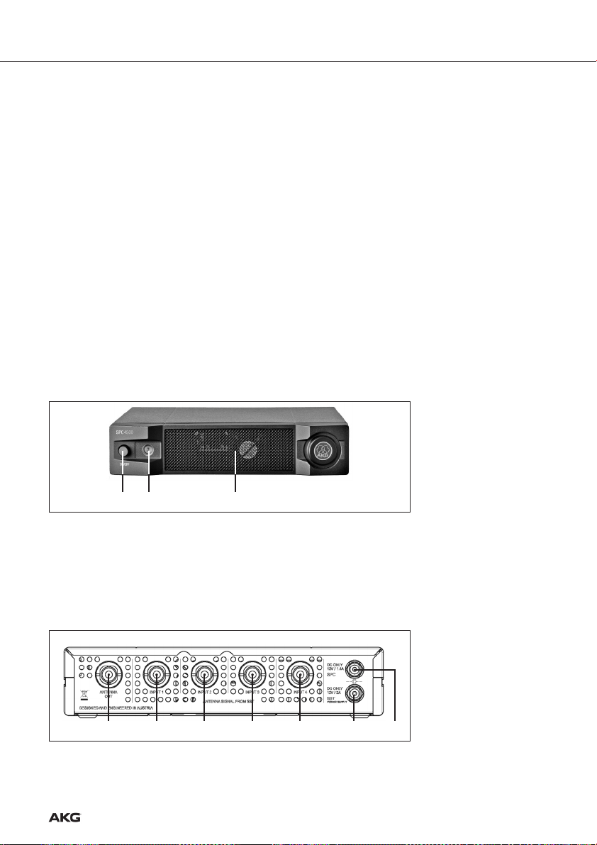
Fig. 1: Frontplatte
des SPC 4500
Siehe Fig. 1.
Vielen Dank, dass Sie sich für ein Produkt aus dem Hause AKG entschieden haben. Bitte
lesen Sie die Bedienungsanleitung aufmerksam durch, bevor Sie das Gerät benützen, und bewahren Sie die Bedienungsanleitung sorgfältig auf, damit Sie jederzeit nach-
schlagen können.
1 Antennencombiner SPC 4500
1 19"-Montageset
• Kontrollieren Sie bitte, ob die Verpackung alle oben angeführten Teile enthält. Falls
etwas fehlt, wenden Sie sich bitte an Ihren AKG-Händler.
• Optionales Zubehör finden Sie im aktuellen AKG-Katalog/Folder oder auf
www.akg.com. Ihr Händler berät Sie gerne.
Der SPC 4500 ist ein Antennen-Combiner für das In-Ear Monitorsystem IVM 4500 IEM.
Der Antennen-Combiner erlaubt Ihnen, die Ausgangssignale von bis zu vier Stereosendern
SST 4500 IEM zu einem gemeinsamen Antennensignal zu kombinieren. Der SPC 4500
funktioniert nur mit der passiven Richtantenne SRA 2 W und der passiven omnidirektionalen Sendeantenne RA 4000 W.
Die Stromversorgung erfolgt entweder durch ein Netzgerät mit einer Sekundärspannung
von 12 V DC/1,4 A (nicht mitgeliefert) oder die zentrale Stromversorgung PSU 4000.
12 3
1 ON/OFF: Taste zum Ein- und Ausschalten des Geräts.
2 Status-LED: Diese dreifarbige LED zeigt folgende Betriebszustände an:
Grün: Gerät ist eingeschaltet, Betriebstemperatur im normalen Bereich.
Orange: Kritische Betriebstemperatur, es besteht die Gefahr der Überhitzung.
Rot: Das Gerät ist überhitzt oder es ist keine AKG-Antenne an das Gerät angeschlos-
sen. Schalten Sie das Gerät aus, um Schäden zu vermeiden.
3 Lüftergitter: Das Gerät verfügt über einen eingebauten Lüfter zur Kühlung der
Elektronik.
Rückseite
Fig. 2: Ein- und Ausgänge an
der Rückseite des SPC 4500
Siehe Fig. 2.
4
4 5 5 5 5 76
4 ANTENNA OUT: BNC-Ausgang für Sendeantenne SRA 2 W oder RA 4000 W. Sie kön-
nen diesen Ausgang auch mit einem Sendereingang eines weiteren SPC 4500 verbinden.
5 INPUT 1-4:
BNC-Eingänge zum Anschluss von bis zu vier Stereosendern SST 4500 IEM.
Page 5

6 DC ONLY 12 V/1.4 A SPC: DC-Eingang für Netzgerät 12 V DC/1,4 A (nicht mitgelie-
fert) zur Stromversorgung des SPC 4500.
7 DC ONLY 12 V/2 A SST:
Stromversorgung PSU 4000 zur Versorgung der angeschlossenen Sender SST 4500 IEM.
DC-Eingang zum Anschluss der optionalen zentralen
2 Beschreibung
5
Page 6
3 Inbetriebnahme
Wichtige Hinweise
Rackmontage eines
Antennen-Combiners
Siehe Fig. 6.
Rackmontage zweier
Antennen-Combiner
nebeneinander
Siehe Fig. 7.
1. Stellen Sie sämtliche Antennenkabelverbindungen her, bevor Sie das Gerät mit
der Stromversorgung verbinden.
2. Schließen Sie an den SPC 4500 keine andere Antenne an als SRA 2 W oder
RA 4000 W von AKG. Die Verwendung anderer Antennen führt zu Fehlfunktionen des SPC 4500.
3. Verwenden Sie möglichst kurze Antennenkabel (max. 10 m).
4. Stellen Sie das Gerät so auf, dass das Lüftergitter an der Frontplatte nicht verdeckt werden kann. Eine blockierte Luftzufuhr kann zur Überhitzung des
Gerätes führen.
1. Schrauben Sie die vier Gummifüße (1) von der Unterseite des Antennen-Combiners
ab.
2. Schrauben Sie die beiden Befestigungsschrauben (2) von jeder der beiden
Seitenwände ab.
3. Befestigen Sie mit den Schrauben (2) den kurzen Montagewinkel (3) an der einen
Seitenwand und den langen Montagewinkel (4) aus dem mitgelieferten Montageset
an der anderen Seitenwand.
4. Befestigen Sie den Antennen-Combiner im Rack.
1. Schrauben Sie die vier Gummifüße (1) von der Unterseite beider Antennen-Combiner
ab und nehmen Sie die Schrauben (5) aus den Gummifüßen (1) heraus.
2. Schrauben Sie die beiden Befestigungsschrauben (2) von der rechten Seitenwand des
einen Antennen-Combiners und von der linken Seitenwand des anderen AntennenCombiners ab.
3. Schieben Sie einen Verbindungsteil (4) durch je einen freien Schlitz in der Seitenwand
des ersten Antennen-Combiners, so dass das Befestigungsloch im Verbindungsteil
mit dem Gewindeloch in der Unterseite des Antennen-Combiners fluchtet.
4. Fixieren Sie die beiden Verbindungsteile (4) mit zwei der Schrauben (5) (aus den
Gummifüßen) am ersten Antennen-Combiner.
5. Verbinden Sie die beiden Antennen-Combiner, indem Sie die Verbindungsteile (4) am
ersten Antennen-Combiner durch die freien Schlitze in der Seitenwand des zweiten
Antennen-Combiners schieben, bis das Befestigungsloch in beiden Verbindungsteilen
(4) mit dem entsprechenden Gewindeloch in der Unterseite des zweiten AntennenCombiners fluchtet.
6. Fixieren Sie die Verbindungsteile (4) mit zwei der Schrauben (5) aus den Gummifüßen
(1) am zweiten Antennen-Combiner.
7. Schrauben Sie mit je zwei der Schrauben (2) aus den Seitenwänden je einen kurzen
Montagewinkel (6) an die äussere Seitenwand jedes Antennen-Combiners.
8. Befestigen Sie die Antennen-Combiner im Rack.
Antennen aufstellen
Aufstellungsort
6
Die folgenden Hinweise zur Antennenaufstellung gelten für alle Mehrkanalanlagen unabhängig von der Anzahl der Kanäle.
Reflexionen des Sendersignals an Metallteilen, Wänden, Decken, etc. oder Abschattungen
durch menschliche Körper können das direkte Sendersignal schwächen bzw. auslöschen.
Positionieren Sie die Antennen daher wie folgt:
1. Positionieren Sie die Antenne immer in der Nähe des Aktionsbereichs (Bühne).
2. Positionieren Sie die Antenne in einem Abstand von mehr als 1,5 m von großen
metallenen Gegenständen, Draht (besonders Maschendraht!) oder Metallblechen,
Wänden, Bühnengerüsten, Decken, u.ä.
3. Stellen Sie die Antenne nicht in Wandnischen.
4. Positionieren Sie die Antenne mindestens 1,5 m von Hochfrequenz abstrahlenden
Geräten wie Licht-Racks, Leuchtstoffröhren, digitalen Effektgeräten und PCs entfernt.
Page 7
3 Inbetriebnahme
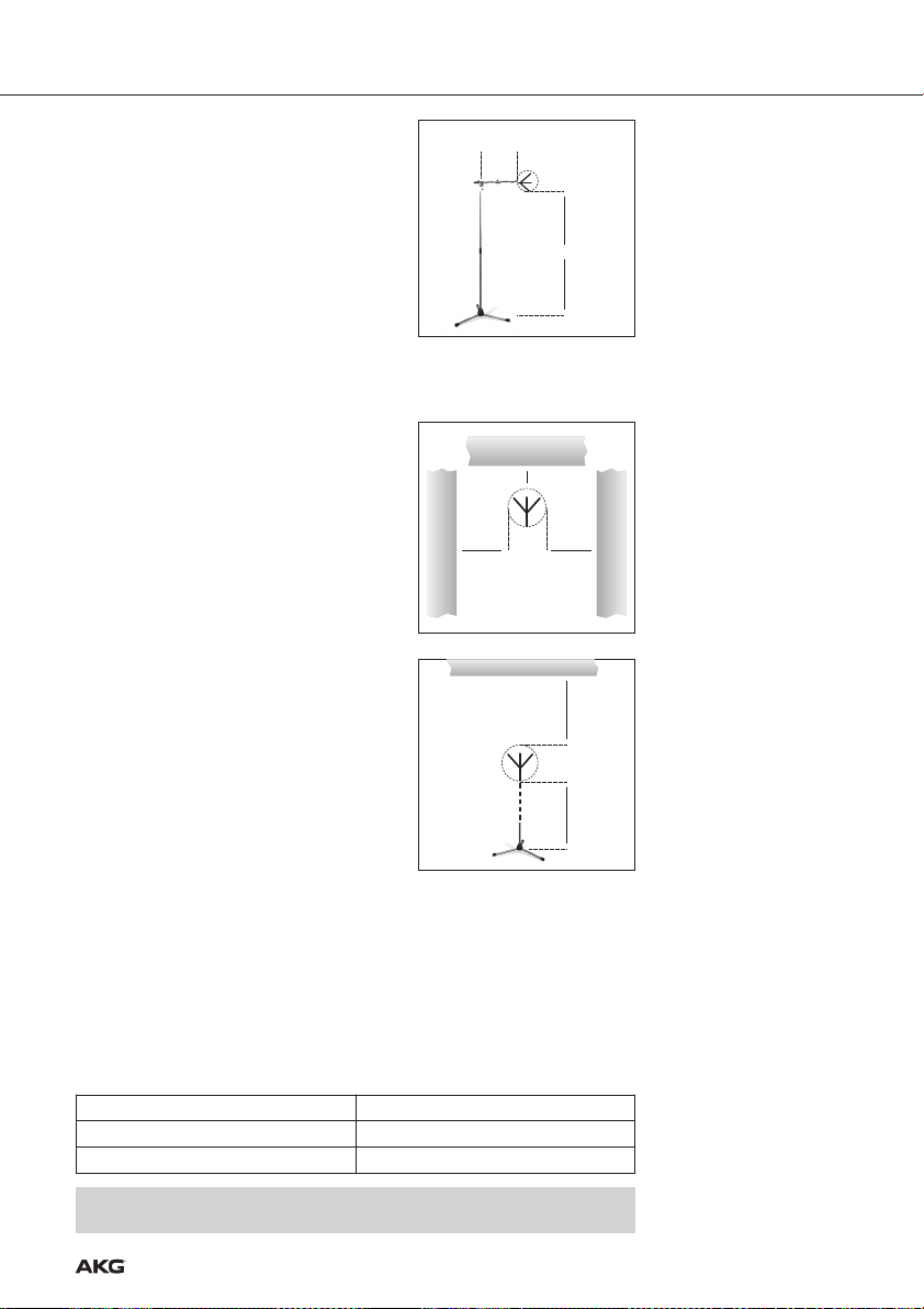
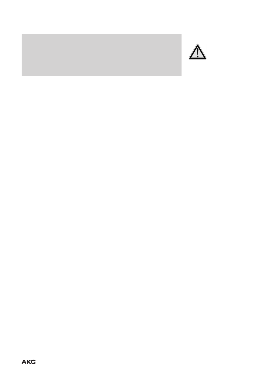
• Wenn Sie die Antenne auf einem Bodenstativ
montieren, beachten Sie bitte folgende Hinweise:
1. Befestigen Sie die Antenne mit dem mitgeliefer-
≥
70cm
˛
˛
˛
ten Stativanschluss SA 63 bzw. mit dem integrierten Stativanschluss am Ausleger eines
Galgenstativs.
≥150cm
2. Ziehen Sie den Ausleger ganz auf eine Seite,
damit die Antenne mindestens 70 cm vom Stativ
entfernt ist.
˛
3. Ziehen sie das Stativ soweit aus, dass sich der
Ausleger mindestens 1,8 m über dem Boden befindet.
4. Wickeln Sie das Antennenkabel um den Ausleger. Das Kabel darf nicht herunterhängen, da es sonst die Empfangsqualität beeinträchtigen kann.
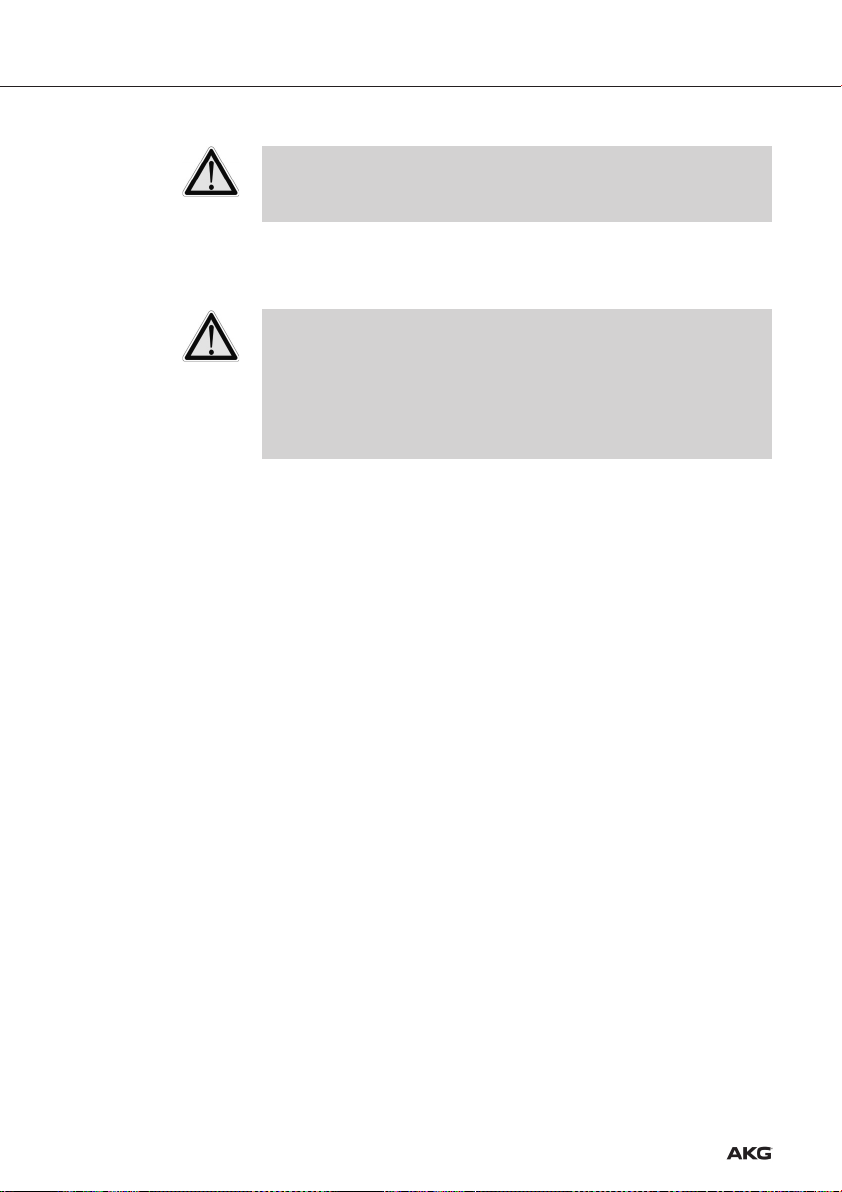
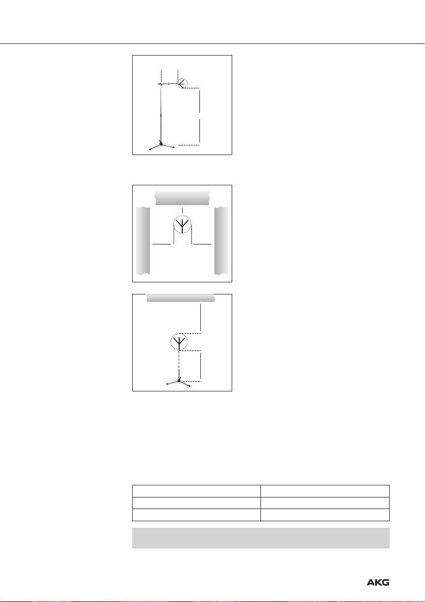
1. Montieren Sie die Antenne mindestens 10 cm vor
bzw. in einem seitlichen Abstand von mindestens
50 cm von Wänden oder anderen ebenen
Flächen bzw. Metallgittern oder Metallgerüsten.
˛
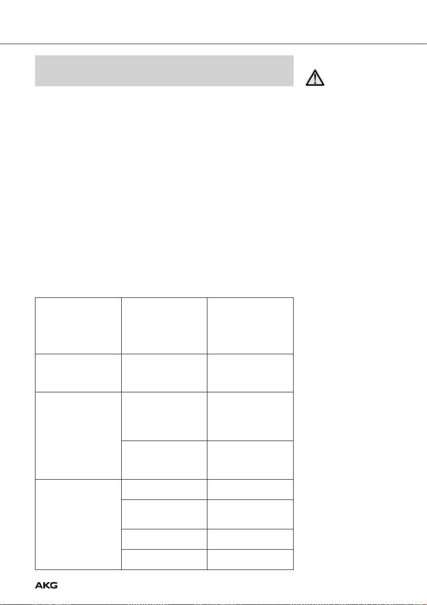
2. Achten Sie darauf, dass die Antenne mindestens
15 cm vom Boden bzw. 50 cm (bei Kabelzuführung von oben: 15 cm) von der Decke entfernt
ist.
≥ 50cm
˛
≥10cm
˛
˛
≥50 (15) cm
˛
≥ 50cm
˛
˛
˛
Montage auf Bodenstativ
Fig. 3: Antenne auf
Bodenstativ montiert
Wand-/Deckenmontage
Fig. 4: Mindestabstand von
ebenen Flächen
˛
≥ 15cm
˛
1. Verbinden Sie den ANTENNA-Ausgang jedes Senders mit einer der INPUT-Buchsen
am Antennen-Combiner.
Verwenden Sie dazu möglichst kurze Antennenkabel (max. 10 m), z.B. RG58 oder
RG213.
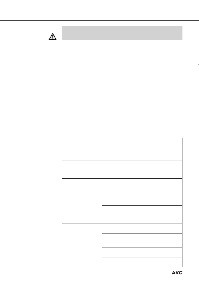
2. Wenn mehrere Signale über eine gemeinsame Antenne abgestrahlt werden, entstehen Störstrahlungen durch Intermodulation der einzelnen Trägerfrequenzen.
Um technische und rechtliche Probleme (Grenzwerte für Sendeleistung und
Störstrahlung) zu vermeiden, stellen Sie an jedem Sender die Sendeleistung (RF OUTPUT) wie folgt ein (siehe Bedienungsanleitung IVM 4500 IEM):
Anzahl der Sender Max. Sendeleistung pro Sender
2 –4 20 mW
≥4 10 mW
• Falls Sie Mehrkanalanlagen mit höheren Leistungen verwenden wollen, wenden Sie
sich bitte an den AKG Vertrieb unter sales@akg.com.
Fig. 5: Mindestabstand von
Boden und Decke
Verkabelung
7
Page 8
3 Inbetriebnahme
3. Verbinden Sie die Antenne mit der ANTENNA OUT-Buchse am Antennen-Combiner.
• Beachten Sie bitte, dass die Antenne die abgestrahlte Leistung (ERP) in ihrer
Vorzugsrichtung anheben kann. Um die erlaubten Grenzwerte nicht zu überschreiten, achten Sie auf die richtige Länge der Antennenkabel je nach verwendetem Kabeltyp, z.B. RG58: 5 m für RA 4000 W oder 10 m für SRA 2 W.
Stromversorgung
Siehe Fig. 8 auf Seite 57 und
Bedienungsanleitung
des PSU 4000.
• Sie können den Antennen-Combiner entweder mit einem geeigneten Netzgerät oder
mit der optionalen Stromversorgung PSU 4000 betreiben.
• Verwenden Sie für den SPC-Versorgungseingang nur ein Netzgerät mit 12 V DC
Sekundärspannung und einer Belastbarkeit von mindestens 1,4 A.
• Kontrollieren Sie, ob die am Netzgerät angegebene Netzspannung mit der
Netzspannung am Einsatzort übereinstimmt. Der Betrieb des Netzgeräts an
einer anderen Netzspannung kann zu irreparablen Schäden am Gerät führen.
• Wenn Sie am SST-Versorgungseingang weder ein passendes Netzgerät noch
ein PSU 4000 anschließen, müssen Sie alle Sender mit einem separaten
Netzgerät betreiben.
1. Verbinden Sie das DC-Kabel des 1,4-A-Netzgeräts oder den DC-Ausgang des
PSU 4000 mit der Buchse DC ONLY 12 V/1.4 A SPC an der Rückseite des AntennenCombiners.
2. Verbinden Sie das DC-Kabel des 2-A-Netzgeräts oder den DC-Ausgang des
PSU 4000 mit der Buchse DC ONLY 12 V/2 A SST an der Rückseite des AntennenCombiners.
3. Verbinden Sie das Netzgerät/PSU 4000 mit einer geeigneten Netzsteckdose.
8
Page 9
4 Betriebshinweise
• Halten Sie beim Ein- und Ausschalten der Anlage die im Folgenden angegebene Reihenfolge unbedingt ein, um Schäden durch Überlastung der
Stromversorgung des Antennen-Combiners zu vermeiden.
Einschalten:
1. Schalten Sie den Antennen-Combiner ein, indem Sie die ON/OFF-Taste drücken.
Die Status-LED leuchtet grün auf.
2. Schalten Sie alle mit dem Antennen-Combiner verbundenen Sender ein.
Ausschalten:
1. Schalten Sie alle mit dem Antennen-Combiner verbundenen Sender aus.
2. Schalten Sie den Antennen-Combiner aus, indem Sie die ON/OFF-Taste drücken.
Die Status-LED erlischt.
Einschalten:
1. Schalten Sie die zentrale Stromversorgung PSU 4000 ein.
2. Schalten Sie den Antennen-Combiner ein, indem Sie die ON/OFF-Taste drücken.
Die Status-LED leuchtet grün auf.
3. Schalten Sie alle mit dem Antennen-Combiner verbundenen Sender ein.
Ausschalten:
1. Schalten Sie alle mit dem Antennen-Combiner verbundenen Sender aus.
2. Schalten Sie den Antennen-Combiner aus, indem Sie die ON/OFF-Taste drücken.
Die Status-LED erlilscht.
3. Schalten Sie die zentrale Stromversorgung PSU 4000 aus.
Der Antennen-Combiner ist
eingeschaltet und mit einer
Grün
Orange
Rot
Dunkel
von AKG zugelassenen
Antennne verbunden. Die
Betriebstemperatur liegt im
normalen Bereich.
Die Betriebstemperatur hat
einen kritischen Wert
erreicht.
Der Antennen-Combiner ist
überhitzt.
An den Antennen-Combiner
ist eine nicht von AKG zugelassene Antenne angeschlossen.
Der Antennen-Combiner ist
ausgeschaltet.
Der Antennen-Combiner ist
nicht mit der Stromversorgung verbunden.
DC-Kabel ist/sind nicht
angeschlossen oder defekt.
Netzgerät oder PSU 4000
ist defekt.
Schalten Sie den AntennenCombiner aus und überprüfen Sie, ob das Lüftergitter
frei ist.
Schalten Sie den AntennenCombiner aus und überprüfen
Sie, ob das Lüftergitter frei
und die Stromversorgung
korrekt angeschloosen ist.
Schalten Sie den AntennenCombiner aus und schließen
Sie eineAntenne
SRA 2 W oder RA 4000 W an.
Schalten Sie den AntennenCombiner ein.
Verbinden Sie den
Antennen-Combiner mit der
Stromversorgung.
DC-Kabel anschließen oder
austauschen.
Wenden Sie sich an Ihre
AKG-Servicestelle.
Ein- und ausschalten
Anlagen mit dezentraler
Stromversorgung
Anlagen mit optionaler
zentraler Stromversorgung
PSU 4000
Status-LED
9
Page 10
5 Reinigung
6 Technische Daten
1. Trennen Sie das Gerät von der Stromversorgung.
2. Reinigen Sie die Oberflächen des Gerätes mit einem mit Wasser befeuchteten, aber
nicht nassen Tuch.
• Verwenden Sie keinesfalls scharfe oder scheuernde Reinigungsmittel sowie
keine, die Alkohol oder Lösungsmittel enthalten, da diese den Lack sowie die
Kunststoffteile beschädigen könnten.
Typ: 4:1 Antennen-Combiner
Trägerfrequenzbereich: 500 - 865 MHz
System Gain: 0 dB
HF-Eingänge: 4 BNC-Buchsen, 50 Ohm
HF-Ausgang: 1 BNC-Buchse, 50 Ohm
Betriebsspannung: 12 VDC/1,4 A
Stromversorgung (für SST 4500 IEM): 12 VDC/2 A
Abmessungen: 200 x 190 x 44 mm
Gewicht: 1193 g
Dieses Produkt entspricht den in der Konformitätserklärung angegebenen Normen. Sie
können die Konformitätserklärung auf http://www.akg.com oder per E-Mail an
sales@akg.com anfordern.
10
Page 11

FCC Statement . . . . . . . . . . . . . . . . . . . . . . . . . . . . . . . . . . . . . . . . . . . . . . . . . 11
1 Safety and Environment . . . . . . . . . . . . . . . . . . . . . . . . . . . . . . . . . . . . . . . 12
Safety . . . . . . . . . . . . . . . . . . . . . . . . . . . . . . . . . . . . . . . . . . . . . . . . . . . . . 12
Environment . . . . . . . . . . . . . . . . . . . . . . . . . . . . . . . . . . . . . . . . . . . . . . . . . 12
2 Description . . . . . . . . . . . . . . . . . . . . . . . . . . . . . . . . . . . . . . . . . . . . . . . . . 13
Introduction . . . . . . . . . . . . . . . . . . . . . . . . . . . . . . . . . . . . . . . . . . . . . . . . . 13
Packing List . . . . . . . . . . . . . . . . . . . . . . . . . . . . . . . . . . . . . . . . . . . . . . . . . 13
Optional Accessories. . . . . . . . . . . . . . . . . . . . . . . . . . . . . . . . . . . . . . . . . . . 13
SPC 4500 . . . . . . . . . . . . . . . . . . . . . . . . . . . . . . . . . . . . . . . . . . . . . . . . . . 13
Front Panel . . . . . . . . . . . . . . . . . . . . . . . . . . . . . . . . . . . . . . . . . . . . . . . 13
Rear Panel . . . . . . . . . . . . . . . . . . . . . . . . . . . . . . . . . . . . . . . . . . . . . . . . 13
3 Getting Started . . . . . . . . . . . . . . . . . . . . . . . . . . . . . . . . . . . . . . . . . . . . . . 15
Important Notes . . . . . . . . . . . . . . . . . . . . . . . . . . . . . . . . . . . . . . . . . . . . . . 15
3Rack Mounting a Single Antenna Combiner . . . . . . . . . . . . . . . . . . . . . . . . . 15
Rack Mounting Two Antenna Combiners Side by Side . . . . . . . . . . . . . . . . . . . 15
Setting Up Antennas . . . . . . . . . . . . . . . . . . . . . . . . . . . . . . . . . . . . . . . . . . . 15
Placement . . . . . . . . . . . . . . . . . . . . . . . . . . . . . . . . . . . . . . . . . . . . . . . . 15
Mounting Antennas on Floor Stands . . . . . . . . . . . . . . . . . . . . . . . . . . . . . 16
Wall/Ceiling Mounting. . . . . . . . . . . . . . . . . . . . . . . . . . . . . . . . . . . . . . . . 16
Wiring . . . . . . . . . . . . . . . . . . . . . . . . . . . . . . . . . . . . . . . . . . . . . . . . . . . . . 16
Powering . . . . . . . . . . . . . . . . . . . . . . . . . . . . . . . . . . . . . . . . . . . . . . . . . . . 17
4 Operating Notes . . . . . . . . . . . . . . . . . . . . . . . . . . . . . . . . . . . . . . . . . . . . . 18
Powering Up/Down . . . . . . . . . . . . . . . . . . . . . . . . . . . . . . . . . . . . . . . . . . . . 18
Systems with Distributed Power Supplies. . . . . . . . . . . . . . . . . . . . . . . . . . 18
Systems with PS 4000 Central Power Supplies . . . . . . . . . . . . . . . . . . . . . 18
Status LED . . . . . . . . . . . . . . . . . . . . . . . . . . . . . . . . . . . . . . . . . . . . . . . . . . 18
Table of Contents
5 Cleaning . . . . . . . . . . . . . . . . . . . . . . . . . . . . . . . . . . . . . . . . . . . . . . . . . . . 19
6 Specifications. . . . . . . . . . . . . . . . . . . . . . . . . . . . . . . . . . . . . . . . . . . . . . . 19
Figs. 6 – 8 . . . . . . . . . . . . . . . . . . . . . . . . . . . . . . . . . . . . . . . . . . . . . . . . . . . . 56
11
Page 12
1 Safety and Environment
1 Safety
1. Do not expose it to direct sunlight, excessive dust, moisture, rain, mechanical vibrations, or shock.
2. Do not spill any liquids on the equipment and do not drop any objects through the
ventilation slots in the equipment.
3. The equipment may be used in dry rooms only.
4. The equipment may be opened, serviced, and repaired by authorized personnel only.
The equipment contains no user-serviceable parts.
5. Before connecting the equipment to power, check that the primary voltage stated on
your power supply is identical to the AC mains voltage available where you will use
the equipment.
6. Operate the equipment with a DC power supply with an output voltage of 12 VDC/
1.4 A or the PSU 4000 central power supply from AKG. Using a power supply with a
different output voltage may cause serious damage to the unit.
7. If any solid object or liquid penetrates into the equipment, shut down the sound system immediately. Disconnect the equipment from the power outlet immediately and
have the equipment checked by AKG service personnel.
7. If you will not use the equipment for a long period of time, disconnect the equipment
from the power outlet. Please note that the equipment will not be fully isolated from
power when you set the power switch to OFF.
9. Do not place the equipment near heat sources such as radiators, heating ducts, or
amplifiers, etc. and do not expose it to direct sunlight, excessive dust, moisture, rain,
mechanical vibrations, or shock.
10. To avoid damage due to overheating, make sure never to cover or block the ventilation louvers on the equipment front panel.
11. To avoid hum or interference, route all cables away from power lines of any type. If
you use cable ducts, be sure to use separate ducts for the audio lines.
12. Clean the equipment with a moistened (not wet) cloth only. Be sure to disconnect the
AC adapter from the power outlet before cleaning the equipment! Never use caustic
or scouring cleaners or cleaning agents containing alcohol or solvents since these
may damage the enamel and plastic parts.
13. Use the equipment for the applications described in this manual only. AKG cannot
accept any liability for damages resulting from improper handling or misuse.
Environment
12
1. The AC adapter will draw a small amount of current even when the equipment is
switched off. To save energy, disconnect the AC adapter from the power outlet if you
will leave the equipment unused for a long period of time.
2. When scrapping the equipment, separate the case, circuit boards, and cables, and
dispose of all components in accordance with local waste disposal rules.
3. The packaging of the equipment is recyclable. Dispose of the packaging in an appropriate container provided by the local waste collection/recycling entity and observe all
local legislation relating to waste disposal and recycling.
Page 13
2 Description
Thank you for purchasing an AKG product.This Manual contains important instructions for
setting up and operating your equipment. Please take a few minutes to read the instruc-
tions below carefully before operating the equipment and keep the Manual for future
reference.
1 SPC 4500 antenna combiner
1 19" rack mounting kit
• Check that the packaging contains all of the items listed above. Should any of these
items be missing, please contact your AKG dealer.
• For optional accessories, refer to the current AKG catalog or folder, or visit
www.akg.com. Your dealer will be glad to help.
The SPC 4500 is an antenna combiner designed for the IVM 4500 IEM in-ear monitor
system. The antenna combiner allows you to combine the output signals of up to four
SST 4500 IEM stereo transmitters into a single antenna signal. The SPC 4500 will only
operate with the SRA 2 W passive directional antenna or RA 4000 W passive omnidirectional antenna from AKG.
The SPC 4500 can be powered either from an AC adapter with an output voltage of
12 VDC/1.4 A (not included) or the optional PSU 4000 central power supply.
Introduction
Packing List
Optional Accessories
SPC 4500
Front Panel
12 3
1 ON/OFF: Pushbutton for switching power to the unit on and off.
2 Status LED: This tricolor LED indicates the following operating conditions:
Green: Power to the unit is on, the operating temperature is within the safe range.
Orange: Critical operating temperature, the unit may overheat.
Red: The unit has overheated or is connected to an antenna not approved by AKG.
Switch power to the unit off to avoid damage to the unit.
3 Ventilation grill: The unit incorporates a ventilator for cooling the electronic circuitry.
4 5 5 5 5 76
4 ANTENNA OUT: BNC output connector for an SRA 2 W or RA 4000 W transmitting
antenna. You may also connect this output to a transmitter input on another
SPC 4500.
Fig. 1: SPC 4500 front panel.
Refer to fig. 1.
Rear Panel
Fig. 2: Inputs and outputs on
the SPC 4500 rear panel.
Refer to fig. 2.
13
Page 14

2 Description
5 INPUT 1-4: BNC inputs for connecting one to four SST 4500 IEM stereo transmitters.
6 DC ONLY 12 V/1.4 A SPC 4500: DC input for an AC adapter with a 12 VDC/1.4 A out-
put (not included) for powering the SPC 4500.
7 DC ONLY 12 V/2 A SST: DC input for connecting the optional PSU 4000 central power
supply for powering the SST 4500 IEM transmitters connected to the SPC 4500.
14
Page 15
3 Getting Started
1. Make all antenna cable connections before connecting the unit to power.
2. Do not connect to the SPC 4500 any antenna other than the SRA 2 W or
RA 4000 W from AKG. Using other antenna types may cause malfunctioning of
the SPC 4500.
3. Use the shortest possible antenna cables (33 ft./10 m max.).
4. Position the unit such that the front panel ventilation grill cannot be covered.
Obstructing the air intake may cause the unit to overheat.
1. Unscrew the four rubber feet (1) from the antenna combiner bottom panel.
2. Unscrew the two fixing screws (2) from each side panel.
3. Use the fixing screws (2) to screw the short bracket (3) to one side panel and the long
bracket (4) to the other side panel. The brackets are contained in the supplied rack
mounting kit.
4. Install the antenna combiner in your rack.
1. Unscrew the four rubber feet (1) from each antenna combiner's bottom panel and
remove the screws (5) from the rubber feet (1).
2. Unscrew the two fixing screws (2) from the right-hand side panel of one antenna combiner and from the left-hand side panel of the other antenna combiner.
3. Insert one connecting strip (4) into each free slot in the side panel of the first antenna combiner, making sure to align the hole in each connecting strip (4) with the appropriate threaded hole in the antenna combiner bottom panel.
4. Fix the two connecting strips (4) on the first antenna combiner using two of the screws
(5) you removed from the rubber feet.
5. To join the two antenna combiners, slide the connecting strips (4) on the first antenna combiner through the free slots in the side panel of the second antenna combiner. Make sure to align the hole in each connecting strip (4) with the appropriate
threaded hole in the bottom panel of the second antenna combiner.
6. Fix the two connecting strips (4) on the second antenna combiner using two of the
screws (5) you removed from the rubber feet.
7. Screw a short bracket (6) to the outer side panel of each antenna combiner using for
each bracket two of the screws (2) you removed from the antenna combiner side panels.
8. Install the antenna combiners in your rack.
Important Notes
Rack Mounting a
Single Antenna
Combiner
Refer to fig. 6.
Rack Mounting Two
Antenna Combiners
Side by Side
Refer to fig. 7.
The following hints on placing the antenna apply to any multichannel system, no matter
how many channels it may use.
Reflections off metal parts, walls, ceilings, etc. or the shadow effects of musicians and
other people may weaken or cancel the direct transmitter signal. For best results, place
the antenna as follows:
1. Place the antenna near the performance area (stage).
2. Place the antenna at least 5 ft. (1.5 m) away from any big metal objects, walls, scaffolding, ceilings, etc.
3. Do not place the antenna in a wall recess.
4. Place the antenna at least 5 ft. (1.5 m) away from any equipment that may emit RF
radiation such as lighting racks, fluorescent lamps, digital effects units, or PCs.
Setting Up Antennas
Placement
15
Page 16
3 Getting Started
Mounting Antennas
on Floor Stands
Fig. 3: Antenna mounted
on a floor stand.
Wall/Ceiling Mounting
Fig. 4: Minimum distances
from plane surfaces.
Fig. 5: Minimum distances
from floor and ceiling.
≥
70cm
˛
˛
˛
• When mounting the antenna on a floor stand, be
sure to proceed as follows:
1. Use the supplied SA 63 or the integrated stand
adapter to mount the antenna on the boom of a
boom stand.
≥150cm
2. Pull the boom out all the way to one side to make
sure the antenna will be at least 28 inches (70 cm)
away from the stand.
˛
3. Extend the stand high enough to place the boom
at least 6 ft. (1.8 m) above the floor.
4. Wind the antenna cable around the boom. Do not allow the cable to sag below the
boom because this may degrade the reception quality.
1. Mount the antenna at least 10 cm (4 in.) in front
of and at a minimum lateral distance of 50 cm
(20 in.) from any walls or other plane surfaces,
metal grids, or metal scaffolding.
2. Make sure the antenna will sit at least 15 cm
(6 in.) above the floor or 50 cm (20 in.) from the
ceiling (or 15 cm (6 in.) if you route the cable to
the antenna from above).
˛
≥ 50cm
˛
≥10cm
˛
˛
≥50 (15) cm
˛
≥ 50cm
˛
˛
˛
˛
≥ 15cm
˛
Wiring
1. Connect the ANTENNA output on each transmitter to one of the INPUT connectors on
the antenna combiner.
Use the shortest possible antenna cables (33 ft./10 m max.), e.g., RG58 or RG 213.
2. If several signals are radiated by a shared antenna, intermodulation of the various carrier frequencies will cause spurious emissions.
To avoid technical and legal problems (official limits for RF output and spurious emissions), set the RF OUTPUT level on each transmitter as follows (also refer to the
IVM 4500 IEM User Manual):
Transmitters Max. RF output per transmitter
2 –4 20 mW
≥4 10 mW
• If you need to use a multichannel system with a higher RF output, please contact AKG
Sales at sales@akg.com.
3. Connect the antenna to the ANTENNA OUT connector on the antenna combiner.
16
Page 17
• Please note that these antennas may boost their RF output (ERP) in their preferred directions. In order to keep RF output within legal limits, make sure to
use antenna cables of the correct length for each type of cable, e.g., RG58:
16 ft. (5 m) for an RA 4000 W or 33 ft. (10 m) for an SRA 2 W.
3 Getting Started
• To power the SPC 4500 you can use either a suitable AC adapter or the optional PSU
4000 central power supply.
• Do not connect to the SPC DC input any AC adapter other than a type delivering an output voltage of 12 VDC and an output current of 1.4 A or higher.
• Check that the AC mains voltage stated on your power supply is identical to the
AC mains voltage available where you will use your system. Using the power
supply with a different AC voltage may cause irreparable damage to the unit.
• If you connected neither a suitable standard AC adapter nor a PSU 4000 to
DC ONLY 12 V/2 A SST, you will need to power each transmitter from a separate power supply.
1. Connect the DC cable of a 1.4-A AC adapter or the DC output on the PSU 4000 to
the DC ONLY 12 V/1.4 A SPC jack on the antenna combiner rear panel.
2. Connect the DC cable of a 2-A AC adapter or the DC output on the PSU 4000 to the
DC ONLY 12 V/2 A SST jack on the antenna combiner rear panel.
3. Connect the AC adapter/PSU 4000 to a convenient AC outlet.
Powering
Refer to fig. 8 on page 57
and the PSU 4000 User
Manual.
17
Page 18
Powering Up/Down
• To prevent damage from overloading the antenna combiner power supply,
always switch power to the various components of your system on and off in
the order described below.
Systems with Distributed
Power Supplies
Systems with PSU 4000
Central Power Supplies
Status LED
Powering Up:
1. Press the ON/OFF key on the antenna combiner to switch power to the antenna combiner ON. The status LED will be lit green.
2. Switch ON all transmitters connected to the antenna combiner.
Powering Down:
1. Switch OFF all transmitters connected to the antenna combiner.
2. Press the ON/OFF key on the antenna combiner to switch power to the antenna combiner OFF.The status LED will extinguish.
Powering Up:
1. Switch the PSU 4000 central power supply ON.
2. Press the ON/OFF key on the antenna combiner to switch power to the antenna combiner ON. The status LED will be lit green.
3. Switch ON all transmitters connected to the antenna combiner.
Powering Down:
1. Switch OFF all transmitters connected to the antenna combiner.
2. Press the ON/OFF key on the antenna splitter to switch power to the antenna splitter
OFF. The status LED will extinguish.
3. Switch the PSU 4000 central power supply OFF.
The antenna combiner is
Green
Orange
Red
Off
ON and connected to an
antenna approved by AKG.
The operating temperature
is within the safe range.
The operating temperature
has reached a critical level.
The antenna combiner is
overheating.
The antenna connected to
the antenna combiner is not
a type approved by AKG
Power to the antenna combiner is OFF.
The antenna combiner is
not connected to a power
supply.
The DC cable(s) is/are not
connected or defective.
The AC adapter or
PSU 4000 is defective.
Switch power to the antenna
combiner OFF and make
sure that the ventilation grill
is not obstructed.
Switch power to the antenna combiner OFF and make
sure that the ventilation grill
is not obstructed and the
power supply is connected
correctly.
Switch power to the antenna combiner OFF and connect an SRA 2 W or
RA 4000 W antenna.
Switch power to the antenna
combiner ON.
Connect the antenna combiner to your power supply.
Connect or replace the DC
cable(s).
Contact your nearest AKG
Service Center.
18
Page 19

1. Disconnect the unit from power.
2. To clean the unit's surfaces, use a soft cloth moistened (not soaked!) with water.
• Never use any caustic or scouring cleaners or cleaning agents containing alcohol or solvents since these may damage enamel and plastic parts.
Type: 4 to 1 antenna combiner
Carrier range: 500 MHz to 865 MHz*
System gain: 0 dB
RF inputs: 4 BNC sockets, 50 ohms
RF outputs: 1 BNC socket, 50 ohms
Power requirement: 12 VDC/1.4 A
Power supply (for SST 4500 IEMs): 12 VDC/2 A
Dimensions: 200 x 190 x 44 mm (7.8 x 7.5 x 1.7 in.)
Weight: 1,193 g (2.63 lbs)
This product conforms to the standards listed in the Declaration of Conformity. To order a
free copy of the Declaration of Conformity, visit http://www.akg.com or contact
sales@akg.com.
* Users in the U.S. please note that frequency ranges available under current FCC rules
are limited to 500.1–607.9 MHz and 614.1–697.9 MHz.
5 Cleaning
6 Specifications
19
Page 20

Sommaire
1 Sécurité et écologie . . . . . . . . . . . . . . . . . . . . . . . . . . . . . . . . . . . . . . . . . . 21
Sécurité . . . . . . . . . . . . . . . . . . . . . . . . . . . . . . . . . . . . . . . . . . . . . . . . . . . . 21
Ecologie . . . . . . . . . . . . . . . . . . . . . . . . . . . . . . . . . . . . . . . . . . . . . . . . . . . . 21
2 Description . . . . . . . . . . . . . . . . . . . . . . . . . . . . . . . . . . . . . . . . . . . . . . . . . 22
Introduction . . . . . . . . . . . . . . . . . . . . . . . . . . . . . . . . . . . . . . . . . . . . . . . . . 22
Fournitures d’origine . . . . . . . . . . . . . . . . . . . . . . . . . . . . . . . . . . . . . . . . . . . 22
Accessoires optionnels . . . . . . . . . . . . . . . . . . . . . . . . . . . . . . . . . . . . . . . . . 22
SPC 4500 . . . . . . . . . . . . . . . . . . . . . . . . . . . . . . . . . . . . . . . . . . . . . . . . . . 22
Façade. . . . . . . . . . . . . . . . . . . . . . . . . . . . . . . . . . . . . . . . . . . . . . . . . . . 22
Face arrière . . . . . . . . . . . . . . . . . . . . . . . . . . . . . . . . . . . . . . . . . . . . . . . 22
3 Mise en service . . . . . . . . . . . . . . . . . . . . . . . . . . . . . . . . . . . . . . . . . . . . . 24
Remarques importantes . . . . . . . . . . . . . . . . . . . . . . . . . . . . . . . . . . . . . . . . 24
Montage en rack d’un combinateur d’antennes . . . . . . . . . . . . . . . . . . . . . . . 24
Montage en rack de deux combinateurs d’antennes juxtaposés. . . . . . . . . . . . 24
Installation de l'antenne . . . . . . . . . . . . . . . . . . . . . . . . . . . . . . . . . . . . . . . . 24
Lieu d’installation . . . . . . . . . . . . . . . . . . . . . . . . . . . . . . . . . . . . . . . . . . . 24
Montage sur pied . . . . . . . . . . . . . . . . . . . . . . . . . . . . . . . . . . . . . . . . . . . 25
Montage sur un mur/au plafond . . . . . . . . . . . . . . . . . . . . . . . . . . . . . . . . 25
Liaisons . . . . . . . . . . . . . . . . . . . . . . . . . . . . . . . . . . . . . . . . . . . . . . . . . . . . 25
Alimentation . . . . . . . . . . . . . . . . . . . . . . . . . . . . . . . . . . . . . . . . . . . . . . . . . 26
4 Instructions pour le fonctionnement . . . . . . . . . . . . . . . . . . . . . . . . . . . . . 27
Mise sous tension/hors tension . . . . . . . . . . . . . . . . . . . . . . . . . . . . . . . . . . . 27
Installations avec alimentation décentralisée . . . . . . . . . . . . . . . . . . . . . . . 27
Installations avec alimentation centrale PSU 4000 optionnelle. . . . . . . . . . . 27
Témoin LED . . . . . . . . . . . . . . . . . . . . . . . . . . . . . . . . . . . . . . . . . . . . . . . . . 27
5 Nettoyage . . . . . . . . . . . . . . . . . . . . . . . . . . . . . . . . . . . . . . . . . . . . . . . . . . 28
6 Caractéristiques techniques. . . . . . . . . . . . . . . . . . . . . . . . . . . . . . . . . . . . 28
Fig. 6 – 8 . . . . . . . . . . . . . . . . . . . . . . . . . . . . . . . . . . . . . . . . . . . . . . . . . . . . . 56
20
Page 21

1 Sécurité et écologie
1. Ne pas exposer l'équipement aux rayons directs du soleil, à la poussière, à l'humidité,
à la pluie, aux vibrations mécaniques et aux chocs.
2. Faites attention de ne pas renverser de liquide sur l’appareil et à ce que rien ne tombe
à l’intérieur par les fentes d’aération.
3. Cet appareil ne doit en aucun cas être utilisé dans un local humide.
4. Cet appareil ne peut être ouvert, entretenu et réparé que par le personnel technique
autorisé. On ne trouve à l’intérieur du boîtier aucun élément pouvant être entretenu,
réparé ou remplacé par un profane.
5. Avant de mettre l’appareil en service, vérifiez si la tension primaire indiquée sur votre
alimentation correspond bien à la tension secteur sur le lieu d’utilisation.
6. Utilisez l’appareil exclusivement avec un bloc secteur pour courant continu avec tension de sortie de 12 V c.c./1,4 A ou avec l’alimentation centrale PSU 4000 d’AKG.
Tout autre type de courant ou de tension pourraient entraîner des dégâts sérieux sur
l’appareil !
7. S’il arrive qu’un objet solide ou du liquide pénètre à l’intérieur de l’appareil mettez
immédiatement l’installation hors service. Dans ce cas débranchez aussitôt l’appareil
du secteur et faites-le contrôler par notre SAV.
8. Si vous ne devez pas utiliser l’appareil pendant un certain temps, débranchez-le du
secteur.Il ne suffit pas d’éteindre l’appareil pour le couper complètement du secteur.
9. Ne placez jamais l’appareil à proximité d’une source de chaleur (radiateur, tuyaux de
chauffage, amplificateurs, etc.) ni à un endroit où il risque d’être exposé directement
au soleil, à une atmosphère poussiéreuse, à l’humidité, à la pluie, aux vibrations ou
aux secousses.
10. Pour éviter les dégâts susceptibles d’être causés par une surchauffe veillez à ce que
la grille du ventilateur en face avant ne soit jamais recouverte.
11. Pour éviter les parasites et les interférences, posez tous les fils séparément des
câbles de puissance et des lignes de secteur. En cas de pose dans un puits ou une
conduite pour câbles, les câbles de transmission devront toujours être posés dans
une conduite séparée.
12. Pour nettoyer l’appareil, utilisez un chiffon légèrement humide, jamais un chiffon
mouillé. N’oubliez surtout pas de débrancher auparavant l’adaptateur secteur !
N’utilisez jamais de produits de nettoyage mordants ou abrasifs, non plus que des
produits contenant de l’alcool ou un solvant qui risqueraient d’abîmer la laque et les
éléments en plastique.
13. N’utilisez jamais l'appareil pour une application autre que celles indiquées dans le
mode d’emploi. AKG décline toute responsabilité concernant les dégâts qui résulteraient d’une manipulation inappropriée ou d’une utilisation non conforme.
Sécurité
1. L’adaptateur secteur consomme toujours un peu de courant même lorsque l’appareil
est hors tension. Pour économiser le courant, pensez donc à débrancher l’adaptateur
secteur lorsque l’appareil restera un certain temps sans être utilisé.
2. Si vous mettez l'appareil à la ferraille, enlevez les piles ou les accus, séparez le boîtier, l'électronique et les câbles et éliminez les différents éléments conformément aux
règlements en vigueur.
3. L'emballage est recyclable. Déposez l'emballage dans un récipient de collecte prévu
à cet effet.
Ecologie
21
Page 22

2 Description
Introduction
Fournitures d’origine
Accessoires
optionnels
SPC 4500
Façade
Fig. 1 : Façade du SPC 4500
Voir Fig. 1.
Nous vous remercions d’avoir choisi un produit AKG. Pour profiter au maximum des avan-
tages que vous offre le SPC 4500, lisez très attentivement ce mode d’emploi
avant la mise en service de l’appareil. Conservez soigneusement le mode d’emploi pour pouvoir le consulter lorsque vous vous posez des questions.
1 combinateur d'antennes SPC 4500
1 kit de montage 19"
• Vérifiez que l’emballage contient bien tous les composants énumérés ci-dessus. Si
un élément manque, adressez-vous à votre revendeur AKG.
• Vous trouverez la liste des accessoires optionnels dans le catalogue/dépliant AKG
actuel ou sur www.akg.com. Votre fournisseur se tient à votre disposition pour vous
conseiller.
Le SPC 4500 est un combinateur d’antennes destiné au système moniteur à oreillettes
IVM 4500 IEM. Le combinateur d’antennes vous permet de combiner les signaux de sortie délivrés par jusqu’à quatre émetteurs stéréo SST 4500 IEM pour obtenir un signal
d’antenne commun. Le SPC 4500 fonctionne exclusivement avec l’antenne directive passive SRA 2 W et l’antenne émettrice omnidirectionnelle RA 4000 W.
L’alimentation est assurée soit par un bloc secteur avec tension secondaire de 12 V c.c./
1,4 A (n’est pas fourni avec le SPC 4500) ou avec l’alimentation centrale PSU 4000.
12 3
1 ON/OFF : Touche marche/arrêt.
2 Témoin LED : Cette LED tricolore indique les états suivants :
Vert : L’appareil est sous tension, la température de service est dans les limites nor-
males.
Orange : Température de service critique, risque de surchauffe.
Rouge : L’appareil chauffe ou bien il n’est pas raccordé à une antenne AKG. Mettez
l’appareil hors tension pour éviter les dégâts.
3 Grille du ventilateur : L’appareil dispose d’un ventilateur incorporé pour le refroidis-
sement de l’électronique.
Face arrière
Fig. 2 : Entrées et sorties sur
la face arrière du SPC 4500
Voir Fig. 2.
22
4 5 5 5 5 76
4 ANTENNA OUT : Sortie BNC pour antenne émettrice SRA 2 W ou RA 4000 W. Vous
pouvez aussi raccorder cette sortie à une entrée émetteur d’un autre SPC 4500.
Page 23

5 INPUT 1-4 : Entrées BNC permettant de raccorder jusqu’à quatre émetteurs stéréo
SST 4500 IEM.
6 DC ONLY 12 V/1.4 A SPC 4500 : Entrée c.c. pour bloc secteur 12 V c.c./1,4 A (ne
fait pas partie des fournitures d’origine) pour l’alimentation du SPC 4500.
7 DC ONLY 12 V/2 A SST : Entrée c.c. pour la connexion de l’alimentation centrale
optionnelle PSU 4000 destinée aux émetteurs SST 4500 IEM raccordés.
2 Description
23
Page 24

3 Mise en service
Remarques
importantes
Montage en rack d’un
combinateur
d’antennes
Voir Fig. 6.
Montage en rack de
deux combinateurs
d’antennes
juxtaposés
Voir Fig. 7.
1. Effectuez tous les raccordements de câbles d’antennes avant de connecter
l’appareil sur son alimentation.
2. Ne raccordez jamais au SPC 4500 une antenne autre que SRA 2 W ou RA 4000
W d’AKG. L’utilisation d’une autre antenne quelle qu’elle soit entraînerait un
disfonctionnement du SPC 4500.
3. N'utilisez que des câbles d'antenne les plus courts possible (≤10 m).
4. Installez l’appareil de manière à ce que la grille du ventilateur en face avant ne
soit pas recouverte. Si l’arrivée d’air était bloquée l’appareil risquerait de
chauffer.
1. Dévissez les quatre pieds de caoutchouc (1) se trouvant à la base du combinateur
d'antennes.
2. Dévissez les deux vis de fixation (2) se trouvant sur chacune des deux parois latérales.
3. Vissez sur l’une des faces latérales la cornière de montage courte 3, sur l’autre face
latérale la cornière de montage longue (4) ; ces cornières font partie du kit de montage fourni.
4. Fixez le combinateur d'antennes dans le rack.
1. Dévissez les quatre pieds de caoutchouc (1) se trouvant à la base du combinateur
d'antennes et sortez les vis (5) des pieds de caoutchouc (1).
2. Dévissez les deux vis de fixation (2) de la face latérale droite d’un combinateur d'antennes et les deux vis de fixation (2) de la face latérale gauche de l’autre combinateur d'antennes.
3. Introduisez un élément raccord (4) dans chacune des fentes libres de la paroi latérale
du premier combinateur d'antennes en veillant à ce que le trou de fixation de l’élément raccord coïncide avec le trou taraudé de la base du combinateur d'antennes.
4. Fixez les deux éléments raccord (4) au premier combinateur d'antennes à l’aide de
deux des vis (5) (qui se trouvaient dans les pieds de caoutchouc).
5. Réunissez les deux combinateurs d'antennes en introduisant chacun des éléments
raccord (4) du premier combinateur d'antennes dans une fente libre de la paroi latérale du second combinateur d'antennes, de manière à ce que le trou de fixation de
l’élément raccord (4) coïncide avec le trou taraudé de la base du combinateur d'antennes.
6. Fixez les éléments raccord (4) au second combinateur d'antennes à l’aide de deux
des vis (5) qui se trouvaient dans les pieds de caoutchouc 1.
7. Fixez une cornière de montage courte (6) sur la face latérale externe de chaque combinateur d'antennes en utilisant pour chacune deux vis (2) dévissées des faces latérales.
8. Fixez les combinateurs d'antennes dans le rack.
Les instructions ci-dessous concernant l’installation des antennes valent pour toutes les
installations multicanaux, quelque soit le nombre de canaux.
Installation
de l'antenne
Lieu d’installation
24
Les réflexions du signal de l’émetteur sur les surfaces métalliques, les murs, le plafond,
etc. de même que l’écran du corps humain risquent d’affaiblir voire supprimer le signal
direct de l’émetteur. Placez donc l’antenne comme suit :
1. Placez toujours l'antenne à proximité du lieu d’action (scène).
2. Placez l'antenne à plus de 1,5 m des objets métalliques volumineux, fils métalliques
(en particulier grillages) ou tôles, de même que des murs, des décors, du plafond, etc.
3. N’installez pas l'antenne dans des niches murales.
e placez jamais l'antenne à moins de 1,5 m des appareils émettant un rayonnement
4. N
HF tels que racks d’éclairage, tubes fluorescents, appareils à effets numériques ou PC.
Page 25

•
Si vous montez l'antenne sur un pied, veuillez
tenir compte des remarques suivantes :
1. Fixez l'antenne à la perche d’un pied à l’aide de
l’élément raccord SA 63 fourni ou du raccord
intégré.
2. Tirez la perche à fond d’un côté pour que l’antenne se trouve à 70 cm au moins du pied.
3. Déployez le pied télescopique pour que la perche
se trouve à 1,8 m au moins du sol.
4. Enroulez le câble d’antenne sur la perche. Avec
un câble qui pend vous risquez d’avoir une mauvaise réception.
3 Mise en service
≥
70cm
˛
˛
˛
≥150cm
˛
Montage sur pied
Fig. 3 : Antenne montée sur
pied
1. Placez l’antenne à une distance aux murs,
parois, grilles métalliques ou échaffaudages de
métal de
10 cm au minimum sur l’arrière et 50 cm latérale-
˛
˛
≥10cm
ment.
2. Veillez à ce que l’antenne se trouve à une distance minimum de 15 cm du sol ou 50 cm du
plafond (15 cm si le câble arrive par le haut).
˛
≥
50cm
˛
≥50 (15) cm
˛
˛
≥
50cm
˛
˛
˛
≥ 15cm
˛
1. Reliez la sortie ANTENNA de chaque émetteur à une prise INPUT du combinateur
d’antennes.
Utilisez à cet effet un câble d’antenne, p.ex. RG58 ou RG213, aussi court que possible.
2. Lorsque plusieurs signaux passent par une antenne commune, l’intermodulation des
différentes porteuses provoque des rayonnements parasites.
Pour éviter les problèmes techniques et légaux (seuils autorisés pour la puissance
d’émission et les rayonnements parasites) réglez la puissance d’émission (RF OUTPUT) comme suit sur chaque émetteur (voir notice d’emploi de l’IVM 4500 IEM):
Montage sur un mur/au
plafond
Fig. 4 : Distance minimum
d’une surface plane
Fig. 5 : Distance minimum du
sol et du plafond
Liaisons
Nombre d#émetteurs Puissance d’émission maxi.par émetteur
2 –4 20 mW
≥4 10 mW
• Si vous souhaitez utiliser des installations multicanaux à puissance élevée, veuillez
consulter le service des ventes d’AKG en tapant sales@akg.com.
3. Reliez l’antenne à la prise ANTENNA OUT sur le combinateur d'antennes.
25
Page 26

3 Mise en service
• N’oubliez pas que l’antenne peut augmenter la puissance rayonnée (ERP) dans
sa direction prédominante. Pour ne pas dépasser les limites autorisées, veillez
à ce que le câble d’antenne ait la longueur voulue suivant le type de câble utilisé, p.ex. RG58 : 5 m pour RA 4000 W ou 10 m pour SRA 2 W.
Alimentation
Voir Fig. 8 (page 57) et notice
d’emploi du PSU 4000.
• Vous pouvez utiliser le combinateur d’antennes au choix avec un bloc secteur approprié ou avec l’alimentation PSU 4000 optionnelle.
• Reliez à l'entrée d'alimentation SPC exclusivement un bloc secteur avec tension secondaire de 12 V c.c. d’une capacité minimum de 1,4 A.
• Vérifiez si la tension secteur indiquée sur le bloc secteur concorde avec la tension secteur sur le lieu d’utilisation. En les utilisant sur une tension secteur différente, vous risquez des dégâts sur l’installation.
• Si vous avez branché ni un bloc secteur standard approprié ni un PSU 4000 sur
la prise d'alimentation SST, il faut utiliser chaque émetteur avec un bloc secteur individuel.
1. Reliez le câble c.c. du bloc secteur 1,4 A ou la sortie DC du PSU 4000 à la prise
DC ONLY 12 V/1.4 A SPC en face arrière du combinateur d'antennes.
2. Reliez le câble c.c. du bloc secteur 2 A ou la sortie DC du PSU 4000 à la prise
DC ONLY 12 V/2 A SST du combinateur d’antennes.
3. Branchez le bloc secteur/PSU 4000 sur une prise secteur appropriée.
26
Page 27

4 Instructions pour le fonctionnement
• Pour mettre l’installation sous tension et hors tension, procédez impérativement dans l’ordre indiqué aux points ci-dessous afin d’éviter toute détérioration due à une surcharge de l’alimentation du combinateur d’antennes.
Mise sous tension :
1. Mettez le combinateur d’antennes sous tension en appuyant sur la touche ON/OFF.
Le témoin LED s’allume en vert.
2. Mettez tous les émetteurs reliés au combinateur d’antennes sous tension.
Mise hors tension :
1. Mettez tous les émetteurs reliés au combinateur d’antennes hors tension.
2. Mettez le combinateur d’antennes hors tension en appuyant sur la touche ON/OFF.
Le témoin LED s’éteint.
Mise sous tension:
1. Mettez l’alimentation centrale optionnelle PSU 4000 sous tension.
2. Mettez le combinateur d'antennes sous tension en appuyant sur la touche ON/OFF.
Le témoin LED s’allume en vert.
3. Mettez tous les émetteurs reliés au combinateur d’antennes sous tension.
Mise hors tension :
1. Mettez tous les émetteurs reliés au combinateur d’antennes hors tension.
2. Mettez le combinateur d’antennes hors tension en appuyant sur la touche ON/OFF.
Le témoin LED s’éteint.
3. Mettez l’alimentation centrale optionnelle PSU 4000 hors tension.
Le combinateur d’antennes
est sous tension et relié à
Vert
Orange
Rouge
Obscur
une antenne autorisée par
AKG. La température de
service est dans les limites
normales.
La température de service a
atteint un point critique.
Le combinateur d’antennes
chauffe.
On a relié au combinateur
une antenne non autorisée
par AKG.
Le combinateur d’antennes
est hors tension.
Le combinateur d’antennes
n’est pas relié à son alimentation.
Les câbles c.c. ne sont pas
connectés ou sont défectueux.
Le bloc secteur/le
PSU 4000 est défectueux.
Mettez le combinateur
d’antennes hors tension et
assurez-vous que la grille
du ventilateur n’est pas
recouverte.
Mettez le combinateur
d’antennes hors tension ;
assurez-vous que la grille
d’aération n’est pas recouverte et que l’alimentation
est raccordée correctement.
Mettez le combinateur d’antennes hors tension ; raccordez une antenne SRA 2 W ou
RA 4000 W.
Mettez le combinateur
d’antennes sous tension.
Reliez le combinateur d’antennes à son alimentation.
Connecter ou remplacer les
câbles c.c.
Contacter le S.A.V. d’AKG.
Mise sous
tension/hors tension
Installations avec alimentation décentralisée
Installations avec alimentation centrale PSU 4000
optionnelle
Témoin LED
27
Page 28

5 Nettoyage
1. Coupez l’appareil de son alimentation.
2. Pour nettoyer l’appareil, utilisez un chiffon légèrement humide, jamais un chiffon
mouillé.
• N’utilisez jamais de produits de nettoyage mordants ou abrasifs, non plus que
des produits contenant de l’alcool ou un solvant qui risqueraient d’abîmer la
laque et les éléments en plastique.
6 Caractéristiques techniques
Type : Combinateur d’antennes 4:1
Plage de porteuses : 500 - 865 MHz
Gain du système : 0 dB
Entrées HF : 4 prises BNC, 50 Ohm
Sortie HF : 1 prise BNC, 50 Ohm
Tension de service : 12 VDC/1,4 A
Alimentation (pour SST 4500 IEM) : 12 VDC/2 A
Dimensions : 200 x 190 x 44 mm
Poids : 1193 g
Ce produit est conforme aux normes citées dans la Déclaration de Conformité, dont vous
pouvez prendre connaissance en consultant le site http://www.akg.com ou en adressant
un e-mail à sales@akg.com.
28
Page 29

1 Sicurezza ed ambiente . . . . . . . . . . . . . . . . . . . . . . . . . . . . . . . . . . . . . . . . 30
Sicurezza . . . . . . . . . . . . . . . . . . . . . . . . . . . . . . . . . . . . . . . . . . . . . . . . . . . 30
Ambiente . . . . . . . . . . . . . . . . . . . . . . . . . . . . . . . . . . . . . . . . . . . . . . . . . . . 30
2 Descrizione. . . . . . . . . . . . . . . . . . . . . . . . . . . . . . . . . . . . . . . . . . . . . . . . . 28
Introduzione . . . . . . . . . . . . . . . . . . . . . . . . . . . . . . . . . . . . . . . . . . . . . . . . . 31
In dotazione . . . . . . . . . . . . . . . . . . . . . . . . . . . . . . . . . . . . . . . . . . . . . . . . . 31
Accessori opzionali . . . . . . . . . . . . . . . . . . . . . . . . . . . . . . . . . . . . . . . . . . . . 31
SPC 4500 . . . . . . . . . . . . . . . . . . . . . . . . . . . . . . . . . . . . . . . . . . . . . . . . . . 31
Pannello frontale . . . . . . . . . . . . . . . . . . . . . . . . . . . . . . . . . . . . . . . . . . . 31
Lato posteriore . . . . . . . . . . . . . . . . . . . . . . . . . . . . . . . . . . . . . . . . . . . . . 13
3 Messa in esercizio . . . . . . . . . . . . . . . . . . . . . . . . . . . . . . . . . . . . . . . . . . . 33
Avvertenze importanti . . . . . . . . . . . . . . . . . . . . . . . . . . . . . . . . . . . . . . . . . . 33
Montaggio di un combiner d'antenna in un rack . . . . . . . . . . . . . . . . . . . . . . . 33
Montaggio di due combiner d'antenna in un rack, uno accanto all'altro . . . . . . 33
Come posizionare l'antenna. . . . . . . . . . . . . . . . . . . . . . . . . . . . . . . . . . . . . . 33
Luogo di posizionamento . . . . . . . . . . . . . . . . . . . . . . . . . . . . . . . . . . . . . 33
Montaggio su supporto da pavimento . . . . . . . . . . . . . . . . . . . . . . . . . . . . 34
Montaggio su parete/soffitto . . . . . . . . . . . . . . . . . . . . . . . . . . . . . . . . . . . 34
Cablaggio . . . . . . . . . . . . . . . . . . . . . . . . . . . . . . . . . . . . . . . . . . . . . . . . . . 34
Alimentazione di corrente . . . . . . . . . . . . . . . . . . . . . . . . . . . . . . . . . . . . . . . 35
4 Indicazioni per l'esercizio . . . . . . . . . . . . . . . . . . . . . . . . . . . . . . . . . . . . . . 36
Attivazione e disattivazione . . . . . . . . . . . . . . . . . . . . . . . . . . . . . . . . . . . . . . 36
Impianti con alimentatori decentrali . . . . . . . . . . . . . . . . . . . . . . . . . . . . . . 36
Impianti con alimentatore centrale opzionale PSU 4000 . . . . . . . . . . . . . . . 36
LED di stato . . . . . . . . . . . . . . . . . . . . . . . . . . . . . . . . . . . . . . . . . . . . . . . . . 36
5 Pulizia . . . . . . . . . . . . . . . . . . . . . . . . . . . . . . . . . . . . . . . . . . . . . . . . . . . . . 37
Indice
6 Dati tecnici . . . . . . . . . . . . . . . . . . . . . . . . . . . . . . . . . . . . . . . . . . . . . . . . . 37
Figg. 6 – 8 . . . . . . . . . . . . . . . . . . . . . . . . . . . . . . . . . . . . . . . . . . . . . . . . . . . . 56
29
Page 30

1 Sicurezza ed ambiente
Sicurezza
1. Non esponete l'apparecchio direttamente al sole, alla polvere e all’umidità, alla pioggia, a vibrazioni o a colpi.
2. Non versate liquidi sull'apparecchio e non fate cadere oggetti nell'apparecchio attraverso le fessure di ventilazione.
3. L’apparecchio deve venir impiegato solo in vani asciutti.
4. L’apparecchio deve venir aperto, mantenuto e riparato solo da personale specializzato autorizzato. All’interno della scatola non vi sono componenti che possano venir
mantenuti, riparati o sostituiti da non professionals.
5. Prima di mettere in esercizio l'apparecchio, controllate se la tensione primaria indicata sul Vostro alimentatore corrisponde alla tensione di rete del luogo di impiego.
6. Fate funzionare l'apparecchio esclusivamente con un alimentatore di tensione continua con una tensione d'uscita di 12 V DC/1,4 A o di un'alimentatore centrale
PSU 4000 di AKG. Altri tipi di corrente e di tensione possono danneggiare seriamente l'apparecchio!
7. Interrompete subito il funzionamento dell'impianto quando entra un corpo solido o
liquidi nell'apparecchio. In questo caso separate subito l'alimentatore dalla rete elettrica e fate controllare l'apparecchio dal nostro reparto servizio clienti.
8. Se non usate l'apparecchio per tanto tempo, separatelo dalla rete elettrica.
9. Non posizionate l'apparecchio nella vicinanza di fonti di calore, come p.e. radiatori,
tubi del riscaldamento o amplificatori ecc., e non esponetelo direttamente al sole, alla
polvere e all'umidità, alla pioggia, a vibrazioni o a colpi.
10. Per evitare danni causati da surriscaldamento, fate attenzione a non coprire la griglia
di aerazione nel pannello frontale.
11. Per evitare disturbi, posate tutte le linee separate dalle linee a corrente forte e linee
di rete. In caso di posa in pozzi o canali per cavi fate attenzione a posare le linee di
trasmissione in un canale separato.
12. Pulite l’apparecchio solo con un panno umido, ma non bagnato. Dovete assolutamente separare prima l’alimentatore dalla rete elettrica! Non usate in nessun caso
detergenti acidi o abrasivi o detergenti contententi alcool o solventi perché potrebbero danneggiare la vernice e i componenti in materia sintetica.
13. Usate l'apparecchio solo per gli impieghi descritti nelle presenti istruzioni per l’uso.
La AKG non assume nessuna responsabilità per danni causati da manipolazione non
effettuata a regola d’arte o da uso non corretto.
Ambiente
30
1. L’alimentatore assorbe una piccola quantità di corrente anche quando l’apparecchio
è spento. Per risparmiare energia separate quindi l’alimentatore dalla rete elettrica se
non lo usate per più tempo.
2. Se rottamate l’apparecchio, togliete le batterie risp. gli accumulatori, separate scatola, elettronica e cavi e smaltite tutti i componenti conformemente alle norme di smaltimento vigenti per essi.
3. L'imballaggio è riciclabile. Smaltite l'imballaggio in un apposito sistema di raccolta.
Page 31

2 Descrizione
Vi ringraziamo di aver scelto un prodotto dell‘AKG. Leggete per favore attentamente le
istruzioni per l’uso prima di usare l’apparecchio e conservate le istruzioni per l’uso
per poterle consultare in caso di necessità. Vi auguriamo buon divertimento e molto successo!
1 combiner d'antenna SPC 4500
1 set di montaggio da 19"
• Controllate per favore se la confezione contiene tutte le parti sopra indicate. Se manca
qualcosa, rivolgetevi al vostro rivenditore AKG.
• Accessori opzionali si trovano nel catalogo/folder attuale dell'AKG o al sito
www.akg.com. Il vostro rivenditore è a vostra disposizione per eventuali consigli.
L'SPC 4500 è un combiner d’antenna per il sistema di monitor In-Ear IVM 4500 IEM. Il
combiner d’antenna Vi permette di combinare i segnali d'uscita di massimo 4 trasmettitori stereo SST 4500 IEM in un segnale comune d'antenna. L'SPC 4500 funziona solamente con l'antenna direzionale passiva SRA 2 W e l'antenna di trasmissione omnidirezionale passiva RA 4000 W.
L'alimentazione di corrente è effettuata attraverso un alimentatore con una tensione
secondaria di 12 V DC/1,4 A (non in dotazione) o l'alimentatore centrale di corrente
PSU 4000.
12 3
1 ON/OFF: tasto per attivare e disattivare l'apparecchio.
2 LED di stato: questo LED tricolore indica i seguenti stati d'esercizio:
Verde: apparecchio è attivato, temperatura d'esercizio nel campo normale.
Arancio: temperatura d'esercizio critica, esiste il pericolo di soprariscaldamento.
Rosso: l'apparecchio è surriscaldato o non è collegata nessuna antenna AKG all'ap-
parecchio. Disattivate l'apparecchio per evitare danni.
3 Griglia di aerazione: l'apparecchio è provvisto di un ventilatore integrato per raf-
freddare l'elettronica.
Introduzione
In dotazione
Accessori opzionali
SPC 4500
Pannello frontale
Fig. 1: pannello frontale
dell'SPC 4500
Vedi fig. 1.
4 5 5 5 5 76
4 ANTENNA OUT: uscita BNC per antenna di trasmissione SRA 2 W o RA 4000 W.
Potete collegare quest’uscita anche con un ingresso trasmettitore di un ulteriore SPC
4500.
5 INPUT 1-4: ingressi BNC per massimo quattro trasmettitori stereo SST 4500 IEM.
Lato posteriore
Fig. 2: ingressi e uscite nel
lato posteriore dell'SPC 4500
Vedi fig. 2.
31
Page 32

2 Descizione
6 DC ONLY 12 V/1.4 A SPC 4500: ingresso DC per l'alimentatore 12 V DC/1,4 A (non
in dotazione) per l'alimentazione di corrente dell'SPC 4500.
7 DC ONLY 12 V/2 A SST: ingresso DC per l'alimentatore centrale opzionale PSU 4000
per l'alimentazione dei trasmettitori SST 4500 IEM collegati.
32
Page 33

3 Messa in esercizio
1. Stabilite tutti i collegamenti dei cavi d'antenna prima di collegare l'apparecchio con l'alimentatore.
2. Non collegate all'SPC 4500 nessun’altra antenna che la SRA 2 W o la RA 4000
W dell'AKG. L'uso di altre antenne conduce a malfunzionamenti dell'SPC 4500.
3. Usate cavi d'antenna più corti possibile (≤10 m).
4. Posizionate l'apparecchio in modo che la griglia di ventilazione nel pannello
frontale non possa essere coperta. Un'alimentazione d'aria bloccata può causare il surriscaldamento dell'apparecchio.
1. Svitate i quattro piedini in gomma (1) dal lato inferiore del combiner d'antenna.
2. Svitate le due viti di fissaggio (2) da ognuna delle pareti laterali.
3. Con le viti (2), avvitate l’angolo di montaggio corto (3) su una parete laterale e l’angolo di montaggio lungo (4) sull’altra parete laterale, scegliendoli dal set di montaggio RMU 40/div.
4. Fissate il combiner d'antenna nel rack.
1. Svitate i quattro piedini in gomma (1) dal lato inferiore dei combiner d'antenna e
togliete le viti (5) dai piedini in gomma (1).
2. Svitate le due viti di fissaggio (2) dalla parete laterale destra del primo combiner d'antenna e dalla parete laterale sinistra del secondo combiner d'antenna.
3. Inserite un elemento di collegamento (4) attraverso rispettivamente una fessura libera nella parete laterale del primo combiner d'antenna in modo che il foro di fissaggio
di ambedue gli elementi di collegamento (4) sia allineato al foro di filettatura nella
parte inferiore del combiner d'antenna.
4. Fissate i due elementi di collegamento (4) con due delle viti (5) (dei piedini in gomma)
sul primo combiner d'antenna.
5. Collegate i due combiner d'antenna inserendo gli elementi di collegamento (4) del
primo combiner d'antenna attraverso le fessure libere nella parete laterale del secondo combiner d'antenna fin quando il foro di fissaggio dei due elementi di collegamento (4) sia allineato con il corrispondente foro di filettatura nella parte inferiore del
secondo combiner d'antenna.
6. Fissate gli elementi di collegamento (4) con due delle viti (5) dei piedini in gomma (1)
sul secondo combiner d'antenna.
7. Avviate, con rispettivamente due delle viti (2) delle pareti laterali, rispettivamente un
angolo di montaggio corto (6) sulla parete laterale esterna di ogni combiner d'antenna.
8. Fissate i combiner d'antenna nel rack.
Avvertenze importanti
Montaggio di un
combiner d'antenna
in un rack
Vedi fig. 6.
Montaggio di due
combiner d'antenna
in un rack, uno
accanto all'altro
Vedi fig. 7.
Le seguenti indicazioni relative al posizionamento dell'antenna valgono per tutti gli
impianti pluri-canale, indipendentemente dal numero dei canali.
Le riflessioni del segnale del trasmettitore su parti metalliche, pareti e soffitti ecc. oppure le ombre prodotte dall‘interposizione del corpo umano possono indebolire o spegnere
il segnale diretto del trasmettitore. Posizionate quindi l'antenna come segue:
1. Posizionate l'antenna sempre nelle vicinanze del luogo d‘impiego (palco).
2. Posizionate l'antenna ad una distanza di più di 1,5 m da grandi oggetti metallici, filo
metallico (in particolare reticolato) e lamiere, pareti, impalcature, soffitti e simili.
3. Non posizionate l'antenna in nicchie.
4. Posizionate l'antenna ad una distanza minima di 1,5 m da apparecchi emittenti radiazioni RF, come light racks, tubi luminescenti, effetti digitali e PC.
Come posizionare
l'antenna
Luogo di posizionamento
33
Page 34

3 Messa in esercizio
Montaggio su supporto
da pavimento
Fig. 3: Antenna montata su
supporto da pavimento
Montaggio su parete/soffitto
Fig. 4: Distanza minima da
superfici piane
≥
70cm
˛
˛
˛
• Se montate l'antenna su un supporto da pavimento, tenete presente le seguenti avvertenze:
1. Fissate l’antenna, per mezzo del collegamento per
supporto SA 63 in dotazione, rispettivamente del
collegamento integrato per supporto, all’asta di un
≥150cm
supporto a giraffa.
2. Tirate l’asta completamente da un lato, in modo
che l’antenna si trovi ad una distanza di almeno
˛
70 cm dal supporto.
3. Allungate il supporto fin quando l’asta si trova
almeno 1,8 m sopra il suolo.
4. Arrotolate il cavo d’antenna intorno all’asta. Il cavo non deve pendere giù perché in
tal modo potrebbe pregiudicare la qualità di ricezione.
1. Installate l’antenna ad una distanza di almeno
10 cm davanti risp. ad una distanza laterale di
almeno 50 cm da pareti o altre superifci piane,
oppure reti o intelaiature metalliche.
2. Fate attenzione che l’antenna abbia una distanza
minima di 15 cm dal pavimento, rispettivamente di
50 cm (se il cavo arriva dall’alto: 15 cm) dal soffitto.
˛
≥ 50cm
˛
≥10cm
˛
˛
≥50 (15) cm
˛
≥ 50cm
˛
˛
˛
Fig. 5: Distanza minima da
pavimento e soffitto
Cablaggio
34
˛
≥ 15cm
˛
1. Collegate l'uscita ANTENNA di ogni trasmettitore con una delle prese INPUT sul combiner d’antenna.
Usate cavi d'antenna più corti possibile (≤10 m), p.e. RG58 o RG213.
2. Se vengono irradiati vari segnali attraverso un'antenna comune, si causano radiazioni perturbatrici attraverso l’intermodulazione delle individuali frequenze portanti.
Per evitare problemi tecnici e legali (valori limite per la potenza di trasmissione e la
radiazione perturbatrice), aggiustate in ogni trasmettitore la potenza di trasmissione
(RF OUTPUT) come segue (vedasi istruzioni per l'uso IVM 4500 IEM):
Numero di trasmettitori
Potenza mass. di trasmissione
per trasmettitore
2 –4 20 mW
≥4 10 mW
• Se volete usare impianti pluricanale con potenze più alte, rivolgeteVi al reparto distribuzione AKG sotto sales@akg.com.
Page 35

3. Collegate l'antenna con la presa ANTENNA OUT nel combiner d’antenna.
• Fate attenzione che l'antenna può aumentare la potenza radiata (ERP) nella
sua direzione preferita. Per non superare i valori limite permessi, fate attenzione alla corretta lunghezza dei cavi d'antenna secondo il tipo di cavo usato,
ad es. RG58: 5 m per RA 4000 W o 10 m per SRA 2 W.
3 Messa in esercizio
• Potete gestire il combiner d'antenna con un alimentatore adatto o con un alimentatore PSU 4000.
• Usate per l'ingresso d'alimentazione SPC solamente un alimentatore con 12 V
DC di tensione secondaria ed una capacità minima di carico di 1,4 A.
• Controllate se la tensione di rete indicata sull'alimentatore corrisponde alla
tensione di rete del luogo d’impiego. Gestire l'alimentatore con una tensione di
rete diversa può causare danni all’apparecchio.
• Se non collegate né un'alimentatore standard adatto né un PSU 4000 con la
presa d'alimentazione SST,devete gestire tutti i trasmettitori con un alimentatore separato.
1. Collegate il cavo DC dell'alimentatore 1,4 A o l'uscita DC del PSU 4000 con la presa
DC ONLY 12 V/1.4 A SPC nel lato posteriore del combiner d’antenna.
2. Collegate il cavo DC dell'alimentatore 2 A o l'uscita DC del PSU 4000 con la presa
DC ONLY 12 V/2 A SST nel lato posteriore del combiner d’antenna.
3. Collegate l'alimentatore/il PSU 4000 con una presa adatta della rete.
Alimentazione
di corrente
Vedi fig. 8 (pagina 57)
ed istruzioni per l'uso
del PSU 4000.
35
Page 36

4 Indicazione per l'esercizio
Attivazione
e disattivazione
Impianti con alimentatori
decentrali
Impianti con alimentatore
centrale opzionale
PSU 4000
LED di stato
• Quando attivate e disattivate l’impianto, dovete assolutamente rispettare la
successione dei passi indicata nei capitoli seguenti per evitare danni all’alimentatore del combiner d’antenna causati da sovraccarico.
Attivare:
1. Attivate il combiner d’antenna premendo il tasto ON/OFF.
Il LED di stato s’illumina verde.
2. Attivate tutti i trasmettitori collegati con il combiner d'antenna.
Disattivare:
1. Disattivate tutti i trasmettitori collegati con il combiner d’antenna.
2. Disattivate il combiner d’antenna premendo il tasto ON/OFF.
Il LED di stato si spegne.
Attivare:
1. Attivate l’alimentatore centrale PSU 4000.
2. Attivate il combiner d’antenna premendo il tasto ON/OFF.
Il LED di stato s’illumina verde.
3. Attivate tutti i trasmettitori collegati con il combiner d'antenna.
Disattivare:
1. Disattivate tutti i trasmettitori collegati con il combiner d’antenna.
2. Disattivate il combiner d’antenna premendo il tasto ON/OFF.
Il LED di stato si spegne.
3. Disattivate l’alimentatore centrale PSU 4000.
Il combiner d’antenna è
attivato e collegato con
Verde
Arancio
Rosso
Scuro
un'antenna ammessa
dall'AKG. La temperatura
d'esercizio è nel campo
normale.
La temperatura d'esercizio
ha raggiunto un valore critico.
Il combiner d’antenna è
surriscaldato.
Un'antenna non ammessa
dall'AKG è collegata al
combiner d’antenna.
Der Antennen-Combiner ist
ausgeschaltet.
Der Antennen-Combiner ist
nicht mit der Stromversorgung verbunden.
Il cavo (i cavi) c.c. non è
(sono) collegato(i) o è (sono)
difettoso(i).
L’alimentatore /PSU 4000 è
difettoso.
Disattivate il combiner d'antenna e controllate se la
griglia di ventilazione è
libera.
Disattivate il combiner d’antenna e controllate se la
griglia di ventilazione è
libera e l'alimentatore di
corrente è collegato correttamente.
Disattivate il combiner d’antenna e collegate un'antenna
SRA 2 W o RA 4000 W.
Il combiner d’antenna è
disattivato.
Il combiner d’antenna non è
collegato con l’alimentatore.
Collegare il cavo (i cavi) c.c.
o sostituirlo(li).
Rivolgetevi al vostro punto
service AKG.
36
Page 37

1. Separate l'apparecchio dalla rete elettrica.
2. Pulite la superficie dell’apparecchio con un panno inumidito di acqua, ma non bagnato.
• Non usate in nessun caso detergenti acidi o abrasivi o detergenti contenenti
alcool o solventi perché potrebbero danneggiare la vernice e i componenti in
materia sintetica.
Tipo: combiner d’antenna 4:1
Gamma delle frequenze portanti: 500 - 865 MHz
System gain: 0 dB
Ingressi RF: 4 prese BNC, 50 Ohm
Uscite RF: 1 presa BNC, 50 Ohm
Tensione d’esercizio: 12 VDC/1,4 A
Alimentazione di corrente (per SST 4500 IEM): 12 VDC/2 A
Dimensioni: 200 x 190 x 44 mm
Peso: 1193 g
Questo prodotto corrisponde alle norme elencate nella dichiarazione di conformità, che è
disponibile al sito http://www.akg.com oppure all'indirizzo email sales@akg.com.
5 Pulizia
6 Dati tecnici
37
Page 38

Índice
1 Seguridad y medio ambiente . . . . . . . . . . . . . . . . . . . . . . . . . . . . . . . . . . . 39
Seguridad. . . . . . . . . . . . . . . . . . . . . . . . . . . . . . . . . . . . . . . . . . . . . . . . . . . 39
Medio ambiente . . . . . . . . . . . . . . . . . . . . . . . . . . . . . . . . . . . . . . . . . . . . . . 39
2 Descripción. . . . . . . . . . . . . . . . . . . . . . . . . . . . . . . . . . . . . . . . . . . . . . . . . 40
Introducción . . . . . . . . . . . . . . . . . . . . . . . . . . . . . . . . . . . . . . . . . . . . . . . . . 40
Volumen de suministros . . . . . . . . . . . . . . . . . . . . . . . . . . . . . . . . . . . . . . . . 40
Accesorios opcionales. . . . . . . . . . . . . . . . . . . . . . . . . . . . . . . . . . . . . . . . . . 40
SPC 4500 . . . . . . . . . . . . . . . . . . . . . . . . . . . . . . . . . . . . . . . . . . . . . . . . . . 40
Panel frontal. . . . . . . . . . . . . . . . . . . . . . . . . . . . . . . . . . . . . . . . . . . . . . . 40
Panel posterior . . . . . . . . . . . . . . . . . . . . . . . . . . . . . . . . . . . . . . . . . . . . . 40
3 Puesta en servicio . . . . . . . . . . . . . . . . . . . . . . . . . . . . . . . . . . . . . . . . . . . 42
Observaciones importantes . . . . . . . . . . . . . . . . . . . . . . . . . . . . . . . . . . . . . . 42
Montaje en bastidor de un combinador de antenas. . . . . . . . . . . . . . . . . . . . . 42
Montaje en bastidor de dos combinadores de antenas contiguos. . . . . . . . . . . 42
Emplazar la antena . . . . . . . . . . . . . . . . . . . . . . . . . . . . . . . . . . . . . . . . . . . . 42
Lugar de emplazamiento. . . . . . . . . . . . . . . . . . . . . . . . . . . . . . . . . . . . . . 42
Montaje en trípodes de suelo . . . . . . . . . . . . . . . . . . . . . . . . . . . . . . . . . . 43
Montaje en paredes/techos . . . . . . . . . . . . . . . . . . . . . . . . . . . . . . . . . . . . 43
Cableado . . . . . . . . . . . . . . . . . . . . . . . . . . . . . . . . . . . . . . . . . . . . . . . . . . . 43
Alimentación de corriente . . . . . . . . . . . . . . . . . . . . . . . . . . . . . . . . . . . . . . . 44
4 Instrucciones de manejo . . . . . . . . . . . . . . . . . . . . . . . . . . . . . . . . . . . . . . 45
Encender y apagar . . . . . . . . . . . . . . . . . . . . . . . . . . . . . . . . . . . . . . . . . . . . 45
Sistemas con alimentación descentralizda . . . . . . . . . . . . . . . . . . . . . . . . . 45
Sistemas con alimentador central opcional PSU 4000 . . . . . . . . . . . . . . . . 45
LED de estado . . . . . . . . . . . . . . . . . . . . . . . . . . . . . . . . . . . . . . . . . . . . . . . 45
5 Limpieza. . . . . . . . . . . . . . . . . . . . . . . . . . . . . . . . . . . . . . . . . . . . . . . . . . . . 46
6 Datos técnicos . . . . . . . . . . . . . . . . . . . . . . . . . . . . . . . . . . . . . . . . . . . . . . . 46
Fig. 6 – 8 . . . . . . . . . . . . . . . . . . . . . . . . . . . . . . . . . . . . . . . . . . . . . . . . . . . . . . 56
38
Page 39

1 Seguridad y medio ambiente
1. No exponga el equipo a la radiación solar directa, a un polvo excesivo, humedad, lluvia, vibraciones mecánicas ni golpes.
2. No verter líquidos sobre el equipo y no dejar caer objetos a través de las ranuras de ventilación.
3. Utilice el aparato sólo en lugares secos.
4. El personal técnico calificado es el único autorizado para abrir, atender y reparar el aparato. En el interior de la caja no se encuentra ninguna pieza que
pueda ser atendida, reparada o cambiada por un profano.
5. Antes de poner en servicio su aparato, verifique si la tensión primaria indicada en su alimentador corresponde a la tensión de red en el lugar de utilización.
6. Utilice el aparato solamente con un alimentador de red para corriente continua
con tensión de salida de 12 V CC/1,4 A ó con el alimentador de red central
PSU 4000 de AKG. ¡Otros tipos de corriente y de tensión podrían dañar seriamen-
te el aparato!
7. Interrumpa inmediatamente el funcionamiento del equipo si llegara a penetrar
en el aparato algún objeto sólido o un líquido. Desconecte inmediatamente el
aparato de la corriente y hágalo examinar por nuestro Servicio al Cliente.
8. Desconecte el aparato si no lo va a utilizar durante un tiempo. Por favor, tenga
en cuenta que si apaga el aparato éste no estará desconectado completamente de la red.
9. No colocar el aparato cerca de fuentes de calor, como p.ej. radiadores, tubos
de calefacción, amplificadores, etc. y no exponerlo directamente al sol, a polvo
o humedad intensos, a la lluvia, a vibraciones o a golpes.
10. Para evitar daños por sobrecalentamiento cuide de que no se tape la rejilla de
ventilación en el panel frontal.
11. Para evitar perturbaciones o interferencias, todas las líneas deben tenderse
separadas de las líneas de alta intensidad y de alimentación. Si el tendido se
hace en una caja de entrada de cables o en canales para cables, las líneas de
audio deben colocarse en un canal separado.
12. Para limpiar el aparato, utilice únicamente un paño húmedo, pero no mojado.
¡Antes de proceder a la limpieza desenchufe el alimentador de red! No debe
utilizar nunca materiales de limpieza corrosivos o abrasivos ni aquellos que
contengan alcohol o disolventes, puesto que pueden dañar la laca o las piezas
de material sintético.
13. El aparato debe ser utilizado sólo para los fines descriptos en estas instrucciones de uso. AKG no se responsabiliza por daños debidos a un uso inadecuado o indebido.
Seguridad
1. El alimentador de red sigue recibiendo un poco de corriente aun estando apagado el aparato. Para ahorrar energía, desenchufe el alimentador de red si no
va a utilizar el aparato durante largo tiempo.
2. Para desguazar el aparato hay que sacar las pilas o los acumuladores, separar la caja, la electrónica y el cable y proceder a la eliminación de todos los
componentes atendiendo a las correspondientes disposiciones de eliminación
de residuos vigentes.
3. El embalaje es reciclable. Elimine el embalaje en un sistema de recogida previsto para ello.
Medio ambiente
39
Page 40

2 Descripción
Introducción
Volumen
de suministros
Accesorios
opcionales
SPC 4500
Panel frontal
Fig. 1: Panel frontal
del SPC 4500
Véase Fig. 1.
Muchas gracias por haberse decidido por un producto de la empresa AKG. Tómese, por
favor,unos momentos para leer el Modo de Empleo antes de usar el aparato. Guarde
las instrucciones de empleo en un lugar seguro de modo que pueda consultarlas si se le
presenta alguna duda. ¡Que se divierta y que tenga mucho éxito con su nuevo equipo!
1 combinador de antenas SPC 4500
1 juego de montaje de 19"
• Sírvase controlar que el embalaje contenga todas las piezas indicadas más arriba. Si
llegara a faltar algo, rogamos dirigirse a su distribuidor AKG.
• Los accesorios opcionales los encontrará en el más reciente Catálogo/Folleto de AKG
o en www.akg.com. Su distribuidor lo asesorará con mucho gusto.
El SPC 4500 es un combinador de antenas para el sistema monitor de microaudífonos
IVM 4500 IEM. Con el combinador de antenas puede combinar las señales de salida de
hasta cuatro transmisores estéreo SST 4500 IEM en una señal de antena común. El
SPC 4500 funciona únicamente con la antena direccional SRA 2 W y la antena emisora
pasiva omnidireccional RA 4000 W.
La alimentación de corriente se realiza mediante un alimentador de red con una tensión
secundaria de 12 V CC/1,4 A (no suministrado) o lel alimentador central PSU 4000.
12 3
1 ON/OFF: tecla para encender y apagar el aparato.
2 LED de estado: este LED tricolor indica los siguientes estados de funcionamiento:
Verde: el aparato está encendido, la temperatura de régimen está en la gama nor-
mal.
Naranja: temperatura de régimen crítica, hay peligro de sobrecalentamiento.
Rojo: el aparato está sobrecalentado o no hay ninguna antena AKG conectada al apa-
rato. Desconecte el aparato para evitar daños.
3 Rejilla de ventilación: el aparato dispone de un ventilador integrado para enfriar la
electrónica.
Panel posterior
Fig. 2: Entradas y salidas en
el panel posterior
del SPC 4500
Véase Fig. 2.
40
4 5 5 5 5 76
4 ANTENNA OUT: salida BNC para las antenas emisoras SRA 2 W ó RA 4000 W. Esta
salida la puede conectar también con una entrada para transmisor de otro SPC 4500.
5 INPUT 1-4: entradas BNC para la conexión de hasta cuatro transmisores estéreo
SST 4500 IEM.
Page 41

6 DC ONLY 12 V/1.4 A SPC 4500: entrada CC para adaptador de red de 12 V DC/
1,4 A (no suministrado) para la alimentación de corriente del SPC 4500.
7 DC ONLY 12 V/2 A SST: entrada CC para la conexión del alimentador central opcio-
nal PSU 4000 para alimentar los transmisores SST 4500 IEM conectados.
2 Descripción
41
Page 42

3 Puesta en servicio
Observaciones
importantes:
Montaje en bastidor
de un combinador de
antenas
Véase Fig. 6.
Montaje en bastidor
de dos combinadores
de antenas contiguos
Véase Fig. 7.
1. Establezca todas las conexiones de los cables de antenas antes de conectar el
aparato a la corriente.
2. Utilice para ello cables de antena cortos (≤10 m).
3. No conecte al SPC 4500 a ninguna otra antena, salvo la SRA 2 W ó la
RA 4000 W de AKG. El uso de otras antenas produce fallos en el SPC 4500.
4. Emplace el aparato de tal manera que no se pueda tapar la rejilla de ventilación en el panel frontal. Un suministro de aire bloqueado puede producir
sobrecalentamiento del aparato.
1. Destornille las cuatro patas de goma (1) del lado inferior del combinador de antenas.
2. Destornille los dos tornillos de fijación (2) de cada una de las dos paredes laterales.
3. Atornille con los tornillos de fijación (2) la escuadra de montaje corta (3) a una de las
paredes laterales y la escuadra de montaje larga (4) del juego de montaje suministrado a la otra pared lateral.
4. Fije el combinador de antenas en el rack.
1. Destornille las cuatro patas de goma (1) del lado inferior de los combinadores de
antenas y saque los tornillos (5) de las patas de goma 1.
2. Destornille los dos tornillos de fijación (2) de la pared lateral derecha de uno de los
combinadores de antenas y de la pared lateral izquierda del otro combinador de antenas.
3. Pase una pieza de unión (4) a través de cada una de las ranuras libres de la pared
lateral del primer combinador de antenas, de modo tal que el agujero de fijación de
cada pieza de unión quede alineado con el correspondiente agujero roscado del lado
inferior del combinador de antenas.
4. Fije ambas piezas de unión (4) al primer combinador de antenas utilizando dos de los
tornillos (5) que sacó de las patas de goma.
5. Una ambos combinadores de antenas pasando las piezas de unión (4) del primer
combinador de antenas a través de las ranuras libres de la pared lateral del segundo combinador de antenas de modo tal que el agujero de fijación de ambas piezas
de unión (4) queden alineados con el correspondiente agujero roscado del lado inferior del segundo combinador de antenas.
6. Fije las piezas de unión (4) al segundo combinador de antenas utilizando dos de los
tornillos (5) que sacó de las patas de goma 1.
7. Atornille una escuadra de montaje corta (6) a la pared lateral exterior de cada uno de
los combinadores de antenas utilizando para cada escuadra dos de los tornillos (2)
que sacó de las paredes laterales.
8. Fije los combinadores de antenas en el rack.
Emplazar la antena
Lugar de emplazamiento
42
Las siguientes instrucciones para la instalación de antenas son válidas para todos los
sistemas multicanal independientemente del número de canales.
Reflexiones de la señal emisora en piezas metálicas, paredes, techos, etc., o el eclipsado por el cuerpo humano pueden debilitar o incluso extinguir la señal emisora directa.
Emplace las antenas como sigue:
1. Posicionar la antena siempre en la cercanía del radio de acción (escenario).
2. Posicionar la antena a una distancia de más de 1,5 m de objetos metálicos grandes,
alambre (especialmente malla de alambre) o chapa metálica, muros, tinglados,
techos, etc.
3. No colocar la antena en nichos murales.
4. Emplazar la antena a por lo menos 1,5 m de aparatos emisores de RF, tales como
estantes luminosos, tubos fluorescentes, aparatos de efectos digitales y PCs.
Page 43

3 Puesta en servicio
• Si instala la antena en un trípode de suelo, tenga
en cuenta las siguientes instrucciones:
1. Fije la antena en el saliente del trípode jirafa uti-
≥
70cm
˛
˛
˛
lizando el adaptador de soporte SA 63 suministrado o el adaptador de soporte integrado.
2. Extienda el saliente completamente hacia un
≥150cm
lado, para que la antena esté a una distancia de
por lo menos 70 cm del trípode.
3. Alargue el trípode hasta que la saliente esté a por
˛
lo menos 1,8 m del suelo.
4. Enrolle el cable de antena alrededor del saliente. El cable no debe quedar colgando
porque eso puede afectar a la calidad de recepción.
1. Instale la antena a una distancia de por lo menos
10 cm delante o 50 cm al lado de murallas u
otras superficies planas o de rejas o armazones
metálicos.
˛
2. Verifique que la antena se encuentre a por lo
menos 15 cm del suelo o a 50 cm del techo (si
el cable llega desde arriba, a 15 cm).
≥ 50cm
˛
≥10cm
˛
˛
≥50 (15) cm
˛
≥ 50cm
˛
˛
˛
Montaje en trípodes
de suelo
Fig. 3: Instalación de antena
en trípode de suelo
Montaje en paredes/techos
Fig. 4: Distancias mínimas de
superficies planas
˛
≥ 15cm
˛
1. Conecte la salida ANTENNA de cada uno de los transmisores a una toma INPUT del
combinador de antenas.
Utilice para ello cables de antena cortos (≤10 m), p.ej. RG58 ó RG213.
2. Si se emiten varias señales a través de una sola antena común se producen radiaciones perturbadoras por intermodulación de las distintas frecuencias portadoras.
Para evitar problemas técnicos y jurídicos (límites de potencia emisora y de radiación
perturbadora), ajuste en cada uno de los transmisores la potencia emisora (RF OUTPUT) como sigue (véase el Manual de Instrucciones del IVM 4500 IEM):
Número de transmisores Potencia emisora máx. por transmisor
2 –4 20 mW
≥4 10 mW
• Si desea utilizar equipos multicanales con potencias mayores, sírvase dirigirse a la
Sección de Ventas de AKG bajo sales@akg.com.
Fig. 5: Distancia mínima del
suelo y del techo
Cableado
43
Page 44

3 Puesta en servicio
3. Conecte la antena a la toma ANTENNA OUT del combinador de antenas.
• Rogamos tener en cuenta que la antena puede elevar la potencia irradiada
(ERP) en su dirección predominante. Para no sobrepasar los límites permitidos,
preste atención al largo correcto de los cables de antena, dependiendo del tipo
de cable - p.ej. para el RG58: 5 m para RA 4000 W ó 10 m para SRA 2 W.
Alimentación
de corriente
Véase Fig. 8 y el Manual de
Instrucciones del PSU 4000.
• El combinador de antenas lo puede hacer funcionar con un alimentador de red apropiado o bien con el alimentador central opcional PSU 4000.
• Para la entrada de alimentación SPC, utilice solamente un alimentador de red
con 12 V CC de tensión secundaria y una capacidad de corriente de por lo
menos 1,4 A .
• Controle que la tensión de red indicada en el alimentador de red sea la misma
que la del lugar de uso. Si utiliza el alimentador de red con otra tensión de red,
puede dañar al aparato.
• Si no conecta un alimentador estándar apropiado ni un PSU 4000 a la toma de
alimentación SST, hay que hacer funcionar cada transmisor con un alimentador de red separado.
1. Conecte el cable CC del alimentador de red 1,4 A o la salida DC del PSU 4000 a la
toma DC ONLY 12 V/1.4 A SPC 4500 en el panel posterior del combinador de antenas.
2. Conecte el cable CC del alimentador de red 2 A o la salida DC del PSU 4000 a la toma
DC ONLY 12 V/2 A SST 4500 en el panel posterior del combinador de antenas.
3. Enchufe el alimentador de red o el PSU 4000 a un tomacorriente de red apropiado.
44
Page 45

4 Instrucciones de manejo
• Para encender y apagar el sistema, respete siempre la secuencia indicada en
los capítulos 4.1.1 y 4.1.2, para evitar daños por sobrecarga del alimentador
de red del combinador de antenas.
Encender:
1. Encienda el combinador de antenas pulsando la tecla ON/OFF.
El LED de estado se enciende de verde.
2. Encienda todos los transmisores conectados con el combinador de antenas.
Apagar:
1. Apague todos los transmisores conectados con el combinador de antenas.
2. Apague el combinador de antenas pulsando la tecla ON/OFF.
El LED de estado se apaga.
Encender:
1. Encienda el alimentador central PSU 4000.
2. Encienda el combinador de antenas pulsando la tecla ON/OFF.
El LED de estado se enciende de verde.
3. Encienda todos los transmisores conectados con el combinador de antenas.
Apagar:
1. Apague todos los transmisores conectados con el combinador de antenas.
2. Apague el combinador de antenas pulsando la tecla ON/OFF.
El LED de estado se apaga.
3. Apague el alimentador central PSU 4000.
El combinador de antenas
está encendido y conectado
Verde
Naranjua
Rojo
Oscuro
a una antena autorizada por
AKG. La temperatura de
régimen se encuentra en la
gama normal.
La temperatura de régimen
ha alcanzado un valor crítico.
El combinador de antenas
está sobrecalentado
El combinador de antenas
está conectado a una antena no autorizada por AKG.
El combinador de antenas
está apagado.
El combinador de antenas
no está conectado al alimentador.
El cable/los cables CC no
está(n) conectado(s) o
está(n) averiado(s).
El alimentador de red/ PSU
4000 está averiado.
Apague el combinador de
antenas y verifique si está
despejada la rejilla de ventilación.
Apague el combinador de
antenas y verifique si está
despejada la rejilla de ventilación y el alimentador
correctamente conectado.
Apague el combinador de
antenas y conecte una antena
SRA 2 W ó RA 4000 W.
Encienda el combinador de
antenas.
Conecte el combinador de
antenas al alimentador.
Conecte el cable/los cables
CC o reemplácelo(s).
Contacte con su Centro de
Servicio AKG.
Encender y apagar
Sistemas con alimentación
descentralizada
Sistemas con alimentador
central opcional PSU 4000
LED de estado
45
Page 46

5 Limpieza
6 Datos técnicos
1. Desconecte el aparato de la corriente.
2. Limpie las superficies del aparato con un paño humedecido con agua, pero no mojado.
• No utilice nunca productos de limpieza cáusticos o abrasivos ni aquellos que
contengan alcohol o disolventes, puesto que pueden dañar la laca o las piezas
de plástico.
Tipo: Combinador de antenas 4:1
Gama de frecuencia portadora: 500 - 865 MHz
Ganancia del sistema: 0 dB
Entradas RF: 4 tomas BNC, 50 ohmios
Salida RF: 1 toma BNC, 50 ohmios
Tensión de régimen: 12 V CC/1,4 A
Alimentación de corriente (para SST 4500 IEM): 12 V CC/2 A
Dimensiones: 200 x 190 x 44 mm
Peso: 1193 g
Este aparato corresponde a las normas citadas en la declaración de conformidad. Esta
última está disponible en el sitio http://www.akg.com o puede ser solicitada al correo
electrónico sales@akg.com.
46
Page 47

1 Segurança e meio ambiente . . . . . . . . . . . . . . . . . . . . . . . . . . . . . . . . . . . 48
Segurança . . . . . . . . . . . . . . . . . . . . . . . . . . . . . . . . . . . . . . . . . . . . . . . . . . 48
Meio ambiente . . . . . . . . . . . . . . . . . . . . . . . . . . . . . . . . . . . . . . . . . . . . . . . 48
2 Apresentação . . . . . . . . . . . . . . . . . . . . . . . . . . . . . . . . . . . . . . . . . . . . . . . 49
Introdução . . . . . . . . . . . . . . . . . . . . . . . . . . . . . . . . . . . . . . . . . . . . . . . . . . 49
Conteúdo da embalagem . . . . . . . . . . . . . . . . . . . . . . . . . . . . . . . . . . . . . . . 49
Acessórios opcionais. . . . . . . . . . . . . . . . . . . . . . . . . . . . . . . . . . . . . . . . . . . 49
SPC 4500 . . . . . . . . . . . . . . . . . . . . . . . . . . . . . . . . . . . . . . . . . . . . . . . . . . 49
Placa frontal. . . . . . . . . . . . . . . . . . . . . . . . . . . . . . . . . . . . . . . . . . . . . . . 49
Lado traseiro . . . . . . . . . . . . . . . . . . . . . . . . . . . . . . . . . . . . . . . . . . . . . . 49
3 Operação . . . . . . . . . . . . . . . . . . . . . . . . . . . . . . . . . . . . . . . . . . . . . . . . . . 51
Avisos importantes . . . . . . . . . . . . . . . . . . . . . . . . . . . . . . . . . . . . . . . . . . . . 51
Montagem de um combinador de antenas num rack . . . . . . . . . . . . . . . . . . . 51
Montagem de dois combinadores de antenas lado a lado . . . . . . . . . . . . . . . . 51
Montagem da antena . . . . . . . . . . . . . . . . . . . . . . . . . . . . . . . . . . . . . . . . . . 51
Lugar de montagem . . . . . . . . . . . . . . . . . . . . . . . . . . . . . . . . . . . . . . . . . 51
Montagem num tripé de chão . . . . . . . . . . . . . . . . . . . . . . . . . . . . . . . . . . 52
Montagem na parede ou no teto . . . . . . . . . . . . . . . . . . . . . . . . . . . . . . . . 52
Cablagem. . . . . . . . . . . . . . . . . . . . . . . . . . . . . . . . . . . . . . . . . . . . . . . . . . . 52
Alimentação elétrica . . . . . . . . . . . . . . . . . . . . . . . . . . . . . . . . . . . . . . . . . . . 53
4 Avisos para a operação . . . . . . . . . . . . . . . . . . . . . . . . . . . . . . . . . . . . . . . 54
Ligar e desligar. . . . . . . . . . . . . . . . . . . . . . . . . . . . . . . . . . . . . . . . . . . . . . . 54
Sistemas com alimentação descentralizada . . . . . . . . . . . . . . . . . . . . . . . . 54
Sistemas com a alimentação central opcional PSU 4000 . . . . . . . . . . . . . . 54
LED do status . . . . . . . . . . . . . . . . . . . . . . . . . . . . . . . . . . . . . . . . . . . . . . . . 54
5 Limpeza . . . . . . . . . . . . . . . . . . . . . . . . . . . . . . . . . . . . . . . . . . . . . . . . . . . 55
Índice
6 Especificações . . . . . . . . . . . . . . . . . . . . . . . . . . . . . . . . . . . . . . . . . . . . . . 55
Fig. 6 – 8 . . . . . . . . . . . . . . . . . . . . . . . . . . . . . . . . . . . . . . . . . . . . . . . . . . . . . 56
47
Page 48

1 Segurança e meio ambiente
Segurança
1. Não exponha o aparelho à radiação solar, poeira ou umidade, chuva, vibrações e golpes.
2. Não derrame líquidos sobre o dispositivo e não deixe cair qualquer objeto dentro dos
orifícios de ventilação.
3. O aparelho deverá ser operado só em área seca.
4. Cabe exclusivamente aos técnicos autorizados abrir e consertar o aparelho e efetuar
trabalhos de manutenção no mesmo. No interior do aparelho não há componentes
em que leigos poderiam efetuar trabalhos de manutenção, ou que poderiam trocar ou
reparar.
5. Antes de ligar o aparelho, verifique se a tensão primária indicada no seu alimentador
está de acordo com a tensão da rede no lugar de aplicação.
6. Use o aparelho apenas com um alimentador de corrente contínua com uma tensão
de saída de 12 V DC/1,4 A ou com a alimentação central PSU 4000 da AKG. Outros
tipos de corrente ou tensões diferentes poderão provocar severos prejuízos no aparelho!
7. Interrompa a operação do aparelho imediatamente se líquido ou um objeto sólido
entrar no interior do aparelho. Neste caso desconecte o aparelho da rede e mande
controlar o aparelho pelo serviço técnico da AKG.
8. Se não usar o aparelho por um período prolongado, mantenha o aparelho desconectado da rede. Por favor, considere que o aparelho não está completamente desconectado da rede quando desligado.
9. Não posicione o dispositivo perto de fontes de calor, por exemplo, radiadores, tubos
de calefação, amplificadores, etc., e não exponha o dispositivo à radiação solar, poeira ou umidade, chuva, vibrações e golpes.
10. Para evitar prejuízos de sobreaquecimento, certifique-se que a grade de ventilação
não está coberta.
11. Para evitar interferências ou anormalidades é preciso instalar todos os cabos separados de linhas de alta tensão e de rede. Quando os instalar em condutos de cabo é
preciso colocar as linhas de áudio num canal separado.
12. Para limpar o aparelho use um pano úmido mas não molhado. Primeiro tire o alimentador da tomada de rede! Não utilize detergentes abrasivos ou acres nem líquidos que contenham álcool ou dissolventes, porque estes poderão prejudicar o esmalte e as partes de material sintético.
13. Utilize o aparelho exclusivamente para os fins descritos neste manual. A AKG não se
responsabiliza por danos provocados por uso impróprio ou operação errada.
48
Meio ambiente
1. Mesmo se o aparelho estiver desligado, o alimentador consome energia elétrica em
quantidades reduzidas. Para poupar energia, tire o alimentador da tomada de rede se
não utilizar o aparelho durante um período mais prolongado.
2. Quando pretende desfazer-se do aparelho, remova as pilhas ou os acumuladores,
separe a carcaça, a eletrônica e os cabos e providencie que estes serão eliminados
conforme as normas estabelecidas por lei.
3. A embalagem é reciclável. Elimine a embalagem num sistema de colheita apropriado.
Page 49

2 Apresentação
Agradecemos a sua preferência por um produto da AKG. Por favor reserve alguns minutos para ler este manual antes de acionar este equipamento e guarde as instruções
cuidadosamente para sempre poder consultá-las em caso de aparecerem quaisquer perguntas. Divirta-se e bom trabalho!
1 Combinador de antenas SPC 4500
1 Set de montagem de 19"
• Verifique se a embalagem contém todos os componentes acima indicados. Caso falte
algo, favor entre em contato com a concessionária da AKG.
• Os acessórios opcionais encontrará no catálogo/na brochura atual da AKG ou em
www.akg.com. A concessionária terá mais informações disponíveis.
O SPC 4500 é um combinador de antenas para o sistema de monitor in-ear IVM 4500 IEM.
O combinador de antenas permite combinar os sinais de saída de até quatro emissores
estéreo SST 4500 IEM em um único sinal de antenas. O SPC 4500 funciona apenas com
a antena direcional passiva SRA 2 W e a antena passiva omnidirecional RA 4000 W.
A alimentação funciona através de um alimentador de rede com uma tensão secundária
de 12 V DC/1,4 A (não está incluído na embalagem) ou através da alimentação central
PSU 4000.
12 3
1 ON/OFF: tecla para ligar e desligar o aparelho.
2 LED de status: este LED em três cores indica os seguintes estados de operação:
Verde: o aparelho está ligado e a temperatura de operação está no nível normal.
Cor de laranja: temperatura de operação crítica, há perigo de sobreaquecimento.
Vermelho: O aparelho está sobreaquecido ou uma antena não autorizada pela AKG
está conectada ao aparelho. Desligue o aparelho para evitar prejuízos.
3 Grade de ventilação: o aparelho possui uma ventilação integrada para o arrefeci-
mento da eletrônica.
Introdução
Conteúdo
da embalagem
Acessórios opcionais
SPC 4500
Placa frontal
Fig. 1: placa frontal
do SPC 4500
Veja fig. 1.
4 5 5 5 5 76
4 ANTENNA OUT: saída BNC para a antena emissora SRA 2 W ou RA 4000 W. Pode
conectar esta saída também a uma entrada de um outro SPC 4500.
5 INPUT 1-4: entradas BNC para conectar até quatro emissores estéreo SST 4500 IEM.
6 DC ONLY 12 V/1.4 A SPC: entrada DC para um alimentador de rede de 12 V DC/
1,4 A (não está incluído na embalagem) para a alimentação elétrica do SPC 4500.
Lado traseiro
Fig. 2: entradas e saídas no
lado traseiro do SPC 4500
Veja fig. 2.
49
Page 50

2 Apresentação
7 DC ONLY 12 V/2 A SST: entrada DC para conectar a alimentação elétrica central PSU
4000 para a alimentação dos emissores SST 4500 IEM conectado.
50
Page 51

3 Operação
1. Antes de ligar o aparelho à rede, faça todas as conexões de cabos de antena.
2. Não conecte o SPC 4500 a outras antenas que as SRA 2 W ou RA 4000 W da
AKG. O uso de outras antenas poderá prejudicar o funcionamento do SPC 4500.
3. Para tanto, use cabos de antenas mais curtos possíveis (≤10 m).
4. Posicione o aparelho de maneira que não se possa cobrir a grade de ventilação. Se a alimentação de ar ficar bloqueada, o aparelho poderá sobreaquecer.
1. Desenrosque os quatro pés de borracha (1) do lado inferior do combinador de antenas.
2. Desenrosque os dois parafusos de fixação (2) de cada uma das duas placas laterais.
3. Fixe com os parafusos (2) o ângulo curto de fixação (3) numa das placas laterais e o
ângulo longo de montagem (4) do set de montagem incluído na embalagem na outra
placa lateral.
4. Fixe o combinador de antenas no rack.
1. Desenrosque os quatro pés de borracha (1) do lado inferior dos dois combinadores
de antenas e retire os parafusos (5) dos pés de borracha (1).
2. Desenrosque os dois parafusos de fixação (2) da placa lateral direita de um combinador de antenas e da placa lateral esquerda do outro combinador de antenas.
3. Insira uma conexão (4) em cada um dos entalhes livres na placa lateral do primeiro
combinador de antenas de maneira que a abertura da conexão se alinhe com a abertura roscada no lado inferior do combinador de antenas.
4. Fixe as duas conexões (4) com dois parafusos (5) (tirados dos pés de borracha) no
primeiro combinador de antenas.
5. Conecte os dois combinadores de antenas inserindo as conexões (4) do primeiro
combinador de antenas nos entalhes livres da placa lateral do segundo combinador
de antenas até a abertura em ambas as conexões (4) se alinhar com a respectiva
abertura roscada no lado inferior do segundo combinador de antenas.
6. Fixe as conexões (4) com dois parafusos (5) retirados dos pés de borracha (1) no
segundo combinador de antenas.
7. Fixe um ângulo de montagem curto (6) com dois parafusos (2) das placas laterais na
placa lateral externa de cada combinador de antenas.
8. Fixe os combinadores de antenas no rack.
Avisos importantes
Montagem de um
combinador de antenas num rack
Veja fig. 6.
Montagem de dois
combinadores de
antenas lado a lado
Veja fig. 7.
Os seguintes avisos para a montagem da antena aplicam-se a todos os sistemas multicanais independentemente da quantidade de canais.
As reflexões do sinal do emissor em superfícies de metal, paredes, tetos, etc. ou efeitos
de sombra do corpo humano poderão enfraquecer ou eliminar o sinal do emissor. Por isso
posicione as antenas da forma seguinte:
1. Coloque a antena sempre perto do âmbito de ação (palco).
2. Posicione a antena a uma distância de mais de 1,5 m de objetos de metal grandes,
arame (malha) ou chapas de metal, assim como paredes, andaimes de palco e tetos,
etc.
3. Não coloque a antena em nichos de parede.
4. Coloque a antena a uma distância de 1,5 m de objetos emissores de RF como racks
de luz, lâmpadas fluorescentes, aparelhos de efeitos digitais e computadores.
Montagem da antena
Lugar de montagem
51
Page 52

3 Operação
Montagem
num tripé de chão
Fig. 3: Antena fixada
num tripé de acha
Montagem na parede
ou no teto
Fig. 4: Distância mínima
de superfícies planas
≥
70cm
˛
˛
˛
• Se colocar a antena num tripé de chão, observe os
seguintes avisos:
1. Fixe no braço do tripé de girafa a antena com a
conexão para tripé SA 63 que está incluída na
embalagem ou com a conexão para tripé integra-
≥150cm
da.
2. Puxe o braço para um lado para que a antena se
encontre a uma distância de 70 cm do tripé no
˛
mínimo.
3. Estenda o tripé de maneira que o braço se encon-
tre a uma distância de 1,8 m acima do chão.
4. Enrole o cabo de antena em torno do braço. O cabo não deverá pender, porque isto
poderá prejudicar a qualidade de recepção.
1. Monte a antena a uma distância direta de pelo
menos 10 cm ou a uma distância lateral de pelo
menos 50 cm de paredes ou outras superfícies
planas, ou de grades e andaimes de metal.
2. Certifique-se de que a antena se encontra a uma
distância de pelo menos 15 cm do solo e de
50 cm (15 cm se o cabo estiver conduzido de
cima) do teto.
˛
≥ 50cm
˛
≥10cm
˛
˛
≥50 (15) cm
˛
≥ 50cm
˛
˛
˛
Fig. 5: Distância mínima
do solo e do teto
52
Cablagem
˛
≥ 15cm
˛
1. Conecte a saída ANTENNA de cada emissor a uma das entradas INPUT no combinador de antenas.
Para tanto, use cabos de antenas mais curtos possíveis, por exemplo RG58 ou
RG213.
2. Se vários sinais forem transmitidos através de uma antena comum, surgirão emissões
perturbadoras em virtude da inter-modulação das várias freqüências portadoras.
Para evitar problemas técnicos e jurídicos (valores-limite para a potência de emissão
e emissão perturbadora), ajuste a potência de emissão (RF OUTPUT) em cada emissor (veja o manual do IVM 4500 IEM) como indicado abaixo:
Anzahl der Sender Max. Sendeleistung pro Sender
2 –4 20 mW
≥4 10 mW
• Caso deseje usar sistemas multi-canais com potência maior, por favor,dirija-se à distribuição da AKG em sales@akg.com.
Page 53

3. Conecte a antena à saída ANTENNA OUT no combinador de antenas.
• Por favor, considere que a antena poderá aumentar a potência emitida (ERP)
na sua direção predominante. Para não ultrapassar os valores-limites permitidos, verifique o comprimento correto dos cabos de antena conforme o tipo de
cabo usado, por exemplo, RG58: 5 m para RA 4000 W ou 10 m para SRA 2 W.
3 Operação
• Pode usar o combinador de antenas com um alimentador de rede adequado ou com
a alimentação opcional PSU 4000.
• Para a entrada de alimentação SPR, use apenas um alimentador de rede com
tensão secundária de 12 V DC e uma capacidade de carga de 1,4 A no mínimo.
• Verifique se a voltagem indicada no alimentador de rede está de acordo com
a tensão da rede no lugar de aplicação. Se usar o alimentador de rede com
uma voltagem diferente, poderá provocar prejuízos no aparelho.
• Se não conectou nem um alimentador de rede adequado nem um PSU 4000 à
entrada de alimenbtação SST, é preciso alimentar cada emissor com um alimentador separado.
1. Conecte o cabo DC do alimentador 1,4 A ou a saída DC do PSU 4000 à entrada
DC ONLY 12 V/1.4 A SPC no lado traseiro do combinador de antenas.
2. Conecte o cabo DC do alimentador 2 A ou a saída DC do PSU 4000 à entrada
DC ONLY 12 V/2 A SST no lado traseiro do combinador de antenas.
3. Conecte o alimentador de rede/o PSU 4000 a uma tomada adequada.
Alimentação elétrica
Veja fig. 8 e o manual
do PSU 4000.
53
Page 54

4 Avisos para a operação
Ligar e desligar
Sistemas com alimentação
descentralizada
Sistemas com
a alimentação central
opcional PSU 4000
LED de status
• Mantenha a ordem indicada nos capítulos seguintes ao ligar e desligar os aparelhos no sistema para evitar danos por sobrecarga do alimentador do combinador de antenas.
Ligar:
1. Ligue o combinador de antenas, pressionando a tecla ON/OFF.
O LED de status brilha em cor verde.
2. Ligue todos os emissores conectados ao combinador de antenas.
Desligar:
1. Desligue todos os emissores conectados ao combinador de antenas.
2. Desligue o combinador de antenas, pressionando a tecla ON/OFF.
O LED de status apaga-se.
Ligar:
1. Ligue a alimentação central PSU 4000.
2. Ligue o combinador de antenas, pressionando a tecla ON/OFF.
O LED de status brilha em cor verde.
3. Ligue todos os emissores conectados ao combinador de antenas.
Desligar:
1. Desligue todos os emissores conectados ao combinador de antenas.
2. Desligue o combinador de antenas, pressionando a tecla ON/OFF.
O LED de status apaga-se.
3. Desligue a alimentação central PSU 4000.
O combinador de antenas
está ligado e conectado a
Verde
Cor de laranja
Vermelho
Escuro
uma antena autorizada pela
AKG. A temperatura de operação encontra-se dentro
do limite normal.
Die Betriebstemperatur hat
einen kritischen Wert
erreicht.
A temperatura de operação
atingiu um valor crítico.
Uma antena não autorizada
pela AKG está ligada ao
combinador de antenas.
O combinador de antenas
não está ligado.
O combinador de antenas
não está conectado à alimentação elétrica.
DC-Kabel ist/sind nicht
angeschlossen oder defekt.
O alimentador de rede ou
PSU 4000 tem defeito.
Desligue o combinador de
antenas e verifique se a
grade de ventilação está
livre.
Desligue o combinador de
antenas e verifique se a
grade de ventilação está
livre e se o alimentador
está conectado corretamente.
Desligue o combinador de
antenas e conecte uma antena SRA 2 W ou RA 4000 W.
Ligue o combinador de
antenas.
Conecte o combinador de
antenas à alimentação elétrica.
O(s) cabo(s) DC não
está(estão) conectado(s) ou
tem(têm) defeito.
Contate um posto de serviços da AKG.
54
Page 55

1. Desconecte o aparelho da rede.
2. Limpe as superfícies com um pano humedecido com água mas não molhado.
• Não utilize detergentes abrasivos ou acres nem líquidos que contenham álcool
ou dissolventes, porque estes poderão prejudicar o esmalte e as partes de
material sintético.
Tipo: Combinador de antenas 4:1
Faixa de freqüência portadora: 500 - 865 MHz
System Gain: 0 dB
Entradas RF: 4 entradas BNC, 50 ohms
Saída RF: 1 saída BNC, 50 ohms
Tensão de operação: 12 VDC/1, 4 A
Alimentação elétrica (para SST 4500 IEM): 12 VDC/2 A
Dimensões: 200 x 190 x 44 mm
Peso: 1193 g
Este produto corresponde às normas citadas na declaração de conformidade, que pode
pedir na nossa página da web http://www.akg.com, ou enviando-nos um email para
sales@akg.com.
5 Limpeza
6 Especificações
55
Page 56

A
C
Fig. 6
A
B
D
BC
Fig. 7
56
D
Page 57

DC OUT 2
DC OUT 1
PSU 4000
SPC 4500
SRA 2 W
SST 4500
SST 4500
SST 4500
SST 4500
DC ONLY 12 V/2 A
DC ONLY 12 V/1.4 A
Fig. 8
57
Page 58

Notizen | Notes | Notes | Note | Notas | Notas
58
Page 59

Notizen | Notes | Notes | Note | Notas | Notas
59
Page 60

Microphones · Headphones · Wireless Microphones · Wireless Headphones · Headsets · Electroacoustical Components
Mikrofone · Kopfhörer · Drahtlosmikrofone · Drahtloskopfhörer · Kopfsprechgarnituren · Akustische Komponenten
icrophones · Casques HiFi · Microphones sans fil · Casques sans fil · Micros-casques · Composants acoustiques
M
Micrófonos· Auriculares · Micrófonos inalámbricos · Auricularesinalámbricos · Auricularesconmicrófono · Componentes acústicos
AKG Acoustics GmbH
Lemböckgasse 21–25, A-1230 Vienna/AUSTRIA, phone: (+43-1) 86654-0*
e-mail: sales@akg.com
For other products and distributors worldwide visit www.akg.com
Technische Änderungen vorbehalten. Specifications subject to change without notice. Ces caractéristiques sont susceptibles de modifications.
Ci riserviamo il diritto di effettuare modifiche tecniche. Nos reservamos el derecho de introducir modificaciones técnicas.
Especificações sujeitas a mudanças sem aviso prévio.
Printed in Austria. 06/12/9100 U 13980
 Loading...