

Page 1
SOLIDTUBE
Bedienungshinweise
User Instructions
Mode d´emploi
Istruzioni d´uso
Modo de empleo
Instruções de utilização
For USA and Canada only:
Please observe the “Important Safety Instructions” on page 7!
Page 2

1. Das Mikrofon
Die SOLIDTUBE wurde aufgrund der großen Nachfrage nach dem
sogenannten „Röhrensound“ in einer für viele erschwinglichen
Preislage entwickelt, wobei selbstverständlich unser besonderes
„know how“ in der Produktion von Großmembranmikrofonen mit
eingeflossen ist.
Es soll an dieser Stelle nicht unerwähnt bleiben, daß die verwendete
Elektronenröhre mit dem eingebauten Heizelement wesentlich
empfindlicher gegen mechanische Stöße ist als die Transistortechnik. Deshalb sollte der Verwender dieses Mikrofons immer größte
Sorgfalt und Vorsicht walten lassen. Selbst Stöße, verursacht durch
den Aufprall aus geringer Höhe, können zum Bruch des heißen
Heizfadens und in der Folge zum Totalausfall des Mikrofons führen.
Es ist deshalb ratsam, sich eine in jedem guten Musikfachgeschäft
die zum Beispiel Gitarrenverstärker führen, oder von der nächsten
AKG Servicestelle erhältlichen Ersatzröhre für alle Fälle anzuschaffen und in Reserve zu halten.
Die verwendete Elektronenröhre ist eine ECC 83 (12AX7) und
darf nur gegen eine Röhre der gleichen Type getauscht werden.
Wie wird die Röhre getauscht?
Vorsicht: Ein Zerlegen des Mikrofons darf nur dann erfolgen, wenn
vorher die Verbindung zum Netzgerät N-SOLIDTUBE gelöst wurde.
Die drei sichtbaren Kreuzschlitzschrauben an der Unterseite
(Steckerseite) des Gehäuses entfernen und die untere Gehäusehälfte soweit vom oberen Gitterkappenteil nach unten schieben,
bis die Elektronenröhre freiliegt. Diese läßt sich nun entfernen, indem der untere Teil der elastischen Lagerung für die Röhre vorsichtig weggedrückt wird und gleichzeitig mit einem kleineren, flachen
Schraubendreher die Röhre vorsichtig vom Sockel gehebelt wird.
Das Einsetzen einer neuen Röhre vollzieht sich in umgekehrter Reihenfolge der obigen Beschreibung.
Abschließend schieben Sie bitte den unteren Gehäuseteil wieder
nach vorne zum Gitterteil, wobei Sie bitte darauf achten, daß der
Abschwächerschalter freigestellt bleibt, um dann die drei Kreuzschlitzschrauben wieder vollständig und fest einzuschrauben.
Sollten Sie Zweifel haben, den oben beschriebenen Arbeitsvorgang ohne Hilfe durchführen zu können, so wenden Sie
sich bitte vertrauensvoll an die nächstgelegene AKG
Servicestelle.
Wie wird das Mikrofon montiert?
Eine spezielle elastische Halterung „H-Solid“ wurde mitgeliefert
und sollte immer verwendet werden, um das Mikrofon mit Bodenstativen oder Auslegern zu verbinden. Die Klammer der Halterung wird
von unten auf das Mikrofon unter leichtem Drehen soweit aufgeschoben, bis der Schriftblock SOLIDTUBE wieder unter der Klammer
sichtbar wird. Damit ist auch ein unabsichtliches Herausgleiten des
Mikrofons aus der Halterung nicht möglich, da der erhabene Schriftblock einerseits und die im Außendurchmesser vergrößerte Gitterkappe andererseits dies verhindern. Das bewußte Entfernen des Mikrofons aus der Halterung wird nur durch gleichzeitiges Drehen und
Abziehen des Mikrofonkörpers gegenüber der Halterung möglich.
Nach der Montage des Mikrofons in der Halterung kann diese auf
Stativen oder Auslegern mit Standard
3
/8oder 5/8Zoll Gewindestutzen aufgeschraubt werden. Die Halterung kann auch gegenüber
der Stativachse geschwenkt werden, um das Mikrofon für die Aufnahme optimal auszurichten.
Nur in Ausnahmefällen – zum Beispiel bei Verlust oder Bruch von Teilen
der elastischen Halterung – kann das Mikrofon auch direkt mit seinem
2
Page 3

3
Nach dem Einschalten der Mikrofonspeisung am Netzgerät erlauben Sie bitte das „Warmwerden“ der Röhre für einige wenige Minuten, um danach den vollen, warmen „Röhrensound“ zu erhalten.
Sollten Sie das Mikrofon an extrem lauten Schallquellen, wie z. B.
vor Lautsprechern von Gitarrenverstärkern, o. ä. verwenden wollen,
so empfiehlt es sich, den am Mikrofongehäuse angebrachten
Dämpfungsschalter nach unten in die Position –20 dB zu schieben.
Damit können Sie sicher sein, daß etwaige Verzerrungen nicht vom
Mikrofon kommen, sondern entweder von der Schallquelle selbst
oder von den dem Mikrofon nachgeschalteten Geräten, wie z. B.
Eingangsstufen von Mischpulten, o. ä. herrühren.
2. Das Netzgerät N-SOLIDTUBE
SICHERHEITSHINWEISE: Nur für trockene Räume. Das Gerät
darf Tropf- oder Spritzwasser nicht ausgesetzt werden. Objekte,
die Flüssigkeiten enthalten (wie z. B. Vasen) dürfen nicht auf oder
in unmittelbarer Nähe dieses Geräts aufgestellt werden.
Das Netzgerät versorgt die Elektronenröhre nicht nur mit Heiz- und
Anodenspannung, sondern beinhaltet auch die Baßabschwächung
des Mikrofons bei etwa 100 Hz, um eventuelle tieffrequente Störschallanteile ausfiltern zu können. Der Bedienknopf dafür befindet
sich auf der Vorderseite des Netzgeräts.
Für externe Verdrahtungen dürfen nur die dafür in dieser Anleitung
empfohlenen Zubehörkabel verwendet werden.
BITTE DRINGEND BEACHTEN!
Im N-SOLIDTUBE kommen gefährliche Spannungen vor. Das
Öffnen des Netzgeräts ist daher unbedingt nur qualifiziertem
Service-Personal zu überlassen. Auf jeden Fall muß vor dem
am Gehäuseunterteil befindlichen Schraubadapter an Stative oder
Auslegern aufgeschraubt werden. Dabei geht natürlich die körperschalldämmende Wirkung der Halterung verloren. Es sollte daher möglichst rasch für Ersatz dieses wichtigen Zubehörteils gesorgt werden.
Speisung des Mikrofons:
Das für die Speisung erforderliche Netzgerät „N-SOLIDTUBE“ ist
im Lieferumfang enthalten. Es ist an den Steckertypen und Markierungen an der Gehäuserückseite des Netzgeräts leicht zu erkennen, wie das Mikrofon an das Netzgerät angeschlossen werden
soll. Dazu verwenden Sie bitte ausschließlich das ebenfalls im Lie-
ferumfang enthaltene 10 m lange Vielpolkabel „MK-SOLID“. Die
NF kann ebenfalls am Netzgerät symmetrisch mittels einer XLR-3
Steckverbindung abgenommen werden.
Zum Betrieb des Mikrofons:
Die SOLIDTUBE ist mit einer Großmembrankapsel mit nierenförmi-
ger Richtcharakteristik ausgestattet, die damit fast alle in Aufnahmestudios vorkommenden Aufgaben lösen wird.
Obwohl das Mikrofon mit einem eingebauten Popschutz versehen
wurde, sollte vor allem bei der Verwendung als Gesangsmikrofon
entweder ein ausreichender Besprechungsabstand von wenigstens 20 bis 30 cm eingehalten werden, oder der mitgelieferte und
aufschiebbare Wind/Popschutz „W-SOLID“ zum Einsatz kommen
um unerwünschte Popgeräusche auf die empfindliche Mikrofonmembran zu verhindern.
Eine weitere Möglichkeit Popgeräusche zu verhindern besteht
durch den Einsatz des optional erhältlichen Studio-Popfilters
PF 80 von AKG.
Page 4

Öffnen unbedingt der Netzstecker von der Netzsteckdose
gezogen werden.
Vor der Inbetriebnahme des Netzgeräts überzeugen Sie sich
bitte von der ortsüblichen Netzspannung und vergleichen Sie diese
mit dem eingestellten Wert am Spannungswähler des Geräts (neben dem Netzschalter). Sollte eine Umschaltung der akzeptierten
Betriebsspannung notwendig sein, so kann dies mit einem kleinen
Flachschraubendreher sehr leicht durchgeführt werden:
Setzen Sie den Schraubendreher in die dafür vorgesehene Kerbe am
Sicherungshalter, drücken Sie die federnde Zunge leicht nach rechts
in Richtung Spannungsanzeige und hebeln Sie dabei die ganze Sicherungshalterung aus der Fassung. Danach ziehen Sie bitte den
hellen Kunststoffteil mit der Sicherung aus dem Trägerteil, drehen
den Sicherungseinsatz um 180° und setzen ihn wieder in den Trägerteil ein bis er einrastet. Im Sichtfenster müßte nun die gewünschte
Netzspannung erscheinen. Nun kann der komplette Trägerteil wieder in die Fassung eingesetzt werden, bis auch diese einrastet.
Genauso können Sie vorgehen, sollte einmal die Gerätesicherung
zu Schaden kommen.
WARNUNG: Die eingebaute Sicherung darf nur durch eine genormte Sicherung gleichen Typs ersetzt werden. Eine Nichtbeachtung dieser Vorschrift kann zu unzulässiger Erwärmung und
Brandgefahr führen.
Sollte in einem Land, in dem das Gerät in Betrieb zu nehmen ist, ein
anderer Netzstecker üblich sein, so müßten Sie ein komplettes
Netzkabel, das den internationalen Sicherheitsbestimmungen ent-
spricht und einen Stecker mit Gerätemasse besitzt, in diesem Land
beschaffen und verwenden.
Dieses Gerät darf nur mit einer mit Schutzerde ausgerüsteten, genormten Netzsteckdose verbunden werden. Die Unterbrechung
des Schutzleiters oder die Montage eines nicht normenkonformen
Steckers ist verboten.
Wenn alle vorangegangenen Überprüfungsschritte erfolgt sind, das
Verbindungskabel zwischen Mikrofon und Netzgerät angesteckt
wurde, die NF-Verbindung zum nachgeschalteten Gerät mittels
Standard – Audiokabel erfolgte und das angesteckte Netzkabel mit
einer Netzbuchse verbunden wurde, müßte nach Einschalten des
Netzschalters am Netzgerät sowohl die Kontrolleuchte an der Vorderseite des Netzgeräts aufleuchten als auch am Mikrofon selbst
durch das Sichtfenster (AKG-Logo) die Röhrenheizung rot-orange
glühen. Damit ist im wesentlichen Ihr Mikrofon betriebsbereit.
Zur Beachtung: Manchmal kann durch Erdschleifen auch ein
leichtes Brummgeräusch am NF-Ausgang auftreten, das in erster
Abhilfe mit der „Ground Lift“-Taste neben der NF-Ausgangs-
buchse am Netzgerät eventuell beseitigt werden kann. Diese Taste
unterbricht im gedrückten Zustand die Verbindung vom Stift 1 der
XLR-Buchse zum Null-Volt / Masseniveau des Netzgeräts.
Sollte diese Maßnahme keine Abhilfe für die eingestreute Brummstörung ergeben, so müßten Sie in gewohnter Weise die Ursache
der Störung in der restlichen Tonanlage lokalisieren und beseitigen.
Reinigungshinweise:
Alle Oberflächen können von Zeit zu Zeit problemlos mit (Industrie-)
Spiritus oder Alkohol gereinigt werden. Der Schaumstoff-Windschutz wird am besten mit einer milden Waschmittellösung gereinigt und ist sofort nach dem Trocknen wieder einsatzbereit.
Vorab entfernen Sie bitte das Netz-
anschlußkabel vom speisenden Netz!
4
Page 5

5
3. Technische Daten
Arbeitsweise: Großmembran-Druckgradient-Mikrofon mit Röhren-Vorverstärker
Richtcharakteristik: Niere
Empfindlichkeit bei 1000 Hz: 20 mV / Pa Ⳏ –34 dBV bez. auf 1 V / Pa
Übertragungsbereich: 20–20.000 Hz ± 2,5 dB von Sollkurve
Elektrische Impedanz: 200 Ohm ± 25%
Empfohlene Lastimpedanz: 1000 Ohm
Vorabschwächung: schaltbar auf 0 dB und –20 dB
Baßabschwächung: bei 100 Hz 12 dB / Oktave, einschaltbar am Netzgerät
Ersatzgeräuschpegel nach DIN 45405 (CCIR 468-2): 30 dB
Äquivalentschalldruckpegel nach DIN 45412 (A-bew.): 20 dB-A
Geräuschpegelabstand bezogen auf 1 Pa (A-bew.): 74 dB
Grenzschalldruck für k = 3%: 63 Pa Ⳏ130 dB SPL / 355 Pa Ⳏ145 dB SPL
(Vorabschwächung 0 / –20 dB)
Speisung: mit dem im Lieferumfang enthaltenen Netzgerät N-SOLIDTUBE über
115/230 VAC, ±15/–10% (50–60 Hz)
Steckverbindung: 6 pol. XLR
Äußere Abmessungen: 63/57 Ø x 219 mm
Gewicht: 920 g, netto
Bruttogewicht, inkl. Verpackung: 5,0 kg, inkl. Zubehör und Tragekoffer
Dieses Produkt entspricht den Bestimmungen der europäischen Richtlinien für elektrische Sicherheit und elektromagnetischer
Verträglichkeit nach den angewandten Normen EN 61 000-6-1:2001, EN 61 000-3-3:2001, EN 60 065:2002, sowie UL 6500.
Page 6
6
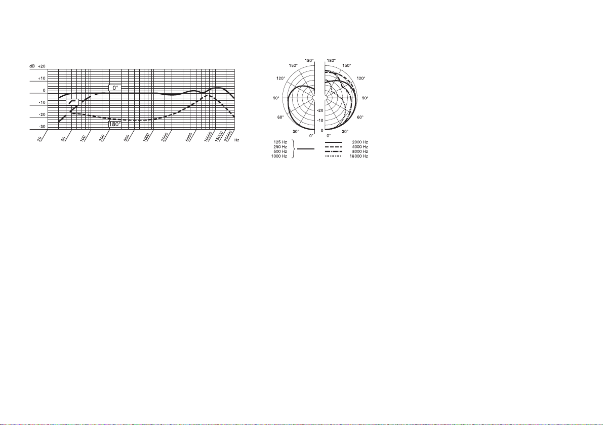
Frequenzkurve Polardiagramm
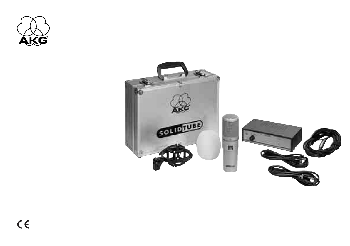
Mitgeliefertes Zubehör: Empfohlenes Zubehör:
N-SOLIDTUBE, Netzgerät PF 80, Studio Popschutzfilter
MK-SOLID, 10 m Anschlußkabel St 102 A, Bodenstativ
H-SOLID, Elastische Halterung St 200, Bodenstativ
W-SOLID, Schaumstoffwindschutz
EUR-Netzkabel
US-Netzkabel
Stabiler Transportkoffer
Page 7
1. The Microphone
The SOLIDTUBE was developed because of the great demand for
the so-called “tube sound” in a price range suitable for many people,
to which it goes without saying that our special know-how in the production of large-diaphragm microphones has had its influence.
It should be stressed at this point that the vacuum tube used with its
inbuilt heater element is significantly more sensitive to mechanical
shocks than is transistor technology. Therefore, the user of this
microphone should always exercise the greatest care and attention.
Even shocks caused by falls from low levels can lead to the breaking
of the hot heating element and, consequently, to the total failure of
the microphone. It is advisable, therefore, to buy and keep in reserve
a spare tube which you can get in any good music shop which sells,
for example, guitar amplifiers, or in the next AKG Service Center.
The microphone incorporates an ECC 83 (12AX7) vacuum tube. Be sure to use replacement tubes of the same type only.
IMPORTANT SAFETY INSTRUCTIONS
Please read, follow and keep these instructions for later consultations. Please heed all warnings for your own safety!
Do not block any ventilation openings on the power supply
unit and do not install the unit near any heat sources such as
radiators, heat registers, stoves, or other apparatus (including amplifiers) that produce heat!
Do not use this device near water!
Clean the power supply unit from time to time with a damp
cloth only!
Do not defeat the safety purpose of the grounding type plug on
the power cord! A grounding type plug has two blades and a
third grounding prong. This third prong is provided for safety.
When the provided plug does not fit into your power outlet,
consult an electrician for replacement of the obsolete outlet.
Should another type of power plug be usual in a country in
which the unit is to be operated then you should buy and use
in that country a complete power cord which complies with
the international safety regulations and which has a plug with
device grounding!
Protect the power cord from being walked on or pinched particularly at plugs and convenience receptacles.
Use only attachment/accessories specified by the manufacturer!
Unplug this apparatus during lighting storms or when unused
for long periods of time!
Refer all servicing to qualified service personnel. Servicing is
required when the apparatus has been damaged in any way,
such as power-supply cord or plug is damaged, liquid has
been spilled or objects have fallen into the apparatus, the apparatus has been exposed to rain or moisture, does not operate normally, or has been dropped.
CAUTION: RISK OF FIRE!
Should the fuse in the power supply unit ever be damaged,
replace with the same Type "T 0.125A, 250V" fuse!
7
Page 8

How is the tube replaced?
IMPORTANT: Prior to disassembling the microphone, make sure
to disconnect the microphone from the N 12 VR power supply.
Remove the three Philips head screws visible on the underside
(connector side) of the housing and push the lower half of the housing downwards so far from the upper grid cap part until the vacuum
tube is exposed. This can now be removed by carefully pushing
away the lower part of the elasticated cushioning for the tube and,
simultaneously, carefully levering the tube out of the socket with a
small flat screwdriver.
Inserting a new tube is done in reverse order of the above description.
Finally, please push the lower part of the housing forwards again to
the grid part and, while doing so, take care that the attenuator
switch remains free so that the three Philips head screws can be
screwed in again fully and tightly.
If you should have doubts as to whether you can carry out
the procedure described above without help then consult
with confidence the nearest AKG Service Center.
How is the microphone mounted?
A special elastic shockmount – “H-Solid” is supplied and
should always be used to connect the microphone to floor stands
or booms. The clamp of the shockmount is pushed on to the microphone from below while turning gently until the SOLIDTUBE type
block can be seen again below the clamp. This makes it impossible
for the microphone to slide out of the mounting unintentionally because this is prevented, on the one side, by the raised type block
and, on the other side, by the grid cap with its larger external diameter. Intentional removal of the microphone from the shockmount is
then only possible by simultaneously turning and pulling the microphone body away from the shockmount.
After fitting the microphone into the shockmount, it can be screwed
on to stands or booms with standard
3
/8or 5/8inch threaded
connections. It may also be swivelled against the stand axis in order
to position the microphone optimally for recording.
Only in exceptional cases – for example, on loss or breakage of parts
of the elastic shockmount – should the microphone be screwed on to
stands or booms directly with the screw adapter on the lower part of
the housing. By doing this, the impact sound absorbing effect of the
shockmount is, naturally, lost. Therefore, replacement of this important accessory part should be obtained as quickly as possible.
Powering the microphone:
The “N-SOLIDTUBE” power supply unit needed for the powering
is included in the delivery. From the type of connector and the markings on the rear of the power supply unit housing, it is easy to see
how the microphone should be connected to the power supply. For
this, please use only the 10 m (30 ft.) long multi-core cable
“MK-SOLID” which is likewise included in the delivery. The audio
can likewise be taken balanced from the power supply unit by
means of an XLR-3 connector.
On the operation of the microphone:
The SOLIDTUBE is equipped with a large diaphragm capsule with
cardioid characteristics which can thus handle nearly all tasks occurring in recording studios.
Although the microphone is provided with an built-in pop screen, an
adequate distance to the microphone of at least 20 to 30 cm (approx. 1 ft.) should be maintained, or the “W-SOLID” wind/pop
screen supplied should be used in order to prevent unwanted
popping noises on the sensitive microphone diaphragm, especially
when using the microphone for singing.
Another way to prevent popping noises is by using the Studio-
Popfilter PF 80 which can be obtained as an option from AKG.
After switching on the microphone power on the power supply unit,
8
Page 9

9
please allow a few minutes for the tube to warm up so as to get the
full, warm “tube sound”.
If the microphone should be used with extremely loud sources of
sound e.g. in front of guitar amplifier speakers etc., then it is advisable to push the attenuation switch on the microphone housing
downwards to the –20 dB position. With this you can be certain that
any distortions do not come from the microphone but either from
the sound source itself or from the equipment connected after the
microphone such as, for example, input stages of mixing consoles
or other causes.
2. The N-SOLIDTUBE Power Supply Unit
SAFETY INSTRUCTIONS: Use the equipment in dry rooms only.
Do not expose the equipment to rain or splash water. Never place
objects containing liquids (e.g., vases) on or near the equipment.
The power supply unit does not only supply the vacuum tube with
heater and anode voltage but also contains the switchable bass cut
for the microphone at about 100 Hz in order to be able to filter out
possible low frequency interference noise components. The control
knob for this is found on the front of the power supply.
For any external wiring, do not use any cables other than those recommended in this manual.
PLEASE OBSERVE CLOSELY!
Dangerous voltages occur in the N-SOLIDTUBE. Opening the
mains unit must definitely, therefore, be done only by qualified
service personnel. WARNING: Parts inside the equipment
may carry dangerous voltages. Make sure to disconnect the
equipment from power before opening the equipment!
Before starting-up the power supply unit please satisfy yourself
about the local mains voltage and compare this with the value set
on the unit’s voltage selector (next to the power switch). If a change-
over of the accepted operating voltage should be necessary then
this can be done very easily with a small flat-bladed screwdriver.
Before doing this, please remove the
mains connection cable from the
mains supply!
Place the screwdriver in the notch provided for this on the fuse holder, press the spring-loaded tongue gently to the right in the direction
of the voltage indicator and lever the whole fuse holder out of the
socket. Then, please pull the light plastic part with the fuse out of
the carrier part, turn the fuse link through 180º and insert it again in
the carrier part until it engages. The desired mains voltage should
now appear in the window. The complete carrier part can then be
inserted into the socket again until this also engages.
You can also proceed in exactly the same way should the unit fuse
ever be damaged.
WARNING: Make sure to replace the built-in fuse with a standard
fuse of the same type only. Using any other type of fuse may cause
excessive heating and/or a risk of fire.
Should another type of power plug be usual in a country in which
the unit is to be operated then you should buy and use in that country a complete power cable which complies with the international
safety regulations and which has a plug with device grounding.
Prior to connecting the equipment to power, check that the power
outlet is a standard type with a protective ground connection. Disconnecting the protective ground lead or using non-standard power plugs or non-standard power outlets is illegal.
If all the above checking steps have been completed, the connecting
cable has been plugged in between the microphone and the power
supply, the audio connection to the after-connected equipment has
been made with standard audio cable, and the plugged-in power cable
Page 10

has been connected to a power socket, then both the control light on
the front of the power supply should light up after switching on the
power supply unit mains switch and also the tube’s heating element
should glow red-orange through the window (AKG logo) on the microphone itself. With this the microphone is essentially ready for operation.
Note: A gentle humming noise can sometimes occur on the audio
output due to ground loops which, as an initial remedy, can possibly
be removed with the “Ground Lift” switch by the audio output
socket on the power supply. When pressed, this switch interrupts
3. Technical Specifications
Operating principle: Large diaphragm pressure gradient microphone with vacuum tube preamplifier
Directional characteristics: Cardioid
Sensitivity at 1000 Hz: 20 mV / Pa Ⳏ –34 dBV re. 1 V / Pa
Frequency range: 20–20,000 Hz ± 2.5 dB from published curve
Electrical impedance: 200 ohms ± 25%
Recommended load impedance: 1000 ohms
Pre-attenuation: Switchable to 0 dB and –20 dB
Bass cut: At 100 Hz 12 dB / octave, can be switched-on on the mains unit
Equivalent noise level conforming to DIN 45405 (CCIR 468-2): 30 dB
Equivalent noise level conforming to DIN 45412 (A-weighted): 20 dB-A
Signal-to-noise ratio ref. 1 Pa (A-weighted): 74 dB
Max. sound pressure for k = 3%: (pre-attenuation 0/–20 dB) 63 Pa Ⳏ 130 dB SPL / 355 Pa Ⳏ 145 dB SPL
Powering: With the delivered N-SOLIDTUBE power supply unit via 115 / 230 VAC,
±15/–10% (50–60 Hz)
Connector: 6 pin XLR
External dimensions: 63/57 Ø x 219 mm (2.5/2.25 Ø x 8.6 inch)
Weight: 920 g (2 lbs.) net
Gross weight incl. packaging: 5.0 kg (11 lbs.) incl. accessories and travelling case
This product conforms to the specifications of the European Union EMC and Low Voltage Directives in accordance with applied
standards EN 61 000-6-1:2001, EN 61 000-3-3:2001, EN 60 065:2002, as well as UL 6500.
10
the connection from pin 1 of the XLR socket to the zero volt /
ground level of the power supply unit.
Should this measure provide no remedy for the interfering hum
then you must locate and remove the cause of the interference
from the rest of the sound system in the usual way.
Cleaning information:
All surfaces can be cleaned from time to time with (industrial) methylated spirits or alcohol. The foam windscreen is best cleaned with a
mild detergent solution and is immediately ready for use when dry.
Page 11

11
Frequency Response Curve Polar Response Curve
Included Accessories: Recommended Accessories:
N-SOLIDTUBE, Power supply unit PF 80, Pop screen filter
MK-SOLID, 10 m (30 ft.) connecting cable St 102 A, Floor stand
H-SOLID, Elastic shockmount St 200, Floor stand
W-SOLID, Foam windscreen
EUR-power cable
US-power cable
Robust carrying case
Page 12

12
1. Le microphone
La demande pour le son dit de “tube” étant importante, on a développé le SOLIDTUBE dans une catégorie de prix accessible à tous
tout en puisant dans notre large expérience en matière de fabrication de microphones à grande membrane.
Dans ce contexte, il ne faut toutefois pas oublier que le tube électronique employé, dans lequel est intégré un élément de chauffage,
est beaucoup plus sensible aux chocs mécaniques que les transistors. Pour cette raison, l’utilisateur de ce microphone devra toujours le manipuler avec précaution et le plus grand soin. Même un
choc reçu lors d’une chute à faible hauteur est susceptible de rompre le filament incandescent et de provoquer une panne totale du
micro. Voilà pourquoi nous vous conseillons de vous procurer un
tube de réserve à titre de précaution auprès d’un magasin de musique spécialisé revendant des amplificateurs pour guitare par exemple ou auprès du point de vente AKG le plus proche.
Le tube électronique utilisé est un tube ECC 83 (12AX7) et ne
peut être remplacé que par un tube de même type.
Comment remplacer le tube électronique?
ATTENTION: N’oubliez jamais de débrancher le microphone du bloc
secteur N 12 VR avant de commencer à démonter le microphone.
Enlevez les trois vis à fentes en croix visibles sur la partie inférieure
(côté prise) du boîtier et poussez la moitié inférieure du boîtier vers le
bas pour l’éloigner du culot de grille supérieur jusqu’à ce que le
tube électronique soit découvert. Pour le retirer, il faut écarter avec
précaution le bas du logement élastique dans lequel il se trouve tout
en soulevant doucement le tube avec un petit tourne-vis plat de
manière à le sortir du socle.
Pour mettre en place le tube neuf, suivez dans le sens inverse les
étapes décrites ci-dessus.
Veuillez ensuite pousser vers l’avant la partie inférieure du boîtier en
direction de la grille tout en veillant à ce que le bouton du modérateur
reste libre, puis revissez et serrez bien les trois vis à fentes en croix.
Si vous pensez ne pas pouvoir effectuer seul les opérations
décrites ci-dessus, n’hésitez pas à vous adresser à votre
point de vente AKG le plus proche.
Comment monter le micro?
On vous a fourni avec votre micro une attache élastique spéciale,
“H-Solid” , qu’il faudra toujours utiliser pour fixer le micro sur un pied
ou une perche. Faites glisser par en bas la bride de fixation de l’attache sur le micro en la tournant légèrement jusqu’à ce que l’inscription SOLIDTUBE soit de nouveau visible sous la bride. De cette ma-
nière, le microphone ne peut pas glisser inopinément hors de l’attache vu que l’inscription en relief d’une part et le culot de grille dont le
diamètre extérieur est plus grand, d’autre part, le retiennent. Pour
sortir le micro de l’attache, on est obligé de tourner le corps du micro
tout en le tirant dans la direction opposée à l’attache.
Après avoir monté le microphone dans l’attache, vous pouvez la
visser sur un pied ou une perche pourvus d’un filet normalisé de
3
/
8
ou 5/8pouces. Il est également possible de faire pivoter l’attache sur
l’axe du pied de façon à trouver l’orientation optimale du micro pour
la prise de son.
On pourra aussi visser directement le microphone sur un pied ou
une perche au moyen du raccord fileté se trouvant sur la partie inférieure du boîtier. Toutefois, on ne recourra à cette solution que
dans des cas exceptionnels, de perte ou de détérioration de certaines pièces de l’attache élastique par exemple, car il est évident
qu’on perd ainsi l’effet de l’attache comme amortisseur du bruit de
structure. Pour cette raison, veillez à remplacer le plus rapidement
possible cet accessoire très important.
Page 13

jusqu’à la position –20 dB. De cette manière, vous pouvez être sûrs
que les distorsions éventuelles ne proviennent pas du micro mais de
la source sonore elle-même ou des appareils situés en aval du micro,
les étages d’entrée des pupitres de mélange par exemple.
2. Le bloc d’alimentation secteur
N-SOLIDTUBE
CONSIGNES DE SÉCURITÉ: Ne peut être utilisé que dans un lo-
cal sec. L’appareil ne doit en aucun cas être exposé aux projections
d’eau ou à de l’eau qui goutte. Ne jamais poser d’objets contenant
un liquide (p.ex. vases) sur l’appareil ou à proximité de celui-ci.
Le bloc d’alimentation secteur ne sert pas seulement à alimenter le
tube électronique en tension de chauffage et en tension anodique,
mais comprend également le dispositif d’atténuation des basses à
100 Hz environ qui permet de filtrer les bruits à basse fréquence
éventuels. A cet effet, le bouton de commande se trouve sur la partie avant du bloc d’alimentation secteur.
Pour les câblages externes, on utilisera exclusivement les câbles
figurant sur la liste des accessoires donnée dans le présent mode
d’emploi.
ATTENTION !!!
Il existe des tensions dangereuses à l’intérieur du N-SOLIDTUBE. Pour cette raison, laissez les techniciens d’entretien
qualifiés se charger de l’ouverture du bloc d’alimentation.
ATTENTION: La tension à l’intérieur de cet appareil peut être
dangereuse. Ne jamais oublier de le débrancher du secteur
avant de l’ouvrir!
Avant la mise en service du bloc d’alimentation secteur, veuil-
lez vérifier quelle tension de réseau est habituelle dans votre région
13
Alimentation électrique du microphone:
Le bloc-secteur, “N-SOLIDTUBE” , nécesaire à l’alimentation du
micro est fourni avec l’appareil. Les types de fiches et les repères se
trouvant sur l’envers du boîtier du bloc d’alimentation permettent de
comprendre facilement la façon dont le microphone doit être raccordé au bloc d’alimentation secteur. Pour cela, veuillez vous servir
exclusivement des 10 m de câble multipolaire “MK-SOLID” fournis
avec l’appareil. Une fiche XLR-3 permet également de capter parallèlement la basse fréquence sur le bloc d’alimentation secteur.
Fonctionnement du microphone:
Le SOLIDTUBE est équipé d’une capsule à grande membrane avec
diagramme directionnel cardioïde, qui sera à même de remplir presque toutes les tâches demandées dans un studio de prise de son.
Bien que le micro ait été pourvu d’une boule anti “P” intégrée, nous
vous recommendons, notamment si vous vous en servez comme
micro de chant, soit de garder une distance suffisante d’au moins
20 à 30 cm lorsque vous parlez dans le micro, soit d’utiliser la boule
anti-vent / anti “P” “W-SOLID” coulissante, livrée avec l’appareil,
de manière à éviter les crachements indésirables sur la membrane
sensible du micro.
Une autre possibilité d’éviter les crachements consiste à installer le
filtre anti “P” de studio PF 80 de chez AKG, disponible en option.
Après avoir mis le microphone sous tension sur le bloc d’alimentation, veuillez laisser le tube “chauffer” pendant quelques minutes
pour obtenir ensuite un son “dit de tube” plein et chaud.
Au cas où vous voudriez employer le micro à proximité de sources
sonores extrêmement fortes telles que les hauts-parleurs des amplificateurs d’une guitare par exemple, nous vous recommendons de
faire glisser vers le bas l’atténuateur placé sur le boîtier du micro, ce
Page 14

14
et la comparer à la valeur réglée sur le sélecteur de tension de l’appareil (à côté de l’interrupteur secteur). Aidez-vous tout simplement
d’un petit tournevis plat pour régler la tension de service acceptée
au cas où cela s’avèrerait nécessaire.
Placez le tournevis dans l’encoche du porte-fusible prévue à cet effet, poussez légèrement vers la droite la languette élastique en direction de l’affichage de tension tout en soulevant la totalité de la
fixation pour fusible hors du socle. Veuillez ensuite tirer sur la partie
en matière plastique claire pour la sortir du porte-fusible en même
temps que le fusible, tournez la cartouche de fusible de 180° et replacez la dans le porte-fusible jusqu’à ce qu’elle prenne l’encoche.
La tension de réseau souhaitée devrait alors apparaître dans la
fenêtre. Vous pouvez maintenant replacer le porte-fusible entier
dans le socle jusqu’à ce que lui aussi prenne l’encoche.
Vous procéderez exactement de la même manière pour remplacer
un fusible endommagé.
AVERTISSEMENT: Le fusible d’origine ne peut être remplacé
que par un fusible aux normes de même type. La non-observation
de cette règle peut entraîner un échauffement excessif avec
risque d’incendie.
Si la fiche secteur ne correspond pas au type courant dans le pays
d’utilisation, il faudra vous y procurer et utiliser un câble d’alimentation secteur complet conforme aux règles de sécurite internationales ainsi qu’une fiche avec mise à la terre de l’appareil.
Cet appareil devra être branché exclusivement sur une prise secteur aux normes, avec terre de protection. Toute interruption de la
terre de même que le montage d’une fiche non conforme aux normes sont proscrits.
Si vous avez effectué toutes les opérations de contrôle mentionnées ci-dessus, branché le câble de jonction entre le microphone et le bloc d’alimentation, utilisé un câble audio normalisé
pour procéder au branchement B.F. sur l’appareil installé en aval et
branché sur une prise de courant le câble d’alimentation secteur
connecté, le voyant témoin situé sur l’avant du bloc d’alimentation
devrait être allumé et le chauffage du tube luire d’une couleur rougeorange visible à travers la fenêtre (logo AKG) sur le micro lui-même,
une fois que vous avez actionné l’interrupteur secteur du bloc d’alimentation. On peut dire que votre microphone est maintenant prêt
à l’emploi.
Remarque: Il se peut parfois que le circuit de retour par la terre provoque un léger ronflement à la hauteur de la sortie B.F., qu’on
pourra éventuellement faire disparaître en actionnant la touche
“Ground Lift” située à côté de la douille de sortie B.F. du bloc d’alimentation. Lorsqu’elle est enfoncée, cette touche interrompt la
connexion entre le doigt 1 de la douille XLR et le niveau zéro volt /
mise à la masse du bloc d’alimentation.
Au cas où cette mesure ne permettrait pas de mettre fin au ronflement perturbant, il vous faudrait en localiser la cause dans le reste
de l’installation de sonorisation et y remédier en procédant de façon
habituelle.
Conseils pour le nettoyage:
De temps en temps, vous pouvez sans problème nettoyer l’intégralité des surfaces avec de l’alcool à brûler (industriel) ou à l’alcool. Le
mieux sera de laver les bonnettes de protection en mousse dans
une solution détergente douce, vous pourrez les réutiliser immédiatement après le séchage.
Auparavant, n’oubliez pas de débran-
cher le câble d’alimention secteur!
Page 15

3. Spécifications techniques
Principe de fonctionnement: microphone à gradient de pression à grande membrane avec préamplificateur
à tubes
Diagramme directionnel: cardioïde
Sensibilité pour 1000 Hz: 20 mV / Pa Ⳏ –34 dBV pour 1 V / Pa
Réponse en fréquence: 20 à 20.000 Hz ± 2,5 dB par rapport à la courbe prescrite
Impédance électrique: 200 ohms ± 25%
Impédance de charge recommandée: 1000 ohms
Préatténuation: réglable sur 0 dB et –20 dB
Atténuation des graves: 12 dB / octave pour 100 Hz, mise en marche sur le bloc d’alimentation
Niveau de bruit équivalent selon DIN 45405 (CCIR 468-2): 30 dB
Niveau de pression acoustique équivalent selon
DIN 45412 (pondération A): 20 dB-A
Rapport signal/bruit pour 1 Pa (pondération A): 74 dB
Pression acoustique maximale pour 3% de distorsion:
(préatténuation 0/–20 dB) 63 Pa Ⳏ 130 dB SPL / 355 Pa Ⳏ 145 dB SPL
Alimentation électrique: avec le bloc d’alimentation secteur N-SOLIDTUBE livré avec l’appareil,
115/230 V alternatif, ±15/–10% (50–60 Hz)
Brochage du connecteur: type XLR hexapolaire
Dimensions exterieures: 63/57 Ø x 219 mm
Poids: 920 g, net
Poids brut, emballage compris: 5.0 kg, accessoires et coffret compris
Ce produit répond aux dispositions des directives européennes pour la sécurité électrique et la compatibilité électromagnétique
selon les normes appliquées NE 61 000-6-1:2001, NE 61 000-3-3:2001, et NE 60 065:2002.
15
Page 16

Courbe de fréquence Diagramme polaire
Accessoires inclus: Accessoires recommandés:
N-SOLIDTUBE, bloc d’alimentation PF 80, filtre anti “P” de studio
MK-SOLID, 10 m de câble de jonction St 102 A, pied
H-SOLID, attache élastique St 200, pied
W-SOLID, bonnettes en mousse
Câble de secteur EUR
Câble de secteur US
Solide coffret pour le transport
16
Page 17

L’installazione di un tubo nuovo verrà effettuata ripetendo gli stessi
passi descritti sopra in successione inversa.
Quindi, spingere nuovamente la parte inferiore del corpo in avanti
verso la grata, avendo cura di lasciare scoperto l’interruttore dell’attenuatore, per poi riavvitare completamente e saldamente le tre viti
con intaglio a croce.
Qualora si avessero dubbi a eseguire il procedimento descritto qui sopra senza aiuti esterni, ci si potrà tranquillamente rivolgere al centro assistenza AKG più vicino.
Come si monta il microfono?
In dotazione è stata fornita una sospensione elastica speciale,
“H-Solid”, che dovrà essere sempre utilizzata per collegare il micro-
fono con supporti da terra o bracci. L’elemento di fissaggio della sospensione va infilato sul microfono dal basso ruotandolo lievemente
in modo tale che la scritta SOLIDTUBE si trovi al di sotto del fis-
saggio stesso. In tal modo si eviterà che il microfono sfugga accidentalmente dalla sospensione grazie sia alla scritta in rilievo sia al maggior diametro esterno del cappuccio a grata. Quando si intenda invece rimuovere il microfono dalla sospensione, occorrerà ruotare e sfilare contemporaneamente il corpo del microfono dalla sospensione.
In seguito all’installazione del microfono nella sospensione, quest’ultima potrà venir avvitata su supporti o bracci con tronchetti filettati standard da
3
/8oppure 5/8pollici. La sospensione potrà venir
girata anche rispetto all’asse del supporto onde orientarla nel modo
migliore per la registrazione.
Solo in casi eccezionali -per esempio in caso di perdita o rottura di
pezzi della sospensione elastica- il microfono potrà venir avvitato direttamente mediante l’adattatore a vite posizionato sulla parte inferiore del corpo a supporti o bracci. L’effetto di attenuazione delle vibrazioni meccaniche prodotto dalla sospensione elastica in questo caso
17
1. Il microfono
Il SOLIDTUBE è stato messo a punto in risposta alla forte do-
manda registrata nei confronti del cosiddetto “tube sound” ad un livello di prezzo accessibile a molti; naturalmente ci siamo avvalsi anche del nostro particolare “know-how” nella produzione di microfoni
a grande membrana.
È necessario menzionare in questa sede che il tubo elettronico
utilizzato con gli elementi scaldanti incorporati è assai più sensibile
ai colpi meccanici rispetto alla tecnologia basata su transistor. Pertanto l’utente di questo microfono dovrà usare sempre la massima
cura e prudenza. Anche colpi causati da cadute da altezze modeste possono comportare la rottura del filamento scaldante e di conseguenza una panne totale del microfono. Per ogni evenienza è
pertanto raccomandabile procurarsi e conservare di riserva un tubo
sostitutivo acquistabile in ogni negozio specializzato in strumenti
musicali di buon livello, come per esempio negozi che trattino amplificatori per chitarre, oppure al più vicino centro assistenza della
AKG.
Il tubo elettronico è un ECC 83 (12AX7) e può essere sostituito solo con un tubo dello stesso tipo.
Come si sostituisce il tubo?
ATTENZIONE: Il microfono deve venir smontato solo quando
prima è stato staccato il collegamento all’alimentatore N 12 VR.
Rimuovere le tre viti con intaglio a croce visibili sul lato inferiore del
corpo (lato dello spinotto) e spingere verso il basso la parte inferiore
dell’involucro dal cappuccio a grata superiore fino a scoprire il tubo
elettronico. A questo punto sarà possibile rimuovere quest’ultimo
premendo e rimuovendo cautamente l’alloggiamento elastico del
tubo e sollevando, facendo leva contemporaneamente con un cacciavite piatto più piccolo, il tubo dallo zoccolo.
Page 18

18
viene naturalmente meno. Sarà pertanto opportuno provvedere
tempestivamente a ripristinare questo fondamentale accessorio.
Alimentazione del microfono:
L’alimentatore ”N-SOLIDTUBE” richiesto per l’alimentazione è
compreso nella fornitura. I modelli di spinotti e i contrassegni apposti sul lato posteriore del corpo dell’alimentatore indicano chiaramente come allacciare il microfono all’alimentatore. A tal fine servirsi
esclusivamente del cavo multipolare di 10 m “MK-SOLID” compreso a sua volta nella fornitura. Anche le basse frequenze potranno
venir captate simmetricamente con l’alimentatore mediante un collegamento XLR-3.
Funzionamento del microfono:
Il SOLIDTUBE è dotato di una capsula a grande membrana con di-
rettività cardioide che sarà in grado di assolvere, pertanto, quasi
tutti i compiti in studio di registrazione.
Sebbene il microfono sia stato dotato di un antipopping, soprattutto
quando lo si impiega per il canto si dovrà rispettare o una distanza
di fonazione di almeno 20–30 cm oppure utilizzare l’antisoffio/antipopping “W-SOLID” in dotazione onde evitare che rumori di popping indesiderati vadano a colpire la membrana del microfono, altamente sensibile.
Un’ulteriore possibilità per evitare rumori da popping consiste nel ricorso al Filtro antipopping da studio PF 80 dell’AKG, un optional
che verrà fornito su richiesta.
In seguito all’inserzione dell’alimentazione del microfono sull’alimentatore lasciare che il tubo “si riscaldi” per qualche minuto: dopo
si avrà il pieno e avvolgente “tube sound”.
Quando si desideri impiegare il microfono presso fonti sonore a vo-
lumi estremi, come per esempio altoparlanti di amplificatori per chitarra, o simili, sarà opportuno spingere verso il basso l’interruttore
dell’attenuatore a –20 dB situato sul corpo del microfono. In tal
modo si avrà la certezza che eventuali distorsioni non saranno originate dal microfono bensì o dalla fonte sonora stessa oppure da apparecchiature inserite a valle del microfono come per esempio stadi
di ingresso di tavoli di missaggio.
2. Alimentatore N-SOLIDTUBE
INDICAZIONI DI SICUREZZA: Solo per ambienti asciutti. L’ap-
parecchio non deve venir esposto all’umidità o all’acqua. Oggetti
contenenti liquidi (p.e. vasi) non devono venir posizionati sull’apparecchio o nelle sue immediate vicinanze).
L’alimentatore non solo alimenta il tubo elettronico con tensione di
riscaldamento ed anodica ma contiene anche l’attenuatore dei
bassi del microfono a -per esempio- 100 Hz, al fine di poter filtrare
ed eliminare rumori di distrurbo a bassa frequenza. Il pulsante di comando si trova sul lato anteriore dell’alimentatore.
Per cablaggi esterni dovranno venir usati solo i cavi raccomandati
nelle presenti istruzioni per l’uso.
OSSERVARE RIGOROSAMENTE!
Nel N-SOLIDTUBE si producono tensioni pericolose. L’apertura dell’alimentatore andrà pertanto lasciata esclusivamente al personale di assistenza qualificato. ATTENZIONE:
In questo apparecchio sono presenti tensioni pericolose.
Prima di aprire l’apparecchio, staccare assolutamente il
connettore dalla presa di rete!
Prima di mettere in esercizio l’alimentatore verificare la tensione
di rete del rispettivo paese paragonandola con il valore preregolato
Page 19

Una volta effettuati tutti i passi di controllo sopra descritti, innestato
il cavo di collegamento tra microfono ed alimentatore, effettuato il
collegamento con l’apparecchio inserito a valle tramite cavi audio
standard e collegato il cavo a rete inserito in una presa a rete, inserendo l’interruttore di rete dell’alimentatore dovrebbe accendersi la
spia di controllo rossa sul lato anteriore dell’alimentatore ed il riscaldamento del tubo, visibile dalla finestrella di controllo (logo AKG),
dovrebbe presentarsi incandescente con una colorazione rossoarancio. A questo punto il microfono sarà fondamentalmente
pronto all’uso.
Avvertenza: Talvolta può verificarsi a causa dei collegamenti di
massa un leggero ronzio sull’uscita delle basse frequenze, che
provvisoriamente potrà venir eliminato con il tasto “ground lift” affianco alla scatola delle uscite delle basse frequenze dell’alimentatore. Questo tasto interrompe, quando è premuto, il collegamento
dal perno 1 della scatola XLR con lo zero-volt / livello massa dell’alimentatore.
Qualora in seguito a tale provvedimento non si dovessero ottenere
risultati contro il ronzio di disturbo, sarà necessario, procedendo
come di consueto, localizzare la causa del disturbo nel resto
dell’impianto acustico ed eliminarla.
Indicazioni per la pulizia:
Tutte le superfici potranno venir pulite di tanto in tanto senza problemi con spirito (industriale) o alcool.
L’antisoffio in schiuma di gomma andrà pulito preferibilmente con
una blanda soluzione detersiva; appena asciugato, l’antisoffio sarà
subito pronto all’uso.
19
sul selettore di tensione dell’alimentatore (affianco all’interruttore di
rete). Se è necessario commutare la tensione d’esercizio preregolata, si potrà farlo molto semplicemente con un cacciavite piatto:
Innestare il cacciavite nell’apposita scanalatura dell’interruttore automatico, premere la linguetta elastica lievemente verso destra in
direzione dell’indicazione di tensione sollevando l’intero alloggiamento del fusibile dal supporto. Quindi estrarre il pezzo in plastica
chiara con il fusibile dal pezzo che funge da supporto, girare l’alloggiamento del fusibile di 180° e rimetterlo nel supporto sino allo
scatto. Il visualizzatore dovrebbe ora mostrare la tensione di rete richiesta. A questo punto l’intero supporto potrà venir rimesso nell’alloggiamento, anche in questo caso sino allo scatto.
Nello stesso modo si dovrà procedere nell’eventualità che il fusibile
dell’apparecchio si danneggi.
AVVERTENZA: Il fusibile integrato dovrà essere sostituito solo
con un fusibile normalizzato dello stesso tipo. Il non rispetto di tale
norma potrà causare surriscaldamento e pericolo di incendio.
Qualora nel paese nel quale si intende mettere in esercizio l’appercchio sia in uso un’altra spina a rete sarà necessario utilizzare un
cavo di collegamento a rete completo conforme alle norme di sicurezza internazionali e dotato di una spina con massa acquistato nel
paese stesso.
Questo apparecchio dovrà essere collegato solo ad una presa di
rete normalizzata, dotata di messa a terra. L’interruzione del collegamento a terra o il montaggio di una presa non conforme alle
norme è vietato.
Innanzitutto staccare il cavo di colle-
gamento dalla rete di alimentazione!
Page 20

3. Dati tecnici
Modo di funzionamento: microfono a grande membrana e gradiente di pressione con preamplificatore a
tubo
Direttività: cardioide
Sensibilità a 1000 Hz: 20 mV / Pa Ⳏ –34 dBV riferito a 1 V / Pa
Risposta in frequenza: 20–20.000 Hz + 2,5 dB rispetto alla curva nominale
Impedenza elettrica: 200 Ohm + 25 %
Impedenza di carico raccomandata: 1000 Ohm
Preattenuazione: commutabile a 0 dB e –20 dB
Attenuazione bassi: a 100 Hz 12 dB / ottava, inseribile sull’alimentatore
Livello del rumore equivalente secondo
DIN 45405 (CCIR 468-2): 30 dB
Livello del rumore equivalente secondo
DIN 45412 (ponderazione A): 20 dB-A
Rapporto segnale/rumore riferito a 1 Pa (ponderazione A): 74 dB
Pressione acustica limite per k = 3 %
(preattenuazione 0/–20 dB): 63 Pa Ⳏ 130 dB SPL / 355 Pa Ⳏ 145 dB SPL
Alimentazione: con l’alimentatore N-SOLIDTUBE compreso nella fornitura a 115/230 VAC,
±15/–10% (50–60 Hz)
Collegamento spina: a 6 poli XLR
Dimensioni esterne: 63/57 Ø x 219 mm
Peso: 920 g, netto
Peso lordo, compresa la confezione: 5,0 kg, compresi accessori e valigetta
Questo prodotto corrisponde alle disposizioni delle direttive europee per la sicurezza in materia di energia elettrica e compatibilità elettromagnetica, secondo le norme d’applicazione EN 61 000-6-1:2001; EN 61 000-3-3:2001, nonché EN 60 065:2002.
20
Page 21

Curva di frequenza Diagramma polare
Accessori in dotazione: Accessori raccomandati:
N-SOLIDTUBE, alimentatore a rete PF 80, filtro antipopping da studio
MK-SOLID, cavo di collegamento di 10 m St 102 A, supporto da terra
H-SOLID, sospensione elastica St 200, supporto da terra
W-SOLID, antisoffio in schiuma di gomma
Cavo di collegamento a rete EUR
Cavo di collegamento a rete US
Valigetta robusta
21
Page 22

1. El micrófono
El SOLIDTUBE ha sido desarrollado debido a la gran demanda del lla-
mado “sonido tubo” dentro de una gama de precios al alcance de todos
los bolsillos, en cuya producción, ni que decir tiene, hemos incorporado
nuestro especial “know-how” de micrófonos de gran membrana.
No podemos dejar de mencionar aquí, que el tubo electrónico utilizado con el filamento calefactor incorporado, es mucho más sensible contra golpes mecánicos que la técnica de transistores. Por
este motivo, el usuario de este micrófono debería actuar con el
mayor cuidado y precaución. Incluso los golpes provocados por la
caída desde poca altura ya pueden causar la rotura del filamento
calefactor, teniendo como consecuencia el fallo total del micrófono.
Por ello se recomienda adquirir en cualquier buena tienda especializada de música, que comercialice p.e. amplificadores de guitarra,
o en el punto de servicio más cercano de AKG, y tener en reserva
un tubo de recambio por si acaso.
La válvula electrónica utilizada es una ECC 83 (12AX7) y sólo
debe ser reemplazada por una válvula del mismo tipo.
¿Cómo se cambia el tubo?
ATENCION: se puede proceder a un desmontaje del micrófono
únicamente si se ha interrumpido primero la conexión con el alimentador de red N 12 VR.
Retirar los tres tornillos estrella en el lado inferior (lado del enchufe)
de la caja y empujar hacia abajo la mitad inferior de la caja de la
parte de capuchón de rejilla superior hasta que el tubo electrónico
esté libre. Ahora se podrá retirar el tubo empujando con cuidado la
parte inferior de suspensión elástica para el tubo y levantando al
mismo tiempo cuidadosamente el tubo del zócalo con un pequeño
destornillador plano.
La colocación de un tubo nuevo se efectúa en sentido inverso al
arriba descrito.
A continuación deslice de nuevo hacia delante la parte inferior de la
caja hacia la parte de rejilla, prestando atención a que el interruptor
del atenuador quede libre, y luego vuelva a apretar completa y firmemente los tres tornillos estrella.
En el caso de duda si es capaz de realizar sin ayuda la operación arriba descrita, diríjase con confianza al punto de servicio de AKG más cercano.
¿Cómo se monta el micrófono?
Se ha incluido un soporte elástico especial “H-Solid”, que debe
emplear siempre para empalmar el micrófono con trípodes o jirafas.
La abrazadera del soporte se desliza desde abajo sobre el micrófono
girando ligeramente hasta que debajo de la abrazadera vuelva a ser
visible la palabra SOLIDTUBE. De este modo será asimismo impo-
sible sacar desintencionadamente el micrófono del soporte, ya que
lo impide por una parte el grabado en relieve, y por otra el mayor diámetro exterior del capuchón de rejilla. La extracción intencionada del
micrófono de su soporte sólo es posible girando y estirando al mismo tiempo el cuerpo del micrófono contra el soporte.
Después de montar el micrófono en el soporte, éste podrá ser enroscado en trípodes o jirafas con tubuladura roscada estándar de
3
/8o 5/8pulgadas. El soporte también podrá girarse enfrente del eje
del trípode, para orientar de forma óptima el micrófono para la grabación.
Sólo en casos excepcionales – por ejemplo en caso de pérdida o
rotura de piezas del soporte elástico – podrá enroscarse el micrófono también directamente al trípode o jirafa con su adaptador roscado que se halla en la parte inferior de la caja. Naturalmente, en
este caso se pierde el efecto de insonorización corporal del so-
22
Page 23

23
porte. Por este motivo debe agenciarse lo antes posible un recambio de este importante accesorio.
Alimentación del micrófono:
El grupo de alimentación “N-SOLIDTUBE” requerido para la alimentación está incluido en el volumen de suministro. Por los tipos
de clavija y marcas en la parte posterior de la caja se reconoce fácilmente la forma de conectar el micrófono en el grupo de alimentación. Para ello utilice exclusivamente el cable multipolar
“MK-SOLID” de 10 m. de largo que asimismo está incluido en el
volumen de suministro. También se puede tomar simétricamente la
BF del grupo de alimentación por medio de un conector XLR-3.
Sobre el modo de empleo del
micrófono:
El SOLIDTUBE está equipado con una gran cápsula de membrana
con característica direccional cardioide, que solucionará casi todas
las tareas que puedan presentarse en un estudio de grabación.
Si bien todos los micrófonos han sido dotados de una protección
antirruido, sobre todo al utilizar el micrófono para cantar debería
mantenerse una distancia de grabación suficiente de entre 20 y 30
cm como mínimo, o utilizarse la pantalla insertable antiviento/antirruido “W-SOLID” que se acompaña para evitar ruidos no desea-
dos en la sensible membrana del micrófono.
Existe otra posibilidad para evitar ruidos por medio del empleo del
Filtro antirruido de estudio PF 80 de AKG disponible como op-
ción.
Después de conectar la alimentación del micrófono en el grupo de
alimentación deje que el tubo se “caliente” durante unos minutos
para lograr después el pleno y cálido “sonido de tubo”.
Si desea utilizar el micrófono en fuentes sonoras extremadamente
potentes, como p.e. delante de altavoces de amplificadores de guitarra o similares, se recomienda deslizar hacia abajo a la posición
–20 dB el variador atenuador que se halla alojado en la caja del
micrófono. De este modo podrá estar seguro de que eventuales
distorsiones no proceden del micrófono, sino o bien de la propia fuente sonora o de los aparatos conectados a continuación al micrófono, como p.e. entradas de pupitres mezcladores o similares.
2. El grupo de alimentación
N-SOLIDTUBE
INSTRUCCIONES DE SEGURIDAD usar sólo en lugares secos.
El aparato no debe quedar expuesto a goteras o salpicaduras de
agua. Objetos que contienen agua (como p.ej. floreros) no deben
colocarse encima de este aparato ni en su cercanía inmediata.
El grupo de alimentación no sólo abastece el tubo electrónico de
tensión calefactora y anódica, sino que contiene también la atenuación de bajos del micrófono a unos 100 Hz, para poder filtrar eventuales elementos de ruidos de frecuencia profunda. El correspondiente botón de mando se encuentra en el lado frontal del grupo de
alimentación.
Para el cableado externo deben utilizarse únicamente los cables
recomendados en este Manual.
¡A OBSERVAR SIN FALTA!
En el N-SOLIDTUBE existen tensiones peligrosas. Por este
motivo es indispensable reservar la apertura del aparato a
personal de servicio cualificado. CUIDADO: en este aparato
se producen tensiones peligrosas. ¡Antes de abrirlo es imprescindible retirar la clavija del enchufe!
Page 24

24
Antes de la puesta en marcha del aparato cerciórese de la tensión de la red local y compárela con el valor programado en el selector de tensión del aparato (junto al interruptor de la red). Cuando
sea necesario conmutar la tensión de servicio admitida, es muy fácil
hacerlo con un pequeño destornillador plano:
Coloque el destornillador en la muesca provista a ese fin en el portafusibles, apriete ligeramente hacia la derecha la lengüeta elástica
en dirección al indicador de tensión, sacando al mismo tiempo todo
el portafusibles del soporte. Después saque la parte de plástico
claro con el fusible del portafusibles, gire en 180° el conjunto de fusible y colóquelo nuevamente en el portafusibles hasta que se encastre. En la mirilla debe aparecer la tensión deseada . Ahora podrá
volver a colocar la unidad completa en el soporte, hasta que se encastre a su vez.
Del mismo modo podrá proceder si se dañara alguna vez el fusible
del aparato.
ADVERTENCIA: el fusible integrado puede cambiarse únicamente por un fusible normalizado del mismo tipo. La inobservancia de esta prescripción puede llevar a un recalentamiento excesivo y causar peligro de incendio.
Si en un país en el que se vaya utilizar el aparato, el enchufe de red
eléctrica fuese distinto, es preciso adquirir y utilizar en ese país un
cable adecuado a la red completo que cumpla las normas internacionales de seguridad y que disponga de un enchufe con toma de
tierra.
Este aparato puede conectarse únicamente con un tomacorriente
de red normalizado equipado con toma protectora de tierra.
Queda prohibido interrumpir el conductor protector o montar un
enchufe no normalizado.
Una vez realizados todos los pasos de comprobación anteriores,
conectado el cable de unión entre el micrófono y el grupo de alimentación y establecida la conexión de BF con el aparato por medio del cable audio estándar y conectado el cable a una base de
red, al conectar el enchufe de red en el grupo de alimentación debe
iluminarse el piloto de control en el lado frontal del grupo de alimentación así como, en el propio micrófono, a través de la mirilla
(Logotipo AKG) lucir el filamento del tubo en rojo-naranja. De este
modo su micrófono estará esencialmente listo para el uso.
A tener en cuenta: A veces puede aparecer un ligero zumbido en
la salida de BF a causa de bucles de tierra, que eventualmente pueden eliminarse como primera medida con la tecla “Ground Lift”
junto a la caja de salida de BF en el grupo de alimentación. Esta
tecla, cuando está pulsada, interrumpe la unión del pin 1 de la caja
XLR con el cero voltios / nivel de masa del grupo de alimentación.
Si esta medida no diera resultado para eliminar el zumbido mezclado, deberá localizar de la forma acostumbrada la causa de la anomalía en el resto del equipo de sonido y eliminarla.
Instrucciones para la limpieza:
Todas las superficies pueden limpiarse de vez en cuando sin problemas, con alcohol industrial o alcohol doméstico. La pantalla antiviento de gomaespuma se limpia preferentemente con una solución suave de detergente y estará inmediatamente lista para su uso
una vez se haya secado.
¡Antes separe el cable de red de la
alimentación de red!
Page 25

3. Datos técnicos
Modo de funcionamiento: Micrófono de gran membrana y gradiente de presión con preamplificador de
tubos
Característica direccional: Cardioide
Sensibilidad a 1000 Hz: 20 mV Pa Ⳏ –34 dBV ref. A 1V/pa
Campo de transmisión: 20–20.000 Hz ± 2,5 dB de curva teórica
Impedancia eléctrica: 200 ohmios ± 25%
Impedancia de carga recomendada: 1000 ohmios
Preatenuación: conmutable a 0 dB y –20 dB
Atenuación de bajos: a 100 Hz 12 dB / octava conmutable en el el grupo de alimentación
Nivel de ruido de recambio según DIN 45405 (CCIR 468-2): 30 dB
Nivel de presión sonora
equivalente según DIN 45412 (apto para audio): 20 dB-A
Distancia de nivel de ruido referida a 1 Pa (apto para audio): 74 dB
Presión sonora máxima para k=3%: (Preatenuación 0/-20 dB) 63 Pa Ⳏ 130 dB SPL/355Pa Ⳏ 145 dB SPL
Alimentación: Mediante el grupo de alimentación N-SOLIDTUBE incluido en el suministro;
115 / 230 VAC, ±15/–10% (50–60 Hz)
Conexión: XLR de 6 terminales
Dimensiones externas: 63/57 Ø x 219 mm
Peso: 920 g, neto
Peso bruto incl. embalaje: 5,0 kg incl. accesorios y maletín
Este producto corresponde a las disposiciones de las directivas europeas para seguridad eléctrica y compatibilidad electromagnética según las normas EN 61 000-6-1:2001, EN 61 000-3-3:2001 y EN 60 065:2002.
25
Page 26

Curva de frecuencia Diagramas polares
Accesorios incluidos: Accesorios recomendados:
N-SOLIDTUBE, grupo de alimentación PF 80, Filtro antirruido de estudio
MK-SOLID, 10 m de cable de conexión St 102 A, trípode
H-SOLID, soporte elástico St 200, trípode
W-SOLID, pantalla antiviento de gomaespuma
Cable de red EUR
Cable de red US
Robusto maletín de transporte
26
Page 27

A recolocação de uma nova válvula processa-se de modo inverso
ao acima descrito.
De seguida, desloque para cima, em direcção à tampa de rede, a
parte inferior da carcaça, tendo em atenção que o interruptor de
atenuação fique liberto, para então aparafusar totalmente os três
parafusos de fenda em cruz.
Caso tenha dúvidas para executar o procedimento acima
descrito, dirija-se com confiança ao serviço de assistência
AKG mais próximo.
Modo de montar o microfone
Conjuntamente é fornecido um suporte especial elástico
“H-Solid” e deverá ser sempre utilizado para ligar o microfone aos
suportes de pé ou braços de prolongamento. O grampo do suporte
é encaixado no microfone de baixo para cima, rodando ligeiramente
até que apareçam os dizeres SOLIDTUBE novamente por baixo do
grampo de suporte. Com isso é evitado um deslizar inadvertido do
suporte por parte do microfone, dado que por um lado os dizeres em
relevo e pelo outro o diâmetro superior da tampa de rede o evitam. O
retirar intencional do microfone do suporte, só é possível rodando e
desencaixando ao mesmo tempo o microfone de suporte.
Após ter montado o microfone no suporte este poderá ser aparafusado em suportes de pé ou em braços de prolongamento com
pontas roscadas de
3
/8ou 5/8de polegadas. O suporte poderá oscilar em relação ao eixo do suporte de pé para o direccionar de
forma optimizada para a gravação.
Só em casos excepcionais – por ex. em caso de perda ou quebra
das pares elásticas do suporte – poderá ser aparafusado o microfone também directamente com o adaptador roscado, situado na
parte inferior da carcaça, em suportes de pé ou em braços de pro-
27
1. O microfone
A SOLIDTUBE foi concebida devido à grande procura para o as-
sim chamado “som de válvula” dentro de um preço acessível para
muitos, com a natural introdução do nosso “know-how” de produção de microfones de membranas de grande área.
Não queremos deixar passar despercebido, que a válvula electrónica, utilizada com o seu filamento de aquecimento é muito mais
sensível a choques mecânicos que a técnica transistorizada. Devido a isso, o utilizador, ao manusear este microfone, deverá ter o
máximo de cuidado e atenção. Mesmo pancadas resultantes de
embates de pequena altura, poderão provocar a quebra do filamento quente e provocar a falha total do microfone. Por essa razão, é recomendável adquirir para todos os casos, uma válvula e
tê-la de reserva, por exemplo, numa boa loja de aparelhos musicais
que vendam, por exemplo, amplificadores de guitarras ou no serviço de assistência AKG mais próximo.
O microfone utiliza uma válvula do tipo ECC 83 (12AX7). Use
sómente válvulas de reposição do mesmo tipo.
Modo de substituição da válvula
CUIDADO: o microfone só poderá ser desmontado, se interrom-
per antes a conexão ao adaptador de força N 12 VR.
Retirar os três parafusos de fenda em cruz, visíveis na parte inferior
(lado da ficha), da carcaça e deslocar para baixo a parte inferior da
carcaça da parte superior da tampa de rede, até que a válvula electrónica se encontre acessível. Então será possível retirá-la, ao deslocar para o lado, com cuidado, a parte elástica do suporte e ao
mesmo tempo auxiliado com uma pequena chave de fendas chata,
levantando a válvula do seu suporte.
Page 28

28
longamento. Perde-se contudo, com isso, o efeito de atenuação
do som corporal do suporte. Deve-se portanto tratar rapidamente
da substituição deste importante acessório.
Alimentação do microfone:
Alimentador “N-SOLIDTUBE” necessário para a alimentação, faz
parte do fornecimento. É facilmente reconhecível pelo tipo de
fichas e marcações existentes nas costas do alimentador, como se
deve ligar o microfone ao alimentador. Para o efeito, utilize exclusi-
vamente o cabo múltiplo de 10 m de comprimento “MK-SOLID”
também juntamente fornecido. A NF também pode ser extraída simetricamente através de uma ficha de ligação XLR-3.
Para o funcionamento do microfone
O SOLIDTUBE é equipado com uma cápsula de membrana de
grande dimensão, com uma característica direccional em forma de
rim, que assim resolverá quase todas as situações que possam
surgir num estúdio de gravação.
Mesmo que o microfone esteja equipado com uma protecção antipop, deverá ser respeitada uma distância de voz de pelo memos
20 a 30 cm, em especial ante a utilização de microfone de canto, ou
utilizar o protector de vento / anti-pop “W-SOLID”, também fornecido para evitar ruídos de “pop”, não desejados na membrana
sensível do microfone.
Outra possibilidade para evitar os ruídos “pop”, consiste na utilização de um filtro de estúdio pop PF 80 da AKG, como opção e
que pode ser adquirido.
Após ligar a alimentação do microfone no alimentador de corrente,
aguarde por favor, alguns minutos para “aquecimento” da válvula
para em seguida obter o suave “som de válvula”.
Se desejar utilizar o microfone frente a fontes sonoras extremamente altas, como por ex. frente a altifalantes de amplificadores de
guitarras, ou semelhantes, é aconselhável deslocar para baixo o interruptor de atenuação instalado no microfone, para a posição
–20 dB. Deste modo assegura-se que eventuais distorções não
provêm do microfone, mas, ou da fonte sonora em si ou da aparelhagem ligada posteriormente ao microfone, como por ex. amplificadores de entrada de mesas de mistura ou semelhantes.
2. O alimantador N - SOLIDTUBE
AVISOS DE SEGURANÇA: O aparelho é concebido apenas
para ambientes secos. O aparelho não deverá ser exposto a gotas de água ou a lugares onde há sistemas de pulverização de
água. Não coloque objetos que contenham líquidos (como por
exemplo, vasos de flores) em cima ou perto do aparelho.
O alimentador não só alimenta a válvula electrónica coma tensão
para o filamento de aquecimento e a tensão anódica, como também, compreende o atenuamento dos grave no microfone, nos
100 Hz aproximadamente, para poder filtrar eventuais componentes de perturbação de baixa frequência. O botão de accionamento
para o efeito, situa-se na parte frontal do alimentador.
Para a cablagem externa, poderá utilizar apenas os cabos opcionais recomendados neste manual.
PRESTE ESPECIAL ATENÇÃO
No N-SOLIDTUBE geram-se tensões perigosas. Daí que o
alimentador só deva ser aberto por pessoal de serviço qualificado. CUIDADO: neste aparelho há voltagens perigosas.
Antes de abrir o aparelho, é absolutamente necessário tirar
o plugue da tomada!
Page 29

29
Antes de colocar o alimentador em funcionamento certifiquese, por favor, da tensão eléctrica utilizada localmente e compare-a
com o valor regulado no aparelho (ao lado do interruptor de corrente). Se for necessária uma comutação da tensão de funcionamento, será fácil realizá-la com a ajuda de uma pequena chave
de fendas.
Coloque a chave de fendas na ranhura do suporte de fusíveis
previsto para o efeito, pressione ligeiramente o linguete elástico
para a direita, em direcção à indicação da tensão e desloque o suporte de fusíveis completo para o exterior do encaixe. De seguida,
puxe a peça de plástico clara, com o fusível do suporte, rode-o em
180º e coloque-o de novo até encaixar. Agora, poderá colocar o
suporte completo novamente no encaixe, até que ele também encaixe.
Proceda da mesma forma se alguma vez o fusível do aparelho se
avariar.
AVISO: O fusível integrado poderá ser substituído apenas por um
fusível de norma do mesmo tipo. Caso não seja respeitada esta
recomendação, o aparelho poderá aquecer-se, provocando perigo de incêndio.
Caso seja usual um outro tipo de ficha de corrente, no país onde o
aparelho vai ser utilizado, deverá então adquirir um cabo completo
que corresponda às normas de segurança internacionais e que
possua uma ficha com ligação à terra.
Este aparelho deverá ser ligado apenas a uma tomada de norma
provida duma ligação à terra. É proibido interromper o condutor
de proteção e fixar um plugue que não corresponda às normas.
Após terem sido dados todos os passos anteriores de controlo, ter
sido ligado o cabo de ligação entre o microfone e o alimentador, a ligação de BF para a aparelhagem posterior por intermédio de cabos audio do tipo standard e ter sido ligado o cabo de alimentação
à tomada do sector, deverá acender a lâmpada de controlo no alimentador, após ligação deste através do respectivo interruptor,
bem como no microfone em si, reluzir através do visor (logotipo
AKG) o aquecimento da válvula na cor vermelho-laranja. Deste
modo o microfone estará, no seu essencial, pronto a funcionar.
Para ter em conta: algumas vezes poderá ocorrer um ligeiro zumbido na saída BF derivado a circuitos de retorno à terra e que como
primeira solução poderá ser eliminado com a tecla “Ground LIFT”
junto à saída BF no alimentador. Esta tecla interrompe estando premida, a ligação do pino 1 da tomada XLR para o zero volt / massa
do alimentador.
Caso este procedimento não elimine o zumbido introduzido, então
terá de localizar e eliminar a causa da interferência no resto da aparelhagem sonora, de forma usual.
Indicações para a limpeza:
Todas as superfícies poderão ser limpas de tempo a tempo com álcool desnaturado ou álcool. O protector de espuma anti-vento deverá ser limpo com uma barrela suave de detergente e ser reutilizado, logo que se encontre seco.
Antes disso, retire, por favor, o cabo
de ligação do sector alimentador
Page 30

30
3. Dados técnicos
Tipo de funcionamento: Microfone de gradiente pressurizado – membrana de grande dimensão com
pré-amplificador de válvula
Característica direccional: Rim
Sensibilidade a 1000 Hz: 20mV / Pa Ⳏ –34 dBV ou em 1 V / Pa
Banda passante: 20–20.000 Hz ± 2,5 dB da curva nominal
Impedância eléctrica: 200 Ohm ± 25%
Impedância de carga recomendada: 1000 Ohm
Pré-atenuação: comutável para 0 dB e –20 dB
Atenuação de baixos: em 100 Hz 1 dB / oitava, comutável ao alimentador
Nível de ruído equivalente conforme DIN 45405 (CCIR 468-2): 30 dB
Nível de pressão acústica equivalente conforme DIN 45412
(valor-A): 20 dB-A
Distância do nível de ruído relativo a 1 Pa (valor-A): 74 dB
Limite da pressão acústica para k = 3%:
(Pré-atenuação 0/–20 dB) 63 Pa Ⳏ 130 dB SPL / 355 Pa Ⳏ 145 dB SPL
Alimentação: com o alimentador fornecido N-SOLIDTUBE para 115 /230 VAC,
±15/–10% (50–60 Hz)
Ficha de ligação: 6 pinos XLR
Dimensões exteriores: 63/57 Ø x 219 mm
Peso: 920 gr. líquido
Peso bruto, incl. bagagem 5,0 kg, incl. acessórios e mala de transporte
Este produto corresponde às diretivas européias para a segurança elétrica e compatibilidade eletromagnética conforme as normas aplicadas EN 61 000-6-1:2001, EN 61 000-3-3:2001, e EN 60 065:2002.
Page 31

Curva de frequência Diagrama de polarização
Acessórios fornecidos Acessórios recomendados
N-SOLIDTUBE, alimentador PF 80, Filtro de estúdio anti-pop
MK-SOLID, 10 m de cabo de ligação St 102 A, suporte de pé
H-SOLID, suporte elástico St 200, suporte de pé
W-SOLID, pára-vento com espuma plástica
EUR-cabo eléctrico de alimentação
US-cabo eléctrico de alimentação
Mala de transporte resistente
31
Page 32

Technische Änderungen vorbehalten. Specifications subject to change without notice. Ces caractéristiques sont susceptibles de modifications.
Ci riserviamo il diritto di effettuare modifiche tecniche. Nos reservamos el derecho de introducir modificaciones técnicas. Especificações sujeitas a mudanças sem aviso prévio.
Mikrofone · Kopfhörer · Drahtlosmikrofone · Drahtloskopfhörer · Kopfsprechgarnituren · Akustische Komponenten
Microphones · Headphones · Wireless Microphones · Wireless Headphones · Headsets · Electroacoustical Components
Microphones · Casques HiFi · Microphones sans fil · Casques sans fil · Micros-casques · Composants acoustiques
Microfoni · Cuffie HiFi · Microfoni senza filo · Cuffie senza filo · Cuffie-microfono · Componenti acustici
Micrófonos · Auriculares · Micrófonos inalámbricos · Auriculares inalámbricos · Auriculares con micrófono · Componentes acústicos
Microfones · Fones de ouvido · Microfones s/fios · Fones de ouvido s/fios · Microfones de cabeça · Componentes acústicos
Printed in Austria on recycled paper. 03/03/9100 U 0945
AKG Acoustics GmbH
Lemböckgasse 21–25, P.O.B. 158, A-1230 Vienna/AUSTRIA, Tel: (+43 1) 86 654-0*, Fax: (+43 1) 86 654-7516, www.akg.com, e-mail: sales@akg.com
AKG Acoustics GmbH
Bodenseestraße 228, D-81243 München/GERMANY, Tel: (+49 89) 87 16-0, Fax: (+49 89) 87 16-200, www.akg-acoustics.de, e-mail: info@akg-acoustics.de
AKG ACOUSTICS, U.S.
914 Airpark Center Drive, Nashville, TN 37217, U.S.A., Tel: (+1 615) 620-3800, Fax: (+1 615) 620-3875, www.akgusa.com, e-mail: akgusa@harman.com
For other products and distributors worldwide see our website: www.akg.com
 Loading...