

Page 1
PS 4000 W
+ antenna system
BEDIENUNGSANLEITUNG . . . . . . . . . . . . . S. 2
Bitte vor Inbetriebnahme des Gerätes lesen!
USER INSTRUCTIONS . . . . . . . . . . . . . . . . . . p. 1 1
Please read the manual before using the equipment!
MODE D’EMPLOI . . . . . . . . . . . . . . . . . . . . . . . . p. 20
Veuillez lire cette notice avant d’utiliser le système!
ISTRUZIONI PER L’USO . . . . . . . . . . . . . . . p. 29
Prima di utilizzare l’apparecchio, leggere il manuale!
MODO DE EMPLEO . . . . . . . . . . . . . . . . . . . . .p. 38
¡Sirvase leer el manual antes de utilizar el equipo!
INSTRUÇÕES DE USO . . . . . . . . . . . . . . . . . p. 4 7
Favor leia este manual antes de usar o equipamento!
Page 2
Inhaltsverzeichnis
1 Sicherheit und Umwelt . . . . . . . . . . . . . . . . . . . . . . . . . . . . . . . . . . . . . . . . . . . . . . . . . . . . . . . . . . . . . . . . . . 2
1.1 Sicherheit . . . . . . . . . . . . . . . . . . . . . . . . . . . . . . . . . . . . . . . . . . . . . . . . . . . . . . . . . . . . . . . . . . . . . . . . 2
1.2 Umwelt . . . . . . . . . . . . . . . . . . . . . . . . . . . . . . . . . . . . . . . . . . . . . . . . . . . . . . . . . . . . . . . . . . . . . . . . . . 3
2 Beschreibung . . . . . . . . . . . . . . . . . . . . . . . . . . . . . . . . . . . . . . . . . . . . . . . . . . . . . . . . . . . . . . . . . . . . . . . . . 3
2.1 Einleitung. . . . . . . . . . . . . . . . . . . . . . . . . . . . . . . . . . . . . . . . . . . . . . . . . . . . . . . . . . . . . . . . . . . . . . . . . 3
2.2 Lieferumfang . . . . . . . . . . . . . . . . . . . . . . . . . . . . . . . . . . . . . . . . . . . . . . . . . . . . . . . . . . . . . . . . . . . . . . 3
2.3 Empfohlenes Zubehör. . . . . . . . . . . . . . . . . . . . . . . . . . . . . . . . . . . . . . . . . . . . . . . . . . . . . . . . . . . . . . . . 3
2.4 Beschreibung. . . . . . . . . . . . . . . . . . . . . . . . . . . . . . . . . . . . . . . . . . . . . . . . . . . . . . . . . . . . . . . . . . . . . . 3
2.4.1 Frontplatte . . . . . . . . . . . . . . . . . . . . . . . . . . . . . . . . . . . . . . . . . . . . . . . . . . . . . . . . . . . . . . . . . . . 3
2.4.2 Rückseite . . . . . . . . . . . . . . . . . . . . . . . . . . . . . . . . . . . . . . . . . . . . . . . . . . . . . . . . . . . . . . . . . . . . 4
2.5 Zentrale Stromversorgung PSU 4000 (optional). . . . . . . . . . . . . . . . . . . . . . . . . . . . . . . . . . . . . . . . . . . . . 4
2.6 Empfangsantennen (optional) . . . . . . . . . . . . . . . . . . . . . . . . . . . . . . . . . . . . . . . . . . . . . . . . . . . . . . . . . . 4
2.6.1 SRA 2 B/W . . . . . . . . . . . . . . . . . . . . . . . . . . . . . . . . . . . . . . . . . . . . . . . . . . . . . . . . . . . . . . . . . . . 4
2.6.2 RA 4000 B/W . . . . . . . . . . . . . . . . . . . . . . . . . . . . . . . . . . . . . . . . . . . . . . . . . . . . . . . . . . . . . . . . . 4
3 Inbetriebnahme. . . . . . . . . . . . . . . . . . . . . . . . . . . . . . . . . . . . . . . . . . . . . . . . . . . . . . . . . . . . . . . . . . . . . . . . 5
3.1 Rackmontage eines Antennensplitters . . . . . . . . . . . . . . . . . . . . . . . . . . . . . . . . . . . . . . . . . . . . . . . . . . . . 5
3.2 Rackmontage zweier Antennensplitter nebeneinander . . . . . . . . . . . . . . . . . . . . . . . . . . . . . . . . . . . . . . . . 5
3.3 Antennen aufstellen . . . . . . . . . . . . . . . . . . . . . . . . . . . . . . . . . . . . . . . . . . . . . . . . . . . . . . . . . . . . . . . . . 5
3.3.1 Aufstellungsort . . . . . . . . . . . . . . . . . . . . . . . . . . . . . . . . . . . . . . . . . . . . . . . . . . . . . . . . . . . . . . . . 5
3.3.2 Montage auf Bodenstativ . . . . . . . . . . . . . . . . . . . . . . . . . . . . . . . . . . . . . . . . . . . . . . . . . . . . . . . . . 5
3.3.3 Wand/Deckenmontage . . . . . . . . . . . . . . . . . . . . . . . . . . . . . . . . . . . . . . . . . . . . . . . . . . . . . . . . . . 5
3.4 Antennen anschließen . . . . . . . . . . . . . . . . . . . . . . . . . . . . . . . . . . . . . . . . . . . . . . . . . . . . . . . . . . . . . . . 6
3.4.1 Einkanalanlage mit passiven Antennen . . . . . . . . . . . . . . . . . . . . . . . . . . . . . . . . . . . . . . . . . . . . . . . 6
3.4.2 Einkanalanlage mit aktiven Antennen . . . . . . . . . . . . . . . . . . . . . . . . . . . . . . . . . . . . . . . . . . . . . . . . 6
3.5 Mehrkanalanlagen mit Antennensplitter PS 4000 W . . . . . . . . . . . . . . . . . . . . . . . . . . . . . . . . . . . . . . . . . . 6
3.6 CLA-Schalter . . . . . . . . . . . . . . . . . . . . . . . . . . . . . . . . . . . . . . . . . . . . . . . . . . . . . . . . . . . . . . . . . . . . . . 7
4 Betriebshinweise . . . . . . . . . . . . . . . . . . . . . . . . . . . . . . . . . . . . . . . . . . . . . . . . . . . . . . . . . . . . . . . . . . . . . . 9
4.1 Allgemeine Hinweise . . . . . . . . . . . . . . . . . . . . . . . . . . . . . . . . . . . . . . . . . . . . . . . . . . . . . . . . . . . . . . . . 9
4.2 Anlagen mit dezentraler Stromversorgung . . . . . . . . . . . . . . . . . . . . . . . . . . . . . . . . . . . . . . . . . . . . . . . . . 9
4.2.1 Einschalten . . . . . . . . . . . . . . . . . . . . . . . . . . . . . . . . . . . . . . . . . . . . . . . . . . . . . . . . . . . . . . . . . . . 9
4.2.2 Ausschalten . . . . . . . . . . . . . . . . . . . . . . . . . . . . . . . . . . . . . . . . . . . . . . . . . . . . . . . . . . . . . . . . . . 9
4.3 Anlagen mit optionaler zentraler Stromversorgung PSU 4000 . . . . . . . . . . . . . . . . . . . . . . . . . . . . . . . . . . . 9
4.3.1 Einschalten . . . . . . . . . . . . . . . . . . . . . . . . . . . . . . . . . . . . . . . . . . . . . . . . . . . . . . . . . . . . . . . . . . . 9
4.3.2 Ausschalten . . . . . . . . . . . . . . . . . . . . . . . . . . . . . . . . . . . . . . . . . . . . . . . . . . . . . . . . . . . . . . . . . . 9
!
L
11..11 SSiicchheerrhheeiitt
5 Reinigung . . . . . . . . . . . . . . . . . . . . . . . . . . . . . . . . . . . . . . . . . . . . . . . . . . . . . . . . . . . . . . . . . . . . . . . . . . . . 9
6 Fehlerbehebung . . . . . . . . . . . . . . . . . . . . . . . . . . . . . . . . . . . . . . . . . . . . . . . . . . . . . . . . . . . . . . . . . . . . . . . 9
7 Technische Daten . . . . . . . . . . . . . . . . . . . . . . . . . . . . . . . . . . . . . . . . . . . . . . . . . . . . . . . . . . . . . . . . . . . . . 10
Fig. 8 bis 13 . . . . . . . . . . . . . . . . . . . . . . . . . . . . . . . . . . . . . . . . . . . . . . . . . . . . . . . . . . . . . . . . . . . . . . . . . . . . 56
1 Sicherheit und Umwelt
1. Schütten Sie keine Flüssigkeiten auf das Gerät und lassen Sie keine sonstigen Gegenstände durch die Lüftungsschlitze in das
Gerät fallen.
2. Das Gerät darf nur in trockenen Räumen eingesetzt werden.
3. Das Gerät darf nur von autorisiertem Fachpersonal geöffnet, gewartet und repariert werden. Im Inneren des Gehäuses befinden
sich keinerlei Teile, die vom Laien gewartet, repariert oder ausgetauscht werden können.
4. Prüfen Sie vor Inbetriebnahme des Gerätes, ob die auf dem mitgelieferten Netzgerät angegebene Betriebsspannung der
Netzspannung am Einsatzort entspricht.
5. Betreiben Sie das Gerät ausschließlich mit dem mitgelieferten Netzgerät mit einer Ausgangsspannung von 12 V DC. Andere
Stromarten und Spannungen könnten das Gerät ernsthaft beschädigen!
6. Brechen Sie den Betrieb der Anlage sofort ab, wenn ein fester Gegenstand oder Flüssigkeit in das Geräteinnere gelangen sollte.
Ziehen Sie in diesem Fall sofort das Netzkabel des Netzgeräts aus der Steckdose und lassen Sie das Gerät von unserem
Kundendienst überprüfen.
7. Ziehen Sie das Netzkabel des Netzgeräts bei längerer Nichtverwendung aus der Steckdose. Bitte beachten Sie, dass bei angestecktem Netzgerät das Gerät nicht vollständig vom Netz getrennt wird, wenn Sie es ausschalten.
8. Stellen Sie das Gerät nicht in der Nähe von Wärmequellen wie z. B. Radiatoren, Heizungsrohren, Verstärkern, usw. auf und setzen Sie es nicht direkter Sonneneinstrahlung, starker Staub- und Feuchtigkeitseinwirkung, Regen, Vibrationen oder Schlägen
aus.
9. Verlegen Sie zurVermeidung von Störungen bzw.Einstreuungen sämtlicheLeitungen, spezielldie der Mikrofoneingänge,getrennt
von Starkstromleitungen und Netzleitungen. Bei Verlegung in Schächten oder Kabelkanälen achten Sie darauf, die Übertragungsleitungen in einem separaten Kanal unterzubringen.
10. Reinigen Sie das Gerät nur mit einem feuchten, aber nicht nassenTuch. Ziehen Sie unbedingt das Netzkabel des Netzgeräts vorher aus der Steckdose! Verwenden Sie keinesfalls scharfe oder scheuernde Reinigungsmittel sowie keine, die Alkohol oder
Lösungsmittel enthalten, da diese den Lack sowie die Kunststoffteile beschädigen könnten.
11. Verwenden Sie das Gerät nur für die in dieser Bedienungsanleitung beschriebenen Anwendungen. Für Schäden infolge unsachgemäßer Handhabung oder missbräuchlicher Verwendung kann AKG keine Haftung übernehmen.
2
AKG PS 4000 W
Page 3
1 Sicherheit und Umwelt
!
L
1. Das Netzgerät nimmt auch bei ausgeschaltetem Gerät einen geringen Strom auf. Um Energie zu sparen, ziehen Sie daher das
Netzkabel des Netzgeräts von der Netzsteckdose ab, wenn Sie das Gerät längere Zeit nicht benützen.
2. Wenn Sie das Gerät verschrotten, trennen Sie Gehäuse, Elektronik und Kabel und entsorgen Sie alle Komponenten gemäß den
dafür geltenden Entsorgungsvorschriften.
3. Die Verpackung ist recyclierbar. Entsorgen Sie die Verpackung in einem dafür vorgesehenen Sammelsystem.
2 Beschreibung
Vielen Dank, dass Sie sich für ein Produkt aus dem Hause AKG entschieden haben. Bitte lesen Sie die Bedienungsanleitung aufmerksam durch, bevor Sie das Gerät benützen, und bewahren Sie die Bedienungsanleitung sorgfältig auf, damit Sie jederzeit
nachschlagen können. Wir wünschen Ihnen viel Spaß und Erfolg!
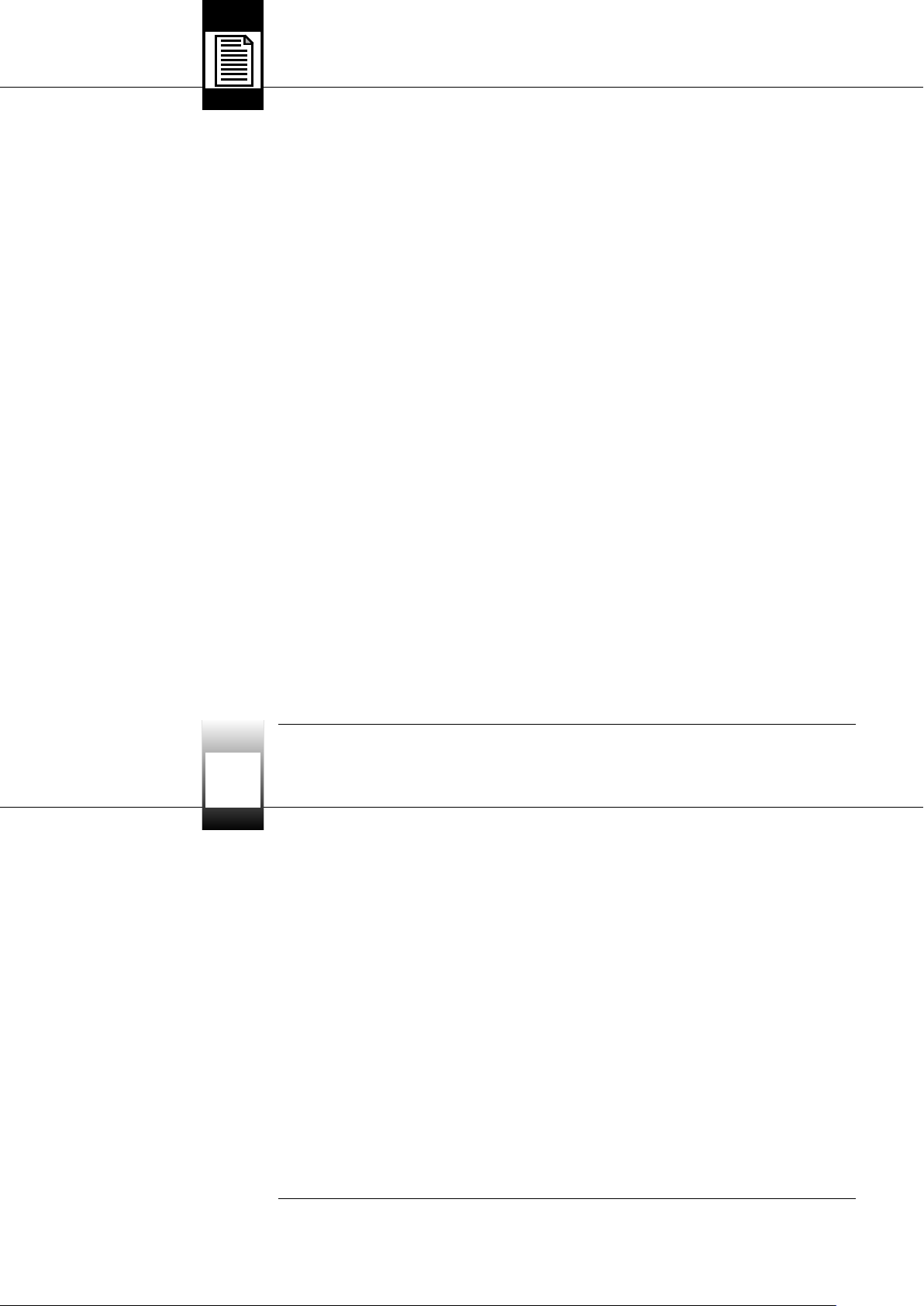
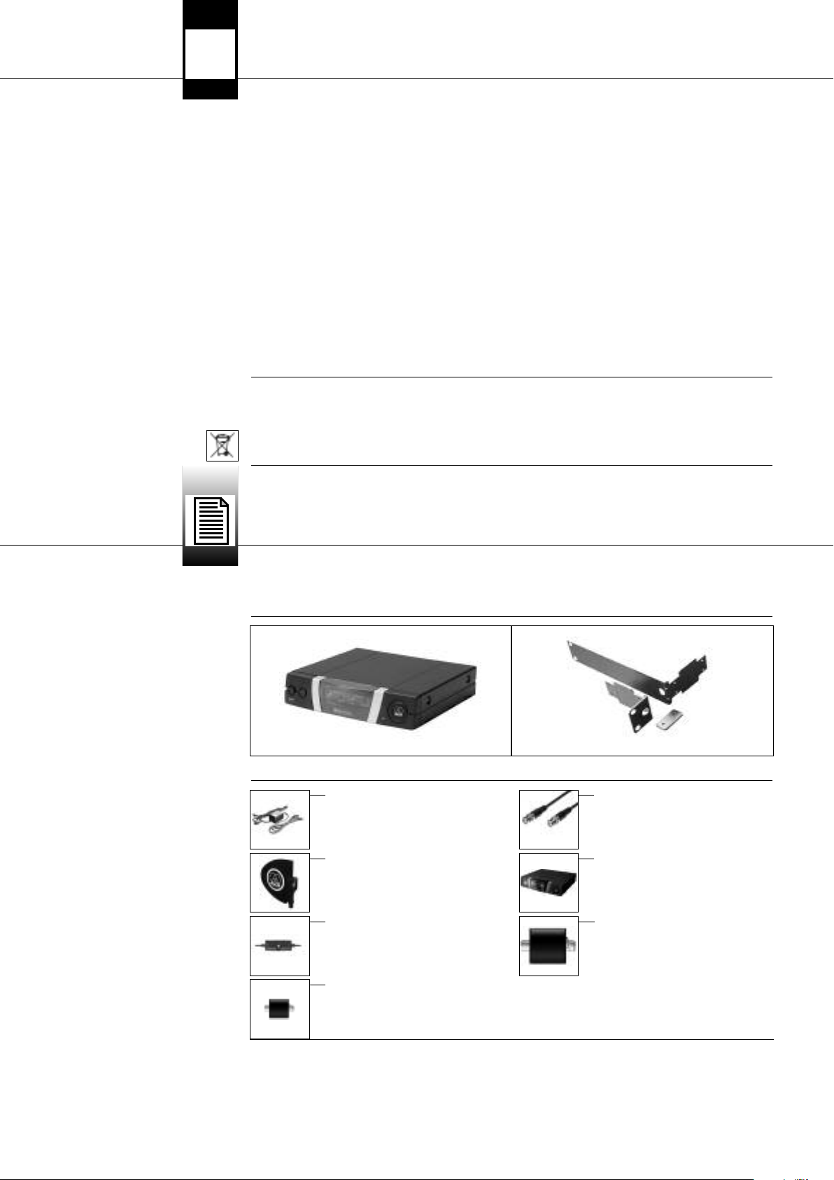
1 Antennensplitter PS 4000 W 1 19"-Montageset
Kontrollieren Sie bitte, ob die Verpackung alle oben angeführten Teile enthält. Falls etwas fehlt, wenden Sie sich bitte an Ihren AKGHändler.
• Netzgerät für 12 V DC
• Antennenkabel MK PS
11..22 UUmmwweelltt
22..11 EEiinnlleeiittuunngg
22..22 LLiieeffeerruummffaanngg
22..33 OOppttiioonnaalleess ZZuubbeehhöörr
• Aktive Richtantenne SRA 2 B/W
• Aktive omnidirektionale Antenne
RA 4000 B/W
• Antennenverstärker AB 4000
Der Antennensplitter PS 4000 W ist ein Antennenverteiler zum Aufbau eines UHF-Mehrkanalsystems mit bis zu vier Empfängern je
Antennensplitter (die tatsächliche Anzahl gleichzeitig betreibbarer Kanäle hängt vom Frequenzplan des Einsatzlandes ab).
Der PS 4000 W besitzt zwei Antennen-Eingangsbuchsen, an die Sie die aktiven Empfangs antennen SRA 2 B/W oder RA 4000 B/W mit
eingebautem Booster (Antennenverstärker) anschließen können. Die Antenneneingänge stellen eine Versorgungsspannung von 12 V
DC für maximal drei aktive Antennenkomponenten, z.B. eine aktive Antenne und zwei Antennenverstärker AB 4000, bereit. An der
Rückseite stehen weiters 2 x 4 Antennen-Ausgangsbuchsen für bis zu 4 Diversity-Empfänger sowie zwei zusätzliche AntennenAusgangsbuchsen zum Weiterleiten des Antennensignals an mehrere zusätzliche Antennensplitter PS 4000 W zur Verfügung.
Der PS 4000 W besitzt ein 1 HE hohes, robustes Metallgehäuse in halber 19”-Breite, so dass Sie zwei Antennensplitter nebeneinander in einer Rackebene montieren können.
Die Stromversorgung des PS 4000 W erfolgt über ein optionales Netzgerät. Für Anlagen mit mehr als 4 Kanälen empfehlen wir die
optionale zentrale Stromversorgung PSU 4000 für je drei Antennensplitter.
Sowohl die Antennenverstärker als auch der Antennensplitter sind Breitbandgeräte für den gesamten UHF-Frequenzbereich.
• Zentrale Stromversorgung
PSU 4000
• Fernspeisegerät
ASU 4000
22..44 BBeesscchhrreeiibbuunngg
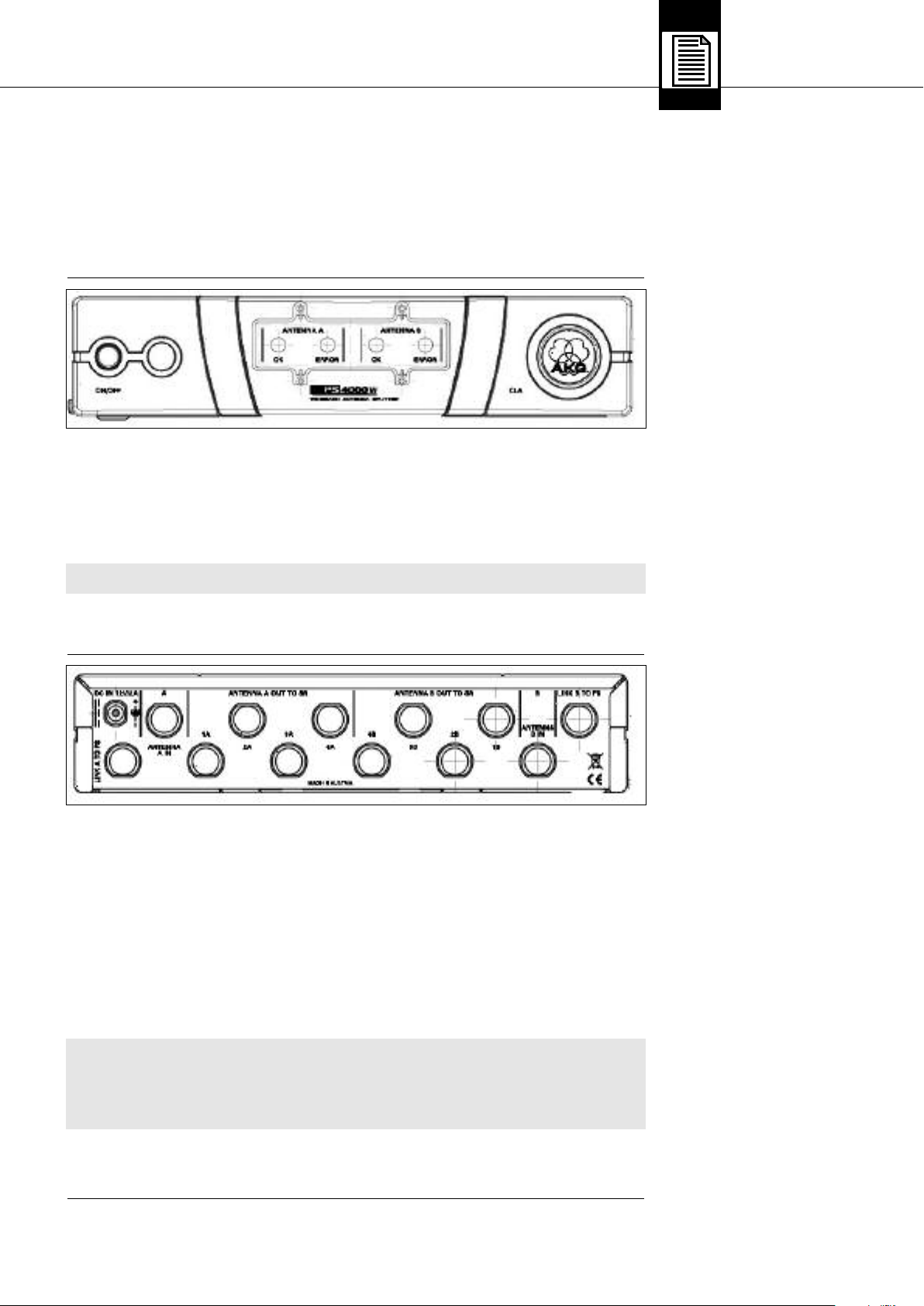
22..44..11 FFrroonnttppllaattttee
Fig. 1: Frontplatte des PS 4000 W
An der Frontplatte des Antennensplitters befinden sich folgende Bedienelemente und Anzeigen:
ON/OFF: Ein/Aus-Taste. Zum Einschalten des Geräts drücken Sie die Taste. Zum Ausschalten drücken Sie die Taste erneut.
AKG PS 4000 W 3
Page 4
2 Beschreibung
ANTENNA A, ANTENNA B: Die blaue OK-LED leuchtet, wenn an der Antennen-Eingangsbuchse ANTENNA A IN/ANTENNA B IN die kor-
rekte Vesorgungsspannung für aktive Komponenten bereitsteht.
Wenn die Versorgungsspannung an einem Antenneneingang kurzgeschlossen wird oder ausfällt (unter 2 V absinkt), erlischt die
jeweilige OK-LED und leuchtet die rote ERROR-LED auf.
AAnnmmeerrkkuunngg::
Siehe Tabelle 1 auf Seite 8.
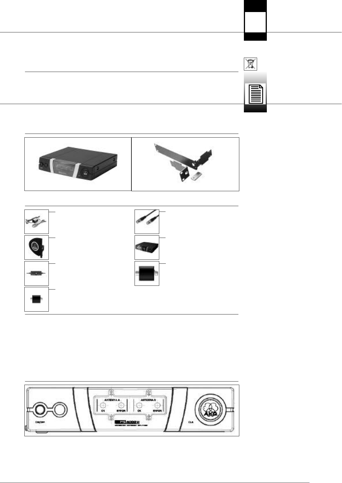
22..44..22 RRüücckksseeiittee
Fig. 2: Rückseite des PS 4000 W
• Die beiden OK-LEDs zeigen NICHT den Betriebszustand des jeweiligen Antennen verstärkers an und erlöschen daher nicht, wenn
Sie ein Antennenkabel abziehen.
CLA: Unter der Abdeckung mit dem AKG-Logo befindet sich ein dreistufiger DIP-Schalter zur Anpassung der Antenneneingänge
(ANTENNA A IN, ANTENNA B IN) an verschiedene Antennen-Kabellängen.
An der Rückseite des PS 4000 W stehen folgende Ein- und Ausgänge zur Verfügung:
DC IN 12 V/2 A: Eingangbuchse für ein 12 V DC-Netzgerät (optional) oder die optionale zentrale Strom versorgung PSU 4000.
ANTENNA A IN, ANTENNA B IN: BNC-Eingangsbuchsen für die abgesetzten Empfangsantennen SRA 2 B/W oder RA 4000 B/W. Für
Diversity-Empfänger benötigen Sie zwei Empfangsantennen (nicht mitgeliefert). Die Antennen-Eingangsbuchsen stellen eine
Versorgungs spannung von 12 V DC für aktive Antennen bereit.
ANTENNA A OUT TO SR: An den vier BNC-Ausgangsbuchsen 1A bis 4A steht das Antennensignal für den Empfangsteil A von bis
zu vier Diversity-Empfängern zur Verfügung. Alle unbenutzten Ausgänge werden automatisch elektrisch abgeschlossen.
ANTENNA B OUT TO SR: An den vier BNC-Ausgangsbuchsen 1B bis 4B steht das Antennensignal für den Empfangsteil B von bis
zu vier Diversity-Empfängern zur Verfügung. Alle unbenutzten Ausgänge werden automatisch elektrisch abgeschlossen.
Neben dem Antennensignal liefern die Ausgangsbuchsen 1A bis 4A sowie 1B bis 4B eine Versorgungsspannung von 12 V DC
für die angeschlossenen Empfänger.
Wichtig!
L
Siehe auch V
22..55 ZZeennttrraallee SSttrroommvveerrssoorrgguunngg
erkabelungsdiagramme
Fig. 10 bis 13.
PPSSUU 44000000 ((ooppttiioonnaall))
22..66 EEmmppffaannggssaanntteennnneenn
((ooppttiioonnaall))
22..66..11 SSRRAA 22 BB//WW
22..66..22 RRAA 44000000 BB//WW
• Der Strom an den Ausgangsbuchsen 1A bis 4B reicht nur dann zur Versorgung der angeschlossenen Empfänger aus,
!
wenn Sie den Antennensplitter an die optionale zentrale Stromversorgung PSU 4000 angeschlossen haben.
• Wenn Sie den Antennensplitter PS 4000 W mit einem eigenen (optionalen) Netzgerät betreiben, müssen Sie auch jeden
Empfänger mit einem separaten (optionalen) Netzgerät betreiben. Wenn Sie die Empfänger ohne Netzgerät an den
Antennensplitter anschließen, kann das Netzgerät des Antennensplitters durch Überlastung beschädigt werden.
LINK A TO PS, LINK B TO PS: An diesen BNC- Ausgangsbuchsen steht das HF-Signal der beiden Antennen A und B zur Verfügung.
Sie können die LINK-Buchsen mit den Antenneneingangsbuchsen eines weiteren Antennensplitters PS 4000 W verbinden und
auf diese Weise mehrere Antennensplitter kaskadieren.
Beachten Sie bitte, dass Sie für je drei Antennensplitter PS 4000 W eine optionale zentrale Stromversorgung PSU 4000 benötigen.
Die zentrale Stromversorgung PSU 4000 liefert eine Sekundärspannung von 12 V DC, 2 A für drei Antennensplitter PS 4000 W und
die daran angeschlossenen Empfänger (max. 12). Näheres entnehmen Sie bitte der Bedienungsanleitung der PSU 4000.
Für das Antennensystem PS 4000 W stehen passive und aktive Richtantennen sowie passive und aktive omnidirektionale Antennen
zur Verfügung. Alle Antennen sind Breitbandantennen für den gesamten UHF-Frequenzbereich.
Die aktiven Antennen werden vom Antennensplitter PS 4000 W über die Antennenkabel mit Strom versorgt. Bei komplexen Anlagen
mit langen Antennenkabeln empfehlen wir, die aktiven Antennen mit einer zentralen Stromversorgung PSU 4000 über je ein
Fernspeisegerät ASU 4000 zu betreiben.
Die SRA 2 B/W ist eine aktive Richtantenne mit robustem, wasserfestem Gehäuse für den Einsatz in Gebäuden oder im Freien und
eignet sich speziell zur Aufstellung in größerer Entfernung zum Aktions bereich. Ein integrierter Hochleistungs-Antennenverstärker
ermöglicht es, die Antenne bis zu 100 m vom Empfänger entfernt aufzustellen. Mit RG213-Antennenkabeln und 2 Antennen verstärkern AB 4000 in Serie können Sie die SRA 2 B/W sogar bis zu 200 m vom Empfänger entfernt positionieren.
Die Antenne ist mit einer BNC-Ausgangsbuchse, einer Funktionskontroll-LED und einem integrierten Stativanschluss ausgestattet.
Die RA 4000 B/W ist eine aktive omnidirektionale Antenne mit robustem, wasserfestem Gehäuse für den Einsatz in Gebäuden oder
im Freien und eignet sich speziell zur Aufstellung in der unmittelbaren Nähe des Aktionsbereichs. Ein integrierter HochleistungsAntennenverstärker ermöglicht es, die Antenne bis zu 100 m vom Empfänger entfernt aufzustellen. Mit RG213-Antennenkabeln und
2 Antennen verstärkern AB 4000 in Serie können Sie die RA 4000 B/W sogar bis zu 200 m vom Empfänger entfernt positionieren.
Die Antenne ist mit einer BNC-Ausgangsbuchse, einer Funktionskontroll-LED und einem integrierten Stativanschluss ausgestattet.
4
AKG PS 4000 W
Page 5
3 Inbetriebnahme
1. Schrauben Sie die vier Gummifüße (1) von der Unterseite des Antennensplitters ab.
2. Schrauben Sie die beiden Befestigungsschrauben (2) von jeder der beiden Seitenwände ab.
3. Befestigen Sie mit den Schrauben (2) den kurzen Montagewinkel (3) an der einen Seitenwand und den langen Montagewinkel (4)
aus dem mitgelieferten Montageset an der anderen Seitenwand.
4. Befestigen Sie den Antennensplitter im Rack.
1. Schrauben Sie die vier Gummifüße (1) von der Unterseite beider Antennensplitter ab und nehmen Sie die Schrauben (5) aus den
Gummifüßen (1) heraus.
2. Schrauben Sie die beiden Befestigungsschrauben (2) von der rechten Seitenwand des einen Antennensplitters und von der linken
Seitenwand des anderen Antennensplitters ab.
3. Ziehen Sie die Plastikabdeckungen (3) von jenen Seitenwänden ab, von denen Sie die Befestigungsschrauben (2) nicht abgeschraubt
haben.
4. Schieben Sie einen Verbindungsteil (4) durch je einen freien Schlitz in der Seitenwand des ersten Antennensplitters, so dass das
Befestigungsloch im Verbindungsteil mit dem Gewindeloch in der Unterseite des Antennensplitters fluchtet.
5. Fixieren Sie die beiden Verbindungsteile (4) mit zwei der Schrauben (5) (aus den Gummifüßen) am ersten Antennensplitter.
6. Verbinden Sie die beiden Antennensplitter, indem Sie die Verbindungsteile (4) am ersten Antennensplitter durch die freien Schlitze
in der Seitenwand des zweiten Antennensplitters schieben, bis das Befestigungsloch in beiden Verbindungsteilen (4) mit dem
entsprechenden Gewindeloch in der Unterseite des zweiten Antennensplitters fluchtet.
7. Fixieren Sie die Verbindungsteile (4) mit zwei der Schrauben (5) aus den Gummifüßen (1) am zweiten Antennensplitter.
8. Schrauben Sie mit je zwei der Schrauben (2) aus den Seitenwänden je einen kurzen Montagewinkel (6) an die äussere
Seitenwand jedes Antennensplitters.
9. Befestigen Sie die Antennensplitter im Rack.
• Bewahren Sie die restlichen Schrauben (5) für spätere Verwendung gut auf.
Die folgenden Hinweise zur Antennenaufstellung gelten für alle Einkanalanlagen sowie Mehrkanalanlagen unabhängig von der Anzahl
der Kanäle.
Reflexionen des Sendersignals an Metallteilen, Wänden, Decken, etc. oder Abschattungen durch menschliche Körper können das
direkte Sendersignal schwächen bzw. auslöschen. Positionieren Sie die Antennen daher wie folgt:
1. Positionieren Sie die Antennen immer in der Nähe des Aktionsbereichs (Bühne), achten Sie jedoch auf einen Mindestabstand
zwischen Sender und Antennen von 5 m und einen Mindestabstand zwischen den beiden Antennen von 20 cm.
2. Voraussetzung für optimalen Empfang ist Sichtverbindung zwischen Sender und Antenne.
3. Positionieren Sie die Antennen in einem Abstand von mehr als 1,5 m von großen metallenen Gegen-ständen, Draht (besonders
Maschendraht!) oder Metallblechen, Wänden, Bühnengerüsten, Decken, u.ä.
4. Stellen Sie die Antennen nicht in Wandnischen.
5. Positionieren Sie die Antennen mindestens 1,5 m von HF abstrahlenden Geräten wie Licht-Racks, Leuchtstoffröhren, digitalen
Effektgeräten und PCs entfernt.
6. Wenn Sie zwei Antennen nebeneinander aufstellen (z.B. für Diversity-Empfang), achten Sie darauf, dass diese mindestens 20 cm
voneinander entfernt sind.
3.1 Rackmontage eines
Antennensplitters
Siehe Fig. 8.
3.2 Rackmontage zweier
Antennensplitter neben einander
Siehe Fig. 9.
HHiinnwweeiiss::
33..33 AAnntteennnneenn aauuffsstteelllleenn
33..33..11 AA uuffsstteelllluunnggssoorrtt
≥ 70c m
˛
Wenn Sie die Antennen auf Bodenstativen montieren, beachten Sie bitte folgende
˛
Hinweise:
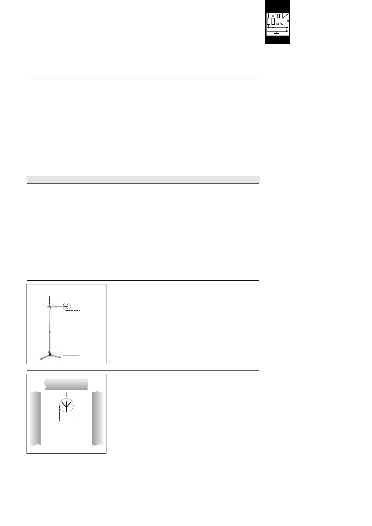
33..33..22 MMoonnttaaggee aauuff BBooddeennssttaattiivv
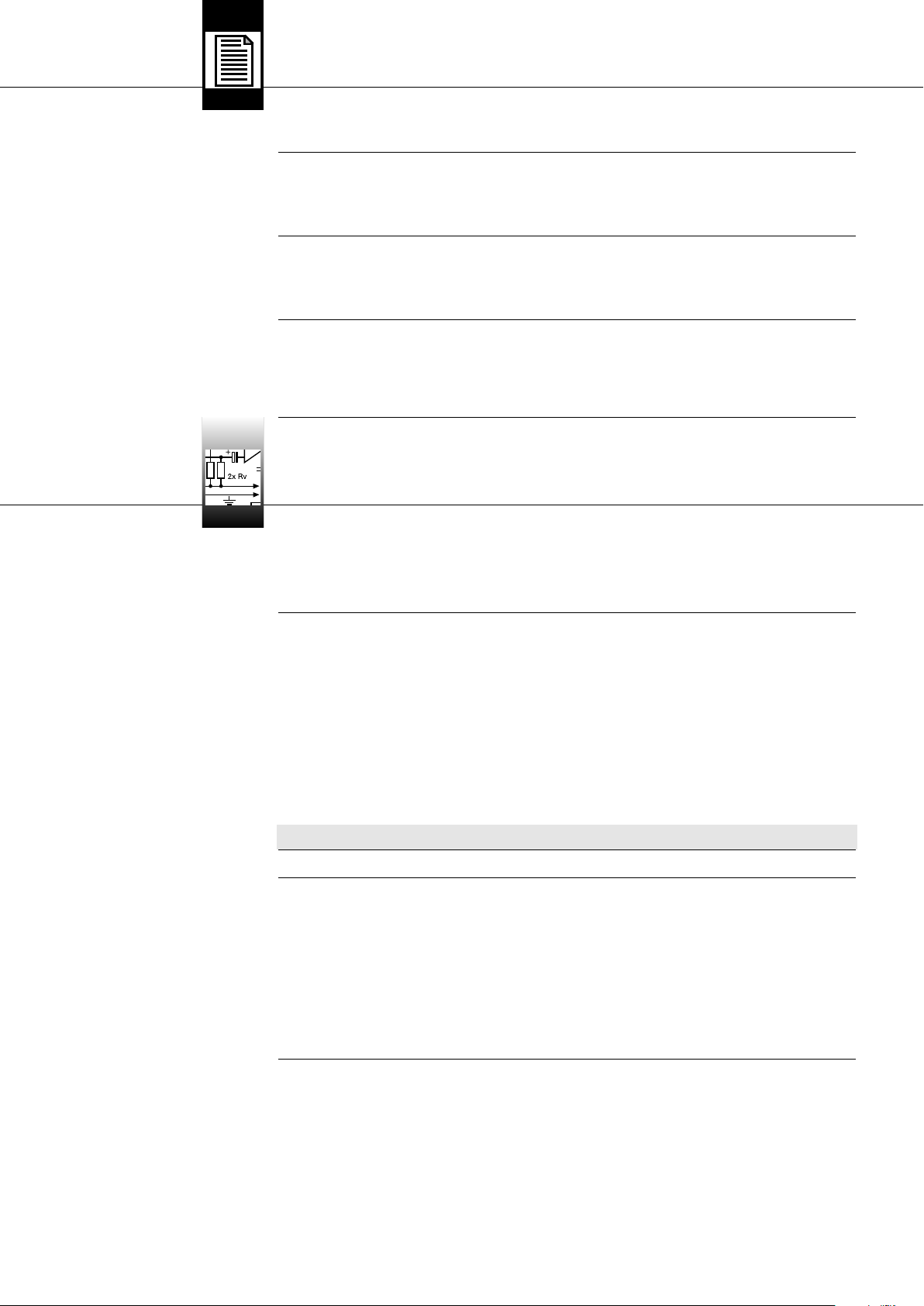
1. Befestigen Sie die Antenne mit dem mitgelieferten Stativ anschluss SA 63 bzw.
˛
mit dem integrierten Stativanschluss am Ausleger eines Galgenstativs.
2. Ziehen Sie den Ausleger ganz auf eine Seite, damit die Antenne mindestens 70
cm vom Stativ entfernt ist.
3. Ziehen sie das Stativ soweit aus, dass sich der Ausleger mindestens 1,8 m über
≥ 180cm
dem Boden befindet.
4. Wickeln Sie das Antennenkabel um den Ausleger. Das Kabel darf nicht herunterhängen, da es sonst die Empfangsqualität beeinträchtigen kann.
˛
Fig. 3: Antenne auf Bodenstativ montiert
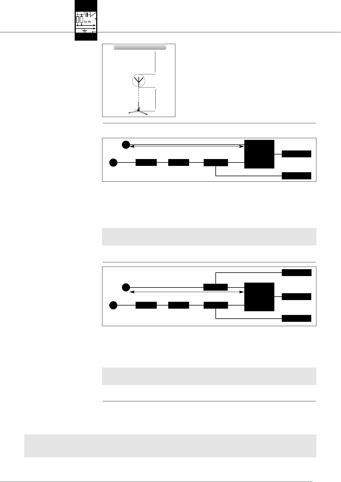
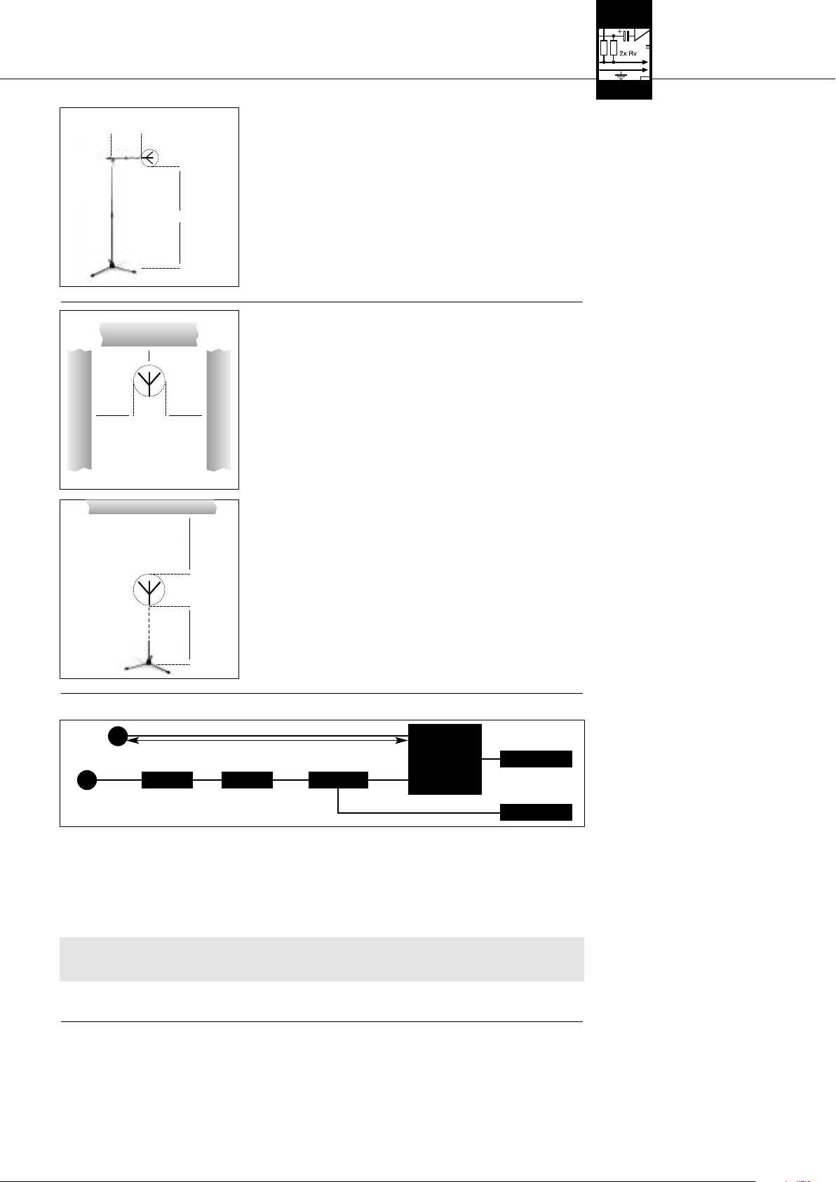
Wenn Sie Ihre Antennen an der Wand oder Decke montieren, achten Sie auf folgen-
33..33..33 WWaanndd--//DDeecckkeennmmoonnttaaggee
de Mindestabstände:
˛
˛
≥ 10cm
1. Montieren Sie die Antenne mindestens 10 cm vor bzw. in einem seitlichen
Abstand von mindestens 50 cm von Wänden oder anderen ebenen Flächen bzw.
Metallgittern oder Metallgerüsten.
˛
˛
˛
˛
≥ 50c m≥ 50c m
Fig. 4: Mindestabstand von ebenen Flächen
AKG PS 4000 W 5
Page 6
3 Inbetriebnahme
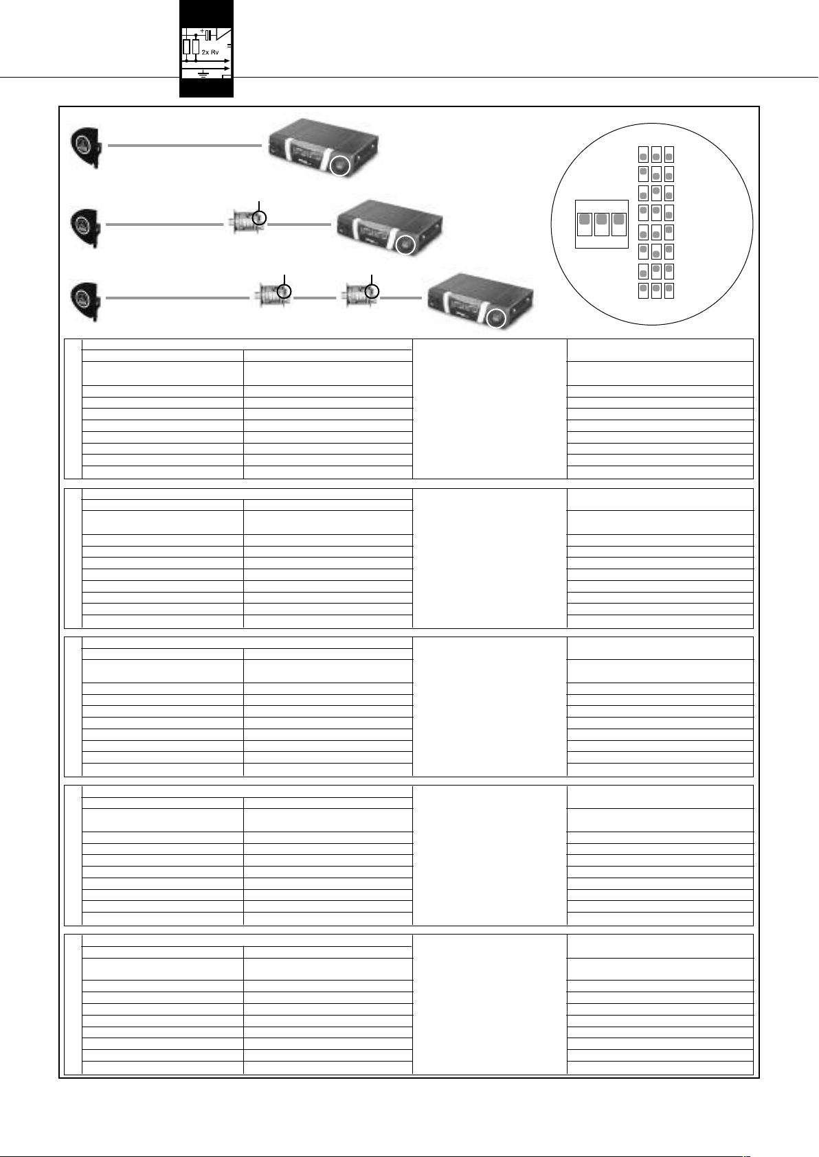
Fig. 5: Mindestabstand
von Boden und Decke
33..44 AAnntteennnneenn aannsscchhlliieeßßeenn
33..44..11 EEiinnkkaannaallaannllaaggee
mmiitt ppaassssiivveenn AAnntteennnneenn
Siehe Tabelle 1 auf Seite 8
und Fig. 6.
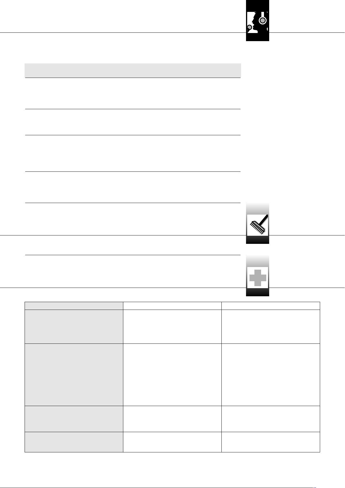
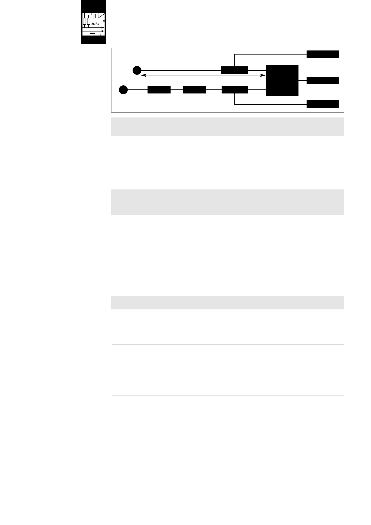
Fig. 6: Verkabelung einer Einkanalanlage
mit passiven Antennen und unterschiedlich
langen Antennenleitungen.
Siehe Fig. 6.
˛
≥ 50 (15) cm
˛
˛
≥ 15cm
˛
Für eine Einkanalanlage benötigen Sie keinen Antennensplitter. Sie können die Antennen mit dem Empfänger verbinden.
Antenne
AA BB BB
Antenne
AA::
RG58: 0 - 13 m / RG213: 5 - 26 m
BB::
RG58: 6 - 46 m / RG213: 12 - 97 m
1. Stellen Sie die Länge der Kabelstrecken zwischen dem Empfänger und den beiden Antennen fest.
2. Entnehmen Sie der Tabelle 1 auf Seite 8, ob Sie die gesamte Kabelstrecke in mehrere Kabel unterteilen müssen und einen oder
zwei Antennenverstärker AB 4000 benötigen. Tabelle 1 gibt die maximale zulässige Kabellänge je nach Kabeltyp an.
3. Stecken Sie an jede Antenne ein Antennenkabel an.
4. Verbinden Sie die beiden Antennen gemäß Tabelle 1 mit den Antennen-Eingangsbuchsen des Empfängers.
Wenn Sie einen oder zwei Antennenverstärker AB 4000 benötigen, müssen Sie zwischen dem Empfänger und dem ersten
Antennenverstärker ein Fernspeisegerät ASU 4000 in die Leitung einfügen.
RG58: 0 - 13 m / RG213: 5 - 26 m
AABB 44000000
2. Achten Sie darauf, dass die Antenne mindestens 15 cm vom Boden bzw. 50 cm
(bei Kabelzuführung von oben: 15 cm) von der Decke entfernt ist.
<<-- DDCC//AACC -->>
<<-- DDCC//AACC -->>
AABB 44000000
EEmmppffäännggeerr
AASSUU 44000000
Wichtig!
!
L
33..44..22 EEiinnkkaannaallaannllaaggee
mm iitt aakkttiivveenn AAnntteennnneenn
Siehe Tabelle 1 auf Seite 8
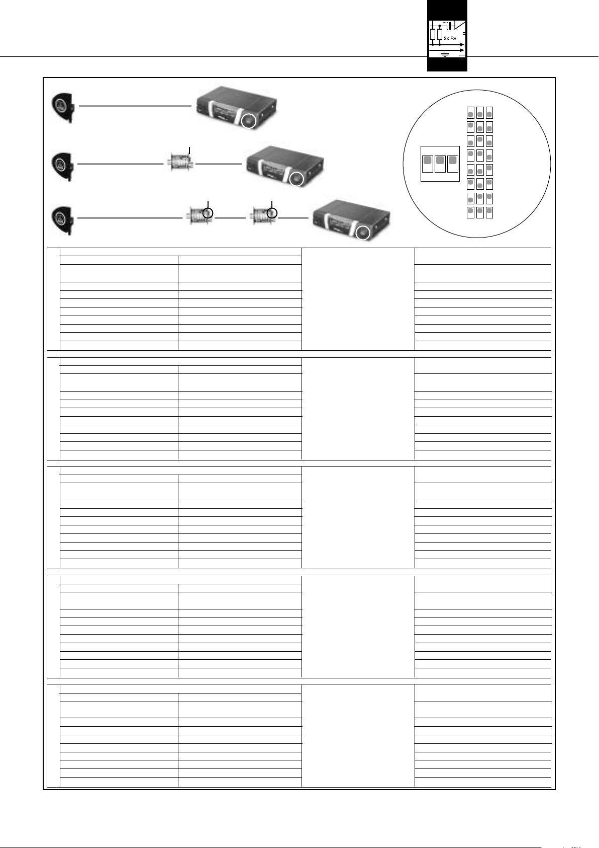
Fig. 7: Verkabelung einer Einkanalanlage
mit aktiven Antennen und unterschiedlich
langen Antennenleitungen.
und Fig. 7.
Siehe Fig. 7.
Wichtig!
L
!
5. Kontrollieren Sie, ob die an den Netzgeräten des ASU 4000 und des Empfängers angegebene Netzspannung mit der
Netzspannung am Einsatzort übereinstimmt. Der Betrieb der Netzgeräte an einer anderen Netzspannung kann zu
Schäden am Gerät führen.
6. Verbinden Sie das Fernspeisegerät sowie den Empfänger mit den zugehörigen Netzgeräten und jedes Netzgerät mit einer geeigneten Netzsteckdose.
<<-- DDCC//AACC -->>
SRA 2 B/W
RG58: 0 - 13 m / RG213: 5 - 26 m
AABB 44000000
AA BB BB
SRA 2 B/W
1. Stellen Sie die Länge der Kabelstrecken zwischen dem Empfänger und den beiden aktiven Antennen fest.
2. Entnehmen Sie der Tabelle 1 auf Seite 8, ob Sie die gesamte Kabelstrecke in mehrere Kabel unterteilen müssen und einen oder
3. Stecken Sie an jede Antenne ein Antennenkabel an.
4. Verbinden Sie beide Antennen gemäß Tabelle 1 mit einem oder zwei Antennenverstärkern AB 4000, je einem Fernspeisegerät
5. Kontrollieren Sie, ob die an den Netzgeräten der beiden ASU 4000 und des Empfängers angegebene Netzspannung mit
6. Verbinden Sie die beiden Fernspeisegeräte sowie den Empfänger mit den zugehörigen Netzgeräten und jedes Netzgerät mit einer
AA::
RG58: 0 - 13 m / RG213: 5 - 26 m
BB::
RG58: 6 - 46 m / RG213: 12 - 97 m
zwei Antennenverstärker AB 4000 benötigen. Tabelle 1 gibt die maximale zulässige Kabellänge je nach Kabeltyp an.
ASU 4000 und mit den Antennen-Eingangsbuchsen des Empfängers.
der Netzspannung am Einsatzort übereinstimmt. Der Betrieb der Netzgeräte an einer anderen Netzspannung kann zu
Schäden am Gerät führen.
geeigneten Netzsteckdose.
AABB 44000000 AASSUU 44000000
AASSUU 44000000
EEmmppffäännggeerr
<<-- DDCC//AACC -->>
<<-- DDCC//AACC -->>
mm iitt AAnntteennnneennsspplliitttteerr PPSS 44000000 WW
33..55 MMeehhrrkkaannaallaannllaaggeenn
Warnung!
6
Verkabelungsbeispiele für Mehrkanalanlagen finden Sie in Fig. 10 bis 13 auf Seite 56.
Beachten Sie beim Aufbau einer Mehrkanalananlage folgende Punkte:
1. An den Antennensplitter PS 4000 W können Sie bis zu vier Empfänger anschließen.
• Wenn Sie sowohl den Antennensplitter als auch die Empfänger mit jeweils einem eigenen (optionalen) Netzgerät
!
L
betreiben, verbinden Sie unbedingt zuerst die Netzgeräte der Empfänger mit dem Netz, bevor Sie das Netzgerät des
Antennensplitters mit dem Netz verbinden. Wenn Sie zuerst den Antennensplitter an das Netz anschließen, kann das
Netzgerät des Antennen splitters infolge der Belastung durch die Empfänger beschädigt werden.
AKG PS 4000 W
Page 7

3 Inbetriebnahme
2. Für größere
• Verbinden Sie die LINK-Buchsen des ersten Antennensplitters jeweils mit den ANTENNA IN-Buchsen des nächsten
• Zur Stromversorgung derarttiger Anlagen empfehlen wir die optionale zentrale Stromversorgung PSU 4000 für je drei
3. Jeder Antenneneingang des Antennensplitters ist in der Lage, maximal drei aktive Komponenten (z.B. RA 4000 B/W + 2 x
AB 4000) über die Antennenkabel mit Strom zu versorgen.
In folgenden Fällen benötigen Sie ein Fernspeisegerät ASU 4000 zur Speisung aktiver Komponenten (das ASU 4000 kann ebenfalls drei aktive Komponenten speisen):
• Die Kabelstrecke zwischen Antennensplitter und aktiver Komponente ist so lang, dass die Versorgungsspannung unter den
• Zwischen PS 4000 W und aktiver Komponente befindet sich ein Gerät (z.B. ein Antennen-Combiner*), das die DC-
* Der Antennen-Combiner ZAPD 21 der Firma Mini Circuit lässt die Versorgungsspannung durch, bei anderen Fabrikaten ist
• Sie haben mittels eines Antennen-Combiners zwei Antennenleitungen an einen Antenneneingang angeschlossen. Wenn Sie
Der HF-Signalpegel an jedem Antenneneingang des (der) Antennensplitter hängt vom Frequenzband, Antennentyp, Kabeltyp und von
der Kabellänge ab.
Um den optimalen HF-Signalpegel am Antenneneingang sicherzustellen, müssen Sie den CLA-Schalter an jedem Antennenverstärker
sowie am (an den) Antennensplitter(n) gemäß Tabelle 1 einstellen.
1. Entfernen Sie die Abdeckung des CLA-Schalters.
2. Stellen Sie die drei DIP-Schalter je nach Frequenzband, Antennentyp, Kabeltyp und Kabellänge ein.
3. Bringen Sie die Abdeckung wieder an.
Anlagen mit bis zu 50 Kanälen können Sie eine entsprechende Anzahl von Antennen splittern zusammenschalten:
Antennensplitters und so weiter.
Antennensplitter und vier Empfänger.
zulässigen Mindestwert absinkt.
Versorgungsspannung im Antennenkabel unterbricht.
dies nicht gewährleistet.
in einer Antennenleitung drei oder mehr aktive Komponenten betreiben, schalten Sie zwischen den Antennen-Combiner und
die erste dieser aktiven Komponenten ein Fernspeisegerät ASU 4000. Wenn Sie in beiden Antennenleitungen zusammen
mehr als drei aktive Komponenten betreiben, benötigen Sie für jede Antennenleitung ein Fernspeisegerät ASU 4000. Das
Fernspeisegerät ist erforderlich, um eine Überlastung der Stromversorgung des Antennen splitters zu verhindern.
HHiinnwweeiiss::
33..66 CCLLAA--SScchhaalltteerr
Siehe Tabelle 1 auf Seite 8.
AKG PS 4000 W 7
Page 8
3 Inbetriebnahme
A
CLA
A B
CLA
A
CLA
CLA
B B
CLA
CLA
CLA
ON
1 2 3
14 dB
12 dB
10 dB
8 dB
6 dB
4 dB
2 dB
0 dB
RG58 RG213 CLA RG58 RG213 CLA RG58 RG213 CLA
53 - 57 111 - 121 0 38 - 43 79 - 89 0 41 - 46 87 - 97 0
48 - 53 100 - 111 2 33 - 38 68 - 79 2 36 - 41 76 - 87 2
43 - 48 89 - 100 4 28 - 33 58 - 68 4 31 - 36 66 - 76 4
38 - 43 79 - 89 6 23 - 28 47 - 58 6 26 - 31 55 - 66 6
BAND I + IIBAND III + IVBAND V + VI
33 - 38 68 - 79 8 18 - 23 37 - 47 8 21 - 26 45 - 55 8
28 - 33 58 - 68 10 13 - 18 26 - 37 10 16 - 21 34 - 45 10
23 - 28 47 - 58 12 8 - 13 16 - 26 12 11 - 16 24 - 34 12
18 - 23 37 - 47 14 3 - 8 5 - 16 14 6 - 11 13 - 24 14
RG58 RG213 CLA RG58 RG213 CLA RG58 RG213 CLA RG58 RG213 CLA
50 - 55 105 - 115 0 36 - 40 75 - 85 0 7 - 12 15 - 25 0 39 - 44 83 - 93 0
45 - 50 95 - 105 2 31 - 36 65 - 75 2 2 - 7 5 - 15 2 35 - 39 73 - 83 2
40 - 45 85 - 95 4 26 - 31 55 - 65 4 0 - 2 4 30 - 35 63 - 73 4
36 - 40 75 - 85 6 21 - 26 45 - 55 6625 - 30 53 - 63 6
31 - 36 65 - 75 8 17 - 21 35 - 45 8820 - 25 43 - 53 8
26 - 31 55 - 65 10 12 - 17 25 - 35 10 10 15 - 20 33 - 43 10
21 - 26 45 - 55 12 7 - 12 15 - 25 12 12 11 - 15 23 - 33 12
17 - 21 35 - 45 14 2 - 7 5 - 15 14 14 6 - 11 13 - 23 14
RG58 RG213 CLA RG58 RG213 CLA RG58 RG213 CLA RG58 RG213 CLA
47 - 51 100 - 110 0 33 - 38 71 - 81 0 7 - 11 14 - 24 0 37 - 41 79 - 88 0
42 - 47 90 - 100 2 29 - 33 62 - 71 2 2 - 7 5 - 14 2 32 - 37 69 - 79 2
38 - 42 81 - 90 4 24 - 29 52 - 62 4 0 - 2 4 28 - 32 60 - 69 4
34 - 38 71 - 81 6 20 - 24 43 - 52 6623 - 28 50 - 60 6
29 - 34 62 - 71 8 16 - 20 33 - 43 8819 - 23 40 - 50 8
24 - 29 52 - 62 10 11 - 16 24 - 33 10 10 14 - 19 31 - 40 10
20 - 24 43 - 52 12 7 - 11 14 - 24 12 12 10 - 14 21 - 31 12
16 - 20 33 - 43 14 2 - 7 5 - 14 14 14 6 - 10 12 - 21 14
RG58 RG213 CLA RG58 RG213 CLA RG58 RG213 CLA
56 - 60 132 - 140 0 44 - 46 102 - 108 0 49 - 50 110 - 118 0
51 - 56 120 - 132 2 40 - 44 93 - 102 2 47 - 49 100 - 110 2
46 - 51 108 - 120 4 36 - 40 84 - 93 4 42 - 47 90 - 100 4
BAND VII
41 - 46 97 - 108 6 32 - 36 75 - 84 6 36 - 42 81 - 90 6
36 - 41 83 - 97 8 28 - 32 66 - 75 8 31 - 36 70 - 81 8
31 - 36 71 - 83 10 25 - 28 57 - 66 10 27 - 31 60 - 70 10
26 - 31 60 - 71 12 21 - 25 48 - 57 12 23 - 27 50 - 60 12
23 - 26 52 - 60 14 18 - 21 42 - 48 14 19 - 23 44 - 50 14
RG58 RG213 CLA RG58 RG213 CLA RG58 RG213 CLA
53 - 56 122 - 131 0 40 - 44 94 - 101 0 43 - 46 102 - 107 0
48 - 53 110 - 122 2 35 - 40 82 - 94 2 38 - 43 88 - 102 2
43 - 48 99 - 110 4 30 - 35 70 - 82 4 33 - 38 76 - 88 4
BAND VIII
38 - 43 88 - 99 6 25 - 30 58 - 70 6 28 - 33 64 - 76 6
33 - 38 79 - 88 8 22 - 25 46 - 58 8 23 - 28 52 - 64 8
28 - 33 63 - 74 10 16 - 22 34 - 46 10 18 - 23 40 - 52 10
23 - 28 50 - 63 12 11 - 16 22 - 34 12 13 - 18 28 - 40 12
20 - 23 43 - 50 14 7 - 11 15 - 22 14 10 - 13 20 - 28 14
SRA 2 B/W RA 4000 B/W
(m) (m) (dB) (m) (m) (dB) (m) (m) (dB)
SRA 2 B/W RA 4000 B/W
(m) (m) (dB) (m) (m) (dB) (m) (m) (dB) (m) (m) (dB)
SRA 2 B/W RA 4000 B/W
(m) (m) (dB) (m) (m) (dB) (m) (m) (dB) (m) (m) (dB)
SRA 2 B/W RA 4000 B/W
(m) (m) (dB) (m) (m) (dB) (m) (m) (dB)
SRA 2 B/W RA 4000 B/W
(m) (m) (dB) (m) (m) (dB) (m) (m) (dB)
A
A
A
A
A
Tabelle 1: Stellung der CLA-Schalter je nach Frequenzband, Antenne, Kabeltyp und Kabellänge
B
B
B
B
B
8
AKG PS 4000 W
Page 9
4 Betriebshinweise
1. Achten Sie darauf, jeden Sendekanal (Sender + Empfänger) auf eine eigene Frequenz einzustellen.
2. Betreiben Sie nie
Gründen zu starken Störgeräuschen führen.
• Halten Sie beim Ein- und Ausschalten der Anlage die in Kapitel 4.2 und 4.3 angegebene Reihen folge unbedingt ein, um
Schäden durch Überlastung der Stromversorgung des Antennen splitters zu vermeiden.
1. Schalten Sie die Sender ein.
2. Schalten Sie alle mit dem Antennensplitter verbundenen Empfänger ein.
3. Schalten Sie den Antennensplitter ein, indem Sie die ON/OFF-Taste drücken.
Die blauen OK-LEDs am Antennensplitter sowie die grünen Kontroll-LEDs der angeschlossenen aktiven Komponenten leuchten
auf.
1. Schalten Sie alle mit dem Antennensplitter verbundenen Empfänger aus.
2. Schalten Sie die Sender aus.
3. Schalten Sie den Antennensplitter aus, indem Sie die ON/OFF-Taste drücken.
Die blauen OK-LEDs am Antennensplitter sowie die grünen Kontroll-LEDs der angeschlossenen aktiven Komponenten erlöschen.
1. Schalten Sie die zentrale Stromversorgung PSU 4000 ein.
2. Schalten Sie die Sender ein.
3. Schalten Sie den Antennensplitter ein, indem Sie die ON/OFF-Taste drücken.
Die blauen OK-LEDs am Antennensplitter sowie die grünen Kontroll-LEDs der angeschlossenen aktiven Komponenten leuchten
auf.
4. Schalten Sie alle mit dem Antennensplitter verbundenen Empfänger ein.
1. Schalten Sie alle mit dem Antennensplitter verbundenen Empfänger aus.
2. Schalten Sie die Sender aus.
3. Schalten Sie den Antennensplitter aus, indem Sie die ON/OFF-Taste drücken.
Die blauen OK-LEDs am Antennensplitter sowie die grünen Kontroll-LEDs der angeschlossenen aktiven Komponenten erlöschen.
4. Schalten Sie die zentrale Stromversorgung PSU 4000 aus.
mehr als einen Sendekanal gleichzeitig am selben Ort auf derselben Frequenz. Dies würde aus physikalischen
44..11 AAllllggeemm eeiinnee HHiinnww eeiissee
WWiicchhttiigg!!
!
L
44..22 AAnnllaaggeenn mmiitt ddeezzeennttrraalleerr
SSttrroommvveerrssoorrgguunngg
44..22..11 EEiinnsscchhaalltteenn
44..22..22 AA uusssscchhaalltteenn
44..33 AAnnllaaggeenn mmiitt ooppttiioonnaalleerr zzeennttrraalleerr
SSttrroommvveerrssoorrgguunngg PPSSUU 44000000
44..33..11 EEiinnsscchhaalltteenn
44..33..22 AA uusssscchhaalltteenn
5 Reinigung
• Zum Reinigen der Oberflächen des Antennensplitters verwenden Sie am besten ein mit Wasser befeuchtetes weiches Tuch.
6 Fehlerbehebung
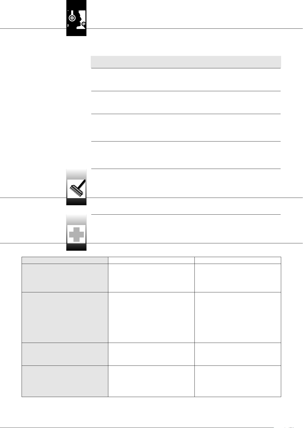
Fehler Mögliche Ursache Behebung
Kein Ton.
Kein oder gestörter Empfang auf
einzelnen Kanälen.
1. Netzgeräte/PSU 4000 nicht an Netz steckdose angeschlossen.
2. DC-Kabel nicht angeschlossen oder defekt.
3. Antennen nicht angeschlossen.
4. Netzgerät(e)/PSU 4000 defekt.
1. Sender und/oder Empfänger ist (sind) nicht eingeschaltet.
2. Senderbatterie(n) leer.
3. Netzgerät des Empfängers bzw. Verbindungskabel vom
PSU 4000 zum Empfänger
a) hat schlechten Kontakt oder
b) ist defekt.
4. Sender und Empfänger des betreffenden Kanals sind
nicht auf dieselbe Frequenz eingestellt.
5. Sender oder Empfänger defekt.
1. Netzgeräte/PSU 4000 an Netz steckdose anschließen.
2. DC-Kabel anschließen oder austauschen.
3. Antennen anschließen.
4. Wenden Sie sich an Ihre AKG-Servicestelle.
1. Sender und/oder Empfänger einschalten.
2. Senderbatterie(n) austauschen.
3. a) Stecker des Netzgeräts bzw. Verbindungskabels auf
b) Netzgerät bzw. Verbindungskabel austauschen.
4. Sender und Empfänger auf dieselbe Frequenz einstellen. Lesen Sie dazu die Bedienungsanleitung des
Senders und Empfängers nach.
5. Wenden Sie sich an Ihre AKG-Servicestelle.
sicheren Sitz überprüfen oder
Grüne LED an einer aktiven Antennenkomponente
leuchtet nicht.
Eine der ERROR-LEDs am Antennen -
splitter leuchtet auf.
AKG PS 4000 W
1. Antennenkabel nicht angeschlossen bzw. hat schlechten Kontakt.
2. Antennenkabel defekt.
3. Aktive Antennenkomponente defekt.
1. Versorgungsspannung für aktive
Antennenkomponenten kurzgeschlossen.
1. Antennenkabel anschließen bzw. Stecker auf sicheren
Sitz überprüfen.
2. Antennenkabel austauschen.
3. Wenden Sie sich an Ihre AKG-Servicestelle.
1. Alle angeschlossenen Kabel und aktiven
Antennenkomponenten überprüfen. Defekte Kabel
und/oder Komponenten austauschen.
9
Page 10
6 Fehlerbehebung
Fehler Mögliche Ursache Behebung
(Eine der ERROR-LEDs am Antennen -
splitter leuchtet auf.)
2. Versorgungsspannung für aktive
Antennenkomponenten auf Grund zu großer
Kabellängen zu niedrig.
2. Längen der angeschlossenen Kabel anhand Tabelle 1
überprüfen und kürzere Kabel verwenden oder Kabel
unterteilen und ASU 4000 einfügen (s.a. Verkabelungs diagramme).
7 Technische Daten
Antennensplitter PS 4000 W
Typ: 2 x 1 auf 4 Empfänger + 2 x 1 PS (kaskadierbar)
Trägerfrequenzbereich: 500 - 865 MHz
Dämpfung: 0, 2, 4, 6, 8, 10, 12, 14 dB, schaltbar
HF-Eingänge: 2 BNC-Buchsen, 50 Ohm
HF-Ausgänge: 10 BNC Buchsen, 50 Ohm
Versorgungsspannung: 12 V DC
Abmessungen: 200 x 190 x 44 mm
Gewicht: ca. 970 g
Antennenverstärker AB 4000
Trägerfrequenzbereich: 500 - 865 MHz
Verstärkung: ca. 17 - 3,5 dB, schaltbar
HF-Eingang: 1 BNC-Buchse, 50 Ohm
HF-Ausgang: 1 BNC-Buchse, 50 Ohm
Versorgungsspannung: 8 V DC zugeführt über Antennenkabel von PS 4000 W oder ASU 4000
Abmessungen: 110 x 35 mm
Gewicht: ca. 150 g
Omnidirektionale Booster-Antenne RA 4000 B/W
Trägerfrequenzbereich: 500 - 865 MHz
Gewinn + Verstärkung: 17dB
HF-Eingang: 1 BNC-Buchse, 50 Ohm
HF-Ausgang: 1 BNC-Buchse, 50 Ohm
Versorgungsspannung: 8 V DC zugeführt über Antennenkabel von PS 4000 W oder ASU 4000
Abmessungen: 235 x 38,5 mm
Gewicht: 65 g
Aktive Richtantenne SRA 2 B/W
Trägerfrequenzbereich: 500 - 865 MHz
Gewinn + Verstärkung: 21,5 dB
Öffnungswinkel: 70°
Abmessungen: 230 x 240 x 26 mm
Gewicht: ca. 250 g
Fernspeisegerät ASU 4000
Trägerfrequenzbereich: 500 - 865 MHz
HF-Eingang: 1 BNC-Buchse, 50 Ohm
HF-Ausgang: 1 BNC-Buchse, 50 Ohm
Versorgungsspannung: 12 V DC
Abmessungen: 78 x 50 x50 mm
Gewicht: ca. 150 g
Dieses Produkt entspricht den in der Konformitätserklärung angegebenen Normen. Sie können die Konformitätserklärung auf http://www.akg.com oder per E-Mail an
sales@akg.com anfordern.
10 AKG PS 4000 W
Page 11
Table of Contents
FCC Statement . . . . . . . . . . . . . . . . . . . . . . . . . . . . . . . . . . . . . . . . . . . . . . . . . . . . . . . . . . . . . . . . . . . . . . . . . . 11
1 Safety and Environment . . . . . . . . . . . . . . . . . . . . . . . . . . . . . . . . . . . . . . . . . . . . . . . . . . . . . . . . . . . . . . . . 12
1.1 Safety . . . . . . . . . . . . . . . . . . . . . . . . . . . . . . . . . . . . . . . . . . . . . . . . . . . . . . . . . . . . . . . . . . . . . . . . . . 12
1.2 Environment. . . . . . . . . . . . . . . . . . . . . . . . . . . . . . . . . . . . . . . . . . . . . . . . . . . . . . . . . . . . . . . . . . . . . . 12
2 Description . . . . . . . . . . . . . . . . . . . . . . . . . . . . . . . . . . . . . . . . . . . . . . . . . . . . . . . . . . . . . . . . . . . . . . . . . . 12
2.1 Introduction . . . . . . . . . . . . . . . . . . . . . . . . . . . . . . . . . . . . . . . . . . . . . . . . . . . . . . . . . . . . . . . . . . . . . . 12
2.2 Packing List. . . . . . . . . . . . . . . . . . . . . . . . . . . . . . . . . . . . . . . . . . . . . . . . . . . . . . . . . . . . . . . . . . . . . . 12
2.3 Optional Accessories . . . . . . . . . . . . . . . . . . . . . . . . . . . . . . . . . . . . . . . . . . . . . . . . . . . . . . . . . . . . . . . 12
2.4 Description . . . . . . . . . . . . . . . . . . . . . . . . . . . . . . . . . . . . . . . . . . . . . . . . . . . . . . . . . . . . . . . . . . . . . . 13
2.4.1 Front Panel . . . . . . . . . . . . . . . . . . . . . . . . . . . . . . . . . . . . . . . . . . . . . . . . . . . . . . . . . . . . . . . . . . 13
2.4.2 Rear Panel . . . . . . . . . . . . . . . . . . . . . . . . . . . . . . . . . . . . . . . . . . . . . . . . . . . . . . . . . . . . . . . . . . 13
2.5 PSU 4000 Central Power Supply (optional) . . . . . . . . . . . . . . . . . . . . . . . . . . . . . . . . . . . . . . . . . . . . . . . 14
2.6 Receiving Antennas (optional) . . . . . . . . . . . . . . . . . . . . . . . . . . . . . . . . . . . . . . . . . . . . . . . . . . . . . . . . . 14
2.6.1 SRA 2 B/W . . . . . . . . . . . . . . . . . . . . . . . . . . . . . . . . . . . . . . . . . . . . . . . . . . . . . . . . . . . . . . . . . . 14
2.6.2 RA 4000 B/W . . . . . . . . . . . . . . . . . . . . . . . . . . . . . . . . . . . . . . . . . . . . . . . . . . . . . . . . . . . . . . . . 14
3 Getting Started . . . . . . . . . . . . . . . . . . . . . . . . . . . . . . . . . . . . . . . . . . . . . . . . . . . . . . . . . . . . . . . . . . . . . . . 14
3.1 Rack Mounting a Single Antenna Splitter . . . . . . . . . . . . . . . . . . . . . . . . . . . . . . . . . . . . . . . . . . . . . . . . . 14
3.2 Rack Mounting Two Antenna Splitter s Side by Side . . . . . . . . . . . . . . . . . . . . . . . . . . . . . . . . . . . . . . . . . 14
3.3 Setting Up Antennas. . . . . . . . . . . . . . . . . . . . . . . . . . . . . . . . . . . . . . . . . . . . . . . . . . . . . . . . . . . . . . . . 14
3.3.1 Placement . . . . . . . . . . . . . . . . . . . . . . . . . . . . . . . . . . . . . . . . . . . . . . . . . . . . . . . . . . . . . . . . . . 14
3.3.2 Mounting Antennas on Floor Stands . . . . . . . . . . . . . . . . . . . . . . . . . . . . . . . . . . . . . . . . . . . . . . . . 15
3.3.3 Wall/Ceiling Mounting . . . . . . . . . . . . . . . . . . . . . . . . . . . . . . . . . . . . . . . . . . . . . . . . . . . . . . . . . . 15
3.4 Connecting Antennas . . . . . . . . . . . . . . . . . . . . . . . . . . . . . . . . . . . . . . . . . . . . . . . . . . . . . . . . . . . . . . . 15
3.4.1 Single-channel System with Passive Antennas . . . . . . . . . . . . . . . . . . . . . . . . . . . . . . . . . . . . . . . . 15
3.4.2 Single-channel System with Active Antennas . . . . . . . . . . . . . . . . . . . . . . . . . . . . . . . . . . . . . . . . . 15
3.5 Multichannel Systems with PS 4000 W Antenna Splitters. . . . . . . . . . . . . . . . . . . . . . . . . . . . . . . . . . . . . 16
3.6 The CLA Switch Bank . . . . . . . . . . . . . . . . . . . . . . . . . . . . . . . . . . . . . . . . . . . . . . . . . . . . . . . . . . . . . . . 16
4 Operating Notes . . . . . . . . . . . . . . . . . . . . . . . . . . . . . . . . . . . . . . . . . . . . . . . . . . . . . . . . . . . . . . . . . . . . . . 18
4.1 General Hints . . . . . . . . . . . . . . . . . . . . . . . . . . . . . . . . . . . . . . . . . . . . . . . . . . . . . . . . . . . . . . . . . . . . . 18
4.2 Systems with Distributed Power Supplies . . . . . . . . . . . . . . . . . . . . . . . . . . . . . . . . . . . . . . . . . . . . . . . . 18
4.2.1 Powering Up . . . . . . . . . . . . . . . . . . . . . . . . . . . . . . . . . . . . . . . . . . . . . . . . . . . . . . . . . . . . . . . . . 18
4.2.2 Powering Down. . . . . . . . . . . . . . . . . . . . . . . . . . . . . . . . . . . . . . . . . . . . . . . . . . . . . . . . . . . . . . . 18
4.3 Systems with PS 4000 W Optional Central Power Supplies. . . . . . . . . . . . . . . . . . . . . . . . . . . . . . . . . . . . 18
4.3.1 Powering Up . . . . . . . . . . . . . . . . . . . . . . . . . . . . . . . . . . . . . . . . . . . . . . . . . . . . . . . . . . . . . . . . . 18
4.3.2 Powering Down. . . . . . . . . . . . . . . . . . . . . . . . . . . . . . . . . . . . . . . . . . . . . . . . . . . . . . . . . . . . . . . 18
5 Cleaning . . . . . . . . . . . . . . . . . . . . . . . . . . . . . . . . . . . . . . . . . . . . . . . . . . . . . . . . . . . . . . . . . . . . . . . . . . . . 18
6 Troubleshooting . . . . . . . . . . . . . . . . . . . . . . . . . . . . . . . . . . . . . . . . . . . . . . . . . . . . . . . . . . . . . . . . . . . . . . 18
7 Specifications . . . . . . . . . . . . . . . . . . . . . . . . . . . . . . . . . . . . . . . . . . . . . . . . . . . . . . . . . . . . . . . . . . . . . . . . 19
Figs. 8 through 13 . . . . . . . . . . . . . . . . . . . . . . . . . . . . . . . . . . . . . . . . . . . . . . . . . . . . . . . . . . . . . . . . . . . . . . . 56
This equipment has been tested and found to comply with the limits for a Class B digital device, pursuant to Part 15 of the FCC Rules.
These limits are designed to provide reasonable protection against harmful interference in a residential installation. This equipment generates, uses, and can radiate radio frequency energy and, if not installed and used in accordance with the instructions, may cause harmful interference to radio communications. However, there is no guarantee that interference will not occur in a particular installation. If this
equipment does cause harmful interference to radio or television reception, which can be determined by turning the equipment off and
on, the user is encouraged to try to correct the interference by one or more of the follow ing measures:
• Reorient or relocate the receiving antenna.
• Increase the separation between the equipment and the receiver.
• Connect the equipment into an outlet on a circuit different from that to which the receiver is connect ed.
• Consult the dealer or an experienced radio/TV technician for help.
FCC Statement
Shielded cables and I/O cords must be used for this equipment to comply with the relevant FCC regulations.
Changes or modifications not expressly approved in writing by AKG Acoustics may void the user’s authority to operate this equipment.
This device complies with Part 15 of the FCC Rules. Operation is subject to the following two conditions: (1) this device may not
cause harmful interference, and (2) this device must accept any inter ference receiv ed, including interference that may cause undesired operation.
AKG PS 4000 W 11
Page 12
!
L
1 Safety and Environment
11..11 SSaaffeettyy
11..22 EEnnvvii rroonnmmeenntt
1. Do not spill any liquids on the equipment and do not drop any objects through the ventilation slots in the equipment.
2. The equipment ma
3. The equipment may be opened, serviced, and repaired by authorized personnel only. the equipment contains no user-serviceable parts.
4. Before connecting the equipment to power, check that the AC mains voltage stated on the supplied power supply is identical to
the AC mains voltage available where you will use the equipment.
5. Operate the equipment with the supplied 12 VDC power supply. Using adapters with an AC output and/or a different output voltage may cause serious damage to the equipment.
6. If any solid object or liquid penetrates into the equipment, shut down the sound system immediately. Disconnect the power supply from the power outlet immediately and have the equipment checked by AKG service personnel.
7. If you will not use the equipment for a long period of time, disconnect the power supply from the power outlet. Please note that
the equipment will not be fully isolated from power when you set the power switch to OFF.
8. Do not place the equipment near heat sources such as radiators, heating ducts, or amplifiers, etc. and do not expose it to direct
sunlight, excessive dust, moisture, rain, mechanical vibrations, or shock.
9. To avoid hum or interference, route all audio lines, particularly those connected to the microphone inputs, away from power lines
of any type. If you use cable ducts, be sure to use separate ducts for the audio lines.
10. Clean the equipment with a moistened (not wet) cloth only. Be sure to disconnect the power supply from the power outlet before
cleaning the equipment! Never use caustic or scouring cleaners or cleaning agents containing alcohol or solvents since these
may damage the enamel and plastic parts.
11. Use the equipment for the applications described in this manual only. AKG cannot accept any liability for damages resulting from
improper handling or misuse.
1. The power supply will draw a small amount of current even when the equipment is switched off. To save energy, disconnect the
power supply from the power outlet if you will leave the equipment unused for a long period of time.
2. When scrapping the equipment, separate the case, circuit boards, and cables, and dispose of all components in accordance with
local waste disposal rules.
3. The packaging of the equipment is recyclabe. Dispose of the packaging in an appropriate container provided by the local waste
collection/recycling entity and observe all local legislation relating to waste disposal and recycling.
y be used in dry rooms only.
22..11 II nnttrroodduuccttiioonn
22..22 PPaacckkiinngg LLiisstt
22..33 OOppttiioonnaall AAcccceessssoorriieess
2 Description
Thank you for purchasing an AKG product. This Manual contains important instructions for setting up and operating your equipment.
Please take a few minutes to read the instructions below carefully before operating the equipment. Please keep the Manual for
future reference. Have fun and impress your audience!
1 PS 4000 W antenna splitter 1 rack mount kit
Check that the packaging contains all of the components listed above. Should anything be missing, please contact your AKG dealer.
• 12 VDC power supply
• SRA 2 B/W active directional antenna
• RA 4000 B/W active omnidirectional
antenna
• MK PS antenna cables
• PSU 4000 central power supply
• ASU 4000 remote power adapter
• AB 4000 antenna booster
12 AKG PS 4000 W
Page 13
2 Description
The PS 4000 W is an antenna splitter for setting up UHF multichannel systems with up to four receivers per antenna splitter. (Note
that the number of channels you can actually operate simultaneously depends on local frequency plans.)
The PS 4000 W features two rear panel antenna inputs for connecting SRA 2 B/W or RA 4000 B/W active antennas with built-in
boosters. Each antenna input provides a 12 VDC supply voltage for powering up to three active antenna components, e.g., one active
antenna and two AB 4000 antenna boosters. Also located on the rear panel are two sets of four antenna output connectors for up
to four diversity receivers and two additional antenna outputs for feeding the antenna signal to several additional PS 4000 W antenna splitters.
The PS 4000 W is housed in a 1 U, half-rack case so you can mount two antenna splitters in a single rack space.
The PS 4000 W can be powered from an optional local power supply. For systems with more than four channels, we recommend using
an optional PSU 4000 central power supply for three antenna splitters each.
Both the antenna boosters and the antenna splitter are wideband devices for the entire UHF band.
The antenna splitter front panel provides the following controls and indicators:
ON/OFF: Press this key to switch power to the unit ON. Press again to switch power to the unit OFF.
ANTENNA A, ANTENNA B: The blue OK LED will be lit for as long as the ANTENNA A IN/ANTENNA B IN input provides the correct
supply voltage for active components.
Should the supply voltage at an input be shorted or fail (drop below 2 V) the OK LED for that input will extinguish and the red
ERROR LED be lit instead.
• The two OK LEDs do NOT indicate the operating status of the connected antenna booster and therefore will not go out when you
disconnect an antenna cable.
22..44 DDeessccrriippttiioonn
22..44..11 FFrroonntt PPaanneell
Fig. 1: PS 4000 W front panel.
NNoottee::
CLA: The round plate with the AKG logo covers a bank of three DIP switches for matching the antenna inputs (ANTENNA A IN, ANTEN-
NA B IN) to the length of the connected cable run.
The PS 4000 W rear panel provides the following inputs and outputs:
DC IN 12 V/2A: Input jack for an optional 12 VDC power supply or optional PSU 4000 central power supply.
ANTENNA A IN, ANTENNA B IN: BNC input connectors for SRA 2 B/W, or RA 4000 B/W remote antennas. When using diversity
receivers you will need two receiving antennas (optional). Each antenna input provides a 12 VDC supply voltage for an active
antenna.
ANTENNA A OUT TO SR: The four BNC connectors 1A through 4A deliver the antenna signals for the A inputs of up to four diversi-
ty receivers. All unused outputs are electrically terminated automatically.
ANTENNA B OUT TO SR: The four BNC connectors 1B through 4B deliver the antenna signals for the B inputs of up to four diver-
sity receivers. All unused outputs are electrically terminated automatically.
In addition to the antenna signals, outputs 1A through 4A and 1B through 4B provide a 12 VDC supply voltage for the connected receivers.
• The only way to ensure that outputs 1A through 4B/Will provide sufficient current to power the connected receivers is
to connect the antenna splitter to an optional PSU 4000 central power supply.
• If you power the PS 4000 W antenna splitter from an optional local power supply, make sure to power each receiver
from a local (optional) power supply, too. If you connect receivers to the antenna splitter without connecting each
receiver to a power supply and AC power, the antenna splitter's standard power supply may be damaged due to overload.
Refer to Table 1 on page 17.
22..44..22 RReeaarr PPaanneell
Fig. 2: PS 4000 W rear panel.
IImmppoorrttaanntt!!
!
L
LINK A TO PS, LINK B TO PS: These two BNC outputs carry the RF signal of the two antennas A and B. You can connect the LINK
outputs to the antenna inputs of another PS 4000 W antenna splitter to daisy-chain several antenna splitters.
Note that you will need one optional PSU 4000 central power supply each to power three PS 4000 W antenna splitters.
See also Wiring Diagrams
figs. 10 through
13.
AKG PS 4000 W 13
Page 14
2 Description
22..55 PPSSUU 44000000 CCeennttrraall PPoowweerr SSuuppppllyy
((ooppttiioonnaall))
22..66 RReecceeiivviinngg AAnntteennnnaass ((ooppttiioonnaall))
22..66..11 SSRRAA 22 BB//WW
22..66..22 RRAA 44000000 BB//WW
33..11 RRaacckk MMoouunnttiinngg
aa SSiinnggllee AAnntteennnnaa SSpplliitttteerr
Refer to fig. 8.
The PSU 4000 central power supply delivers a 12 VDC, 2 A secondary voltage for powering three PS 4000 W antenna splitters and
the receivers (12 max.)
Passive and active directional antennas as well as passive and active omnidirectional antennas are available for the PS 4000 W
antenna system. All antennas are wideband devices for the entire UHF band.
The active antennas are powered by the PS 4000 W antenna splitter via the antenna cables. For complex systems with long antenna cables, we recommend powering each active antenna from a PSU 4000 central power supply via an ASU 4000 remote power
adapter.
The SRA 2 B/W is an active directional antenna with a rugged, water-resistant case designed specifically for indoor and outdoor use
at a distance from the performance area. An integrated high-performance antenna booster allows you to position the antenna up to
100 m (330 ft.) away from the receiver. Using RG213 antenna cables and two AB 4000 antenna boosters in series, you can set up
the SRA 2 B/W even 200 m (660 ft.) away from the receiver.
The antenna provides a BNC output, status LED, and integrated stand adapter.
The RA 4000 B/W is an active omnidirectional antenna with a rugged, water-resistant case designed specifically for indoor and outdoor use in close proximity to the performance area. An integrated high-performance antenna booster allows you to position the
antenna up to 100 m (330 ft.) away from the receiver. Using RG213 antenna cables and two AB 4000 antenna boosters in series, you
can set up the
RA 4000 B/W even 200 m (660 ft.) away from the receiver.
The antenna provides a BNC output, status LED, and integrated stand adapter.
connected to the antenna splitters. For details refer to the PSU 4000 user manual.
3 Getting Started
1. Unscrew the four rubber feet (1) from the antenna splitter bottom panel.
2. Unscrew the two fixing screws (2) from each side panel.
3. Use the fixing screws (2) to screw the short bracket (3) to one side panel and the long bracket (4) to the other side panel. The
brackets are contained in the supplied rack mounting kit.
4. Install the antenna splitter in your rack.
TTwwoo AAnntteennnnaa SSpplliitttteerrss SSiiddee bbyy SSiiddee..
33..22 RRaacckk MMoouunnttiinngg
Refer to fig. 9.
NNoottee::
33..33 SSeettttiinngg UUpp AAnntteennnnaass
33..33..11 PPllaacceemmeenntt
1. Unscrew the four rubber feet (1) from each antenna splitter's bottom panel and remove the screws (5) from the rubber feet (1).
2. Unscrew the two fixing screws (2) from the right-hand side panel of one antenna splitter and from the left-hand side panel of
the other antenna splitter.
3. Remove the plastic covers (3) from the side panels with the fixing screws (2) still on.
4. Insert one connecting strip (4) into each free slot in the side panel of the first antenna splitter, making sure to align the hole in
each connecting strip (4) with the appropriate threaded hole in the antenna splitter bottom panel.
5. Fix the two connecting strips (4) on the first antenna splitter using two of the screws (5) you removed from the rubber feet.
6. To join the two antenna splitters, slide the connecting strips (4) on the first antenna splitter through the free slots in the side
panel of the second antenna splitter. Make sure to align the hole in each connecting strip (4) with the appropriate threaded hole
in the bottom panel of the second antenna splitter.
7. Fix the two connecting strips (4) on the second antenna splitter using two of the screws (5) you removed from the rubber feet.
8. Screw a short bracket (6) to the outer side panel of each antenna splitter using for each bracket two of the screws (2) you
removed from the antenna splitter side panels.
9. Install the antenna splitters in your rack.
• Be sure to keep the remaining screws (5) for later use.
The following hints on placing antennas apply to both single-channel and multichannel systems with any number of channels.
Reflections off metal parts, walls, ceilings, etc. or the shadow effects of musicians and other people may weaken or cancel the direct
transmitter signal. For best results, place the antennas as follows:
1. Place the antennas near the performance area (stage). Make sure, though, that the transmitter will never get any closer to the
antennas than 16 ft. (5 m). Place the two antennas at least 8 inches. (20 cm) from each other.
2. There should always be a direct line of sight between the transmitter and antennas.
3. Place the receiver at least 5 ft. (1.5 m) away from any big metal objects, walls, scaffolding, ceilings, etc.
4. Do not place antennas in wall recesses.
5. Place antennas at least 5 ft. (1.5 m) away from any equipment that may emit RF radiation such as lighting racks, fluorescent
lamps, digital effects units, or PCs.
6. If you set up two antennas side by side (e.g., for diversity reception), check that the two antennas are spaced at least 20 cm (8
in.) apart.
14 AKG PS 4000 W
Page 15
3 Getting Started
≥ 70c m
˛
When mounting the antennas on floor stands, be sure to proceed as follows:
˛
1. Use the supplied SA 63 or the integrated stand adapter to mount the antenna on
the boom of a boom stand.
33..33..22 MMoouunnttiinngg AAnntteennnnaass oonn FFlloooorr
SSttaannddss
2. Pull the boom out all the way to one side to make sure the
˛
antenna will be at least 28 inches (70 cm) away from the stand.
3. Extend the stand high enough to place the boom at least 6 ft. (1.8 m) above the
floor.
4. Wind the antenna cable around the boom. Do not allow the cable to sag below
≥ 180cm
˛
the boom because this may degrade the reception quality.
Fig. 3: Antenna mounted on floor stand
If you mount your antennas on a wall or ceiling, be sure to keep the following mini-
33..33..33 WWaallll//CCeeiilliinngg MMoouunnttiinngg
mum distances:
˛
˛
≥ 10cm
1. Mount the antenna at least 10 cm (4 in.) in front of and at a minimum lateral distance of 50 cm (20 in.) from any walls or other plane surfaces, metal grids, or
metal scaffolding.
˛
˛
˛
˛
≥ 50c m≥ 50c m
Fig. 4: Minimum distances from plane surfaces.
˛
2. Make sure the antenna will sit at least 15 cm (6 in.) above the floor or 50 cm (20
in.) from the ceiling (or 15 cm (6 in.) if you route the cable to the antenna from
above).
≥ 50 (15) cm
˛
˛
≥ 15cm
˛
Fig. 5: Minimum distances from floor and ceiling.
For a single-channel system, you need no antenna splitter. Connect the antennas to the receiver directly.
Antenna
AA BB BB
Antenna
AA::
RG58: 0 - 13 m / RG213: 5 - 26 m
BB::
RG58: 6 - 46 m / RG213: 12 - 97 m
RG58: 0 - 13 m / RG213: 5 - 26 m
AABB 44000000
AABB 44000000
AASSUU 44000000
RReecceeiivveerr
<<-- DDCC//AACC -->>
<<-- DDCC//AACC -->>
1. Measure the cable run between the receiver and each antenna.
2. Refer to Table 1 on page 17 to find out whether you will need to break the cable run down into several cables and insert one or
two AB 4000 antenna boosters. Table 1 states the maximum acceptable cable lengths for RG58 and RG213 cables separately.
3. Connect an antenna cable to each antenna.
4. Referring to Table 1, connect the antennas to the antenna inputs on the receiver.
If you need one or two AB 4000 antenna boosters, you will need to insert an ASU 4000 remote power adapter between the
receiver and the first antenna booster.
5. Check that the AC mains voltage stated on the power supplies for the ASU 4000 and the receiver is identical to the AC
mains voltage available where you will use your system. Using the power supplies with a different AC voltage may
cause damage to the unit.
33..44 CCoonnnneeccttiinngg AAnntteennnnaass
33..44..11 SSiinnggllee--cchhaannnneell SSyysstteemm
wwiitthh PPaassssiivvee AAnntteennnnaass
Refer to Table 1 on page 17
and fig. 6.
Fig.
6: Wiring a single-channel system with
passive antennas and different antenna
cable runs.
Refer to fig. 6.
IImmppoorrttaanntt!!
!
L
6. Connect the remote power adapter and the receiver to their respective power supplies and connect each power supply to a convenient power outlet.
1. Measure the cable run between the receiver and each active antenna.
2. Refer to Table 1 on page 17 to find out whether you will need to break the cable run down into several cables and insert one or
two AR 4000 antenna boosters. Table 1 states the maximum acceptable cable lengths for RG58 and RG213 cables separately.
3. Connect an antenna cable to each antenna.
33..44..22 SSiinnggllee--cchhaannnneell SSyysstteemm
wwiitthh AAccttiivvee AAnntteennnnaass
Refer to Table 1 on page 17
and fig. 7 on page 16.
4. Referring to Table 1, connect each antenna to one or two AB 4000 antenna boosters (if necessary), an ASU 4000 remote power
adapter, and to the appropriate antenna input on the receiver.
AKG PS 4000 W 15
Page 16
3 Getting Started
<<-- DDCC//AACC -->>
Fig. 7: Wiring a single-channel system with
wwiitthh PPSS 44000000 WW AAnntteennnnaa SSpplliitttteerrss
active antennas and different
antenna cable runs.
Important!
33..55 MM uullttiicchhaannnneell SSyysstteemm ss
Warning!
!
L
!
L
SRA 2 B/W
RG58: 0 - 13 m / RG213: 5 - 26 m
AABB 44000000
AA BB BB
SRA 2 B/W
5. Check that
6. Connect the remote power adapters and the receiver to their respective power supplies and connect each power supply to a
For wiring examples for multichannel systems, refer to figs. 10 through 13 on page 56.
When setting up a multichannel system, remember the following points:
1. You can connect up to four receivers to each PS 4000 W antenna splitter.
• If you power both the antenna splitter and the receivers from (optional) local power supplies, make absolutely sure to
2. For large systems with up to 50 channels you can daisy-chain the required number of antenna splitters:
3. Each antenna input on the antenna splitter is capable of powering a maximum of three active components (e.g., RA 4000 B/W
AA::
RG58: 0 - 13 m / RG213: 5 - 26 m
BB::
RG58: 6 - 46 m / RG213: 12 - 97 m
the AC mains voltage available where you will use your system. Using the power supplies with a different AC voltage
may cause damage to the unit.
convenient power outlet.
connect the receiver power supplies to AC power before connecting the antenna splitter power supply to AC power.
Connecting the antenna splitter to power first may cause damage to the antenna splitter power supply due to the load
presented by the receivers.
• Connect the LINK outputs on the first antenna splitter to the ANTENNA IN connectors on the next antenna splitter and so on.
• We recommend powering large systems from optional PSU 4000 central power supplies for three antenna splitters and four
+ 2 x AB 4000) via the antenna cables.
In the following cases you will need an ASU 4000 remote power adapter to power active components (each ASU 4000 is capable of powering up to three active components, too):
• The cable run from the antenna splitter to an active component is long enough to reduce the supply voltage below the
• A device (e.g., an antenna combiner*) in the line between the PS 4000 W and an active component interrupts the DC sup-
the AC mains voltage stated on the power supplies for the two ASU 4000s and the receiver is identical to
receivers each.
acceptable minimum.
ply voltage across the antenna cable.
AABB 44000000 AASSUU 44000000
AASSUU 44000000
RReecceeiivveerr
<<-- DDCC//AACC -->>
<<-- DDCC//AACC -->>
NNoottee::
33..66 TThhee CCLLAA SSwwiittcchh BBaannkk
Refer to Table 1 on page 17.
* The ZAPD 21 antenna combiner from Mini Circuit feeds the supply voltage through. Similar devices from other manufactur-
ers may not do so.
• You have used an antenna combiner to connect two antenna lines to the same antenna input. If you use three or more active
components in one antenna line, insert an ASU 4000 remote power adapter between the antenna combiner and the first of
the active components. If the number of active components in both lines totals more than three, be sure to insert an ASU
4000 remote power adapter into each line. The remote power adapter prevents the antenna splitter power supply from being
overloaded.
The RF signal level at each antenna input on the antenna splitter(s) depends on the frequency band, antenna type, cable type, and
cable length.
To ensure optimum signal level at the antenna input, set the CLA switches on each antenna booster and on the antenna splitter(s)
as shown in Table 1 below.
1. Remove the cover of the CLA switch bank.
2. Set the three DIP switches as required for your frequency band, antenna model, cable type, and cable length.
3. Replace the cover.
16 AKG PS 4000 W
Page 17
A
CLA
A B
CLA
A
3 Getting Started
CLA
CLA
B B
CLA
CLA
CLA
ON
1 2 3
14 dB
12 dB
10 dB
8 dB
6 dB
4 dB
2 dB
0 dB
RG58 RG213 CLA RG58 RG213 CLA RG58 RG213 CLA
53 - 57 111 - 121 0 38 - 43 79 - 89 0 41 - 46 87 - 97 0
48 - 53 100 - 111 2 33 - 38 68 - 79 2 36 - 41 76 - 87 2
43 - 48 89 - 100 4 28 - 33 58 - 68 4 31 - 36 66 - 76 4
38 - 43 79 - 89 6 23 - 28 47 - 58 6 26 - 31 55 - 66 6
BANDS I + IIBANDS III + IVBANDS V + VI
33 - 38 68 - 79 8 18 - 23 37 - 47 8 21 - 26 45 - 55 8
28 - 33 58 - 68 10 13 - 18 26 - 37 10 16 - 21 34 - 45 10
23 - 28 47 - 58 12 8 - 13 16 - 26 12 11 - 16 24 - 34 12
18 - 23 37 - 47 14 3 - 8 5 - 16 14 6 - 11 13 - 24 14
RG58 RG213 CLA RG58 RG213 CLA RG58 RG213 CLA RG58 RG213 CLA
50 - 55 105 - 115 0 36 - 40 75 - 85 0 7 - 12 15 - 25 0 39 - 44 83 - 93 0
45 - 50 95 - 105 2 31 - 36 65 - 75 2 2 - 7 5 - 15 2 35 - 39 73 - 83 2
40 - 45 85 - 95 4 26 - 31 55 - 65 4 0 - 2 4 30 - 35 63 - 73 4
36 - 40 75 - 85 6 21 - 26 45 - 55 6625 - 30 53 - 63 6
31 - 36 65 - 75 8 17 - 21 35 - 45 8820 - 25 43 - 53 8
26 - 31 55 - 65 10 12 - 17 25 - 35 10 10 15 - 20 33 - 43 10
21 - 26 45 - 55 12 7 - 12 15 - 25 12 12 11 - 15 23 - 33 12
17 - 21 35 - 45 14 2 - 7 5 - 15 14 14 6 - 11 13 - 23 14
RG58 RG213 CLA RG58 RG213 CLA RG58 RG213 CLA RG58 RG213 CLA
47 - 51 100 - 110 0 33 - 38 71 - 81 0 7 - 11 14 - 24 0 37 - 41 79 - 88 0
42 - 47 90 - 100 2 29 - 33 62 - 71 2 2 - 7 5 - 14 2 32 - 37 69 - 79 2
38 - 42 81 - 90 4 24 - 29 52 - 62 4 0 - 2 4 28 - 32 60 - 69 4
34 - 38 71 - 81 6 20 - 24 43 - 52 6623 - 28 50 - 60 6
29 - 34 62 - 71 8 16 - 20 33 - 43 8819 - 23 40 - 50 8
24 - 29 52 - 62 10 11 - 16 24 - 33 10 10 14 - 19 31 - 40 10
20 - 24 43 - 52 12 7 - 11 14 - 24 12 12 10 - 14 21 - 31 12
16 - 20 33 - 43 14 2 - 7 5 - 14 14 14 6 - 10 12 - 21 14
RG58 RG213 CLA RG58 RG213 CLA RG58 RG213 CLA
56 - 60 132 - 140 0 44 - 46 102 - 108 0 49 - 50 110 - 118 0
51 - 56 120 - 132 2 40 - 44 93 - 102 2 47 - 49 100 - 110 2
46 - 51 108 - 120 4 36 - 40 84 - 93 4 42 - 47 90 - 100 4
BAND VIIBAND VIII
41 - 46 97 - 108 6 32 - 36 75 - 84 6 36 - 42 81 - 90 6
36 - 41 83 - 97 8 28 - 32 66 - 75 8 31 - 36 70 - 81 8
31 - 36 71 - 83 10 25 - 28 57 - 66 10 27 - 31 60 - 70 10
26 - 31 60 - 71 12 21 - 25 48 - 57 12 23 - 27 50 - 60 12
23 - 26 52 - 60 14 18 - 21 42 - 48 14 19 - 23 44 - 50 14
RG58 RG213 CLA RG58 RG213 CLA RG58 RG213 CLA
53 - 56 122 - 131 0 40 - 44 94 - 101 0 43 - 46 102 - 107 0
48 - 53 110 - 122 2 35 - 40 82 - 94 2 38 - 43 88 - 102 2
43 - 48 99 - 110 4 30 - 35 70 - 82 4 33 - 38 76 - 88 4
38 - 43 88 - 99 6 25 - 30 58 - 70 6 28 - 33 64 - 76 6
33 - 38 79 - 88 8 22 - 25 46 - 58 8 23 - 28 52 - 64 8
28 - 33 63 - 74 10 16 - 22 34 - 46 10 18 - 23 40 - 52 10
23 - 28 50 - 63 12 11 - 16 22 - 34 12 13 - 18 28 - 40 12
20 - 23 43 - 50 14 7 - 11 15 - 22 14 10 - 13 20 - 28 14
SRA 2 B/W RA 4000 B/W
(m) (m) (dB) (m) (m) (dB) (m) (m) (dB)
SRA 2 B/W RA 4000 B/W
(m) (m) (dB) (m) (m) (dB) (m) (m) (dB) (m) (m) (dB)
SRA 2 B/W RA 4000 B/W
(m) (m) (dB) (m) (m) (dB) (m) (m) (dB) (m) (m) (dB)
SRA 2 B/W RA 4000 B/W
(m) (m) (dB) (m) (m) (dB) (m) (m) (dB)
SRA 2 B/W RA 4000 B/W
(m) (m) (dB) (m) (m) (dB) (m) (m) (dB)
A
A
A
A
A
Table 1: CLA DIP switch positions depending on frequency band, antenna, cable type, and cable length.
B
B
B
B
B
AKG PS 4000 W 17
Page 18
4 Operating Notes
44..11 GGeenneerraall HHiinnttss
Important!
44..22 SSyysstteemmss wwiitthh DDiissttrriibbuutteedd
PPoowweerr SSuupppplliieess
44..22..11 PPoowweerriinngg UUpp
44..22..22 PPoowweerriinngg DDoowwnn
44..33 SSyysstteemmss wwiitthh PPSSUU 44000000
CCeennttrraall PPoowweerr SSuupppplliieess
44..33..11 PPoowweerriinngg UUpp
44..33..22 PPoowweerriinngg DDoowwnn
!
L
1. Be sure to assign a separate carrier frequency to each wireless channel (transmitter and receiver).
2. Do not opera
ed noise due to radio interference.
• To prevent damage from overloading the antenna splitter power supply, always switch power to the various components of your system on and off in the order described in sections 4.2 and 4.3.
1. Switch power to all transmitters ON.
2. Switch ON all receivers connected to the antenna splitter.
3. Press the ON/OFF key on the antenna splitter to switch power to the antenna splitter ON.
The blue OK LEDs and the green status LEDs on the connected active components will illuminate.
1. Switch OFF all receivers connected to the antenna splitter.
2. Switch power to all transmitters OFF.
3. Press the ON/OFF key on the antenna splitter to switch power to the antenna splitter OFF.
The blue OK LEDs and the green status LEDs on the connected active components will extinguish.
1. Switch the PSU 4000 central power supply ON.
2. Switch power to all transmitters ON.
3. Press the ON/OFF key on the antenna splitter to switch power to the antenna splitter ON.
The blue OK LEDs and the green status LEDs on the connected active components will illuminate.
4. Switch ON all receivers connected to the antenna splitter.
1. Switch OFF all receivers connected to the antenna splitter.
2. Switch power to all transmitters OFF.
3. Press the ON/OFF key on the antenna splitter to switch power to the antenna splitter OFF.
The blue OK LEDs and the green status LEDs on the connected active components will extinguish.
4. Switch the PSU 4000 central power supply OFF.
te two or more wireless channels on the same frequency at the same time and location. This would cause unwant-
5 Cleaning
• Use a soft cloth moistened with water to clean the antenna splitter surfaces.
6 Troubleshooting
PPrroobblleemm PPoossssiibbllee CCaauussee RReemm eeddyy
NNoo ssoouunndd..
NNoo oorr ppoooorr rreecceeppttiioonn oonn ssoommee cchhaannnneellss..
1. Power supplies/PSU 4000 not connected to power
outlet(s).
2. DC cables not connected or defective.
3. Antennas not connected.
4. Power supplies/PSU 4000 defective.
1. Transmitter and/or receiver switched OFF.
2. Transmitter batteries down.
3. Power supply of receiver or feeder cable from PSU
4000 to receiver
a) makes poor contact or
b) is defective.
4. Transmitter and receiver of dead channel are tuned to
different frequencies.
5. Transmitter or receiver defective.
1. Connect power supplies/PSU 4000 to power outlet(s).
2. Connect or replace DC cables.
3. Connect antennas.
4. Contact your nearest AKG Service Center.
1. Switch transmitter and/or receiver ON.
2. Replace transmitter batteries.
3. a) Check power supply or feeder cable connectors for
secure fit or
b) Replace power supply or feeder cable.
4. Tune transmitter and receiver to the same frequency.
Refer to the transmitter and receiver Instruction
Manuals.
5. Contact your nearest AKG Service Center.
GGrreeeenn LLEEDD oonn aann aaccttiivvee aanntteennnnaa
ccoommppoonneenntt iiss ddaarrkk..
OOnnee ooff tthhee EERRRROORR LLEEDDss oonn tthhee
aanntteennnnaa sspplliitttteerr iiss lliitt..
1. Antenna cable not connected or makes poor contact.
2. Antenna cable defective.
3. Active antenna component defective.
1. Supply voltage for active antenna components shorted
out.
2. Supply voltage for active antenna components too low
because cable run is too long.
1. Connect antenna cable or check connectors for secure
fit.
2. Replace antenna cable.
3. Contact your nearest AKG Service Center.
1. Check all cables and active antenna components connected to antenna splitter.
2. Refer to Table 1 to check cable lengths and use shorter cables or break down cable run and insert
ASU 4000(s) (see also Wiring Diagrams).
18 AKG PS 4000 W
Page 19

7 Specifications
PS 4000 W Antenna Splitter
Type: 2 x 1 to 4 receivers + 2 x 1 PS (for daisy-chaining)
Carrier range: 500 to 865 MHz
Attenuation: 0, 2, 4, 6, 8, 10, 12, 14 dB switchable
RF inputs: 2 x BNC sockets, 50 ohms
RF outputs: 10 x BNC sockets, 50 ohms
Power requirement: 12 VDC
Size: 200 x 190 x 44 mm (7.8 x 7.5 x 1.7 in.)
Weight: approx. 970 g (2.2 lbs.)
AB 4000 Antenna Amplifier
Carrier range: 500 to 865 MHz
Gain: approx. 17 dB to 3.5 dB, selectable
RF input: 1 x BNC, 50 ohms
RF output: 1 x BNC, 50 ohms
Power requirement: 8 VDC, supplied through connecting cable from PS 4000 W or ASU 4000
Size: 110 x 35 mm (4.3 x 1.4 in.)
Weight: approx. 150 g (5.3 oz.)
RA 4000 B/W Omnidirectional Booster Antenna
Carrier range: 500 to 865 MHz
Antenna gain + booster gain: 17 dB
RF input: 1 x BNC socket, 50 ohms
RF output: 1 x BNC socket, 50 ohms
Power requirement: 8 VDC, supplied through connecting cable from PS 4000 W or ASU 4000
Size: 235 x 38.5 mm / 9.3 x 1.5 in.
Weight: 65 g (2.29 oz.)
SRA 2 B/W Active Directional Antenna
Carrier range: 500 to 865 MHz
Antenna gain + booster gain: 21.5 dB
Coverage angle: 70 °
Size: 230 x 240 x 26 mm (9 x 9.5 x 1 in.)
Weight: approx. 250 g (8.8 oz.)
ASU 4000 Remote Power Adapter
Carrier range: 500 to 865 MHz
RF input: 1 x BNC socket, 50 ohms
RF output: 1 x BNC socket, 50 ohms
Power requirement: 12 VDC
Size: 78 x 50 x 50 mm / 3.1 x 2 x 2 in.
Weight: approx. 150 g (5.3 oz.)
This product conforms to the standards listed in the Declaration of Conformity. To order a free copy of the Declaration of Conformity, visit http://www.akg.com or contact
sales@akg.com.
AKG PS 4000 W 19
Page 20
Table des matières
1 Sécurité et environnement . . . . . . . . . . . . . . . . . . . . . . . . . . . . . . . . . . . . . . . . . . . . . . . . . . . . . . . . . . . . . . 20
1.1 Sécurité. . . . . . . . . . . . . . . . . . . . . . . . . . . . . . . . . . . . . . . . . . . . . . . . . . . . . . . . . . . . . . . . . . . . . . . . . 20
1.2 Environnement. . . . . . . . . . . . . . . . . . . . . . . . . . . . . . . . . . . . . . . . . . . . . . . . . . . . . . . . . . . . . . . . . . . . 20
2 Description . . . . . . . . . . . . . . . . . . . . . . . . . . . . . . . . . . . . . . . . . . . . . . . . . . . . . . . . . . . . . . . . . . . . . . . . . . . 21
2.1 Introduction . . . . . . . . . . . . . . . . . . . . . . . . . . . . . . . . . . . . . . . . . . . . . . . . . . . . . . . . . . . . . . . . . . . . . . 21
2.2 Fournitures d’origine . . . . . . . . . . . . . . . . . . . . . . . . . . . . . . . . . . . . . . . . . . . . . . . . . . . . . . . . . . . . . . . 21
2.3 Accessoires recommandés . . . . . . . . . . . . . . . . . . . . . . . . . . . . . . . . . . . . . . . . . . . . . . . . . . . . . . . . . . . 21
2.4 Description . . . . . . . . . . . . . . . . . . . . . . . . . . . . . . . . . . . . . . . . . . . . . . . . . . . . . . . . . . . . . . . . . . . . . . 21
2.4.1 Façade . . . . . . . . . . . . . . . . . . . . . . . . . . . . . . . . . . . . . . . . . . . . . . . . . . . . . . . . . . . . . . . . . . . . . 21
2.4.2 Face arrière . . . . . . . . . . . . . . . . . . . . . . . . . . . . . . . . . . . . . . . . . . . . . . . . . . . . . . . . . . . . . . . . . 22
2.5 Alimentation centrale PSU 4000 (optionnelle). . . . . . . . . . . . . . . . . . . . . . . . . . . . . . . . . . . . . . . . . . . . . . 22
2.6 Antennes réceptrices (optionnelles) . . . . . . . . . . . . . . . . . . . . . . . . . . . . . . . . . . . . . . . . . . . . . . . . . . . . . 22
2.6.1 SRA 2 B/W . . . . . . . . . . . . . . . . . . . . . . . . . . . . . . . . . . . . . . . . . . . . . . . . . . . . . . . . . . . . . . . . . . 22
2.6.2 RA 4000 B/W . . . . . . . . . . . . . . . . . . . . . . . . . . . . . . . . . . . . . . . . . . . . . . . . . . . . . . . . . . . . . . . . 22
3 Mise en service . . . . . . . . . . . . . . . . . . . . . . . . . . . . . . . . . . . . . . . . . . . . . . . . . . . . . . . . . . . . . . . . . . . . . . 23
3.1 Montage en rack d’un splitter d’antenne . . . . . . . . . . . . . . . . . . . . . . . . . . . . . . . . . . . . . . . . . . . . . . . . . 23
3.2 Montage en rack de deux splitters d’antenne juxtaposés . . . . . . . . . . . . . . . . . . . . . . . . . . . . . . . . . . . . . 23
3.3 Installation des antennes . . . . . . . . . . . . . . . . . . . . . . . . . . . . . . . . . . . . . . . . . . . . . . . . . . . . . . . . . . . . 23
3.3.1 Lieu d’installation . . . . . . . . . . . . . . . . . . . . . . . . . . . . . . . . . . . . . . . . . . . . . . . . . . . . . . . . . . . . . 23
3.3.2 Montage sur pied . . . . . . . . . . . . . . . . . . . . . . . . . . . . . . . . . . . . . . . . . . . . . . . . . . . . . . . . . . . . . 23
3.3.3 Montage sur un mur/au plafond. . . . . . . . . . . . . . . . . . . . . . . . . . . . . . . . . . . . . . . . . . . . . . . . . . . 23
3.4 Raccordement des antennes. . . . . . . . . . . . . . . . . . . . . . . . . . . . . . . . . . . . . . . . . . . . . . . . . . . . . . . . . . 24
3.4.1 Installation monocanal avec antennes passives. . . . . . . . . . . . . . . . . . . . . . . . . . . . . . . . . . . . . . . . 24
3.4.2 Installation monocanal avec antennes actives. . . . . . . . . . . . . . . . . . . . . . . . . . . . . . . . . . . . . . . . . 24
3.5 Installation multicanaux avec splitter d’antenne PS 4000 W . . . . . . . . . . . . . . . . . . . . . . . . . . . . . . . . . . . 24
3.6 Commutateur CLA . . . . . . . . . . . . . . . . . . . . . . . . . . . . . . . . . . . . . . . . . . . . . . . . . . . . . . . . . . . . . . . . . 26
4 Instructions pour le fonctionnement . . . . . . . . . . . . . . . . . . . . . . . . . . . . . . . . . . . . . . . . . . . . . . . . . . . . . . 27
4.1 Généralités . . . . . . . . . . . . . . . . . . . . . . . . . . . . . . . . . . . . . . . . . . . . . . . . . . . . . . . . . . . . . . . . . . . . . . 27
4.2 Installations avec alimentation décentralisée . . . . . . . . . . . . . . . . . . . . . . . . . . . . . . . . . . . . . . . . . . . . . . 27
4.2.1 Mise sous tension . . . . . . . . . . . . . . . . . . . . . . . . . . . . . . . . . . . . . . . . . . . . . . . . . . . . . . . . . . . . . 27
4.2.2 Mise hors tension . . . . . . . . . . . . . . . . . . . . . . . . . . . . . . . . . . . . . . . . . . . . . . . . . . . . . . . . . . . . . 27
4.3 Installations avec alimentation centrale optionnelle PSU 4000 . . . . . . . . . . . . . . . . . . . . . . . . . . . . . . . . . 27
4.3.1 Mise sous tension . . . . . . . . . . . . . . . . . . . . . . . . . . . . . . . . . . . . . . . . . . . . . . . . . . . . . . . . . . . . . 27
4.3.2 Mise hors tension . . . . . . . . . . . . . . . . . . . . . . . . . . . . . . . . . . . . . . . . . . . . . . . . . . . . . . . . . . . . . 27
!
L
11..11 SSééccuurriittéé
5 Nettoyage . . . . . . . . . . . . . . . . . . . . . . . . . . . . . . . . . . . . . . . . . . . . . . . . . . . . . . . . . . . . . . . . . . . . . . . . . . . 27
6 Dépannage . . . . . . . . . . . . . . . . . . . . . . . . . . . . . . . . . . . . . . . . . . . . . . . . . . . . . . . . . . . . . . . . . . . . . . . . . . 27
7 Caractéristiques techniques . . . . . . . . . . . . . . . . . . . . . . . . . . . . . . . . . . . . . . . . . . . . . . . . . . . . . . . . . . . . . 28
Fig. 8 à 13. . . . . . . . . . . . . . . . . . . . . . . . . . . . . . . . . . . . . . . . . . . . . . . . . . . . . . . . . . . . . . . . . . . . . . . . . . . . . . 56
1 Sécurité et environnement
1. Faites attention de ne pas renverser de liquide sur l’appareil et à ce que rien ne tombe à l’intérieur par les fentes d’aération.
2. Cet appareil ne doit en aucun cas être utilisé dans un local humide.
3. Cet appareil ne peut être ouvert, entretenu et réparé que par le personnel technique autorisé. On ne trouve à l’intérieur du boîtier aucun élément pouvant être entretenu, réparé ou remplacé par un profane.
4. Avant de mettre l’appareil en service, vérifiez si la tension de service indiquée sur le bloc secteur fourni correspond bien à la
tension secteur sur le lieu d’utilisation.
5. N’utilisez jamais l’appareil avec une alimentation autre que le bloc secteur pour courant alternatif et tension sortie de 12 V c.c.
fourni avec l’appareil. Tout autre type de courant ou de tension risqueraient de provoquer de sérieux dégâts sur l’appareil !
6. S’il arrivait qu’un objet quelconque ou du liquide pénètre à l’intérieur de l’appareil, mettez immédiatement la chaîne hors service. Débranchez aussitôt le bloc secteur et faites réviser l’appareil par notre service après-vente.
7. Lorsque vous avez l’intention de rester quelque temps sans utiliser l’appareil, débranchez le bloc secteur. Tant que l’adaptateur
est branché sur la prise secteur, l’appareil n’est pas entièrement coupé du secteur lorsque vous le mettez hors tension.
8. Ne placez jamais l’appareil à proximité d’une source de chaleur (radiateur, tuyaux de chauffage, amplificateurs, etc.) ni à un
endroit où il risque d’être exposé directement au soleil, à une atmosphère poussiéreuse, à l’humidité, à la pluie, aux vibrations
ou aux secousses.
9. Pour éviter les parasites et les interférences, posez tous les fils, en particulier ceux des entrées micro, séparément des câbles
de puissance et des lignes de secteur. En cas de pose dans un puits ou une conduite pour câbles, les câbles de transmission
devront toujours être posés dans une conduite séparée.
10. Pour nettoyer l’appareil, utilisez un chiffon légèrement humide, jamais un chiffon mouillé. N’oubliez surtout pas de débrancher
auparavant le bloc secteur ! N’utilisez jamais de produits de nettoyage mordants ou abrasifs, non plus que des produits contenant de l’alcool ou un solvant qui risqueraient d’abîmer la laque et les éléments en plastique.
11. N’utilisez jamais le chargeur pour une application autre que celles indiquées dans le mode d’emploi. AKG décline toute responsabilité concernant les dégâts qui résulteraient d’une manipulation inappropriée ou d’une utilisation non conforme.
11..22 EEnnvvii rroonnnneemmeenntt
20 AKG PS 4000 W
1. Le bloc secteur consomme toujours un peu de courant même lorsque l’appareil est hors tension. Pour économiser le courant,
pensez donc à débrancher le bloc secteur lorsque l’appareil restera un certain temps sans être utilisé.
2. Si vous mettez l’appareil à la ferraille, enlevez les piles ou les accus, séparez le boîtier, l’électronique et les câbles et éliminez
les différents éléments conformément aux règlements en vigueur.
3. L'emballage est recyclable. Déposez l'emballage dans un récipient de collecte prévu à cet effet.
Page 21

2 Description
Nous vous remercions d’a
Lisez très attentivement ce mode d’emploi avant la mise en service de l’appareil. Conservez soigneusement le mode d’emploi pour pouvoir le consulter lorsque vous vous posez des questions. Nous vous souhaitons beaucoup de succès.
Assurez-vous que l’emballage contient bien toutes les pièces indiquées ci-dessus. Si ce n’est pas le cas, contactez immédiatement
votre fournisseur AKG.
voir choisi un produit AKG.
1 splitter d’antenne PS 4000 W 1 kit de montage 19"
• Bloc secteur avec tension secondaire de
12 V c.c
• Antenne directive active SRA 2 B/W
• Antenne omnidirectionnelle active
RA 4000 B/W
• Câbles d’antenne MK PS
• Alimentation centrale PSU 4000
• Appareil d’alimentation à distance
ASU 4000
22..11 IInnttrroodduuccttiioonn
22..22 FFoouurrnniittuurreess dd’’oorriiggiinnee
22..33 AAcccceessssooiirreess ooppttiioonnnneellss
• Amplificateur d’antenne AB 4000
Le splitter PS 4000 W est un répartiteur d’antenne fait pour monter des systèmes multicanaux UHF comprenant jusqu’à quatre
récepteurs par splitter (le nombre effectif de canaux pouvant être utilisés simultanément dépend du plan de fréquences du pays
considéré).
Le PS 4000 W possède deux embases d’entrée d’antenne sur lesquelles vous pouvez connecter soit des antennes réceptrices actives SRA 2 B/W ou RA 4000 B/W avec booster (amplificateur d’antenne) incorporé. Les entrées d’antenne délivrent une tension d’alimentation de 12 V c.c. pour un maximum de trois composants actifs, p.ex. une antenne active et deux amplificateurs d’antenne
AB 4000. En face arrière on trouve en outre 2 x 4 embases de sortie d’antenne pour jusqu’à 4 récepteurs diversité ainsi que deux
embases de sortie d’antenne supplémentaires pour la transmission du signal d’antenne à plusieurs autres splitters PS 4000 W.
Le boîtier métallique robuste du PS 4000 W, en demi-largeur 19" pour 1 U de hauteur, permet de juxtaposer deux splitters dans le
même plan d’un rack.
L’alimentation du PS 4000 W est assurée par le bloc secteur fourni. Pour les installations à plus de 4 canaux nous recommandons
l’alimentation centrale optionnelle PSU 4000 prévue pour trois splitters d’antenne. Les amplificateurs d’antenne comme les splitters
sont des appareils à large bande couvrant la totalité de la bande de fréquences UHF.
Sur la face avant du splitter d’antenne se trouvent les éléments de commande et voyants suivants :
22..44 DDeessccrriippttiioonn
22..44..11 FFaaççaaddee
Fig. 1 : Façade du PS 4000 W
ON/OFF : Touche marche/arrêt. Appuyez sur la touche pour mettre l’appareil sous tension. Pour le mettre hors tension, appuyez de
nouveau sur la touche.
ANTENNA A, ANTENNA B : La LED OK bleue s’allume lorsque l’embase d’entrée d’antenne ANTENNA A IN/ ANTENNA B IN reçoit
la tension d’alimentation correcte pour les composants actifs.
Lorsque la tension d’alimentation est court-circuitée ou fait défaut (tombe au-dessous de 2 V) sur une entrée d’antenne, la LED
OK correspondante s’éteint et la LED ERROR s’allume.
• Les deux LED OK n’indiquent PAS l’état de fonctionnement de l’amplificateur d’antenne correspondant et ne s’éteignent donc
pas lorsqu’on débranche un câble d’antenne.
CLA : Sous la plaque portant le logo d’AKG se trouve un commutateur DIP à trois positions permettant d’adapter l’entrée d’antenne
(ANTENNA A IN, ANTENNA B IN) à différentes longueurs de câble d’antenne.
RReemmaarrqquuee ::
Voir Tableau 1, page 26.
AKG PS 4000 W 21
Page 22

22..44..22 FFaaccee aarrrriièèrree
Fig. 2 : Face arrière du PS 4000 W
2 Description
En face arrière du PS 4000 W se trouvent les entrées et sorties suivantes :
Important !
Voir aussi
diagrammes de câblage
22..55 AAlliimmeennttaattiioonn cceennttrraallee
PPSSUU 44000000 ((ooppttiioonnnneellllee))
22..66 AAnntteennnneess rréécceeppttrriicceess
Fig. 10 à 13.
((ooppttiioonnnneelllleess))
DC IN 12 V/2
ANTENNA A IN, ANTENNA B IN : Embases d’entrée BNC pour les antennes réceptrices externes SRA 2 B/W ou RA 4000 B/W. Si
ANTENNA A OUT TO SR : Les quatre embases de sortie BNC 1A à 4A délivrent le signal d’antenne pour l’élément récepteur A de
ANTENNA B OUT TO SR : Les quatre embases de sortie BNC 1B à 4B délivrent le signal d’antenne pour l’élément récepteur B de
• Le courant délivré par les sorties 1A à 4B ne suffit à alimenter les récepteurs raccordés qu’à condition que le splitter
!
L
• Si vous utilisez le splitter d’antenne PS 4000 W avec le bloc secteur fourni, vous devez brancher aussi tous les récep-
LINK A TO PS, LINK B TO PS : Le signal HF des deux antennes A et B est disponible sur ces embases de sortie BNC. Vous pouvez
L’alimentation centrale PSU 4000 fournit une tension secondaire de 12 V c.c., 2 A, pour trois splitters PS 4000 W et les récepteurs
qui leur sont raccordés (12 au maximum). Pour plus de détails veuillez consulter le mode d’emploi du PSU 4000.
On dispose pour le système d’antenne PS 4000 W des antennes directives passives et actives et des antennes omnidirectionnelles
actives et passives. Il s’agit pour les unes et les autres d’antennes à large bande couvrant la totalité de la plage de fréquences UHF.
Les antennes actives sont alimentées par le splitter PS 4000 W via les câbles d’antenne. Sur les installations complexes avec câbles
d’antenne longs, nous recommandons d’assurer l’alimentation des antennes actives à l’aide d’une alimentation centrale PSU 4000,
via une alimentation à distance ASU 4000 par antenne.
A : Embase d’entrée pour un bloc secteur avec tension secondaire de 12 V c.c. (optionnel) ou l’alimentation centrale
optionnelle PSU 4000.
vous utilisez des récepteurs en technique Diversité, vous avez besoin de deux antennes réceptrices (non fournies). Les entrées
d’antenne délivrent une tension d’alimentation de 12 V c.c. pour les antennes actives.
un à quatre récepteurs Diversité. Toutes les sorties non utilisées sont automatiquement shuntées.
un à quatre récepteurs Diversité. Toutes les sorties non utilisées sont automatiquement shuntées.
Outre le signal d’antenne, les sorties 1A à 4A de même que les sorties 1B à 4B délivrent une tension d’alimentation de 12 V
c.c. aux récepteurs raccordés.
d’antenne soit branché sur l’alimentation centrale optionnelle PSU 4000.
teurs sur un bloc secteur séparé (fourni). Si vous raccordez les récepteurs au splitter sans bloc secteur, vous risquez
une surcharge risquant d’endommager le bloc secteur du splitter.
relier les embases LINK aux entrées d’antenne d’un autre splitter PS 4000 W en ayant la possibilité de cascader plusieurs splitters.
N’oubliez pas que vous avec besoin d’une alimentation centrale optionnelle PSU 4000 par trois splitters PS 4000 W.
22..66..11 SSRRAA 22 BB//WW
22..66..22 RRAA 44000000 BB//WW
La SRA 2 B/W est une antenne directive active dotée d’un boîtier robuste, étanche à l’eau, pouvant être utilisée à l’intérieur ou à
l’extérieur, principalement indiquée lorsqu’on doit implanter l’antenne à une assez grande distance du lieu d’action. L’amplificateur
d’antenne intégré à haut rendement permet d’avoir jusqu’à 100 m de distance entre l’antenne et le récepteur. Avec les câbles d’antenne RG213 et 2 amplificateurs d’antenne AB 4000 en série vous pourrez augmenter encore la distance et positionner l’antenne
SRA 2 B/W jusqu’à 200 m du récepteur.
L’antenne possède une embase de sortie BNC, une LED témoin et un raccord de pied intégré. Un pointeur laser optionnel facilite l’orientation précise de l’antenne sur le rayon d’action.
La RA 4000 B/W est une antenne active omnidirectionnelle dotée d’un boîtier robuste, étanche à l’eau, pouvant être utilisée à l’intérieur ou à l’extérieur, principalement indiquée lorsqu’on doit implanter l’antenne à proximité immédiate du lieu d’action.
L’amplificateur d’antenne intégré à haut rendement permet de placer l’antenne jusqu’à 100 m de distance du récepteur. Avec les
câbles d’antenne RG213 et 2 amplificateurs d’antenne AB 4000 en série vous pourrez augmenter encore la distance et positionner
l’antenne RA 4000 B/W à 200 m du récepteur.
L’antenne possède une embase de sortie BNC, une LED témoin et un élément raccord intégré.
22 AKG PS 4000 W
Page 23

3 Mise en service
1. Dévissez les quatre pieds de caoutchouc (1) se trouvant à la base du splitter.
2. Dévissez les deux
vis de fixation (2) se trouvant sur chacune des deux parois latérales.
3. Vissez sur l’une des faces latérales la cornière de montage courte 3, sur l’autre face latérale la cornière de montage longue (4) ;
ces cornières font partie du kit de montage fourni.
4. Fixez le splitter dans le rack.
1. Dévissez les quatre pieds de caoutchouc (1) se trouvant à la base du splitter et sortez les vis (5) des pieds de caoutchouc (1).
2. Dévissez les deux vis de fixation (2) de la face latérale droite d’un splitter et les deux vis de fixation (2) de la face latérale gauche de l’autre splitter.
3. Enlevez les panneaux de plastique (3) des faces latérales dont vous n’avez pas dévissé les vis de fixation (2).
4. Introduisez un élément raccord (4) dans chacune des fentes libres de la paroi latérale du premier splitter en veillant à ce que le
trou de fixation de l’élément raccord coïncide avec le trou taraudé de la base du splitter.
5. Fixez les deux éléments raccord (4) au premier splitter à l’aide de deux des vis (5) (qui se trouvaient dans les pieds de caoutchouc).
6. Réunissez les deux splitters en introduisant chacun des éléments raccord (4) du premier splitter dans une fente libre de la paroi
latérale du second splitter, de manière à ce que le trou de fixation de l’élément raccord (4) coïncide avec le trou taraudé de la
base du splitter.
7. Fixez les éléments raccord (4) au second splitter à l’aide de deux des vis (5) qui se trouvaient dans les pieds de caoutchouc (1).
8. Fixez une cornière de montage courte (6) sur la face latérale externe de chaque splitter en utilisant pour chacune deux vis (2)
dévissées des faces latérales.
9. Fixez les splitters dans le rack.
• Conservez les vis (5) restantes pour le cas où vous en auriez besoin plus tard.
Les instructions ci-dessous concernant l’installation des antennes valent aussi bien pour toutes les installations monocanal que pour
les installations multicanaux, quelque soit le nombre de canaux.
Les réflexions du signal de l’émetteur sur les surfaces métalliques, les murs, le plafond, etc. de même que l’écran du corps humain
risquent d’affaiblir voire supprimer le signal direct de l’émetteur.
Placez donc les antenne comme suit :
1. Placez toujours les antennes à proximité du lieu d’action (scène) en respectant toutefois une distance minimum de 5 m entre
émetteur et antenne et de 20 cm entre les deux antennes.
2. Le contact visuel entre émetteur et antenne est une condition indispensable pour avoir une réception optimale.
3. Placez les antennes à plus de 1,5 m des objets métalliques volumineux, fils métalliques (en particulier grillages) ou tôles, de
même que des murs, des décors, du plafond, etc.
4. N’installez pas les antennes dans des niches murales.
5. Ne placez jamais les antennes à moins de 1,5 m des appareils émettant un rayonnement HF tels que racks d’éclairage, tubes
fluorescents, appareils à effets numériques ou PC.
6. Si vous placez deux antennes l’une à côté de l’autre (p.ex. pour la réception Diversity) veillez à ce qu’elles se trouvent à au moins
20 cm l’une de l’autre.
33..11 MMoonnttaaggee dd’’uunn sspplliitttteerr dd’’aanntteennnnee
eenn rraacckk
Voir Fig. 8.
33..22 MMoonnttaaggee eenn rraacckk ddee ddeeuuxx
ssppll iitttteerrss dd’’aanntteennnnee jjuuxxttaappoossééss
Voir Fig. 9.
RReemmaarrqquuee::
33..33 IInnssttaallllaattiioonn ddeess aanntteennnneess
33..33..11 LLiieeuu dd’’iinnssttaallllaattiioonn
≥ 70c m
˛
Si vous montez les antennes sur un pied, veuillez tenir compte des remarques sui-
˛
vantes :
33..33..22 MMoonnttaaggee ssuurr ppiieedd
1. Fixez les antennes à la perche d’un pied à l’aide de l’élément raccord SA 63 four-
˛
ni ou du raccord intégré.
2. Tirez la perche à fond d’un côté pour que l’antenne se trouve à 70 cm au moins
du pied.
3. Déployez le pied télescopique pour que la perche se trouve à 1,8 m au moins du
≥ 180cm
sol.
4. Enroulez le câble d’antenne sur la perche. Avec un câble qui pend vous risquez
d’avoir une mauvaise réception.
˛
Fig. 3 : Antenne montée sur pied
Si vous fixez votre antenne à un mur ou au plafond, veillez à respecter les distances
33..33..33 MMoonnttaaggee ssuurr uunn mmuurr//aauu ppllaaffoonndd
minima suivantes :
˛
≥ 10cm
˛
˛
˛
˛
˛
≥ 50c m≥ 50c m
1. Placez l’antenne à une distance aux murs, parois, grilles métalliques ou échaffaudages de métal de 10 cm au minimum sur l’arrière et 50 cm latéralement.
Fig. 4 : Distance minimum d’une surface plane
AKG PS 4000 W 23
Page 24
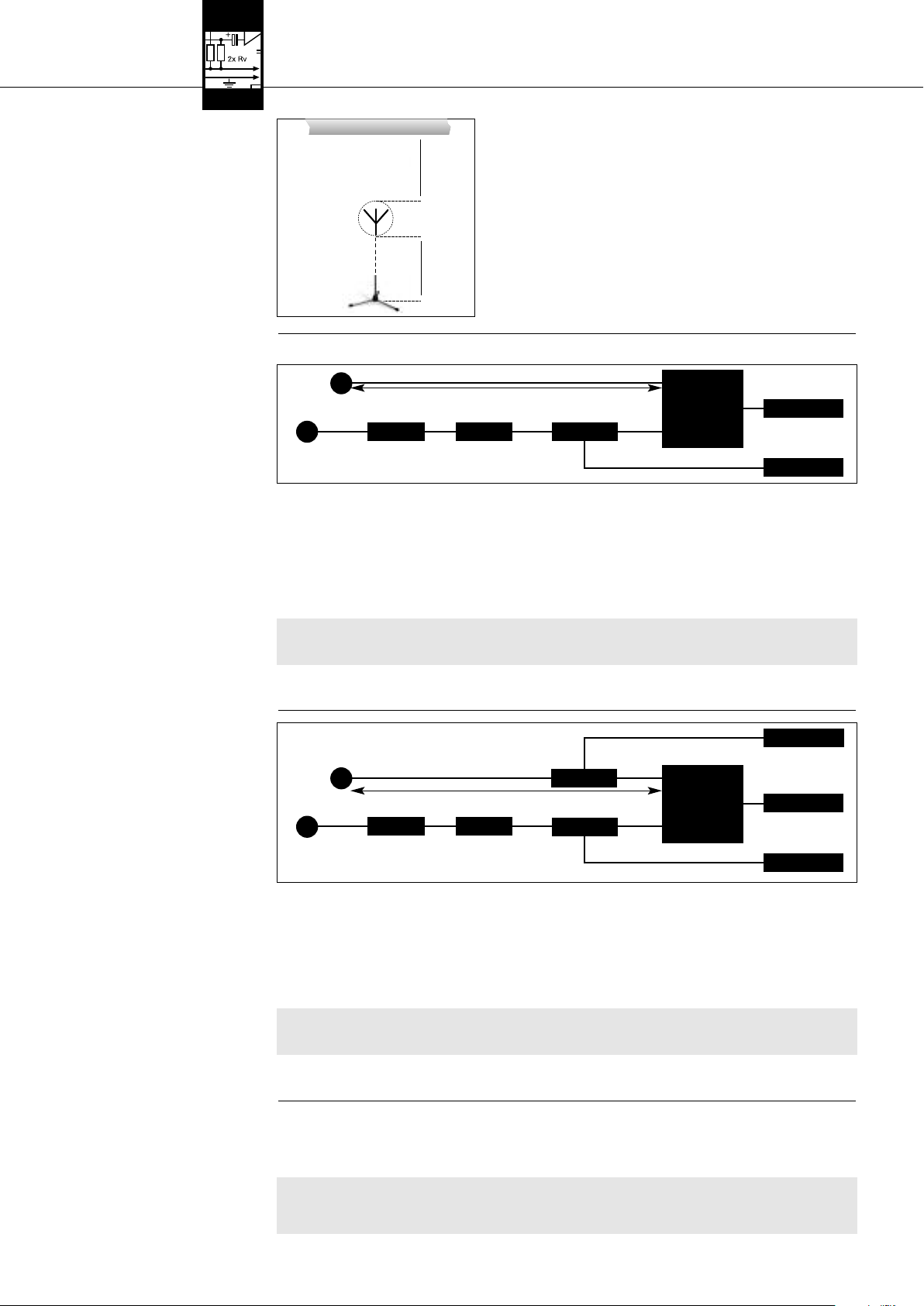
3 Mise en service
Fig. 5 : Distance minimum du sol
33..44 RRaaccccoorrddeemmeenntt ddeess aanntt eennnneess
33..44..11 IInnssttaallllaattiioonn mmoonnooccaannaall
aavveecc aanntteennnneess ppaassssiivveess
Voir Tableau 1, page 26 et Fig. 6
F
:
Câblage d'une installation monoca-
ig. 6
nal avec antennes passives et différentes
et du plafond
longueurs de câble
Voir Fig. 6.
˛
≥ 50 (15) cm
˛
˛
≥ 15cm
˛
Sur une installation monocanal vous n’avez pas besoin de splitter. Vous pouvez raccorder les antennes directement au récepteur.
Antenne
AA BB BB
Antenne
AA::
RG58: 0 - 13 m / RG213: 5 - 26 m
BB::
RG58: 6 - 46 m / RG213: 12 - 97 m
1. Mesurez la longueur de câble nécessaire entre le récepteur et les deux antennes.
2. Consultez le Tableau 1, page 26 pour voir si vous avez besoin de plusieurs câbles pour surmonter cette distance et s’il vous faut
un ou deux amplificateurs d’antenne AB 4000. Le Tableau 1 indique la longueur de câble maximale autorisée suivant le type de
câble.
3. Branchez un câble d’antenne sur chaque antenne.
4. Reliez les deux câbles d’antenne aux entrées d’antenne du récepteur comme indiqué au Tableau 1.
Si vous avez besoin d’un ou deux amplificateurs d’antenne AB 4000, il vous sera indispensable d’insérer une alimentation à distance ASU 4000 sur le câble entre le récepteur et le premier amplificateur d’antenne.
RG58: 0 - 13 m / RG213: 5 - 26 m
AABB 44000000
2. Veillez à ce que l’antenne se trouve à une distance minimum de 15 cm du sol ou
50 cm du plafond (15 cm si le câble arrive par le haut).
<<-- DDCC//AACC -->>
<<-- DDCC//AACC -->>
AABB 44000000
RRéécceepptteeuurr
AASSUU 44000000
Important !
33..44..22 IInnssttaallllaattiioonn mmoonnooccaannaall
aavv eecc aanntteennnneess aaccttiivveess
Voir Tableau 1, page 26 et Fig. 7
Câblage d'une installation monoca-
Fig. 7:
nal avec antennes actives et différentes
longueurs de câble.
Voir Fig. 7.
Important !
5. Vérifiez si la tension secteur indiquée sur les blocs secteurs de l’ASU 4000 et du récepteur concorde avec la tension
!
L
!
L
secteur sur le lieu d’utilisation. Le fonctionnement sur une tension secteur différente risquerait d’endommager les
blocs secteur.
6. Connectez l’alimentation à distance et le récepteur aux blocs secteur correspondants et branchez chaque bloc secteur sur une
prise secteur appropriée.
SRA 2 B/W
RG58: 0 - 13 m / RG213: 5 - 26 m
AABB 44000000
AA BB BB
SRA 2 B/W
1. Mesurez la longueur de câble nécessaire entre le récepteur et les deux antennes actives.
2. Consultez le Tableau 1, page 26 pour voir si vous avez besoin de plusieurs câbles pour surmonter cette distance et s’il vous faut
3. Branchez un câble d’antenne sur chaque antenne.
4. Reliez les deux câbles d’antenne, comme indiqué au Tableau 1, à un ou deux amplificateurs d’antenne AB 4000, à une alimen-
5. Vérifiez si la tension secteur indiquée sur les blocs secteurs des deux ASU 4000 et du récepteur concorde avec la ten-
6. Reliez les deux alimentations à distance et le récepteur aux blocs secteur correspondants et branchez chaque bloc secteur sur
AA::
RG58: 0 - 13 m / RG213: 5 - 26 m
BB::
RG58: 6 - 46 m / RG213: 12 - 97 m
un ou deux amplificateurs d’antenne AB 4000. Le Tableau 1 indique la longueur de câble maximale autorisée suivant le type de
câble.
tation à distance ASU 4000 chaque et aux entrées d’antenne du récepteur.
sion secteur sur le lieu d’utilisation. En les utilisant sur une tension secteur différente, vous risquez des dégâts sur
l’installation.
une prise secteur appropriée.
AABB 44000000 AASSUU 44000000
AASSUU 44000000
RRéécceepptteeuurr
<<-- DDCC//AACC -->>
<<-- DDCC//AACC -->>
<<-- DDCC//AACC -->>
33..55 IInnssttaallllaattiioonnss mmuullttiiccaannaauuxx
aavveecc sspplliitttteerr dd’’aanntteennnnee PPSS 44000000 WW
Attention !
Vous trouverez des exemples de câblage pour installations multicanaux aux Fig. 10 à 13, page 56.
Lorsque vous configurez une installation multicanaux, veuillez tenir compte des points suivants :
1. Vous pouvez raccorder jusqu’à quatre récepteurs sur le splitter PS 4000 W.
• Si vous faites fonctionner le splitter d’antenne ainsi que les récepteurs sur le bloc secteur fourni avec chacun, il faut
!
L
impérativement brancher sur le secteur d’abord les blocs secteur des récepteurs et en second lieu le bloc secteur du
splitter d’antenne. Si vous commencez par brancher le splitter, la charge que représentent les récepteurs risque d’endommager le bloc secteur du splitter.
24 AKG PS 4000 W
Page 25

3 Mise en service
2. Pour les g
3. Chaque entrée d’antenne du splitter peut alimenter au maximum trois composants actifs (p.ex. RA 4000 B/W + 2 x AB 4000)
Le niveau de signal HF sur chaque entrée d’antenne du (des) splitter(s) d’antenne dépend de la bande de fréquences, du type d’antenne, du type de câble et le la longueur du câble.
Pour être sûr d’avoir le niveau de signal HF optimal sur l’entrée d’antenne, réglez le commutateur CLA sur chaque amplificateur
d’antenne de même que sur le(s) splitter(s) comme indiqué au Tableau 1.
1. Otez la plaque du commutateur CLA.
2. Réglez les trois commutateurs DIP en fonction de la bande de fréquences, du type d’antenne, du type de câble et le la longueur
3. Remettez la plaque en place.
rosses installations comptant jusqu’à 50 canaux, vous pouvez relier ensemble un nombre de splitters d’antenne cor-
respondants :
• Reliez les embases LINK du premier splitter aux embases ANTENNA IN du splitter suivant et ainsi de suite.
• Pour alimenter de telles installations nous conseillons d’utiliser l’alimentation centrale optionnelle PSU 4000, à raison d’un
PSU 4000 pour trois splitters et quatre récepteurs.
via le câble d’antenne.
Dans les cas suivants vous aurez besoin d’une alimentation à distance ASU 4000 pour les composants actifs (l’ASU 4000 peut
également alimenter trois composants actifs) :
• La longueur de câble nécessaire entre le splitter et les composants actifs est telle que la tension d’alimentation tombe audessous de la valeur minimum admise.
• Un appareil (p.ex. combinateur* d’antennes) intercalé entre le PS 4000 W et les composants actifs interrompt l’alimentation
en c.c. dans le câble d’antenne.
* Le combinateur d’antennes ZAPD 21 de la société Mini Circuit laisse passer la tension d’alimentation, ce qui n’est généra-
lement pas le cas pour les autres produits.
• Vous avez connecté deux câbles d’antenne sur une entrée d’antenne à l’aide d’un combinateur d’antennes. Si vous utilisez
un câble d’antenne pour trois ou plusieurs composants actifs, intercalez une alimentation à distance ASU 4000 entre le combinateur et le premier de ces composants actifs. Si vous avez au total plus de trois composants actifs pour les deux câbles
d’antenne, vous aurez besoin d’une alimentation à distance ASU 4000 pour chaque câble. L’alimentation à distance est
nécessaire pour éviter une surcharge de l’alimentation du splitter d’antenne.
du câble.
RReemmaarrqquuee ::
33..66 CCoommmmuuttaatteeuurr CCLLAA
Voir Tableau 1, page 26
AKG PS 4000 W 25
Page 26

3 Mise en service
A
CLA
A B
CLA
A
CLA
CLA
B B
CLA
CLA
CLA
ON
1 2 3
14 dB
12 dB
10 dB
8 dB
6 dB
4 dB
2 dB
0 dB
RG58 RG213 CLA RG58 RG213 CLA RG58 RG213 CLA
53 - 57 111 - 121 0 38 - 43 79 - 89 0 41 - 46 87 - 97 0
48 - 53 100 - 111 2 33 - 38 68 - 79 2 36 - 41 76 - 87 2
43 - 48 89 - 100 4 28 - 33 58 - 68 4 31 - 36 66 - 76 4
38 - 43 79 - 89 6 23 - 28 47 - 58 6 26 - 31 55 - 66 6
GAMME I + IIGAMME III + IVGAMME V + VI
33 - 38 68 - 79 8 18 - 23 37 - 47 8 21 - 26 45 - 55 8
28 - 33 58 - 68 10 13 - 18 26 - 37 10 16 - 21 34 - 45 10
23 - 28 47 - 58 12 8 - 13 16 - 26 12 11 - 16 24 - 34 12
18 - 23 37 - 47 14 3 - 8 5 - 16 14 6 - 11 13 - 24 14
RG58 RG213 CLA RG58 RG213 CLA RG58 RG213 CLA RG58 RG213 CLA
50 - 55 105 - 115 0 36 - 40 75 - 85 0 7 - 12 15 - 25 0 39 - 44 83 - 93 0
45 - 50 95 - 105 2 31 - 36 65 - 75 2 2 - 7 5 - 15 2 35 - 39 73 - 83 2
40 - 45 85 - 95 4 26 - 31 55 - 65 4 0 - 2 4 30 - 35 63 - 73 4
36 - 40 75 - 85 6 21 - 26 45 - 55 6625 - 30 53 - 63 6
31 - 36 65 - 75 8 17 - 21 35 - 45 8820 - 25 43 - 53 8
26 - 31 55 - 65 10 12 - 17 25 - 35 10 10 15 - 20 33 - 43 10
21 - 26 45 - 55 12 7 - 12 15 - 25 12 12 11 - 15 23 - 33 12
17 - 21 35 - 45 14 2 - 7 5 - 15 14 14 6 - 11 13 - 23 14
RG58 RG213 CLA RG58 RG213 CLA RG58 RG213 CLA RG58 RG213 CLA
47 - 51 100 - 110 0 33 - 38 71 - 81 0 7 - 11 14 - 24 0 37 - 41 79 - 88 0
42 - 47 90 - 100 2 29 - 33 62 - 71 2 2 - 7 5 - 14 2 32 - 37 69 - 79 2
38 - 42 81 - 90 4 24 - 29 52 - 62 4 0 - 2 4 28 - 32 60 - 69 4
34 - 38 71 - 81 6 20 - 24 43 - 52 6623 - 28 50 - 60 6
29 - 34 62 - 71 8 16 - 20 33 - 43 8819 - 23 40 - 50 8
24 - 29 52 - 62 10 11 - 16 24 - 33 10 10 14 - 19 31 - 40 10
20 - 24 43 - 52 12 7 - 11 14 - 24 12 12 10 - 14 21 - 31 12
16 - 20 33 - 43 14 2 - 7 5 - 14 14 14 6 - 10 12 - 21 14
RG58 RG213 CLA RG58 RG213 CLA RG58 RG213 CLA
56 - 60 132 - 140 0 44 - 46 102 - 108 0 49 - 50 110 - 118 0
51 - 56 120 - 132 2 40 - 44 93 - 102 2 47 - 49 100 - 110 2
46 - 51 108 - 120 4 36 - 40 84 - 93 4 42 - 47 90 - 100 4
41 - 46 97 - 108 6 32 - 36 75 - 84 6 36 - 42 81 - 90 6
GAMME VII
36 - 41 83 - 97 8 28 - 32 66 - 75 8 31 - 36 70 - 81 8
31 - 36 71 - 83 10 25 - 28 57 - 66 10 27 - 31 60 - 70 10
26 - 31 60 - 71 12 21 - 25 48 - 57 12 23 - 27 50 - 60 12
23 - 26 52 - 60 14 18 - 21 42 - 48 14 19 - 23 44 - 50 14
RG58 RG213 CLA RG58 RG213 CLA RG58 RG213 CLA
53 - 56 122 - 131 0 40 - 44 94 - 101 0 43 - 46 102 - 107 0
48 - 53 110 - 122 2 35 - 40 82 - 94 2 38 - 43 88 - 102 2
43 - 48 99 - 110 4 30 - 35 70 - 82 4 33 - 38 76 - 88 4
38 - 43 88 - 99 6 25 - 30 58 - 70 6 28 - 33 64 - 76 6
GAMME VIII
33 - 38 79 - 88 8 22 - 25 46 - 58 8 23 - 28 52 - 64 8
28 - 33 63 - 74 10 16 - 22 34 - 46 10 18 - 23 40 - 52 10
23 - 28 50 - 63 12 11 - 16 22 - 34 12 13 - 18 28 - 40 12
20 - 23 43 - 50 14 7 - 11 15 - 22 14 10 - 13 20 - 28 14
SRA 2 B/W RA 4000 B/W
(m) (m) (dB) (m) (m) (dB) (m) (m) (dB)
SRA 2 B/W RA 4000 B/W
(m) (m) (dB) (m) (m) (dB) (m) (m) (dB) (m) (m) (dB)
SRA 2 B/W RA 4000 B/W
(m) (m) (dB) (m) (m) (dB) (m) (m) (dB) (m) (m) (dB)
SRA 2 B/W RA 4000 B/W
(m) (m) (dB) (m) (m) (dB) (m) (m) (dB)
SRA 2 B/W RA 4000 B/W
(m) (m) (dB) (m) (m) (dB) (m) (m) (dB)
A
A
A
A
A
Tableau 1 : Positions des commutateurs DIP CLA en fonction de la bande de fréquences, du type d’antenne, du type et de la longueur du câble.
B
B
B
B
B
26 AKG PS 4000 W
Page 27

4 Instructions pour le fonctionnement
1. Faites attention à bien choisir pour chaque canal d’émission (émetteur + récepteur) une fréquence propre.
2. N’utilisez jamais plus
ceci aurait des parasites bruyants pour conséquence.
• Pour mettre l’installation sous tension et hors tension, procédez impérativement dans l’ordre indiqué aux points 4.2 et
4.3 afin d’éviter toute détérioration due à une surcharge de l’alimentation du splitter d’antenne.
1. Mettez les émetteurs sous tension.
2. Mettez tous les récepteurs connectés au splitter d’antenne sous tension.
3. Mettez le splitter d’antenne sous tension en appuyant sur la touche ON/OFF.
Les LED OK bleues du splitter ainsi que les voyants verts des composants actifs connectés s’allument.
1. Mettez tous les récepteurs connectés au splitter d’antenne hors tension.
2. Mettez les émetteurs hors tension.
3. Mettez le splitter d’antenne hors tension en appuyant sur la touche ON/OFF.
Les LED OK bleues du splitter ainsi que les voyants verts des composants actifs connectés s’éteignent.
1. Mettez l’alimentation centrale optionnelle PSU 4000 sous tension.
2. Mettez les émetteurs sous tension.
3. Mettez le splitter d’antenne sous tension en appuyant sur la touche ON/OFF.
Les LED OK bleues du splitter ainsi que les voyants verts des composants actifs connectés s’allument.
4. Mettez tous les récepteurs connectés au splitter d’antenne sous tension.
1. Mettez tous les récepteurs connectés au splitter d’antenne hors tension.
2. Mettez les émetteurs hors tension.
3. Mettez le splitter d’antenne hors tension en appuyant sur la touche ON/OFF.
Les LED OK bleues du splitter ainsi que les voyants verts des composants actifs connectés s’éteignent.
4. Mettez l’alimentation centrale optionnelle PSU 4000 hors tension.
d’un canal d’émission à la fois en un même lieu sur une même fréquence. En raison des lois physiques,
44..11 GGéénnéérraalliittééss
IImmppoorrttaanntt !!
!
L
44..22 IInnssttaallllaattiioonnss aavveecc aalliimmeennttaattiioonn
ddéécceennttrraalliissééee
44..22..11 MMiissee ssoouuss tteennssiioonn
44..22..22 MMiissee hhoorrss tteennssiioonn
44..33 IInnssttaallllaattiioonnss aavveecc aalliimmeennttaattiioonn
cceennttrr aallee ooppttiioonnnneellllee PPSSUU 44000000
44..33..11 MMiissee ssoouuss tteennssiioonn
44..33..22 MMiissee hhoorrss tteennssiioonn
5 Nettoyage
• Pour nettoyer la surface du splitter d’antenne, utilisez un chiffon souple légèrement humecté d’eau.
6 Dépannage
Problème Cause possible Remède
PPaass ddee ssoonn..
PPaass ddee rréécceeppttiioonn oouu rréécceeppttiioonn ppeerrttuurrbbééee
ssuurr cceerrttaaiinnss ccaannaauuxx ::
1. Les blocs secteurs/le PSU 4000 ne sont pas branchés
sur le secteur.
2. Les câbles c.c. ne sont pas connectés ou sont défectueux.
3. Les antennes ne sont pas connectées.
4. Le(s) bloc(s) secteur/le PSU 4000 sont défectueux.
1. L’émetteur et/ou le récepteur ne sont pas sous tension.
2. Les piles de l’émetteur sont épuisées.
3. Le bloc secteur du récepteur ou le câble de liaison du
PSU 4000 sur le récepteur
a) a un mauvais contact ou
b) est défectueux.
4. L’émetteur et le récepteur du canal considéré ne sont
pas réglés sur la même fréquence.
5. Emetteur ou récepteur défectueux.
1. Brancher les blocs secteurs/le PSU 4000 sur une
prise secteur.
2. Connecter ou remplacer les câbles c.c.
3. Connecter les antennes.
4. Contacter le S.A.V. d’AKG.
1. Mettre l’émetteur et/ou le récepteur sous tension.
2. Remplacer les piles de l’émetteur.
3. a) Vérifier si la fiche du bloc secteur ou du câble de
liaison est bien enfoncée ou
b) remplacer le bloc secteur ou le câble de liaison.
4. Régler émetteur et récepteur sur la même fréquence.
Pour ce faire, veuillez consulter la notice d’emploi de
l’émetteur et du récepteur.
5. Contactez votre revendeur AKG.
LLaa LLEEDD vveerrttee dd’’uunn ccoomm ppoossaanntt aaccttiiff
nnee ss’’aalllluummee ppaass..
UUnnee LLEEDD EERRRROORR dduu sspplliitttteerr ss’’aalllluummee..
1. Le câble d’antenne n’est pas connecté ou a un mauvais contact.
2. Câble d’antenne défectueux.
3. Composants actifs défectueux.
1. La tension d’alimentation des composants d’antenne
actifs est court-circuitée.
2. La tension d’alimentation des composants d’antenne
actifs est insuffisante en raison d’une longueur excessive du câble.
1. Connecter le câble d’antenne ou vérifier si le connecteur est bien enfoncé.
2. Remplacer le câble d’antenne.
3. Contacter le S.A.V. d’AKG.
1. Contrôler tous les câbles et composants actifs
connectés. Remplacer les câbles et/ou composants
actifs défectueux.
2. Contrôler à l’aide du Tableau 1 la longueur des câbles
connectés ; utiliser un câble plus court ou mettre plusieurs câbles courts bout à bout et ajouter un ASU
4000 (cf. diagrammes de câblage).
AKG PS 4000 W 27
Page 28

7 Caractéristiques techniques
Splitter d’antenne PS 4000 W
Type : 2 x 1 sur 4 récepteurs + 2 x 1 PS (possibilité de cascader)
Gamme de fréquences porteuses : 500 - 865 MHz
Atténuation : 0, 2, 4, 6, 8, 10, 12, 14 dB, commutable
Entrées HF : 2 embases BNC, 50 Ohms
Sorties HF : 10 embases BNC, 50 Ohms
Tension d’alimentation : 12 V c.c.
Dimensions : 200 x 190 x 44 mm
Poids : 970 g env.
Amplificateur d’antenne AB 4000
Gamme de fréquences porteuses : 500 - 865 MHz
Amplification : 17 - 3,5 dB env., commutable
Entrée HF : 1 embase BNC, 50 Ohms
Sortie HF : 1 embase BNC, 50 Ohms
Tension d’alimentation : 8 V c.c. via le câble d’antenne du PS 4000 W ou ASU 4000
Dimensions : 110 x 35 mm
Poids : 150 g env.
Antenne amplifiée omnidirectionnelle RA 4000 B/W
Gamme de fréquences porteuses : 500 - 865 MHz
Gain + amplification : 17 dB
Entrée HF : 1 embase BNC, 50 Ohms
Sortie HF : 1 embase BNC, 50 Ohms
Tension d’alimentation : 8 V c.c. via le câble d’antenne du PS 4000 W ou ASU 4000
Dimensions : 235 x 38,5 mm
Poids : 65 g
Antenne directive passive SRA 2 B/W
Gamme de fréquences porteuses : 500 - 865 MHz
Gain + amplification : 21,5 dB env.
Ouverture : 70°
Dimensions : 230 x 240 x 26 mm
Poids : 250 g env.
Alimentation à distance ASU 4000
Gamme de fréquences porteuses : 500 - 865 MHz
Entrée HF : 1 embase BNC, 50 Ohms
Sortie HF : 1 embase BNC, 50 Ohms
Tension d’alimentation : 12 V c.c.
Dimensions : 78 x 50 x50 mm
Poids : 150 g env.
Ce produit est conforme aux normes citées dans la Déclaration de Conformité, dont vous pouvez prendre connaissance en consultant le site http://www.akg.com ou en adressant
un e-mail à sales@akg.com.
28 AKG PS 4000 W
Page 29

Indice
1 Sicurezza ed ambiente . . . . . . . . . . . . . . . . . . . . . . . . . . . . . . . . . . . . . . . . . . . . . . . . . . . . . . . . . . . . . . . . . 29
1.1 Sicurezza
1.2 Ambiente. . . . . . . . . . . . . . . . . . . . . . . . . . . . . . . . . . . . . . . . . . . . . . . . . . . . . . . . . . . . . . . . . . . . . . . . 29
2 Descrizione . . . . . . . . . . . . . . . . . . . . . . . . . . . . . . . . . . . . . . . . . . . . . . . . . . . . . . . . . . . . . . . . . . . . . . . . . . 30
2.1 Introduzione. . . . . . . . . . . . . . . . . . . . . . . . . . . . . . . . . . . . . . . . . . . . . . . . . . . . . . . . . . . . . . . . . . . . . . 30
2.2 In dotazione . . . . . . . . . . . . . . . . . . . . . . . . . . . . . . . . . . . . . . . . . . . . . . . . . . . . . . . . . . . . . . . . . . . . . . 30
2.3 Accessori opzionali. . . . . . . . . . . . . . . . . . . . . . . . . . . . . . . . . . . . . . . . . . . . . . . . . . . . . . . . . . . . . . . . . 30
2.4 Descrizione . . . . . . . . . . . . . . . . . . . . . . . . . . . . . . . . . . . . . . . . . . . . . . . . . . . . . . . . . . . . . . . . . . . . . . 30
2.5 Alimentatore centrale PSU 4000 (opzionale) . . . . . . . . . . . . . . . . . . . . . . . . . . . . . . . . . . . . . . . . . . . . . . 31
2.6 Antenne di ricezione (opzionali) . . . . . . . . . . . . . . . . . . . . . . . . . . . . . . . . . . . . . . . . . . . . . . . . . . . . . . . . 31
3 Messa in esercizio . . . . . . . . . . . . . . . . . . . . . . . . . . . . . . . . . . . . . . . . . . . . . . . . . . . . . . . . . . . . . . . . . . . . 32
3.1 Montaggio di uno splitter d’antenna in un rack . . . . . . . . . . . . . . . . . . . . . . . . . . . . . . . . . . . . . . . . . . . . 32
3.2 Montaggio di due splitter d’antenna in un rack, uno accanto all’altro . . . . . . . . . . . . . . . . . . . . . . . . . . . . 32
3.3 Come posizionare le antenne . . . . . . . . . . . . . . . . . . . . . . . . . . . . . . . . . . . . . . . . . . . . . . . . . . . . . . . . . 32
3.4 Come collegare le antenne . . . . . . . . . . . . . . . . . . . . . . . . . . . . . . . . . . . . . . . . . . . . . . . . . . . . . . . . . . . 33
3.5 Impianti pluri-canale con splitter d’antenna PS 4000 W . . . . . . . . . . . . . . . . . . . . . . . . . . . . . . . . . . . . . . 33
3.6 Interruttore CLA . . . . . . . . . . . . . . . . . . . . . . . . . . . . . . . . . . . . . . . . . . . . . . . . . . . . . . . . . . . . . . . . . . . 34
4 Indicazioni per l’esercizio . . . . . . . . . . . . . . . . . . . . . . . . . . . . . . . . . . . . . . . . . . . . . . . . . . . . . . . . . . . . . . 36
4.1 Indicazioni generali. . . . . . . . . . . . . . . . . . . . . . . . . . . . . . . . . . . . . . . . . . . . . . . . . . . . . . . . . . . . . . . . . 36
4.2 Impianti con alimentatori decentrali . . . . . . . . . . . . . . . . . . . . . . . . . . . . . . . . . . . . . . . . . . . . . . . . . . . . . 36
4.3 Impianti con alimentatore centrale opzionale PSU 4000 . . . . . . . . . . . . . . . . . . . . . . . . . . . . . . . . . . . . . . 36
. . . . . . . . . . . . . . . . . . . . . . . . . . . . . . . . . . . . . . . . . . . . . . . . . . . . . . . . . . . . . . . . . . . . . . . . 29
2.4.1 Pannello frontale . . . . . . . . . . . . . . . . . . . . . . . . . . . . . . . . . . . . . . . . . . . . . . . . . . . . . . . . . . . . . . 30
2.4.2 Lato posteriore . . . . . . . . . . . . . . . . . . . . . . . . . . . . . . . . . . . . . . . . . . . . . . . . . . . . . . . . . . . . . . . 31
2.6.1 SRA 2 B/W . . . . . . . . . . . . . . . . . . . . . . . . . . . . . . . . . . . . . . . . . . . . . . . . . . . . . . . . . . . . . . . . . . 31
2.6.2 RA 4000 B/W . . . . . . . . . . . . . . . . . . . . . . . . . . . . . . . . . . . . . . . . . . . . . . . . . . . . . . . . . . . . . . . . 31
3.3.1 Luogo di posizionamento . . . . . . . . . . . . . . . . . . . . . . . . . . . . . . . . . . . . . . . . . . . . . . . . . . . . . . . . 32
3.3.2 Montaggio su supporto da pavimento. . . . . . . . . . . . . . . . . . . . . . . . . . . . . . . . . . . . . . . . . . . . . . . 32
3.3.3 Montaggio su parete/soffitto . . . . . . . . . . . . . . . . . . . . . . . . . . . . . . . . . . . . . . . . . . . . . . . . . . . . . 32
3.4.1 Impianto mono-canale con antenne passive . . . . . . . . . . . . . . . . . . . . . . . . . . . . . . . . . . . . . . . . . . 33
3.4.2 Impianto mono-canale con antenne attive . . . . . . . . . . . . . . . . . . . . . . . . . . . . . . . . . . . . . . . . . . . 33
4.2.1 Attivazione . . . . . . . . . . . . . . . . . . . . . . . . . . . . . . . . . . . . . . . . . . . . . . . . . . . . . . . . . . . . . . . . . . 36
4.2.2 Disattivazione . . . . . . . . . . . . . . . . . . . . . . . . . . . . . . . . . . . . . . . . . . . . . . . . . . . . . . . . . . . . . . . . 36
4.3.1 Attivazione . . . . . . . . . . . . . . . . . . . . . . . . . . . . . . . . . . . . . . . . . . . . . . . . . . . . . . . . . . . . . . . . . . 36
4.3.2 Disattivazione . . . . . . . . . . . . . . . . . . . . . . . . . . . . . . . . . . . . . . . . . . . . . . . . . . . . . . . . . . . . . . . . 36
5 Pulizia . . . . . . . . . . . . . . . . . . . . . . . . . . . . . . . . . . . . . . . . . . . . . . . . . . . . . . . . . . . . . . . . . . . . . . . . . . . . . . 36
6 Errori e rimedi. . . . . . . . . . . . . . . . . . . . . . . . . . . . . . . . . . . . . . . . . . . . . . . . . . . . . . . . . . . . . . . . . . . . . . . . 36
7 Dati tecnici . . . . . . . . . . . . . . . . . . . . . . . . . . . . . . . . . . . . . . . . . . . . . . . . . . . . . . . . . . . . . . . . . . . . . . . . . . 37
Figg. 8 a 13. . . . . . . . . . . . . . . . . . . . . . . . . . . . . . . . . . . . . . . . . . . . . . . . . . . . . . . . . . . . . . . . . . . . . . . . . . . . . 56
1 Sicurezza ed ambiente
1. Non versate liquidi sull'apparecchio e non fate cadere oggetti nell'apparecchio attraverso le fessure di ventilazione.
2. L’apparecchio deve venir impiegato solo in vani asciutti.
3. L’apparecchio deve venir aperto, mantenuto e riparato solo da personale specializzato autorizzato. All’interno della scatola non
vi sono componenti che possano venir mantenuti, riparati o sostituiti da non professionals.
4. Prima di mettere in esercizio l’apparecchio controllate se la tensione d’esercizio indicata sull’alimentatore in dotazione corrisponde alla tensione di rete del luogo d’impiego.
5. Fate funzionare l’apparecchio esclusivamente con l’alimentatore in dotazione, con una tensione d’uscita di 12 V c.c. Altri tipi di
corrente e di tensione possono danneggiare seriamente l’apparecchio!
6. Interrompete subito il funzionamento dell’impianto quando un corpo solido o liquidi entrano nell’apparecchio. Sfilate in questo
caso subito l’alimentatore dalla presa e fate controllare l’apparecchio dal nostro reparto service clienti.
7. Quando non usate l’apparecchio per più tempo, sfilate l’alimentatore dalla presa. Tenete presente che quando l’alimentatore è
inserito nella presa l’apparecchio – anche quando è spento - non è completamente staccato dalla rete.
8. Non posizionate l'apparecchio nella vicinanza di fonti di calore, come p.e. radiatori, tubi del riscaldamento o amplificatori ecc., e
non esponetelo direttamente al sole, alla polvere e all'umidità, alla pioggia, a vibrazioni o a colpi.
9. Per evitare disturbi, posate tutte le linee, specialmente quelle degli ingressi microfonici, separate dalle linee a corrente forte e
linee di rete. In caso di posa in pozzi o canali per cavi fate attenzione a posare le linee di trasmissione in un canale separato.
10. Pulite l’apparecchio solo con un panno umido, ma non bagnato. Dovete assolutamente sfilare prima l’alimentatore dalla presa!
Non usate in nessun caso detergenti acidi o abrasivi o detergenti contententi alcool o solventi perché potrebbero danneggiare la
vernice e i componenti in materia sintetica.
11. Usate l'apparecchio solo per gli impieghi descritti nelle presenti istruzioni per l’uso. La AKG non assume nessuna responsabilità per danni causati da manipolazione non effettuata a regola d’arte o da uso non corretto.
!
L
11..11 SSiiccuurreezzzzaa
1. L’alimentatore assorbe una piccola quantità di corrente anche quando l’apparecchio è spento. Per risparmiare energia sfilate
quindi l’alimentatore dalla presa se non lo usate per più tempo.
2. Se rottamate l’apparecchio, togliete le batterie risp. gli accumulatori, separate scatola, elettronica e cavi e smaltite tutti i componenti conformemente alle norme di smaltimento vigenti per essi.
3. L'imballaggio è riciclabile. Smaltite l'imballaggio in un apposito sistema di raccolta.
AKG PS 4000 W 29
11..22 AAmmbbiieennttee
Page 30
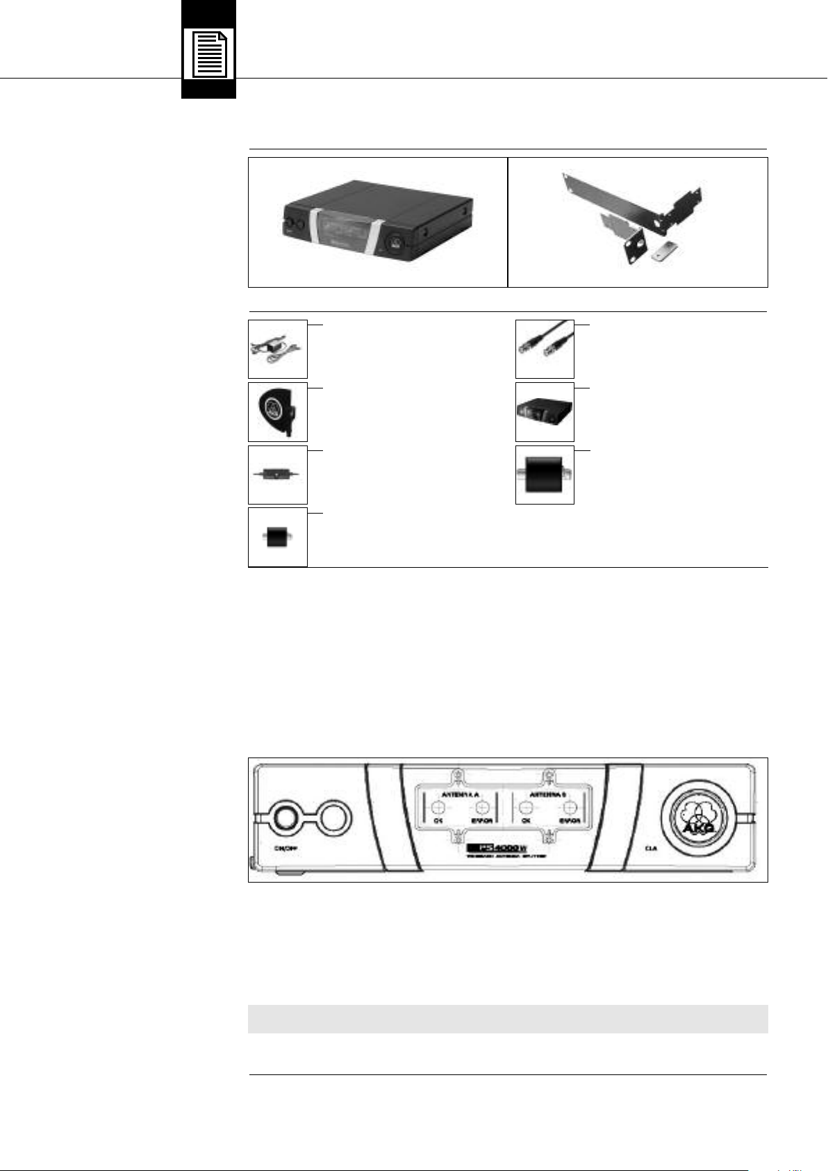
2 Descrizione
22..11 II nnttrroodduuzziioonnee
22..22 II nn ddoottaazziioonnee
22..33 AAcccceessssoorrii ooppzziioonnaallii
Vi ringraziamo di aver scelto un prodotto della AKG. Leggete attentamente le presenti istruzioni per l’uso prima di usare l’apparecchio e tenete sempre a mano le istruzioni per poterle consultare in qualsiasi momento. Vi auguriamo buon divertimento e suc-
cesso!
1 Antennensplitter PS 4000 W 1 19"-Montageset
Controllate per favore se la confezione contiene tutti i componenti indicati. Se manca qualcosa, rivolgetevi al vostro rivenditore AKG.
• Alimentatore 12 V c.c.
• Antenna direzionale attiva SRA 2 B/W
• Antenna onnidirezionale attiva
RA 4000 B/W
• Amplificatore d’antenna AB 4000
• Cavi d’antenna MK PS
• Alimentatore centrale PSU 4000
• Alimentatore a distanza ASU 4000
22..44 DDeessccrriizziioonnee
22..44..11 PPaannnneelllloo ffrroonnttaallee
Fig. 1: Pannello frontale del PS 4000 W
Lo splitter d’antenna PS 4000 W è un distributore d’antenna per configurare un sistema pluri-canale URF con fino a 4 ricevitori per
ogni splitter d’antenna (il numero effettivo di canali che potranno essere gestiti contemporaneamente dipende dal piano di frequenza del paese dove vengono impiegati).
Il PS 4000 W è dotato di due prese d’ingresso d’antenna a cui potete collegare le antenne di ricezione attive SRA 2 B/W o
RA 4000 B/W con booster incorporato (amplificatore d’antenna). Gli ingressi d’antenna forniscono una tensione di alimentazione di
12 V c.c. per al massimo tre componenti d’antenna attivi, p.e. un’antenna attiva e due amplificatori d’antenna AB 4000. Sul lato
posteriore sono disposti inoltre 2 x 4 prese d’uscita d’antenna per fino a 4 ricevitori Diversity nonché due prese d’uscita d’antenna
addizionali per trasmettere il segnale d’antenna a più splitter d’antenna addizionali PS 4000 W.
Il PS 4000 W è dotato di una scatola metallica robusta di un’unità d’altezza e di mezza larghezza 19" in modo da poter montare due
splitter d’antenna in un livello di rack, uno accanto all’altro.
Il PS 4000 W viene alimentato da un’alimentatore opzionale. Per impianti con più di 4 canali raccomandiamo l’alimentatore centrale opzionale PSU 4000 per rispettivamente tre splitter d’antenna.
Sia gli amplificatori d’antenna che lo splitter d’antenna sono apparecchi a larga gamma, per l’intera gamma delle frequenze UHF.
Sul pannello frontale dello splitter d’antenna sono disposti i seguenti elementi di comando e le seguenti indicazioni:
ON/OFF: Tasto on/off. Per attivare l’apparecchio, premete questo tasto. Per disattivare l’apparecchio, premete di nuovo il tasto.
ANTENNA A, ANTENNA B: Il LED OK blu si accende quando alla presa d’ingresso d’antenna ANTENNA A IN/ANTENNA B IN è a dis-
posizione la corretta tensione di alimentazione per i componenti attivi.
Se la tensione di alimentazione di un ingresso d’antenna è cortocircuitata o viene a mancare (scendendo sotto i 2 V), il rispettivo LED OK si spegne e il LED rosso ERROR si accende.
NNoottaa::
• I due LED OK NON indicano lo stato d’esercizio del rispettivo amplificatore d’antenna e non si spengono quindi quando sfilate il
cavo d’antenna.
Vedi tabella 1 a pagina 35.
CLA: Sotto la copertura recante il logo dell’AKG è disposto un interruttore DIP a tre fasi, per adattare gli ingressi d’antenna (ANTEN-
NA A IN, ANTENNA B IN) alle diverse lunghezze dei cavi d’antenna.
30 AKG PS 4000 W
Page 31

Sul lato posteriore del PS 4000 W sono a disposizione i seguenti ingressi e le seguenti uscite:
2 Descrizione
22..44..22 LLaattoo ppoosstteerriioorree
Fig. 2: Lato posteriore del PS 4000 W
DC IN 12 V/2
ANTENNA A IN, ANTENNA B IN: Prese d’ingresso BNC per le antenne di ricezione staccate SRA 2 B/W o RA 4000 B/W. Quando
ANTENNA A OUT TO SR: Alle quattro prese d’uscita BNC 1A fino a 4A è a disposizione il segnale d’antenna per la parte ricevente
ANTENNA B OUT TO SR: Alle quattro prese d’uscita BNC 1B fino a 4B è a disposizione il segnale d’antenna per la parte ricevente
• La corrente alle prese d’uscita 1A fino a 4B è sufficiente per alimentare i ricevitori collegati solo se lo splitter d’an-
• Se gestite lo splitter d’antenna PS 4000 W con l’alimentatore in dotazione, dovete gestire anche tutti i ricevitori con
LINK A TO PS, LINK B TO PS: A queste prese d’uscita BNC è a disposizione il segnale RF delle due antenne A e B. Potete collega-
L’alimentatore centrale PSU 4000 fornisce una tensione secondaria di 12 V c.c., 2 A, per tre splitter d’antenna PS 4000 W ed i ricevitori ad essi collegati (al massimo 12). Per i dettagli, consultate le istruzioni per l’uso del PSU 4000.
Per il sistema d’antenna PS 4000 W sono a disposizione antenne direzionali passive ed attive, ed antenne onnidirezionali passive ed
attive. Tutte le antenne sono antenne a larga gamma, per l’intera gamma delle frequenze UHF.
Le antenne attive vengono alimentate dallo splitter d’antenna PS 4000 W, attraverso i cavi d’antenna. In caso di impianti complessi, con lunghi cavi d’antenna, raccomandiamo di gestire le antenne attive con l’alimentatore centrale PSU 4000, attraverso rispettivamente un alimentatore a distanza ASU 4000.
A: Presa d’ingresso per un’alimentatore 12 V c.c. (opzionale) oppure l’alimentatore centrale opzionale PSU 4000.
utilizzate ricevitori con tecnica Diversity, avete bisogno di due antenne di ricezione (non in dotazione). Le prese d’ingresso d’antenna forniscono una tensione di alimentazione di 12 V c.c. per le antenne attive.
A di fino a quattro ricevitori Diversity. Tutte le uscite non utilizzate vengono automaticamente chiuse elettricamente.
B di fino a quattro ricevitori Diversity. Tutte le uscite non utilizzate vengono automaticamente chiuse elettricamente.
Oltre al segnale d’antenna, le prese d’uscita 1A fino a 4A nonché 1B fino a 4B forniscono una tensione di alimentazione di 12
V c.c. per i ricevitori collegati.
tenna è collegato all’alimentatore centrale opzionale PSU 4000.
un alimentatore separato (in dotazione). Se collegate i ricevitori allo splitter d’antenna senza alimentatore, l’alimentatore dello splitter d’antenna potrà venir danneggiato a causa del sovraccarico.
re le prese LINK alle prese d’ingresso d’antenna di un ulteriore splitter d’antenna PS 4000 W collegando così in cascata parecchi splitter d’antenna.
Tenete per favore presente che per ogni tre splitter d’antenna PS 4000 W avete bisogno di un alimentatore centrale opzionale
PSU 4000.
IImmppoorrttaannttee!!
!
L
Vedi anche i diagrammi di cablaggio
figg. 10
a 13.
22..55 AAlliimmeennttaattoorree cceennttrraallee PPSSUU 44000000
((ooppzziioonnaallee))
22..66 AAnntteennnnee ddii rriicceezziioonnee
((ooppzziioonnaallii))
La SRA 2 B/W è un’antenna direzionale attiva, con una scatola robusta, stagna all’acqua, per l’impiego in edifici o all’aperto e si presta specialmente per il collocamento a distanze più grandi dalla zona d’azione. L’integrato amplificatore d’antenna ad alto rendimento
permette di posizionare l’antenna ad una distanza di fino a 100 m dal ricevitore. Con cavi d’antenna RG213 e due amplificatori d’antenna AB 4000 in serie potete posizionare la SRA 2 B/W persino ad una distanza di fino a 200 m dal ricevitore.
L’antenna è dotata di una presa d’uscita BNC, di un LED per il controllo della funzione e di un collegamento integrato per supporto.
La RA 4000 B/W è un’antenna onnidirezionale attiva con una scatola robusta, stagna all’acqua, per l’impiego in edifici o all’aperto
e si presta specialmente per il collocamento nelle immediate vicinanze della zona d’azione. L’integrato amplificatore d’antenna ad
alto rendimento permette di posizionare l’antenna ad una distanza di fino a 100 m dal ricevitore. Con cavi RG213 e 2 amplificatori
d’antenna AB 4000 in serie potete posizionare la RA 4000 B/W persino ad una distanza di fino a 200 m dal ricevitore.
L’antenna è dotata di una presa d’uscita BNC, di un LED per il controllo della funzione e di un collegamento integrato per supporto.
22..66..11 SSRRAA 22 BB//WW
22..66..22 RRAA 44000000 BB//WW
AKG PS 4000 W 31
Page 32

3 Messa in esercizio
33..11 CCoommee mmoonnttaarree uunnoo sspplliitttteerr
dd''aanntteennnnaa iinn uunn rraacckk
Vedi fig. 8.
33..22 CCoommee mmoonnttaarree dduuee sspplliitttteerr
dd''aanntteennnnaa iinn uunn rraacckk
Vedi fig. 9.
NNoottaa::
33..33 CCoommee ppoossiizziioonnaarree llee aanntteennnnee
33..33..11 LLuuooggoo ddii ppoossiizziioonnaammeennttoo
1. Svitate i quattro piedini in gomma (1) dal lato inferiore dello splitter d'antenna.
2. Svitate le due viti di fissaggio (2) da ognuna delle pareti laterali.
3. Con le viti (2), avvitate l’angolo di montaggio corto (3) su una parete laterale e l’angolo di montaggio lungo (4) sull’altra parete
laterale, scegliendoli dal set di montaggio RMU 40/div.
4. Fissate lo splitter d'antenna nel rack.
1. Svitate i quattro piedini in gomma (1) dal lato inferiore degli splitter d'antenna e togliete le viti (5) dai piedini in gomma (1).
2. Svitate le due viti di fissaggio (2) dalla parete laterale destra del primo splitter d'antenna e dalla parete laterale sinistra del secondo splitter d'antenna.
3. Sfilate le coperture in plastica (3) da quelle pareti laterali dalle quali non avete svitato le viti di fissaggio (2).
4. Inserite un elemento di collegamento (4) attraverso rispettivamente una fessura libera nella parete laterale del primo splitter d'antenna in modo che il foro di fissaggio di ambedue gli elementi di collegamento (4) sia allineato al foro di filettatura nella parte
inferiore dello splitter d'antenna.
5. Fissate i due elementi di collegamento (4) con due delle viti (5) (dei piedini in gomma) sul primo splitter d'antenna.
6. Collegate i due splitter d'antenna inserendo gli elementi di collegamento (4) del primo splitter d'antenna attraverso le fessure
libere nella parete laterale del secondo splitter d'antenna fin quando il foro di fissaggio dei due elementi di collegamento (4) sia
allineato con il corrispondente foro di filettatura nella parte inferiore del secondo splitter d'antenna.
7. Fissate gli elementi di collegamento (4) con due delle viti (5) dei piedini in gomma (1) sul secondo splitter d'antenna.
8. Avviate, con rispettivamente due delle viti (2) delle pareti laterali, rispettivamente un angolo di montaggio corto (6) sulla parete
laterale esterna di ogni splitter d'antenna.
9. Fissate gli splitter d'antenna nel rack.
• Conservate le restanti viti (5) per poterle utilizzare più tardi.
Le seguenti indicazioni relative al posizionamento delle antenne valgono per tutti gli impianti mono-canale nonché per impianti pluricanale, indipendentemente dal numero dei canali.
Le riflessioni del segnale del trasmettitore su parti metalliche, pareti e soffitti ecc. oppure le ombre prodotte dall‘interposizione del
corpo umano possono indebolire o spegnere il segnale diretto del trasmettitore. Posizionate quindi le antenne come segue:
1. Posizionate le antenne sempre nelle vicinanze del luogo d‘impiego (palco), facendo attenzione a mantenere una distanza minima tra trasmettitore e antenne di 5 m e una distanza minima tra le antenne di 20 cm.
2. Presupposto per una ricezione ottimale è il collegamento a vista tra trasmettitore e antenna.
3. Posizionate le antenne ad una distanza di più di 1,5 m da grandi oggetti metallici, filo metallico (in particolare reticolato) e lamiere, pareti, impalcature, soffitti e simili.
4. Non posizionate le antenne in nicchie.
5. Posizionate le antenne ad una distanza minima di 1,5 m da apparecchi emittenti radiazioni RF, come light racks, tubi luminescenti, apparecchi digitali per effetti acustici e PC.
6. Se posizionate due antenne una accanto all’altra (p.e. per ricezione diversity), fate attenzione che la distanza tra le antenne sia
di almeno 20 cm.
33..33..22 MMoonnttaaggggiioo ssuu ssuuppppoorrttoo
ddaa ppaavviimmeennttoo
Fig. 3: Antenna montata su supporto
da pavimento
33..33..33 MMoonnttaaggggiioo
ssuu ppaarreettee//ssooffffiittttoo
Fig. 4: Distanza minima da super fici piane
≥ 70c m
˛
˛
Se montate le antenne su supporti da pavimento, tenete presente le seguenti avvertenze:
1. Fissate l’antenna, per mezzo del collegamento per supporto SA 63 in dotazione,
˛
rispettivamente del collegamento integrato per supporto, all’asta di un supporto
a giraffa.
2. Tirate l’asta completamente da un lato, in modo che l’antenna si trovi ad una
distanza di almeno 70 cm dal supporto.
≥ 180cm
3. Allungate il supporto fin quando l’asta si trova almeno 1,8 m sopra il suolo.
4. Arrotolate il cavo d’antenna intorno all’asta. Il cavo non deve pendere giù perché
in tal modo potrebbe pregiudicare la qualità di ricezione.
˛
Se montate le vostre antenne su pareti o soffitti, rispettate le seguenti distanze minime:
˛
˛
≥ 10cm
1. Installate l’antenna ad una distanza di almeno 10 cm davanti risp. ad una distanza laterale di almeno 50 cm da pareti o altre superifci piane, oppure reti o intelaiature metalliche.
˛
˛
˛
˛
≥ 50c m≥ 50c m
32 AKG PS 4000 W
Page 33
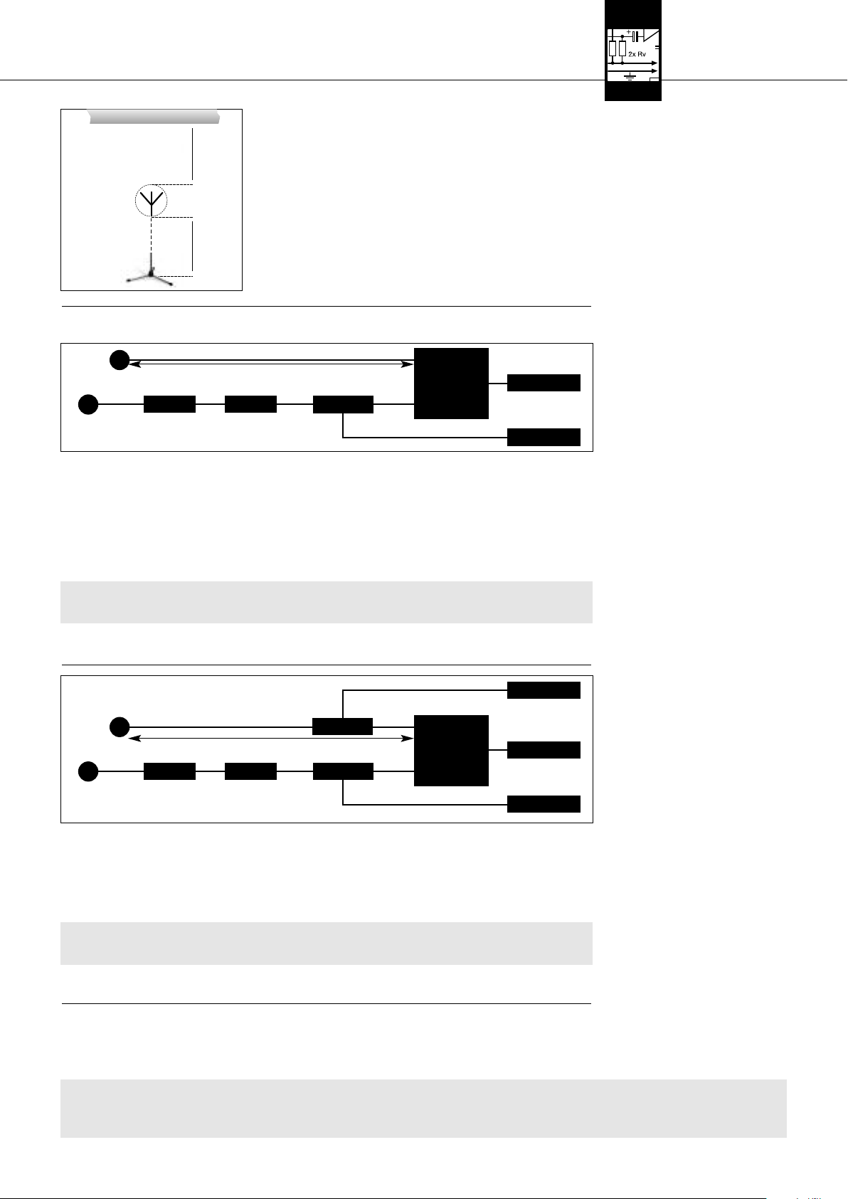
≥ 50 (15) cm
˛
˛
˛
≥ 15cm
˛
3 Messa in esercizio
2. F
ate attenzione che l’antenna abbia una distanza minima di 15 cm dal pavimen-
to, rispettivamente di 50
Fig. 5: Distanza minima da pavimento e soffitto
cm (se il cavo arriva dall’alto: 15 cm) dal soffitto.
Per un impianto mono-canale non avete bisogno di uno splitter d’antenna. Potete collegare le antenne al ricevitore.
Antenna
AA BB BB
Antenna
AA::
RG58: 0 - 13 m / RG213: 5 - 26 m
BB::
RG58: 6 - 46 m / RG213: 12 - 97 m
1. Rilevate la distanza tra il ricevitore e le due antenne SRA 1 da coprire con cavi.
2. Leggete nella tabella 1 a pagina 35, se dovete suddividere l’intera distanza per coprirla con più cavi e avete bisogno di uno o
due amplificatori d’antenna AB 4000. La tabella 1 vi indica la massima lunghezza del cavo ammissibile, a seconda del tipo del
cavo.
3. Inserite in ogni antenna un cavo d’antenna.
4. Collegate le due antenne, seguendo le indicazioni della tabella 1, alle prese d’ingresso d’antenna del ricevitore .
Se avete bisogno di uno o due amplificatori d’antenna AB 4000, dovete inserire nella linea, tra ricevitore ed il primo amplificatore d’antenna, un alimentatore a distanza ASU 4000.
5. Controllate se la tensione di rete indicata sugli alimentatori dell’ASU 4000 e del ricevitore corrisponde alla tensione di
rete del luogo d’impiego. Gestire gli alimentatori con una tensione di alimentazione diversa può causare danni all’apparecchio.
6. Collegate l’alimentatore a distanza e il ricevitore agli alimentatori corrispondenti ed ogni alimentatore ad una presa di rete idonea.
SRA 2 B/W
AA BB BB
SRA 2 B/W
AA::
BB::
RG58: 0 - 13 m / RG213: 5 - 26 m
AABB 44000000
RG58: 0 - 13 m / RG213: 5 - 26 m
AABB 44000000
RG58: 0 - 13 m / RG213: 5 - 26 m
RG58: 6 - 46 m / RG213: 12 - 97 m
AABB 44000000
AABB 44000000 AASSUU 44000000
AASSUU 44000000
AASSUU 44000000
RRiicceevviittoorree
RRiicceevviittoorree
<<-- DDCC//AACC -->>
<<-- DDCC//AACC -->>
<<-- DDCC//AACC -->>
<<-- DDCC//AACC -->>
<<-- DDCC//AACC -->>
33..44 CCoommee ccoolllleeggaarree llee aanntteennnnee
33..44..11 IImm ppiiaannttoo mmoonnoo--ccaannaallee
ccoonn aanntteennnnee ppaassssiivvee
Vedi tabella 1 a pagina 35 e fig. 6.
Fig. 6:
Cablaggio di un impianto monocanale con antenne passive e cavi d'antenna di lunghezza diversa.
Vedi fig. 6.
IImmppoorrttaannttee!!
!
L
33..44..22 IImm ppiiaannttii mmoonnoo--ccaannaallee
ccoonn aanntteennnnee aattttiivvee
Vedi tabella 1 a pagina 35 e fig. 7.
Cablaggio di un impianto mono-
Fig. 7:
canale con antenne attive e cavi d'antenna
di lunghezze diverse.
1. Rilevate la distanza tra il ricevitore e le due antenne attive da coprire con cavi.
2. Leggete nella tabella 1 a pagina 35 se dovete coprire l’intera distanza con più cavi e se avete bisogno di uno o due amplificatori d’antenna AB 4000. La tabella 1 vi indica la massima lunghezza del cavo ammissibile, a seconda del tipo del cavo.
3. Inserite in ogni antenna un cavo d’antenna.
4. Collegate le due antenne, seguendo le indicazioni della tabella 1, ad uno o due amplificatori d’antenna AB 4000, rispettivamente ad un alimentatore a distanza ASU 4000 e alle prese d’ingresso d’antenna del ricevitore .
5. Controllate se la tensione di rete indicata sugli alimentatori dei due ASU 4000 e del ricevitore corrisponde alla tensione di rete del luogo d’impiego. Gestire gli alimentatori con una tensione di rete diversa può causare danni all’apparecchio.
6. Collegate i due alimentatori a distanza nonché il ricevitore agli alimentatori corrispondenti ed ogni alimentatore ad una presa di
rete idonea.
Esempi di cablaggi per impianti pluri-canale sono illustrati nelle figure 10 a 13 a pagina 56.
Quando configurate un impianto pluri-canale, tenete presenti i seguenti punti:
1. Allo splitter d’antenna PS 4000 W potete collegare fino a quattro ricevitori .
• Se gestite sia lo splitter d’antenna che i ricevitori con l’alimentatore rispettivamente in dotazione, dovete assolutamente collegare gli alimentatori dei ricevitori alla rete prima di collegare l’alimentatore dello splitter d’antenna alla
rete. Se collegate prima lo splitter d’antenna alla rete, il sovraccarico causato dai ricevitori potrà danneggiare l’alimentatore dello splitter d’antenna.
Vedi fig. 7.
IImmppoorrttaannttee!!
!
L
33..55 IImmppiiaannttii pplluurrii--ccaannaallee
ccoonn sspplliitttteerr dd’’aanntteennnnaa PPSS 44000000 WW
AAvvvveerrtteennzzaa!!
!
L
AKG PS 4000 W 33
Page 34

3 Messa in esercizio
2. Per impianti più grandi con fino a 50 canali potete collegare insieme un numero corrispondente di splitter d’antenna:
• Collegate le prese LINK del primo splitter d’antenna sempre alle prese ANTENNA IN del prossimo splitter d’antenna e così
via.
• Per alimentare impianti di questo genere raccomandiamo l’alimentatore centrale opzionale PSU 4000 per rispettivamente
tre splitter d’antenna e quattro ricevitori.
3. Ogni ingresso d’antenna dello splitter d’antenna è in grado di alimentare, attraverso i cavi d’antenna, al massimo tre componenti
attivi (p.e. RA 4000 B/W + 2 x AB 4000).
Nei casi qui di seguito indicati avete bisogno di un alimentatore a distanza ASU 4000 per alimentare i componenti attivi
(l’ASU 4000 può alimentare pure tre componenti attivi):
• La distanza da coprire con cavi tra splitter d’antenna e componente attivo è così lunga che la tensione di alimentazione scen-
de al di sotto del valore minimo ammissibile.
• Tra PS 4000 W e componente attivo è disposto un apparecchio (p.e. un Combiner d’antenna*) che interrompe la tensione
di alimentazione c.c. nel cavo d’antenna.
NNoottaa::
33..66 IInntteerrrruuttttoorree CCLLAA
* Il Combiner d’antenna ZAPD 21 della ditta Mini Circuit fa passare la tensione di alimentazione, altri prodotti non garantisco-
no questo passaggio.
• Avete collegato, per mezzo di un Combiner d’antenna, due linee d’antenna ad un ingresso d’antenna. Se gestite tre o più
componenti attivi in una linea d’antenna, inserite un alimentatore a distanza ASU 4000 tra il Combiner d’antenna ed il primo
di questi componenti attivi. Se, nella somma delle due linee d’antenna, gestite più di tre componenti attivi, avete bisogno per
ogni linea d’antenna di un alimentatore a distanza ASU 4000. L’alimentatore a distanza è necessario per evitare il sovraccarico dell’alimentatore dello splitter d’antenna.
Il livello del segnale RF di ogni ingresso d’antenna dello (degli) splitter d’antenna dipende dalla gamma delle frequenze, dal tipo d’antenna, dal tipo di cavo e dalla lunghezza del cavo.
Per garantire un ottimale livello di segnale RF all’ingresso d’antenna, dovete regolare l’interruttore CLA di ogni amplificatore d’antenna nonché dello (degli) splitter d’antenna secondo le indicazioni riportate nella tabella 1.
1. Togliete la copertura dell’interruttore CLA.
2. Regolate i tre interruttori DIP a seconda della gamma di frequenze, del tipo d’antenna, del tipo di cavo e della lunghezza del cavo.
3. Rimontate la copertura.
34 AKG PS 4000 W
Page 35

A
CLA
A B
CLA
A
3 Messa in esercizio
CLA
CLA
CLA
B B
CLA
CLA
ON
1 2 3
14 dB
12 dB
10 dB
8 dB
6 dB
4 dB
2 dB
0 dB
RG58 RG213 CLA RG58 RG213 CLA RG58 RG213 CLA
53 - 57 111 - 121 0 38 - 43 79 - 89 0 41 - 46 87 - 97 0
48 - 53 100 - 111 2 33 - 38 68 - 79 2 36 - 41 76 - 87 2
43 - 48 89 - 100 4 28 - 33 58 - 68 4 31 - 36 66 - 76 4
38 - 43 79 - 89 6 23 - 28 47 - 58 6 26 - 31 55 - 66 6
GAMMA I + IIGAMMA III + IVGAMMA V + VI
33 - 38 68 - 79 8 18 - 23 37 - 47 8 21 - 26 45 - 55 8
28 - 33 58 - 68 10 13 - 18 26 - 37 10 16 - 21 34 - 45 10
23 - 28 47 - 58 12 8 - 13 16 - 26 12 11 - 16 24 - 34 12
18 - 23 37 - 47 14 3 - 8 5 - 16 14 6 - 11 13 - 24 14
RG58 RG213 CLA RG58 RG213 CLA RG58 RG213 CLA RG58 RG213 CLA
50 - 55 105 - 115 0 36 - 40 75 - 85 0 7 - 12 15 - 25 0 39 - 44 83 - 93 0
45 - 50 95 - 105 2 31 - 36 65 - 75 2 2 - 7 5 - 15 2 35 - 39 73 - 83 2
40 - 45 85 - 95 4 26 - 31 55 - 65 4 0 - 2 4 30 - 35 63 - 73 4
36 - 40 75 - 85 6 21 - 26 45 - 55 6625 - 30 53 - 63 6
31 - 36 65 - 75 8 17 - 21 35 - 45 8820 - 25 43 - 53 8
26 - 31 55 - 65 10 12 - 17 25 - 35 10 10 15 - 20 33 - 43 10
21 - 26 45 - 55 12 7 - 12 15 - 25 12 12 11 - 15 23 - 33 12
17 - 21 35 - 45 14 2 - 7 5 - 15 14 14 6 - 11 13 - 23 14
RG58 RG213 CLA RG58 RG213 CLA RG58 RG213 CLA RG58 RG213 CLA
47 - 51 100 - 110 0 33 - 38 71 - 81 0 7 - 11 14 - 24 0 37 - 41 79 - 88 0
42 - 47 90 - 100 2 29 - 33 62 - 71 2 2 - 7 5 - 14 2 32 - 37 69 - 79 2
38 - 42 81 - 90 4 24 - 29 52 - 62 4 0 - 2 4 28 - 32 60 - 69 4
34 - 38 71 - 81 6 20 - 24 43 - 52 6623 - 28 50 - 60 6
29 - 34 62 - 71 8 16 - 20 33 - 43 8819 - 23 40 - 50 8
24 - 29 52 - 62 10 11 - 16 24 - 33 10 10 14 - 19 31 - 40 10
20 - 24 43 - 52 12 7 - 11 14 - 24 12 12 10 - 14 21 - 31 12
16 - 20 33 - 43 14 2 - 7 5 - 14 14 14 6 - 10 12 - 21 14
RG58 RG213 CLA RG58 RG213 CLA RG58 RG213 CLA
56 - 60 132 - 140 0 44 - 46 102 - 108 0 49 - 50 110 - 118 0
51 - 56 120 - 132 2 40 - 44 93 - 102 2 47 - 49 100 - 110 2
46 - 51 108 - 120 4 36 - 40 84 - 93 4 42 - 47 90 - 100 4
41 - 46 97 - 108 6 32 - 36 75 - 84 6 36 - 42 81 - 90 6
GAMMA VIIGAMMA VIII
36 - 41 83 - 97 8 28 - 32 66 - 75 8 31 - 36 70 - 81 8
31 - 36 71 - 83 10 25 - 28 57 - 66 10 27 - 31 60 - 70 10
26 - 31 60 - 71 12 21 - 25 48 - 57 12 23 - 27 50 - 60 12
23 - 26 52 - 60 14 18 - 21 42 - 48 14 19 - 23 44 - 50 14
RG58 RG213 CLA RG58 RG213 CLA RG58 RG213 CLA
53 - 56 122 - 131 0 40 - 44 94 - 101 0 43 - 46 102 - 107 0
48 - 53 110 - 122 2 35 - 40 82 - 94 2 38 - 43 88 - 102 2
43 - 48 99 - 110 4 30 - 35 70 - 82 4 33 - 38 76 - 88 4
38 - 43 88 - 99 6 25 - 30 58 - 70 6 28 - 33 64 - 76 6
33 - 38 79 - 88 8 22 - 25 46 - 58 8 23 - 28 52 - 64 8
28 - 33 63 - 74 10 16 - 22 34 - 46 10 18 - 23 40 - 52 10
23 - 28 50 - 63 12 11 - 16 22 - 34 12 13 - 18 28 - 40 12
20 - 23 43 - 50 14 7 - 11 15 - 22 14 10 - 13 20 - 28 14
SRA 2 B/W RA 4000 B/W
(m) (m) (dB) (m) (m) (dB) (m) (m) (dB)
SRA 2 B/W RA 4000 B/W
(m) (m) (dB) (m) (m) (dB) (m) (m) (dB) (m) (m) (dB)
SRA 2 B/W RA 4000 B/W
(m) (m) (dB) (m) (m) (dB) (m) (m) (dB) (m) (m) (dB)
SRA 2 B/W RA 4000 B/W
(m) (m) (dB) (m) (m) (dB) (m) (m) (dB)
SRA 2 B/W RA 4000 B/W
(m) (m) (dB) (m) (m) (dB) (m) (m) (dB)
A
A
A
A
A
Tabella 1: Posizioni degli interruttori DIP CLA a seconda della gamma di frequenze, del tipo d’antenna, del tipo di cavo e della lunghezza del cavo
B
B
B
B
B
AKG PS 4000 W 35
Page 36

4 Indicazioni per l’esercizio
44..11 IInnddiiccaazziioonnii ggeenneerraallii
Importante!
44..22 IImm ppiiaannttii ccoonn aalliimmeennttaattoorrii
44..22..11 AAttttiivvaazziioonnee
44..22..22 DDiissaattttiivvaazziioonnee
44..33 IImm ppiiaannttii ccoonn aalliimmeennttaattoorree cceenn--
ttrraallee ooppzziioonnaallee PPSSUU 44000000
44..33..11 AAttttiivvaazziioonnee
44..33..22 DDiissaattttiivvaazziioonnee
!
L
ddeecceennttrraallii
1. Tenete presente che ogni canale di trasmissione (trasmettitore + ricevitore) deve essere regolato su una propria frequenza.
2. Non gestite mai più di un canale di trasmissione contemporaneamente sullo stesso posto e sulla stessa frequenza. Per ragioni
fisiche, si verificherebbero forti rumori disturbanti.
• Quando attivate e disattivate l’impianto, dovete assolutamente rispettare la successione dei passi indicata nei capitoli 4.2 e 4.3 per evitare danni all’alimentatore dello splitter d’antenna causati da sovraccarico.
1. Attivate i trasmettitori.
2. Attivate tutti i ricevitori collegati allo splitter d’antenna.
3. Attivate lo splitter d’antenna premendo il tasto ON/OFF.
I LED OK blu sullo splitter d’antenna nonché i LED di controllo verdi dei componenti attivi collegati si accendono.
1. Disattivate tutti i ricevitori collegati allo splitter d’antenna.
2. Disattivate i trasmettitori.
3. Disattivate lo splitter d’antenna premendo il tasto ON/OFF.
I LED OK blu sullo splitter d’antenna nonché i LED di controllo verdi dei componenti attivi collegati si spengono.
1. Attivate l’alimentatore centrale PSU 4000.
2. Attivate i ricevitori.
3. Attivate lo splitter d’antenna premendo il tasto ON/OFF.
I LED OK blu sullo splitter d’antenna nonché i LED di controllo verdi dei componenti attivi collegati si accendono.
4. Attivate tutti i ricevitori collegati allo splitter d’antenna.
1. Disattivate tutti i ricevitori collegati allo splitter d’antenna.
2. Disattivate i ricevitori.
3. Disattivate lo splitter d’antenna premendo il tasto ON/OFF.
I LED OK blu sullo splitter d’antenna nonché i LED di controllo verdi dei componenti attivi collegati si spengono.
4. Disattivate l’alimentatore centrale PSU 4000.
5 Pulizia
• Per pulire le superfici dello splitter d'antenna usate un panno morbido inumidito di acqua.
6 Errori e rimedi
Errore Possibile causa Rimedio
Non c’è suono.
Nessuna ricezione o ricezione disturbata
su singoli canali.
1. Gli alimentatori/PSU 4000 non sono collegati ad una
presa di rete.
2. I cavi c.c. non sono collegati o sono difettosi.
3. Le antenne non sono collegate.
4. L’alimentatore (gli alimentatori)/PSU 4000 è (sono)
difettoso(i).
1. Il trasmettitore e/o il ricevitore non è (sono) inserito(i).
2. Le pile del trasmettitore sono esauste.
3. L’alimentatore di rete del ricevitore rispettivamente il
cavo di collegamento dal PSU 4000 al ricevitore:
a) ha un cattivo contatto o
b) è difettoso.
4. Trasmettitore e ricevitore del rispettivo canale non
sono sintonizzati sulla stessa frequenza.
5. Il trasmettitore o il ricevitore è difettoso.
1. Collegare gli alimentatori/PSU 4000 ad una presa di
rete.
2. Collegare i cavi c.c. o sostituirli.
3. Collegare le antenne.
4. Rivolgetevi al vostro punto service AKG.
1. Inserire il trasmettitore e/o il ricevitore.
2. Sostituire le pile del trasmettitore.
3. a) Controllare la sede del connettore dell’alimentatore
di rete rispettivamente del cavo di collegamento o
b) sostituire l’alimentatore di rete o il cavo di collega-
mento.
4. Sintonizzare il trasmettitore e il ricevitore sulla stessa
frequenza. Leggete in merito le istruzioni per l’uso del
trasmettitore e del ricevitore.
5. Rivolgetevi al vostro rivenditore AKG.
Il LED verde di un componente attivo
d’antenna non si accende.
Uno dei LED ERROR dello splitter
d’antenna si accende.
1. Il cavo d’antenna non è collegato o ha un contatto
cattivo.
2. Il cavo d’antenna è difettoso.
3. Il componente attivo è difettoso.
1. La tensione d’alimentazione per i componenti d’antenna attivi è cortocircuitata.
2. La tensione d’alimentazione dei componenti attivi
d’antenna è troppo bassa, causa i cavi troppo lunghi.
1. Collegare il cavo d’antenna o verificare se il connettore è inserito bene.
2. Sostituire il cavo d’antenna.
3. Rivolgetevi al vostro punto service AKG.
1. Controllare tutti i cavi collegati e tutti i componenti
attivi d’antenna. Sostituire cavi e/o componenti difettosi.
2. Controllare, in base alla tabella 1, la lunghezza dei
cavi collegati, usare cavi più corti o spezzare i cavi e
inserire l’ASU 4000 (vedi anche i diagrammi di
cablaggio).
36 AKG PS 4000 W
Page 37

7 Dati tecnici
Splitter d’antenna PS 4000 W
Tipo: 2 x 1 su 4 ricevitori + 2 x 1 PS (collegabile in cascata)
Gamma delle frequenze portanti: 500 - 865 MHz
Attenuazione: 0, 2, 4, 6, 8, 10, 12, 14 dB, regolabile
Ingressi RF: 2 prese BNC, 50 Ohm
Uscite RF: 10 prese BNC, 50 Ohm
Tensione d’alimentazione: 12 V c.c.
Dimensioni: 200 x 190 x 44 mm
Peso: circa 970 g
Amplificatore d’antenna AB 4000
Gamma delle frequenze portanti: 500 - 865 MHz
Amplificazione: circa 17 - 3,5 dB, regolabile
Ingresso RF: 1 presa BNC, 50 Ohm
Uscita RF: 1 presa BNC, 50 Ohm
Tensione d’alimentazione: 8 V c.c., fornita attraverso cavo d’antenna da PS 4000 W o ASU 4000
Dimensioni: 110 x 35 mm
Peso: circa 150 g
Antenna onnidirezionale con booster RA 4000 B/W
Gamma delle frequenze portanti: 500 - 865 MHz
Guadagno e amplificazione: 17 dB
Ingresso RF: 1 presa BNC, 50 Ohm
Uscita RF: 1 presa BNC, 50 Ohm
Tensione d’alimentazione: 8 V c.c., fornita attraverso cavo d’antenna da PS 4000 W o ASU 4000
Dimensioni: 235 x 38,5 mm
Peso: 65 g
Antenna direzionale passiva SRA 2 B/W
Gamma delle frequenze portanti: 500 - 865 MHz
Guadagno e amplificazione: 21,5 dB
Angolo d’apertura: 70°
Dimensioni: 230 x 240 x 26 mm
Peso: circa 250 g
Alimentatore a distanza ASU 4000
Gamma delle frequenze portanti: 500 - 865 MHz
Ingresso RF: 1 presa BNC, 50 Ohm
Uscita RF: 1 presa BNC, 50 Ohm
Tensione d’alimentazione: 12 V c.c.
Dimensioni: 78 x 50 x 50 mm
Peso: circa 150 g
Questo prodotto corrisponde alle norme elencate nella dichiarazione di conformità, che è disponibile al sito http://www.akg.com oppure all'indirizzo email sales@akg.com.
AKG PS 4000 W 37
Page 38

Indice
1 Seguridad y medio ambiente . . . . . . . . . . . . . . . . . . . . . . . . . . . . . . . . . . . . . . . . . . . . . . . . . . . . . . . . . . . . 38
1.1 Seguridad . . . . . . . . . . . . . . . . . . . . . . . . . . . . . . . . . . . . . . . . . . . . . . . . . . . . . . . . . . . . . . . . . . . . . . . 38
1.2 Medio ambiente . . . . . . . . . . . . . . . . . . . . . . . . . . . . . . . . . . . . . . . . . . . . . . . . . . . . . . . . . . . . . . . . . . . 39
2 Descripción . . . . . . . . . . . . . . . . . . . . . . . . . . . . . . . . . . . . . . . . . . . . . . . . . . . . . . . . . . . . . . . . . . . . . . . . . . . 39
2.1 Introducción. . . . . . . . . . . . . . . . . . . . . . . . . . . . . . . . . . . . . . . . . . . . . . . . . . . . . . . . . . . . . . . . . . . . . . 39
2.2 Volumen de suministros . . . . . . . . . . . . . . . . . . . . . . . . . . . . . . . . . . . . . . . . . . . . . . . . . . . . . . . . . . . . . 39
2.3 Accesorios opcionales . . . . . . . . . . . . . . . . . . . . . . . . . . . . . . . . . . . . . . . . . . . . . . . . . . . . . . . . . . . . . . 39
2.4 Descripción . . . . . . . . . . . . . . . . . . . . . . . . . . . . . . . . . . . . . . . . . . . . . . . . . . . . . . . . . . . . . . . . . . . . . . 39
2.4.1 Frente . . . . . . . . . . . . . . . . . . . . . . . . . . . . . . . . . . . . . . . . . . . . . . . . . . . . . . . . . . . . . . . . . . . . . 39
2.4.2 Parte posterior . . . . . . . . . . . . . . . . . . . . . . . . . . . . . . . . . . . . . . . . . . . . . . . . . . . . . . . . . . . . . . . 40
2.5 Unidad de alimentación central PSU 4000 (opcional) . . . . . . . . . . . . . . . . . . . . . . . . . . . . . . . . . . . . . . . . 40
2.6 Antenas de recepción (opcional) . . . . . . . . . . . . . . . . . . . . . . . . . . . . . . . . . . . . . . . . . . . . . . . . . . . . . . . 40
2.6.1 SRA 2 B/W . . . . . . . . . . . . . . . . . . . . . . . . . . . . . . . . . . . . . . . . . . . . . . . . . . . . . . . . . . . . . . . . . . 40
2.6.2 RA 4000 B/W . . . . . . . . . . . . . . . . . . . . . . . . . . . . . . . . . . . . . . . . . . . . . . . . . . . . . . . . . . . . . . . . 40
3 Puesta en funcionamiento . . . . . . . . . . . . . . . . . . . . . . . . . . . . . . . . . . . . . . . . . . . . . . . . . . . . . . . . . . . . . . 41
3.1 Montaje de un divisor de antenas en el bastidor . . . . . . . . . . . . . . . . . . . . . . . . . . . . . . . . . . . . . . . . . . . 41
3.2 Montaje de dos divisores de antenas en el bastidor . . . . . . . . . . . . . . . . . . . . . . . . . . . . . . . . . . . . . . . . . 41
3.3 Instalación de antenas . . . . . . . . . . . . . . . . . . . . . . . . . . . . . . . . . . . . . . . . . . . . . . . . . . . . . . . . . . . . . . 41
3.3.1 Lugar de instalación . . . . . . . . . . . . . . . . . . . . . . . . . . . . . . . . . . . . . . . . . . . . . . . . . . . . . . . . . . . 41
3.3.2 Instalación en trípodes de suelo. . . . . . . . . . . . . . . . . . . . . . . . . . . . . . . . . . . . . . . . . . . . . . . . . . . 41
3.3.3 Instalación en muros/techos . . . . . . . . . . . . . . . . . . . . . . . . . . . . . . . . . . . . . . . . . . . . . . . . . . . . . 41
3.4 Conexión de antenas . . . . . . . . . . . . . . . . . . . . . . . . . . . . . . . . . . . . . . . . . . . . . . . . . . . . . . . . . . . . . . . 42
3.4.1 Sistema monocanal con antenas pasivas SRA 1 . . . . . . . . . . . . . . . . . . . . . . . . . . . . . . . . . . . . . . . 42
3.4.2 Sistema monocanal con antenas activas . . . . . . . . . . . . . . . . . . . . . . . . . . . . . . . . . . . . . . . . . . . . 42
3.5 Sistemas multicanal con divisor de antenas PS 4000 W. . . . . . . . . . . . . . . . . . . . . . . . . . . . . . . . . . . . . . 42
3.6 Conmutador CLA . . . . . . . . . . . . . . . . . . . . . . . . . . . . . . . . . . . . . . . . . . . . . . . . . . . . . . . . . . . . . . . . . . 43
4 Instrucciones de funcionamiento . . . . . . . . . . . . . . . . . . . . . . . . . . . . . . . . . . . . . . . . . . . . . . . . . . . . . . . . . 45
4.1 Instrucciones generales . . . . . . . . . . . . . . . . . . . . . . . . . . . . . . . . . . . . . . . . . . . . . . . . . . . . . . . . . . . . . 45
4.2 Sistemas con alimentación descentralizada . . . . . . . . . . . . . . . . . . . . . . . . . . . . . . . . . . . . . . . . . . . . . . . 45
4.2.1 Encender . . . . . . . . . . . . . . . . . . . . . . . . . . . . . . . . . . . . . . . . . . . . . . . . . . . . . . . . . . . . . . . . . . . 45
4.2.2 Apagar . . . . . . . . . . . . . . . . . . . . . . . . . . . . . . . . . . . . . . . . . . . . . . . . . . . . . . . . . . . . . . . . . . . . . 45
4.3 Sistemas con alimentación central PSU 4000 opcional. . . . . . . . . . . . . . . . . . . . . . . . . . . . . . . . . . . . . . . 45
4.3.1 Encender . . . . . . . . . . . . . . . . . . . . . . . . . . . . . . . . . . . . . . . . . . . . . . . . . . . . . . . . . . . . . . . . . . . 45
4.3.2 Apagar . . . . . . . . . . . . . . . . . . . . . . . . . . . . . . . . . . . . . . . . . . . . . . . . . . . . . . . . . . . . . . . . . . . . . 45
!
L
11..11 SSeegguurr iiddaadd
5 Limpieza . . . . . . . . . . . . . . . . . . . . . . . . . . . . . . . . . . . . . . . . . . . . . . . . . . . . . . . . . . . . . . . . . . . . . . . . . . . . 45
6 Solución de errores . . . . . . . . . . . . . . . . . . . . . . . . . . . . . . . . . . . . . . . . . . . . . . . . . . . . . . . . . . . . . . . . . . . 45
7 Datos técnicos . . . . . . . . . . . . . . . . . . . . . . . . . . . . . . . . . . . . . . . . . . . . . . . . . . . . . . . . . . . . . . . . . . . . . . . 46
Fig. 8 a 13 . . . . . . . . . . . . . . . . . . . . . . . . . . . . . . . . . . . . . . . . . . . . . . . . . . . . . . . . . . . . . . . . . . . . . . . . . . . . . 56
1 Seguridad y medio ambiente
1. No verter líquidos sobre el equipo y no dejar caer objetos a través de las ranuras de ventilación.
2. Utilice el aparato sólo en lugares secos.
3. El personal técnico calificado es el único autorizado para abrir, atender y reparar el aparato. En el interior de la caja no se encuentra ninguna pieza que pueda ser atendida, reparada o cambiada por un profano.
4. Antes de utilizar el aparato, verifique que la tensión de servicio corresponda a la tensión de red en el lugar de utilización.
5. Utilice el aparato solamente con el alimentador de red de tensión alterna con tensión de salida de 12 V DC. ¡Otros tipos de
corriente pueden dañar seriamente el aparato!
6. Ponga inmediatamente fuera de servicio el equipo si llegara a penetrar algún objeto sólido o un líquido al interior del aparato.
En ese caso tiene que desenchufar inmediatamente el alimentador de red y el aparato debe ser examinado por nuestro servicio de atención al cliente.
7. Si el aparato no se va a utilizar durante largo tiempo, debe desenchufar el alimentador de red. Por favor, recuerde que si el alimentador de red permanece enchufado, el aparato no se desconecta completamente de la red cuando se apaga.
8. No colocar el aparato cerca de fuentes de calor, como p.ej radiadores, tubos de calefacción, amplificadores, etc. y no exponerlo directamente al sol, a polvo o humedad intensos, a la lluvia, a vibraciones o a golpes.
9. Para evitar perturbaciones o interferencias, todas las líneas de audio, y sobre todo las de las entradas de micrófono, deben tenderse separadas de las líneas de alta intensidad y de alimentación. Si el tendido se hace en una caja de entrada de cables o en
canales para cables, las líneas de audio deben colocarse en un canal separado.
10. Para limpiar el aparato, utilice únicamente un paño húmedo, pero no mojado. ¡Antes de proceder a la limpieza desenchufe el
alimentador de red! No debe utilizar nunca materiales de limpieza corrosivos o abrasivos ni aquellos que contengan alcohol o
disolventes, puesto que pueden dañar la laca o las piezas de material sintético.
11. El aparato debe ser utilizado sólo para los fines descriptos en estas instrucciones de uso. AKG no se responsabiliza por daños
debidos a un uso inadecuado o indebido.
11..22 MM eeddiioo aammbbiieennttee
38 AKG PS 4000 W
1. El alimentador de red sigue recibiendo un poco de corriente aun estando apagado el aparato. Para ahorrar energía, desenchufe el alimentador de red si no va a utilizar el aparato durante largo tiempo.
2. Para desguazar el aparato hay que sacar las pilas o los acumuladores, separar la caja, la electrónica y el cable y proceder a la
eliminación de todos los componentes atendiendo a las correspondientes disposiciones de eliminación de residuos vigentes.
3. El embalaje es reciclable. Elimine el embalaje en un sistema de recogida previsto para ello.
Page 39

2 Descripción
Muchas gracias por
de Empleo antes de usar el aparato. Guarde las instrucciones de empleo en un lugar seguro de modo que pueda consultarlas si
se le presenta alguna duda. ¡Que se divierta y que tenga mucho éxito con su nuevo equipo!
Verifique que el embalaje contenga todos los elementos arriba indicados. Si falta algo, por favor contacte con su distribuidor AKG.
haberse decidido por un producto de la empresa AKG. Tómese, por favor, unos momentos para leer el Modo
1 divisor de antenas PS 4000 W 1 juego de montaje de 19"
• Adaptador de red de 12 V DC
• Antena direccional activa SRA 2 B/W
• Antena omnidireccional activa
RA 4000 B/W
• Cables de antena MK PS
• Unidad de alimentación central PSU 4000
• Unidad de alimentación remota ASU 4000
22..11 IInnttrroodduucccciióónn
22..22 VVoolluummeenn ddee ssuumm iinniissttrrooss
22..33 AAcccceessoorriiooss ooppcciioonnaalleess
• Amplificador de antena AB 4000
El divisor de antenas PS 4000 W es un distribuidor de antenas para la configuración de un sistema multicanal UHF con hasta cuatro receptores por cada divisor de antenas (el número exacto de canales que pueden hacerse funcionar simultáneamente depende
del plan de frecuencias del país en que se utilice).
El PS 4000 W posee dos entradas hembra de antena, a las que puede conectarse las antenas de recepción activas SRA 2 B/W ó
RA 4000 B/W con Booster (amplificador de antena) incorporado. Las entradas de antena ponen a disposición una tensión de alimentación de 12 V DC para un máximo de tres componentes de antena activos, p.e. una antena activa y dos amplificadores de antena AB 4000. En la parte posterior del divisor de antenas hay además 2 x 4 salidas hembra de antena para hasta 4 receptores en
diversidad así como también dos salidas hembra de antena adicionales para la transmisión de la señal de antena a varios divisores
de antenas PS 4000 W adicionales.
El PS 4000 W posee una robusta caja metálica de 44,45 mm de altura y de un ancho de la mitad de 19", para el montaje de dos
divisores de antenas, uno al lado del otro, en un nivel del bastidor.
La alimentación de energía eléctrica del PS 4000 W se realiza a través de un adaptador de red opcional. Para sistemas de más de
4 canales, recomendamos una unidad de alimentación central PSU 4000 opcional por cada tres divisores de antenas.
Tanto el amplificador de antena como el divisor de antenas son aparatos de banda ancha para toda la gama de frecuencias UHF.
En el frente del divisor de antenas están los siguientes elementos de mando e indicadores:
22..44 DDeessccrriippcciióónn
22..44..11 FFrreennttee
Fig. 1: Frente del PS 4000 W
ON/OFF: Tecla para encender/apagar. Para encender el aparato, pulse la tecla. Para apagarlo, vuelva a pulsar la tecla.
ANTENNA A, ANTENNA B: El LED OK azul emite luz cuando en la entrada hembra de antena ANTENNA A IN/ANTENNA B IN se dis-
pone de la correcta tensión de alimentación para componentes activos.
Si en una entrada de antena se produce un cortocircuito o fallo (caída por debajo de los 2 V) de la tensión de alimentación, el
respectivo LED OK deja de emitir luz y el LED ERROR rojo empieza a emitir luz.
• Los LEDs OK NO indican el estado de funcionamiento del correspondiente amplificador de antena y, por lo tanto, no dejan de
emitir luz cuando se desconecta un cable de antena.
CLA: Debajo de la tapa con el logo AKG hay un conmutador DIP de tres posiciones para el ajuste de las entradas de antenas (ANTEN-
NA A IN, ANTENNA B IN) a las diferentes longitudes de cable de antena.
NNoottaa::
Ver Tabla 1 de la página 44.
AKG PS 4000 W 39
Page 40

22..44..22 PPaarrttee ppoosstteerriioorr
Fig. 2: Parte posterior del PS 4000 W
2 Descripción
En la parte posterior del PS 4000 W están las siguientes entradas y salidas:
DC IN 12 V/2 A: Entrada hembra para un adaptador de red opcional o la unidad de alimentación central PSU 4000 opcional.
ANTENNA A IN, ANTENNA B IN: Entradas hembra BNC para las antenas de recepción remotas SRA 2 B/W ó RA 4000 B/W. Si uti-
lize receptores en diversidad, necesitará dos antenas de recepción (no incluidas en el volumen de suministros). Las entradas
hembra de antena ponen a disposición una tensión de alimentación de 12 V DC para antenas activas.
ANTENNA A OUT TO SR: En las cuatro salidas hembra BNC 1A a 4A está disponible la señal de antena para la sección receptora
A de hasta cuatro receptores en diversidad. Todas las salidas no utilizadas se terminan eléctricamente en forma automática.
ANTENNA B OUT TO SR: En las cuatro salidas hembra BNC 1B a 4B está disponible la señal de antena para la sección receptora
B de hasta cuatro receptores en diversidad. Todas las salidas no utilizadas se terminan eléctricamente en forma automática.
Además de la señal de antena, las salidas hembra 1A a 4A y 1B a 4B suministran una tensión de alimentación de 12 V DC para
el receptor conectado.
¡Importante!
Ver también los
22..55 UUnniiddaadd ddee aalliimm eennttaacciióónn cceennttrraall
diagramas de cableado
Fig. 10 a Fig. 13.
PPSSUU 44000000 ((ooppcciioonnaall))
22..66 AAnntteennaass ddee rreecceeppcciióónn
22..66..11 SSRRAA 22 BB//WW
22..66..22 RRAA 44000000 BB//WW
!
L
((ooppcciioonnaalleess))
• La energía eléctrica en las salidas hembra 1A a 4B sólo es suficiente para alimentar los receptores conectados si el
divisor de antenas está conectado a una unidad de alimentación central PSU 4000 opcional.
• Si utiliza el divisor de antenas PS 4000 W con un adaptador de red por separado (opcional), debe utilizar también todos
los receptores con un adaptador de red por separado (opcional). Si conecta los receptores al divisor de antenas sin
un adaptador de red, el adaptador de red del divisor de antenas puede ser dañado por sobrecarga.
LINK A TO PS, LINK B TO PS: En estas salidas hembra BNC está disponible la señal de alta frecuencia (RF) de ambas antenas A y
B. Los conectores hembra LINK se pueden conectar a las entradas hembra de antena de otro divisor de antenas PS 4000 W y
de este modo conectar en cascada más divisores de antenas.
Tenga en cuenta que para cada tres divisores de antenas PS 4000 W se requiere una unidad de alimentación central PSU 4000
opcional.
La unidad de alimentación central PSU 4000 suministra una tensión secundaria de 12 V DC, 2 A para tres divisores de antenas
PS 4000 W y los receptores conectados a ellos (máx. 12). Para mayor información, lea las instrucciones de uso de la PSU 4000.
Para el sistema de antenas PS 4000 W se dispone de antenas direccionales pasivas y activas, y antenas omnidireccionales pasivas
y activas. Todas las antenas son antenas de banda ancha para todo el rango de frecuencias UHF.
Las antenas activas son alimentadas eléctricamente por el divisor de antenas PS 4000 W a través del cable de antena. En sistemas
complejos con cables de antena largos, recomendamos utilizar las antenas activas con una unidad de alimentación central PSU 4000
a través de una unidad de alimentación remota ASU 4000 para cada antena.
La SRA 2 B/W es una antena direccional activa con robusta caja resistente al agua, para utilización en edificios o al aire libre y especialmente para instalación a mayor distancia del radio de acción. Un potente amplificador de antena integrado permite instalarla a
hasta 100 metros de distancia del receptor. Utilizando cables de antena RG213 y 2 amplificadores de antena AB 4000 en serie, es
posible colocar la SRA 2 B/W incluso hasta a 200 metros de distancia del receptor.
Esta antena posee una salida hembra BNC, un LED de control del funcionamiento y un adaptador de soporte integrado.
La RA 4000 B/W es una antena activa omnidireccional con robusta caja resistente al agua, para utilización en edificios y al aire libre
y especialmente para instalación en las cercanías del radio de acción. Un potente amplificador de antena integrado permite instalarla a hasta 100 metros de distancia del receptor. Utilizando cables de antena RG213 y 2 amplificadores de antena AB 4000 en
serie, es posible colocar la RA 4000 B/W incluso hasta a 200 metros de distancia del receptor.
Esta antena posee una salida hembra BNC, un LED de control del funcionamiento y un adaptador de soporte integrado.
40 AKG PS 4000 W
Page 41

3 Puesta en funcionamiento
1. Destornille las cuatro patas de goma (1) del lado inferior del divisor de antenas.
2. Destornille los dos tornillos de fijación (2) de cada una de las dos paredes laterales.
3. Atornille con los tornillos de fijación (2) la escuadra de montaje corta (3) a una de las paredes laterales y la escuadra de montaje larga (4) del juego de montaje suministrado a la otra pared lateral.
4. Fije el divisor de antenas en el rack.
1. Destornille las cuatro patas de goma (1) del lado inferior de los divisores de antenas y saque los tornillos (5) de las patas de
goma (1).
2. Destornille los dos tornillos de fijación (2) de la pared lateral derecha de uno de los divisores de antenas y de la pared lateral
izquierda del otro divisor de antenas.
3. Saque las tapas de plástico (3) de las paredes laterales de las que no destornilló los tornillos de fijación (2).
4. Pase una pieza de unión (4) a través de cada una de las ranuras libres de la pared lateral del primer divisor de antenas, de modo
tal que el agujero de fijación de cada pieza de unión quede alineado con el correspondiente agujero roscado del lado inferior del
divisor de antenas.
5. Fije ambas piezas de unión (4) al primer divisor de antenas utilizando dos de los tornillos (5) que sacó de las patas de goma.
6. Una ambos divisores de antenas pasando las piezas de unión (4) del primer divisor de antenas a través de las ranuras libres de
la pared lateral del segundo divisor de antenas de modo tal que el agujero de fijación de ambas piezas de unión (4) queden alineados con el correspondiente agujero roscado del lado inferior del segundo divisor de antenas.
7. Fije las piezas de unión (4) al segundo divisor de antenas utilizando dos de los tornillos (5) que sacó de las patas de goma (1).
8. Atornille una escuadra de montaje corta (6) a la pared lateral exterior de cada uno de los divisores de antenas utilizando para
cada escuadra dos de los tornillos (2) que sacó de las paredes laterales.
9. Fije los divisores de antenas en el rack.
• Guarde los restantes tornillos (5) para utilizarlos en el futuro.
Las siguientes instrucciones para la instalación de antenas son válidas para todos los sistemas monocanal y multicanal independientemente del número de canales.
Reflexiones de la señal emisora en piezas metálicas, paredes, techos, etc., o el eclipsado por el cuerpo humano pueden debilitar o
incluso extinguir la señal emisora directa. Emplace las antenas como sigue:
1. Posicionar las antenas siempre en la cercanía del radio de acción (escenario), manteniendo una distancia mínima de 5 m entre
el transmisor y las antenas y de 20 cm entre las dos antenas.
2. El requisito para una recepción óptima es el contacto visual entre el transmisor y la antena.
3. Posicionar las antenas a una distancia de más de 1,5 m de objetos metálicos grandes, alambre (especialmente malla de alambre) o chapa metálica, muros, tinglados, techos, etc.
4. No colocar las antenas en nichos murales.
5. Emplazar las antenas a por lo menos 1,5 m de aparatos emisores de RF, tales como estantes luminosos, tubos fluorescentes,
aparatos de efectos digitales y PCs.
6. Si instala dos antenas una al lado de la otra, (p.ej. para la recepción en diversidad), verifique que estén a por lo menos 20 cm
de distancia.
33..11 MMoonnttaajjee ddee uunn ddiivviissoorr ddee aanntteennaass
eenn uunn rraacckk
Ver Fig. 8.
33..22 MMoonnttaajjee ddee ddooss ddiivviissoorreess ddee
aanntteennaass eenn uunn rraacckk
Ver Fig. 9.
NNoottaa::
33..33 IInnssttaallaacciióónn ddee aanntteennaass
33..33..11 EEmm ppllaazzaammiieennttoo
≥ 70c m
˛
Si instala las antenas en trípodes de suelo, tenga en cuenta las siguientes instruc-
˛
ciones:
33..33..22 IInnssttaallaacciióónn
eenn ttrrííppooddeess ddee ssuueelloo
1. Fije la antena en el saliente del trípode jirafa utilizando el adaptador de soporte
˛
SA 63 suministrado o el adaptador de soporte integrado.
2. Extienda el saliente completamente hacia un lado, para que la antena esté a una
distancia de por lo menos 70 cm del trípode.
3. Alargue el trípode hasta que la saliente esté a por lo menos 1,8 m del suelo.
≥ 180cm
˛
4. Enrolle el cable de antena alrededor del saliente. El cable no debe quedar colgando porque eso puede afectar a la calidad de recepción.
Fig. 3: Instalación de antena en trípode de suelo
Si instala sus antenas en un muro o techo, tenga en cuenta las siguientes distancias
33..33..33 IInnssttaallaacciióónn eenn mmuurrooss//tteecchhooss
mínimas:
˛
≥ 10cm
˛
˛
˛
˛
˛
≥ 50c m≥ 50c m
1. Instale la antena a una distancia de por lo menos 10 cm delante o 50 cm al lado
de murallas u otras superficies planas o de rejas o armazones metálicos.
Fig. 4: Distancias mínimas de superficies planas
AKG PS 4000 W 41
Page 42

3 Puesta en funcionamiento
Fig. 5: Distancia mínima
del suelo y del techo
33..44 CCoonneexxiióónn ddee aanntteennaass
33..44..11 SSiisstteemmaa mmoonnooccaannaall
ccoonn aanntteennaass ppaassiivvaass
Ver Tabla 1 de página 44 y Fig. 6.
F
Cableado de un sistema monocanal
ig. 6:
con antenas pasivas y tramos de cable de
longitudes diferentes.
Ver Fig. 6.
˛
≥ 50 (15) cm
˛
˛
≥ 15cm
˛
Para un sistema monocanal no se necesita un divisor de antenas. Las antenas pueden ser conectadas al receptor.
Antena
AA BB BB
Antena
AA::
RG58: 0 - 13 m / RG213: 5 - 26 m
BB::
RG58: 6 - 46 m / RG213: 12 - 97 m
1. Determine la longitud de los tramos de cable entre el receptor y ambas antenas SRA 1.
2. Fíjese en la Tabla 1 de la página 44 si debe dividir el tramo de cable total en varios cables y si necesita uno o dos amplificadores de antena AB 4000. En la Tabla 1 se indica la máxima longitud de cable admisible según el tipo de cable.
3. Conecte un cable de antena a cada antena.
4. Conecte ambas antenas a las entradas hembra de antena del receptor como se indica en la Tabla 1.
Si necesita uno o dos amplificadores de antena AB 4000, debe intercalar en la línea una unidad de alimentación remota
ASU 4000 entre el receptor y el primer amplificador de antena.
RG58: 0 - 13 m / RG213: 5 - 26 m
AABB 44000000
2. Verifique que la antena se encuentre a por lo menos 15 cm del suelo o a 50 cm
del techo (si el cable llega desde arriba, a 15 cm).
<<-- DDCC//AACC -->>
<<-- DDCC//AACC -->>
AABB 44000000
RReecceeppttoorr
AASSUU 44000000
¡Importante!
33..44..22 SSiisstteemmaa mmoonnooccaannaall
Ver Tabla 1 de la página 44 y Fig. 7.
Cableado de un sistema monocanal
Fig. 7:
con antenas activas y tramos de cable
ccoonn ddiivviissoorr ddee aanntteennaass PPSS 44000000 WW
ccoonn aanntteennaass aaccttiivvaass
de longitudes diferentes.
Ver Fig. 7.
¡Importante!
33..55 SSiisstteemmaass mmuull ttiiccaannaall
5. Controle que la tensión de red indicada en los adaptadores de red de la ASU 4000 y del receptor sea la misma que la
!
L
!
L
del lugar de uso. Si utiliza los adaptadores de red con otra tensión de red, puede dañar al aparato.
6. Conecte la unidad de alimentación remota y el receptor a los correspondientes adaptadores de red y cada adaptador de red a
un tomacorriente adecuado.
SRA 2 B/W
RG58: 0 - 13 m / RG213: 5 - 26 m
AABB 44000000
AA BB BB
SRA 2 B/W
1. Determine la longitud de los tramos de cable entre el receptor y ambas antenas activas.
2. Fíjese en la Tabla 1 de la página 44 si debe dividir el tramo de cable total en varios cables y si necesita uno o dos amplificado-
3. Conecte un cable de antena a cada antena.
4. Conecte cada antena según la Tabla 1 a uno o a dos amplificadores de antena AB 4000, una unidad de alimentación remota
5. Controle que la tensión de red indicada en los adaptadores de red de la ASU 4000 y del receptor sea la misma que la
6. Conecte ambas unidades de alimentación remota y el receptor a los correspondientes adaptadores de red y cada adaptador de
En los dibujos Fig. 10 a 13 se brindan ejemplos de cableado para sistemas multicanal.
Para la configuración de un sistema multicanal tenga en cuenta los siguientes puntos:
AA::
RG58: 0 - 13 m / RG213: 5 - 26 m
BB::
RG58: 6 - 46 m / RG213: 12 - 97 m
res de antena AB 4000. En la Tabla 1 se indica la máxima longitud de cable admisible según el tipo de cable.
ASU 4000 y a una entrada hembra de antena del receptor.
del lugar de uso. Si utiliza los adaptadores de red con otra tensión de red, puede dañar al aparato.
red a un tomacorriente adecuado.
AABB 44000000 AASSUU 44000000
AASSUU 44000000
RReecceeppttoorr
<<-- DDCC//AACC -->>
<<-- DDCC//AACC -->>
<<-- DDCC//AACC -->>
1. Al divisor de antenas PS 4000 W puede conectar hasta cuatro receptores.
¡Advertencia!
• Si utiliza tanto el divisor de antenas como los receptores con el respectivo adaptador de red suministrado, antes de
!
L
conectar a la red el adaptador de red del divisor de antenas debe conectar primero a la red los adaptadores de red de
los receptores. Si conecta primero a la red el divisor de antenas, el adaptador de red del divisor de antenas puede ser
dañado por la carga de los receptores.
42 AKG PS 4000 W
Page 43

3 Puesta en funcionamiento
2. Para sistemas más
• Conecte los conectores hembra LINK del primer divisor de antenas a los conectores hembra ANTENNA IN del siguiente divisor
de antenas y así sucesivamente.
• Para el suministro de energía eléctrica de este tipo de sistemas, recomendamos una unidad de alimentación central PSU 4000
por cada tres divisores de antenas y cuatro receptores.
3. Cada entrada de antena del divisor de antenas puede suministrar energía eléctrica a un máximo de tres componentes activos
(p.e. RA 4000 B/W + 2 x AB 4000) a través del cable de antena.
En los siguientes casos se necesita una unidad de alimentación remota ASU 4000 para alimentar componentes activos (la
ASU 4000 puede alimentar también tres componentes activos):
• El tramo de cable entre el divisor de antenas y los componentes activos es tan largo que la tensión de alimentación cae por
debajo del valor mínimo admisible.
• Entre el PS 4000 W y los componentes activos hay un aparato (p.e. un Combiner de antenas*), que interrumpe la tensión
de alimentación DC en el cable de antena.
* El Combiner (combinador) de antenas ZAPD 21 de la empresa Mini Circuit deja pasar la tensión de alimentación. Los de
otros fabricantes no garantizan esto.
• Ha conectado dos líneas de antena a una entrada de antena mediante un Combiner de antenas. Si utiliza en una línea de
antena tres o más componentes activos, conecte una unidad de alimentación remota ASU 4000 entre el Combiner de antenas y el primero de esos componentes activos. Si utiliza en ambas líneas de antena más de tres componentes activos juntos, necesita una unidad de alimentación remota ASU 4000 por cada línea de antena. La unidad de alimentación remota es
necesaria para evitar una sobrecarga de la alimentación de energía eléctrica del divisor de antenas.
El nivel de señal de alta frecuencia en cada entrada de antena del/de los divisor/es de antenas depende del rango de frecuencias,
el tipo de antena, el tipo de cable y la longitud de cable.
Para garantizar un óptimo nivel de señal de alta frecuencia en las entradas de antena, debe ajustar el conmutador CLA de cada
amplificador de antena y del/de los divisor/es de antenas como se indica en la Tabla 1.
1. Saque la tapa del conmutador CLA.
2. Ajuste los tres interruptores DIP según el rango de frecuencias, el tipo de antena y la longitud de cable.
3. Vuelva a colocar la tapa.
grandes con hasta 50 canales, puede interconectar la correspondiente cantidad de divisores de antenas:
NNoottaa::
33..66 CCoonnmmuuttaaddoorr CCLLAA
Ver Tabla 1 de la página 44
AKG PS 4000 W 43
Page 44
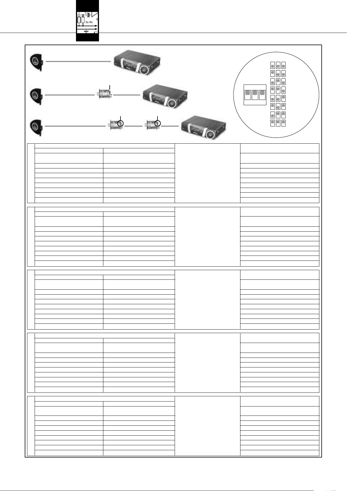
3 Puesta en funcionamiento
A
CLA
A B
CLA
A
CLA
CLA
B B
CLA
CLA
CLA
ON
1 2 3
14 dB
12 dB
10 dB
8 dB
6 dB
4 dB
2 dB
0 dB
RG58 RG213 CLA RG58 RG213 CLA RG58 RG213 CLA
53 - 57 111 - 121 0 38 - 43 79 - 89 0 41 - 46 87 - 97 0
48 - 53 100 - 111 2 33 - 38 68 - 79 2 36 - 41 76 - 87 2
43 - 48 89 - 100 4 28 - 33 58 - 68 4 31 - 36 66 - 76 4
38 - 43 79 - 89 6 23 - 28 47 - 58 6 26 - 31 55 - 66 6
GAMA I + IIGAMA III + IVGAMA V + VI
33 - 38 68 - 79 8 18 - 23 37 - 47 8 21 - 26 45 - 55 8
28 - 33 58 - 68 10 13 - 18 26 - 37 10 16 - 21 34 - 45 10
23 - 28 47 - 58 12 8 - 13 16 - 26 12 11 - 16 24 - 34 12
18 - 23 37 - 47 14 3 - 8 5 - 16 14 6 - 11 13 - 24 14
RG58 RG213 CLA RG58 RG213 CLA RG58 RG213 CLA RG58 RG213 CLA
50 - 55 105 - 115 0 36 - 40 75 - 85 0 7 - 12 15 - 25 0 39 - 44 83 - 93 0
45 - 50 95 - 105 2 31 - 36 65 - 75 2 2 - 7 5 - 15 2 35 - 39 73 - 83 2
40 - 45 85 - 95 4 26 - 31 55 - 65 4 0 - 2 4 30 - 35 63 - 73 4
36 - 40 75 - 85 6 21 - 26 45 - 55 6625 - 30 53 - 63 6
31 - 36 65 - 75 8 17 - 21 35 - 45 8820 - 25 43 - 53 8
26 - 31 55 - 65 10 12 - 17 25 - 35 10 10 15 - 20 33 - 43 10
21 - 26 45 - 55 12 7 - 12 15 - 25 12 12 11 - 15 23 - 33 12
17 - 21 35 - 45 14 2 - 7 5 - 15 14 14 6 - 11 13 - 23 14
RG58 RG213 CLA RG58 RG213 CLA RG58 RG213 CLA RG58 RG213 CLA
47 - 51 100 - 110 0 33 - 38 71 - 81 0 7 - 11 14 - 24 0 37 - 41 79 - 88 0
42 - 47 90 - 100 2 29 - 33 62 - 71 2 2 - 7 5 - 14 2 32 - 37 69 - 79 2
38 - 42 81 - 90 4 24 - 29 52 - 62 4 0 - 2 4 28 - 32 60 - 69 4
34 - 38 71 - 81 6 20 - 24 43 - 52 6623 - 28 50 - 60 6
29 - 34 62 - 71 8 16 - 20 33 - 43 8819 - 23 40 - 50 8
24 - 29 52 - 62 10 11 - 16 24 - 33 10 10 14 - 19 31 - 40 10
20 - 24 43 - 52 12 7 - 11 14 - 24 12 12 10 - 14 21 - 31 12
16 - 20 33 - 43 14 2 - 7 5 - 14 14 14 6 - 10 12 - 21 14
RG58 RG213 CLA RG58 RG213 CLA RG58 RG213 CLA
56 - 60 132 - 140 0 44 - 46 102 - 108 0 49 - 50 110 - 118 0
51 - 56 120 - 132 2 40 - 44 93 - 102 2 47 - 49 100 - 110 2
46 - 51 108 - 120 4 36 - 40 84 - 93 4 42 - 47 90 - 100 4
GAMA VII
41 - 46 97 - 108 6 32 - 36 75 - 84 6 36 - 42 81 - 90 6
36 - 41 83 - 97 8 28 - 32 66 - 75 8 31 - 36 70 - 81 8
31 - 36 71 - 83 10 25 - 28 57 - 66 10 27 - 31 60 - 70 10
26 - 31 60 - 71 12 21 - 25 48 - 57 12 23 - 27 50 - 60 12
23 - 26 52 - 60 14 18 - 21 42 - 48 14 19 - 23 44 - 50 14
RG58 RG213 CLA RG58 RG213 CLA RG58 RG213 CLA
53 - 56 122 - 131 0 40 - 44 94 - 101 0 43 - 46 102 - 107 0
48 - 53 110 - 122 2 35 - 40 82 - 94 2 38 - 43 88 - 102 2
43 - 48 99 - 110 4 30 - 35 70 - 82 4 33 - 38 76 - 88 4
GAMA VIII
38 - 43 88 - 99 6 25 - 30 58 - 70 6 28 - 33 64 - 76 6
33 - 38 79 - 88 8 22 - 25 46 - 58 8 23 - 28 52 - 64 8
28 - 33 63 - 74 10 16 - 22 34 - 46 10 18 - 23 40 - 52 10
23 - 28 50 - 63 12 11 - 16 22 - 34 12 13 - 18 28 - 40 12
20 - 23 43 - 50 14 7 - 11 15 - 22 14 10 - 13 20 - 28 14
SRA 2 B/W RA 4000 B/W
(m) (m) (dB) (m) (m) (dB) (m) (m) (dB)
SRA 2 B/W RA 4000 B/W
(m) (m) (dB) (m) (m) (dB) (m) (m) (dB) (m) (m) (dB)
SRA 2 B/W RA 4000 B/W
(m) (m) (dB) (m) (m) (dB) (m) (m) (dB) (m) (m) (dB)
SRA 2 B/W RA 4000 B/W
(m) (m) (dB) (m) (m) (dB) (m) (m) (dB)
SRA 2 B/W RA 4000 B/W
(m) (m) (dB) (m) (m) (dB) (m) (m) (dB)
A
A
A
A
A
Tabla 1: Posiciones de los interruptores CLA según el rango de frecuencias, el tipo de antena, el tipo de cable y la longitud de cable
B
B
B
B
B
44 AKG PS 4000 W
Page 45

4 Instrucciones de funcionamiento
1. Fíjese de ajustar cada canal de emisión (transmisor + receptor) en una frecuencia propia.
2. Por razones físicas,
Esto causaría ruidos.
• Para encender y apagar el sistema, respete siempre la secuencia indicada en los capítulos 4.2 y 4.3, para evitar daños
por sobrecarga de la alimentación de energía eléctrica del divisor de antenas.
1. Encienda los transmisores.
2. Encienda todos los receptores conectados al divisor de antenas.
3. Encienda el divisor de antenas pulsando la tecla ON/OFF.
Los LEDs OK azules del divisor de antenas y los LEDs de control verdes de los componentes activos conectados empiezan a
emitir luz.
1. Apague todos los receptores conectados al divisor de antenas.
2. Apague los transmisores.
3. Apague el divisor de antenas pulsando la tecla ON/OFF.
Los LEDs OK azules del divisor de antenas y los LEDs de control verdes de los componentes activos conectados dejan de emitir luz.
1. Encienda la unidad de alimentación central PSU 4000.
2. Encienda los transmisores.
3. Encienda el divisor de antenas pulsando la tecla ON/OFF.
Los LEDs OK azules del divisor de antenas y los LEDs de control verdes de los componentes activos conectados empiezan a
emitir luz.
4. Encienda todos los receptores conectados al divisor de antenas.
1. Apague todos los receptores conectados al divisor de antenas.
2. Apague los transmisores.
3. Apague el divisor de antenas pulsando la tecla ON/OFF.
Los LEDs OK azules del divisor de antenas y los LEDs de control verdes de los componentes activos conectados dejan de emitir luz.
4. Apague la unidad de alimentación central PSU 4000.
no debe operar más de un canal de emisión en la misma frecuencia al mismo tiempo y en el mismo lugar.
44..11 IInnssttrruucccciioonneess ggeenneerraalleess
¡¡IImmppoorrttaannttee!!
!
L
44..22 SSiisstteemmaass ccoonn aalliimmeennttaacciióónn
ddeesscceennttrraalliizzaaddaa
44..22..11 EEnncceennddeerr
44..22..22 AA ppaaggaarr
44..33 SSiisstteemmaass ccoonn aalliimmeennttaacciióónn
cceennttrr aall PPSSUU 44000000 ooppcciioonnaall
44..33..11 EEnncceennddeerr
44..33..22 AA ppaaggaarr
5 Limpieza
• Para limpiar las superficies del divisor de antenas, lo mejor es utilizar un paño humedecido en agua.
6 Solución de errores
Error Posible causa Solución
No hay sonido.
En canales determinados no hay recepción
o está perturbada:
1. Los adaptadores de red/la(s) PSU 4000 no están
conectados al tomacorriente.
2. Los cables DC no están conectados o están averiados.
3. Las antenas no están conectadas.
4. El(los) adaptador(es) de red/la(s) PSU 4000 están averiados.
1. El transmisor y/o el receptor no está(n) encendido(s).
2. Las pilas del transmisor están vacías.
3. El adaptador de red o el cable de conexión del
PSU 4000 al receptor
a) tienen un contacto malo o
b) están defectuosos.
4. El transmisor y receptor del canal correspondiente no
están ajustados en la misma frecuencia.
5. El transmisor o el receptor está fallado.
1. Conecte los adaptadores de red/la(s) PSU 4000 al
tomacorriente.
2. Conecte los cables DC o reemplácelos.
3. Conecte las antenas.
4. Contacte con su Centro de Servicio AKG.
1. Encenda el transmisor y/o receptor.
2. Cambie las pilas del transmisor.
3. a) Verifique el asiento seguro del conector del adapta-
dor de red o del cable de conexión, o
b) reemplace el adaptador de red o el cable de cone-
xión.
4. Ajuste el transmisor y el receptor en la misma frecuencia. Sírvase leer el Modo de Empleo del transmisor y del receptor.
5. Diríjase al distribuidor AKG.
El LED verde de un componente activo de antena
no emite luz.
Uno de los LEDs ERROR del divisor de antenas
emite luz.
1. El cable de antena no está conectado o el contacto es
malo.
2. El cable de antena está averiado.
3. El componente activo de antena está averiado.
1. La tensión de alimentación de los componentes de
antena activos está cortocircuitada.
1. Conecte el cable de antena o verifique que esté bien
conectado.
2. Reemplace el cable de antena.
3. Contacte con su Centro de Servicio AKG.
1. Verifique todos los cables y componentes de antena
activos conectados. Reemplace los cables y/o componentes averiados.
AKG PS 4000 W 45
Page 46

6 Solución de errores
Error Posible causa Solución
Uno de los LEDs ERROR del divisor de antenas
emite luz.
2. La tensión de alimentación de los componentes de
antena activos es muy baja porque las longitudes de
cable son muy grandes.
2. Verifique que las longitudes de los cables conectados
7 Datos técnicos
Divisor de antenas PS 4000 W
Tipo: 2 x 1 salidas para 4 + 2 x 1 PS (pueden conectarse en cascada)
Banda de frecuencias portadoras: 500 - 865 MHz
Atenuación: 0, 2, 4, 6, 8, 10, 12, 14 dB, conmutable
Entradas de alta frecuencia: 2 conectores hembra BNC, 50 Ohm
Salidas de alta frecuencia: 10 conectores hembra BNC, 50 Ohm
Tensión de alimentación: 12 V DC
Medidas: 200 x 190 x 44 mm
Peso: apróx. 970 g
Amplificador de antena AB 4000
Banda de frecuencias portadoras: 500 - 865 MHz
Amplificación: apróx. 17 - 3,5 dB. conmutable
Entrada de alta frecuencia: 1 conector hembra BNC, 50 Ohm
Salida de alta frecuencia: 1 conector hembra BNC, 50 Ohm
Tensión de alimentación: 8 V DC, a través de cable de antena de PS 4000 W ó ASU 4000
Medidas: 110 x 35 mm
Peso: apróx. 150 g
sean las indicadas en la Tabla 1. Utilice cables más
cortos o divida los cables y conecte entremedio una
ASU 4000 (ver también los diagramas de cableado).
Antena omnidireccional activa RA 4000 B/W
Banda de frecuencias portadoras: 500 - 865 MHz
Ganancia y amplificación: 17 dB
Entrada de alta frecuencia: 1 conector hembra BNC, 50 Ohm
Salida de alta frecuencia: 1 conector hembra BNC, 50 Ohm
Tensión de alimentación: 8 V DC, a través de cable de antena de PS 4000 W ó ASU 4000
Medidas: 235 x 38,5 mm
Peso: 65 g
Antena direccional activa SRA 2 B/W
Banda de frecuencias portadoras: 500 - 865 MHz
Ganancia y amplificación: 21,5 dB
Ángulo de abertura: 70°
Medidas: 230 x 240 x 26 mm
Peso: apróx. 250 g
Unidad de alimentación remota ASU 4000
Banda de frecuencias portadoras: 500 - 865 MHz
Entrada de alta frecuencia: 1 conector hembra BNC, 50 Ohm
Salida de alta frecuencia: 1 conector hembra BNC, 50 Ohm
Tensión de alimentación: 12 V DC
Medidas: 78 x 50 x 50 mm
Peso: 150 g
Este aparato corresponde a las normas citadas en la declaración de conformidad. Esta última está disponible en el sitio http://www.akg.com o puede ser solicitada al correo electrónico sales@akg.com.
46 AKG PS 4000 W
Page 47

Índice
1 Segurança e meio ambiente. . . . . . . . . . . . . . . . . . . . . . . . . . . . . . . . . . . . . . . . . . . . . . . . . . . . . . . . . . . . . 47
1.1 Segurança . . . . . . . . . . . . . . . . . . . . . . . . . . . . . . . . . . . . . . . . . . . . . . . . . . . . . . . . . . . . . . . . . . . . . . . 47
1.2 Meio ambiente. . . . . . . . . . . . . . . . . . . . . . . . . . . . . . . . . . . . . . . . . . . . . . . . . . . . . . . . . . . . . . . . . . . . 47
2 Apresentação . . . . . . . . . . . . . . . . . . . . . . . . . . . . . . . . . . . . . . . . . . . . . . . . . . . . . . . . . . . . . . . . . . . . . . . 48
2.1 Introdução . . . . . . . . . . . . . . . . . . . . . . . . . . . . . . . . . . . . . . . . . . . . . . . . . . . . . . . . . . . . . . . . . . . . . . . 48
2.2 Conteúdo da embalagem . . . . . . . . . . . . . . . . . . . . . . . . . . . . . . . . . . . . . . . . . . . . . . . . . . . . . . . . . . . . 48
2.3 Acessórios opcionais . . . . . . . . . . . . . . . . . . . . . . . . . . . . . . . . . . . . . . . . . . . . . . . . . . . . . . . . . . . . . . . 48
2.4 Apresentação. . . . . . . . . . . . . . . . . . . . . . . . . . . . . . . . . . . . . . . . . . . . . . . . . . . . . . . . . . . . . . . . . . . . . 48
2.4.1 Placa frontal . . . . . . . . . . . . . . . . . . . . . . . . . . . . . . . . . . . . . . . . . . . . . . . . . . . . . . . . . . . . . . . . . 48
2.4.2 Lado traseiro. . . . . . . . . . . . . . . . . . . . . . . . . . . . . . . . . . . . . . . . . . . . . . . . . . . . . . . . . . . . . . . . . 49
2.5 Alimentação de corrente central PSU 4000 (opcional). . . . . . . . . . . . . . . . . . . . . . . . . . . . . . . . . . . . . . . 49
2.6 Antenas de recepção (opcionais). . . . . . . . . . . . . . . . . . . . . . . . . . . . . . . . . . . . . . . . . . . . . . . . . . . . . . . 49
2.6.1 SRA 2 B/W . . . . . . . . . . . . . . . . . . . . . . . . . . . . . . . . . . . . . . . . . . . . . . . . . . . . . . . . . . . . . . . . . . 49
2.6.2 RA 4000 B/W . . . . . . . . . . . . . . . . . . . . . . . . . . . . . . . . . . . . . . . . . . . . . . . . . . . . . . . . . . . . . . . . 49
3 Operação. . . . . . . . . . . . . . . . . . . . . . . . . . . . . . . . . . . . . . . . . . . . . . . . . . . . . . . . . . . . . . . . . . . . . . . . . . . . 50
3.1 Montagem dum splitter de antenas num rack . . . . . . . . . . . . . . . . . . . . . . . . . . . . . . . . . . . . . . . . . . . . . 50
3.2 Montagem de dois splitters de antenas lado a lado . . . . . . . . . . . . . . . . . . . . . . . . . . . . . . . . . . . . . . . . . 50
3.3 Montagem das antenas . . . . . . . . . . . . . . . . . . . . . . . . . . . . . . . . . . . . . . . . . . . . . . . . . . . . . . . . . . . . . 50
3.3.1 Lugar de montagem . . . . . . . . . . . . . . . . . . . . . . . . . . . . . . . . . . . . . . . . . . . . . . . . . . . . . . . . . . . 50
3.3.2 Montagem em um tripé de chão . . . . . . . . . . . . . . . . . . . . . . . . . . . . . . . . . . . . . . . . . . . . . . . . . . 50
3.3.3 Montagem em paredes/tetos . . . . . . . . . . . . . . . . . . . . . . . . . . . . . . . . . . . . . . . . . . . . . . . . . . . . . 50
3.4 Ligar as antenas . . . . . . . . . . . . . . . . . . . . . . . . . . . . . . . . . . . . . . . . . . . . . . . . . . . . . . . . . . . . . . . . . . 51
3.4.1 Sistema monocanal com antenas passivas. . . . . . . . . . . . . . . . . . . . . . . . . . . . . . . . . . . . . . . . . . . 51
3.4.2 Sistema monocanal com antenas ativas. . . . . . . . . . . . . . . . . . . . . . . . . . . . . . . . . . . . . . . . . . . . . 51
3.5 Sistemas multicanais com splitter de antenas PS 4000 W . . . . . . . . . . . . . . . . . . . . . . . . . . . . . . . . . . . . 51
3.6 Comutador CLA . . . . . . . . . . . . . . . . . . . . . . . . . . . . . . . . . . . . . . . . . . . . . . . . . . . . . . . . . . . . . . . . . . . 52
4 Dicas para a operação . . . . . . . . . . . . . . . . . . . . . . . . . . . . . . . . . . . . . . . . . . . . . . . . . . . . . . . . . . . . . . . . . 54
4.1 Avisos gerais . . . . . . . . . . . . . . . . . . . . . . . . . . . . . . . . . . . . . . . . . . . . . . . . . . . . . . . . . . . . . . . . . . . . . 54
4.2 Sistemas com alimentação de corrente decentralizada. . . . . . . . . . . . . . . . . . . . . . . . . . . . . . . . . . . . . . . 54
4.2.1 Ligar . . . . . . . . . . . . . . . . . . . . . . . . . . . . . . . . . . . . . . . . . . . . . . . . . . . . . . . . . . . . . . . . . . . . . . 54
4.2.2 Desligar . . . . . . . . . . . . . . . . . . . . . . . . . . . . . . . . . . . . . . . . . . . . . . . . . . . . . . . . . . . . . . . . . . . . 54
4.3 Sistemas com alimentação de corrente central opcional PSU 4000 . . . . . . . . . . . . . . . . . . . . . . . . . . . . . 54
4.3.1 Ligar . . . . . . . . . . . . . . . . . . . . . . . . . . . . . . . . . . . . . . . . . . . . . . . . . . . . . . . . . . . . . . . . . . . . . . 54
4.3.2 Desligar . . . . . . . . . . . . . . . . . . . . . . . . . . . . . . . . . . . . . . . . . . . . . . . . . . . . . . . . . . . . . . . . . . . . 54
5 Limpeza . . . . . . . . . . . . . . . . . . . . . . . . . . . . . . . . . . . . . . . . . . . . . . . . . . . . . . . . . . . . . . . . . . . . . . . . . . . . 54
6 Como resolver problemas. . . . . . . . . . . . . . . . . . . . . . . . . . . . . . . . . . . . . . . . . . . . . . . . . . . . . . . . . . . . . . . 54
7 Especificações . . . . . . . . . . . . . . . . . . . . . . . . . . . . . . . . . . . . . . . . . . . . . . . . . . . . . . . . . . . . . . . . . . . . . . . 55
Fig. 8 a 13. . . . . . . . . . . . . . . . . . . . . . . . . . . . . . . . . . . . . . . . . . . . . . . . . . . . . . . . . . . . . . . . . . . . . . . . . . . . . . 56
1. Não derrame líquidos sobre o dispositivo e não deixe cair qualquer objeto dentro dos orifícios de ventilação.
2. O aparelho deverá ser operado só em área seca.
3. Cabe exclusivamente aos técnicos autorizados abrir e consertar o aparelho e efetuar trabalhos de manutenção no mesmo. No
interior do aparelho não há componentes em que leigos poderiam efetuar trabalhos de manutenção, ou que poderiam trocar ou
reparar.
4. Antes de ligar o aparelho certifique-se que a tensão indicada no alimentador fornecido na embalagem corresponde à tensão da
rede no lugar de aplicação.
5. Utilize o aparelho apenas com o alimentador de tensão alternada fornecido na embalagem com uma tensão de saída de 12 V
c.c.! Outros tipos de corrente assim como tensões diferentes poderão provocar avarias severas no aparelho!
6. Desligue a instalação imediatamente se tiver entrado líquido ou um objeto sólido dentro do aparelho. Neste caso tire imediatamente o alimentador da tomada de rede e mande controlar o aparelho pelo nosso serviço técnico.
7. Quando não utilizar o aparelho durante um período mais prolongado, desconecte o alimentador da tomada de rede. Repare que
o aparelho desligado não está completamente desconectado da rede quando o alimentador ainda se encontrar na tomada.
8. Não posicione o dispositivo perto de fontes de calor, por exemplo, radiadores, tubos de calefação, amplificadores, etc., e não
exponha o dispositivo à radiação solar, poeira ou umidade, chuva, vibrações e golpes.
9. Para evitar interferências ou anormalidades é preciso instalar todos os cabos de áudio, particularmente os cabos das entradas
de microfone, separados de linhas de alta tensão e de rede. Quando os instalar em condutos de cabo é preciso colocar as linhas
de áudio num canal separado.
10. Para limpar o aparelho use um pano úmido mas não molhado. Primeiro tire o alimentador da tomada de rede! Não utilize detergentes abrasivos ou acres nem líquidos que contenham álcool ou dissolventes, porque estes poderão prejudicar o esmalte e as
partes de material sintético.
11. Utilize o aparelho exclusivamente para os fins descritos neste manual. A AKG não se responsabiliza por danos provocados por
uso impróprio ou operação errada.
!
L
11..11 SSeegguurraannççaa
1. Mesmo se o aparelho estiver desligado, o alimentador consome energia elétrica em quantidades reduzidas. Para poupar energia, tire o cabo de força do alimentador da tomada de rede se não utilizar o aparelho durante um período mais prolongado.
2. Quando pretende desfazer-se do aparelho, remova as pilhas ou os acumuladores, separe a carcaça, a eletrônica e os cabos e
providencie que estes serão eliminados conforme as normas estabelecidas por lei.
3. A embalagem é reciclável. Elimine a embalagem num sistema de colheita apropriado.
11..22 MMeeiioo aammbbiieennttee
AKG PS 4000 W 47
Page 48

2 Apresentação
22..11 II nnttrroodduuççããoo
22..22 VVoolluummee ddee ffoorrnneecciimmeennttoo
22..33 AAcceessssóórriiooss ooppcciioonnaaiiss
Agradecemos a sua preferência por um produto da AKG. Por favor reserve alguns minutos para ler este manual antes de acionar
este equipamento e guarde as instruções cuidadosamente para sempre poder consultá-las em caso de aparecerem quaisquer per-
guntas. Divirta-se e bom trabalho!
1 splitter de antenas PS 4000 W 1 set de montagem 19”
Verifique se a embalagem contém todos os componentes acima indicados. Caso falte algo, favor entre em contato com a concessionária da AKG.
• Adaptador de força (12 V DC)
• Antena direcional ativa SRA 2 B/W
• Antena ativa omnidirecional RA 4000 B/W
• Cabos de antena MK PS
• Alimentação central de corrente PSU 4000
• Alimentador remoto ASU 4000
22..44 AApprreesseennttaaççããoo
22..44..11 PPllaaccaa ffrroonnttaall
Fig. 1: A placa frontal do PS 4000 W
• Amplificador de antena AB 4000
O splitter de antenas PS 4000 W é um distribuidor de antenas para montar um sistema multicanal UHF com até quatro receptores
por cada splitter (a verdadeira quantidade de canais que podem ser operados simultaneamente depende do plano de freqüências
do país onde é aplicado).
O PS 4000 W possui duas entradas de antena, às quais pode conectar antenas de recepção ativas tipo SRA 2 B/W ou
RA 4000 B/W com booster integrado (amplificador de antena). As entradas de antena disponibilizam uma tensão de alimentação de
12 V DC para três componentes ativos de antena no máximo, por exemplo, uma antena ativa e dois amplificadores de antena
AB 4000. Além disso, no lado traseiro estão disponíveis 2 x 4 saídas de antena para até 4 receptores diversity, assim como duas
saídas de antenas adicionais para transferir o sinal de antena a mais splitters de antenas PS 4000 W adicionais.
O PS 4000 W possui uma carcaça robusta de metal duma altura de 1 U e uma largura de metade de 19“. Desta forma pode montar dois splitters de antenas lado a lado num nível de rack.
A alimentação de corrente do PS 4000 W é efetuada através dum adaptador de força opcional. Para os sistemas que possuam mais
de 4 canais recomendamos a alimentação de corrente central opcional PSU 4000 para três splitters de antenas a cada uma.
Não só os amplificadores de antena, mas também o splitter de antenas são aparelhos de banda larga para toda a banda de freqüência UHF.
Na placa frontal do splitter de antenas encontram-se os seguintes elementos de controle e indicação:
ON/OFF: Chave liga/desliga. Pressione a tecla para ligar o aparelho. Para desligar pressione a tecla de novo.
ANTENNA A, ANTENNA B: O LED azul de OK acende-se quando na entrada de antena ANTENNA A IN/ANTENNA B IN há a tensão
correta para os componentes ativos.
Caso houver curto-circuito numa entrada de antena ou se cair a alimentação de corrente (para um valor abaixo de 2 V), o respectivo LED OK apagar-se-á e acender-se-á o LED vermelho ERROR.
OObbsseerrvvaaççããoo::
Veja tabela 1 na página 53.
• Os LEDs OK NÃO indicam o estado de operação do respectivo amplificador de antena e não se apagarão quando retirar um cabo
de antena.
CLA: Por baixo da tampa com o logotipo da AKG encontra-se um grupo de três chaves DIP para adaptar as entradas de antena
(ANTENNA A IN, ANTENNA B IN) a comprimentos diferentes de cabos de antena.
48 AKG PS 4000 W
Page 49

No lado traseiro do PS 4000 W estão disponíveis as seguintes entradas e saídas:
2 Apresentação
22..44..22 LLaaddoo ttrraasseeiirroo
Fig. 2: Lado traseiro do PS 4000 W
DC IN 12 V/2
ANTENNA A IN, ANTENNA B IN: Entradas BNC para as antenas de recepção separadas SRA 2 B/W ou RA 4000 B/W. Visto que o
ANTENNA A OUT TO SR: Nas quatro saídas BNC 1A a 4A está disponível o sinal de antena para o componente de recepção A de
ANTENNA B OUT TO SR: Nas quatro saídas BNC 1B a 4B está disponível o sinal de antena para o componente de recepção B de
• A corrente nas saídas 1A a 4B é suficiente para a alimentação só se conectar o splitter de antenas à alimentação cen-
• Se usar o splitter de antenas PS 4000 W com um alimentador de força separado (opcional), deverá operar também
LINK A TO PS, LINK B TO PS: Nestas saídas BNC está disponível o sinal RF das duas antenas A e B. Pode ligar os conectores LINK
A alimentação de corrente central PSU 4000 fornece uma tensão secundária de 12 V DC, 2 A para três splitters de antenas
PS 4000 W e os receptores ligados aos mesmos (12 no máximo). Para informações mais detalhadas leia o manual do PSU 4000.
Para o sistema de antenas PS 4000 W estão disponíveis antenas direcionais passivas e ativas tal como antenas omnidirecionais
passivas e ativas. Todas as antenas são antenas de banda larga para toda a banda de freqüências UHF.
As antenas ativas são alimentadas de corrente pelo splitter de antenass PS 4000 W através dos cabos de antena. Em sistemas complexos com cabos compridos de antena recomendamos operar as antenas ativas com uma alimentação central de corrente
PSU 4000 através de um alimentador remoto ASU 4000 para cada uma das antenas.
A: Entrada para um adaptador de força com tensão secundária de 12 V DC (opcional) ou a alimentação de corrente
central opcional PSU 4000.
receptor funciona com técnica diversity, necessita de duas antenas de recepção (não estão incluídas na embalagem). As entradas de antena disponibilizam uma tensão de alimentação de 12 V DC para antenas ativas.
até quatro receptores diversity. A elétrica de todas saídas não usadas será fechada automaticamente.
até quatro receptores diversity. A elétrica de todas saídas não usadas será fechada automaticamente.
Além do sinal de antena, as saídas 1A a 4A e 1B a 4B fornecem uma tensão de alimentação de 12 V DC para os receptores
ligados.
tral opcional PSU 4000.
todos os receptores com adaptador de força separado (opcional também). Se ligar os receptores ao splitter de antenas sem adaptador de força, o adaptador de força do splitter de antenas poderá levar a prejuízos causados pela sobrecarga.
às entradas de antena de um outro splitter de antenas PS 4000 W. Desta forma pode ligar em cascata vários splitters de antenas PS 4000 W.
Repare que para cada três splitters de antenas PS 4000 W é necessária uma alimentação central opcional PSU 4000.
IImmppoorrttaannttee!!
!
L
Veja também diagramas de cablagem
Fig. 10 a
Fig. 13.
22..55 AAlliimmeennttaaççããoo ddee ccoorrrreennttee cceennttrraall
PPSSUU 44000000 ((ooppcciioonnaall))
22..66 AAnntteennaass ddee rreecceeppççããoo ((ooppcciioonnaall))
A SRA 2 B/W é uma antena direcional ativa com carcaça robusta e impermeável, destinando-se à aplicação em prédios ou no ar
livre. É especialmente adaptada á montagem distante ao lugar de atuação. Um amplificador de alta potência integrado possibilita
instalar a antena a uma distância de até 100 m do receptor. Com os cabos de antena RG213 e um ou dois amplificadores AB 4000
em série pode posicionar a SRA 2 B/W a uma distância de até 200 m do receptor.
A antena está provida de uma saída BNC, um LED de controle de função, e uma conexão integrada para tripés. Um ponteiro de laser
opcional facilita direcionar a antena com exatidão ao lugar de atuação.
A RA 4000 B/W é uma antena omnidirecional ativa com carcaça robusta e impermeável que se destina à aplicação em prédios ou
no ar livre. É especialmente adaptado á montagem próxima ao lugar de atuação. Um amplificador de antena de alta potência integrado possibilita instalar a antena a uma distância de até 100 m do receptor. Com cabos de antena RG213 e um ou dois amplificadores AB 4000 em série pode posicionar a RA 4000 B/W a uma distância de até 200 m do receptor.
A antena está provida de uma saída BNC, um LED de controle de função, e uma conexão integrada para tripés.
22..66..11 SSRRAA 22 BB//WW
22..66..22 RRAA 44000000 BB//WW
AKG PS 4000 W 49
Page 50

3 Operação
33..11 MM oonnttaaggeemm dduumm sspplliitttteerr
ddee aanntteennaass nnuumm rraacckk
Veja fig. 8.
33..22 MM oonnttaaggeemm ddee ddooiiss sspplliitttteerrss
ddee aanntteennaass llaaddoo aa llaaddoo nnuumm rraacckk
Veja fig. 9.
OObbsseerrvvaaççããoo::
33..33 MM oonnttaaggeemm ddaass aanntteennaass
33..33..11 LLuuggaarr ddee mmoonnttaaggeemm
1. Desenrosque os quatro pés de borracha (1) do lado inferior do splitter de antenas.
2. Desenrosque os dois parafusos de fixação (2) de cada uma das duas placas laterais.
3. Fixe com os parafusos (2) o ângulo curto de fixação (3) numa das placas laterais e o ângulo longo de montagem (4) do set de
montagem incluído na embalagem na outra placa lateral.
4. Fixe o splitter de antenas no rack.
1. Desenrosque os quatro pés de borracha (1) do lado inferior dos dois splitters de antenas e retire os parafusos (5) dos pés de
borracha (1).
2. Desenrosque os dois parafusos de fixação (2) da placa lateral direita de um splitter de antenas e da placa lateral esquerda do
outro splitter de antenas.
3. Retire as tampas de plástico (3) daquelas placas laterais das quais não retirou os parafusos de fixação (2).
4. Insira uma conexão (4) em cada um dos entalhes livres na placa lateral do primeiro splitter de antenas de maneira que a abertura da conexão se alinhe com a abertura roscada no lado inferior do splitter de antenas.
5. Fixe as duas conexões (4) com dois parafusos (5) (tirados dos pés de borracha) no primeiro splitter de antenas.
6. Conecte os dois splitters de antenas inserindo as conexões (4) do primeiro splitter de antenas nos entalhes livres da placa lateral do segundo splitter de antenas até a abertura em ambas as conexões (4) se alinhar com a respectiva abertura roscada no
lado inferior do segundo splitter de antenas.
7. Fixe as conexões (4) com dois parafusos (5) retirados dos pés de borracha (1) no segundo splitter de antenas.
8. Fixe um ângulo de montagem curto (6) com dois parafusos (2) das placas laterais na placa lateral externa de cada splitter de
antenas.
9. Fixe os splitters de antenas no rack.
• Guarde os parafusos restantes (5) para poder usá-los depois.
Os seguintes avisos para a montagem das antenas aplicam-se a todos os sistemas monocanais e multicanais independentemente
da quantidade de canais.
As reflexões do sinal do emissor em superfícies de metal, paredes, tetos, etc. ou efeitos de sombra do corpo humano poderão enfraquecer ou eliminar o sinal do emissor. Por isso posicione as antenas da forma seguinte:
1. Coloque as antenas sempre perto do âmbito de ação (palco), mas mantenha uma distância mínima de 5 m entre o emissor e
as antenas e uma distância mínima de 20 cm entre as duas antenas.
2. O contato visual é importante para uma recepção adequada.
3. Posicione as antenas a uma distância de mais de 1,5 m de objetos de metal grandes, arame (malha) ou chapas de metal, assim
como paredes, andaimes de palco e tetos, etc.
4. Não coloque as antenas em nichos de parede.
5. Coloque as antenas a uma distância de 1,5 m de objetos emissores de RF como racks de luz, lâmpadas fluorescentes, aparelhos de efeitos digitais e computadores.
6. Se montar duas antenas uma ao lado da outra, certifique-se de que a distância entre as duas antenas é de 20 cm no mínimo.
33..33..22 MMoonnttaaggeemm nnuumm ttrriippéé ddee cchhããoo
Fig. 3: Antena fixada num tripé de chão
33..33..33 MMoonnttaaggeemm eemm ppaarreeddeess//tteettooss
Fig. 4: Distância mínima
de superfícies planas
≥ 70c m
˛
˛
Se colocar a antena em tripés de chão, observe os seguintes avisos:
1. Fixe no braço do tripé de girafa a antena com a conexão para tripé SA 63 que
está incluída na embalagem ou com a conexão para tripé integrada.
˛
2. Puxe o braço para um lado para que a antena se encontre a uma distância de
70 cm do tripé no mínimo.
3. Estenda o tripé de maneira que o braço se encontre a uma distância de 1,8 m
acima do chão.
≥ 180cm
˛
4. Enrole o cabo de antena em torno do braço. O cabo não deverá pender, porque
isto poderá prejudicar a qualidade de recepção.
Se fixar a antena na parede ou no teto, observe as seguintes distâncias mínimas:
˛
≥ 10cm
˛
˛
˛
˛
˛
≥ 50c m≥ 50c m
1. Monte a antena a uma distância direta de pelo menos 10 cm ou a uma distância lateral de pelo menos 50 cm de paredes ou outras superfícies planas, ou de
grades e andaimes de metal.
50 AKG PS 4000 W
Page 51

3 Operação
˛
≥ 50 (15) cm
˛
˛
≥ 15cm
˛
Para um sistema monocanal um splitter não é necessário. Pode ligar as antenas diretamente ao receptor.
Antena
AA BB BB
Antena
AA::
RG58: 0 - 13 m / RG213: 5 - 26 m
BB::
RG58: 6 - 46 m / RG213: 12 - 97 m
1. Verifique as distâncias dos cabos entre o receptor e as duas antenas.
2. Leia na tabela 1 da página 53, se precisa de dividir a distância total em vários cabos e se precisa de um ou mais amplificadores de antena AB 4000. A tabela 1 indica o comprimento máximo permitido conforme o tipo do cabo.
3. Ligue a cada antena um cabo de antena.
4. Ligue as duas antenas às entradas de antena no receptor conforme a tabela 1.
Se precisar de um ou dois amplificadores de antena AB 4000, deverá inserir na linha um alimentador remoto ASU 4000 entre
o receptor e o primeiro amplificador.
RG58: 0 - 13 m / RG213: 5 - 26 m
AABB 44000000
2. Certifique-se de que a antena se encontra a uma distância de pelo menos 15 cm
do solo e de 50 cm (15 cm se o cabo estiver conduzido de cima) do teto.
Fig. 5: Distância mínima do solo e do teto
<<-- DDCC//AACC -->>
<<-- DDCC//AACC -->>
AABB 44000000
RReecceeppttoorr
AASSUU 44000000
33..44 LLiiggaarr aass aanntteennaass
33..44..11 SSiisstteemmaa mmoonnooccaannaall
ccoomm aanntteennaass ppaassssiivvaass
Veja tabela 1 na página 53 e fig. 6.
Fig. 6:
Cablagem dum sistema monocanal
com antenas passivas e linhas de antenas
de comprimentos diferentes
Veja fig. 6.
5. Verifique se a tensão de rede indicada nos adaptadores de força do ASU 4000 e do receptor corresponde à tensão de
rede no lugar de aplicação. Se usar os adaptadores de força com uma tensão de rede diferente, isto poderá levar a
prejuízos no aparelho.
6. Ligue o alimentador remoto e o receptor aos adaptadores de força e cada adaptador de força a uma tomada adequada.
<<-- DDCC//AACC -->>
SRA 2 B/W
RG58: 0 - 13 m / RG213: 5 - 26 m
AABB 44000000
AA BB BB
SRA 2 B/W
1. Verifique as distâncias dos cabos entre o receptor e as duas antenas ativas.
2. Leia na tabela 1 da página 53, se precisa de dividir a distância total em vários cabos e se precisa de um ou dois amplificado-
3. Ligue a cada antena um cabo de antena.
4. Conecte conforme a tabela 1 as antenas com um ou dois amplificador(es) AB 4000, a um alimentador ASU 4000 para cada
5. Verifique se a tensão de rede indicada nos adaptadores de força dos dois ASU 4000 e do receptor corresponde à ten-
6. Ligue os alimentadores remotos e o receptor aos adaptadores de força e cada adaptador de força a uma tomada adequada.
Exemplos para a cablagem de sistemas multicanais encontrará na fig. 10 a 13 na página 56.
Na montagem de um sistema multicanal observe os seguintes itens:
AA::
RG58: 0 - 13 m / RG213: 5 - 26 m
BB::
RG58: 6 - 46 m / RG213: 12 - 97 m
res de antena AB 4000. A tabela 1 indica o comprimento máximo permitido conforme o tipo do cabo.
antena e com as entradas de antena do receptor.
são de rede no lugar de aplicação. Se usar os adaptadores de força com uma tensão de rede diferente poderá levar
a prejuízos no aparelho.
AABB 44000000 AASSUU 44000000
AASSUU 44000000
RReecceeppttoorr
<<-- DDCC//AACC -->>
<<-- DDCC//AACC -->>
IImmppoorrttaannttee!!
!
L
33..44..22 SSiisstteemmaa mmoonnooccaannaall
ccoomm aanntteennaass aattiivvaass
Veja tabela 1 na página 53 e fig. 7.
Cablagem dum sistema monocanal
Fig. 7:
com antenas ativas e linhas de antenas de
comprimentos diferentes
Veja fig. 7.
IImmppoorrttaannttee!!
!
L
33..55 SSiisstteemmaass mmuullttiiccaannaaiiss
ccoomm sspplliitttteerr ddee aanntteennaass PPSS 44000000 WW
1. Pode ligar ao splitter de antenas PS 4000 W até quatro receptores.
• Se usar o splitter de antenas e também os receptores com um respectivo adaptador de força separado (opcional), é
necessário ligar primeiro os adaptadores de força dos receptores à rede, antes de ligar o adaptador de força do splitter de antenas à rede.
Se ligar primeiro o splitter de antenas à rede, o adaptador de força do splitter de antenas poderá sofrer prejuízos em
virtude da carga dos receptores.
!
L
AAvviissoo!!
AKG PS 4000 W 51
Page 52

3 Operação
2. Em os sistemas maiores com até 50 canais pode interconectar a respectiva quantidade de splitters de antenas:
• Ligue os conectores LINK do primeiro splitter de antenas às respectivas entradas ANTENNA IN do próximo splitter de antenas e assim por diante.
• Para a alimentação de corrente deste tipo de sistema recomendamos a alimentação de corrente central PSU 4000 para três
splitters de antenas e quatro receptores.
3. Cada entrada de antena do splitter de antenas é capaz de fornecer através dos cabos de antena corrente a três componentes
ativos (por exemplo 1 x RA 4000 B/W + 2 x AB 4000) no máximo.
Nos seguintes casos necessita do alimentador remoto ASU 4000 para a alimentação dos componentes ativos (o ASU 4000 é
capaz de alimentar também três componentes ativos):
• A distância dos cabos entre o splitter de antenas e o componente ativo possui um comprimento que faz cair a tensão de
alimentação para um valor abaixo do mínimo permitido.
• Entre o PS 4000 W e o componente ativo encontra-se um aparelho (por exemplo um combiner* de antenas), que interrom-
pe a tensão de alimentação DC no cabo de antena.
OObbsseerrvvaaççããoo::
33..66 CCoommuuttaaddoorr CCLLAA
Veja tabela 1 na página 53.
* O combiner de antenas ZAPD 21 da empresa Mini Circuit deixa passar a tensão de alimentação. Com os outros produtos
isto não é garantido.
• Ligou duas linhas de antena a uma entrada de antena através dum combiner. Se operar numa linha de antena três ou mais
componentes ativos, será preciso interpor um alimentador remoto ASU 4000 entre o combiner de antena e o primeiro destes componentes ativos. Se operar mais de três componentes ativos nas duas linhas de antena, necessitará para cada linha
de antena um alimentador remoto ASU 4000. O alimentador remoto é necessário para evitar a sobrecarga da alimentação
de corrente do splitter de antenas.
O nível do sinal RF em cada entrada de antena do(s) splitter(s) de antenas depende da banda de freqüências, do tipo de antena, do
tipo do cabo, e do comprimento do cabo.
Para garantir o melhor nível de sinal RF na entrada de antena, é preciso ajustar o comutador CLA em cada amplificador de antena
e no(s) splitter(s) de antenas conforme a tabela 1.
1. Retire a tampa do comutador CLA.
2. Ajuste as chaves DIP conforme a banda de freqüências, tipo de antena, tipo do cabo e comprimento do cabo.
3. Recoloque a tampa.
52 AKG PS 4000 W
Page 53

A
CLA
A B
CLA
A
CLA
CLA
B B
3 Operação
CLA
CLA
CLA
ON
1 2 3
14 dB
12 dB
10 dB
8 dB
6 dB
4 dB
2 dB
0 dB
RG58 RG213 CLA RG58 RG213 CLA RG58 RG213 CLA
53 - 57 111 - 121 0 38 - 43 79 - 89 0 41 - 46 87 - 97 0
48 - 53 100 - 111 2 33 - 38 68 - 79 2 36 - 41 76 - 87 2
43 - 48 89 - 100 4 28 - 33 58 - 68 4 31 - 36 66 - 76 4
38 - 43 79 - 89 6 23 - 28 47 - 58 6 26 - 31 55 - 66 6
BANDAS I + IIBANDAS III + IVBANDAS V + VI
33 - 38 68 - 79 8 18 - 23 37 - 47 8 21 - 26 45 - 55 8
28 - 33 58 - 68 10 13 - 18 26 - 37 10 16 - 21 34 - 45 10
23 - 28 47 - 58 12 8 - 13 16 - 26 12 11 - 16 24 - 34 12
18 - 23 37 - 47 14 3 - 8 5 - 16 14 6 - 11 13 - 24 14
RG58 RG213 CLA RG58 RG213 CLA RG58 RG213 CLA RG58 RG213 CLA
50 - 55 105 - 115 0 36 - 40 75 - 85 0 7 - 12 15 - 25 0 39 - 44 83 - 93 0
45 - 50 95 - 105 2 31 - 36 65 - 75 2 2 - 7 5 - 15 2 35 - 39 73 - 83 2
40 - 45 85 - 95 4 26 - 31 55 - 65 4 0 - 2 4 30 - 35 63 - 73 4
36 - 40 75 - 85 6 21 - 26 45 - 55 6625 - 30 53 - 63 6
31 - 36 65 - 75 8 17 - 21 35 - 45 8820 - 25 43 - 53 8
26 - 31 55 - 65 10 12 - 17 25 - 35 10 10 15 - 20 33 - 43 10
21 - 26 45 - 55 12 7 - 12 15 - 25 12 12 11 - 15 23 - 33 12
17 - 21 35 - 45 14 2 - 7 5 - 15 14 14 6 - 11 13 - 23 14
RG58 RG213 CLA RG58 RG213 CLA RG58 RG213 CLA RG58 RG213 CLA
47 - 51 100 - 110 0 33 - 38 71 - 81 0 7 - 11 14 - 24 0 37 - 41 79 - 88 0
42 - 47 90 - 100 2 29 - 33 62 - 71 2 2 - 7 5 - 14 2 32 - 37 69 - 79 2
38 - 42 81 - 90 4 24 - 29 52 - 62 4 0 - 2 4 28 - 32 60 - 69 4
34 - 38 71 - 81 6 20 - 24 43 - 52 6623 - 28 50 - 60 6
29 - 34 62 - 71 8 16 - 20 33 - 43 8819 - 23 40 - 50 8
24 - 29 52 - 62 10 11 - 16 24 - 33 10 10 14 - 19 31 - 40 10
20 - 24 43 - 52 12 7 - 11 14 - 24 12 12 10 - 14 21 - 31 12
16 - 20 33 - 43 14 2 - 7 5 - 14 14 14 6 - 10 12 - 21 14
RG58 RG213 CLA RG58 RG213 CLA RG58 RG213 CLA
56 - 60 132 - 140 0 44 - 46 102 - 108 0 49 - 50 110 - 118 0
51 - 56 120 - 132 2 40 - 44 93 - 102 2 47 - 49 100 - 110 2
46 - 51 108 - 120 4 36 - 40 84 - 93 4 42 - 47 90 - 100 4
BANDA VIIBANDA VIII
41 - 46 97 - 108 6 32 - 36 75 - 84 6 36 - 42 81 - 90 6
36 - 41 83 - 97 8 28 - 32 66 - 75 8 31 - 36 70 - 81 8
31 - 36 71 - 83 10 25 - 28 57 - 66 10 27 - 31 60 - 70 10
26 - 31 60 - 71 12 21 - 25 48 - 57 12 23 - 27 50 - 60 12
23 - 26 52 - 60 14 18 - 21 42 - 48 14 19 - 23 44 - 50 14
RG58 RG213 CLA RG58 RG213 CLA RG58 RG213 CLA
53 - 56 122 - 131 0 40 - 44 94 - 101 0 43 - 46 102 - 107 0
48 - 53 110 - 122 2 35 - 40 82 - 94 2 38 - 43 88 - 102 2
43 - 48 99 - 110 4 30 - 35 70 - 82 4 33 - 38 76 - 88 4
38 - 43 88 - 99 6 25 - 30 58 - 70 6 28 - 33 64 - 76 6
33 - 38 79 - 88 8 22 - 25 46 - 58 8 23 - 28 52 - 64 8
28 - 33 63 - 74 10 16 - 22 34 - 46 10 18 - 23 40 - 52 10
23 - 28 50 - 63 12 11 - 16 22 - 34 12 13 - 18 28 - 40 12
20 - 23 43 - 50 14 7 - 11 15 - 22 14 10 - 13 20 - 28 14
SRA 2 B/W RA 4000 B/W
(m) (m) (dB) (m) (m) (dB) (m) (m) (dB)
SRA 2 B/W RA 4000 B/W
(m) (m) (dB) (m) (m) (dB) (m) (m) (dB) (m) (m) (dB)
SRA 2 B/W RA 4000 B/W
(m) (m) (dB) (m) (m) (dB) (m) (m) (dB) (m) (m) (dB)
SRA 2 B/W RA 4000 B/W
(m) (m) (dB) (m) (m) (dB) (m) (m) (dB)
SRA 2 B/W RA 4000 B/W
(m) (m) (dB) (m) (m) (dB) (m) (m) (dB)
A
A
A
A
A
Tabela 1: Posições das chaves DIP CLA segundo a banda de freqüências, o tipo de antena, tipo do cabo, e comprimento do cabo
B
B
B
B
B
AKG PS 4000 W 53
Page 54

4 Dicas para a operação
44..11 AAvviissooss ggeerraaiiss
Importante!
44..22 SSiisstteemmaass ccoomm aalliimmeennttaaççããoo ddee
ccoorrrreennttee ddeecceennttrraalliizzaaddaa
44..22..22 DDeesslliiggaarr
44..33 SSiisstteemmaass ccoomm aalliimmeennttaaççããoo ddee
ccoorrrreennttee cceennttrraall ooppcciioonnaall PPSSUU 44000000
44..33..22 DDeesslliiggaarr
!
L
44..22..11 LLiiggaarr
44..33..11 LLiiggaarr
1. Certifique-se de que cada canal de emissão (emissor + receptor) está sintonizado a uma própria freqüência.
2. Nunca use mais de um canal de emissão simultaneamente no mesmo lugar. Por efeitos físicos isto poderá levar a ruídos muito
fortes.
• Mantenha a ordem indicada nos capítulos 4.2 e 4.3 ao ligar e desligar os aparelhos para evitar danos por sobrecarga
da alimentação de corrente do splitter de antenas.
1. Ligue os emissores.
2. Ligue todos os receptores conectados ao splitter de antenas.
3. Ligue o splitter de antenas, pressionando a tecla ON/OFF.
Os LEDs OK azuis no splitter de antenas assim como os LEDs verdes de controle dos componentes ativos conectados acendem-se.
1. Desligue todos os receptores conectados ao splitter de antenas.
2. Desligue os emissores.
3. Desligue o splitter de antenas, pressionando a tecla ON/OFF.
Os LEDs OK azuis no splitter de antenas assim como os LEDs verdes de controle dos componentes ativos conectados apagam-se.
1. Ligue a alimentação central PSU 4000.
2. Ligue os emissores.
3. Ligue o splitter de antenas, pressionando a tecla ON/OFF.
Os LEDs OK azuis no splitter de antenas assim como os LEDs verdes de controle dos componentes ativos conectados acendem-se.
4. Ligue todos os receptores conectados ao splitter de antenas.
1. Desligue todos os receptores conectados ao splitter de antenas.
2. Desligue os emissores.
3. Desligue o splitter de antenas, pressionando a tecla ON/OFF.
Os LEDs OK azuis no splitter de antenas assim como os LEDs verdes de controle dos componentes ativos conectados apagam-se.
4. Desligue a alimentação de corrente central PSU 4000.
5 Limpeza
• Para limpar as superfícies do splitter de antenas use um pano macio molhado levemente em água.
6 Resolver problemas
Problema Causa possível Como resolver o problema
Não há som.
Não há recepção em um dos canais
ou a recepção está perturbada.
O LED verde num dos componentes ativos
não se acende.
1. Os adaptores de força/PSU 4000 não estão conectados à rede.
2. Os cabos DC não estão conectados ou têm defeito.
3. As antenas não estão conectadas.
4. Adaptador(es) de força/PSU 4000 têm defeito.
1. O emissor ou/e o receptor não está (estão) ligado(s).
2. As pilhas do emissor estão esgotadas.
3. O adaptador de força do receptor ou o cabo de conexão ao PSU 4000 ao receptor
a) está avariado ou
b) com contato interrompido.
4. O receptor e o emissor não estão ajustado à mesma
freqüência.
5. Havaria do emssor ou do receptor.
1. O cabo de antena não está conectado ou possui contato defeituoso.
2. O cabo de antena tem defeito.
3. O componente ativo de antena tem defeito.
1. Ligar os adptadores de força/PSU 4000 à rede.
2. Conectar os cabos DC ou substitui-los.
3. Conectar as antenas.
4. Contate um posto de serviços da AKG.
1. Ligar o emissor e/ou o receptor.
2. Substituir as pilhas do emissor.
3. a) Verificar se o plugue do adaptador ou do cabo de
conexão estão firmes nas tomadas ou
b) substituir o adaptador de rede ou cabo de conexão.
4. Ajustar o receptor e o emissor à mesma freqüência.
Leia o manual do emissor e do receptor.
5. Entre em contato com uma concessionária da AKG.
1. Ligar o cabo de antena ou verificar se o plugue está
firme na tomada.
2. Substituir o cabo de antena.
3. Contate um posto de serviços da AKG.
Um dos LEDs ERROR no splitter de antenas
acende-se.
1. Curto-circuito na alimentação para os componentes
de antena ativos.
2. A tensão de alimentação para os componentes de
antena ativos está muito baixa em virtude do comprimento excessivo dos cabos.
1. Controlar todos os cabos conectados e os componentes de antena ativos. Substituir cabos ou componentes
defeituosos.
2. Controlar o comprimento dos cabos conforme a tabela
1 ou usar cabos mais curtos ou dividir os cabos e
interpor um/dois ASU 4000 (veja também os diagramas de cablagem).
54 AKG PS 4000 W
Page 55

7 Especificações
Splitter de antenas PS 4000 W
Tipo: 2 x 1 saídas para 4 receptores + 2 x 1 para PS (pode ser conectado em cascata)
Banda de freqüênica portadora: 500 - 865 MHz
Amortecimento: 0, 2, 4, 6, 8, 10, 12, 14 dB, ajustável
Entradas RF: 2 entradas BNC, 50 Ohm
Saídas RF: 10 saídas BNC, 50 Ohm
Tensão de alimentação: 12 V DC
Dimensões: 200 x 190 x 44 mm
Peso: ca. 970 g
Amplificador de antena AB 4000
Banda de freqüência portadora: 500 - 865 MHz
Amplificação: ca. 17 - 3,5 dB, ajustável
Entrada RF: 1 entrada BNC, 50 Ohm
Saída RF: 1 saída BNC, 50 Ohm
Tensão de alimentação: 8 V DC fornecida através do cabo de antena do PS 4000 W ou do ASU 4000
Dimensões: 110 x 35 mm
Peso: ca. 150 g
›
Antena omnidirecional com booster integrado RA 4000 B/W
Banda de freqüência portadora: 500 - 865 MHz
Ganho + amplificação: 17 dB
Entrada RF: 1 entrada BNC, 50 Ohm
Saída RF: 1 saída BNC, 50 Ohm
Tensão de alimentação: 8 V DC fornecida através do cabo de antena do PS 4000 W ou do ASU 4000
Dimensões: 235 x 38,5 mm
Peso: 65 g
Antena direcional ativa SRA 2 B/W
Banda de freqüência portadora: 500 - 865 MHz
Ganho + amplificação: 21,5 dB
Ângulo de abertura: 70°
Amplificação eletrônica: ca. 17 dB
Dimensões: 230 x 240 x 26 mm
Peso: ca. 250 g
Alimentador remoto ASU 4000
Banda de freqüência portadora: 500 - 865 MHz
Entrada RF: 1 entrada BNC, 50 Ohm
Saída RF: 1 saída BNC, 50 Ohm
Tensão de alimentação: 12 V DC
Dimensões: 78 x 50 x50 mm
Peso: 150 g
Este produto corresponde às normas citadas na declaração de conformidade, que pode pedir na nossa página da web http://www.akg.com, ou enviando-nos um email para
sales@akg.com.
AKG PS 4000 W 55
Page 56

Fig. 8
B
A
C
56 AKG PS 4000 W
Page 57

Fig. 9
D
A B C
AKG PS 4000 W 57
Page 58

Fig. 10, Fig. 11
RA 4000 B/W
A
PS 4000 W
B
RA 4000 B/W
Fig. 10: Vierkanalanlage (Antennen, HF-Verbindungen)
Four-channel system (antennas, RF connections)
Système à quatre canaux (antennes, connections HF)
Sistema con quattro canali (antenne, cablaggio RF)
Sistema de cuatro canales (antenas, cableado de RF)
Sistema de quatro canais (antenas, cablagem de RF)
B in
A in
B
A
B
A
4x SR ...
A
B
A
B
DC in 12V/2A
DC in 12V/2A
Fig. 11: Vierkanalanlage (HF-Verbindungen und Stromversorgung)
Four-channel system (RF and power connections)
Système à quatre canaux (connections HF et d'alimentation)
Sistema con quattro canali (cablaggio RF e di alimentazione)
Sistema de cuatro canales (cableado de RF y de alimentación)
Sistema de quatro canais (cablagem de RF e de alimentação)
DC in 12V/2A DC in 12V/2A DC in 12V/2A
PS 4000 W
4x SR ...
58 AKG PS 4000 W
Page 59

Fig. 12
DC+RF
DC+RF
SR ... / 9-12
DC+RF
PS 4000 W/3PS 4000 W/2
DC+RF
RF
RF
100-240V AC/2A
DC
PSU 4000
DC
DC
RF
DC+RF
DC+RF
SR ... / 5-8
DC+RF
DC+RF
RF
DC+RF
DC+RF
SR ... / 1-4
DC+RF
PS 4000 W/1
12-channel system with PSU 4000 (RF and power connections)
Système à 12 canaux avec PSU 4000 (connections HF et d'alimentation)
Sistema con 12 canali e PSU 4000 (cablaggio RF e di alimentazione)
Sistema con 12 canales y PSU 4000 (cableado de RF y de alimentación)
DC+RF
Fig. 12: 12-Kanalanlage mit PSU 4000 (HF-Verbindungen und Stromversorgung)
Sistema con 12 canais e PS 4000 (cablagem de RF e de alimentação)
AKG PS 4000 W 59
Page 60

1
A
RA 4000 B/W
B
RA 4000 B/W
PS 4000 W/1
B in
AB 4000
A in
AB 4000
AB 4000
B out B in
PS 4000 W/2
ASU 4000
ASU 4000AB 4000
A in
A out
ZAPD-21
ZAPD-21
PS 4000 W/3
B in
Fig. 13
Komplexe Anlage (HF-Verbindungen)
Complex system (RF connections)
Système complexe (connections HF)
Sistema complesso (cablaggio RF)
Instalación complexa (cableado de RF)
Instalação complexa (cablagem de RF)
AKG PS 4000 W
SR ... / 1-3
SR ... / 8-11
SR ... / 4-7
Page 61

2
Fig. 13
A
RA 4000 B/W
B
AB 4000AB 4000
RA 4000 B/W
ASU 4000
ZAPD-21
ZAPD-21
PS 4000 W/4
AB 4000
ASU 4000 AB 4000
PS 4000 W/5
B out
A in
B out B inB in A outA in
A in
A out
AKG PS 4000 W
SR ... / 16-18
SR ... / 12-15
Page 62

Mikrofone · Kopfhörer · Drahtlosmikrofone · Drahtloskopfhörer · Kopfsprechgarnituren · Akustische Komponenten
Microphones · Headphones · Wireless Microphones · Wireless Headphones · Headsets · Electroacoustical Components
Microphones · Casques HiFi · Microphones sans fil · Casques sans fil · Micros-casques · Composants acoustiques
Microfoni · Cuffie HiFi · Microfoni senza filo · Cuffie senza filo · Cuffie-microfono · Componenti acustici
Micrófonos · Auriculares · Micrófonos inalámbricos · Auriculares inalámbricos · Auriculares con micrófono · Componentes acústicos
Microfones · Fones de ouvido · Microfones s/fios · Fones de ouvido s/fios · Microfones de cabeça · Componentes acústicos
AKG Acoustics GmbH
Lemböckgasse 21–25, A-1230 Vienna/AUSTRIA, phone: (+43-1) 86654-0*
e-mail: sales@akg.com
AKG Acoustics, U.S.
8500 Balboa Boulevard, Northridge, CA 91329, U.S.A, phone: (+1 818) 920-3212
e-mail: akgusa@harman.com
For other products and distributors worldwide visit www.akg.com
Technische Änderungen vorbehalten. Specifications subject to change without notice. Ces caractéristiques sont susceptibles de modifi-cations. Ci
riserviamo il diritto di effettuare modifiche tecniche. Nos reservamos el derecho de introducir modificaciones técnicas. Especificações sujeitas
a mudanças sem aviso prévio.
Printed in Austria. 02/07/9100 U 1239
 Loading...