

Page 1
PERCEPTION 820 TUBE
USER INSTRUCTIONS . . . . . . . .p. 2
Please read the manual before using the equipment!
MODE D’EMPLOI . . . . . . . . . . . . . . . .p. 20
Veuillez lire cette notice avant d’utiliser le système!
Page 2

Table of Contents
Page
1 Safety and Environment...............................................................................................................3
1.1 Symbols Used .......................................................................................................................3
1.2 Safety Instructions .................................................................................................................3
1.3 Environment..........................................................................................................................3
2 Description ..................................................................................................................................4
2.1 Introduction...........................................................................................................................4
2.2 Packing List ..........................................................................................................................4
2.3 Optional Accessories..............................................................................................................4
2.4 Microphone...........................................................................................................................4
2.5 Remote Control Unit...............................................................................................................4
2.5.1 Front Panel...................................................................................................................5
2.5.2 Rear Panel ...................................................................................................................5
3 Setting Up....................................................................................................................................7
3.1 Important Note ......................................................................................................................7
3.2 Connecting the Microphone....................................................................................................7
3.3 Connecting the Remote Control Unit to Power...........................................................................7
3.4 Powering Up..........................................................................................................................7
3.5 Powering Down .....................................................................................................................8
4 Using the Microphone..................................................................................................................9
4.1 Introduction...........................................................................................................................9
4.2 Bass Cut Filter .......................................................................................................................9
4.3 Preattenuation Pad ..............................................................................................................10
4.4 Hints on Microphone Placement............................................................................................10
4.4.1 Lead Vocals................................................................................................................10
4.4.2 Choir/Backing Vocals...................................................................................................10
4.4.3 Trumpet, Trombone .....................................................................................................11
4.4.4 Electric Guitar/Bass.....................................................................................................12
4.4.5 Violin, Viola .................................................................................................................12
4.4.6 Double Bass, Cello ......................................................................................................13
4.4.7 Acoustic Guitar ...........................................................................................................13
4.4.8 Flute ..........................................................................................................................13
4.4.9 Clarinet......................................................................................................................14
4.4.10 Tenor and Soprano Saxophones .................................................................................14
4.4.11 Grand and Upright Pianos ..........................................................................................14
4.4.12 Drums .....................................................................................................................15
5 Cleaning ....................................................................................................................................16
6 Troubleshooting.........................................................................................................................16
6.1 Replacing the Fuse ...............................................................................................................16
6.2 Solving Problems..................................................................................................................17
7 Specifications............................................................................................................................18
7.1 Microphone.........................................................................................................................18
7.2 Remote Control Unit.............................................................................................................18
Frequency Response and Polar Patterns.......................................................................................19
Conformity....................................................................................................................................38
2 PERCEPTION 820 TUBE
Page 3

1 Safety and Environment
!
L
The lightning flash with arrowpoint in an equilateral triangle means that there are
dangerous voltages present within the unit.
↯
L
The exclamation point in an equilateral triangle on the equipment indicates that it
is necessary for the user to refer to the User Manual. In the User Manual, this
!
L
symbol marks instructions that the user must follow to ensure safe operation of
the equipment.
1. Do not spill any liquids on the equipment and do not drop any objects through the ventilation slots in the equipment.
2. Use the equipment in dry rooms only. Do not expose the equipment to rain or splash
water. Never place objects containing liquids (e.g., vases) on or near the equipment.
3. There are no user-serviceable parts inside the equipment. Do not attempt to service the
equipment yourself. Refer all servicing to qualified personnel. Opening the chassis for any
reason will void the manufacturer’s warranty.
4. Before connecting the equipment to power, check that the AC mains voltage stated on
the power supply included with the equipment is identical to the AC mains voltage available where you will use the equipment. Also check that the power outlet is a standard
type with a protective ground connection. Disconnecting the protective ground lead or
using non-standard power plugs or non-standard power outlets is illegal.
5. Operate the equipment with the power supply included with the equipment only. Using
a different power supply may cause serious damage to the unit.
6. If any solid object or liquid penetrates into the equipment, shut down the sound system
immediately. Disconnect the equipment from power immediately and have the equipment
checked by AKG service personnel.
7. If you will not use the equipment for a long period of time, disconnect the equipment from
power. Please note that the equipment will not be fully isolated from power when you set
the power switch to OFF.
8. Disconnect the equipment from power during storms to prevent damage.
9. Make sure to route power supply cords so that they are not likely to be walked on or
pinched by items placed upon or against them, paying particular attention to cords at
plugs, convenience receptacles, and the point where they exit from the equipment.
10. To avoid hum or interference, route all audio lines, particularly those connected to microphone inputs, away from power lines of any type. If you use cable ducts, be sure to
use separate ducts for the audio lines.
11. Make sure to replace the built-in fuse with a standard fuse of the same type and rating
only. Using any other type of fuse may cause excessive heating and/or a risk of fire.
12. Do not place the equipment near heat sources such as radiators, heating ducts, or amplifiers, etc. and do not expose it to direct sunlight, excessive dust, moisture, rain, mechanical vibrations, or shock.
13. Clean the equipment with a moistened (not wet) cloth only. Be sure to disconnect the
equipment from power before cleaning the equipment! Never use caustic or scouring
cleaners or cleaning agents containing alcohol or solvents since these may damage the
enamel and plastic parts.
14. Use the equipment for the applications described in this manual only. AKG cannot accept any liability for damage resulting from improper handling or misuse.
1.1 Symbols Used
1.2 Safety Instructions
1. When scrapping the equipment, separate the case, circuit boards, and cables, and dispose of all components in accordance with local waste disposal rules.
2. The packaging of the equipment is recyclable. Dispose of the packaging in an appropriate
container provided by the local waste collection/recycling entity and observe all local
legislation relating to waste disposal and recycling.
1.3 Environment
3PERCEPTION 820 TUBE
Page 4
2 Description
2.1 Introduction
2.2 Packing List
2.3 Optional Accessories
2.4 Microphone
Thank you for purchasing an AKG product. This Manual contains important instructions for
setting up and operating your equipment. Please take a few minutes to read the instruc-
tions below carefully before operating the equipment. Please keep the Manual for future reference. Have fun and impress your audience!
• PERCEPTION 820 TUBE microphone
• Remote Control Unit
• Audio/control cable
• Spider-type shock mount
• US type power cord
• UK type power cord
• European type power cord
• Check that the packaging contains all of the items listed above. Should any of these
items be missing, please contact your AKG dealer.
• For optional accessories, refer to the current AKG catalog or folder, or visit www.akg.com.
Your dealer will be glad to help.
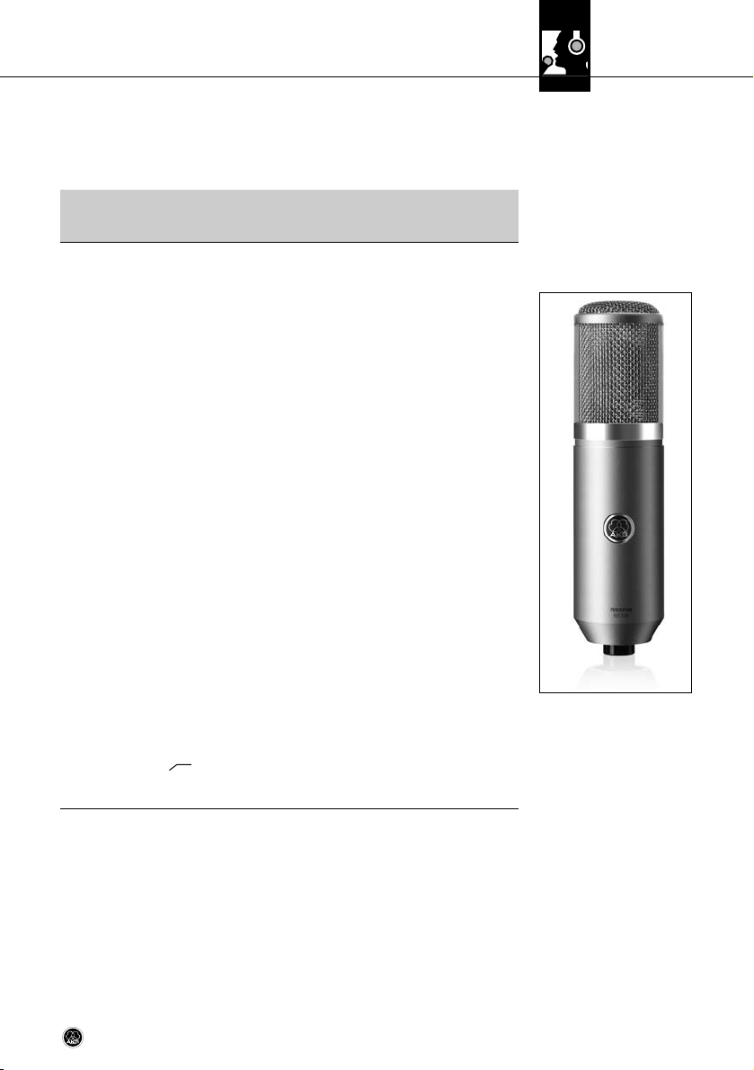
The PERCEPTION 820 TUBE is a high quality, true condenser microphone with a 1-inch dual
large-diaphragm transducer.
What sets it apart from other condenser microphones is that it uses a vacuum-tube preamplifier. Unlike conventional solid-state electronics, a tube preamplifier adds even-order harmonics to the signal. Although these are low in level, they create a rich, warm,
three-dimensional sound. This characteristic in conjunction with the typical response of the
large-diaphragm transducer will give your recordings a degree of warmth and “musicality”
that is difficult to achieve with solid-state microphones.
The microphone incorporates a carefully selected ECC 83 tube. If the tube needs replacing,
you may alternatively use a 12AX7 tube. This type is similar to the ECC 83.
Other features of the PERCEPTION 820 TUBE include:
• Selectable polar patterns: The microphone’s transducer uses a dual diaphragm. This
sophisticated technology allows you to select the optimum polar pattern (cardioid, omnidirectional, figure eight, and six intermediate patterns) for every application.
• Gold-sputtered diaphragm: The diaphragm is made of a plastic foil that is gold-sputtered on one side only to prevent shorting to the back electrode even at extremely high
sound pressure levels.
• All-metal body: The all-metal body adds to the rejection of RF interference so you can
use the microphone near transmitter stations and along with wireless microphones or
other communications equipment. The extremely rugged, heavy body and sturdy front
grill protect the microphone from damage from tough handling on stage.
• High headroom: Capable of handling sound pressure levels up to 155 dB and built to
resist high temperatures and humidity, the microphone will give excellent results in a wide
range of applications.
2.5 Remote Control Unit
4 PERCEPTION 820 TUBE
The Remote Control Unit delivered with your microphone
• provides the filament and plate voltages for the vacuum tube,
• supplies the polarization voltage for the transducer,
• lets you select one of nine different polar patterns,
• provides a 20-dB preattenuation pad, and
• allows you to switch in a bass cut filter.
Page 5
2 Description
BCD
A
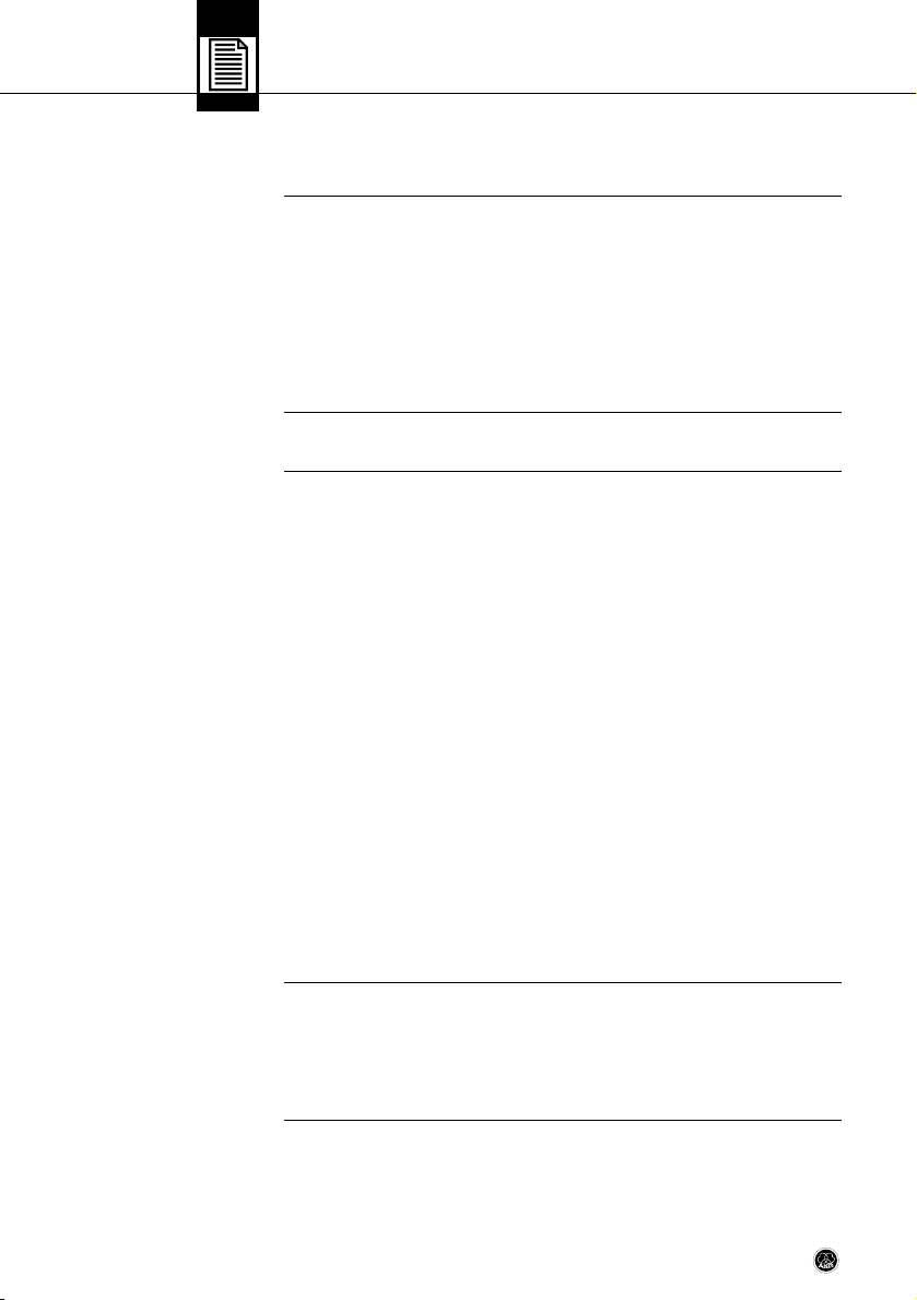
2.5.1 Front Panel
Fig. 1: Controls on the
Remote Control Unit
front panel.
A POWER LED: This blue LED is lit to indicate that power to the Remote Control Unit is ON.
B Polar pattern selector: This rotary switch lets you select the microphone’s polar pat-
tern from omnidirectional (fully CCW) to cardioid (center) to figure eight (fully CW). Between these settings, there are six intermediate patterns. All switch positions are
detented, so all settings are easily and unambiguously reproducible.
C Preattenuation switch: This toggle switch lets you increase the microphone’s headroom
by 20 dB for close-in recording with extremely low distortion. The preattenuation pad prevents the microphone's output level, particularly at low frequencies, from overloading the
miniature transformers used in many mixer input stages, etc.
D Bass cut switch: This toggle switch lets you reduce low-end distortion caused by foot-
fall or wind noise, etc. The bass cut filter also minimizes the proximity effect that closein miking from less than 4 inches causes in any unidirectional microphone. The filter
rolls off at 12 dB/octave from 80 Hz downward.
E
E POWER switch: Turns power to the unit ON (position “I”) and OFF (position “0”). The front
panel POWER LED is lit while power is ON and goes out when you turn power to the unit
OFF.
F AC input: Standard IEC power receptacle with integrated fuse holder.
• To avoid damage, use replacement fuses of the same type and rating (125 mA/
250 V, slow-blow) only.
G Power voltage selector: Sets the input power voltage to 210 - 240 VAC (“210-240V”
position) or 110 - 120 VAC (“110-120V” position).
F
G
H I
J
Refer to fig. 1.
2.5.2 Rear Panel
Fig. 2: Controls, inputs, and
outputs on the Remote
Control Unit rear panel.
Refer to fig. 2.
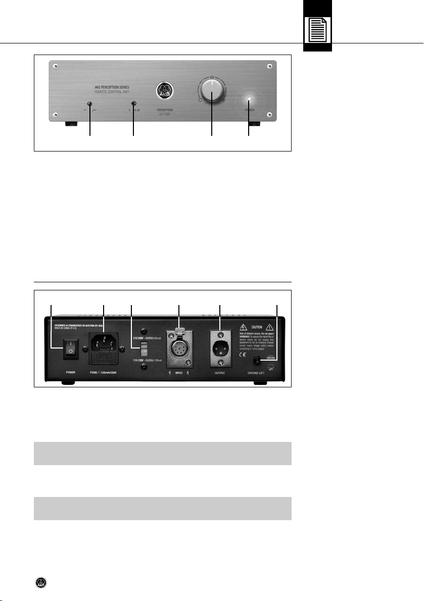
Important!
!
L
• To avoid damage, always make sure that the power voltage selector is set to the
same voltage as the power voltage available where you are going to use the unit.
H INPUT: 7-pin female XLR connector for connecting the dedicated audio/control cable
for the microphone.
I OUTPUT: This balanced 3-pin XLR connector provides the microphone output signal.
!
L
Important!
5PERCEPTION 820 TUBE
Page 6

2 Description
Refer to fig. 2 on page 5.
J GROUND LIFT: This pushbutton switch allows you to remove hum caused by ground
loops.
To open the chassis ground connection, press the GROUND LIFT button OUT (“LIFT” position).
To restore the chassis ground connection, press the GROUND LIFT button IN (“GROUND”
position).
6 PERCEPTION 820 TUBE
Page 7
3 Setting Up
• To avoid damage or electric shock, mount the microphone on a suitable stand
and make all audio connections before connecting the Remote Control Unit to
power.
D
B
A
C
1. Use the supplied audio/control cable (A) to connect the microphone output to the INPUT
connector(B) on the Remote Control Unit rear panel.
2. Use a standard balanced XLR cable (C) (optional) to connect the OUTPUT connector (D)
on the Remote Control Unit rear panel to the desired microphone input on your mixer.
1. Prior to connecting the Remote Control Unit to power, check what power voltage is available where you are going to use the microphone.
2. Set the power voltage selector (G) on the rear panel to the correct position as shown in
Table 1 below.
3.1 Important Note
!
L
3.2 Connecting
the Microphone
Fig. 3: Connecting the microphone to the Remote Control
Unit and mixer.
Refer to fig. 3.
3.3 Connecting
the Remote Control Unit
to Power
Refer to fig. 2 on page 5.
Power voltage Selector setting Power cord
210 to 240 VAC, 50/60 Hz 210-240V UK or European type
110 to 120 VAC, 50/60 Hz 110-120V US type
3. Referring to Table 1 above, use the correct power cord to connect the Remote Control
Unit to a grounded power outlet.
When on tour, you may encounter power outlets that do not match the power plug on
any of the supplied power cords.
• Purchase a suitable power cord locally that complies with IEC and local safety
standards and has a power plug with a chassis ground pin.
• To avoid damage or electric shock, connect the Remote Control Unit to a grounded
power outlet only.
• If in doubt about the power connection, consult a local electrician.
• Set the power switch on the Remote Control Unit rear panel to “I”.
After about ten seconds, the heating voltage will have reached the specified level and
the front panel POWER LED will be lit. About twenty seconds later, the microphone will
be ready to operate.
• You may not get the full splendor of the tube sound before the electrodes have reached
the required operating temperature. Therefore, we recommend powering up at least
Table 1: Power voltage vs. selector setting and power cord
Important!
!
L
3.4 Powering Up
Note:
7PERCEPTION 820 TUBE
Page 8

3 Setting Up
five minutes before starting to record. This will allow the tube inside the microphone
to heat up properly,
3.5 Powering Down
1. Set the power switch on the Remote Control Unit rear panel to “0”.
The front panel POWER LED will go out.
2. Wait for five minutes to allow the tube to cool down to room temperature before moving the microphone. A hot tube will be more susceptible to mechanical damage than a
cold one.
8 PERCEPTION 820 TUBE
Page 9
4 Using the Microphone
Using vacuum-tube electronics and a large-diaphragm transducer, the PERCEPTION 820
TUBE is suited for a wide range of applications. It will add the typical warmth and richness
tube microphones are famous for to female and male voices as well as many instruments.
The following sections contain general hints on using the microphone and suggestions on
how to place the microphone for voices and various instruments.
• Please remember that vacuum tubes with their heater filaments are more delicate than
solid-state components. Even a drop from moderate height may cause the filament to
break and the microphone to fail. So always handle the microphone with extreme care.
• Refer to fig. 4. Whichever polar pattern you select, it may be good to know which way
the transducer axis is facing: the front of the microphone is the side of the body with the
AKG logo on it.
• When recording wind instruments or vocals, make sure not to blow or sing directly into
the microphone.
To get professional sounding results with no unwanted wind and pop noise (exaggerated
“p” and “t” sounds), place an optional PF 80 pop screen from AKG between the microphone and vocalist/instrument.
• Keep the microphone dry. Moisture from blowing or singing directly at the capsule from
a short distance, or extremely high humidity may cause the microphone to start crackling or go very quiet due to partial short circuits in the polarization voltage.
• If you use the microphone in the open, use an optional AKG W 4000 windscreen to protect the microphone from moisture and reduce wind noise.
• Loud instruments: You can use this microphone for close-in recording of very loud instruments (brass instruments, kick drum, etc.). Just switch the preattenuation pad in to
increase the microphone’s capability of handling sound pressure levels to 155 dB.
- To switch the preattenuation pad in, set the preattenuation switch on the Remote
Control Unit front panel to “-20 dB”.
- To switch the preattenuation pad out of circuit, set the preattenuation switch to “0”.
4.1 Introduction
Note:
4.2 General Hints
• Low-frequency noise: The supplied spider type shock mount reduces footfall or other mechanical noise to a minimum.
The switchable bass cut filter at 80 Hz will effectively suppress any remaining low-frequency noise such as fan noise from air conditioning systems, etc., or floor vibrations,
handling noise, etc. without affecting the sound of the recorded voice or instrument on
tape.
- To switch the filter in, set the bass cut filter switch on the Remote Control Unit front
panel to the “ “ position.
- To switch the filter out of circuit, set the bass cut filter switch on the Remote Con-
trol Unit front panel to the “—“ position.
Fig. 4: Microphone front.
9PERCEPTION 820 TUBE
Page 10
4 Using the Microphone
4.3 Selecting
Polar Patterns
4.4 Hints on Microphone
Placement
4.4.1 Lead Vocals
Each of the PERCEPTION 820 TUBE’s selectable polar patterns is virtually frequency independent so that reflected sound, too will be reproduced accurately and uncolored.
• Omnidirectional (left-hand setting): This is the preferred setting for “all around the
mic” recording, high quality ambience (audience sound) miking, or far-field recording in
exceptionally good-sounding large or small recording rooms, etc.
• Cardioid (center setting): This is a standard setting for recording and gives excellent
results on all kinds of voices and a wide range of instruments. Remember to aim the microphone front (see fig. 4 on page 8) at the sound source.
• Figure eight (right-hand setting): The microphone will pick up sounds arriving from the
front and rear with equal sensitivity. Use this mode to mic up the side signal in M/S
stereo recording or to record two sound sources (talkers, instruments) facing each other.
It is also a good choice for cymbal overhead miking.
Every instrument radiates its sound in a specific way. Therefore, to get the best sound, do
not hesitate to experiment with microphone placement.
As an introduction to the “secret science of making good recordings”, the following sections
describe some proven miking techniques. (Illustrations show generic microphones.)
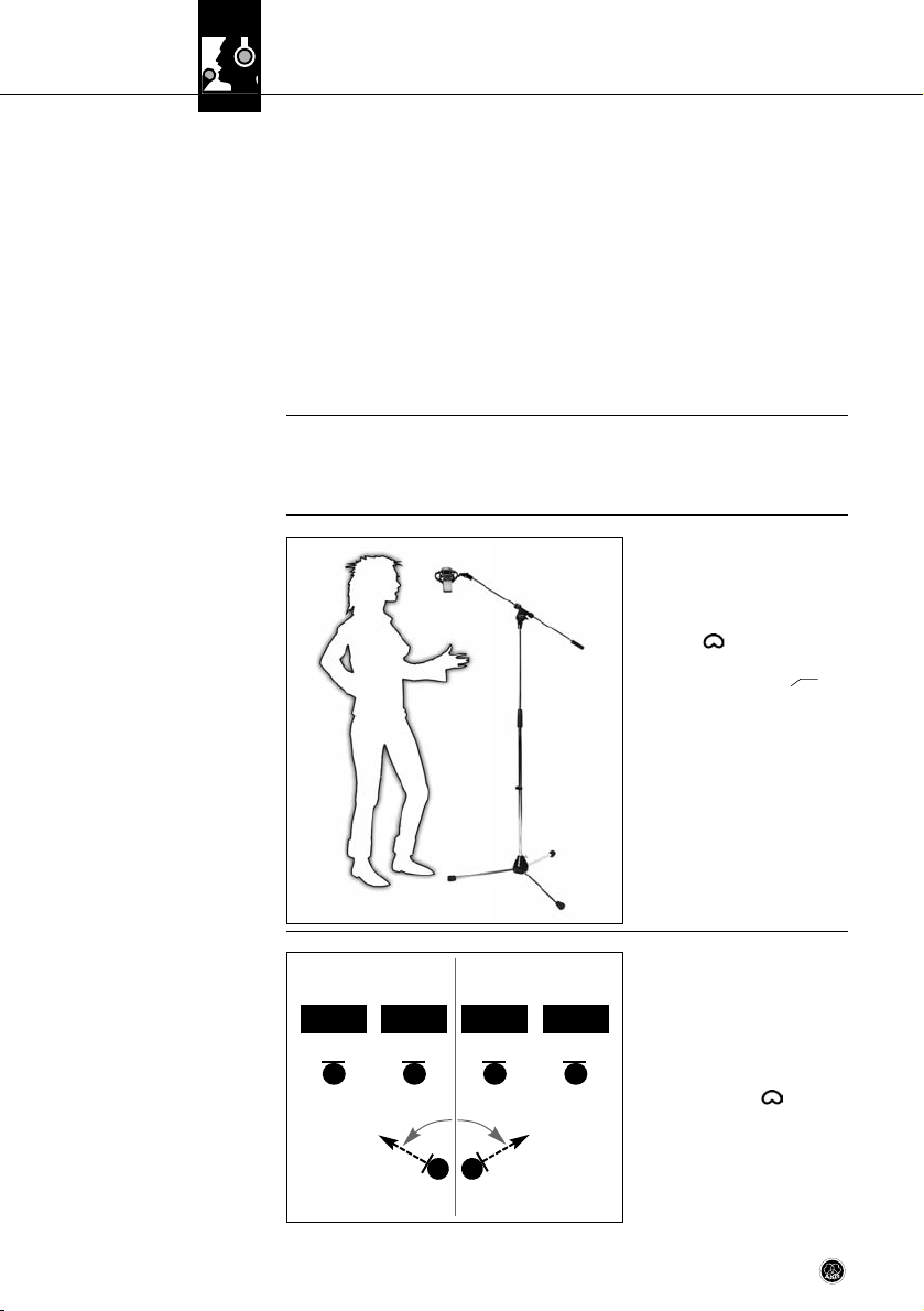
• Place the microphone 6 to 12 in.
(15 to 30 cm) from the vocalist’s
mouth.
• Select the cardioid polar pattern:
set the polar pattern selector to
cardioid ( ).
• Switch the bass cut filter in: set
the bass cut switch to “ ”.
• We strongly recommend placing
a PF 80 pop screen (available as
an optional accessory) between
the microphone and vocalist to
eliminate pop noise.
• To give the vocalist better control
of their own voice, we recommend adding the vocalist's track
to their headphone monitor signal.
Fig. 5: Solo vocalist.
4.4.2 Choir/
Backing Vocals
B T A S
P 820
Fig. 6: Miking a large
mixed choir.
10 PERCEPTION 820 TUBE
P 820 P 820 P 820
60°60°
• To record large mixed choirs, we
recommend using a pair of cardioid microphones to get a stereo
signal, plus one PERCEPTION 820
TUBE each for the soprano, alto,
tenor, and bass sections.
- Set each PERCEPTION 820
TUBE to cardioid ( ).
- Place each microphone about
5 feet (1.5 m) in front of the respective section, about 6 feet
(1.8 m) above the ground.
- Aim each microphone at the
center of its assigned section.
Page 11
4 Using the Microphone
• In rooms with good acoustics,
a pair of PERCEPTION 820
TUBEs will often do the trick.
- Set each microphone to
cardioid ( ).
- Use an optional H 50 stereo
bar to mount the two microphones on a stand.
• Place the stereo pair about
10 feet (3 m) in front of the
choir, about 8 feet (2.4 m)
above the ground.
- Aim the stereo pair at the
center of the choir.
- Turn the left-hand micro-
phone 60 degrees to the left and the right-hand microphone 60 degrees to the right.
Backing vocals/technique 1:
Refer to section 4.4.1 Lead Vocals above.
• If you have enough tracks available, we recommend overdubbing each voice separately.
Backing vocals/technique 2:
• If you use a separate microphone for each of several vocalists simultaneously, set each
microphone to hypercardioid (a
position between and )
to prevent crosstalk, particularly
if you place the microphones
close to one another.
B T A S
60°60°
H 50
Fig. 7: Using a stereo pair to
record a choir.
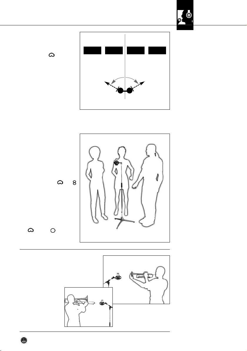
Backing vocals/technique 3:
• Refer to fig. 8. If you use a single microphone for the entire
group, select the cardioid
( ) or omni ( ) pattern and
place the vocalists in a semicircle in front of the microphone.
• Place the microphone about 1 foot (30 cm) in
front of the instrument, slightly off the bell
axis.
• Switch the preattenuation pad in.
• To reduce blowing noise, a PF 80 pop screen
(available as an optional accessory) between
the microphone and
instrument.
Fig. 8: Backing vocalists
sharing a single microphone.
4.4.3 Trumpet, Trombone
a
b
Fig. 9: Trumpet (a),
trombone (b).
11PERCEPTION 820 TUBE
Page 12
4 Using the Microphone
4.4.4 Electric Guitar/Bass
Fig. 10: Electric guitar.
4.4.5 Violin, Viola
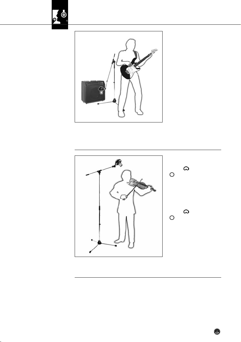
Electric guitar:
• Position the microphone 1 to
6 inches (2.5 to 15 cm) in front
of the speaker, aiming at a point
just off the speaker diaphragm
center.
• Use the bass cut and preattenuation pad.
• You may want to use an additional distant microphone to capture the sound of the speaker
cabinet as it interacts with the
room.
Electric bass:
• Use the same technique as for the electric guitar.
• You can use a DI box to add the direct signal of the line output on the bass amp to the
microphone signal.
Solo violin:
• Set the polar pattern selector to
cardioid ( ) or omnidirectional
().
• Direct the microphone at the f
holes from a height of 6 to 8 feet
(1.8 to 2.5 m) above the floor.
Viola:
• Set the polar pattern selector to
cardioid ( ) or omnidirectional
().
• Direct the microphone to the f
holes from a height of 7 to
10 feet (2.2 to 3 m) above the
floor.
Fig. 11: Violin.
Large string sections:
• Use a combination of a main microphone in an XY, MS, ORTF, or other stereo configuration and close-in spot microphones.
12 PERCEPTION 820 TUBE
Page 13

4 Using the Microphone
Double bass:
• Align the microphone with one
of the f holes from a distance of
about 16 inches (40 cm).
• If you need to record the double
bass together with an ensemble, place the microphone
closer to the instrument and set
the polar pattern to hypercardioid (turn the polar pattern selector one notch CW from
cardioid ( )) to prevent leakage from other instruments into
the bass microphone.
Cello/technique 1:
• Refer to “Double bass” above.
Cello/technique 2:
• Use a close-in microphone as
in technique 1 above plus a distant microphone.
• Set the level of the close-in microphone approx. 20 dB lower than the distant mic level.
We recommend using two microphones:
• Place one PERCEPTION 820
TUBE 8 to 12 inches (20 to
30 cm) away from the guitar
and aim at the sound hole.
• Aim a small-diaphragm microphone (e.g., a C 451B) at a
point near the bridge from a
distance of about 3 1/2 feet
(1 m) or at the body from a
point below and to the rear of
the instrument.
4.4.6 Double Bass, Cello
Fig. 12: Double bass.
4.4.7 Acoustic Guitar
Fig. 13: Miking an acoustic
guitar with a single
microphone.
We recommend using two microphones:
• Place mic 1 above and to one
side of the player (to reduce
blowing noise) and align it with
the player's mouth
• Aim mic 2 at the instrument
from the side.
• Refer to fig. 14. If you prefer to
use a single microphone, place
the microphone about 7 to
8 1/2 feet (2 to 2.5 m) above
the floor and aim as mic 1
above.
4.4.8 Flute
Fig. 14: Miking the flute with
a single microphone.
13PERCEPTION 820 TUBE
Page 14

4 Using the Microphone
4.4.9 Clarinet
Fig. 15: Clarinet.
4.4.10 Tenor and
Soprano Saxophones
• Point the microphone at the lowest key.
• To minimize key noise, place the
microphone a little ways to the
side of the instrument.
• Aim the microphone at the mid-
a
dle of the instrument from a distance of about 2 to 3 1/2 feet
(50 cm to 1 m).
b
Fig. 16: Tenor saxophone (a),
soprano saxophone (b).
4.4.11 Grand and
Upright Pianos
Fig. 17: Grand piano.
14 PERCEPTION 820 TUBE
Grand piano:
• Aim a single PERCEPTION 820
TUBE or a stereo pair (see section
4.4.2 Choir) at the middle strings
from a height of 5 to 7 feet (1.5 to
2 m).
• For a rock/pop sound, place two
microhones roughly 8 to 16 in.
(20 to 40 cm) above the strings.
• Align mic 1 with the treble strings
and mic 2 with the bass strings,
both at a point about 6 inches
(15 cm) behind the dampers.
Page 15

Upright piano:
• Use the same technique as for
the grand.
• Open the lid and let the microphones “peek into the instrument” from above.
4 Using the Microphone
Fig. 18: upright piano.
Overhead miking:
Refer to fig. 19.
• Place two PERCEPTION 820
TUBEs about 31 inches to
4 feet (80 to 120 cm) above the
drummer's head.
• Set each microphone to cardioid ( ) or omnidirectional
( ) mode.
• Use little or no EQ! This technique will pick up the entire kit,
delivering a highly natural
sound.
Cymbals:
To record cymbals on a separate
track, consider this technique:
• Place the microphone about
20 inches above and halfway
between the crash and ride cymbals.
• Set the polar pattern selector to figure eight ( ).
• Be sure to place the microphone out of reach of the drumsticks! The impact of a
drumstick hitting the microphone may break the heater filament and silence the
microphone.
4.4.12 Drums
Fig. 19: Typical drum kit.
Important!
!
L
15PERCEPTION 820 TUBE
Page 16

5 Cleaning
Important!
6.1 Replacing Fuses
Warning!
Fig. 20: Opening the fuse
!
L
↯
L
compartment.
• To avoid electric shock, make sure to disconnect the Remote Control Unit from
power before cleaning the microphone or the Remote Control Unit.
1. Disconnect the power cord from the Remote control Unit.
2. To clean the surfaces of the microphone body and Remote Control Unit, use a soft cloth
moistened with water.
6 Troubleshooting
• Dangerous voltages may be present inside the Remote Control Unit. To avoid electric shock, injury, and fire, UNDER ALL CIRCUMSTANCES disconnect the power
cord from the Remote Control Unit before replacing a fuse.
• To avoid damage, replace blown fuses with new fuses of the same type and rating only.
The fuse protecting the primary circuit is located in the marked fuse compartment below the
AC input connector on the Remote Control Unit rear panel.
To replace the fuse,
1. Use a flat-blade screwdriver to open the fuse compartment lid.
2. Remove the blown fuse.
3. Insert a new fuse of the same type and rating (125 mA/250 V slow-blow).
4. Close the fuse compartment lid.
16 PERCEPTION 820 TUBE
Page 17

6.2 Solving Problems
Problem Possible Cause Remedy
6 Troubleshooting
No sound.
Distortion.
Crackling noises or low output.
1. Power to mixer and/or recording
device is off.
2. Channel or master fader on mixer
or recording device is at zero.
3. Microphone is not connected to
mixer or recording device.
4. Cable connectors are seated
loosely.
5. Audio cable or audio/control cable
is defective.
6. No supply voltage.
7. Vacuum tube inside microphone is
defective.
8. Fuse blown.
1. Channel gain control on mixer set
too high.
2. Microphone too close to sound
source.
3. Microphone sensitivity set too high.
• Partial short circuits due to excessive humidity.
1. Switch power to mixer and/or
recording device on.
2. Set channel or master fader on
mixer or recording device to desired level.
3. Connect microphone to mixer or
recording device.
4. Check cable connectors for secure
seat.
5. Check cables and replace damaged
cable(s).
6. Check POWER LED. Switch power
to Remote Control Unit on.
Check audio/control cable and replace if necessary.
7. Contact your nearest AKG Service
Center.
8. Check POWER LED. Refer to section 6.1 above or contact your
nearest AKG Service Center.
1. Turn gain control down CCW.
2. Move microphone further away
from sound source.
3. Switch preattenuation pad in.
• Place microphone in warm, dry
room and allow to dry.
17PERCEPTION 820 TUBE
Page 18

7 Specifications
7.1 Microphone
7.2 Remote Control Unit
Type: 1-inch dual-diaphragm, true condenser pressure-
gradient microphone
Polar patterns: omnidirectional, cardioid, figure eight plus six
intermediate patterns (selectable on Remote
Control Unit)
Open-circuit sensitivity
at 1kHz (cardioid): 20 mV/Pa (-34 dBV ±3 dB)
Frequency range: 20 Hz to 20 kHz (see frequency response graphs)
Impedance: ≤ 200 ohms
Recommended load impedance: ≥ 1000 ohms
Equivalent noise level
to IEC 60268-4 (A-weighted): 16 dB-A
Signal/noise ratio re 1 Pa (A-weighted): 78 dB
Max. SPL: 135 / 155 dB SPL (0 / -20 dB)
Preattenuation pad: -20 dB (switchable on Remote Control Unit)
Bass cut filter slope: 12 dB/octave, 80 Hz
(switchable on Remote Control Unit)
Environment: temperature: -10°C to +60°C
R.H.: 80% (+25°C)
Powering: via Remote Control Unit only
Connector: dedicated 7-pin male XLR
Dimensions: 53 dia. x 212 mm high / 2 x 8.3 in.
Net weight: 870 g / 1.9 lbs.
Audio/control input: dedicated 7-pin female XLR connector
Audio output: standard 3-pin male XLR connector,
balanced, pin 2 hot
Polar pattern selector: 9-position detented rotary switch
Bass cut filter switch: 2-position toggle switch
Preattenuation switch: 2-position toggle switch
Power voltage: 210-240 VAC or 110-120 VAC, selectable
Primary fuse: 125 mA / 250 V slow-blow
18 PERCEPTION 820 TUBE
Page 19

7 Specifications
Frequency Response Polar Diagram
Omni-
directional
Cardioid
Figure Eight
19PERCEPTION 820 TUBE
Page 20

Sommaire
Page
1 Sécurité et environnement ........................................................................................................21
1.1 Symboles utilisés.................................................................................................................21
1.2 Consignes de sécurité..........................................................................................................21
1.3 Environnement ....................................................................................................................21
2 Description ................................................................................................................................22
2.1 Introduction.........................................................................................................................22
2.2 Fournitures .........................................................................................................................22
2.3 Accessoires optionnels.........................................................................................................22
2.4 Microphone.........................................................................................................................22
2.5 Unité de commande à distance .............................................................................................22
2.5.1 Face avant .................................................................................................................23
2.5.2 Face arrière................................................................................................................23
3 Réglage .....................................................................................................................................25
3.1 Remarque importante ..........................................................................................................25
3.2 Raccordement du microphone ..............................................................................................25
3.3 Raccordement au secteur de l’unité de commande à distance .................................................25
3.4 Mise sous tension................................................................................................................25
3.5 Mise hors tension ................................................................................................................26
4 Utilisation du microphone..........................................................................................................27
4.1 Introduction.........................................................................................................................27
4.2 Conseils généraux ...............................................................................................................27
4.3 Sélection de la directivité ......................................................................................................28
4.4 Conseils de positionnement du microphone ...........................................................................28
4.4.1 Soliste vocal ...............................................................................................................28
4.4.2 Chorale/Choristes .......................................................................................................29
4.4.3 Trompette, trombone ...................................................................................................30
4.4.4 Guitare électrique/Guitare basse ..................................................................................30
4.4.5 Violon, alto..................................................................................................................30
4.4.6 Contrebasse, violoncelle..............................................................................................31
4.4.7 Guitare sèche .............................................................................................................31
4.4.8 Flûte traversière..........................................................................................................32
4.4.9 Clarinette ...................................................................................................................32
4.4.10 Saxophones ténor et soprano.....................................................................................32
4.4.11 Piano à queue/Piano droit..........................................................................................33
4.4.12 Batterie....................................................................................................................33
5 Nettoyage ..................................................................................................................................34
6 Dépannage ................................................................................................................................34
6.1 Remplacement du fusible .....................................................................................................34
6.2 Solutions aux problèmes ......................................................................................................35
7 Caractéristiques techniques......................................................................................................36
7.1 Microphone.........................................................................................................................36
7.2 Unité de commande à distance .............................................................................................36
Réponse en fréquence et directivité..............................................................................................37
Conformité ...................................................................................................................................38
20 PERCEPTION 820 TUBE
Page 21

1 Sécurité et environnement
Le symbole représentant un éclair avec une flèche à l’intérieur d’un triangle équilatéral est utilisé pour prévenir l’utilisateur de la présence de tensions électriques dange-
↯
L
reuses à l’intérieur de l’appareil.
Le symbole représentant un point d’exclamation à l’intérieur d’un triangle équilatéral,
tel qu’il figure sur l’appareil, indique qu’il est nécessaire pour l’utilisateur de consulter
!
L
le mode d’emploi. Celui-ci utilise ce symbole pour signaler des instructions que l’utilisateur doit suivre afin d’assurer un fonctionnement de l’appareil en toute sécurité.
1. Faites attention de ne pas renverser de liquides sur l’appareil et que rien ne tombe à l’intérieur par les fentes d’aération.
2. N’utilisez en aucun cas l’appareil dans un local humide. N’exposez pas l’appareil à des projections d’eau ou à la pluie. Ne posez jamais des objets contenant un liquide (p. ex. vases) sur
l’appareil ou à proximité de celui-ci.
3. Aucun élément à l’intérieur de l’appareil ne peut être entretenu par l’utilisateur. Par conséquent,
n’essayez pas de vous charger de son entretien. Confiez toutes les tâches d’entretien au personnel technique autorisé. L’ouverture du boîtier pour quelque raison que ce soit annulera la
garantie du fabricant.
4. Avant de raccorder l’appareil au secteur, vérifiez que la tension d’alimentation en courant alternatif indiquée sur le bloc d’alimentation fourni avec l’appareil est identique à la tension
secteur c.a. là où vous utiliserez l’appareil. Contrôlez que cet appareil soit branché sur une prise
secteur aux normes, avec protection par mise à la terre. L’interruption de la connexion à la terre
ou l’utilisation de fiches ou de prises secteur non conformes aux normes est interdite.
5. Utilisez l’appareil uniquement avec le bloc d’alimentation fourni avec celui-ci. Tout autre type
de courant ou de tension risquerait d’endommager sérieusement l’appareil.
6. S’il arrive qu’un objet quelconque ou du liquide pénètre à l’intérieur de l’appareil, mettez immédiatement la chaîne hors tension. Débranchez aussitôt l’appareil de la prise secteur et faites-le réviser par notre service après-vente.
7. Si vous avez l’intention de rester quelque temps sans utiliser l’appareil, débranchez-le. Tant
que l’appareil est branché sur la prise secteur, il n’est pas entièrement coupé du secteur
lorsque vous le mettez hors tension.
8. En cas d’orages, débranchez l’appareil de la prise secteur pour éviter tout dommage.
9. Veillez à faire cheminer les cordons secteur de manière à ce que personne n’y marche dessus ou qu’ils ne soient pas pincés par des objets placés sur ou contre eux, en accordant une
attention particulière aux cordons au niveau des fiches, des prises de courant et à l’endroit où
ils sortent de l’appareil.
10. Pour éviter les parasites et les interférences, faites passer tous les fils audio, en particulier ceux
raccordés aux entrées du micro, loin des lignes de secteur quelles qu’elles soient. Si vous
utilisez des conduits pour câbles, assurez-vous d’utiliser des conduits séparés pour les fils
audio.
11. Veillez à remplacer le fusible d’origine uniquement par un fusible aux normes, du même type
et du même calibre. La non-observation de cette règle peut entraîner un échauffement excessif
et/ou un risque d’incendie.
12. Ne placez jamais l’appareil à proximité d’une source de chaleur (radiateurs, tuyaux de chauffage, amplificateurs, etc.) ni à un endroit où il serait exposé directement au soleil, à une
atmosphère poussiéreuse, à l’humidité, à la pluie, à des vibrations mécaniques ou des secousses.
13. Pour nettoyer l’appareil, utilisez un chiffon légèrement humide mais jamais mouillé. N’oubliez
surtout pas de débrancher auparavant l’appareil du secteur ! N’utilisez jamais de produits de
nettoyage caustiques ou décapants, ni des produits contenant de l’alcool ou un solvant qui risqueraient d’abîmer l’émail et les éléments en plastique.
14. N’utilisez jamais l’appareil pour une application autre que celles indiquées dans ce mode
d’emploi. AKG décline toute responsabilité concernant des dommages qui résulteraient d’une
manipulation inappropriée ou d’une utilisation non conforme.
1. Si vous mettez l’appareil au rebut, enlevez le boîtier, les cartes de circuits et les câbles et débarrassez-vous de tous ces composants conformément aux règlementations locales en vigueur pour l’élimination des déchets.
2. L’emballage de l’appareil est recyclable. Jetez-le dans un container prévu à cet effet par la déchetterie/la société de recyclage locale et respectez la législation locale en matière d’élimination des déchets et de recyclage.
!
L
1.1 Symboles utilisés
1.2 Consignes de sécurité
1.3 Environnement
21PERCEPTION 820 TUBE
Page 22

2 Description
2.1 Introduction
2.2 Four nitures
2.3 Accessoires
optionnels
2.4 Microphone
Nous vous remercions d’avoir choisi un produit AKG. Ce mode d’emploi contient des instructions importantes pour le réglage et l’utilisation de votre appareil. Veuillez prendre
quelques minutes pour lire attentivement les instructions ci-dessous avant de mettre
l’appareil en service. Conservez le mode d’emploi pour pouvoir le consulter lorsque vous
aurez des questions. Nous vous souhaitons beaucoup de plaisir dans l’utilisation de l’appareil.
• Microphone PERCEPTION 820 TUBE
• Unité de commande à distance
• Câble de commande/audio
• Attache de type Spider
• Cordon secteur type US
• Cordon secteur type UK
• Cordon secteur type Europe
• Vérifiez que l’emballage contient bien toutes les pièces énumérées ci-dessus. Si ce n’est
pas le cas, contactez votre fournisseur AKG.
• Vous trouverez la liste des accessoires optionnels dans le catalogue/dépliant AKG actuel
ou sur www.akg.com. Votre fournisseur se tient également à votre disposition pour vous
conseiller.
Le PERCEPTION 820 TUBE est un microphone à condensateur de grande qualité avec un
transducteur à double membrane d’un diamètre de 2,5 cm.
Ce qui le distingue des autres microphones à condensateur est le fait qu’il utilise un préamplificateur à tube à vide. A la différence des dispositifs électroniques classiques à semiconducteurs, un préamplificateur à tubes ajoute des harmoniques d’ordre pair au signal.
Bien que ceux-ci soient faibles, ils créent un son tridimensionnel riche et chaud. Cette caractéristique associée à la réponse typique du transducteur à grande membrane donnera à
vos enregistrements un degré de chaleur et de « musicalité » difficile à obtenir avec des
microphones à semi-conducteurs.
Le microphone comprend un tube ECC 83 choisi avec soin. Lorsque cela est nécessaire, vous
pouvez remplacer celui-ci par un tube 12AX7 similaire au ECC 83.
Autres caractéristiques du PERCEPTION 820 TUBE :
• Directivité commutable via un sélecteur : le transducteur du microphone utilise une
double membrane. Cette technologie sophistiquée vous permet de sélectionner la directivité optimale (cardioïde, omnidirectionnelle, huit, et six caractéristiques intermédiaires) pour chaque application.
• Membrane pulvérisée à l’or : la membrane est constituée d’une feuille de matière
synthétique pulvérisée à l’or sur une face ce qui évite, même à des niveaux de pression
acoustique très élevés, d’éventuels courts-circuits avec la contre-électrode.
• Boîtier entièrement métallique : son boîtier tout en métal protège efficacement le
microphone contre les parasites de haute fréquence lorsqu’il est utilisé à proximité d'un
émetteur ou avec des microphones ou d’autres types de systèmes de communication
sans fil. Le boîtier massif et très résistant ainsi que la grille avant robuste protègent le
microphone contre des dommages pouvant découler d’une rude manipulation sur scène.
• Plage dynamique étendue : capable de gérer des niveaux de pression acoustique al-
lant jusqu’à 155 dB et construit pour résister à une humidité et à des températures élevées, le microphone fournit d’excellents résultats dans toute une série d’applications.
2.5 Unité de commande
à distance
22 PERCEPTION 820 TUBE
L’unité de commande à distance livrée avec le microphone
• alimente le transducteur en tension de polarisation
• vous permet de sélectionner une des neuf directivités différentes
• fournit une pré-atténuation de 20 dB et
• vous permet d’activer un filtre de réduction des basses.
Page 23

2 Description
BCD
A
2.5.1 Face avant
Fig. 1 : Commandes sur la
face avant de l’unité de
commande à distance
A LED POWER : cette LED bleue est éclairée lorsque l’unité de commande à distance est
SOUS TENSION.
B Sélecteur de directivité : ce bouton rond vous permet de sélectionner la directivité du
microphone – omnidirectionnelle (bouton tourné entièrement dans le sens inverse des
aiguilles d’une montre), cardioïde (bouton positionné au centre) ou huit (bouton tourné
entièrement dans le sens des aiguilles d’une montre). Outre ces réglages, il existe six
caractéristiques intermédiaires. Toutes les positions du bouton sont à crans si bien que
tous les réglages peuvent être reproduits facilement et sans ambiguïté.
C Commutateur de pré-atténuation : ce commutateur à bascule vous permet de ré-
duire la sensibilité du microphone de 20 dB afin de pouvoir réaliser des prises de son à
distorsion extrêmement réduite à proximité immédiate d’une source sonore. Cette préatténuation évite que le niveau de sortie du microphone, particulièrement dans les basses fréquences, dépasse le seuil critique de micro-transformateurs comme ceux qui
sont intégrés aux entrées des consoles de mixage.
D Commutateur du filtre de réduction des basses : ce commutateur à bascule vous
permet de réduire les distorsions qui pourraient affecter les basses fréquences à la suite
de bruits de vent ou de pop. Ce filtre de réduction des basses réduit donc aussi l’effet
de proximité qui peut se manifester avec un microphone unidirectionnel placé à faible
distance (moins de 10 cm) de la source sonore. La pente du filtre est de 12 dB/octave
à partir d’une fréquence descendante de 80 Hz.
E
F
G
H I
J
Voir fig. 1.
2.5.2 Face arrière
Fig. 2 : Commandes, entrées,
sorties sur la face arrière de
l’unité de commande
à distance
E Interrupteur POWER : il permet de mettre l’unité sous tension (position « 1 ») ou hors
tension (position « 0 »). La LED POWER sur la face avant est éclairée lorsque l’unité est
sous tension et s’éteint lorsque vous mettez l’unité hors tension.
F Entrée c.a. : prise de courant selon la norme IEC avec porte-fusible intégré.
• En cas de remplacement du fusible, utilisez uniquement un fusible du même type
et du même calibre que celui d’origine (125 mA/250 V, à action retardée) afin d’éviter d’endommager l’appareil.
G Sélecteur de tension : il sert à régler la tension d’entrée à une valeur comprise entre 210
et 240 V c.a. (position « 210-240V ») ou 110 et 120 V c.a. (position « 110-120V »).
Voir fig. 2.
!
L
Important !
23PERCEPTION 820 TUBE
Page 24

2 Description
Important !
Voir fig. 2, page 23.
!
L
• Pour éviter des dommages, assurez-vous systématiquement que le sélecteur de
tension soit réglé sur la même tension que la tension secteur disponible sur le
lieu d’utilisation de l’appareil.
H INPUT : connecteur XLR femelle 7 broches pour le raccordement du câble de com-
mande/audio dédié du microphone.
I OUTPUT : ce connecteur équilibré XLR 3 broches sert à la sortie du signal du micro-
phone.
J GROUND LIFT : cet interrupteur à poussoir vous permet de supprimer le ronflement
provoqué par une boucle de masse.
Pour couper la connexion du boîtier à la terre, appuyez sur le bouton GROUND LIFT pour
le mettre en position « LIFT ».
Pour rétablir la connexion du boîtier à la terre, appuyez sur le bouton GROUND LIFT pour
le mettre en position « GROUND ».
24 PERCEPTION 820 TUBE
Page 25

3 Réglage
• Pour éviter tout dommage ou décharge électrique, montez le microphone sur un
pied adéquat et procédez à toutes les connexions audio avant de raccorder au
secteur l’unité de commande à distance.
D
B
A
C
1. Utilisez le câble de commande/audio (A) fourni avec l’appareil pour raccorder la sortie
du microphone au connecteur INPUT (B) sur la face arrière de l’unité de commande à
distance.
2. Utilisez un câble XLR équilibré standard (C) (en option) pour raccorder le connecteur
INPUT (D) sur la face arrière de l’unité de commande à distance à l’entrée de microphone
souhaitée sur votre console de mixage.
1. Avant de raccorder au secteur l’unité de commande à distance, vérifiez quelle tension
secteur est disponible sur le lieu d’utilisation du microphone.
2. Réglez le sélecteur de tension (G), situé sur la face arrière, sur la position qui convient,
conformément au tableau 1 ci-dessous.
3.1 Remarque
importante
!
L
3.2 Raccordement
du microphone
Fig. 3 : Raccordement du
microphone à l’unité de
commande à distance et
à la console de mixage
Voir fig. 3.
3.3 Raccordement au
secteur de l’unité de
commande à distance
Voir fig. 2, page 23.
Tension secteur Réglage du sélecteur Cordon secteur
210 à 240 V c.a., 50/60 Hz 210-140V type UK ou Europe
110 à 120 V c.a., 50/60 Hz 110-120V type US
3. Conformément au tableau 1 ci-dessus, utilisez le cordon secteur qui convient pour raccorder l’unité de commande à distance à la prise de courant mise à la terre.
Lorsque vous êtes en tournée, il se peut que vous rencontriez des prises de courant
qui ne correspondent pas aux fiches des cordons secteur fournis avec l’appareil.
• Achetez, sur place, un cordon secteur adéquat conforme aux normes IEC et de sécurité dans le pays en question et ayant une fiche secteur avec une broche terre.
• Pour éviter tout dommage ou décharge électrique, raccordez l’unité de commande à distance uniquement à une prise secteur avec une broche de terre.
• En cas de doute concernant le raccordement au secteur, consultez un électricien
sur place.
• Mettez sur la position « 1 » l’interrupteur POWER situé sur la face arrière de l’unité de
commande à distance.
Après 10 secondes environ, la tension de chauffage aura atteint le niveau requis et la
LED POWER sur la face avant s’éclairera. Environ 20 secondes plus tard, le microphone
sera prêt à fonctionner.
Tab. 1 : Tension de secteur,
réglage du sélecteur et
cordon secteur
Important !
!
L
3.4 Mise sous tension
25PERCEPTION 820 TUBE
Page 26

3 Réglage
Note :
3.5 Mise hors tension
• Vous n’obtiendrez pas toute la splendeur d’un son « dit de tube » avant que les électrodes aient atteint la température de fonctionnement requise. Nous recommandons donc
de mettre le microphone sous tension au moins 5 minutes avant de commencer
la prise de son. Cela permet au tube à l’intérieur du microphone de chauffer correctement.
1. Mettez sur la position « 0 » l’interrupteur POWER situé sur la face arrière de l’unité de
commande à distance.
La LED POWER sur la face avant s’éteindra.
2. Attendez cinq minutes pour permettre au tube de refroidir avant d’enlever le microphone. Un tube chaud sera plus sensible aux chocs mécaniques qu’un tube froid.
26 PERCEPTION 820 TUBE
Page 27

4 Utilisation du microphone
Utilisant un tube à vide et un transducteur à grande membrane, le PERCEPTION 820 TUBE
convient pour toute une série d’applications. Il ajoutera à des voix féminines et masculines
ainsi qu’à de nombreux instruments la chaleur et la richesse typiques qui font la réputation
des microphones à tubes. Les sections suivantes contiennent des conseils généraux sur l’utilisation du microphone et des suggestions sur la façon de le positionner pour les voix et différents instruments.
• Souvenez-vous que les tubes à vide avec leurs filaments incandescents sont plus délicats que les composants à semi-conducteurs. Une chute même modérée du microphone peut provoquer la rupture du filament et donc la panne. Manipulez par conséquent
le microphone avec très grand soin.
• Voir fig. 4. Quelle que soit la directivité que vous sélectionniez, il peut être utile de savoir comment est orienté l’axe du transducteur : la face avant du microphone correspond
au côté sur lequel figure le logo AGK.
• Lors de la prise de son d’instruments à vent ou de voix, veillez à ne pas souffler ou chanter directement dans le microphone.
Pour obtenir des sons professionnels sans bruits de vent ou de pop (sons « p » et « t »
exagérés), placez un filtre anti-pop PF 80 d’AKG (en option) entre le microphone et le
chanteur/la chanteuse.
• Veillez à ce que le microphone reste sec. L’humidité causée en soufflant ou en chantant
près de la capsule ou une très grande humidité extérieure peuvent provoquer un début
de grésillement du microphone ou une nette baisse de volume en raison de courts-circuits partiels dans la tension de polarisation.
• Si vous utilisez le microphone à l’air libre, utilisez une bonnette anti-vent W 4000 d’AKG
(en option) pour protéger le microphone contre l’humidité et réduire les bruits de vent.
• Instruments à haut volume sonore : vous pouvez utiliser ce microphone pour enregistrer de près des instruments à très grande densité sonore (cuivres, grosse caisse, etc.).
Activez simplement la pré-atténuation pour augmenter la capacité du microphone à
gérer des niveaux de pression acoustique allant jusqu’à 155 dB.
- Pour activer la pré-atténuation, réglez sur « -20 dB » le commutateur de pré-atté-
nuation situé sur la face avant de l’unité de commande à distance.
- Pour désactiver la pré-atténuation, réglez sur « 0 » le commutateur de pré-atté-
nuation.
4.1 Introduction
Note :
4.2 Conseils généraux
• Bruits à basse fréquence : l’attache de type Spider fournie avec le microphone réduit au
minimum les vibrations de basses fréquences dues aux mouvements de plancher ou autres bruits mécaniques.
Le filtre de réduction des basses commutable de 80 Hz vous permet de faire disparaître efficacement tous les bruits à basse fréquence tels que la soufflerie de climatisations
ou les vibrations dues aux mouvements de plancher, les bruits de manipulation, etc.
sans pour autant modifier les caractéristiques sonores des instruments ou des voix enregistrés.
- Pour activer le filtre, mettez sur la position « » le commutateur de réduction des
basses situé sur la face avant de l’unité de commande à distance.
- Pour désactiver le filtre, mettez sur la position « — » le commutateur de réduction
des basses situé sur la face avant de l’unité de commande à distance.
Fig. 4 : Face avant
du microphone
27PERCEPTION 820 TUBE
Page 28

4 Utilisation du microphone
4.3 Sélection
de la directivité
4.4 Conseils de
positionnement
du microphone
4.4.1 Soliste vocal
Fig. 5 : Soliste
Chaque directivité pouvant être sélectionnée sur le microphone PERCEPTION 820 TUBE est
virtuellement indépendante de la fréquence si bien que les sons renvoyés sont eux aussi reproduits avec précision et sans être faussés.
• Omnidirectionnelle (sélecteur à gauche) : c’est le réglage privilégié pour l’enregis-
trement de l’environnement « tout autour du micro », pour une prise de son d’ambiance
de haute qualité (son du public) ou pour un enregistrement à grande distance dans des
salles d’enregistrement, petites ou grandes, ayant une acoustique exceptionnelle, etc.
• Cardioïde (sélecteur au centre) : il s’agit du réglage standard d’enregistrement qui
donne d’excellents résultats pour tous les types de voix et une vaste gamme d’instruments. Veillez à bien orienter la face avant du microphone vers la source sonore (voir
fig. 4, page 8).
• Huit (sélecteur à droite) : le microphone captera avec la même sensibilité les sons
venant de l’avant et de l’arrière. Utilisez ce mode pour la prise du signal latéral en enregistrement stéréo M/S ou pour enregistrer deux sources sonores (paroles, instruments)
situées en face l’une de l’autre. Ce réglage est également intéressant pour la prise de
son « overhead » de cymbales.
Chaque instrument émet des sons d’une manière qui lui est propre. Par conséquent, pour
obtenir le meilleur son, n’hésitez pas à faire des essais en positionnant le microphone à différents endroits.
En guise d’introduction aux techniques de l’enregistrement, vous trouverez ci-dessous l’essentiel des règles de positionnement de microphones (les illustrations montrent des microphones génériques).
• Placez le microphone à une distance de 15 à 30 cm de la bouche du/de la soliste.
• Sélectionnez la directivité cardioïde : réglez pour cela le sélecteur de directivité sur cardioïde
().
• Activez le filtre de réduction des
basses en mettant le commutateur correspondant sur la position « ».
• Nous recommandons vivement
de placer un filtre anti-pop PF 80
(disponible comme accessoire
optionnel) entre le microphone et
le/la soliste pour éliminer les
bruit de pop.
• Pour permettre au/à la soliste un
meilleur contrôle de sa voix, nous
recommandons d’ajouter sa
piste au mélange destinée à son
retour de casque.
28 PERCEPTION 820 TUBE
Page 29

4 Utilisation du microphone
• Dans le cas de grandes chorales mixtes, nous recomman-
dons d’utiliser deux
microphones cardioïdes, pour
obtenir un son stéréo, ainsi
qu’un microphone PERCEPTION 820 TUBE pour chaque
voix : sopranos, altos, ténors et
basses.
- Sélectionnez la directivité
cardioïde ( ) pour chaque
PERCEPTION 820 TUBE.
- Positionnez chaque micro-
phone à environ 1,5 m devant le groupe de voix respectif et à une hauteur d’environ 1,8 m au-dessus du sol.
- Placez chaque microphone au centre de son groupe de voix.
• Dans les salles où l’acous-
tique est optimale, deux
microphones PERCEPTION 820
TUBE sont souvent suffisants.
- Sélectionnez la directivité
cardioïde ( ) pour chaque
microphone.
- Utilisez une barrette stéréo
H 50 en option pour monter
les deux microphones sur
un pied.
• Placez le couple stéréo à environ 3 m devant la chorale et à
une hauteur d’environ 2,4 m
au-dessus du sol.
- Dirigez le couple stéréo vers le centre de la chorale.
- Tournez le microphone de gauche de 60 degrés vers la gauche et celui de droite de
60 degrés vers la droite.
B T A S
P 820
P 820 P 820 P 820
60°60°
B T A S
60°60°
H 50
4.4.2 Chorale/Choristes
Fig. 6 : Prise de son d’une
grande chorale mixte
Fig. 7 : Utilisation d'un couple
stéréo pour la prise de son
d’une chorale
Choristes/variante 1 :
Voir ci-dessus la section 4.4.1 Soliste vocal.
• Si le nombre de pistes est suffisant, nous recommandons d’enregistrer les voix l’une
après l’autre.
Choristes/variante 2 :
• Lors de l’enregistrement simultané de
plusieurs voix disposant chacune d’un
microphone, sélectionnez la directivité
hypercardioïde (une position entre
et ) pour éviter la diaphonie, surtout si
les microphones sont très rapprochés.
Choristes/variante 3 :
• Voir fig. 8. Si vous utilisez un seul microphone pour tout le groupe, sélectionnez la directivité cardioïde ( ) ou
omnidirectionnelle ( ) et placez les
choristes en demi-cercle autour du
microphone.
Fig. 8 : Choristes avec
un seul microphone
29PERCEPTION 820 TUBE
Page 30

4 Utilisation du microphone
4.4.3 Trompette,
trombone
Fig. 9 : Trompette (a),
trombone (b)
4.4.4 Guitare élec-
trique/Guitare basse
Fig. 10 : Guitare électrique
a b
• Placez le microphone devant l’instrument, à environ 30 cm et hors de l’axe du pavillon.
• Activez la pré-atténuation.
• Pour réduire les bruits de souffle, placez un filtre anti-pop PF 80 (disponible comme accessoire optionnel) entre le microphone et l’instrument.
Guitare électrique :
• Placez le microphone à une distance de 2,5 à 15 cm de la
membrane du haut-parleur, légèrement décalé par rapport au
centre de celle-ci.
• Activez le filtre de réduction des
basses et la pré-atténuation.
• Prévoyez éventuellement un
deuxième microphone d’ambiance pour capturer le son du
haut-parleur lors de son interaction avec la pièce.
Guitare basse :
• Procédez comme pour la guitare
électrique.
• Vous pouvez ajouter au mixage
le signal direct, en passant par une boîte de direct (DI-Box) en utilisant la sortie LINE OUT
de l’amplificateur.
4.4.5 Violon, alto
Fig. 11 : Violon
30 PERCEPTION 820 TUBE
Violon solo :
• Réglez le sélecteur de directivité
sur cardioïde ( ) ou omnidirectionnelle ( ).
• Dirigez le microphone vers les
ouïes f, à une hauteur de 1,8 m
à 2,5 m au-dessus du sol.
Alto :
• Réglez le sélecteur de directivité
sur cardioïde ( ) ou omnidirectionnelle ( ).
• Dirigez le microphone vers les
ouïes f, à une hauteur de 2,2 m
à 3 m au-dessus du sol.
Page 31

4 Utilisation du microphone
Grands ensembles à cordes :
• Utilisez un couple stéréo en configuration XY, MS, ORTF ou autre, combiné à des microphones d’appoint à proximité des instruments.
Contrebasse :
• Placez le microphone à environ
40 cm de l’une des ouïes f.
• Si la contrebasse doit être enregistrée au sein d’un ensemble instrumental, rapprochez le
microphone de l’instrument et
sélectionnez la directivité hypercardioïde (en tournant le sélecteur de directivité d’un cran
dans le sens des aiguilles d’une
montre à partir de la position
cardioïde ( ), pour éviter que
d’autres instruments n’interfèrent sur le microphone de la
contrebasse.
Violoncelle/variante 1 :
• Voir ci-dessus la section
« Contrebasse ».
Violoncelle/variante 2 :
• Utilisez un microphone de proximité comme dans la variante 1 ci-dessus, ainsi qu’un
microphone d’ambiance.
• Réglez le niveau du microphone de proximité environ 20 dB plus bas que celui du microphone d’ambiance.
Nous recommandons l’utilisation de
deux microphones.
• Placez, à une distance de 20 à
30 cm de la guitare, un microphone PERCEPTION 820 TUBE
dirigé vers la rosace.
• Placez en outre, à une distance
d’environ 1 mètre, un microphone à petite membrane
(comme par exemple un
C 451B), dirigé vers le chevalet
ou vers l’arrière de la caisse.
4.4.6 Contrebasse,
violoncelle
Fig. 12 : Contrebasse
4.4.7 Guitare sèche
Fig. 13 : Prise de son d’une
guitare sèche au moyen d’un
seul microphone
31PERCEPTION 820 TUBE
Page 32

4 Utilisation du microphone
4.4.8 Flûte traversière
Fig 14 : Prise de son d’une
flûte traversière au moyen
d’un seul microphone
4.4.9 Clarinette
Nous recommandons l’utilisation de
deux microphones.
• Placez le microphone 1 au-dessus de la bouche de l’instrumentiste (pour éviter les bruits de
souffle) et dirigé vers celle-ci.
• Dirigez le microphone 2 latéralement vers l’instrument.
• Reportez-vous à la fig. 14. Si vous
préférez utiliser un seul microphone, placez-le à une hauteur
d’environ 2 à 2,5 m au-dessus du
sol et dirigez-le comme le microphone 1 ci-dessus.
• Dirigez le microphone vers la clef
la plus basse.
• Pour réduire les bruits de clefs,
placez le microphone légèrement
en biais par rapport à l’instrument.
Fig. 15 : Clarinette
4.4.10 Saxophones
ténor et soprano
Fig. 16 : Saxophone ténor (a),
saxophone soprano (b)
32 PERCEPTION 820 TUBE
• Dirigez le microphone vers le mi-
a
lieu de l’instrument, à une distance d’environ 50 cm à 1 m.
b
Page 33

4 Utilisation du microphone
Piano à queue :
• Dirigez un seul PERCEPTION
820 TUBE ou un couple stéréo
(voir section 4.4.2 Chorale) vers
les cordes du registre médium,
à une hauteur d’environ 1,5 à
2 m.
• Pour obtenir un son pop ou
rock, utilisez deux microphones placés à environ 20 à
40 cm au-dessus des cordes.
• Dirigez le microphone 1 vers
les aigus et le microphone 2
vers les graves, à environ
15 cm des étouffoirs.
Piano droit :
• Procédez comme pour le piano
à queue.
• Ouvrez le couvercle et dirigez
les microphones vers l’intérieur
de l’instrument.
4.4.11 Piano à queue/
Piano droit
Fig. 17 : Piano à queue
Prise de son « overhead » :
Voir fig. 19.
• Placez deux microphones PERCEPTION 820 TUBE à une distance de 80 à 120 cm audessus de la tête du batteur.
• Sélectionnez le mode cardioïde
( ) ou omnidirectionnelle
( ) pour chaque microphone.
• Utilisez peu, voire pas du tout,
l’égaliseur ! Cette technique
permet une prise de son très
naturelle de l’ensemble de la
batterie.
Cymbales :
Pour une prise de son de cymbales
sur une piste séparée, procédez de
la manière suivante :
Fig. 18 : Piano droit
4.4.12 Batterie
Fig. 19 : Ensemble
de batterie typique
33PERCEPTION 820 TUBE
Page 34

4 Utilisation du microphone
• Placez le microphone à environ 50 cm au-dessus et à mi-chemin entre les cymbales
crash et ride.
• Réglez le sélecteur de directivité sur huit ( ).
Important !
Important !
6.1 Remplacement
du fusible
Avertissement !
!
L
!
L
↯
L
• Veillez à placer le microphone loin des baguettes ! L’impact d’une baguette sur
le microphone pourrait rompre le filament incandescent et provoquer une panne
du microphone.
5 Nettoyage
• Pour éviter de recevoir une décharge électrique, veillez à mettre hors tension l’unité de commande à distance avant de nettoyer celle-ci ou le microphone.
1. Débranchez le cordon secteur de l’unité de commande à distance.
2. Pour nettoyer les surfaces du corps du microphone et celles de l’unité de commande à
distance, utilisez un chiffon doux humidifié avec de l’eau.
6 Dépannage
• Des tensions dangereuses peuvent exister à l’intérieur de l’unité de commande
à distance. Pour éviter toute décharge électrique, blessure et tout incendie, débranchez DANS TOUS LES CAS le cordon secteur de l’unité de commande à distance avant de remplacer le fusible.
• Pour éviter tout dommage, remplacez le fusible qui a sauté uniquement par un
nouvel fusible du même type et du même calibre.
Le fusible protégeant le circuit primaire se situe dans le compartiment de fusible marqué en
dessous du connecteur d'entrée c.a. sur la face arrière de l’unité de commande à distance.
Fig. 20 : Ouverture du
compartiment des fusibles
Pour remplacer un fusible, procédez comme suit :
1. Utilisez un tournevis plat pour ouvrir le couvercle du compartiment des fusibles.
2. Retirez le fusible qui a sauté.
3. Insérez un nouveau fusible du même type et du même calibre (125 mA/250 V, à action
retardée).
4. Fermez le couvercle du compartiment des fusibles.
34 PERCEPTION 820 TUBE
Page 35

6.2 Solutions aux problèmes
Problème Cause possible Solution
6 Dépannage
Pas de son
Distorsions
1. La console de mixage et/ou le dispositif d’enregistrement n’est pas
sous tension.
2. Le fader de voie ou fader master de
la console de mixage ou du dispositif d’enregistrement est sur
zéro.
3. Le microphone n’est pas connecté
à la console de mixage ou au dispositif d’enregistrement.
4. Les connecteurs des câbles ne
sont pas bien enfoncés.
5. Le câble audio ou le câble de commande/audio est défectueux.
6. Pas de tension d’alimentation.
7 Le tube à vide à l’intérieur du mi-
crophone est défectueux.
8. Le fusible a sauté.
1. Le réglage du gain de voie sur la
console de mixage est trop haut.
2. Le microphone est trop près de la
source sonore.
3. La sensibilité du microphone est
réglée trop haut.
1. Mettre la console de mixage et/ou
le dispositif d’enregistrement sous
tension.
2. Régler le fader de voie ou fader
master de la console de mixage ou
du dispositif d’enregistrement sur
le niveau voulu.
3. Connecter le microphone à la console de mixage ou au dispositif
d’enregistrement.
4. Contrôler le branchement des connecteurs des câbles.
5. Contrôler les câbles et le(s) remplacer le cas échéant.
6. Contrôler la LED POWER. Mettre
l’unité de commande à distance
sous tension.
Contrôler le câble de commande/
audio et le remplacer si nécessaire.
7. Contacter le service clientèle de
votre point de vente AKG le plus
proche.
8. Contrôler la LED POWER. Se reporter à la section 6.1 ci-dessus ou
contacter le service clientèle de
votre point de vente AKG le plus
proche.
1. Diminuer le réglage du gain de voie
en tournant dans le sens inverse
des aiguilles d’une montre.
2. Eloigner le microphone de la source
sonore.
3. Activer la pré-atténuation.
Grésillements ou
faible niveau de sortie
• Courts-circuits partiels dus à une
humidité excessive
• Placer le microphone dans une
pièce chaude, non humide et le
laisser sécher.
35PERCEPTION 820 TUBE
Page 36

7 Caractéristiques techniques
7.1 Microphone
Type : Microphone à gradient de pression,
à condensateur, à double membrane
d’un diamètre de 2,5 cm
Directivité : omnidirectionnelle, cardioïde, en huit
et six caractéristiques intermédiaires (pouvant
être sélectionnées sur l’unité de commande à distance)
Sensibilité (tension de circuit ouvert)
pour 1 kHz (cardioïde) : 20 mV/Pa (-34 dBV ±3 dB)
Badne passante : 20 à 20.000 Hz
(voir courbes de réponse en fréquence)
Impédance : ≤ 200 ohms
Impédance de charge recommandée : ≥ 1000 ohms
Niveau de bruit équivalent
selon IEC 60268-4 (pondération A) : 16 dB-A
Rapport signal/bruit
pour 1 Pa (pondération A) : 78 dB
Niveau de pression acoustique max. : 135 /155 dB SPL (0 / -20 dB)
Pré-atténuation : -20 dB (commutable sur l’unité de commande à
distance)
Pente du filtre de réduction des basses : 12 dB/octave, 80 Hz
(commutable sur l’unité de commande à distance)
Conditions climatiques tolérées : Température : -10°C à +60°C
Humidité relative : 80 % (+25°C)
Tension d’alimentation : uniquement via l’unité de commande à distance
Connecteur : XLR mâle 7 broches, dédié
Dimensions : d 53 x 212 mm h
Poids net : 870 g
commande à distance
7.2 Unité de
36 PERCEPTION 820 TUBE
Entrée de commande/audio : connecteur XLR femelle 7 broches, dédié
Sortie audio : connecteur XLR mâle 3 broches standard,
équilibré
Sélecteur de directivité : bouton rond à crans, 9 positions
Commutateur du filtre
de réduction des basses : commutateur à bascule, 2 positions
Commutateur de pré-atténuation : commutateur à bascule, 2 positions
Tension secteur : 210-240 V c.a. ou 110-120 V c.a., sélectionnable
Fusible primaire : 125 mA / 250 V, à action retardée
Page 37

7 Caractéristiques techniques
Réponse en fréquence Diagramme polaire
Omnidirec-
tionnnelle
Cardioïde
Huit
37PERCEPTION 820 TUBE
Page 38

Conformity | Conformité | Konformität | Conformità | Conformidad | Conformidade
English
Français
Deutsch
Italiano
Español
Português
This product conforms to the standards listed in the Declaration of Conformity.
To order a free copy of the Declaration of Con formity, visit http://www.akg.com or contact
sales@akg.com
Ce produit est conforme aux normes citées dans la Déclaration de Con formité, dont vous pouvez prendre connaissance en consultant le site http://www.akg.com ou en adressant un email à sales@akg.com.
Dieses Produkt entspricht den in der Konformitäts erklärung angegebenen Normen. Sie können die Konformi tätserklärung auf http://www.akg.com oder per E-Mail an sales@akg.com
anfordern.
Questo prodotto corrisponde alle norme elencate nella dichiarazione di conformità, che è
disponibile al sito http://www.akg.com oppure all'indirizzo email sales@akg.com.
Este aparato corresponde a las normas citadas en la declaración de conformidad.
Esta última está disponible en el sitio http://www.akg.com o puede ser solicitada al correo electrónico sales@akg.com.
Este produto corresponde às normas citadas na declaração de conformidade, que pode
pedir na nossa página da web http://www.akg.com, ou enviando-nos um email para
sales@akg.com.
38 PERCEPTION 820 TUBE
Page 39

Notes| Notes
39PERCEPTION 820 TUBE
Page 40

Mikrofone · Kopfhörer · Drahtlosmikrofone · Drahtloskopfhörer · Kopfsprechgarnituren · Akustische Komponenten
Microphones · Headphones · Wireless Microphones · Wireless Headphones · Headsets · Electroacoustical Components
Microphones · Casques HiFi · Microphones sans fil · Casques sans fil · Micros-casques · Composants acoustiques
Microfoni · Cuffie HiFi · Microfoni senza filo · Cuffie senza filo · Cuffie-microfono · Componenti acustici
Micrófonos · Auriculares · Micrófonos inalámbricos · Auriculares inalámbricos · Auriculares con micrófono · Componentes acústicos
Microfones · Fones de ouvido · Microfones s/fios · Fones de ouvido s/fios · Microfones de cabeça · Componentes acústicos
AKG Acoustics GmbH
Lemböckgasse 21–25, A-1230 Vienna/AUSTRIA, phone: (+43-1) 86654-0*
e-mail: sales@akg.com
AKG Acoustics, U.S.
8400 Balboa Boulevard, Northridge, CA 91329, U.S.A, phone: (+1 818) 920-3212
e-mail: akgusa@harman.com
For other products and distributors worldwide visit www.akg.com
Technische Änderungen vorbehalten. Specifications subject to change without notice. Ces caractéristiques sont susceptibles de modifications.
Ci riserviamo il diritto di effettuare modifiche tecniche. Nos reservamos el derecho de introducir modificaciones técnicas. Especificações sujeitas
a mudanças sem aviso prévio.
Printed in China (P.R.C.) 06/08/9100U12480
 Loading...