

AKG CK-77-WR Owners manual
CK 77 WR
C 57 7 WR
Bedienungshinw eise . . . . . . . . . . . . . . . . . . S. 2
Bitte vor Inbetriebnahme des Gerätes lesen!
User Instruct ions . . . . . . . . . . . . . . . . . . . . p. 12
Please read the manual before using the equipment!
Mode d’emploi . . . . . . . . . . . . . . . . . . . . . . p. 2 2
Veuillez lire cette notice avant d’utiliser le système!
Istruzioni per l’uso . . . . . . . . . . . . . . . . . . . p.32
Prima di utilizzare l’apparecchio, leggere il manuale!
Modo de e mpleo . . . . . . . . . . . . . . . . . . . . p. 42
Antes de utilizar el equipo, sírvase leer el manual!
Instruções de uso . . . . . . . . . . . . . . . . . . . p. 52
Favor leia este manual antes de usar o equipamen
to!
2
1.1 Siche rhe itshinweis
1.2 Lief erumfang
1.3 Empf ohlenes
Zube hör für
C 5 77 WR
1.4 CK 77 WR
Überprüfen Sie bitte, ob das Gerät, an das Sie das
Mikrofon anschließen möchten, den gültigen Sicherheitsbestimmungen entspricht und mit einer Sicherheitserdung versehen ist.
Kontrollieren Sie bitte, ob die Verpackung alle zum jeweiligen Mikrofon gehörenden Teile enthält. Falls etwas
fehlt, wenden Sie sich bitte an Ihren AKG-Händler.
• Mikrofonkabel MK 9/10: 10 m 2-polig geschirmtes
Kabel mit XLR-Stecker und XLR-Kupplung
• Phantomspeisegeräte N 62 E, N 66 E, B 18
Das CK 77 WR ist ein professionelles MiniaturKondensator-Ansteckmikrofon mit kugelförmiger Richtcharakteristik. Auf Grund des weiten Übertragungsbereichs von 20 bis 20.000 Hz, der geringen Verzerrungen
bei hohem Schalldruck sowie der kleinen Abmessungen
und des universell anwendbaren Zubehörs eignet sich
das Mikrofon ideal zur Abnahme von Musikinstrumenten, für Vortragende, SchauspielerInnen,
Geistliche, für den Einsatz im TV- und Rundfunkbereich
und als unauffälliges Stützmikrofon für Live-Aufnahmen.
Zur wirksamen Unterdrückung von Kabelgeräuschen
und von mechanischen Geräuschen beim Einsatz auf
Musikinstrumenten ist das Mikrofon mit einer
Doppelmembrankapsel ausgestattet. Die beiden
Membranen sind gegenphasig zusammengeschaltet.
Erschütterungen bewegen beide Membranen in der gleichen Richtung, so dass Störsignale ausgelöscht werden.
Schall bewegt die Membranen in entgegengesetzten
1 Sicherheit shinw e is/ Beschreibung
CK 7 7 WR
1 Mikrofon CK 77 WR
1 Windschutz W 77
1 Ansteckclip H 40/1
1 Anstecknadel H 41
Klebemasse
C 5 77 WR
1 Mikrofon C 577 WR
1 Windschutz W 77
1 Ansteckclip H 40/1
1 Anstecknadel H 41
1 Gürtelhalterung H 16
Klebemasse

3
Richtungen, so dass beide Signale addiert werden.
Das Mikrofongehäuse schützt durch seinen patentierten
Der patentierte Aufbau der Kapsel verhindert das
Eindringen von Schweiß und Feuchtigkeit. Ein spezieller
Ring aus durchsichtigem Kunststoff sorgt dafür, dass
Feuchtigkeit und Schminke nicht die Schalleintrittsöfnungen verstopfen kann.
Das Mikrofon besitzt ein 1,5 m langes Kabel mit offenen
Enden oder 3-poligem Mini- XLR-Stecker.
Drei verschiedene Farbvarianten ermöglichen die fast
unsichtbare Integration des Mikrofons in die Maske von
SchauspielerInnen und SängerInnen.
Ein externer Windschutz für die Dämpfung von Windgeräuschen bei Einsatz im Freien ist im Lieferumfang
enthalten.
Das C 577 WR unterscheidet sich vom CK 77 WR nur
dadurch, dass das C 577 WR für externe UniversalPhantomspeisung von 9 - 52 V nach DIN 45596/IEC 268-15
ausgelegt und nur in mattschwarzer Ausführung lieferbar ist.
• Kabel 1,5 m lang, mit freien Enden. Speisespannung
1,5 bis 12 V DC. Oberfläche: mattsc hwarz.
• Kabel 1,5 m lang, mit freien Enden. Speisespannung
1,5 bis 12 V DC. Oberfläche: weiß.
• Kabel 1,5 m lang, mit freien Enden. Speisespannung
1,5 bis 12 V DC. Oberfläche: hautfarben.
• Kabel 1,5 m lang, mit 3-poligem Mini XLR-Stecker
zum Anschluss an AKG Taschensender. Oberfläche:
schwarz.
• Kabel 1,5 m lang, mit 3-poligem Mini XLR-Stecker
zum Anschluss an AKG Taschensender. Oberfläche:
hautfarben.
1 Beschreibung
1.5 C 5 7 7 WR
1.6 Variant en
• CK 7 7 WR oc
• CK 7 7 WR oc/ w
• CK 7 7 WR oc/ p
• CK 7 7 WR- L
• CK 7 7 WR- L/ p
4
• C 5 77 WR
2.1 CK 77 WR oc,
oc/ p, oc/ w
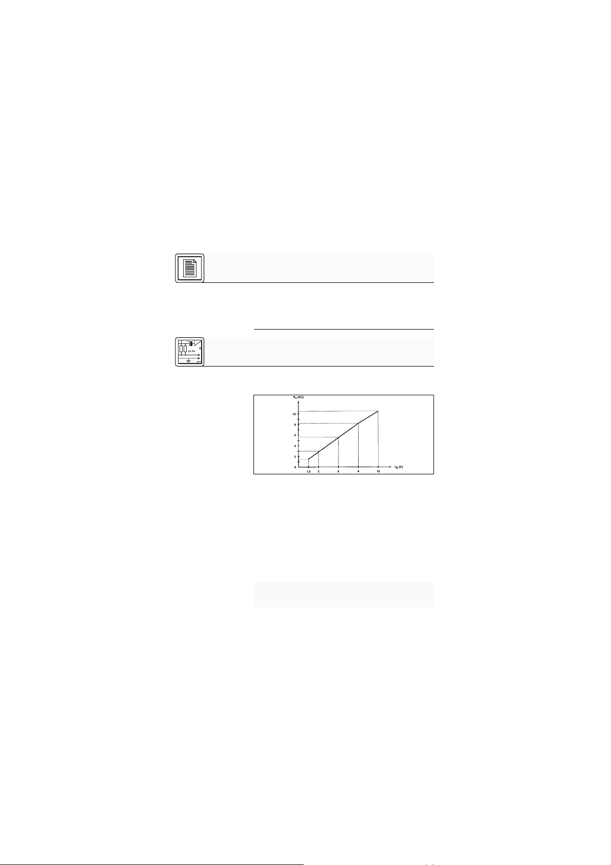
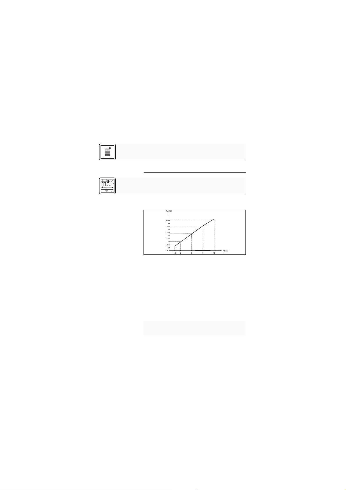
Abb. 1: Optimaler
Speisewiderstand als
Funktion der
Speisespannung
Siehe Abb. 2.
Wicht ig!
• Kabel 3 m lang, mit Phantomspeiseadapter mit integriertem 3-poligen XLR-Stecker. Zum Anschluss an
Mischpulte oder Tonbandgeräte mit 9 bis 52 V Phantomspeisung, oder - via ein AKG Phantomspeisegerät - an Audiogeräte ohne Phantomspeisung.
Alle CK 77 WR oc-Varianten sind für eine Speisespannung von 1,5 V bis 12 V ausgelegt.
1. St ellen Sie den optimalen Speisewid erstand fest. Dieser hängt von der Speisespannung ab:
Speisespannung U
B
(V) Speisewiderstand RS(kΩ)
1,5 1,5
3 3,0
6 5,6
9 8,2
12 10,5
2. Stellen Sie fest, welchen Steckertyp Sie benötigen,
und löten Sie den Stecker an das Mikrofonkabel an.
Die genaue Steckerbeschaltung entnehmen Sie bitte
der Bedienungsanleitung des Gerätes, an das Sie
das Mikrofon anschließen möchten.
1 Beschreibung
2 Anschluss
2 Anschluss
5
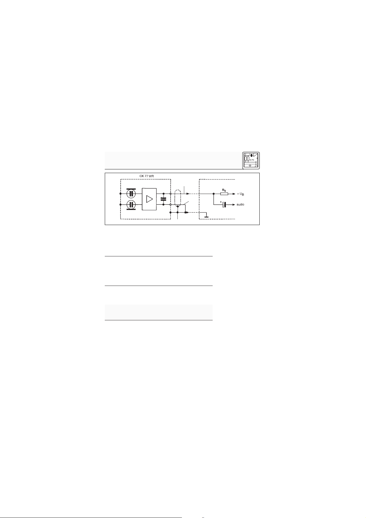
1 =rot
2 = blau
3 = Abschirmung
+U
B
= Speisespannung und Audio Inphase
Sie können diese beiden Varianten an jeden AKG
Taschensender mit 3-poliger Mini XLR-Eingangsbuchse
anschließen.
Näheres dazu finden Sie in der Bedienungsanleitung
Ihres Taschensenders.
Das C 577 WR ist für Universal-Phantomspeisung von 9
- 52 Volt (nach DIN 45596/IEC 268-15) ausgelegt.
Wenn Sie andere als die von AKG empfohlenen
Speisegeräte verwenden, kann das Mikrofon
beschädigt werden und erlischt die Garantie.
1. Stecken Sie den Phantomspeiseadapter (1) am Mikrofonkabel an einen symmetrischen XLR-Mikrofoneingang mit Phantomspeisung an.
2. Schalten Sie die Phantomspeisung ein. (Lesen Sie
dazu in der Betriebsanleitung des jeweiligen Gerätes
nach.)
2.2 CK 77 WR L,
L/ p
2.3 C 5 7 7 WR
Wicht ig!
2.3.1 Anschluss an
symmetrische
Eingänge
Siehe Abb. 3.
Abb. 2: Schaltplan des CK 77 WR
3
2
1

2 Anschluss
6
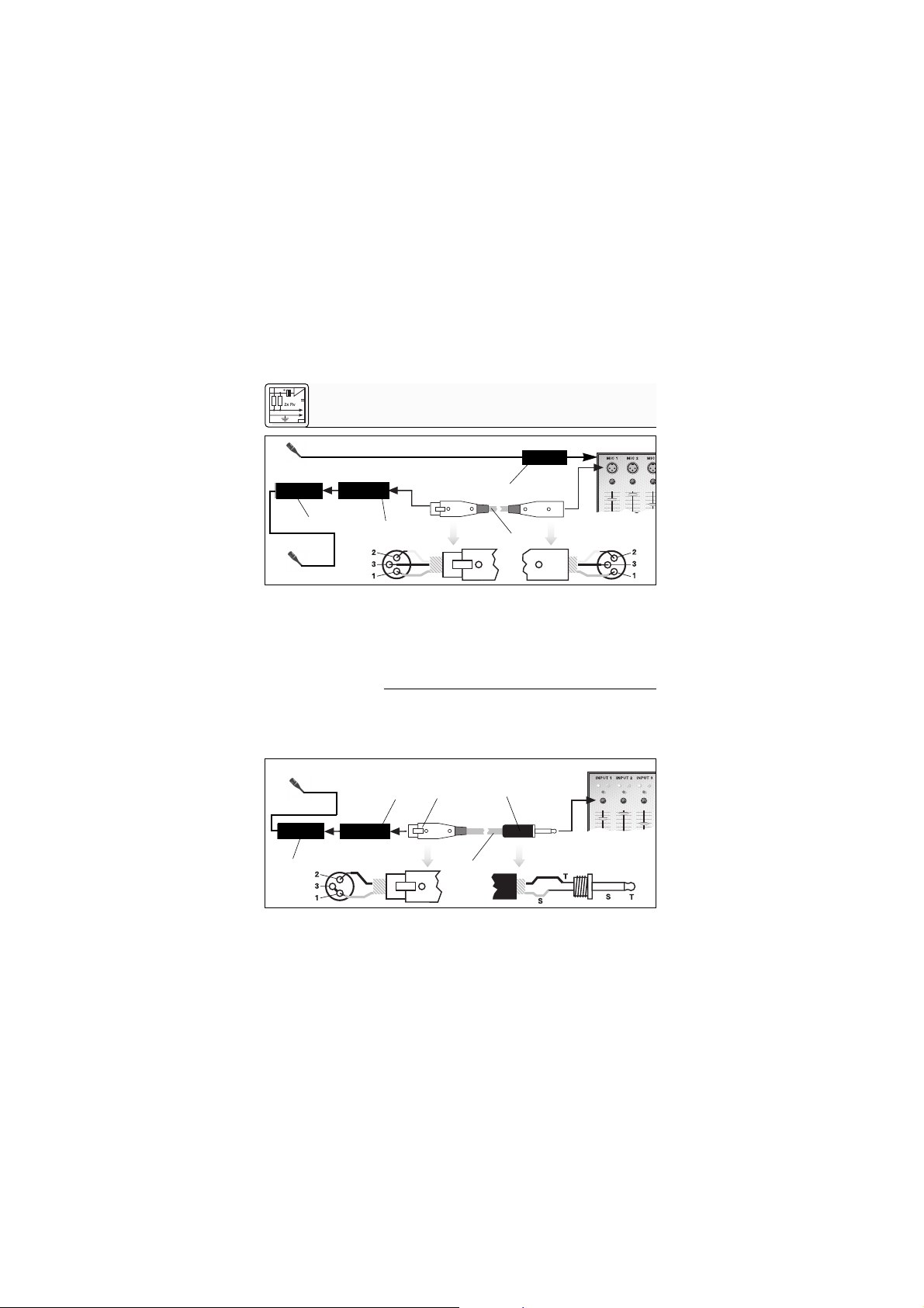
2.3.2 Anschluss an
asymme trische
Eingänge
Siehe Abb. 4.
3. Wenn Ihr Mischpult keine Phantomspeisung be-
sitzt, stecken Sie den Phantomspeiseadapter (1) an
ein optionales AKG-Phantomspeisegerät (2) (N 62 E,
N 66 E, B 18) an und verbinden Sie das Phantom speisegerät mit Hilfe eines XLR- Kab els (3) (z.B. AKG MK 9/ 10 nicht mitgeliefert) mit einem symmet rischen Eingang.
Phantomspeisegeräte (2) von AKG können Sie auch an
einen asymmetrischen Eingang anschließen.
Verwenden Sie dazu ein Kabel (3) mit XLR-Stecker
(weiblich) und Mono-Klinkenstecker:
XLR
1
1
3
Phantom
XLR
Abb. 3: Anschluss an symmetrischen Eingang
2
XLR
Phantom
1
2
3
4
5
Abb. 4: Anschluss an asymmetrischen Eingang

2 Anschluss
7
1. Verbinden Sie im XLR-Stecker (4) mittels einer Drahtbrücke Stift 1 mit Stift 3 und mit d er Abschirmung.
2. Verbinden Sie die innere Ader des Kabels mit Stift 2
des XLR-Steckers (4) und der Spitze des Klinkensteckers (5).
Beachten Sie, dass asymmetrische Kabel Einstreuungen aus Magnetfeldern (von Netz- und Licht kabeln,
Elektromotoren usw.) wie eine Antenne aufnehmen
können. Bei Kabeln, die länger als 5 m sind, kann dies
zu Brumm- und ähnlichen Störgeräuschen führen.
Wenn Sie das Mikrofon im Freien verwenden, können Sie
den mitgelieferten Windschutz W 77 auf das Mikrofon
stecken, um zu starke Windgeräusche zu dämpfen.
Der große Vorteil eines an der Kleidung oder in der
Maske befestigten Mikrofons besteht darin, dass der
Abstand zwischen dem Mikrofon und dem Mund der
Anwenderin/des Anwenders unabhängig von deren/dessen Bewegungen immer gleich bleibt und damit fast
keine Pegelschwankungen zu befürchten sind. Die
Bewegungsfreiheit bleibt erhalten, die Hände bleiben
frei.
1. Klemmen Sie das Kabel unmittelbar hinter dem Mi-
Hinweis:
Hinweis:
3.1 Anwe ndung als
Lavalie rmikrofon
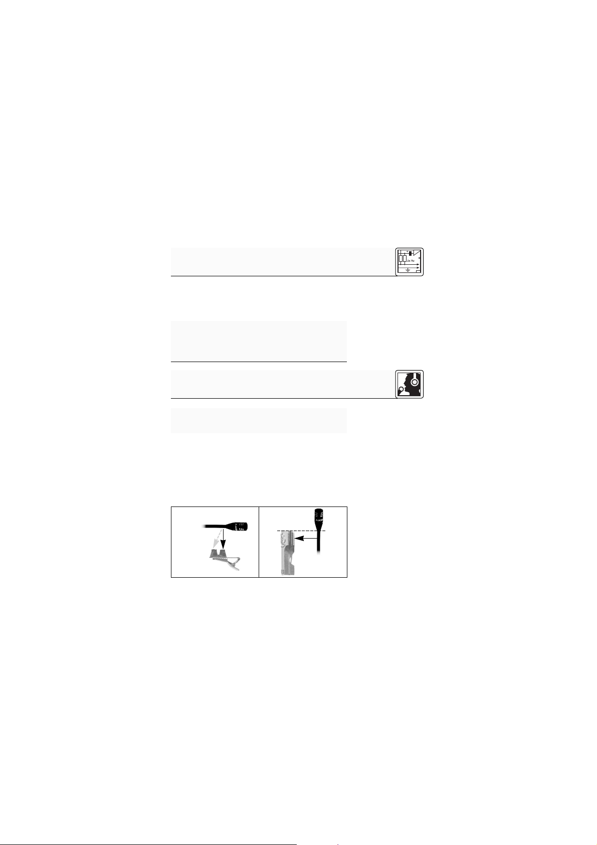
Abb. 5: Mikrofon an
Ansteckclip (a) und
Anstecknadel (b)
befestigen
3 Anw endung
a b
8
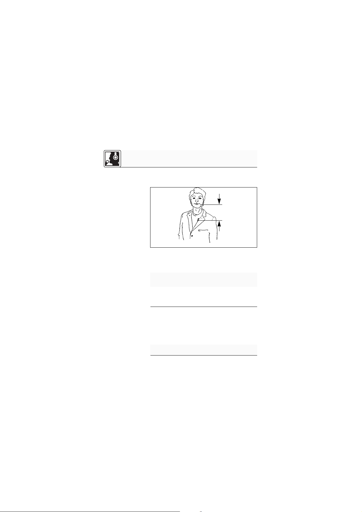
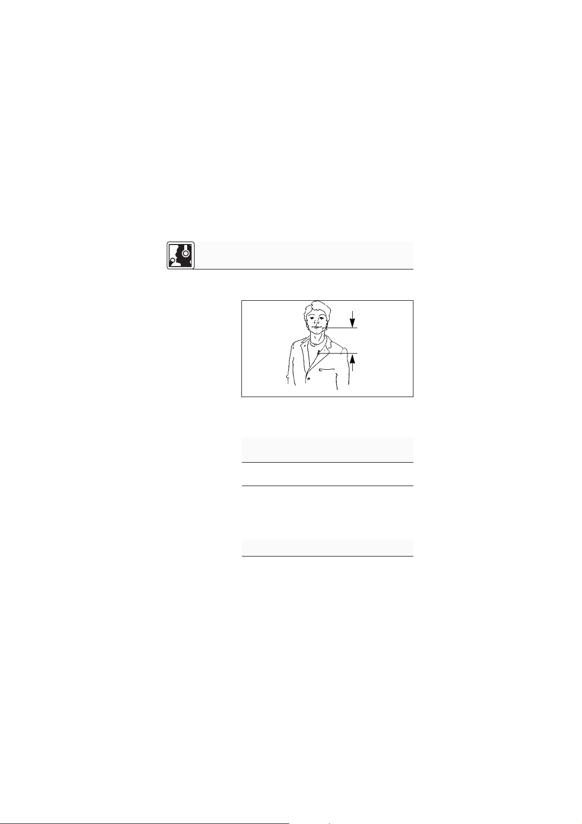
Abb. 6: Mikrofon
nahe beim Mund
befestigen
Hinweis:
3.2 Anwe ndung als
Aufnahme- oder
Stüt zmikrofon
Hinweis:
krofongehäuse in eine der Aufnahmerillen des mitgelieferten Ansteckclips H 40/1 (Abb. 5a) bzw. der mitgelieferten Anstecknadel H 41 (Abb. 5b).
2. Befestigen Sie das Mikrofon so nahe wie möglich
beim Mund der Rednerin/des Redners an der Kleidung, z.B. am Revers.
Je geringer der Abstand zwischen dem Mikrofon und
der Schallquelle, umso geringer ist die Gefahr akustischer Rückkop plungen.
3. Nur C 577 WR: Befestigen Sie den Phantomspei-
seadapter mit Hilfe der mitgelieferten Halterung H 16
am Hosengürtel.
1. Klemmen Sie das Kabel unmittelbar hinter dem Mikrofongehäuse in die entsprechende Aufnahme des
mitgelieferten Ansteckclips H 40/1 (Abb. 5a) bzw. der
mitgelieferten Anstecknadel H 41 (Abb. 5b).
2. B ef est igen Sie d as Mikrofon an einem geeigneten Dekorationsteil (z.B. Kulisse, Hintergrund, Vorhang o.ä.).
An glatten Oberflächen können Sie das Mikrofon
auch mit der mitgelieferten Klebemasse befestigen.
3 Anw endung
min.
9
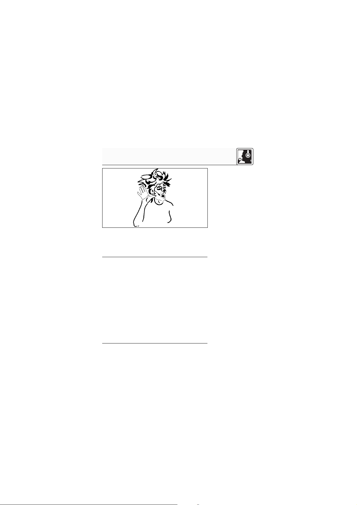
Befestigen Sie das Mikrofon in der Maske möglichst
nahe beim Mund.
Abb. 7 zeigt eine Möglichkeit der Positionierung.
Je nach den Erfordernissen der Inszenierung können Sie
das Mikrofon z.B. auch an der Stirn anbringen.
Mit der mitgelieferten Klebemasse oder dem Ansteckclip
H 40/1 können Sie das Mikrofon an vielen Instrumenten
(z.B. Streichinstrumenten, Gitarre, Blasinstrumenten)
befestigen.
Da sich das Mikrofon sehr nahe an der Schallquelle
befindet, brauchen Sie den Gain-Regler am Mischpult
nur wenig aufzudrehen. Beim Einsatz in
Beschallungsanlagen ist daher die Rückkopplungsgefahr sehr gering.
1. Um die optimale Position des Mikrofons am Instrument zu ermitteln, befestigen Sie das Mikrofon an
verschiedenen Stellen am Instrument und vergleic hen
Sie den Klang.
2. Wenn Sie das Mikrofon an einem Blasinstrument
montieren, können Sie den mitgelieferten Windschut z
W 77 auf das Mikrofon stecken, um zu starke Blasgeräusche zu dämpfen.
3.3 The ater,
Musical, Oper
Abb. 7: Mikrofon in
der Maske
integriert
3.4 Abnahm e von
Musikinstrumenten
3 Anw endung
10
Im Theaterbetrieb können die Mikrofonkappe und ihre
Schallöffnungen durch Schweiß und Schminke verschmutzt werden.
1. Schrauben Sie die Schutzkapp e vom Kabelmodul ab.
2. Reinigen Sie die Schutzkappe - am zweckmäßigsten
in einem Ultraschallbad (wie es Juweliere zur Reinigung von Schmuck verwenden).
3. Lassen Sie die Schutzkappe troc knen.
4. Schrauben Sie die Schutzkappe wieder auf das Kabelmodul.
Sollte das Mikrofon durch längere Verwendung direkt am
Körper und die damit verbundene Schweißbildung ausfallen, können Sie das Mikrofonelement austauschen,
ohne die Verkabelung vom Körper des Künstlers abnehmen zu müssen. Dies erspart den zeitaufwendigen
Mikrofontausch im oft hektischen Theaterbetrieb.
Ersatzelemente sind vom AKG Service erhältlich.
1. Schrauben Sie die Schutzkapp e ab.
2. Schrauben Sie das Mikrofonelement aus dem Kabelmodul aus.
3. Schrauben Sie das Ersatzelement in das Kabelmodul
ein.
4. Schrauben Sie die Schutzkappe wieder auf das Kabelmodul auf.
4 Reinigung
5 Service
6 Technische Daten
11
Arbeitsweise: Kondensatorwandler (Doppelmembransystem)
mit Permanentladung
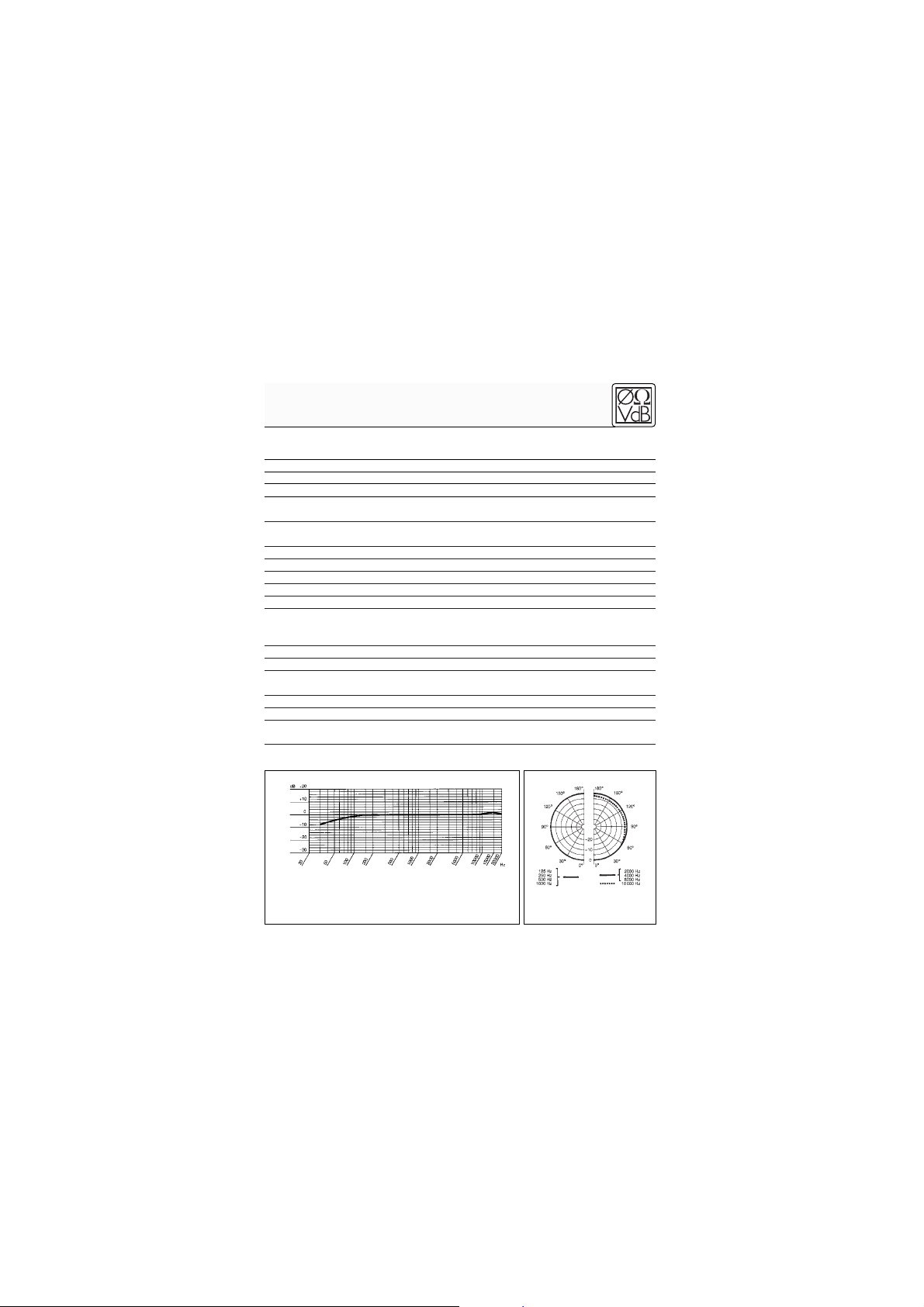
Richtcharakterisitik: Kugel
Übertragungsbereich: 20 - 20.000 Hz
Empfindlichkeit bei 1000 Hz: 8 mV/Pa = -42 dBV
Elektrische Impedanz: CK 77 WR: <3500 Ω
C 577 WR: <400 Ω
Empfohlene Lastimpedanz: CK 77 WR: ≥10 kΩ
C 577 WR: ≥2000 Ω
Äquivalentschalldruckpegel nach DIN 45412 (A-bew.): <26 dB-A
Signal/Rauschabstand (A-bew.): 68 dB
Grenzschalldruckpegel für k = 1 % : 133 dB
Betriebstemperatur: -20°C bis +60°C
Rel. Luftfeuchte: 99% (+20°C); 95% (+60°C)
Speisespannung: CK 77 WR: 1,5 bis 12 V DC
C 577 WR: 9 - 52 V Phantomspeisung nach
DIN 45596/IEC 268-15
Stromaufnahme: <0,6 mA
Abmessungen: 5,5 ø x 15,5 mm
Kabellänge: CK 77 WR: 1,5 m
C 577 WR: 3 m
Gewicht netto/brutto: 0,4 g / 85 g
Gehäuseoberfläche: matt-schwarz, hautfarben oder weiß
Dieses Produkt entspricht der Norm EN 50 082-1, vorausgesetzt, dass nachgeschaltete Audio-/Speisegeräte CE-konform sind.
Frequenzgang Polardiagramm
12
1.1 Precaut ion
1.2 Unpacking
1.3 Optional
Accessories for
the C 577 WR
1.4 CK 77 WR
Please make sure that the piece of equipment your
microphone will be connected to fulfills the safety regulations in force in your country and is fitted with a ground
lead.
Check that the package contains all the parts listed
above for your microphone. If anything is missing,
please contact your AKG dealer.
• MK 9/ 10 microphone cable: 10-m (30-ft.) 2-conductor
shielded cable w/male and female XLR c onnectors
• N 62 E, N 66 E, B 18 phantom p ower suppplies
The CK 77 WR is a professional miniature condenser
clip-on microphone with an omnidirectional polar
pattern. With its wide frequency range from 20 Hz to
20 kHz, low distortion at high sound pressure levels,
small size, and versatile accessories, the microphone is
an ideal choice for miking up musical instruments,
lecturers, actors, preachers, etc. Other applications
include TV and broadcast work as well as inconspicuous
spot miking in live recording.
The microphone features a dual-diaphragm transducer
for efficient suppression of cable noise and mechanical
noise that may occur when the microphone is used
directly on an instrument. The two diaphragms are electrically connected out of phase. Impacts will move both
diaphragms in the same direction so unwanted noise will
be canceled out. Sound will move the diaphragms in
opposite directions so the two output signals will add in
phase.
1 Precaution/ Descript ion
CK 7 7 WR
1 CK 77 WR microphone
1 W 77 windscreen
1 H 40/1 clip
1 H 41 tie pin
Adhesive compound
C 5 77 WR
1 C 577 WR microphone
1 W 77 windscreen
1 H 40/1 clip
1 H 41 tie pin
1 H 16 belt clip
Adhesive compound

13
The microphone capsule is a patented design that prevents perspiration and moisture from penetrating into
the transducer. A special clear plastic ring makes sure
that perspiration and makeup will not clog the sound
entries on the microphone body.
The microphone is fitted with a 1.5-m (5-ft.) cable with
either unterminated leads or a 3-pin mini XLR connector.
The microphone is available in three different colors and
will almost disappear when blended in with an actor's or
singer's makeup.
An external windscreen supplied with the microphone
reduces wind noise when using the microphone on an
open-air stage.
The C 577 WR is identical to the CK 77 WR, except that
it operates on 9 to 52 V universal phantom power to
DIN 45596/IEC 268-15 and is available in black only.
• Cable: 1.5 m (5 ft.), with unterminated leads. Supply
voltage: 1.5 to 12 VDC. Finish: matte black.
• Cable: 1.5 m (5 ft.), with unterminated leads. Supply
voltage: 1.5 to 12 VDC. Finish: white.
• Cable: 1.5 m (5 ft.), with unterminated leads. Supply
voltage: 1.5 to 12 VDC. Finish: flesh-color.
• Cable: 1.5 m (5 ft.), with 3-pin mini XLR connector for
use with AKG bodypack transmitters. Finish: matte
black.
• Cable: 1.5 m (5 ft.), with 3-pin mini XLR connector for
use with AKG bodypack transmitters. Finish: fleshcolor.
• Cable: 3 m (10 ft.), with phantom power adapter with
integrated 3-pin XLR connector. For direct connection to mixing consoles or recording devices with 9 to
52 V phantom power. Connects to audio equipment
1 Descript ion
1.5 C 5 7 7 WR
1.6 Versions
• CK 7 7 WR oc
• CK 7 7 WR oc/ w
• CK 7 7 WR oc/ p
• CK 7 7 WR- L
• CK 7 7 WR- L/ p
• C 5 77 WR
14
2.1 CK 77 WR oc,
oc/ p, oc/ w
Fig. 1: Optimum feed
resistance vs.
supply voltage.
Refer to fig. 2.
Impor tant!
with no phantom power via an AKG phantom power
supply.
All CK 77 WR oc versions have been designed for
powering with 1.5 VDC to 12 VDC.
1. Determine the optimum value for the feed resistor. It
depends on the supply voltage:
Supply voltage U
B
(V) Feed resistance RS(kΩ)
1.5 1.5
3 3.0
6 5.6
9 8.2
12 10.5
2. Check what type of connector you need and solder
the connector to the microphone cable.
For details on connector wiring, refer to the instruction manual of the device to which you intend to
connect your microphone.
1 Descript ion
2 Interfacing

2 Interfacing
15
1 =red
2 = blue
3 = shield
+UB = supply voltage and audio inphase
You can connect the CK 77 WR L and the CK 77 WR L/p
to any AKG bodypack transmitter with a 3-pin mini XLR
input.
For details, refer to the instruction manual of your bodypack transmitter.
The C 577 WR has been designed for universal phantom
powering from 9 to 52 V as per DIN 45596/IEC 268-15.
Using any power supply other than those recommended by AKG may damage your microphone and
will void the warranty.
1. Co nnect t he phantom power adapter (1) on the microphone cable to a balanced XLR microphone input
with phantom power.
2. Switch the phantom power on. (Refer to the instruction manual of the unit to which you connected your
microphone.)
2.2 CK 77 WR L,
L/ p
2.3 C 5 7 7 WR
Impor tant!
2.3.1 Conne ct ing
to Ba lanced Inputs
Refer to fig. 3 on
page 16.
Fig. 2: CK 77 WR circuit diagram.
3
2
1
2 Interfacing
16
2.3.2 Conne ct ing
to Unbalance d
Input s
Refer to fig. 4.
3. If your mixer provides no phantom power: Connect
the phantom power adapter (1) to an optional AKG
phantom power supply (2) (N 62 E, N 66 E, B 18) and
use an XLR cable (3) (e.g., an optional MK 9/10 from
AKG) to connect the phantom power supply to the
desired balanced input.
You may connect any AKG phantom power supply (2) to
an unbalanced input, too.
Use a cable (3) with a female XLR connector and TS jack
plug:
Fig. 3: Connecting to a balanced input.
XLR
1
1
3
Phantom
XLR
2
XLR
Phantom
1
2
3
4
5
Fig. 4: connecting to an unbalanced input.
2 Interfacing
17
1. On the XLR connector (4), add a wire bridge to
connect pin 1 to pin 3 and the cable shield.
2. Connect t he inside wire of the cable to pin 2 on the XLR
connect or (4) and the tip contact of t he jack plug (5).
Unbalanced cables may pick up interference from
stray magnetic fields near power or lighting cables,
electric motors, etc. like an antenna. This may introduce hum or similar noise when you use a cable that
is longer than 16 feet (5 m).
If you use the microphone in the open air you can slip the
supplied W 77 windscreen on the microphone to
attenuate wind noise.
The principal benefit of a microphone attached to the
user's clothes or integrated in their makeup is that the
microphone will maintain a constant working distance
independently of the user's movements and thus ensure
a constant output level. Also, a clip-on microphone
allows the user to move about freely and keeps their
hands free.
1. Insert the cable into one of the fixing grooves on the
Note :
Note :
3.1 Lavalier Miking
Fig. 5: Fixing the
microphone on the
clip (a) or tie pin (b).
3 Applicat ions
a b
18
Fig. 6: Attaching the
microphone near the
user's mouth.
Note :
3.2 Live Recording
and Spot Miking
Note :
supplied H 40/1 clip (se fig. 5a) or on the supplied
H 41 tie pin (see fig. 5b), at a point immediately behind
the microphone body.
2. Attach the microphone to the talker's clothes, e.g., on
the lapel, placing it as close as possible to t he t alker's
mouth.
The smaller the distance between the microphone
and the sound source, the higher the usable gain before feedback.
3. C 577 WR only: Fix the phantom power adapter to
the belt with the H 16 belt clip.
1. Insert the cable into one of the fixing grooves on the
supplied H 40/1 clip (se fig. 5a) or on the supplied
H 41 tie pin (see fig. 5b).
2. Fix the microphone on a suitable part of the stage
decoration such as a flat, backdrop, curtain, etc.
To fix the microphone to a hard surface, use the supplied adhesive compound .
3 Applicat ions
min.

19
Fix the microphone on the user's head, as close as possible to the mouth, and blend it in with the makeup.
Many engineers place the microphone as shown in fig. 7.
Depending on the requirements of the production at
hand, you may also attach the microphone, e.g., to the
performer' s forehead.
You can use the supplied adhesive compound or H 40/1
clip to fasten the microphone on various instruments
(e.g., string instruments, guitar, wind instruments).
Since the microphone will sit very close to the sound
source, you can set the gain control on the console to a
rather low level. This means that the feedback risk in a
live situation will be very low.
1. To find the best position of the microphone on the instrument, try several different places on the instrument and compare the sounds.
2. If you mount the microphone on a wind instrument,
consider slipping the supplied W 77 windscreen on
the microphone to reduce blowing noise.
3.3 The ater,
Musical, Opera
Fig. 7: Microphone
integrated in performer's makeup.
3.4 Miking up
Musical
Instrument s
3 Applicat ions
20
In theater work, the microphone grill and sound entry
may become clogged by makeup and perspiration.
1. Unscrew the grill from the cable module CCW.
2. Place the grill in an ultrasonic cleaning bath of the
type jewelers use to c lean jewelry. This is t he best way
to clean even the smallest orifices in the grill.
3. Allow the grill to dry.
4. Screw the grill back on the cable module.
If the microphone fails due to condensation caused by
perspiration after long periods of use on the body, you
can replace the transducer element in the field. To replace the transducer element, you do not even need to
remove the microphone from the actor’s body.
Therefore, this method is faster than replacing the entire
microphone.
Replacement transducer elements are available from
AKG Service.
1. Unscrew the grill from the cable module.
2. Unscrew the transducer element from the cable
module.
3. Screw the replacement transducer element on the
cable module.
4. Replace the grill.
4 Cleaning
5 Service
 Loading...