

Page 1
compact
Bedienungshinweise. . . . . . . . . . . . . . . . . . . . . . S. 2
Bitte vor Inbetriebnahme des Gerätes lesen!
User Instructions. . . . . . . . . . . . . . . . . . . . . . . . p. 12
Please read the manual before using the equipment!
Mode d’emploi . . . . . . . . . . . . . . . . . . . . . . . . . . p. 22
Veuillez lire cette notice avant d’utiliser le système!
Istruzioni per l’uso. . . . . . . . . . . . . . . . . . . . . . . p. 32
Prima di utilizzare l’apparecchio, leggere il manuale!
Modo de empleo . . . . . . . . . . . . . . . . . . . . . . . . p. 42
Antes de utilizar el equipo, lea por favor el manual!
Instruções de uso . . . . . . . . . . . . . . . . . . . . . . . p. 52
Favor leia este manual antes de usar o equipamen
to!
Page 2
1 Sicherheit und Umwelt
1. Schütten Sie keine Flüssigkeiten auf das Gerät und
lassen Sie keine sonstigen Gegenstände in die
Geräteöffnungen fallen.
2. Stellen Sie das Gerät nicht in der Nähe von Wärmequellen wie z.B. Radiatoren, Heizungsrohren, Verstärkern
usw. auf und setzen Sie es nicht direkter Sonneneinstrahlung, starker Staub- und Feuchtigkeitseinwirkung, Regen, Vibrationen oder Schlägen aus.
3. Die Verpackung ist recyclierbar. Entsorgen Sie die
Verpackung in einem dafür vorgesehenen Sammelsystem.
2 Beschreibung
2.1 Einleitung
2.2 Mikrofone
Siehe Fig. 9 - 13.
2
Herzlichen Glückwunsch zum Kauf eines Discreet
Acoustics Moduls. Die Discreet Acoustics Compact
Serie umfasst 4 Schwanenhalsmikrofone und 1
Hängemikrofon sowie spezielles Zubehör für jede
Anwendung und jeden Einsatzort.
CGN 321 E (Best.-Nr. 2965Z0001): 380 mm langes
Schwanenhalsmikrofon mit integriertem XLRPhantomspeiseadapter DPA. Mikrofon mit
nierenförmiger Richtcharakteristik und SchaumstoffWindschutz.
CGN 323 E (Best.-Nr. 2965Z0002): 380 mm langes
Schwanenhalsmikrofon mit integriertem XLRPhantomspeiseadapter DPA. Mikrofon mit hypernierenförmiger Richtcharakteristik und SchaumstoffWindschutz.
CGN 521 E (Best.-Nr. 2965Z0003): 576 mm langes
Schwanenhalsmikrofon mit integriertem XLRPhantomspeiseadapter DPA. Mikrofon mit
nierenförmiger Richtcharakteristik und SchaumstoffWindschutz.
CGN 523 E (Best.-Nr. 2965Z0004): 576 mm langes
Schwanenhalsmikrofon mit integriertem XLRPhantomspeiseadapter DPA. Mikrofon mit hypernierenförmiger Richtcharakteristik und SchaumstoffWindschutz.
Page 3
2 Beschreibung
CHM 21 (Best.-Nr. 2965Z0005): Hängemikrofon mit
Federklemme und 10 m langem Spezialkabel mit
XLR-Phantomspeiseadapter DPA. Nierenförmige
Richtcharakteristik.
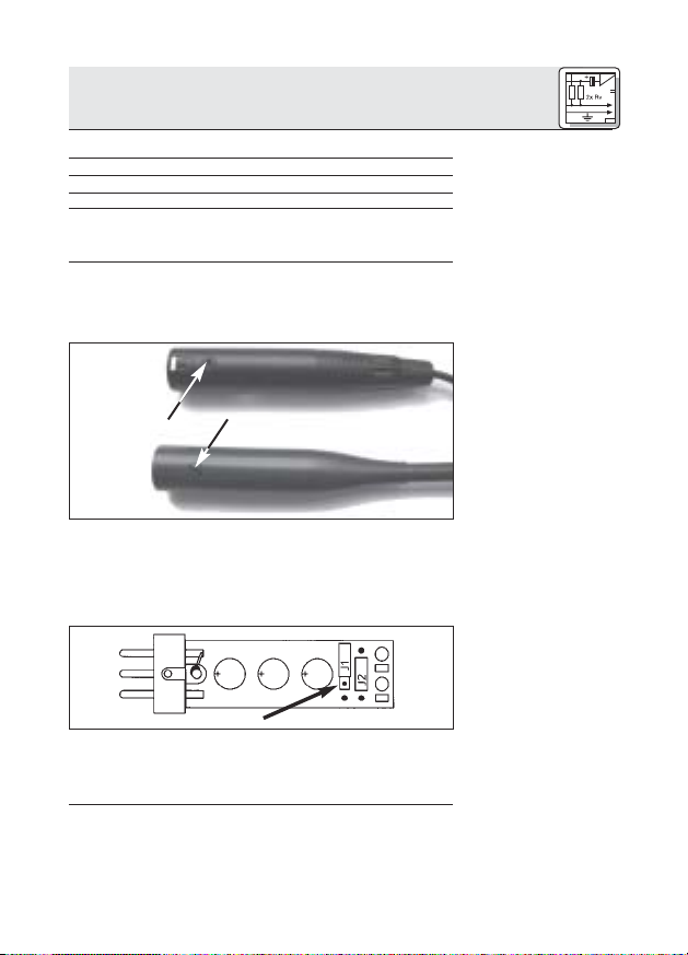
Verwenden Sie immer den mitgelieferten Windschutz
(außer der Windschutz würde optisch stören). Er schützt
das Mikrofon vor Staub und Feuchtigkeit und unterdrückt
Pop- und Windgeräusche weitgehend.
Batteriespeisegerät B 18 für alle Discreet Acoustics
Compact Mikrofone
Netzgeräte N 62 E, N 66 E für alle Discreet Acoustics
Compact Mikrofone
Montagesockel PS3 F-Lock für alle Discreet Acoustics
Compact Schwanenhalsmikrofone (nicht für CHM 21)
Elastische Halterung H 500 für alle Discreet Acoustics
Compact Schwanenhalsmikrofone (nicht für CHM 21)
Elastische Halterung H 600 für alle Discreet Acoustics
Compact Schwanenhalsmikrofone (nicht für CHM 21)
Stativanschluss SA 60 für alle Discreet Acoustics
Compact Schwanenhalsmikrofone (nicht für CHM 21)
Tischstative ST 1, ST 45 für alle Discreet Acoustics
Compact Schwanenhalsmikrofone (nicht für CHM 21)
3 Mikrofonanwendungen
Bitte beachten Sie, dass der Aufnahmewinkel sowohl den
maximalen Besprechungsabstand als auch die
abzunehmende Fläche beeinflusst. Je kleiner der
Aufnahmewinkel (Hyperniere), desto größer die maximale
Distanz zwischen Sprecher und Mikrofon, desto kleiner
aber die abzunehmende Fläche.
Ob Sie ein Nieren- oder Hypernierenmikrofon einsetzen,
hängt daher von der jeweiligen Anwendungssituation ab.
Siehe Fig. 14.
2.3 Windschutz
(2965Z2001)
2.4 Empfohlenes
Zubehör
Siehe Fig. 9.
Siehe Fig. 10.
Siehe Fig. 11.
Siehe Fig. 12.
Siehe Fig. 13.
Siehe Tabelle 1.
3
Page 4
3 Mikrofonanwendungen
Mikrofon
CGN 321 E
CGN 323 E
CGN 521 E
CGN 523 E
CHM 21
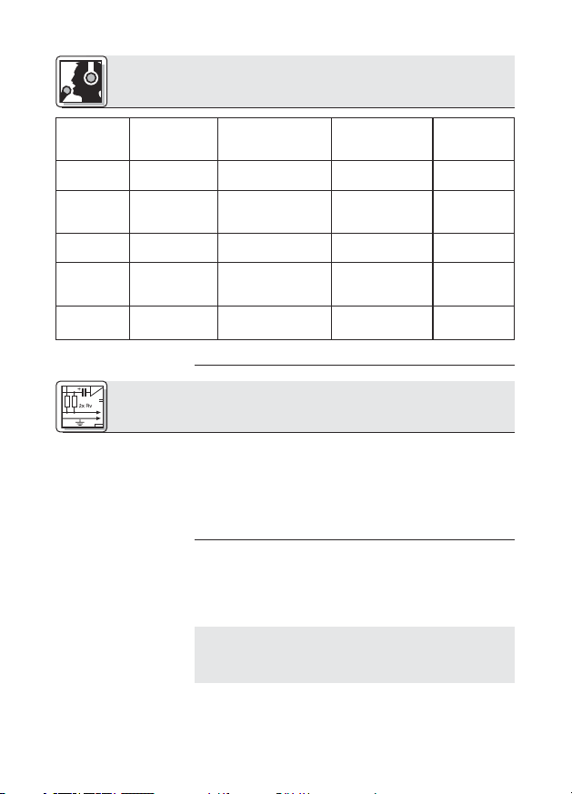
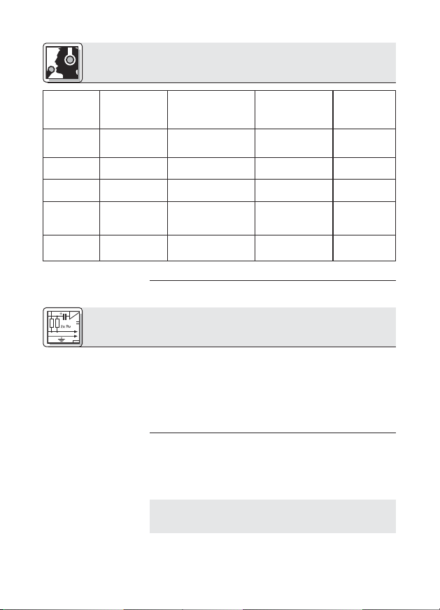
Tabelle 1: Mikrofonanwendungen
Richtcharakteristik
Niere
Hyperniere
Niere
Hyperniere
Niere
Lautsprecherposition
nur hinter dem
Mikrofon
seitlich bis schräg
hinter dem Mikrofon
nur hinter dem
Mikrofon
seitlich bis schräg
hinter dem Mikrofon
nur hinter dem
Mikrofon
4 Montage und Anschluss
4.1 Einleitung
4.2 Schwanenhalsmikrofone CGN .. E
Siehe Fig. 9 und 12.
Hinweis:
Siehe Fig. 10 und 11.
4
Alle Mikrofone der Discreet Acoustics Compact Serie
sind Kondensatormikrofone und benötigen daher eine
Stromversorgung (Phantomspeisung). Die Mikrofone
sind für den Anschluss an Mikrofoneingänge mit
Phantomspeisung (9 bis 52 V) ausgelegt. Anschluss an
Eingänge ohne Phantomspeisung siehe Kapitel 4.4.
1. Montieren Sie das Mikrofon mittels des optionalen
Montagesockels PS 3 F-Lock auf einer Tischplatte
oder mit dem optionalen Stativanschluss SA 60 auf
einem Boden- oder Tischstativ.
Zur besseren Körperschallunterdrückung können Sie
das Mikrofon auch mittels der optionalen elastischen
Lagerung H 500 oder H 600 in die Tischplatte
einbauen.
2. Schließen Sie das Mikrofon mittels eines geschirmten
Kabels an einen Mikrofoneingang mit
Phantomspeisung an.
Besprechungsabstand
30 - 60 cm
30 - 90 cm
30 - 60 cm
30 - 90 cm
1 - 3 m
Anwendung
Beschallung
Beschallung
Beschallung
Beschallung
Beschallung
Page 5
4 Montage und Anschluss
3. Wenn die Phantomspeisung Ihres Mischpults
schaltbar ist, schalten Sie sie ein. (Lesen Sie dazu die
Bedienungsanleitung Ihres Mischpults nach.)
Das Mikrofon erhält seine Versorgungsspannung
direkt aus der Phantomspeisung.
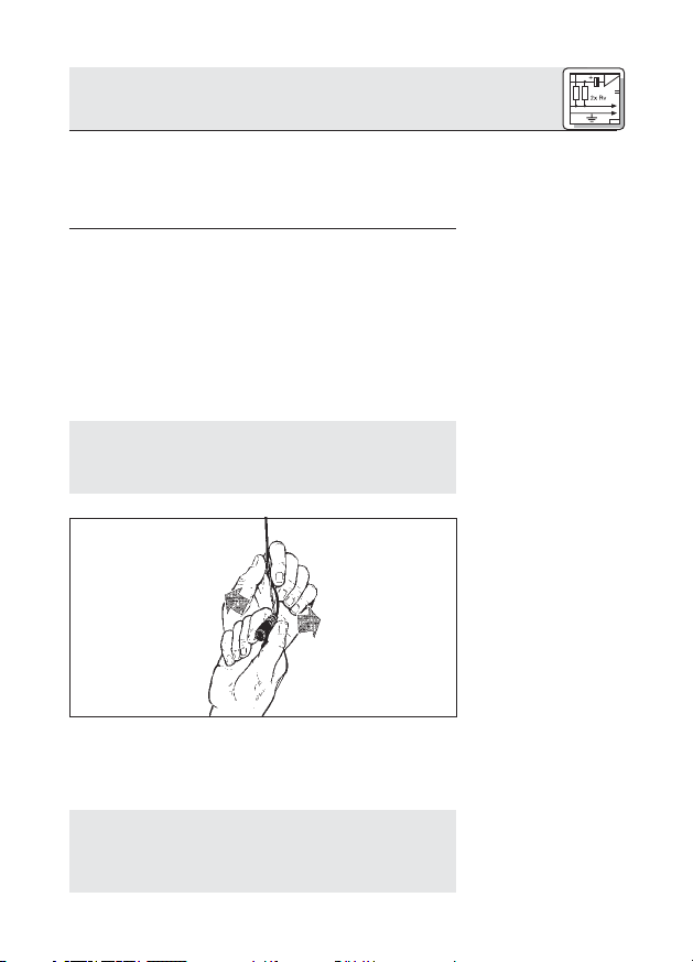
1. Streifen Sie vor der Montage das Kabel leicht mit
der Hand aus. Achten Sie darauf, das Kabel weder zu
knicken noch zu verdrehen.
2. Bringen Sie an der Decke einen geeigneten Haken an,
bzw. spannen Sie eine Leine quer durch den Raum.
3. Legen Sie das Kabel so über den Haken, bzw. die
Leine, dass das Mikrofon in der gewünschten Höhe
hängt.
4. Fixieren Sie das Kabel mit Isolierband.
Befestigen Sie das Kabel auf keinen Fall mit
einem Knoten am Haken! Dadurch würde sich das
Kabel mit der Zeit verdrehen und das Mikrofon wäre in
der Folge nicht mehr positionierbar.
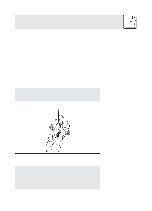
5. Halten Sie das Kabel mit einer Hand fest und drehen
Sie das Mikrofon vorsichtig in die gewünschte
Position.
• Das Kabel des CHM 21 verdreht sich bei
Temperaturschwankungen, z.B. durch die Wärme
von Scheinwerfern.
• Der Verdrehungswinkel hängt sowohl von der
4.3 Hängemikrofon
CHM 21
Wichtig!
Fig. 1: Ausrichten des
Mikrofons
Siehe Fig. 1.
Hinweis:
5
Page 6
4 Montage und Anschluss
4.3.1 Mikrofon
stabilisieren
4.3.2 Anwendungshinweise
Umgebungstemperatur als auch von der Länge des
Kabels ab. Je kürzer das Kabel, umso geringer die
Verdrehung.
• Wenn Sie mit Scheinwerfern arbeiten, schalten
Sie diese ein, bevor Sie das Mikrofon ausrichten.
• Nach dem Ausschalten der Scheinwerfer wird sich
das Mikrofon verdrehen. Wenn Sie die Scheinwerfer
wieder einschalten, dreht sich das Mikrofon in die
selbe Position zurück, die Sie vorher eingestellt
haben.
Um die Mikrofonposition zu stabilisieren,
1. Fädeln Sie eine Angelschnur (durchsichtige
Nylonleine) entsprechender Länge durch die Öse an
der Federklemme des CHM 21.
2. Befestigen Sie die Angelschnur so an zwei
gegenüberliegenden Wänden, dass die Angelschnur
gerade genug Zug nach unten ausübt, um das
Mikrofon seitlich zu fixieren.
6
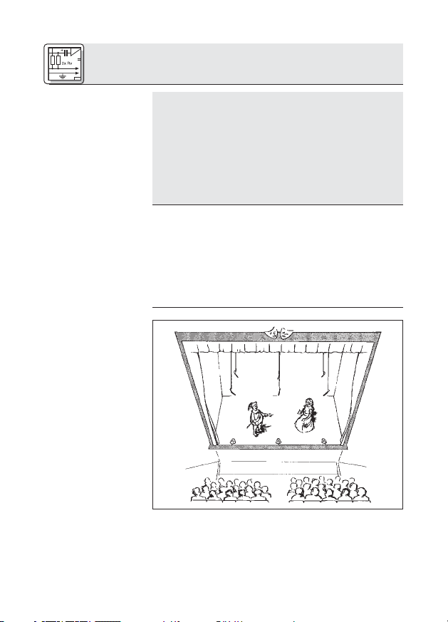
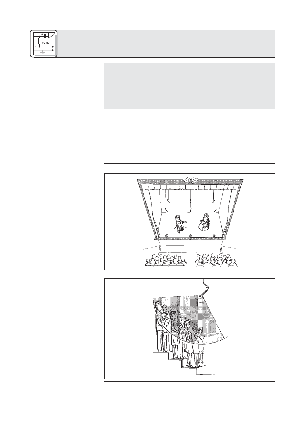
Fig.2: Theater-
beschallung
Page 7
4 Montage und Anschluss
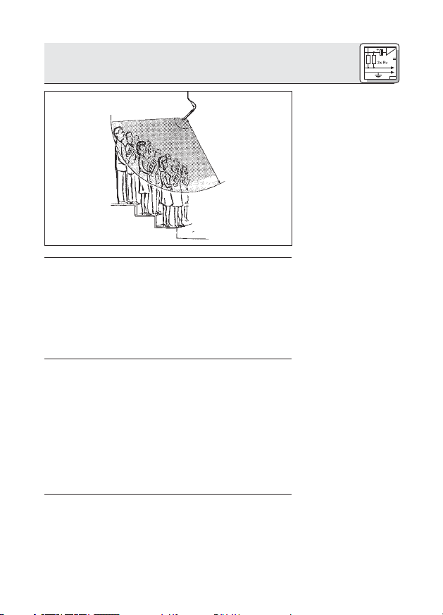
Fig. 3: Chorabnahme
1. Schließen Sie das Mikrofon mittels eines geschirmten
Kabels an einen Mikrofoneingang mit
Phantomspeisung an.
2. Wenn die Phantomspeisung Ihres Mischpults
schaltbar ist, schalten Sie sie ein. (Lesen Sie dazu die
Bedienungsanleitung Ihres Mischpults nach.)
Das Mikrofon erhält seine Versorgungsspannung
direkt aus der Phantomspeisung.
Wenn Ihr Mischpult keine Phantomspeisung besitzt,
schalten Sie ein Phantomspeisegerät zwischen Mikrofoneingang und Phantomspeiseadapter DPA. Wir
empfehlen die optionalen AKG-Speisegeräte B 18,
N 62 E und N 66 E.
Es ist aber auch möglich, symmetrische und
asymmetrische Mikrofoneingänge mit Phantomspeisung
nach DIN 45596 durch einen qualifizierten Techniker
nachrüsten zu lassen. Diese Norm schreibt eine positive
Spannung von 12, 24 oder 48 Volt an den NF-Leitungen
gegen die Kabelabschirmung vor.
4.3.3 AudioAnschluss
4.4 Stromversorgung bei
Eingängen ohne
Phantomspeisung
7
Page 8
4 Montage und Anschluss
Symmetrische
4.4.1
Eingänge
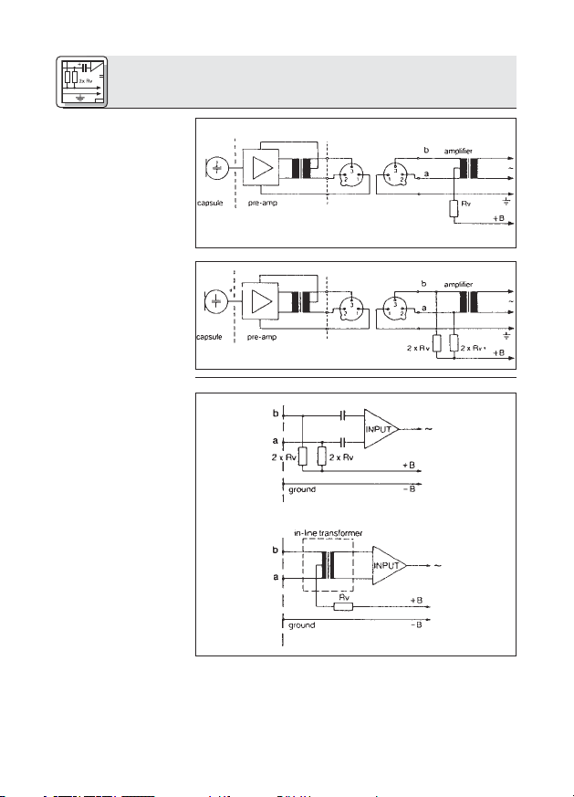
Fig. 4: Schaltung mit
Eingangsübertrager
mit Mitten-
anzapfung (erdfrei)
Fig. 5: Schaltung mit
Eingangsübertrager
ohne Mitten-
anzapfung (erdfrei)
4.4.2
Asymmetrische
Eingänge
Fig. 6: Asymmetri-
sche Eingangsstufe
8
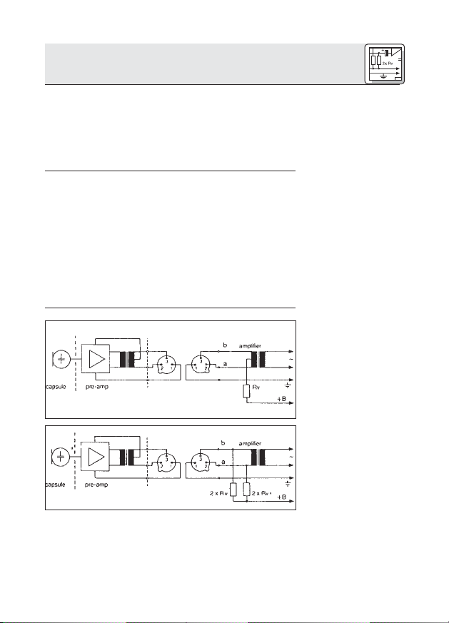
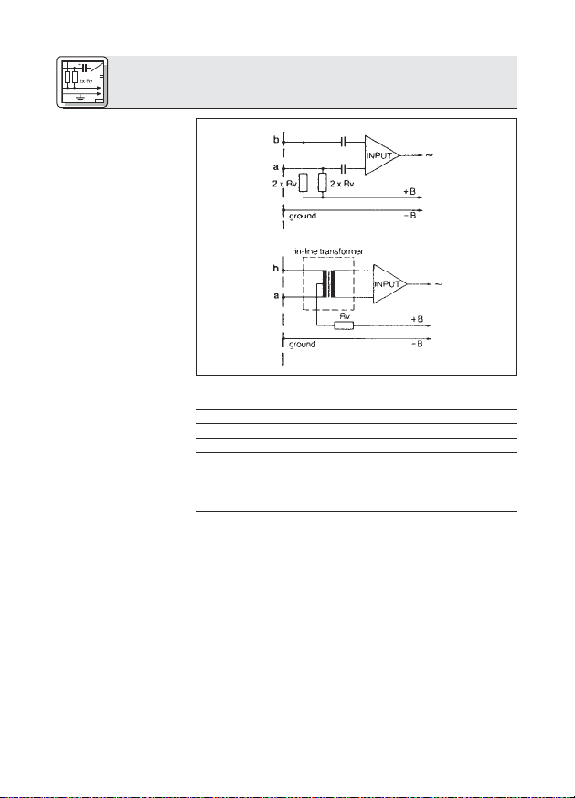
Sind die Mischpulteingänge geerdet oder keine
Eingangsübertrager vorhanden, müssen Sie entweder
Kondensatoren oder zusätzliche Transformatoren in die
NF-Leitungen einfügen, um eine Beeinträchtigung der
Eingangsstufe durch Leckströme zu verhindern.
Page 9
4 Montage und Anschluss
U= Rv 2 x Rv*
12V ±2V 330 Ω 680 Ω
24V ±2V 680 Ω 1200 Ω
48V ±4V 3300 Ω 6800 Ω
* Die Widerstände 2xRv dürfen aus Gründen der
Symmetrie max. 0,5% Toleranz aufweisen.
Der Phantomspeiseadapter DPA ist mit einer Bassabschwächung zur Unterdrückung tieffrequenter
Störgeräusche ausgestattet.
CHM 21
CGN ... E
1. Lösen Sie die Befestigungsschraube am Mikrofon
bzw. Phantomspeiseadapter DPA.
2. Ziehen Sie den Print VORSICHTIG aus dem Gehäuse
heraus.
3. Zum Aktivieren der Bassabschwächung stecken Sie
die Drahtbrücke J1 in das mittlere Kontaktpaar am
Print ein.
Tabelle 2: Normwerte
für Rv (bzw. 2xRv)
4.5 Bassabschwächung
Fig. 7: Befestigungsschraube
Siehe Fig. 7.
Fig. 8: Print DPA
Siehe Fig. 8.
9
Page 10
5 Technische Daten
Mikrofon CGN 321 E CGN 323 E
CGN 521 E CGN 523 E CHM 21
Arbeitsweise Kondensatormikrofon mit Permanentladung
Richtcharakteristik Niere Hyperniere Niere
Übertragungsbereich 70-18.000 Hz 50-19.000 Hz 70-18.000 Hz
Empfindlichkeit 18 mV/Pa 12 mV/Pa 18 mV/Pa
Ⳏ -35 dBV* Ⳏ -38 dBV* Ⳏ -35 dBV*
Grenzschalldruckpegel
(k = 1%) 125 dB 125 dB 125 dB
Äquivalentschalldruckpegel <21 dB-A <21 dB-A <21 dB-A
Signal/Rauschabstand
(A-bew.) >73 dB >73 dB >73 dB
Elektrische Impedanz <600 Ω <600 Ω <600 Ω
Empfohlene Lastimpedanz
Stromversorgung 9-52 V Phantomspeisung nach DIN 45596
Stromaufnahme <3 mA <3 mA <3 mA
Anschlussstecker XLR-3 XLR-3 XLR-3
Oberfläche dunkelgrau matt dunkelgrau matt dunkelgrau matt
Abmessungen 13,5 x 380 mm 13,5 x 380 mm
(Kapseldurchmesser x l) 13,5 x 580 mm 13,5 x 580 mm 13,5 x 55 mm
Netto-/Bruttogewicht 160/480 g 160/480 g
Bestellnummer 2965Z0001 2965Z0002
* bezogen auf 1 V/Pa
Dieses Produkt entspricht der Norm EN 50082-1, vorausgesetzt, dass die nachgeschalteten Audio-/Speisegeräte CE-konform sind.
>2000 Ω >2000 Ω >2000 Ω
(Adapter DPA integriert)
170/500 g 170/500 g 20/480 g
2965Z0003 2965Z0004 2965Z0005
10
Page 11
5 Technische Daten
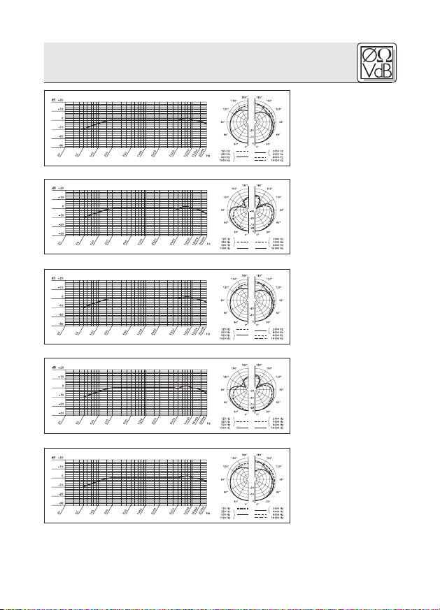
Frequenzgang &
Polardiagramm
CGN 321 E
Frequenzgang &
Polardiagramm
CGN 323 E
Frequenzgang &
Polardiagramm
CGN 521 E
Frequenzgang &
Polardiagramm
CGN 523 E
Frequenzgang &
Polardiagramm
CHM 21
11
Page 12
1 Safety and Environment
1. Do not spill any liquids on the equipment and do not
drop any objects through the ventilation slots in the
equipment.
2. Do not place the equipment near heat sources such
as radiators, heating ducts, or amplifiers, etc. and do
not expose it to direct sunlight, excessive dust, moisture, rain, mechanical vibrations, or shock.
3. The packaging of the equipment is recyclabe. To dispose of the packaging, make sure to use a collection/recycling system provided for that purpose and
observe local legislation relating to waste disposal
and recycling.
2 Description
2.1 Introduction
2.2 Microphones
Refer to figs. 9 to 14.
12
Thank you for purchasing a Discreet Acoustics
module. The Discreet Acoustics Compact Series comprises four gooseneck microphones, one flown microphone, and dedicated accessories for every application
and every type of venue.
CGN 321 E (order no. 2965Z0001): 380-mm (15-in.) cardioid gooseneck microphone with integrated DPA XLR
phantom power adapter and external foam windscreen.
CGN 323 E (order no. 2965Z0002): 380-mm (15-in.)
hypercardioid gooseneck microphone with integrated
DPA XLR phantom power adapter and external foam
windscreen.
CGN 521 E (order no. 2965Z0003): 576-mm (23-in.) cardioid gooseneck microphone with integrated DPA XLR
phantom power adapter and external foam windscreen.
CGN 323 E (order no. 2965Z0004): 576-mm (23-in.)
hypercardioid gooseneck microphone with integrated
DPA XLR phantom power adapter and external foam
windscreen.
CHM 21 (order no. 2965Z0005): cardioid flown microphone with spring clamp and 10-m (33-ft.) special cable
with DPA XLR phantom power adapter.
Page 13
2 Description
Always use the supplied windscreen (unless it would be
too visually obtrusive). It protects the microphone from
dust and moisture, and reduces pop and wind noise to a
minimum.
B 18 battery power supply for all Discreet Acoustics
Compact microphones.
N 62 E, N 66 E AC power supplies for all Discreet
Acoustics Compact microphones.
PS3 F-Lock panel mount socket for all Discreet
Acoustics Compact gooseneck microphones (not for
CHM 21).
H 500 shock mount for all Discreet Acoustics Compact
gooseneck microphones (not for CHM 21).
H 600 shock mount for all Discreet Acoustics Compact
gooseneck microphones (not for CHM 21).
SA 60 stand adapter for all Discreet Acoustics Compact
gooseneck microphones (not for CHM 21).
ST 1, ST 45 table stands for all Discreet Acoustics
Compact gooseneck microphones (not for CHM 21).
3 Microphone Applications
Note that both the maximum working distance and the
area covered by the microphone depend on the pickup
angle. The smaller the pickup angle (hypercardioid), the
longer the maximum distance between the talker and the
microphone and the smaller the area covered by the
microphone.
Whether a cardioid or hypercardioid capsule will give the
best results therefore depends on the specific application
situation).
2.3 Windscreen
(2965Z2001)
2.4 Optional
Accessories
Refer to fig. 9.
Refer to fig.10.
Refer to fig.11.
Refer to fig.12.
Refer to fig.13.
Refer to Table 1.
13
Page 14
3 Microphone Applications
Microphone
CGN 321 E
CGN 323 E
CGN 521 E
CGN 523 E
CHM 21
Table 1: Microphone applications.
Polar Pattern
Cardioid
Hypercardioid
Cardioid
Hypercardioid
Cardioid
Speaker position
Beinde the microphone only
90° to 135° off
microphone axis
Behind the microphone only
90° to 135° off
microphone
axis
Behind the microphone only
* Depending upon Acoustic environment
4 Installation and Connection
4.1 Introduction
4.2 CGN .. E
Gooseneck
Microphones
Refer to figs. 9 and 12.
Refer to figs. 10 and 11.
14
All Discreet Acoustics Compact microphones are condenser microphones and therefore require a power supply
(phantom power). The microphones have been designed
for connection to microphone inputs with 9 to
52 V phantom power. To connect Discreet Acoustics
Compact microphones to inputs without phantom power,
refer to Section 4.4.
1. Use the optional PS 3 F-Lock panel mount socket to
install the microphone in a tabletop or an optional
SA 60 stand adapter to mount the microphone on a
floor or table stand.
Note:
For even better vibrational noise rejection, you can fix
the microphone to the tabletop with an optional H 500
or H 600 shock mount.
2. Use a shielded cable to connect the microphone to a
microphone input with phantom power.
Working
distance
30 to 60 cm*
(1 to 2 feet)
30 to 90 cm*
(1 to 3 feet)
30 to 60 cm*
(1 to 2 feet)
30 to 90 cm*
(1 to 3 feet)
1 to 3 m*
(3.5 to 10 feet)
Application
Sound system
Sound system
Sound system
Sound system
Sound system
Page 15
4 Installation and Connection
3. If the phantom power on your mixing console is
switchable, switch the phantom power on. (Refer to
the instruction manual for your mixing console.)
The microphone is powered directly from the phantom power source on the console.
1. Prior to installing the microphone, straighten the
cable by carefully pulling it through your fingers. Make
sure not to buckle or twist the cable. Let hang for 1 day to
untwist.
2. Fasten a hook to the ceiling, use an existing hook, or
stretch a fishing line across the hall.
3. Pass the cable through the hook or over the line so
that it will hang at the desired height.
Do not tie a knot into the cable to hang it on the
hook. This may cause the cable to twist and misalign
the microphone after a while.
5. Hold the cable with one hand and turn the microphone carefully into the desired position.
• The cable on the CHM 21 will twist as the ambient
temperature changes, e.g., in the heat generated by
spotlights.
• The angle of twist depends both on the ambient temperature and the cable length. The shorter the cable,
the smaller the amount of twist.
4.3 CHM 21 Flown
Microphone
Important!
Fig. 1: Aligning the
microphone.
Refer to fig. 1.
Note:
15
Page 16
4 Installation and Connection
• If you use spotlights, be sure to turn them on
before aligning the microphone.
• When you turn the spotlights off, the microphone will
rotate out of alignment. Upon turning the spotlights
back on, the microphone should rotate back into its
original position.
4.3.1 Stabilizing
the Microphone
4.3.2 Applications
To stabilize the microphone,
1. Leave an appropriate length of fishing line through the
eyelet on the spring clamp of the CHM 21.
2. Fix the fishing line to two opposite walls so as to create just enough downward pull to steady the microphone laterally.
Fig. 2: Theater stage
miking
Fig. 3: Miking up a
16
choir
Page 17
4 Installation and Connection
1. Use a shielded balanced cable to connect the microphone to a microphone input with phantom power.
2. If the phantom power on your mixing console is
switchable, switch the phantom power on. (Refer to
the instruction manual for your mixing console.)
The microphone is powered directly from the phantom power source.
If your mixer has no phantom power, insert an external
phantom power supply between the DPA phantom power
adapter and mixer input. We recommend the optional
B 18, N 62 E, or N 66 E power supplies from AKG. Using
any power supplies not recommended by AKG may
damage your microphone and voids the warranty.
You may also consider having a qualified technician
retrofit a phantom power supply as per DIN 45596 to balanced or unbalanced mixer inputs. The DIN 45596 standard specifies a positive voltage of 12, 24, or 48 V on the
audio lines versus the cable shield.
If your equipment inputs are grounded or transformerless, wire either capacitors or extra transformers into the
audio lines as shown in fig. 9 above in order to prevent
any current leakage into the input stage.
4.3.3 Audio
Connection
4.4 Connecting to
Inputs without
Phantom Power
4.4.1 Balanced
Inputs
Fig. 4: Input transformer with center
tap (ungrounded)
Fig. 5: Input transformer with no
center tap
(ungrounded)
17
Page 18
4 Installation and Connection
4.4.2 Unbalanced
Inputs
Fig. 6: Unbalanced
input stage
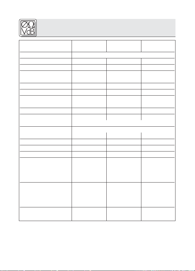
Table 2: Standard val-
ues for Rv and 2 x Rv
VDC Rv 2 x Rv*
12 V ±2 V 330 Ω 680 Ω
24 V ±4 V 680 Ω 1,200 Ω
48 V ±4 V 3,300 Ω 6,800 Ω
* In order to satisfy the DIN 45596 symmetry requirement,
make sure the actual values of the two resistors 2 x Rv
do not differ by more than 0.5%!
18
Page 19
4 Installation and Connection
The DPA phantom power adapter is equipped with a bass
cut filter to minimize low-frequency noise.
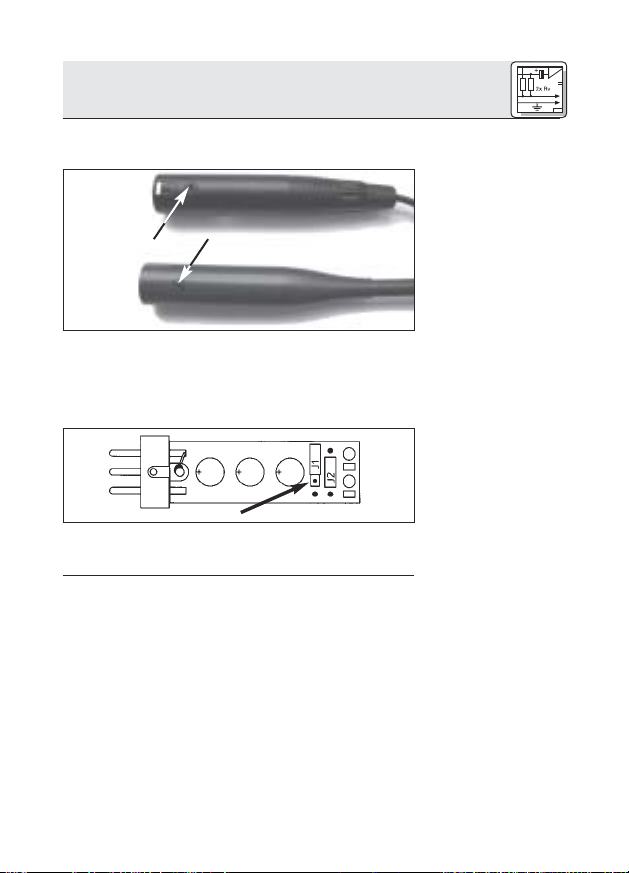
CHM 21
CGN ... E
1. Unscrew the fixing screw on the microphone or DPA
phantom power adapter.
2. Pull the circuit board out of the case WITH CAUTION
– so as not to break the internal leads.
3. To acitvate the bass cut filter, plug the jumper J1 into
the central contact pair on the circuit board.
4.5 Bass Cut
Fig. 7: Fixing screw.
Refer to fig. 7.
Fig. 8: DPA circuit
board.
Refer to fig. 8.
19
Page 20
5 Specifications
Microphone CGN 321 E CGN 323 E
CGN 521 E CGN 523 E CHM 21
Type Pre-polarized condenser microphone
Polar pattern Cardioid Hypercardioid Cardioid
Frequency range 70 to 18,000 Hz 50 to 19,000 Hz 70 to 18,000 Hz
Sensitivity 18 mV/Pa 12 mV/Pa 18 mV/Pa
Ⳏ -35 dBV* Ⳏ -38 dBV* Ⳏ -35 dBV*
Max. SPL for 1% THD 125 dB 125 dB 125 dB
Equivalent noise level <21 dB-A <21 dB-A <21 dB-A
Signal/noise ratio
(A-weighted.) >73 dB >73 dB >73 dB
Electrical impedance <600 Ω <600 Ω <600 Ω
Receommended
load impedance
Power requirement 9 to 52 V phantom power to DIN 45596
Current consumption <3 mA <3 mA <3 mA
Connector XLR-3 XLR-3 XLR-3
Finish matte dark gray matte dark gray matte dark gray
Size 13.5 x 380 mm 13.5 x 380 mm
(capsule dia. x length) (0.5 x 15 in.) (0.5 x 15 in.)
Net/shipping weight 160/480 g 160/480 g
Order no. 2965Z0001 2965Z0002
>2000 Ω >2000 Ω >2000 Ω
(DPA adapter integrated)
13.5 x 580 mm 13.5 x 580 mm 13.5 x 55 mm
(0.5 x 23 in.) (0.5 x 23 in.) (0.5 x 2.1 in.)
(5.7/17 oz.) (5.7/17 oz.)
170/500 g 170/500 g 20/480 g
(6/17.7 oz.) (6/17.7 oz.) (0.7 x 17 oz.)
2965Z0003 2965Z0004 2965Z0005
* re 1 V/Pa
This product conforms to EN 540082-1 provided it is connected to audio/power
supply equipment with a CE mark.
20
Page 21

5 Specifications
CGN 321 E
Frequency
Response &
Polar Diagram
CGN 323 E
Frequency
Response &
Polar Diagram
CGN 521 E
Frequency
Response &
Polar Diagram
CGN 523 E
Frequency
Response &
Polar Diagram
CHM 21
Frequency
Response &
Polar Diagram
21
Page 22

1 Sécurité et environnement
1. Attention de ne pas renverser de liquide sur le micro
et de ne rien faire tomber dans les ouvertures.
2. Ne laissez jamais le micro à proximité d’une source
de chaleur (tuyau de radiateur ou autre appareil de
chauffage, ampli. etc.) ni dans un lieu où il risque
d’être exposé directement au soleil, à une atmosphère poussiéreuse, à l’humidité, à la pluie, aux vibrations
ou aux secousses.
3. L'emballage est recyclable. Déposez l'emballage
dans un récipient de collecte prévu à cet effet.
2 Description
2.1 Introduction
2.2 Microphones
Voir Fig. 9 - 13.
22
Nous vous félicitons d’avoir choisi un module Discreet
Acoustics. La série Discreet Acoustics Compact comprend 4 microphones à col-de-cygne et 1 microphone à
suspendre ainsi que des accessoires spéciaux pour
toutes applications et tous lieux d’utilisation.
CGN 321 E (N° réf. 2965Z0001) : microphone à col-de-
cygne de 380 mm de long avec circuit d’adaptation
pour alimentation fantôme XLR DPA intégré.
Microphone à caractéristique cardioïde et bonnette
anti-vent en mousse.
CGN 323 E (N° réf. 2965Z0002) : microphone à col-de-
cygne de 380 mm de long avec circuit d’adaptation
pour alimentation fantôme XLR DPA intégré.
Microphone à caractéristique hypercardioïde et bonnette anti-vent en mousse.
CGN 521 E (N° réf. 2965Z0003) : microphone à col-de-
cygne de 576 mm de long avec circuit d’adaptation
pour alimentation fantôme XLR DPA intégré.
Microphone à caractéristique cardioïde et bonnette
anti-vent en mousse.
CGN 523 E (N° réf. 2965Z0004) : microphone à col-de-cygne
de 576 mm de long avec circuit d’adaptation pour alimentation fantôme XLR DPA intégré. Microphone à caractéristique hypercardioïde et bonnette anti-vent en mousse.
Page 23

2 Description
CHM 21 (N° réf. 2965Z0005) : microphone à suspendre
avec pince à ressort et 10 m de câble spécial avec circuit d’adaptation pour alimentation fantôme XLR
DPA. Caractéristique cardioïde.
Utilisez toujours la bonnette anti-vent fournie (sauf si elle
se voit trop). Elle protège le micro de la poussière et de
l’humidité et élimine efficacement les pop et bruits dus au
souffle.
Alimentation à piles B 18 pour tous les microphones
Discreet Acoustics Compact
Blocs secteur N 62 E, N 66 E pour tous les microphones
Discreet Acoustics Compact
Socle de montage PS3 F-Lock pour tous les micro-
phones à col-de-cygne Discreet Acoustics Compact
(pas pour le CHM 21)
Support élastique H 500 pour tous les microphones à
col-de-cygne Discreet Acoustics Compact (pas pour
le CHM 21)
Support élastique H 600 pour tous les microphones à
col-de-cygne Discreet Acoustics Compact (pas pour
le CHM 21)
Adaptateur support SA 60 pour tous les microphones à
col-de-cygne Discreet Acoustics Compact (pas pour
le CHM 21)
Supports de table ST 1, ST 45 pour tous les micro-
phones à col-de-cygne Discreet Acoustics Compact
(pas pour le CHM 21)
3 Applications des microphones
N’oubliez pas que l’angle de capture influe à la fois sur la
distance maximale à la source et sur la surface captée.
Plus l’angle de capture est petit (hypercardioïde) plus la
distance maximale entre locuteur et micro est grande
mais plus la surface captée est réduite.
Le choix entre un microphone cardioïde ou hypercardioïde dépend donc de la situation pour l’utilisation envisagée.
Voir Fig. 14.
2.3 Bonnette
anti-vent
(2965Z2001)
2.4 Accessoires
optionnels
Voir Fig. 9.
Voir Fig. 10.
Voir Fig. 11.
Voir Fig. 12.
Voir Fig. 13.
Voir Tableau 1.
23
Page 24

3 Applications des microphones
Microphone
CGN 321 E
CGN 323 E
CGN 521 E
CGN 523 E
CHM 21
Tableau 1 : Applications des microphones
Directivité
cardioïde
hypercardioïde
cardioïde
hypercardioïde
cardioïde
Position des
haut-parleurs
derrière le micro
seulement
latéralement ou obliquement dreeière le
micro
derrière le micro
seulement
latéralement ou obliquement dreeière le
micro
derrière le micro
seulement
4 Montage et raccordement
4.1 Introduction
4.2 Microphones à
col-de-cygne
CGN .. E
Voir Fig. 9 et 12.
Remarque :
Voir Fig. 10 et 11.
Tous les microphones de la gamme Discreet Acoustics
Compact sont des micros électrostatiques nécessitant
donc une alimentation (alimentation fantôme). Les microphones sont conçus pour le raccordement à une entrée
de micro avec alimentation fantôme (9 à 52 V). Pour le raccordement à une entrée sans alimentation fantôme se
reporter au point 4.4.
1. Montez le microphone au moyen du socle de montage optionnel PS 3 F-Lock sur un plateau de table ou
bien avec l’adaptateur de pied optionnel SA 60 sur un
pied de sol ou de table.
Pour une meilleure immunité aux vibrations, vous
pouvez également encastrer le microphone dans la
table au moyen du support élastique optionnel H 500
ou H 600.
2. Raccordez le microphone à une entrée de micropho-
Distance à la
source
30 - 60 cm
30 - 90 cm
30 - 60 cm
30 - 90 cm
1 - 3 m
Application
sonorisation
sonorisation
sonorisation
sonorisation
sonorisation
24
Page 25

4 Montage et raccordement
ne avec alimentation fantôme au moyen d’un câble
blindé.
3. Si l’alimentation fantôme de votre table de mixage est
commutable, mettez-la en service (consultez à cet
effet le mode d’emploi de votre table de mixage).
Le microphone est alimenté directement par l’alimentation fantôme.
1. Avant de procéder au montage, étirez le câble
doucement avec la main, en faisant bien attention de
ne pas le vriller ou le couder.
2. Fixez un crochet approprié au plafond ou tendez un fil
à travers la salle.
3. Placez le câble sur le crochet ou le fil de manière à ce
que le micro soit suspendu à la hauteur voulue.
4. Fixez le câble avec du chatterton.
Ne fixez jamais le câble au crochet en faisant
un nœud! Le câble finirait par se retourner et vous
n’arriveriez plus à positionner correctement le micro.
5. Maintenez le câble d’une main et tournez le micro
avec précautions pour lui faire occuper la position
voulue.
• Le câble du CHM 21 vrille sous l’effet de variations de
la température, p.ex. lorsqu’il est exposé à la chaleur
de projecteurs.
4.3 Microphone à
suspendre CHM 21
Important!
Fig. 1 : Orientation du
microphone
Voir Fig. 1.
Remarque :
25
Page 26

4 Montage et raccordement
•L’angle de vrillage dépend d’une part de la température ambiante, d’autre part de la longueur du câble.
Plus le câble est court, moins le vrillage est important.
• Si vous travaillez avec des projecteurs, allumez-
les avant d’orienter le micro.
• Lorsque vous éteindrez les projecteurs, le micro
changera d’orientation. Lorsque vous réallumerez les
projecteurs il reprendra la position que vous aviez
choisie.
4.3.1 Stabilisation
du micro
4.3.2 Applications
Fig. 2: Sonorisation
de théâtre
Pour stabiliser le micro :
1. Introduisez une ligne de pêcheur (fil de nylon transparent) de la longueur voulue dans l’œillet de la pince du
CHM 21.
2. Fixez le fil à deux murs opposés de manière à obtenir
une traction vers le bas juste suffisante pour maintenir
le micro latéralement.
Fig. 3: Enregistrement
d’une chorale
26
Page 27

4 Montage et raccordement
1. Raccordez le microphone à l’aide d’un câble blindé
sur une entrée micro avec alimentation fantôme.
2. Si l’alimentation fantôme de votre table de mixage est
commutable, mettez-la en service (consultez à cet
effet le mode d’emploi de votre table de mixage).
Le microphone est alimenté directement par l’alimentation fantôme.
Si votre table de mixage ne comporte pas d’alimentation fantôme, intercalez une alimentation fantôme entre l’entrée de
micro et l'adaptateur DPA. Nous recommandons les modules
d’alimentation AKG optionnels B 18, N 62 E et N 66 E.
Il est également possible de faire installer par un techni-
cien qualifié une alimentation fantôme selon DIN 45596
dans des entrées micro symétriques et asymétiques.
Cette norme demande sur les fils b.f. une tension positive
de 12, 24 ou 48 volts, rapportée au blindage.
4.3.3 Connexion
audio
4.4 Alimentation
pour entrées sans
alimentation
fantôme
4.4.1 Entrées
symétriques
Fig. 4: Schéma pour
un transformateur
d’entrée avec prise
médiane
(circuit flottant)
Fig. 5: Schéma pour
un transformateur
d’entrée sans prise
médiane
(circuit flottant)
27
Page 28

4 Montage et raccordement
4.4.2 Entrées asymétriques
Fig. 6: Etage d’entrée
asymétrique
Si les entrées de la table de mixage sont mises à la terre
ou qu’on ne dispose pas de transformateurs d’entrée, il
est nécessaire d’insérer des condensateurs ou des transformateurs supplémentaires dans les lignes audio pour
protéger l’étage d’entrée d’éventuels courants de fuite.
Tableau 2: Valeurs
standard pour Rv
(ou 2 x Rv)
12 V ±2 V 330 Ω 680 Ω
24 V ±4 V 680 Ω 1,200 Ω
48 V ±4 V 3,300 Ω 6,800 Ω
* Pour respecter la symétrie, l’écart de tolérance des
résistances 2 x Rv ne devra pas dépasser 0,5%.
Vcc Rv 2 x Rv*
28
Page 29

4 Montage et raccordement
L’adaptateur fantôme DPA possède un atténuateur de
grave neutralisant les parasites à basse fréquence.
CHM 21
CGN ... E
1. Desserrez la vis de fixation du microphone ou de
l’adaptateur d’alimentation fantôme DPA.
2. Extrayez avec PRÉCAUTIONS la carte du boîtier.
3. Pour activer l’atténuateur de grave mettez le pontage
J1 sur le pair de contacts central sur la carte.
4.5 Atténuation du
grave
Fig. 7 : Vis de fixation
Voir Fig. 7.
Fig. 8: Carte DPA
Voir Fig. 8.
29
Page 30

5 Caractéristiques techniques
Microphone CGN 321 E CGN 323 E
CGN 521 E CGN 523 E CHM 21
Fonctionnement microphone électrostatique à charge permanente
Directivité cardioïde hypercardioïde cardioïde
Réponse en fréquence 70-18.000 Hz 50-19.000 Hz 70-18.000 Hz
Sensibilité 18 mV/Pa 12 mV/Pa 18 mV/Pa
Ⳏ -35 dBV* Ⳏ -38 dBV* Ⳏ -35 dBV*
Pression sonore maxi.
(facteur de distorsion de 1%)
Niveau de bruit équivalent <21 dB-A <21 dB-A <21 dB-A
Rapport signal/bruit
(pondération A) >73 dB >73 dB >73 dB
Impédance électrique <600 Ω <600 Ω <600 Ω
Impédance de charge
recommandée
Alimentation 9-52 V alimentation fantôme selon DIN 45596
Consommation <3 mA <3 mA <3 mA
Connecteur XLR-3 XLR-3 XLR-3
Finition gris foncé mat gris foncé mat gris foncé mat
Dimensions 13,5 x 380 mm 13,5 x 380 mm
(diam. capsule x longueur) 13,5 x 580 mm 13,5 x 580 mm 13,5 x 55 mm
Poids net/d’expédition 160/480 g 160/480 g
N° réf. 2965Z0001 2965Z0002
* rapp. à 1 V/Pa
Ce produit est conforme à la norme EN 50 082-1 à condition que les appareils en
aval soient aux normes européennes.
125 dB 125 dB 125 dB
>2000 Ω >2000 Ω >2000 Ω
(adaptateur DPA intégré)
170/500 g 170/500 g 20/480 g
2965Z0003 2965Z0004 2965Z0005
30
Page 31

5 Caractéristiques techniques
Réponse en
fréquence &
diagramme polaire
CGN 321 E
Réponse en
fréquence &
diagramme polaire
CGN 323 E
Réponse en
fréquence &
diagramme polaire
CGN 521 E
Réponse en
fréquence &
diagramme polaire
CGN 523 E
Réponse en
fréquence &
diagramme polaire
CHM 21
31
Page 32

1 Sicurezza ed ambiente332 Descrizione
1. Non fate entrare liquidi nell'apparecchio e non fate
cadere oggetti nelle aperture dell'apparecchio.
2. Non posizionate l'apparecchio nella vicinanza di fonti
di calore, come p.e. radiatori, tubi del riscaldamento,
amplificatori ecc. e non esponetelo direttamente al
sole, alla polvere e all'umidità, alla pioggia, a vibrazioni o a colpi.
3. L'imballaggio è riciclabile. Smaltite l'imballaggio in un
apposito sistema di raccolta.
2 Descrizione
2.1 Introduzione
2.2 Microfoni
Vedi figg. 9 a 14.
32
Congratulazioni per aver acquistato un modulo Discreet
Acoustics. La serie Discreet Acoustics Compact comprende 4 microfoni a collo di cigno e 1 microfono pendente nonché accessori speciali per ogni tipo e luogo d’impiego.
CGN 321 E (numero d’ordine 2965Z0001): Microfono a
collo di cigno lungo 380 mm con integrato adattatore
XLR per alimentazione phantom DPA. Microfono con
direttività cardioide e antisoffio in schiuma.
CGN 323 E (numero d’ordine 2965Z0002): Microfono a
collo di cigno lungo 380 mm con integrato adattatore
XLR per alimentazione phantom DPA. Microfono con
direttività ipercardioide e antisoffio in schiuma.
CGN 521 E (numero d’ordine 2965Z0003): Microfono a
collo di cigno lungo 576 mm con integrato adattatore
XLR per alimentazione phantom DPA. Microfono con
direttività cardioide e antisoffio in schiuma.
CGN 523 E (numero d’ordine 2965Z0004): Microfono a
collo di cigno lungo 576 mm con integrato adattatore
XLR per alimentazione phantom DPA. Microfono con
direttività ipercardioide e antisoffio in schiuma.
CHM 21 (numero d’ordine 2965Z0005): Microfono pen-
dente con morsetto a molla e cavo speciale lungo 10
m con adattatore XLR per alimentazione phantom
DPA. Direttività cardioide.
Page 33

Usate sempre l’antisoffio in dotazione (salvo il caso che
l’antisoffio disturberebbe dal punto di vista estetico).
L’antisoffio protegge il microfono da polvere ed umidità e
sopprime largamente i rumori pop e quelli prodotti dal
vento.
Alimentatore a batteria B 18 per tutti i microfoni
Discreet Acoustics Compact
Alimentatori di rete N 62 E, N 66 E per tutti i microfoni
Discreet Acoustics Compact
Zoccolo di montaggio PS3 F-Lock per tutti i microfoni a
collo di cigno Discreet Acoustics Compact (non per il
CHM 21)
Supporto elastico H 500 per tutti i microfoni a collo di
cigno Discreet Acoustics Compact (non per il CHM
21)
Supporto elastico H 600 per tutti i microfoni a collo di
cigno Discreet Acoustics Compact (non per il CHM
21)
Collegamento per supporto SA 60 per tutti i microfoni a
collo di cigno Discreet Acoustics Compact (non per il
CHM 21)
Supporti da tavolo ST 1, ST 45 per tutti i microfoni a
collo di cigno Discreet Acoustics Compact (non per il
CHM 21)
3 Appicazioni microfoniche
Tenete conto del fatto che l'angolo di ripresa influisce sia
sulla distanza massima dalla bocca che sulla superficie
da riprendere. Più ridotto è l'angolo di ripresa (ipercardioide), più grande è la distanza massima tra oratore e
microfono, ma più piccola è la superficie da riprendere.
La scelta tra microfono a direttività cardioide o ipercardioide dipende quindi dalla rispettiva situazione d'impiego.
2.3 Antisoffio
(2965Z2001)
2.4 Accessori
opzionali
Vedi fig. 9.
Vedi fig. 10.
Vedi fig. 11.
Vedi fig. 12.
Vedi fig. 13.
Vedi Tabella 1.
Page 34

3 Appicazioni microfoniche
Posizionamento
Microfono
CGN 321 E
CGN 323 E
CGN 521 E
CGN 523 E
CHM 21
Tabella 1: Applicazioni microfoniche
Direttività
cardioide
ipercardioide
cardioide
ipercardioide
cardioide
delle casse acustiche
solo dietro al
microfono
lateralmente o obliquamente dietro al
microfono
solo dietro al
microfono
lateralmente o obliquamente dietro al
microfono
solo dietro al
microfono
4 Montaggio e collegamento
Distanza dalla
bocca
30 - 60 cm
30 - 90 cm
30 - 60 cm
30 - 90 cm
1 - 3 m
Applicazione
sonorizzazione
sonorizzazione
sonorizzazione
sonorizzazione
sonorizzazione
4.1 Introduzione
4.2 Microfoni a
collo di cigno
Vedi figg. 9 e 12.
Vedi figg. 10 e 11.
34
CGN .. E
Nota:
Tutti i microfoni della serie Discreet Acoustics Compact
sono microfoni a condensatore e necessitano quindi di
corrente (alimentazione phantom). I microfoni sono predisposti per il collegamento ad ingressi microfonici con alimentazione phantom (9-52 V). Per il collegamento a
ingressi senza alimentazione phantom vedi capitolo 4.4.
1. Montate il microfono sul ripiano di un tavolo servendovi
dello zoccolo di montaggio opzionale PS 3 F-Lock o
montatelo su un supporto da pavimento o da tavolo servendovi del collegamento opzionale per supporto SA 60.
Per sopprimere meglio le vibrazioni meccaniche,
potete montare il microfono sul ripiano del tavolo
anche servendovi della sospensione elastica opzionale H 500 o H 600.
2. Collegate il modulo di montaggio - servendovi di un
cavo schermato - ad un ingresso microfonico con alimentazione phantom.
Page 35

4 Montaggio e collegamento
3. Se l’alimentazione phantom del vostro mixer può
venir attivata e disattivata, attivatela (leggere a proposito le istruzioni per l’uso del vostro mixer).
Il microfono riceve la sua tensione d’alimentazione
direttamente dall’alimentazione phantom.
1. Prima di montare il cavo, lisciarlo leggermente con
la mano. Fate attenzione a non piegare o torcere il
cavo.
2. Applicate sul soffitto un gancio adatto o tirate un filo
attraverso la sala.
3. Disponete il cavo sul gancio o sul filo in modo che il
microfono penda all’altezza desiderata.
4. Fissate il cavo con nastro isolante.
Non fissate il cavo in nessun caso annodandolo
sul gancio perché così il cavo si torcerebbe e il
microfono non sarebbe più posizionabile.
5. Tenete il cavo con una mano e girate il microfono lentamente nella posizione desiderata.
• In caso di sbalzi di temperatura, p.e. dovuti al calore
dei riflettori, il cavo del CHM 21 si torce.
•L’angolo di torsione dipende sia dalla temperatura
d’ambiente che dalla lunghezza del cavo. Più corto è
il cavo, tanto minore la torsione.
• Quando lavorate con riflettori, accendeteli prima
di posizionare il microfono.
4.3 Microfono
pendente CHM 21
Importante!
Fig. 1: Posizionamento del microfono
Vedi fig. 1.
Avvertenza:
35
Page 36

4 Montaggio e collegamento
• Dopo aver spento i riflettori, il cavo del microfono si
torcerà. Quando riaccendete i riflettori, il microfono
ritorna nella stessa posizione in cui l’avevate portato
prima.
4.3.1 Come stabi-
lizzare il microfono
4.3.2 Applicazioni
Per stabilizzare la posizione del microfono,
1. Infilate una lenza da pesca (lenza in nailon trasparente) della necessaria lunghezza attraverso l’occhiello
del morsetto a molla del CHM 21.
2. Fissate la lenza su due pareti opposte in modo che
eserciti ancora sufficiente trazione verso il basso per
fissare il microfono lateralmente.
Fig. 2: Sonorizzazione
Fig. 3: Ripresa coro
teatro
36
Page 37

4 Montaggio e collegamento
1. Collegate il microfono mediante un cavo schermato
ad un ingresso microfonico con alimentazione phantom.
2. Se l’alimentazione phantom del vostro mixer può
venir attivata e disattivata, attivatela (leggere a proposito le istruzioni per l’uso del vostro mixer).
Il microfono riceve la sua tensione d’alimentazione
direttamente dall’alimentazione phantom.
Se il vostro mixer non dispone di un’altimentazione phantom, collegate un alimentatore phantom tra ingresso
microfonico e adattatore per alimentazione phantom
DPA. Raccomandiamo gli alimentatori opzionali della
AKG B 18, N 62 E e N 66 E.
Ingressi microfonici simmetrici ed asimmetrici possono
venir ampliati con alimentazione phantom secondo
DIN 45596 da un tecnico qualificato. La norma DIN
45596 prescrive un’alimentazione positiva da 12, 24 o 48
Volt alle linee audio contro la schermatura del cavo.
4.3.3 Collegamento
audio
4.4 Alimentazione
per ingressi senza
alimentazione
phantom
4.4.1 Ingressi
simmetrici
Fig. 4: Collegamento
con trasformatore
d’ingresso con deri-
vazione mediana
(senza massa)
Fig. 5: Collegamento
con trasformatore
d’ingresso senza
derivazione mediana (senza massa)
37
Page 38

4 Montaggio e collegamento
4.4.2 Ingressi
asimmetrici
Fig. 6: Stadio d’in-
gresso asimmetrico
Se gli ingressi del mixer sono collegati a terra o se non ci
sono trasformatori d'ingresso, bisogna inserire condensatori o trasformatori addizionali nelle linee audio per evitare che lo stadio d’ingresso venga disturbato da correnti
di dispersione.
Tabella 2: Valori nor-
mali per Rv
(oppure 2 x Rv)
* Le resistenze 2x Rv per ragioni di simmetria devono pre-
sentare una tolleranza di 0,5% al massimo.
4.5 Attenuazione
dei bassi
Vedi fig. 7.
L’adattatore per alimentazione phantom DPA è dotato di
un’attenuazione dei bassi per sopprimere rumori esterni
a bassa frequenza.
1. Allentate la vite di fissaggio del microfono rispettivamente dell’adattatore per alimentazione phantom
DPA.
2. Sfilate CON CURA il print dalla scatola.
Vcc Rv 2 x Rv*
12 V ±2 V 330 Ω 680 Ω
24 V ±4 V 680 Ω 1,200 Ω
48 V ±4 V 3,300 Ω 6,800 Ω
38
Page 39

4 Montaggio e collegamento
CHM 21
CGN ... E
3. Per attivare l’attenuazione dei bassi, inserite il ponticello J1 nel paio di contatti centrale disposto sul circuito stampato.
Fig. 7: Vite di
fissaggio
Fig. 8: Circuito
stampato del DPA
Vedi fig. 8.
39
Page 40

5 Dati tecnici
Microfono CGN 321 E CGN 323 E
CGN 521 E CGN 523 E CHM 21
Funzionamento microfono a condensatore con carica permanente
Direttività cardioide ipercardioide cardioide
Risponsta in frequenza 70-18.000 Hz 50-19.000 Hz 70-18.000 Hz
Sensibilità 18 mV/Pa 12 mV/Pa 18 mV/Pa
Ⳏ -35 dBV* Ⳏ -38 dBV* Ⳏ -35 dBV*
Pressione acustica limite
(coeff. di distorsione: 1%)
Livello di rumore equivalente
Rapporto segnale/rumore
(ponderazione A) >73 dB >73 dB >73 dB
Impedenza elettrica <600 Ω <600 Ω <600 Ω
Impedenza di carico
raccomandata
Alimentazione 9-52 V alimentazione phantom secondo DIN 45596
Assorbimento <3 mA <3 mA <3 mA
Connettore XLR-3 XLR-3 XLR-3
Superficie
Dimensioni 13,5 x 380 mm 13,5 x 380 mm
(diam. capsula x lunghezza) 13,5 x 580 mm 13,5 x 580 mm 13,5 x 55 mm
Peso netto/brutto 160/480 g 160/480 g
Numero d'ordine 2965Z0001 2965Z0002
* rif. a 1 V/Pa
Questo prodotto corrisponde alla norma EN 50 082-1, presupposto che gli apparecchi collegati siano conformi alle norme CE.
125 dB 125 dB 125 dB
<21 dB-A <21 dB-A <21 dB-A
>2000 Ω >2000 Ω >2000 Ω
(adattatore DPA integrato)
grigio scuro opaco grigio scuro opaco
170/500 g 170/500 g 20/480 g
2965Z0003 2965Z0004 2965Z0005
grigio scuro opaco
40
Page 41

5 Dati tecnici
Risposta in
frequenza &
diagramma polare
CGN 321 E
Risposta in
frequenza &
diagramma polare
CGN 323 E
Risposta in
frequenza &
diagramma polare
CGN 521 E
Risposta in
frequenza &
diagramma polare
CGN 523 E
Risposta in
frequenza &
diagramma polare
CHM 21
41
Page 42

1 Seguridad y medio ambiente432 Descripción
1. No se deben derramar líquidos sobre el aparato ni
deben caer otros objetos en las aperturas del mismo.
2. El aparato no se debe colocar junto a fuentes de calor
como por ejemplo radiadores, tuberías de calefacción o
amplificadores ni debe ser expuesto a la luz solar directa, a la acción del polvo y la humedad, a la lluvia, a vibraciones o golpes.
3. El embalaje es reciclable. Elimine el embalaje en un sistema de recogida previsto para ello.
2 Descripción
2.1 Introducción
2.2 Micrófonos
Véanse Fig. 9 a 13.
42
¡Enhorabuena! Acaba de adquirir un módulo Discreet
Acoustics. La serie Discreet Acoustics Compact incluye 4 micrófonos cuello de cisne y 1 micrófono suspendido, así como accesorios especiales para cualquier aplicación y lugar de uso.
CGN 321 E (nr. de pedido 2965Z0001): micrófono cuello
de cisne de 380 mm con adaptador XLR de alimentación fantasma DPA integrado. Micrófono con característica direccional cardioide y pantalla antiviento de
goma espuma.
CGN 323 E (nr. de pedido 2965Z0002): micrófono cuello
de cisne de 380 mm con adaptador XLR de alimentación fantasma DPA integrado. Micrófono con característica direccional hipercardioide y pantalla antiviento de goma espuma.
CGN 521 E (nr. de pedido 2965Z0003): micrófono cuello
de cisne de 576 mm con adaptador XLR de alimentación fantasma DPA integrado. Micrófono con característica direccional cardioide y pantalla antiviento de
goma espuma.
CGN 523 E (nr. de pedido 2965Z0004): micrófono cuello
de cisne de 576 mm con adaptador XLR de alimentación fantasma DPA integrado. Micrófono con característica direccional hipercardioide y pantalla antiviento de goma espuma.
Page 43

CHM 21 (nr. de pedido 295Z0005): micrófono suspendi-
do con borne elástico y cable especial de 10 m de
largo con adaptador XLR de alimentación fantasma
DPA integrado. Característica direccional cardioide.
Utilice siempre la pantalla antiviento suministrada (a no
ser que moleste visualmente). Protege el micrófono contra polvo y humedad y reprime ruidos pop y de viento.
Alimentador de batería B 18 para todos los micrófonos
Discreet Acoustics Compact.
Alimentadores de red N 62 E, N 66 E para todos los
micrófonos Discreet Acoustics Compact.
Soporte de montaje PS3 F-Lock para todos los micró-
fonos cuello de cisne Discreet Acoustics Compact
(pero no para el CHM 21).
Sujeción elástica H 500 para todos los micrófonos cue-
llo de cisne Discreet Acoustics Compact (pero no
para el CHM 21).
Apoyo elástico H 600 para todos los micrófonos cuello
de cisne Discreet Acoustics Compact (pero no para el
CHM 21).
Adaptador de soporte SA 60 para todos los micrófonos
cuello de cisne Discreet Acoustics Compact (pero no
para el CHM 21).
Trípodes de mesa ST 1, ST 45 para todos los micrófo-
nos cuello de cisne Discreet Acoustics Compact
(pero no para el CHM 21).
3 Aplicaciones de los micrófonos
Tenga en cuenta que el ángulo de grabación influye tanto
sobre la distancia máxima del locutor como la superficie
a cubrir. Cuanto menor sea el ángulo de grabación (hipercardioide) tanto mayor es la distancia máxima entre el
locutor y el micrófono, pero tanto menor la superficie a
cubrir.
Si es mejor utilizar un micrófono cardioide od hipercardioide
depende de la situación de aplicación correspondiente.
Véase Fig. 14.
2.3 Pantalla
antiviento
(2965Z2001)
2.4 Accesorios
recomendados
Véase Fig. 9.
Véase Fig. 10.
Véase Fig. 11.
Véase Fig. 12.
Véase Fig. 13.
Véase Cuadro 1.
Page 44
3 Aplicaciones de los micrófonos
Caracterís-
Micrófono
CGN 321 E
CGN 323 E
CGN 521 E
CGN 523 E
CHM 21
Cuadro 1: Aplicaciones de los micrófonos
tica direccional
cardioide
hipercardioide
cardioide
hipercardioide
cardioide
Posición de los
altavoces
sólo detrás del
micrófono
lateralmente o diagonalmente detrás
del micrófono
sólo detrás del
micrófono
lateralmente o diagonalmente detrás
del micrófono
sólo detrás del
micrófono
4 Montaje y conexión
4.1 Introducción
4.2 Micrófonos
cuello de cisne
CGN … E
Véanse Figs. 9 y 12.
Véanse Figs. 10 y 11.
44
Todos los micrófonos de la serie modular Discreet
Acoustics Compact son micrófonos de condensador y
requieren por lo tanto una alimentación de corriente (alimentación fantasma). Los micrófonos pueden ser conectados a entradas de micrófono con alimentación fantasma (9 a 52 V). Conexión a entradas sin alimentación fantasma véase capítulo 4.4.
1. Monte el micrófono mediante el soporte de montaje
opcional PS 3 F-Lock en el tablero de la mesa o
mediante el adaptador de soporte opcional SA 60 en
un trípode de suelo o de mesa.
Nota:
Para una mejor supresión del ruido vibracional Vd.
puede montar el micrófono en el tablero de la mesa
utilizando el apoyo elástico H 500 o H 600.
2. Conecte el módulo de montaje a una entrada de
micrófono con alimentación fantasma por medio de
un cable blindado.
Distancia del
locutor para el
micrófono
30 - 60 cm
30 - 90 cm
30 - 60 cm
30 - 90 cm
1 - 3 m
Aplicación
sonorización
sonorización
sonorización
sonorización
sonorización
Page 45

4 Montaje y conexión
3. Si la alimentación fantasma de su pupitre mezclador
es conmutable, conéctela. (Véase el capítulo correspondiente en el manual de instrucciones de su pupitre mezclador.)
El micrófono recibe su tensión de alimentación directamente de la alimentación fantasma.
1. Antes de proceder al montaje alise ligeramente el
cable con la mano. Tenga cuidado de no doblar ni torcer el cable.
2. Coloque un gancho adecuado en el techo o tenda
una cuerda a través de la sala.
3. Coloque el cable en el gancho o la cuerda de tal
manera que el micrófono quede colgado a la altura
deseada.
4. Fije el cable con cinta aislante. El cable ya no se
puede torcer.
En ningún caso debe Vd. fijar el cable en el gancho con un nudo. En tal caso el cable acabaría tor-
ciéndose y ya no será posible posicionar con exactitud el micrófono.
5. Sujete el cable con la mano y gire el micrófono con
cuidado hasta que consiga la posición deseada.
• El cable del CHM 21 se tuerce por oscilaciones de
temperatura, p.ej. con el calor de proyectores.
• El ángulo de torsión depende tanto de la temperatura
4.3 Micrófono
suspendido
CHM 21
¡Importante!
Fig. 1: Orientación del
micrófono
Véase Fig. 1.
Nota:
45
Page 46

4 Montaje y conexión
4.3.1 Estabilizar el
micrófono
4.3.2 Aplicaciones
Fig. 2: Sonorización
de un teatro
ambiente como de la longitud del cable. Cuanto más
corto es el cable, tanto menor es la torsión.
• Si trabaja con proyectores, enciéndalos antes de
orientar el micrófono.
• Después de apagar los proyectores, el micrófono se
va a torcer. Al volver a encender los proyectores, el
micrófono volverá a la misma posición en que lo
había orientado antes.
Para estabilizar el micrófono,
1. Enhebre un sedal de longitud apropiada (cordel de
nylón transparente) por el ojete en el borne elástico
del CHM 21.
2. Fije el sedal en dos paredes opuestas de manera que
el sedal tire lo suficiente hacia abajo para fijar lateralmente el micrófono.
Fig. 3: Toma de coros
46
Page 47

4 Montaje y conexión
1. Conecte el micrófono a una entrada de micrófono
con alimentación fantasma por medio de un cable
blindado.
3. Si la alimentación fantasma de su pupitre mezclador
es conmutable, conéctela. (Véase el capítulo correspondiente en el manual de instrucciones de su pupitre mezclador.)
El micrófono recibe su tensión de alimentación directamente de la alimentación fantasma.
Si su pupitre mezclador no dispone de una alimentación
fantasma Vd. debe interconectar un alimentador fantasma entre la entrada de micrófono y el adaptador de alimentación fantasma DPA. Recomendamos los alimentadores opcionales AKG B 18, N 62 E y N 66 E.
También es posible incorporar posteriormente una alimentación fantasma según DIN 45596 en entradas de
micrófono balanceadas y no balanceadas lo que debe
hacer un técnico cualificado. Esta norma prescribe
una tensión positiva de 12, 24 o 48 V en las líneas audio
frente al apantallamiento del cable.
4.3.3 Conexión
audio
4.4 Alimentación
de corriente en el
caso de entradas
sin alimentación
fantasma
4.4.1 Entradas
balanceadas
Fig. 4: Circuito con
transformador de entrada con toma cen-
tral (aislado de tierra)
Fig. 5: Circuito con
transformador de entrada sin toma cen-
tral (aislado de tierra)
47
Page 48

4 Montaje y conexión
4.4.2 Entradas no
balanceadas
Fig. 6: Etapa de en-
trada no balanceada
Cuadro 2: Valores
normalizados para Rv
(o 2 x Rv)
Si las entradas de su pupitre mezclador tienen toma de tierra o si no están incorporados transformadores de entrada,
Vd. tiene que incorporar condensadores o transformadores adicionales en las líneas audio para evitar perturbaciones de la etapa de entrada por corrientes de fuga.
Vcc Rv 2 x Rv*
12 V ±2 V 330 Ω 680 Ω
24 V ±2 V 680 Ω 1200 Ω
48 V ±2 V 3300 Ω 6800 WΩ
* Por razones de simetría las resistencias 2 x Rv pueden
divergir como máximo en un 0,5 %.
48
Page 49

4 Montaje y conexión
El adaptador de alimentación fantasma DPA está provisto de una atenuación de los bajos para suprimir perturbaciones de baja frecuencia.
CHM 21
CGN ... E
1. Suelte el tornillo de sujeción en el micrófono o en el
adaptador de alimentación fantasma DPA, respectivamente.
2. Retirar CON MUCHO CUIDADO el circuito impreso
de la caja.
3. Para activar la atenuación de los bajos enchufe el
puente alámbrico J1 en el par de contactos central
del circuito impreso.
4.5 Atenuación de
bajos
Fig. 7: Tornillo de
sujeción
Véase Fig. 7.
Fig. 8: circuito
impreso del DPA
Véase Fig. 8.
49
Page 50

5 Datos técnicos
Micrófono CGN 321 E CGN 323 E
CGN 521 E CGN 523 E CHM 21
Modo de funcionamiento micrófono de condensador con carga permanente
Característica direccional cardioide hipercardioide cardioide
Gama de frecuencia 70-18.000 Hz 50-19.000 Hz 70-18.000 Hz
Sensibilidad 18 mV/Pa 12 mV/Pa 18 mV/Pa
Ⳏ -35 dBV* Ⳏ -38 dBV* Ⳏ -35 dBV*
Presión sonora límite
(factor de distorsión: 1%)
Nivel de ruido equivalente
Relación señal/ruido
(ponderación A) >73 dB >73 dB >73 dB
Impedancia eléctrica <600 Ω <600 Ω <600 Ω
Impedancia de carga
recomendada
Alimentación 9-52 V
Toma de corriente <3 mA <3 mA <3 mA
Conector XLR-3 XLR-3 XLR-3
Superficie
Dimensiones 13,5 x 380 mm 13,5 x 380 mm
(diam. cápsula x longitud) 13,5 x 580 mm 13,5 x 580 mm 13,5 x 55 mm
Peso neto/bruto 160/480 g 160/480 g
Número de pedido 2965Z0001 2965Z0002
* relativo a 1 V/Pa
Este producto corresponde a la norma EN 50 082-1, siempre y cuando los aparatos postconectados correspondan también a las normas CE.
125 dB 125 dB 125 dB
<21 dB-A <21 dB-A <21 dB-A
>2000 Ω >2000 Ω >2000 Ω
alimentación fantasma según
(adaptador DPA integrado)
gris oscuro opaco gris oscuro opaco gris oscuro opaco
170/500 g 170/500 g 20/480 g
2965Z0003 2965Z0004 2965Z0005
DIN 45596
50
Page 51

5 Datos técnicos
Respuesta de
frecuencia &
diagrama polar
CGN 321 E
Respuesta de
frecuencia &
diagrama polar
CGN 323 E
Respuesta de
frecuencia &
diagrama polar
CGN 521 E
Respuesta de
frecuencia &
diagrama polar
CGN 523 E
Respuesta de
frecuencia &
diagrama polar
CHM 21
51
Page 52
1 Segurança e meio ambiente
1. Não derrame líquido sobre os dispositivos e não
deixe cair qualquer objeto dentro das aberturas dos
dispositivos.
2. Não posicione os dispositivos perto de fontes de
calor, por exemplo, radiadores, tubos de calefação,
amplificadores, etc., e não exponha o dispositivo a
radiação solar, poeira ou umidade, chuva, vibrações
e golpes.
3. A embalagem é reciclável. Elimine a embalagem num
sistema de colheita apropriado.
2 Apresentação
2.1 Introdução
2.2 Microfones
Veja fig. 9 a 13.
52
Parabéns para a aquisição dum módulo Discreet
Acoustics. A série Discreet Acoustics Compact abran-
ge 4 microfones de pescoço de cisne e 1 microfone suspenso assim como acessórios especiais para todo tipo
de aplicação para todos os lugares.
CGN 321 E (número de pedido 2965Z0001): microfone
de pescoço de cisne de 380 mm de comprimento
provido de adaptador XLR de alimentação fantasma
DPA integrado. Microfone com característica cardióide e com paravento de material esponjoso.
CGN 323 E (número de pedido 2965Z0002): microfone
de pescoço de cisne de 380 mm de comprimento
provido de adaptador XLR de alimentação fantasma
DPA integrado. Microfone com característica hipercardióide e com paravento de material esponjoso.
CGN 521 E (número de pedido 2965Z0003): microfone
de pescoço de cisne de 576 mm de comprimento
provido de adaptador XLR de alimentação fantasma
DPA integrado. Microfone com característica cardióide e com paravento de material esponjoso.
CGN 523 E (número de pedido 2965Z0004): microfone
de pescoço de cisne de 576 mm de comprimento
provido de adaptador XLR de alimentação fantasma
DPA integrado. Microfone com característica hipercardióide e com paravento de material esponjoso.
Page 53

2 Apresentação
CHM 21 (número de pedido 2965Z0005): microfone
suspenso com clipe de mola e um cabo especial de
10 m de comprimento. Está provido de adaptador
XLR de alimentação fantasma DPA. Característica
hipercardióide.
Use sempre o paravento que está incluído na embalagem
(a não ser que o paravento possua uma aparência física
desfavorável). Protege o microfone de pó e umidade,
suprimindo em larga escala os ruídos pop e de vento.
Alimentador a pilhas B 18 para todos os microfones
Discreet Acoustics Compact
Adaptadores de força N 62 E, N 66 E para todos os
microfones Discreet Acoustics Compact
Pedestal de montagem PS3 F-Lock para todos os
microfones de pescoço de cisne Discreet Acoustics
Compact (não para o CHM 21)
Suporte de fixação elástico H 500 para todos os micro-
fones de pescoço de cisne Discreet Acoustics
Compact (não para o CHM 21)
Suporte de fixação elástico H 600 para todos os micro-
fones de pescoço de cisne Discreet Acoustics
Compact (não para o CHM 21)
Conexão de tripé SA 60 para todos os microfones de
pescoço de cisne Discreet Acoustics Compact (não
para o CHM 21)
Tripés de mesa ST 1, ST 45 para todos os microfones de
pescoço de cisne Discreet Acoustics Compact (não
para o CHM 21)
3 Aplicações dos microfones
Repare que o ângulo de captação influencia não só a
distância máxima entre o falante e o microfone, mas também a área captada. Quanto menor for o ângulo de captação (hipercardióide), tanto maior se torna a distância
máxima entre o falante e o microfone, tanto menor, no
entanto, fica a área captada.
Se é preferível usar um microfone de cardióide ou de
hipercardióide, depende do ambiente e da aplicação.
Veja fig. 14.
2.3 Paravento
(2965Z2001)
2.4 Acessórios
opcionais
Veja fig. 9.
Veja fig. 10.
Veja fig. 11.
Veja fig. 12.
Veja fig. 13.
Veja Tabela 1.
53
Page 54

3 Aplicações dos microfones
Caracterís-
Microfone
CGN 321 E
CGN 323 E
CGN 521 E
CGN 523 E
CHM 21
Tabela 1: Aplicações dos microfones
tica direccional
cardióide
hipercardióide
cardióide
hipercardióide
cardióide
Posição dos altofalantes
só detrás do
microfone
posição lateral ou
diagonal atrás do
microfone
só detrás do
microfone
posição lateral ou
diagonal atrás do
microfone
só detrás do
microfone
4 Montagem e ligação
Distância de
captação
30 - 60 cm
30 - 90 cm
30 - 60 cm
30 - 90 cm
1 - 3 m
Aplicação
sonorização
sonorização
sonorização
sonorização
sonorização
4.1 Introdução
4.2 Microfones de
pescoço de cisne
CGN .. E
Veja fig. 9 e 12.
Aviso:
Veja fig. 10 e 11.
54
Todos os microfones da série Discreet Acoustics
Compact são microfones de condensador e por isso
necessitam de alimentação elétrica (alimentação fantasma). Os microfones foram projetados para serem ligadas
a entradas de microfone com alimentação fantasma (9 a
52 V). A conexão com as entradas sem alimentação fantasma é descrita no capítulo 4.4.
1. Monte o microfone numa mesa com o pedestal de
montagem opcional PS 3 F-Lock ou fixe-o num tripé
de chão ou de mesa com a conexão opcional de tripé
SA 60.
Para evitar ruídos de estrutura de forma aínda mais
eficaz pode montar o microfone no tampo da mesa
com o suporte elástico opcional H 500 ou H 600.
2. Ligue o microfone por meio de um cabo blindado a
uma entrada de microfone com alimentação fantasma.
Page 55

4 Montagem e ligação
3. Se a alimentação da sua mesa de mixagem for comutável, ligue-a. (Leia o manual da sua mesa de mixagem).
O microfone recebe a corrente diretamente da alimentação fantasma.
1. Retifique o cabo com a mão antes da montagem.
Não torça, nem dobre o cabo.
2. Fixe um gancho apropriado no teto ou estique uma
linha pela sala inteira.
3. Posicione o cabo no gancho ou na linha de forma que
atinja a altura desejada.
4. Fixe o cabo com fita colante. O cabo não pode torcer.
Não fixe o cabo no gancho, fazendo um nó! O cabo
poderia torcer com o tempo e, em conseqüência
disso, não pode ser mais posicionado corretamente.
5. Segure o cabo na mão e gire o microfone ligeiramente
até obter a posição desejada.
•O cabo do CHM 21 torce quando as temperaturas
vacilam, por exemplo através do calor de holofotes.
•O ângulo de torção depende da temperatura do
ambiente e também do comprimento do cabo.
Quanto mais curto o cabo, menor será a torção.
• Se trabalhar com holofotes, ligue-os antes de
direcionar o microfone.
• Depois de ter desligado os holofotes, o microfone irá
4.3 Microfone
suspenso CHM 21
Importante!
Fig. 1: Posicionar o
microfone
Veja fig. 1.
Aviso:
55
Page 56

4 Montagem e ligação
4.3.1 Colocar o
microfone numa
posição estável
4.3.2 Dicas de
aplicação
Fig. 2: Sonorização
num teatro
Para colocar o microfone numa posição estável,
1. Enfie uma linha de pesca (linha transparente de nylon)
2. Fixe a linha de pesca em duas paredes opostas de tal
girar. Se ligar os holofotes de novo, o microfone irá
girar para a posição inicial ajustado anteriormente.
com o respectivo comprimento pelo ilhó no clipe de
mola do CHM 21.
forma que a força que puxa para baixo a linha seja
suficiente para fixar o microfone nas partes laterais.
Fig. 5: Captação de
um coro
56
Page 57

4 Montagem e ligação
1. Ligue o microfone por meio de um cabo blindado a
uma entrada de microfone com alimentação fantasma.
2. Se a alimentação fantasma da sua mesa de mixagem
for comutável, ligue-a (leia o manual da sua mesa de
mixagem).
O microfone recebe a corrente diretamente da alimentação fantasma.
Se a sua mesa de mixagem não possuir alimentação fantasma, ligue um alimentador fantasma entre a entrada de
microfone e o adaptador de alimentação fantasma DPA.
Recomendamos os alimentadores opcionais da AKG dos
tipos B 18, N 62 E e N 66 E.
É possível, porém, mandar completar as entradas de
microfone por uma alimentação fantasma conforme a
DIN 45596 por um técnico qualificado. Tal norma
prescreve uma tensão positiva de 12, 24, ou 48 Volt nos
condutores áudio em relação à blindagem do cabo.
4.3.3 Ligação de
áudio
4.4 Conexão a
entradas sem
alimentação
fantasma
4.4.1 Entradas
balanceadas
Fig. 4: Circuito com
transformador de
entrada com ligação
no meio (isolado da
terra)
Fig. 5: Circuito com
transformador sem
ligação no meio
(isolado da terra)
57
Page 58

4 Montagem e ligação
4.4.2 Entradas
não-balanceadas
Fig 6: Etapa de entra-
da não
balanceada
Tabela 2: Valores-
padrão para Rv (2x
Rv respetivamente)
58
Se as entradas da mesa de mixagem estiverem ligadas à
terra ou não possuirem transformador de entrada, terá de
introduzir ou condensadores ou transformadores adicionais nos condutores áudio, a fim de evitar a perturbação
da etapa de entrada por corrente de fuga.
Vcc Rv 2 x Rv*
12V ±2V 330 Ω 680 Ω
24V ±2V 680 Ω 1200 Ω
48V ±4V 3300 Ω 6800 Ω
* As resistências 2xRv só podem, por razões de simetria,
possuir uma tolerãncia máxima de 0,5 %
Page 59

4 Montagem e ligação
O adaptador de alimentação fantasma DPA está provido
de um atenuador de graves a fim de suprimir ruídos perturbadores de baixa freqüência.
CHM 21
CGN ... E
1. Solte o parafuso de fixação no microfone ou no adaptador de alimentação fantasma DPA.
2. Remova COM CAUTELA a placa de circuito da carcaça.
3. Para ativar o atenuador de graves insera a conexão de
arame J1 no par de contatos central na placa de circuito.
4.5 Atenuação dos
graves
Fig. 7: Parafuso de
fixação
Veja fig. 7.
Fig. 8: A placa de
circuito do DPA
Veja fig. 8.
59
Page 60

5 Especificações
Microfone CGN 321 E CGN 323 E
CGN 521 E CGN 523 E CHM 21
Tipo microfone de condensador com carga permanente
Característica direccional cardióide hipercardióide cardióide
Resposta de freqüência 70-18.000 Hz 50-19.000 Hz 70-18.000 Hz
Sensibilidade 18 mV/Pa 12 mV/Pa 18 mV/Pa
Ⳏ -35 dBV* Ⳏ -38 dBV* Ⳏ -35 dBV*
Pressão sonora limite
(1% de distorsão) 125 dB 125 dB 125 dB
Nível equivalente de ruído <21 dB-A <21 dB-A <21 dB-A
Relação sinal/ruído
(ponderação A.) >73 dB >73 dB >73 dB
Impedância elétrica <600 Ω <600 Ω <600 Ω
Impedância de carga
recomendada
Alimentação 9-52 V alimentação fantasma segundo DIN 45596
Consumo de corrente <3 mA <3 mA <3 mA
Connetor XLR-3 XLR-3 XLR-3
Superfície cinzento escuro cinzento escuro cinzento escuro
Dimensões 13,5 x 380 mm 13,5 x 380 mm
(diâm. cápsula x compr.) 13,5 x 580 mm 13,5 x 580 mm 13,5 x 55 mm
Peso líquido/bruto 160/480 g 160/480 g
Número de pedido 2965Z0001 2965Z0002
* ref. a 1 V/Pa
Este producto corresponde a la norma EN 50 082-1, siempre y cuando los aparatos postconectados correspondan también a las normas CE.
>2000 Ω >2000 Ω >2000 Ω
(adaptador DPA integrado)
170/500 g 170/500 g 20/480 g
2965Z0003 2965Z0004 2965Z0005
60
Page 61

5 Especificações
Resposta de
freqüência &
diagrama polar
CGN 321 E
Resposta de
freqüência &
diagrama polar
CGN 323 E
Resposta de
freqüência &
diagrama polar
CGN 521 E
Resposta de
freqüência &
diagrama polar
CGN 523 E
Resposta de
freqüência &
diagrama polar
CHM 21
61
Page 62

Fig. 9: CGN 321 E
+ PS3 F-Lock
62
Fig. 10: CGN 321 E
+ H 500
Fig. 12: CGN 321 E
+ SA 60 + ST 1
Page 63

Fig. 11: CGN 521 E
+ H 600
Fig. 13: CGN 521 E
+ SA 60 + ST 45
Fig. 14: CHM 21
63
Page 64

AKG Acoustics GmbH
Lemböckgasse 21–25, P.O.B. 158, A-1230 Vienna/AUSTRIA, Tel: (+43 1) 86 654-0*, Fax: (+43 1) 86 654-7516,
www.akg.com, e-mail: sales@akg.com, Hotline: (+43 676) 83200 888, hotline@akg.com
AKG Acoustics GmbH
Bodenseestraße 228, D-81243 München/GERMANY, Tel: (+49 89) 87 16-0, Fax: (+49 89) 87 16-200,
www.akg-acoustics.de, e-mail: info@akg-acoustics.de, Hotline: (+49 89) 87 16-22 50, hotlinede@akg.com
AKG ACOUSTICS, U.S.
914 Airpark Center Drive, Nashville, TN 37217, U.S.A., Tel: (+1 615) 620-3800, Fax: (+1 615) 620-3875,
www.akgusa.com, e-mail: akgusa@harman.com
For other products and distributors worldwide see our website: www.akg.com
Mikrofone · Kopfhörer · Drahtlosmikrofone · Drahtloskopfhörer · Kopfsprechgarnituren · Akustische Komponenten
Microphones · Headphones · Wireless Microphones · Wireless Headphones · Headsets · Electroacoustical Components
Microphones · Casques HiFi · Microphones sans fil · Casques sans fil · Micros-casques · Composants acoustiques
Microfoni · Cuffie HiFi · Microfoni senza filo · Cuffie senza filo · Cuffie-microfono · Componenti acustici
Micrófonos · Auriculares · Micrófonos inalámbricos · Auriculares inalámbricos · Auriculares con micrófono · Componentes acústicos
Microfones · Fones de ouvido · Microfones s/fios · Fones de ouvido s/fios · Microfones de cabeça · Componentes acústicos
Technische Änderungen vorbehalten. Specifications subject to change without notice. Ces caractéristiques sont susceptibles de modifications.
Ci riserviamo il diritto di effettuare modifiche tecniche. Nos reservamos el derecho de introducir modificaciones técnicas. Especificações sujeitas à mudanças sem aviso prévio.
Printed in Austria on recycled paper. 12/03/9100 U 1063
 Loading...