

AKG CGN-321-E Owners manual
compact
Bedienungshinweise. . . . . . . . . . . . . . . . . . . . . . S. 2
Bitte vor Inbetriebnahme des Gerätes lesen!
User Instructions. . . . . . . . . . . . . . . . . . . . . . . . p. 12
Please read the manual before using the equipment!
Mode d’emploi . . . . . . . . . . . . . . . . . . . . . . . . . . p. 22
Veuillez lire cette notice avant d’utiliser le système!
Istruzioni per l’uso. . . . . . . . . . . . . . . . . . . . . . . p. 32
Prima di utilizzare l’apparecchio, leggere il manuale!
Modo de empleo . . . . . . . . . . . . . . . . . . . . . . . . p. 42
Antes de utilizar el equipo, lea por favor el manual!
Instruções de uso . . . . . . . . . . . . . . . . . . . . . . . p. 52
Favor leia este manual antes de usar o equipamen
to!
1 Sicherheit und Umwelt
1. Schütten Sie keine Flüssigkeiten auf das Gerät und
lassen Sie keine sonstigen Gegenstände in die
Geräteöffnungen fallen.
2. Stellen Sie das Gerät nicht in der Nähe von Wärmequellen wie z.B. Radiatoren, Heizungsrohren, Verstärkern
usw. auf und setzen Sie es nicht direkter Sonneneinstrahlung, starker Staub- und Feuchtigkeitseinwirkung, Regen, Vibrationen oder Schlägen aus.
3. Die Verpackung ist recyclierbar. Entsorgen Sie die
Verpackung in einem dafür vorgesehenen Sammelsystem.
2 Beschreibung
2.1 Einleitung
2.2 Mikrofone
Siehe Fig. 9 - 13.
2
Herzlichen Glückwunsch zum Kauf eines Discreet
Acoustics Moduls. Die Discreet Acoustics Compact
Serie umfasst 4 Schwanenhalsmikrofone und 1
Hängemikrofon sowie spezielles Zubehör für jede
Anwendung und jeden Einsatzort.
CGN 321 E (Best.-Nr. 2965Z0001): 380 mm langes
Schwanenhalsmikrofon mit integriertem XLRPhantomspeiseadapter DPA. Mikrofon mit
nierenförmiger Richtcharakteristik und SchaumstoffWindschutz.
CGN 323 E (Best.-Nr. 2965Z0002): 380 mm langes
Schwanenhalsmikrofon mit integriertem XLRPhantomspeiseadapter DPA. Mikrofon mit hypernierenförmiger Richtcharakteristik und SchaumstoffWindschutz.
CGN 521 E (Best.-Nr. 2965Z0003): 576 mm langes
Schwanenhalsmikrofon mit integriertem XLRPhantomspeiseadapter DPA. Mikrofon mit
nierenförmiger Richtcharakteristik und SchaumstoffWindschutz.
CGN 523 E (Best.-Nr. 2965Z0004): 576 mm langes
Schwanenhalsmikrofon mit integriertem XLRPhantomspeiseadapter DPA. Mikrofon mit hypernierenförmiger Richtcharakteristik und SchaumstoffWindschutz.
2 Beschreibung
CHM 21 (Best.-Nr. 2965Z0005): Hängemikrofon mit
Federklemme und 10 m langem Spezialkabel mit
XLR-Phantomspeiseadapter DPA. Nierenförmige
Richtcharakteristik.
Verwenden Sie immer den mitgelieferten Windschutz
(außer der Windschutz würde optisch stören). Er schützt
das Mikrofon vor Staub und Feuchtigkeit und unterdrückt
Pop- und Windgeräusche weitgehend.
Batteriespeisegerät B 18 für alle Discreet Acoustics
Compact Mikrofone
Netzgeräte N 62 E, N 66 E für alle Discreet Acoustics
Compact Mikrofone
Montagesockel PS3 F-Lock für alle Discreet Acoustics
Compact Schwanenhalsmikrofone (nicht für CHM 21)
Elastische Halterung H 500 für alle Discreet Acoustics
Compact Schwanenhalsmikrofone (nicht für CHM 21)
Elastische Halterung H 600 für alle Discreet Acoustics
Compact Schwanenhalsmikrofone (nicht für CHM 21)
Stativanschluss SA 60 für alle Discreet Acoustics
Compact Schwanenhalsmikrofone (nicht für CHM 21)
Tischstative ST 1, ST 45 für alle Discreet Acoustics
Compact Schwanenhalsmikrofone (nicht für CHM 21)
3 Mikrofonanwendungen
Bitte beachten Sie, dass der Aufnahmewinkel sowohl den
maximalen Besprechungsabstand als auch die
abzunehmende Fläche beeinflusst. Je kleiner der
Aufnahmewinkel (Hyperniere), desto größer die maximale
Distanz zwischen Sprecher und Mikrofon, desto kleiner
aber die abzunehmende Fläche.
Ob Sie ein Nieren- oder Hypernierenmikrofon einsetzen,
hängt daher von der jeweiligen Anwendungssituation ab.
Siehe Fig. 14.
2.3 Windschutz
(2965Z2001)
2.4 Empfohlenes
Zubehör
Siehe Fig. 9.
Siehe Fig. 10.
Siehe Fig. 11.
Siehe Fig. 12.
Siehe Fig. 13.
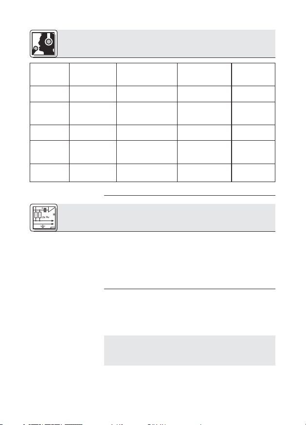
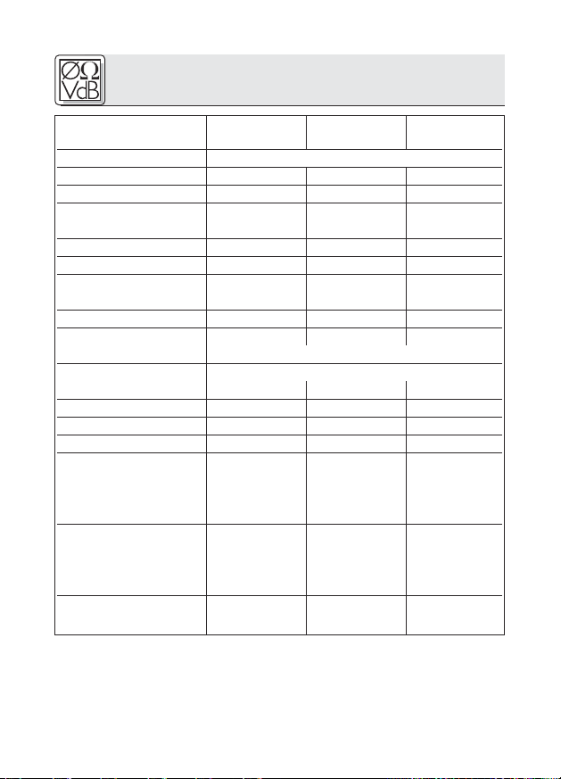
Siehe Tabelle 1.
3
3 Mikrofonanwendungen
Mikrofon
CGN 321 E
CGN 323 E
CGN 521 E
CGN 523 E
CHM 21
Tabelle 1: Mikrofonanwendungen
Richtcharakteristik
Niere
Hyperniere
Niere
Hyperniere
Niere
Lautsprecherposition
nur hinter dem
Mikrofon
seitlich bis schräg
hinter dem Mikrofon
nur hinter dem
Mikrofon
seitlich bis schräg
hinter dem Mikrofon
nur hinter dem
Mikrofon
4 Montage und Anschluss
4.1 Einleitung
4.2 Schwanenhalsmikrofone CGN .. E
Siehe Fig. 9 und 12.
Hinweis:
Siehe Fig. 10 und 11.
4
Alle Mikrofone der Discreet Acoustics Compact Serie
sind Kondensatormikrofone und benötigen daher eine
Stromversorgung (Phantomspeisung). Die Mikrofone
sind für den Anschluss an Mikrofoneingänge mit
Phantomspeisung (9 bis 52 V) ausgelegt. Anschluss an
Eingänge ohne Phantomspeisung siehe Kapitel 4.4.
1. Montieren Sie das Mikrofon mittels des optionalen
Montagesockels PS 3 F-Lock auf einer Tischplatte
oder mit dem optionalen Stativanschluss SA 60 auf
einem Boden- oder Tischstativ.
Zur besseren Körperschallunterdrückung können Sie
das Mikrofon auch mittels der optionalen elastischen
Lagerung H 500 oder H 600 in die Tischplatte
einbauen.
2. Schließen Sie das Mikrofon mittels eines geschirmten
Kabels an einen Mikrofoneingang mit
Phantomspeisung an.
Besprechungsabstand
30 - 60 cm
30 - 90 cm
30 - 60 cm
30 - 90 cm
1 - 3 m
Anwendung
Beschallung
Beschallung
Beschallung
Beschallung
Beschallung

4 Montage und Anschluss
3. Wenn die Phantomspeisung Ihres Mischpults
schaltbar ist, schalten Sie sie ein. (Lesen Sie dazu die
Bedienungsanleitung Ihres Mischpults nach.)
Das Mikrofon erhält seine Versorgungsspannung
direkt aus der Phantomspeisung.
1. Streifen Sie vor der Montage das Kabel leicht mit
der Hand aus. Achten Sie darauf, das Kabel weder zu
knicken noch zu verdrehen.
2. Bringen Sie an der Decke einen geeigneten Haken an,
bzw. spannen Sie eine Leine quer durch den Raum.
3. Legen Sie das Kabel so über den Haken, bzw. die
Leine, dass das Mikrofon in der gewünschten Höhe
hängt.
4. Fixieren Sie das Kabel mit Isolierband.
Befestigen Sie das Kabel auf keinen Fall mit
einem Knoten am Haken! Dadurch würde sich das
Kabel mit der Zeit verdrehen und das Mikrofon wäre in
der Folge nicht mehr positionierbar.
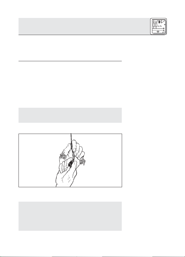
5. Halten Sie das Kabel mit einer Hand fest und drehen
Sie das Mikrofon vorsichtig in die gewünschte
Position.
• Das Kabel des CHM 21 verdreht sich bei
Temperaturschwankungen, z.B. durch die Wärme
von Scheinwerfern.
• Der Verdrehungswinkel hängt sowohl von der
4.3 Hängemikrofon
CHM 21
Wichtig!
Fig. 1: Ausrichten des
Mikrofons
Siehe Fig. 1.
Hinweis:
5
4 Montage und Anschluss
4.3.1 Mikrofon
stabilisieren
4.3.2 Anwendungshinweise
Umgebungstemperatur als auch von der Länge des
Kabels ab. Je kürzer das Kabel, umso geringer die
Verdrehung.
• Wenn Sie mit Scheinwerfern arbeiten, schalten
Sie diese ein, bevor Sie das Mikrofon ausrichten.
• Nach dem Ausschalten der Scheinwerfer wird sich
das Mikrofon verdrehen. Wenn Sie die Scheinwerfer
wieder einschalten, dreht sich das Mikrofon in die
selbe Position zurück, die Sie vorher eingestellt
haben.
Um die Mikrofonposition zu stabilisieren,
1. Fädeln Sie eine Angelschnur (durchsichtige
Nylonleine) entsprechender Länge durch die Öse an
der Federklemme des CHM 21.
2. Befestigen Sie die Angelschnur so an zwei
gegenüberliegenden Wänden, dass die Angelschnur
gerade genug Zug nach unten ausübt, um das
Mikrofon seitlich zu fixieren.
6
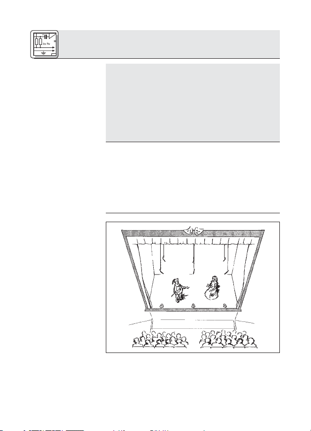
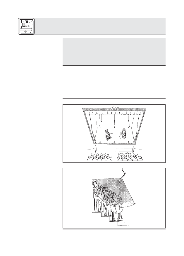
Fig.2: Theater-
beschallung
4 Montage und Anschluss
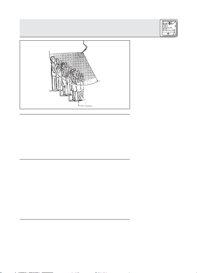
Fig. 3: Chorabnahme
1. Schließen Sie das Mikrofon mittels eines geschirmten
Kabels an einen Mikrofoneingang mit
Phantomspeisung an.
2. Wenn die Phantomspeisung Ihres Mischpults
schaltbar ist, schalten Sie sie ein. (Lesen Sie dazu die
Bedienungsanleitung Ihres Mischpults nach.)
Das Mikrofon erhält seine Versorgungsspannung
direkt aus der Phantomspeisung.
Wenn Ihr Mischpult keine Phantomspeisung besitzt,
schalten Sie ein Phantomspeisegerät zwischen Mikrofoneingang und Phantomspeiseadapter DPA. Wir
empfehlen die optionalen AKG-Speisegeräte B 18,
N 62 E und N 66 E.
Es ist aber auch möglich, symmetrische und
asymmetrische Mikrofoneingänge mit Phantomspeisung
nach DIN 45596 durch einen qualifizierten Techniker
nachrüsten zu lassen. Diese Norm schreibt eine positive
Spannung von 12, 24 oder 48 Volt an den NF-Leitungen
gegen die Kabelabschirmung vor.
4.3.3 AudioAnschluss
4.4 Stromversorgung bei
Eingängen ohne
Phantomspeisung
7
4 Montage und Anschluss
Symmetrische
4.4.1
Eingänge
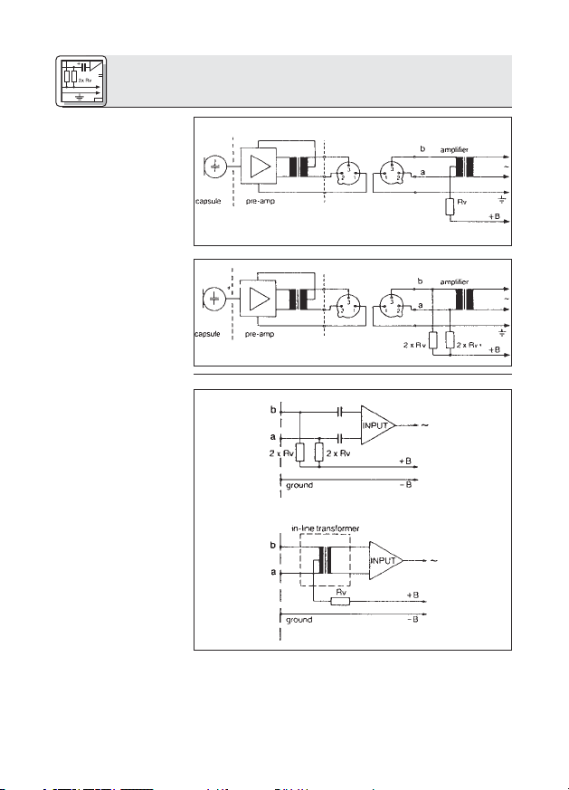
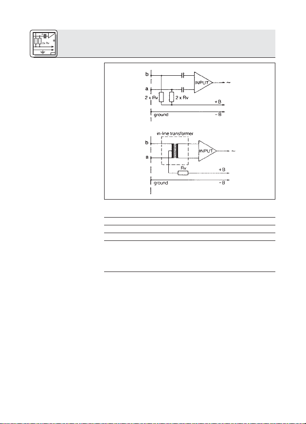
Fig. 4: Schaltung mit
Eingangsübertrager
mit Mitten-
anzapfung (erdfrei)
Fig. 5: Schaltung mit
Eingangsübertrager
ohne Mitten-
anzapfung (erdfrei)
4.4.2
Asymmetrische
Eingänge
Fig. 6: Asymmetri-
sche Eingangsstufe
8
Sind die Mischpulteingänge geerdet oder keine
Eingangsübertrager vorhanden, müssen Sie entweder
Kondensatoren oder zusätzliche Transformatoren in die
NF-Leitungen einfügen, um eine Beeinträchtigung der
Eingangsstufe durch Leckströme zu verhindern.
4 Montage und Anschluss
U= Rv 2 x Rv*
12V ±2V 330 Ω 680 Ω
24V ±2V 680 Ω 1200 Ω
48V ±4V 3300 Ω 6800 Ω
* Die Widerstände 2xRv dürfen aus Gründen der
Symmetrie max. 0,5% Toleranz aufweisen.
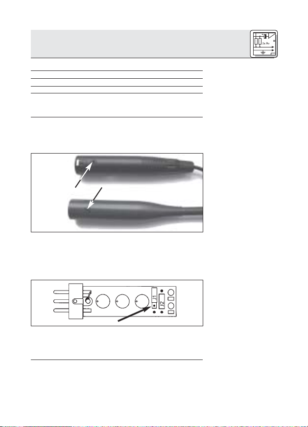
Der Phantomspeiseadapter DPA ist mit einer Bassabschwächung zur Unterdrückung tieffrequenter
Störgeräusche ausgestattet.
CHM 21
CGN ... E
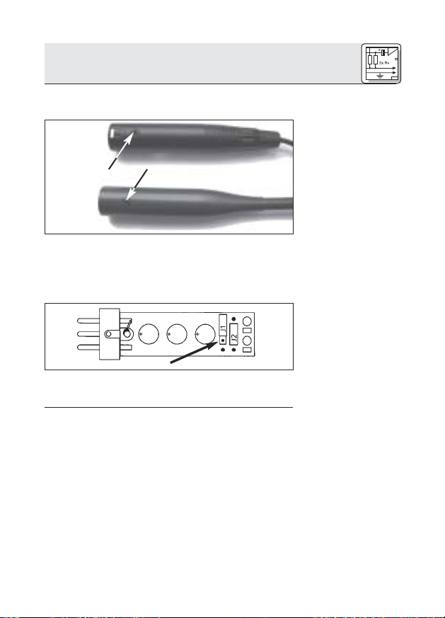
1. Lösen Sie die Befestigungsschraube am Mikrofon
bzw. Phantomspeiseadapter DPA.
2. Ziehen Sie den Print VORSICHTIG aus dem Gehäuse
heraus.
3. Zum Aktivieren der Bassabschwächung stecken Sie
die Drahtbrücke J1 in das mittlere Kontaktpaar am
Print ein.
Tabelle 2: Normwerte
für Rv (bzw. 2xRv)
4.5 Bassabschwächung
Fig. 7: Befestigungsschraube
Siehe Fig. 7.
Fig. 8: Print DPA
Siehe Fig. 8.
9
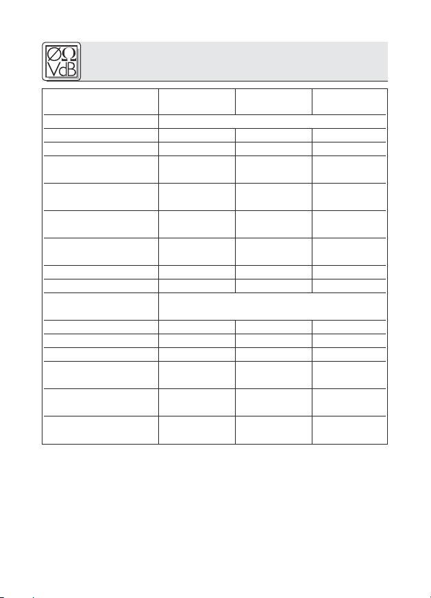
5 Technische Daten
Mikrofon CGN 321 E CGN 323 E
CGN 521 E CGN 523 E CHM 21
Arbeitsweise Kondensatormikrofon mit Permanentladung
Richtcharakteristik Niere Hyperniere Niere
Übertragungsbereich 70-18.000 Hz 50-19.000 Hz 70-18.000 Hz
Empfindlichkeit 18 mV/Pa 12 mV/Pa 18 mV/Pa
Ⳏ -35 dBV* Ⳏ -38 dBV* Ⳏ -35 dBV*
Grenzschalldruckpegel
(k = 1%) 125 dB 125 dB 125 dB
Äquivalentschalldruckpegel <21 dB-A <21 dB-A <21 dB-A
Signal/Rauschabstand
(A-bew.) >73 dB >73 dB >73 dB
Elektrische Impedanz <600 Ω <600 Ω <600 Ω
Empfohlene Lastimpedanz
Stromversorgung 9-52 V Phantomspeisung nach DIN 45596
Stromaufnahme <3 mA <3 mA <3 mA
Anschlussstecker XLR-3 XLR-3 XLR-3
Oberfläche dunkelgrau matt dunkelgrau matt dunkelgrau matt
Abmessungen 13,5 x 380 mm 13,5 x 380 mm
(Kapseldurchmesser x l) 13,5 x 580 mm 13,5 x 580 mm 13,5 x 55 mm
Netto-/Bruttogewicht 160/480 g 160/480 g
Bestellnummer 2965Z0001 2965Z0002
* bezogen auf 1 V/Pa
Dieses Produkt entspricht der Norm EN 50082-1, vorausgesetzt, dass die nachgeschalteten Audio-/Speisegeräte CE-konform sind.
>2000 Ω >2000 Ω >2000 Ω
(Adapter DPA integriert)
170/500 g 170/500 g 20/480 g
2965Z0003 2965Z0004 2965Z0005
10
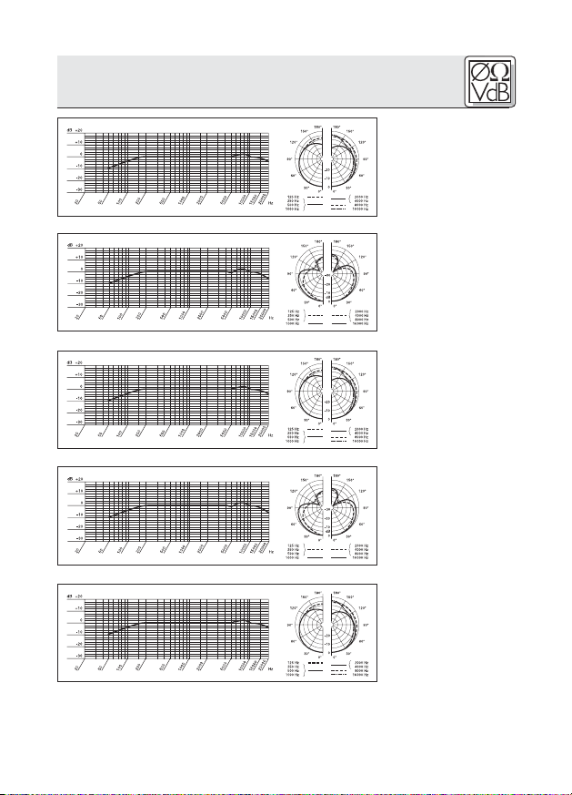
5 Technische Daten
Frequenzgang &
Polardiagramm
CGN 321 E
Frequenzgang &
Polardiagramm
CGN 323 E
Frequenzgang &
Polardiagramm
CGN 521 E
Frequenzgang &
Polardiagramm
CGN 523 E
Frequenzgang &
Polardiagramm
CHM 21
11

1 Safety and Environment
1. Do not spill any liquids on the equipment and do not
drop any objects through the ventilation slots in the
equipment.
2. Do not place the equipment near heat sources such
as radiators, heating ducts, or amplifiers, etc. and do
not expose it to direct sunlight, excessive dust, moisture, rain, mechanical vibrations, or shock.
3. The packaging of the equipment is recyclabe. To dispose of the packaging, make sure to use a collection/recycling system provided for that purpose and
observe local legislation relating to waste disposal
and recycling.
2 Description
2.1 Introduction
2.2 Microphones
Refer to figs. 9 to 14.
12
Thank you for purchasing a Discreet Acoustics
module. The Discreet Acoustics Compact Series comprises four gooseneck microphones, one flown microphone, and dedicated accessories for every application
and every type of venue.
CGN 321 E (order no. 2965Z0001): 380-mm (15-in.) cardioid gooseneck microphone with integrated DPA XLR
phantom power adapter and external foam windscreen.
CGN 323 E (order no. 2965Z0002): 380-mm (15-in.)
hypercardioid gooseneck microphone with integrated
DPA XLR phantom power adapter and external foam
windscreen.
CGN 521 E (order no. 2965Z0003): 576-mm (23-in.) cardioid gooseneck microphone with integrated DPA XLR
phantom power adapter and external foam windscreen.
CGN 323 E (order no. 2965Z0004): 576-mm (23-in.)
hypercardioid gooseneck microphone with integrated
DPA XLR phantom power adapter and external foam
windscreen.
CHM 21 (order no. 2965Z0005): cardioid flown microphone with spring clamp and 10-m (33-ft.) special cable
with DPA XLR phantom power adapter.
2 Description
Always use the supplied windscreen (unless it would be
too visually obtrusive). It protects the microphone from
dust and moisture, and reduces pop and wind noise to a
minimum.
B 18 battery power supply for all Discreet Acoustics
Compact microphones.
N 62 E, N 66 E AC power supplies for all Discreet
Acoustics Compact microphones.
PS3 F-Lock panel mount socket for all Discreet
Acoustics Compact gooseneck microphones (not for
CHM 21).
H 500 shock mount for all Discreet Acoustics Compact
gooseneck microphones (not for CHM 21).
H 600 shock mount for all Discreet Acoustics Compact
gooseneck microphones (not for CHM 21).
SA 60 stand adapter for all Discreet Acoustics Compact
gooseneck microphones (not for CHM 21).
ST 1, ST 45 table stands for all Discreet Acoustics
Compact gooseneck microphones (not for CHM 21).
3 Microphone Applications
Note that both the maximum working distance and the
area covered by the microphone depend on the pickup
angle. The smaller the pickup angle (hypercardioid), the
longer the maximum distance between the talker and the
microphone and the smaller the area covered by the
microphone.
Whether a cardioid or hypercardioid capsule will give the
best results therefore depends on the specific application
situation).
2.3 Windscreen
(2965Z2001)
2.4 Optional
Accessories
Refer to fig. 9.
Refer to fig.10.
Refer to fig.11.
Refer to fig.12.
Refer to fig.13.
Refer to Table 1.
13
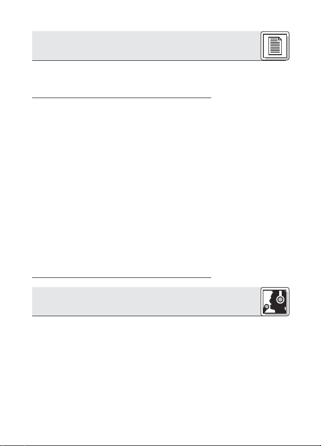
3 Microphone Applications
Microphone
CGN 321 E
CGN 323 E
CGN 521 E
CGN 523 E
CHM 21
Table 1: Microphone applications.
Polar Pattern
Cardioid
Hypercardioid
Cardioid
Hypercardioid
Cardioid
Speaker position
Beinde the microphone only
90° to 135° off
microphone axis
Behind the microphone only
90° to 135° off
microphone
axis
Behind the microphone only
* Depending upon Acoustic environment
4 Installation and Connection
4.1 Introduction
4.2 CGN .. E
Gooseneck
Microphones
Refer to figs. 9 and 12.
Refer to figs. 10 and 11.
14
All Discreet Acoustics Compact microphones are condenser microphones and therefore require a power supply
(phantom power). The microphones have been designed
for connection to microphone inputs with 9 to
52 V phantom power. To connect Discreet Acoustics
Compact microphones to inputs without phantom power,
refer to Section 4.4.
1. Use the optional PS 3 F-Lock panel mount socket to
install the microphone in a tabletop or an optional
SA 60 stand adapter to mount the microphone on a
floor or table stand.
Note:
For even better vibrational noise rejection, you can fix
the microphone to the tabletop with an optional H 500
or H 600 shock mount.
2. Use a shielded cable to connect the microphone to a
microphone input with phantom power.
Working
distance
30 to 60 cm*
(1 to 2 feet)
30 to 90 cm*
(1 to 3 feet)
30 to 60 cm*
(1 to 2 feet)
30 to 90 cm*
(1 to 3 feet)
1 to 3 m*
(3.5 to 10 feet)
Application
Sound system
Sound system
Sound system
Sound system
Sound system
4 Installation and Connection
3. If the phantom power on your mixing console is
switchable, switch the phantom power on. (Refer to
the instruction manual for your mixing console.)
The microphone is powered directly from the phantom power source on the console.
1. Prior to installing the microphone, straighten the
cable by carefully pulling it through your fingers. Make
sure not to buckle or twist the cable. Let hang for 1 day to
untwist.
2. Fasten a hook to the ceiling, use an existing hook, or
stretch a fishing line across the hall.
3. Pass the cable through the hook or over the line so
that it will hang at the desired height.
Do not tie a knot into the cable to hang it on the
hook. This may cause the cable to twist and misalign
the microphone after a while.
5. Hold the cable with one hand and turn the microphone carefully into the desired position.
• The cable on the CHM 21 will twist as the ambient
temperature changes, e.g., in the heat generated by
spotlights.
• The angle of twist depends both on the ambient temperature and the cable length. The shorter the cable,
the smaller the amount of twist.
4.3 CHM 21 Flown
Microphone
Important!
Fig. 1: Aligning the
microphone.
Refer to fig. 1.
Note:
15
4 Installation and Connection
• If you use spotlights, be sure to turn them on
before aligning the microphone.
• When you turn the spotlights off, the microphone will
rotate out of alignment. Upon turning the spotlights
back on, the microphone should rotate back into its
original position.
4.3.1 Stabilizing
the Microphone
4.3.2 Applications
To stabilize the microphone,
1. Leave an appropriate length of fishing line through the
eyelet on the spring clamp of the CHM 21.
2. Fix the fishing line to two opposite walls so as to create just enough downward pull to steady the microphone laterally.
Fig. 2: Theater stage
miking
Fig. 3: Miking up a
16
choir

4 Installation and Connection
1. Use a shielded balanced cable to connect the microphone to a microphone input with phantom power.
2. If the phantom power on your mixing console is
switchable, switch the phantom power on. (Refer to
the instruction manual for your mixing console.)
The microphone is powered directly from the phantom power source.
If your mixer has no phantom power, insert an external
phantom power supply between the DPA phantom power
adapter and mixer input. We recommend the optional
B 18, N 62 E, or N 66 E power supplies from AKG. Using
any power supplies not recommended by AKG may
damage your microphone and voids the warranty.
You may also consider having a qualified technician
retrofit a phantom power supply as per DIN 45596 to balanced or unbalanced mixer inputs. The DIN 45596 standard specifies a positive voltage of 12, 24, or 48 V on the
audio lines versus the cable shield.
If your equipment inputs are grounded or transformerless, wire either capacitors or extra transformers into the
audio lines as shown in fig. 9 above in order to prevent
any current leakage into the input stage.
4.3.3 Audio
Connection
4.4 Connecting to
Inputs without
Phantom Power
4.4.1 Balanced
Inputs
Fig. 4: Input transformer with center
tap (ungrounded)
Fig. 5: Input transformer with no
center tap
(ungrounded)
17
4 Installation and Connection
4.4.2 Unbalanced
Inputs
Fig. 6: Unbalanced
input stage
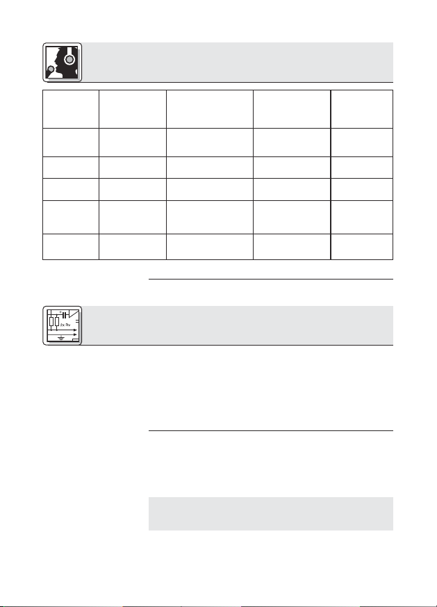
Table 2: Standard val-
ues for Rv and 2 x Rv
VDC Rv 2 x Rv*
12 V ±2 V 330 Ω 680 Ω
24 V ±4 V 680 Ω 1,200 Ω
48 V ±4 V 3,300 Ω 6,800 Ω
* In order to satisfy the DIN 45596 symmetry requirement,
make sure the actual values of the two resistors 2 x Rv
do not differ by more than 0.5%!
18
4 Installation and Connection
The DPA phantom power adapter is equipped with a bass
cut filter to minimize low-frequency noise.
CHM 21
CGN ... E
1. Unscrew the fixing screw on the microphone or DPA
phantom power adapter.
2. Pull the circuit board out of the case WITH CAUTION
– so as not to break the internal leads.
3. To acitvate the bass cut filter, plug the jumper J1 into
the central contact pair on the circuit board.
4.5 Bass Cut
Fig. 7: Fixing screw.
Refer to fig. 7.
Fig. 8: DPA circuit
board.
Refer to fig. 8.
19
5 Specifications
Microphone CGN 321 E CGN 323 E
CGN 521 E CGN 523 E CHM 21
Type Pre-polarized condenser microphone
Polar pattern Cardioid Hypercardioid Cardioid
Frequency range 70 to 18,000 Hz 50 to 19,000 Hz 70 to 18,000 Hz
Sensitivity 18 mV/Pa 12 mV/Pa 18 mV/Pa
Ⳏ -35 dBV* Ⳏ -38 dBV* Ⳏ -35 dBV*
Max. SPL for 1% THD 125 dB 125 dB 125 dB
Equivalent noise level <21 dB-A <21 dB-A <21 dB-A
Signal/noise ratio
(A-weighted.) >73 dB >73 dB >73 dB
Electrical impedance <600 Ω <600 Ω <600 Ω
Receommended
load impedance
Power requirement 9 to 52 V phantom power to DIN 45596
Current consumption <3 mA <3 mA <3 mA
Connector XLR-3 XLR-3 XLR-3
Finish matte dark gray matte dark gray matte dark gray
Size 13.5 x 380 mm 13.5 x 380 mm
(capsule dia. x length) (0.5 x 15 in.) (0.5 x 15 in.)
Net/shipping weight 160/480 g 160/480 g
Order no. 2965Z0001 2965Z0002
>2000 Ω >2000 Ω >2000 Ω
(DPA adapter integrated)
13.5 x 580 mm 13.5 x 580 mm 13.5 x 55 mm
(0.5 x 23 in.) (0.5 x 23 in.) (0.5 x 2.1 in.)
(5.7/17 oz.) (5.7/17 oz.)
170/500 g 170/500 g 20/480 g
(6/17.7 oz.) (6/17.7 oz.) (0.7 x 17 oz.)
2965Z0003 2965Z0004 2965Z0005
* re 1 V/Pa
This product conforms to EN 540082-1 provided it is connected to audio/power
supply equipment with a CE mark.
20
 Loading...