

Page 1

Plasma Display
Service Manual
PDP4247
E-Mail: customercare@akausa.com
Technical Support
800-726-4405
Page 2

Contents
Page
1. Important Information 1
2. General Information 2
3. Safety Precautions 3
4. Specification 4
5.Peripheral Equipment Connecting 5
6. Circuit Description 6~7
7. C
. BLOCK DIAGRAM 8
. AC FILTER 9
. VIDEO DISPLAY BOARD 10
. DC POWER BOARD 11
. ASSEMBLY DRAWING 12
8. Trouble Shooting Flow Chart
. ASSEMBLY CHART 13
. SET TEST CHART 14
. VIDEO DISPLAY CHART 15
9. Trouble Shooting Handy Tips 16
HAPTER BLOCK DIAGRAM & SCHEMATIC
Page 3
Impor tant Information
WARNING
SHOCK ! DANGEROUS !
DO NOT OPEN REAR COVER
WARNING:
1.This is a Class A and Class B product. In a domestic
environment this product may cause radio interference in
which case the user may be required to take adequate
measures.
2. TO REDUCE THE RISK OF FIRE AND ELECTRIC
SHOCK, DO NOT EXPOSE THIS PRODUCT TO RAIN OR
MOISTURE..
This lightning flash with arrow head s ymbol, within an
equilateral triangle, is intended to alert the user to the presence
of uninsulated "dangerous voltage" within the product's
enclosure that may be of sufficient magnitude to constitute a
risk of electric shock to persons.
The exclamation point within an equilateral triangle is intended
to alert the user to the presence of important operating and
ma int en anc e (s erv ic ing ) in str uctio ns in t he l ite ratur e
ccompanying the appliance.
1
Page 4
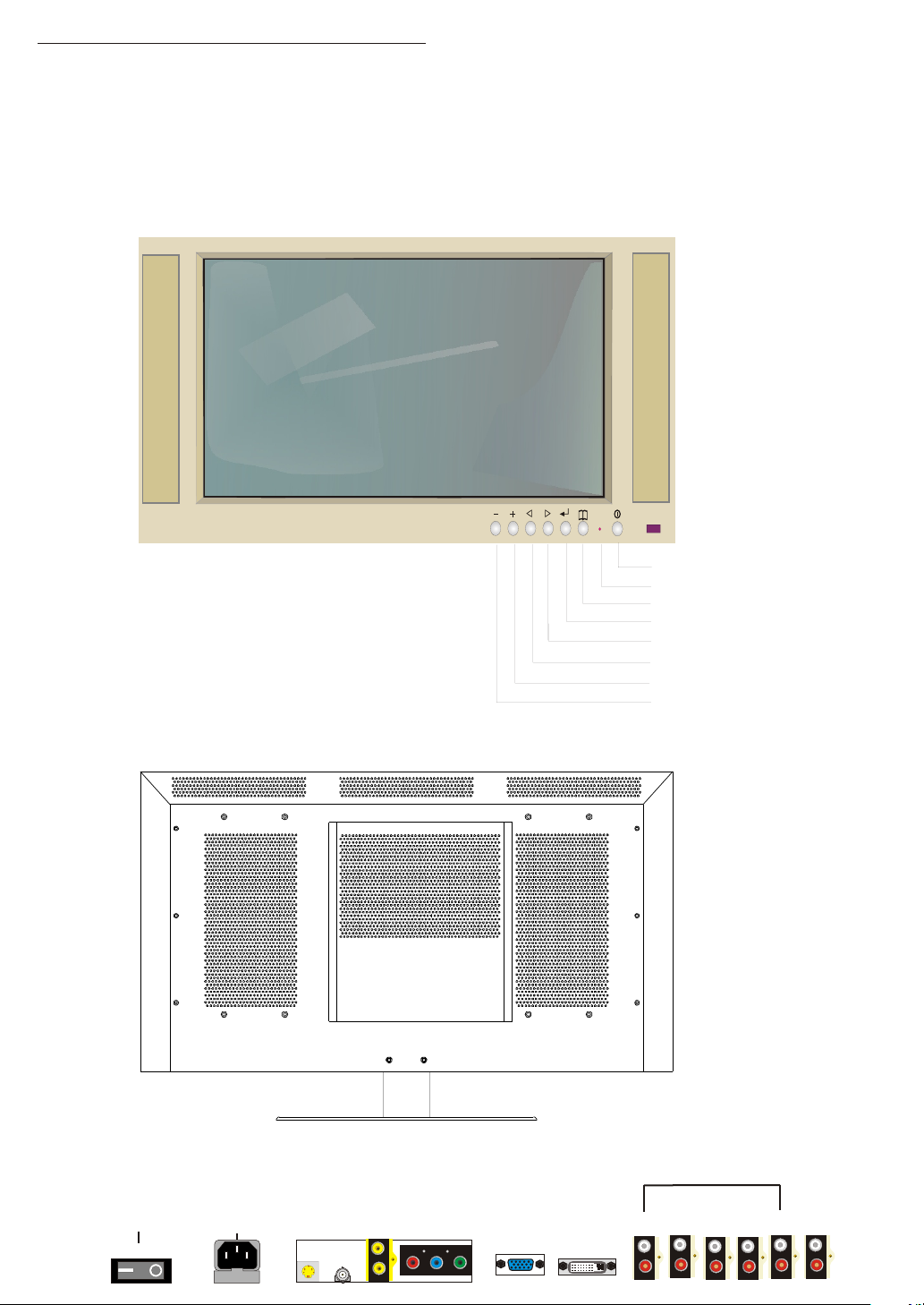
General Information
IMPORTANT:
Front View
Rear View
Power
LED
MENU
ENTER
UP
DOWN
+
_
POWER SWITCH
ON OFF
AC 90 ~ 240 V
INPUT
FUS EFUS E
S-VI DEO
INPU T
AUDI O
INPU T
AV2
AV1
AV1
AV3
Pr Pb Y
2
ANAL OG VGA
INPU T
DVI
INPU T
AV2
AV1
1
2 3
S-VI DEO
AV3
INPU T
4 5
COMP ONENT
AUDI O
OUTP UT
Page 5

Safety Precautions
Please read the following directions carefully before using the machine.
. Read each direction carefully, and retain for future reference.
. Please keep the manual well.
. Please follow the information to operate this machine.
. Clean the machine with a slightly damp soft cloth. Do not use spray
detergent and abrasive solvent. It can damage the machine screen coating
layer.
. Place the machine on a solid base to avoid dropping and danger.
. For good ventilation of the machine, please do not place the machine on
surfaces such as bed, sofa or rug.
. Before operating the machine, make sure that the operating voltage of your
machine is identical with that of your local power supply, if there is any
unclear, please contact with sales dealer.
. Use only the accessory power cord designed for this product to prevent
shock.
. Do not put anything under the power cord to avoid tramping.
. If using the same power source with other equipments, please make sure
the total current does not over 15A.
. Never attempt to repair a defection of the machine by yourself. Always
consult a skilled machine service personnel.
. When the following situations happen, please contact the qualified engineer:
A. The power cord or the power socket has damaged.
B. If any liquid or solid object fall into the machine through the ventilation
holes.
C. Exposing the machine to rain or excessive moisture.
D. The function does not follow the user manual.
E. The machine has ever been dropped or the glass has been broken.
F. The function of machine has clear changes.
. The plasma panel has been built using extremely precise and sophisticated
technologies; More than 99.99% of its pixels are effective. A minute
number of pixels are missing or constantly lit.
. Do not display the same picture (pattern) for a long period of time (Do not
exceed 20 min). This may cause images remain.
. No further notice will be provided if the specification and design subjects
have been changed.
. Release the battery of remote controller after long-time replacement (over 1
month) and avoid making destruction of remote controller by liquid.
.
.
3
Page 6
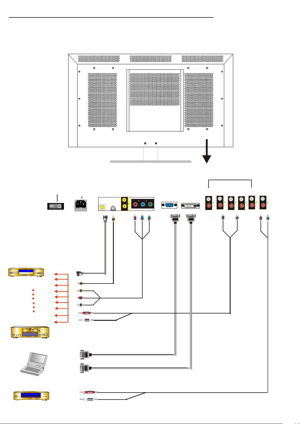
Peripheral Equipment Connecting
AUDI O
INPU T
DVD Pla yer
VHS Pla yer
Compu ter
POWER SWITCH
ON OFF
AC 90 ~ 240 V
INPUT
FUS EFUS E
S-VI DEO
DVD S -Vide o Out put
DVD I mage Ou tput
AV1
AV1
INPU T
DVD YPbPr O utput
Ana logue P C Outpu t
AV2
Pr Pb Y
AV3
DVD Au dio Out put
ANAL OG VGA
INPU T
DVI
INPU T
AV1
AV2
2 3 4 5
1
COMP ONENT
AUDI O
OUTP UT
S-VI DEO
AV3
INPU T
Ampli fier
Dig ital PC O utput
Aud io Inpu t
5
Page 7
CIRCUIT DESCRIPTION
1. DC POWER SUPPLY
This is the direct current output power supply within the PDP.
Its 5V and 12V direct current is output from CN1 that joins the
alternating current and via pass-band inductance(L1),
Bridge rectifier(BDI) IC, Converter(T1), D3, D4, and Cn2.
AC range is from 90V to 264V and the Frequency range is from
50Hz to 60Hz. Max. Power Consumption is 40W.
AC INPUT
EMI FILTER
RECTIFIER
AND
SMOOTH
PWM
CONTROL
HIGH FRG
CONVERTER
RECTIFIER
SMOOTH
6
Page 8

2. VIDEO DISPLAY BOARD
This is the Video/Audio Processing Device in the PDP.
1. It is compatible with R.G.B.H.V. Analogue Signal, DVI Digital
Signal, AV Component Signal, and S-Video Composite Signal.
R.G.B.H.V Analogue Signal is converted to Digital Signal by
U4 via the input transferring of (15 PIN) J1. The signal is then
transferred to U9 for Video signal output.
(DVI) J2 Signal is digitalized by U4 and then is transferred to
U9 for Video Signal Output.
AV Component Signal is input via J3. When the input signal
is SDTV, the signal is processed by U5 and is then transmit to
U7 for signal processing. After that, the signal is transmit to U9
for Video Signal Output.
When the Input signal is HDTV, the signal is digitalized from
Analogue by U4 and is then transmit to U9 for Video Output
Processing.
S-Video and AV Composite Signal is input by J4, J5, J6 to U5 for
Video Processing. The signal is then transmit to U7 for signal
processing and lastly is transmit to U9 for Video Output Processing.
2. Audio is input by J9 and J10 and the first stage processing is
made by U32. It is then transmit to U34 for last stage processing
and is amplified to the speakers for sound output.
3. Audio is output by J11. Sound input is transmit by J9 and J10 to
U32 for first stage processing and is then output by J11.
7
Page 9

µº¤¶¹ (CHAPTER BLOCK DIAGRAM & SCHEMATIC)
1. BLOCK DIAGRAM
Panel
FAN
DC
Power
Filter BD
Video BD
AC Filte r
8
Page 10
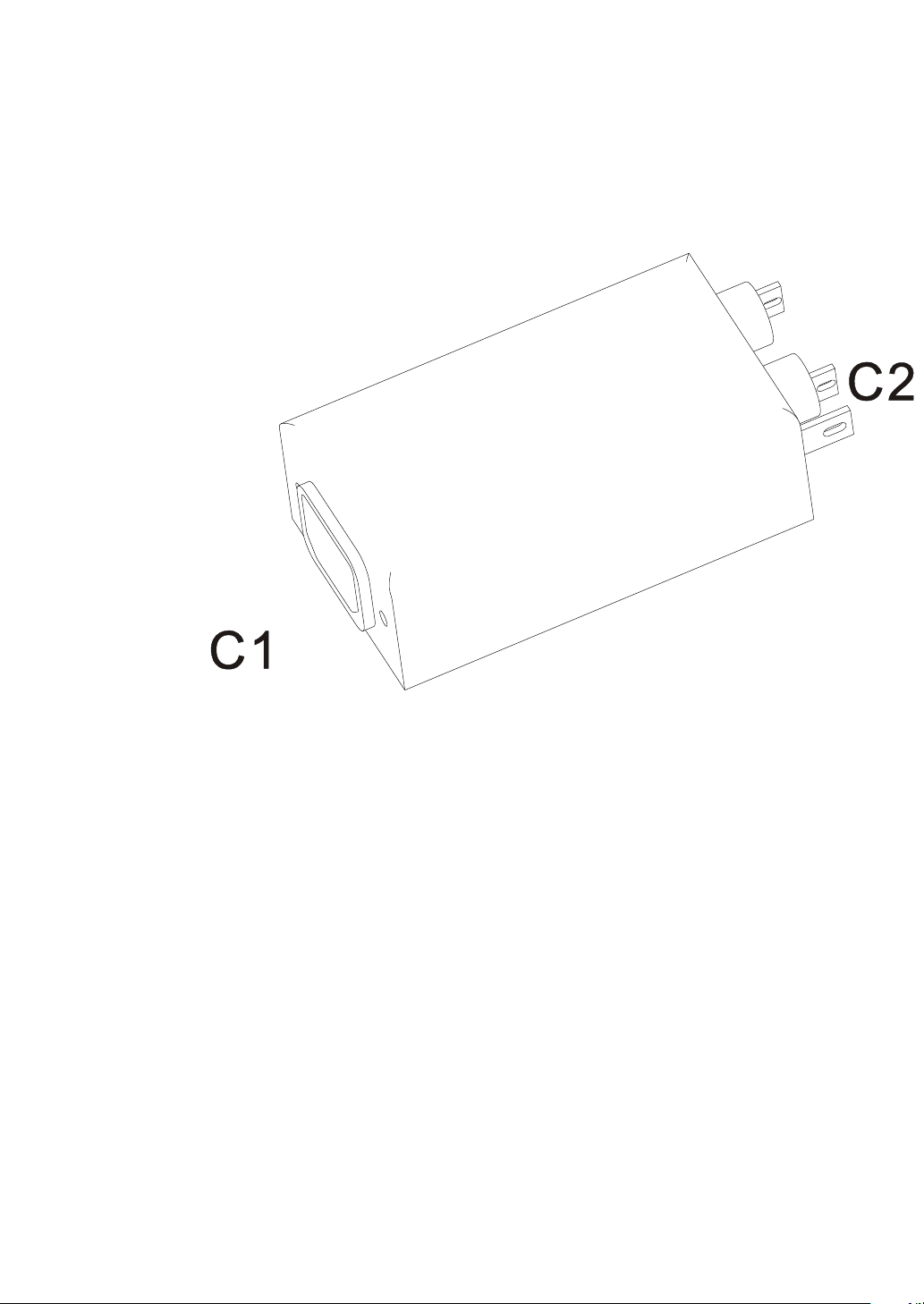
2. AC FILTER
1.AC INPUT TO C1
2.C2 TO PANEL & DC POWER Cn1
9
Page 11
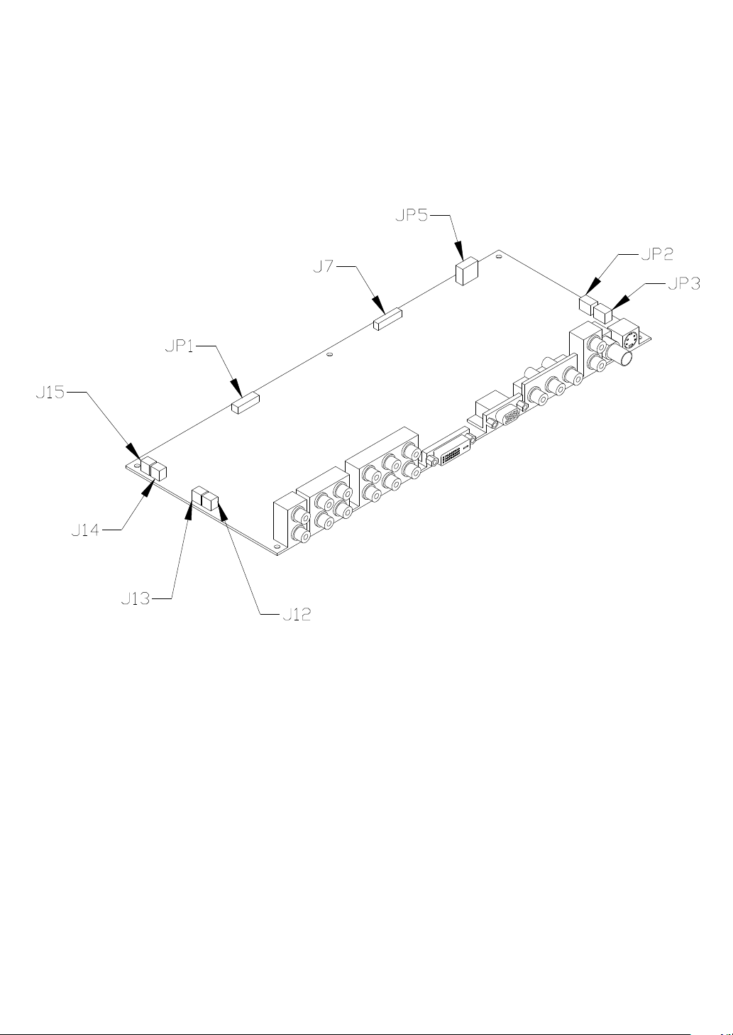
3. VIDEO DISPLAY BOARD
1.JP1 TO PANEL
2.JP2, JP3 TO FAN
3.JP5 TO DC POWER
4.J7 TO KEYPAD
5.JP12, JP13, JP14, JP15 TO SPEAKER
10
Page 12

4. DC POWER BOARD
2
CN
CN1
1: CN1 TO AC INPUT
2: CN2 TO VIDEO BOARD JP5
11
Page 13

5. ASSEMBLY DRAWING
1
2
4
5
6
7
8
9
10
3
11
12
13
1. FRONT COVER«®
2. FILTER GLASS Â¥¬¼
3. PLASMA PANEL ¹¼¼²
4. REAR PANEL ¤ª
VIDEO BOARD ¼¹½¸ª
5.
6. VIDEO PANEL ¥¯«¥ª
7. REAR COVER ¤-ª
8. DC POWER ª¬¹·¨À¾
9. AC SWITCH ¹·¶Ã
10. AC FILTER AC¹·Âª¾
11. STAND HOLDER ¸®©©ª
12. STAND ¶¬
13. STAND BOTTOM ©®
12
Page 14

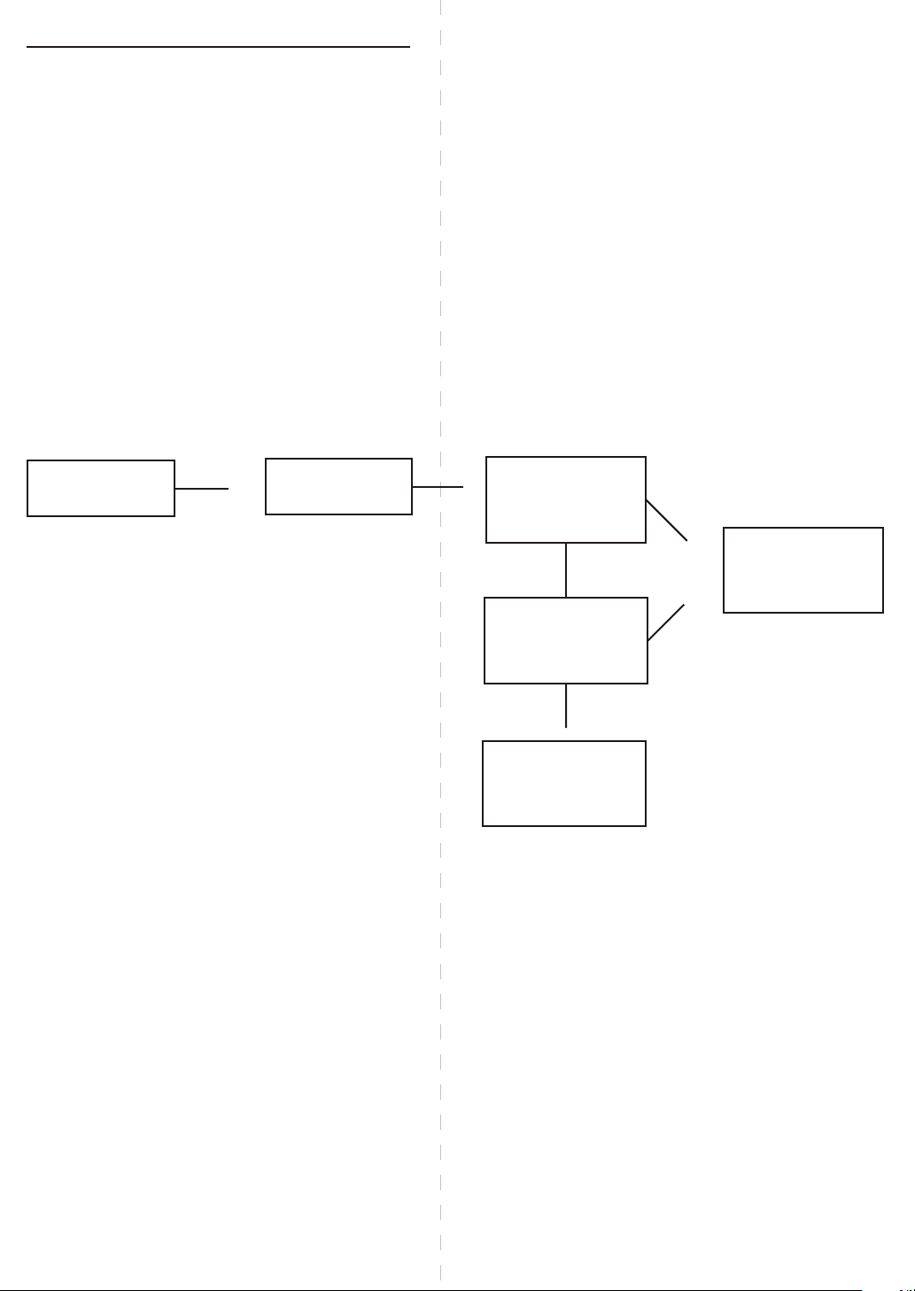
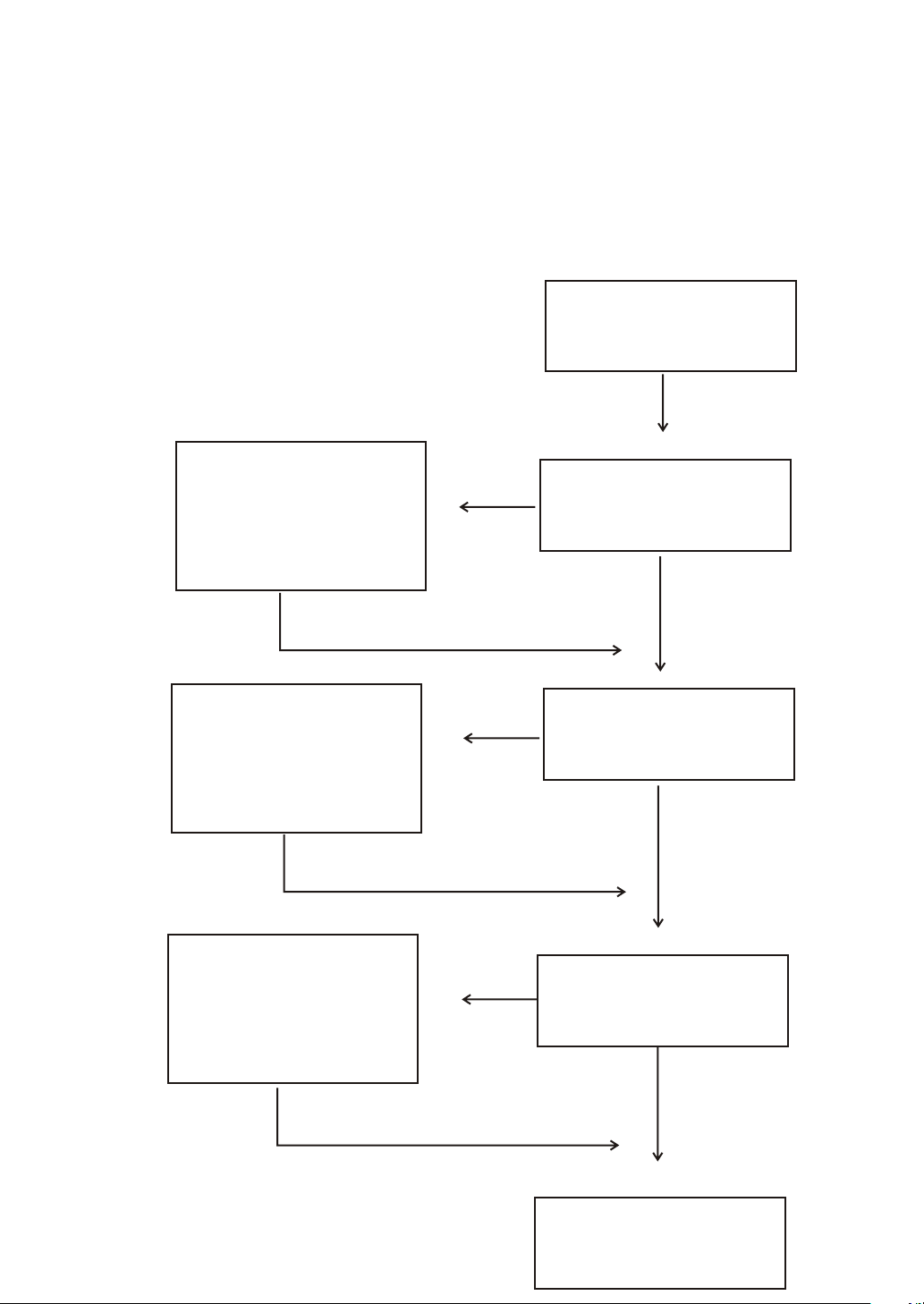
TROUBLE SHOOTING FLOW CHART
1. ASSEMBLY CHART
START
CHECK
I/O &
AC INPUT
CHECK
VIDEO BOARD
DC POWER
CHECK
AUDIO CIRCUIT
SPEAKER OUTPUT
NO
PANEL TEST
YES
NO
VIDEO TEST
YES
NO
AUDIO TEST
13
YES
END
Page 15
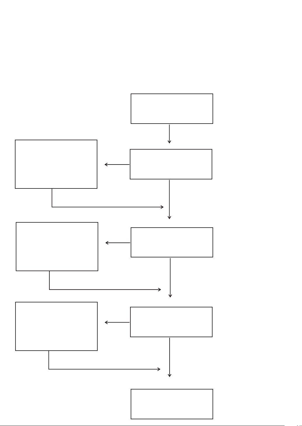
2. SET TEST CHART
CHECK
1. AC INPUT
NO
START
VIDEO DISPLAY
2. DC POWER
3. VIDEO BOARD
CHECK
1. SPEAKER
2. VIDEO BOARD
3. AUDIO CIRCUIT
FIX
WHITE PATTEN
TEST
NO
NO
I/P
YES
Audio Volume
I/P
YES
PANEL DISPLAY
14
YES
END
Page 16
3. VIDEO DISPLAY CHART
START
CHECK
SIGNAL
CABLE,U4
CHECK
SIGNAL
CABLE, U5 U7
CHECK
INPUT
NO
RGB I/O
DVI I/O
YES
NO
AV I/O
YES
NO
AUDIO I/O
CABLE, U32 U36
END
15
YES
Page 17
¬»À-
,.
¬»²¶
¨¦¼¹
椥±
µ¬°
µ¤·
¬»¦
1. ¹·½¸±¦?
2. ¥¹·Á¬§¥¶?
3. «¸½¬§±¦?
4. ¾¾¬§¦¬¹ªº?
1. 欧½¤²?
2. ¦¬¬§°±?
3. «¸½¬§±¦?
1. «¸½¬§±¦?
¿¤«¸¬§¶¥
2.
À²½³?
««¤¹¤±¨¬§
½¤¤?
¬»À
1. ±¹·½±¦
2. «¤¥¹·Á
3. ±«¸½±¦
4. «¹¸¤¥¦Á
1. ±Ã¦½¦¥±¦¸
2. ±¦¬½¦¥±¦¸
3. ±«¸½±¦
1. ±«¸½±¦
2. ½¾«¸À²¦¾
¥À²
±««¤¹¤½¾¦¥
±¦¸
µ¤¤©¤¤
¦Á¦¨¦¼¹
¦¼¹¦¨¦Á
»±¥¥§¥
若在螢幕右上角處出 現
"Fan Erron"或"Led" 呈現
紅色閃爍狀時
1. ¤¥±¨¬§¾·?
2. «ª±¨¬§¾·?
1. ¿¤·¤¦¬§¾·?
2. ¿¤·¬§¾·ª±
¦?
1. ¿¤·¬§¦°Ã?
2. ¶¬§½¦³¤?
3. Á°¸½¬§³±
¦?
1. »±¾¬§¹¤¤¨?
2. ºª,À¹©¹À¤Â?
¤³®¥²°Ã
16
1. ½¾¤¥±¨¤¤
2. ½¾«ª±¨¤¤
1. ½»¿¤·ª¤¦
2. ¥½¦±°¸½±¦
1. ½»¿¤·
2. ½¦¾·ª¶
3. ¥½¦±Á°¸½
±¦
1. §´·¹¦
2. ©¤¹·´À¬10¬
«¦´¤¹·À,·¶
¾§¥
½³ª·¦¦®¤
º¤
Page 18
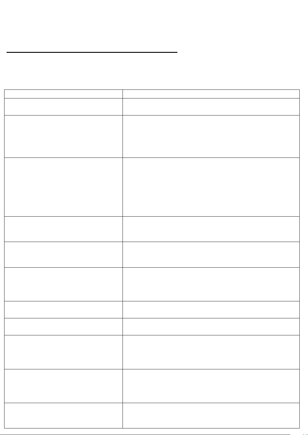
Cleaning And Maintenance Handy Tips
In the event of problems with the display, check the following explanations before
contacting your dealer for servicing.
Problem Action
Power does not turn ON. Check whether the power plug is securely inserted
into the receptacle.
No pictures are displayed. Check cables for disconnection.
Check whether the power for all input equipment in
ON
Check for connection to wrong terminals or for wrong
input mode.
Remote control does not function
properly.
Check for incorrect battery orientation.
Check for dead batteries.
Check for distance from the display.
Check whether you are pointing the remote control
transmitter properly at the display’s receiver.
Check for any obstacle between the remote control
and display.
The display makes a snapping
sound.
This sound is produced when the cabinet expands or
contract due to variations in temperature. This sound
does not indicated that the display has problem.
The display makes a buzzing
sound.
The display has fans to maintain the temperature of
internal components at a constant level. This sound
is produced by the fan as rotates.
There are spots on the screen. Check whether your AV equipment is affected by
interference from automobiles, trains, high-voltage
transmission lines, neon signs or other potential
sources of interference..
Degraded color/tints. Check Whether all picture adjustment have been
properly made.
Improper screen position/size. Check whether screen position and size have been
properly adjusted.
If “Out of range“ appears, the
display is receiving a signal whose
picture or signal cannot be
reproduced by the display.
Input proper signals.
Make sure that the vertical frequency of the input
signal is 85 Hz or less for SVGA, 75 Hz or less for
XVGA/SXGA, 60 Hz or less for UXGA.
The screen turns to black and
white.
Input proper signals.
Make sure that the vertical frequency of the input
signal is 85 Hz or less for SVGA, 75 Hz or less for
XVGA/SXGA, 60 Hz or less for UXGA.
If you see the “Fan Error“ at the
top of right-hand side of the screen
or the flash or red led.
Please call the local agency to change the fan.
 Loading...