

Page 1
LEA-19S02P
Page 2
17
20
21
22
Page 3
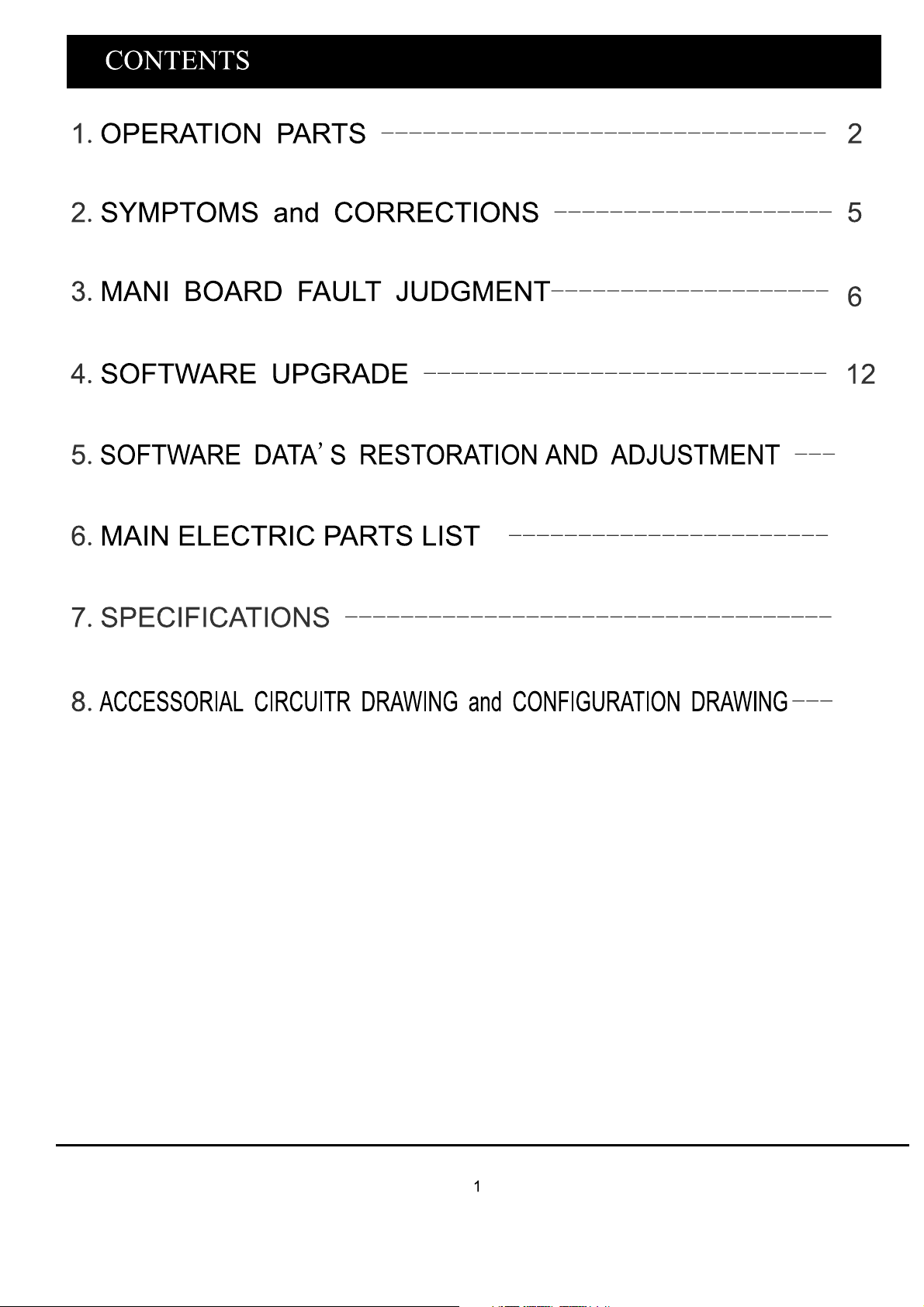
OPERATION PART S
Top View of TV Set:
Rear View of TV Set
TV/AV
MENU
VOL
VOL
CH
CH
ITEM
1
2
3
4
5
BUTTON NAME
MENU
TV/AV
-VOLUME+
-CH+
FUNCTION DESCRIPTION
Press to bring up the main menu to the
Press to select the input source.
Press to increase or decrease the
Press to scan through channels.to scan
Quickly channels,press and hold down
screen.
sound level.
Either +/- button.
Switch ON the LCD TV when at standby
Mode or vice versa
1.DC IN 12V
2.HDMI IN
3.VGA IN
4.PC Audio IN
5.SCART
6.HeadPhone OUT
7.Y IN
8.Pb/Cb IN
9.Pr/Cr IN
10.Video IN
11.Right channel Audio input
12.Left channel Audio input
13.RF IN
RF IN
13
L
12
11
R
V
10
IN
PR
9
PB
8
7
Y
DC12V
IN
1234
HDMI
IN
VGA
IN
PC AUDIO
IN
SCART
5
EARPHONE
OUT
6
2
Page 4
OPERATION PART S
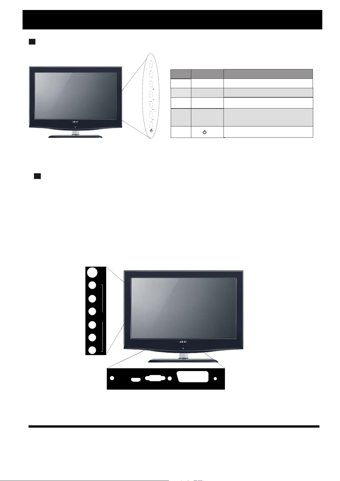
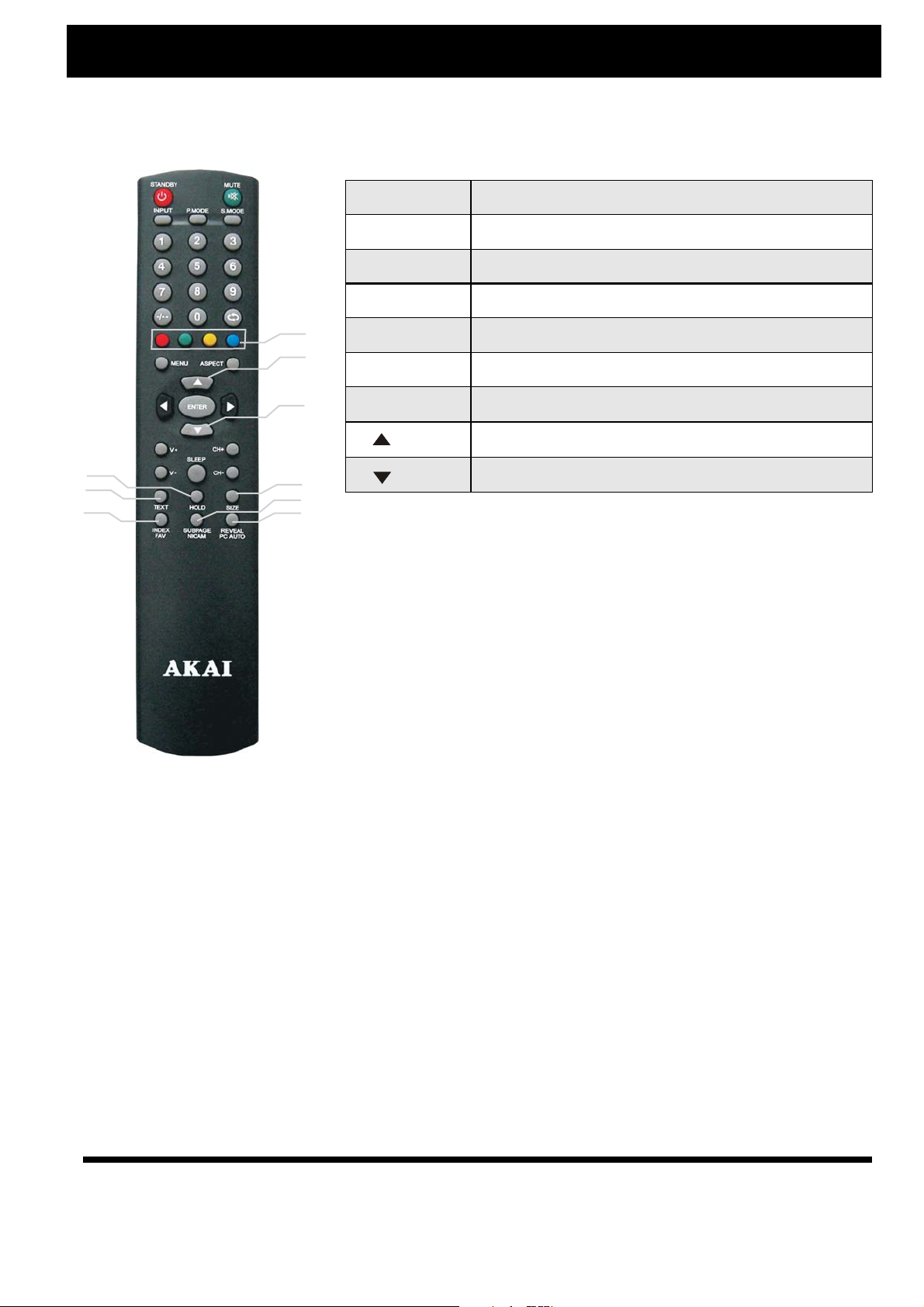
Remote Control
1
15
2
13
14
3
4
1.STANDBY
2.MUTE
3.0-9
4.SWAP
5.ASPECT
6
8
9
10
17
16
5
7
11
12
18
LCD MENU
6.
/
7.
8.ENTER
9.
/
10.VOL+ or VOL
11.
CH+ or CH-
12.SLEEP
13.PMODE
Press this button to switch on the TV when in standby mode or to enter
standby mode
Mute or restore sound
Number selection.
Press to return to the previously viewed program.
Press to select Picture Ratio.
Menu enter/exit.
UP/DOWN
Confirmation key
LEFT/RIGHT
Press these buttons to lower or raise the volume.
-
Press these buttons to select channels in ascending or
Descending order.
to
Press
Set
the Sleeper timer
turning off into standby.
for
Press to select different picture mode.
14.SMODE
15.INPUT
16.FAV
17.NICAM
18.PC AUTO
Press to select the different sound mode.
Press to cycle through the input source to select ATV,
HDMI,SCART,YPBPR,AV,VGA.
Press to select the favorite channels.
Multi-sound mode selection.
Press to do auto configuration directly for VGA Input.
3
Page 5
OPERATION PART S
TELETEXT OPERATIONS
1.TEXT
2.HOLD
3.SIZE
4.INDEX
7
8
9
2
1
4
3
5
6
5. SUBPAGE
6.REVEAL
7.COLOR
8.
9.
Switch on or off the teletext mode.
Hold on or off for current page display.
Change display size in teletext.
Request the index page.
Sub page.
Reveal the teletext information.
These keys are effective in teletext Signa,please follow the prompts.
Page up.
Page down
4
Page 6
SYMPTOMS and CORRECTIONS
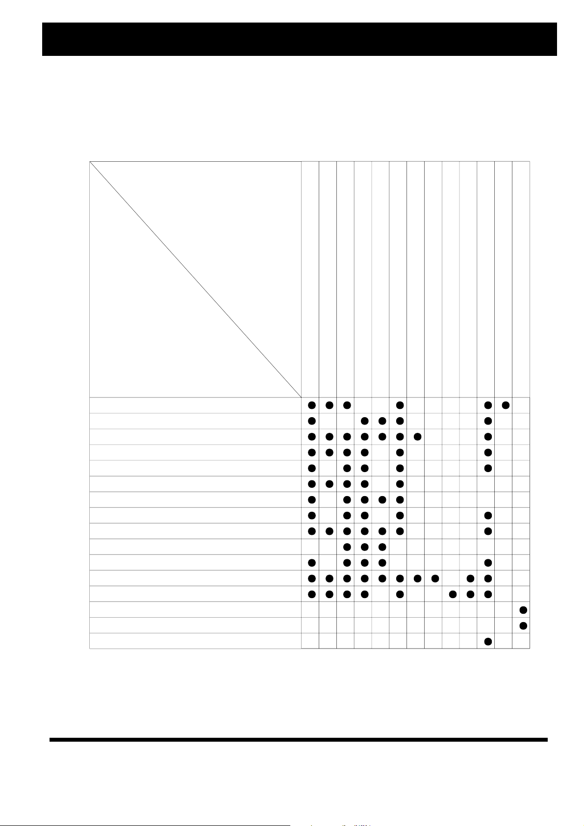
SYMPTOMS and CORRECTIONS for TV SET
Please make these simple checks as indicated (●) on the chart for the respective symptoms and their
possible remedies.
Possible Remedies
correctly set
Symptoms
No picture, no sound
Poor sound, picture OK
Poor picture, sound OK
Weak picture
Blurred picture
Double image
Lines in picture
Distorted picture
Weak reception on some channels
Horizontal bars
Picture rolls vertically
Poor colour
No colour
Misoperation of Remote control
Remote control unit no operation
On Screen Display Control outside the screen
Try different channel, if OK, probably station trouble
Check aerial connections on back of set
Check aerial for broken wires
Re-orient aerial (if indoor type)
Probably local interference, such as an appliance
Adjust fine tuning control
Adjust brightness control
Adjust contrast control
Check if station is broadcasting colour
Adjust colour control
Check if on/off switch is "on"
Check if system is
Check batteries in remote control unit
5
Page 7
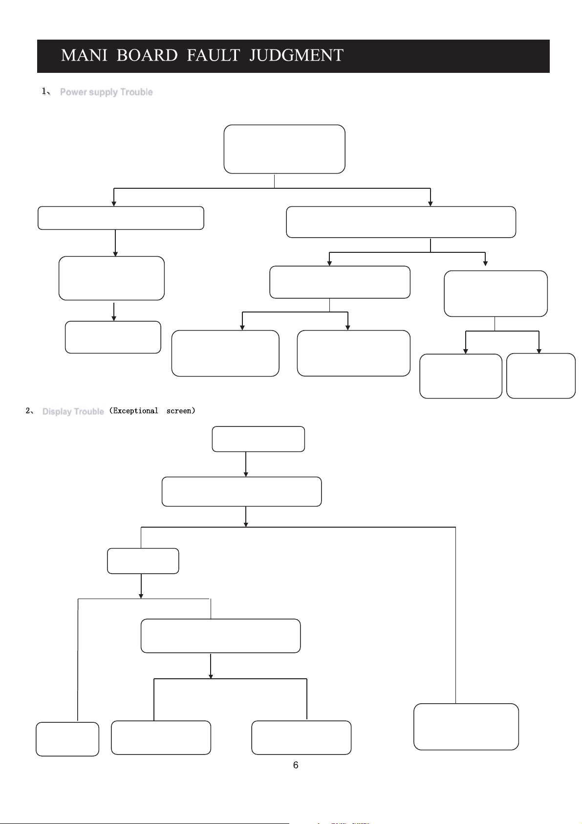
ǃ Power supply Trouble
&KHFN)$IRU9
1
&KHFN)XVH)DQGSHULSKHUDOSRZHU
VXSSO\
)XVHGHDGZKHQSRZHU
RQ"
<
&KHFNSRZHUVXSSO\
IROORZ)
H[WHUQDOFLUFXLWRU
ǃ Display Trouble ˄([FHSWLRQDOVFUHHQ˅
1
&KHFN8
FKDQJH8FKLS
Exceptional screen
<
SRZHURQDQGFKHFNLIYROWDJHRI(9LV
ZRUNDEOH
1
'RHVWKHSLQQRRI8WKH
ORDGLQVKRUWFLUFXLW
<
8KDVGDPDJHGRUWKH
ORDGLQVKRUWFLUFXLW
&KHFN5KDV
<
WKHRXWSXWYROWDJH
RI8LV9LV
QRUPDO
GDPDJHRU
FKDQJH8
<1
&KHFN8
FKLS
Change LCD
Check if the cable for panel is correct and
Connected tightly
Y N
Check if the
LCD panel is OK
NY
Check if the output circuit jack is
normal
Y
Check the circuit of U14 Repair the damage
circuit
N
Change the cable for
Panel connector
Page 8
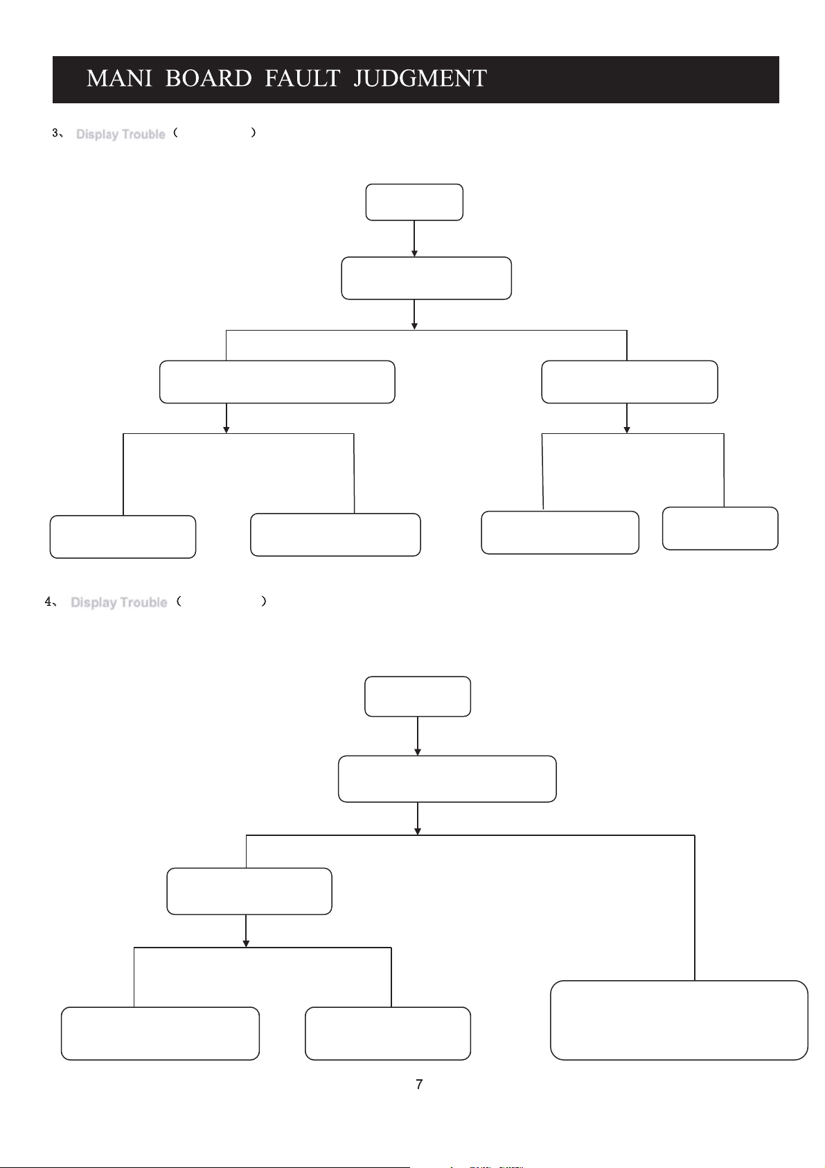
ǃ Display Trouble ˄white screen˅
White screen
Check the power supply for
panel
NY
Check the switch signal for Q8/AO3401’s
G-pole voltage (3.3V~0V or 5V~0)
Check CN17 or change
Q8
Check the circuit of U14 pins
Or if the I/O of U14 is damage
ǃ Display Trouble ˄black screen˅
NY
Change the LCD panel
Or the cable to panel
Black screen
The voltage of BLON Signal in
5V ? (on CN3)
Check the output signal of U14
Y
Change U14
N
Is inverter power is normal?
NY
Check and repair power supply
Y
N
Check the circuit from BLON pin to U14
Check if inverter power
or U14 I/O damage (pin 67)
Is damage
Page 9
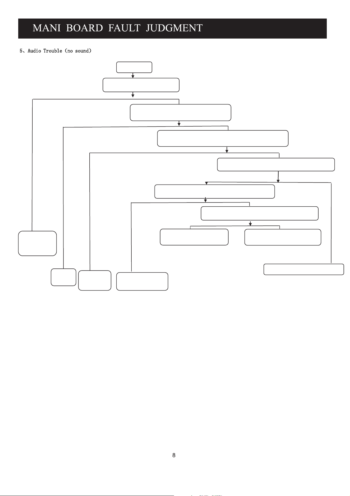
ǃ$XGLR7URXEOH˄QRVRXQG˅
N
No Sound
Check if have audio signal
input
Y
Check the set of volume, Mute is normal
Check external
Audio equipment
Rest it
N
Check external
Y
speaker
Does Q28 has damage
And repair D47 or R257
Y
Check signal output on pin no. 4 & 6 of U1
Is normal
Check power supply (>11V)on pin no. 7 of
Y
Check the voltage (>9.2V) on pin no.8
Of U21
Check the signal output on pin 50 &51 of U14
Does it has signal input on U14
N
U21/TDA1517P
N
YN
YN
Check the circuit from U14 to U21
Repair the U21 power supply
Page 10

ǃ)XQFWLRQ7URXEOH˄79YLGHR˅
N
TV cannot scan any channel/
picture
Check if the RF cable do have signael
Y
Check the pin no. 7 of T1 is 5V
Y
N
repair external RF equipment
ǃ)XQFWLRQ7URXEOH˄79D XGLR˅
Check the pin no. 8 of T1 has signal
Y
Check the network from pin no.8
of T1 to U14 /TSUMV26KE
or network between U14
and TV pins or 33v Boost Circuit
TV no sound but pictures
Check the pin no. 4 & 5 of T1 has date of
I
Y
N
Check pin no. 2 of T1 has voltage
(1.8 ~4.3V)
NY
T1 damage
Repair this circuit
2
C
Check I2C net
(Circuit from pin
no.68 to pin no.69 of
SUMV26KE or from
pin4 to pin5 of T1)
N
Repair this
pin power
net
N
Ref to the repair process of
“No. 5 – Audio trouble (no sound)
Is the same on PC ?
Y
Check the pin no. 1 & 2 of SAW1/AF389A2D has signal ?
YN
1. SAW1 damage
2. The circuit from SAW1 to U14 is not in normal
3. U14 damage
Check the network
from the pin no. 1&2 to the
tuner
Page 11

ǃFunction Trouble˄PC˅
8
Under PC channel
Picture is not in center
Do “Auto adust
“process
the DDC settings
color fade
Check the R.G.B input
signal for U14
YN
Reset
Check
R.G.B circuit
Image Stabilization
Check if VS,HS signal is
ruled and stable
YN
OSD settings do
not match,
reset the OSD or
input mode
not support
Check the circuit
of VS, HS
No signal
Check the circuit of VS, HS
Page 12

ǃFunction Trouble˄SCART , HDMI,S-VIDEO,CVBS˅
9
SCART RGB .SCART Video. HDMI,S-VIDEO,CVBS
HDMI,S-VIDEO
Have no signal
1. HDMI terminal pad
contact is badly
2 .System DDC settings
is wrong and reset it
3.U14 damage
Color fade
Check the input of R.G.B.
YN
System settings is wrong
and reset it
Of U14
Check the wire from CVBS
terminal to signal source
1.Check the R.G.B circuit
2.Check U14 or the circuit of U14
CVBS has no signal
Check the signal input
of CN9 is normal
N
Whether the pin no.18
of U14 has input?
YN
The soft of U14 is
not normal
Or U14 damage
Y
Check the circuit
between
U14
and CN9
Page 13

1. Hardware connection:
1.1 Connect the USB ISP tool to
of PC, then
USB
port
install
driver.
1.2 For board upgrade, Connect
the USB ISP tool and
of main board with 4pin
CN18
cable as
below
blue
picture.
1.3 For CBU upgrade, Connect
the
USB ISP tool to
board
with
4pin cable, then
plug the VGA
VGA
board to
main board.
Note: Please use the VGA
upg
rade method generally.
Please check carefully
the
connection of TXD
and RXD
board and
between upgrade
VGA board.
Page 14

2. Install software:
2.1 Advise to use English WINDOWS
XP OS, and please open the control
panel of WINDOWS,enter view
item of folder option,cancel
seleting hidden extension of
known file type.
2.2 copy folder ISP_TOOL_V
and folder USB_DRIVER to PC.
2.3 Install USB Driver from folder
USB_DRIVER.after installation
finish, please restart PC.
Note: after insert the USB ISP TOOL
to PC if USB DRIVER is accurate,
PC will be have a virtual port
...
COM .
3. Upgrade step:
3.1 Run the ISP_Tool.exe on your
computer as below picture.
3.2 Check the Config parameter as
below.
Page 15

3.3 Press “Read” to choose burning
file as below picture.
3.4 Open the burning file(*.bin).
3.5 Power on, press “Connect” to
connect the main board.
14
Page 16

3.5.1 If connect success, picture will
be as below.Press “OK” continue.
3.5.2 If connect fail, picture will be as
below. Press “OK” check.
3.5.2.1 Check tool connect and driver
install of USB ISP tool first.
3.5.2.2 Check the power connect and
power on.
3.5.2.3 Repress “Connect” retry
3.5.3 Press “Auto”, choose parameter
as below picture.
15
Page 17

3.5.3.1 Burning, Please wait
3.5.3.2 Burn finished. Pease power
of
,then take out the power
plug and USB ISP Tool plug
3.6 If burn fail, please retry again from 3.5 step.
Warning:Don’t disconnection the
power while upgrading!
Note:please restore the data after
upgraded
16
Page 18

Setting item.
Select Reset item,then press RIGHT
Select RESET EEPROM item,press RIGHT
button to do reset EEPROM.
3.2.Select this item,you may adjust the inner data,
as follow:
ADC ADJ for VGA:step1,step2(AUTO ADJ)
RESET EEPROM(restore inner data)1,2,3:
17
Page 19

3.2.3.Picture settings:
3.2.3.1.COLOR TEMP settings 1,2:
3.2.3.2.Picture Mode settings 1,2:
3.2.3.3.Video settings 1,2
3.2.4.Sound settings:
18
Page 20

3.2.4.1.Volume settings 1,2:
3.2.4.2.Sound Mode settings1,2:
3.2.5.Advanced settings other option
top(AGC ADJ)1,2,3:
→
→
3.2.6.Version INFO 1,2:
19
Page 21

˄7967$
Back Light Inverter
66/('IRU07*:
IC:
Glass Tube Fuse
Inductance
IC:
MOSFET
Diode
TDQ-ATF27WT-F
MP1482DN
25X80AVSIG
EH16A
EH11A
AE1084S2-3.3E1
CBT3257AD
TSUMV26KE-LF
IS24C32A-2GLI
YD1517P
VF389A1Dc
AF389A7Dc
14.31818MHZ
3.15A/250V
Hu74
,
BIT3251
TL431
STN442D
SS18
T1
U2
U3U17
U4
U5
U6
U9
U14
U20
U21
SAW2
SAW1
Y2
F1
L1
U1,
U2
M1
D1
Slice
2A/250V
07*:/('%DFN/LJKW
:
190-18HDL2-01
190-18HDL7-01
INPUT: 100-240VAC
OUTPUT:
DC12V/4A
F101
20
Page 22

18.5inch
2.6W + 2.6W
35
21
Page 23

LEA-19S02P
LEA-19S02P
22
Page 24

1
2
3
4
5
6
7
8
A A
CN2
+5V
1
+5V
2
GND
3
GND
4
+5V_STB
5
6
PWON
NC/6PIN-2.0-D-H-G
STB_ON
CN1
+
B B
_
内径为
2.0mm-G
DC-001-
0.1uF-0402-Y5V-+80%-20%-25V
10Kohm-0402-±5%-1/16W
C C
+5V_STB
Q24
R350
3F.3150212021ZLQGMV
0.1uF-0402-Y5V-+80%-20%-25V
470uF-25V-±20%-10*13
0.1uF-0402-Y5V-+80%-20%-25V
0.1uF-0402-Y5V-+80%-20%-25V
1
F1
12V
2
C13
3
C11 0.1uF-0402-Y5V-+80%-20%-25V
U2
+12V
IN2SW
R6
C17
7
EN
MP1423DN- LF-Z /// NC/MP148 2DN
CN24
1
2
3
4
5
6
7
8
9
10
NC/10PIN-2.0-D-H-G
R347
Q23
R348
R349
NC/47Kohm-0402-±5%-1/16W
NC/D-MMBT3904-7-F
NC/510ohm-0402-±5%-1/16W
NC/10Kohm-0402-±5%-1/16W
NC/PMBT3906
NC/4K7ohm-0402-±5%-1/16W
NC/0.1uF-0402-Y5V-+80%-20%-25V
-
105
℃
+
E2
C15
C14
R10
STB_ON
C12
1
8
3
BS
NC
5
FB
GND
COMP
4
6
C26
C27
R12
12V
12V
12V
12V
BL ON
ADJ
GND
GND
GND
GND
PWON
C299
+12V
0.01uF-0402-X7R-±10%-50V
TC5026U-470K-BK/NA
30K9ohm-0402-±1%-1/16W NC/// 27Kohm-0402-±1%-1/16W
10Kohm-0402-±1%-1/16W NC/// 6K04ohm-0402-±1%-1/16W
L2
R9
D2
R11
SK34A-SMA
0.1uF-0402-Y5V-+80%-20%-25V
0.1uF-0402-Y5V-+80%-20%-25V
0.1uF-0402-Y5V-+80%-20%-25V
470uF-16V-±20%-8*12
0.01uF-0402-X7R-±10%-50V
2K2ohm-0402-±5%-1/16W
NC/100pF-0402-NPO-±5%-50V
R7
R8
Q2
47Kohm-0402-±5%-1/16W
PMBT3904
4K7ohm-0402-±5%-1/16W
100Kohm-0402-±5%-1/16W
+
E3
C21
-
Q1
+12VOFF
AO3401A
+5V_STB
R26
0ohm-1206-±5%-1/4W
+5V
C22
C23
105
℃
STB_ON
R127
U4
AZ1117H-3.3(TR)E1 ///AZ1084S2-3.3(TR)E1
VI3VO
C36
100uF-16V-±20%-6*5.4-105
0.1uF-0402-Y5V-+80%-20%-25V
0.1uF-0402-Y5V-+80%-20%-25V
0.1uF-0402-Y5V-+80%-20%-25V
Q27
R19
R125
Q29
AO3401A
47Kohm-0402-±5%-1/16W
PMBT3904
4K7ohm-0402-±5%-1/16W
100Kohm-0402-±5%-1/16W
2
4
VO
ADJ
1
+3.3V_STB
12
C44
C45
E6
℃
MGGB1005M301HT-LF
0.1uF-0402-Y5V-+80%-20%-25V
MGGB1005M301HT-LF
0.1uF-0402-Y5V-+80%-20%-25V
0.1uF-0402-Y5V-+80%-20%-25V
U6
+5V_SW
VI3VO
C41
C40
AZ1084S2-3.3(TR)E1
10uF-0805-X5R-±10%-6.3V
0.1uF-0402-Y5V-+80%-20%-25V
0.1uF-0402-Y5V-+80%-20%-25V
+5V_SW
R72
12
E15
GND
1Kohm-0402-±5%-1/16W
33ohm-0402-±5%-1/16W
PMBT3904
R16
Q5
R25
Q7
VCC-Panel
+
C72
E7
12V
BL ON
ADJ
C60
CN4
+12V
1
2
PVCC
NC/2PIN-2.54-D-H-M
CN5
+3.3V_STB
3
PVCC
2
+5V
1
3PIN-2.54-D-H-M
CN3
1
2
3
4
5
6
6PIN-2.0-D-H-
红色
-G
FB2 NC/GZ3216D 121T(F)
1 2
VDDP_PM
L4
C32
AVDD_MPLL
L11
C52
C53
2
4
VO
ADJ
C43
1
0.1uF-0402-Y5V-+80%-20%-25V
0.1uF-0402-Y5V-+80%-20%-25V
0.1uF-0402-Y5V-+80%-20%-25V
0.1uF-0402-Y5V-+80%-20%-25V
1 2
GZ1608D121T(F)
0.1uF-0402-Y5V-+80%-20%-25V
0.1uF-0402-Y5V-+80%-20%-25V
0.1uF-0402-Y5V-+80%-20%-25V
0.1uF-0402-Y5V-+80%-20%-25V
FB3
0.1uF-0402-Y5V-+80%-20%-25V
GZ3216D121T(F)
1 2
12
C88
E9
L5
MGGB1005M301HT-LF
0.1uF-0402-Y5V-+80%-20%-25V
FB1
GZ1608D121T(F)
0.1uF-0402-Y5V-+80%-20%-25V
0.1uF-0402-Y5V-+80%-20%-25V
FB4
U5
AZ1117H-ADJ(TR)E1
VI3VO
AVDD_AU
C37
AVDD_VIF
AVDDA
C64
C65
C66
C63
VDDP
C74
C75
C76
C77
C78
2
4
VO
ADJ
1
C97
C56
C59
VDDC_1.26V+3.3V_SW
C89
C90
R33 NC/1Kohm-0402-±5%-1/16W
1
C34
C46
C300
2
R34
1
2
100uF-16V-±20%-6*5.4-105
0.1uF-0402-Y5V-+80%-20%-25V
12
E10
NC/0.1uF-0402-Y5V-+80%-20%-25V
0ohm-0402-±5%-1/16W
0.1uF-0402-Y5V-+80%-20%-25V
10uF-0805-X5R-±10%-6.3V
100uF-16V-±20%-6*5.4-105
0.1uF-0402-Y5V-+80%-20%-25V
0.1uF-0402-Y5V-+80%-20%-25V
0.1uF-0402-Y5V-+80%-20%-25V
0.1uF-0402-Y5V-+80%-20%-25V
℃
℃
10Kohm-0402-±5%-1/16W
PMBT3904
4K7ohm-0402-±5%-1/16W
100Kohm-0402-±5%-1/16W
100uF-16V-±20%-6*5.4-105
NC/100uF-25V-±20%-6*7.0-105
0.1uF-0402-Y5V-+80%-20%-25V
R31
Panel_ON
470ohm-0402-±5%-1/16W
BL_ON
BL_ADJ
1Kohm-0402-±5%-1/16W
10Kohm-0402-±5%-1/16W
PMBT3904
10Kohm-0402-±5%-1/16W
0.1uF-0402-Y5V-+80%-20%-25V
PVCC
R28
℃
℃
Q9
GND
C48
+5V_SW
R29
R21
R24
R27
AO3401A
Q8
D D
1
2
3
4
5
6
7
8
Page 25

1
0ohm-0402-±5%-1/16W
10Kohm-0402-±5%-1/16W
+5V_SW
R366
10Kohm-0402-±5%-1/16W
R45
R46
VGA_SDA
A A
100ohm-0402-±5%-1/16W
100ohm-0402-±5%-1/16W
VGA_SCL
NC/33ohm-0402-±5%-1/16W
0ohm-0402-±5%-1/1 6W
TXD/
R337
R43
VGA_TX
R47
VGA_SDA'
R53
VGA_SCL'
R338
0ohm-0402-±5%-1/16W
RXD/
CN8
CKX3-3.5-11-G
D351-015F-001-
GND
GND
D12
C
PC_ARIN
R1
R
PC_ALIN
L1
L
短体
-G
D14
R68
R69
R73
R75
NC/ICVL0518030FR
8K2ohm-0402-±5%-1/1 6W
12Kohm-0402-±5%-1/16W
1uF-0603-Y5V-+80%-20%-10V
C120
PC_ARI
PC_ALI
C123
NC/ICVL0518030FR
8K2ohm-0402-±5%-1/1 6W
12Kohm-0402-±5%-1/16W
1uF-0603-Y5V-+80%-20%-10V
CN6
11
12
13
14
15
2
1716
1
6
2
7
3
8
4
9
5
10
GND
VS_VGA
NC/ICVL0518030FR
D10
HS_VGA
NC/ICVL0518030FR
D5
VGA_Rin
VGA_Gin
VGA_Bin
VGA_RX
VGA_5V
R54
D7
NC/33ohm-0402-±5%-1/16W
RXD/
D9
PC_RIN
R39
75ohm-0402-±5%-1/16W
NC/ICVL0518030FR
PC_GIN
R52
75ohm-0402-±5%-1/16W
NC/ICVL0518030FR
PC_BIN
R57
75ohm-0402-±5%-1/16W
NC/ICVL0518030FR
R62
PC_VSIN
1Kohm-0402-±5%-1/16W
R71
PC_HSIN
1Kohm-0402-±5%-1/16W
3
+3.3V_SW
DVD_ON
CN14
DVD_+5V
1
DVD_+5V
2
GND
3
GND
4
5
+12VOFF
DVD_IR/
6
DAT/RX
7
STB/TX
8
8PIN-2.0-D-H-G
CN15
1
2
3
4
5
6
7
8
9
10
11
11PIN-2.0-D-H-G
R78
COAXA
GND
DVD_R_IN
GND
DVD_L_IN
DVD_Pb
GND
DVD_Pr
GND
DVD_Y
GND
4
+5V
R121 10Kohm-0402-±5%-1/16WQ10
R147
R148
R149
100ohm-0402-±5%-1/16W
100ohm-0402-±5%-1/16W
100ohm-0402-±5%-1/16W
75ohm-0402-±5%-1/16W
75ohm-0402-±5%-1/16W
75ohm-0402-±5%-1/16W
Q4
R1
R2
NC/4K7ohm-0402-±5%-1/16W
PMBT3904
4K7ohm-0402-±5%-1/1 6W
100Kohm-0402-±5%-1/16W
0.1uF-0402-Y5V-+80%-20%-25V
DVD_IR/SPI
DVD/DAT
STB/RST
R160
R164
R167
AO3401A
GND
DVD_+5V
C18
5
5K1ohm-0402-±5%-1/16W
8K2ohm-0402-±5%-1/16W
DVD_L_IN
5K1ohm-0402-±5%-1/16W
8K2ohm-0402-±5%-1/16W
AV1
橙
)
AV-8.4-5(
COAXA
1
C6
2
10pF-0402-NPO-±5%-50V
6
R153
DVD_RIDVD_R_IN
R154
R163
DVD_LI
R171
+5V_SW
100ohm-0402-±5%-1/16W
100uF-16V-±20%-6*5.4-105
0.1uF-0402-Y5V-+80%-20%-25V
7
R38
+5V_AUD
12
E12
C100
℃
SCART_RI SCART_LISCART_R SCART_L
100Kohm-0402-±5%-1/16W
100Kohm-0402-±5%-1/16W
1uF-0603-Y5V-+80%-20%-10V
100Kohm-0402-±5%-1/16W
100Kohm-0402-±5%-1/16W
1uF-0603-Y5V-+80%-20%-10V
100Kohm-0402-±5%-1/16W
100Kohm-0402-±5%-1/16W
1uF-0603-Y5V-+80%-20%-10V
100Kohm-0402-±5%-1/16W
100Kohm-0402-±5%-1/16W
1uF-0603-Y5V-+80%-20%-10V
R41
C105
R49
+5V_AUD
R65
C121
DVD_LIDVD_RI DVD_LDVD_R
R76
8
R42
C106
R50
R66
C122
R77
GND
CN26
1
GND
2
3
4
4PIN-2.0-D-H-G
SC_IN
GND
SY_IN
D6
B B
D4
0.01uF-0402-X7R-±10%-50V
R51
33ohm-0402-±5%-1/16W
75ohm-0402-±5%-1/16W
0.01uF-0402-X7R-±10%-50V
R40
33ohm-0402-±5%-1/16W
75ohm-0402-±5%-1/16W
R48
R35
C108
C98
SC
NC/ICVL0518030FR
SY
R81
100ohm-0402-±5%-1/16W
10uF-0805-Y5V-+80%-20%-10V
0.1uF-0402-Y5V-+80%-20%-25V
10uF-0805-Y5V-+80%-20%-10V
100Kohm-0402-±5%-1/16W
33Kohm-0402-±5%-1/16W
C178
YPbPr_ YIN
NC/ICVL0518030FR
YPbPr_ PbIN
1uF-0603-Y5V-+80%-20%-10V
100Kohm-0402-±5%-1/16W
33Kohm-0402-±5%-1/16W
YPbPr_ PrIN
1uF-0603-Y5V-+80%-20%-10V
100Kohm-0402-±5%-1/16W
33Kohm-0402-±5%-1/16W
NC/0ohm-0402-±5%-1/16W
CN10
AV3-8.4-06(
C C
绿、蓝、红
1
2
3
4
5
YPbPr_ YIN
YPbPr_ PbIN
YPbPr_ PrIN
D16
)-U
R89
NC/ICVL0518030FR
75ohm-0402-±5%-1/16W
D18
NC/ICVL0518030FR
R94
75ohm-0402-±5%-1/16W
6
D20
R100
NC/ICVL0518030FR
75ohm-0402-±5%-1/16W
CN9
AV3-8.4-06(
2
4
6
黄、红、白
1
3
5
AV1_IN
AV1_RIN
AV1_LIN
D17
)-U
R88
R90
D19
1 2
R99
D22
R84
0.047uF-0402-X7R-±10%-16V
33ohm-0402-±5%-1/16W
75ohm-0402-±5%-1/16W
R95
R101
1 2
CVBS
C128
NC/ICVL0518030FR
AV_RI
C139
1uF-0603-Y5V-+80%-20%-10V
8K2ohm-0402-±5%-1/16W
12Kohm-0402-±5%-1/16W
NC/ICVL0518030FR
C152
AV_LI
1uF-0603-Y5V-+80%-20%-10V
8K2ohm-0402-±5%-1/16W
12Kohm-0402-±5%-1/16W
NC/ICVL0518030FR
+5V_VID+5V_SW
C129
R85
C133
YPbPr_YI
R91
R96
C155
YPbPr_PbI
R102
R109
C166
YPbPr_PrI
R118
R152
PC_VSIN PC_VSIN/FB
R105
BIN
R107
R113 33ohm-0402-±5%-1/16WC165
YIN
R116
RIN
+5V_SW
100ohm-0402-±5%-1/16W
10uF-0805-Y5V-+80%-20%-10V
0.1uF-0402-Y5V-+80%-20%-25V
B_IN
C158
Y_SOG
C160
Y_IN
C169 0.047uF-0402-X7R-±10%-16V
R_IN
+5V_RGB
R3
C3
C2
SCART_Gin
10uF-0805-Y5V-+80%-20%-10V
100Kohm-0402-±5%-1/16W
33Kohm-0402-±5%-1/16W
10uF-0805-Y5V-+80%-20%-10V
100Kohm-0402-±5%-1/16W
33Kohm-0402-±5%-1/16W
SCART_Bin
1uF-0603-Y5V-+80%-20%-10V
100Kohm-0402-±5%-1/16W
33Kohm-0402-±5%-1/16W
1uF-0603-Y5V-+80%-20%-10V
100Kohm-0402-±5%-1/16W
33Kohm-0402-±5%-1/16W
SCART_Rin
1uF-0603-Y5V-+80%-20%-10V
100Kohm-0402-±5%-1/16W
33Kohm-0402-±5%-1/16W
1uF-0603-Y5V-+80%-20%-10V
100Kohm-0402-±5%-1/16W
33Kohm-0402-±5%-1/16W
33ohm-0402-±5%-1/16W
0.047uF-0402-X7R-±10%-16V
0ohm-0402-±5%-1/16W
1000pF-0402-X7R-±10%-50V
0.047uF-0402-X7R-±10%-16V
33ohm-0402-±5%-1/16W
C134
C156
C167
R86
R92
R97
R103
R110
R119
SCART_Gi
SCART_Bi
SCART-RI
PC_GIN
PC_BIN
PC_RIN
R87
C135
PC_GI
R93
R98
C157
PC_BI
YPbPr_SW
PC_BI
SCART_Bi
BIN
PC_GI
SCART_Gi
YIN
1
2
3
4
5
6
7
8
R104
1
YPbPr_SW
2
YPbPr_PbI
3
DVD_Pb
4
PC_RI
YPbPr_Pb
YPbPr_YI
DVD_Y
YPbPr_Y
5
6
7
8
R111
C168
R120
R106
C159
YPbPr_Pb
R108
R112 33ohm-0402-±5%-1/16W
YPbPr_Y
R117
YPbPr_Pr
YPbPr_Pb_IN
C161
YPbPr_SOG
C162
YPbPr_Y_IN
C170 0.047uF-0402-X7R-±10%-16V
YPbPr_Pr_IN
U9
S
VCC
I0A
E
I0D
I1A
I1D
YA
YD
I0B
I0C
I1B
I1C
YB
YC
GND
CBT3257AD
U10
S
VCC
I0A
E
I0D
I1A
I1D
YA
YD
I0B
I0C
I1B
I1C
YB
YC
GND
CBT3257AD
33ohm-0402-±5%-1/16W
0.047uF-0402-X7R-±10%-16V
0ohm-0402-±5%-1/16W
1000pF-0402-X7R-±10%-50V
0.047uF-0402-X7R-±10%-16V
33ohm-0402-±5%-1/16W
16
15
14
13
12
11
10
9
16
15
14
13
12
11
10
9
+5V_RGB
+5V_VID
GND
PC_VSIN
FB
PC_VSIN/FB
PC_RI
SCART-RI
RIN
YPbPr_PrI
DVD_Pr
YPbPr_Pr
SCART_R
MUX_RI
DVD_R
C107
MUX_LI
1uF-0603-Y5V-+80%-20%-10V
1uF-0603-Y5V-+80%-20%-10V
U8
1
0Y
2
2Y
3
Y
4
3Y
5
1Y
6
SW
VEE7A
VSS8B
74HC4052D
MUX_RMUX_RI
MUX_LC109
16
+5V_AUD
VDD
15
2X
14
1X
13
MUX_LI
X
12
SCART_L
0X
11
DVD_L
3X
10
9
AU_SW1
CN13
1
SCART-AROUT
AOR
2
SCART_R_IN
AIR
3
SCART-ALOUT
AOL
4
GND
AGND
5
GND
BGND
6
SCART_L_IN
AIL
7
SCART_Bin
B
8
SC_SW
SWTCH
9
GND
GGND
10
DATA
RGND
BLNK
VGND
VOUT
SHIELD
DL_TXD
11
SCART_Gin
G
12
DL_RXD
13
GND
14
GND
15
SCART_Rin
R
16
SCART_ FB
17
GND
18
GND
19
SCART-VOUT
20
SCART_VIN
VIN
21
GND
弯式
D26
D28
D27
NC/ICVL0518030FR
NC/ICVL0518030FR
NC/ICVL0518030FR
NC/ICVL0518030FR
D29
NC/ICVL0518030FR
NC/ICVL0518030FR
NC/ICVL0518030FR
D30
2
CLKOUT
DATAGND
D D
BLNKGND
RC-2101(CS-104)-
1
SCART_ FB
R144
D31
D32
5K1ohm-0402-±5%-1/16W /// NC/8K2ohm-0402-±5%-1/16W
8K2ohm-0402-±5%-1/16W /// NC/12Kohm-0402-±5%-1/16W
3
R123
SCART_VIN
33ohm-0402-±5%-1/16W
R139
100ohm-0402-±5%-1/16W
75ohm-0402-±5%-1/16W
0.047uF-0402-X7R-±10%-16V
FB
SC_SW
10Kohm-0402-±5%-1/16W
3Kohm-0402-±5%-1/16W
R4
SCART_RI SCART_LI
SCART_L_INSCART_R_IN
R156
5K1ohm-0402-±5%-1/16W /// NC/ 8K2ohm-0402-±5%-1 /16W
8K2ohm-0402-±5%-1/16W /// NC/12Kohm-0402-±5%-1/16W
C173
SCART_VI
R140
R5
R157
SCART_Rin
SCART_FS
R146
R136 75 ohm-0402-±5%-1/16W
R135
0ohm-0402-±5%-1/1 6W
4
SCART_BinSCART_Gin
75ohm-0402-±5%-1/16W
75ohm-0402-±5%-1/16W
+5V_SW
SDFL1005Q2R2KT(F)
0.1uF-0402-Y5V-+80%-20%-25V
CVBS_OUT
R137
R134
R141
5V_AVOUT
C180
R145
75ohm-0402-±5%-1/16W
Q11
PMBT3904
R359
75ohm-0402-±5%-1/16W
5
SCART-VOUT
10Kohm-0402-±5%-1/16W
270Kohm-0402-±5%-1/16W
R309
10Kohm-0402-±5%-1/16W
270Kohm-0402-±5%-1/16W
R312
SCART-ALOUTSCART_LOUT
R220
SCART_ROUT
6
SCART-AROUT
R250
7
8
Page 26

1
2
3
4
A A
GND
HDMI_5V
RX2-
HDMI+5V
R177 4K7ohm-0402-±5%-1/16WR176
R173
1Kohm-0402-±5%-1/16W
RX1-
RX2+
D36
D37
NC/ULCE0505A015FR
NC/ULCE0505A015FR
NC/ULCE0505A015FR
NC/ULCE0505A015FR
NC/ULCE0505A015FR
NC/0ohm-0402-±5%-1/16W
4K7ohm-0402-±5%-1/16W
33ohm-0402-±5%-1/16W
33ohm-0402-±5%-1/16W
D34
RXC-
RX1+
D35
D38
NC/ULCE0505A015FR
NC/ULCE0505A015FR
NC/ULCE0505A015FR
NC/ULCE0505A015FR
NC/ULCE0505A015FR
RXC+
D39
RXC-
RXC+
RX0-
RX0-
RX0+
HDMI_SCL
HDMI_SDA
D40
D41
D1
D25
RX0+
RX1-
RX1+
RX2-
RX2+
R292
10ohm-0402-±5%-1/16W
R293
10ohm-0402-±5%-1/16W
R294
10ohm-0402-±5%-1/16W
R340
10ohm-0402-±5%-1/16W
R351
10ohm-0402-±5%-1/16W
R352
10ohm-0402-±5%-1/16W
R353
10ohm-0402-±5%-1/16W
R354
RXC-'
RXC+'
RX0-'
RX0+'
RX1-'
RX1+'
RX2-'
RX2+'
10ohm-0402-±5%-1/16W
CN16
23
22
21
20
19
RX_HOTPLUG
18
HDMI_5V
17
GND
16
HDMI_SDA
15
HDMI_SCL
14
13
12
RXC-
11
B B
GND
10
RXC+
9
RX0-
8
GND
7
RX0+
6
RX1-
5
GND
4
RX1+
3
RX2-
2
GND
1
RX2+
471511051
C C
+5V_SW
R369
HDMI_SCL
HDMI_SDA SDA_HDMI
R178
R179
SCL_HDMI
D D
1
2
3
4
Page 27

1
+3.3V_STB
SGM810-SXN3L /// NC/STL8110GCH300
1uF-0603-Y5V-+80%-20%-10V
A A
B B
C C
D D
C33
R183
C236
0.047uF-0402-X7R-±10%-16V
68ohm-0402-±5%-1/16W
R184
C237
0.047uF-0402-X7R-±10%-16V
68ohm-0402-±5%-1/16W
R189
C238
0.047uF-0402-X7R-±10%-16V
68ohm-0402-±5%-1/16W
C246
0.1uF-0402-Y5V-+80%-20%-25V
R198
0ohm-0402-±5%-1/16W
0.1uF-0402-Y5V-+80%-20%-25V
C250
C247
C253
1uF-0603-Y5V-+80%-20%-10V
0.1uF-0402-Y5V-+80%-20%- 25V
C230
C231
2
27pF-0402-NPO-±5%-50V
27pF-0402-NPO-±5%-50V
14.318MHz-±30PPM-20PF-H C-49S
1Mohm-0402-±5%-1/16W
470ohm-0402-±5%-1/16WQ17
Y1
R180
R182
U14
111
SCL_HDMI
SDA_HDMI
RXC-'
RXC+'
RX0-'
RX0+'
RX1-'
RX1+'
HPD_CON
RX2-'
RX2+'
YPbPr_Pb_IN
YPbPr_SOG
YPbPr_Y_IN
YPbPr_Pr_IN
PC_HSIN
B_IN
Y_IN
Y_SOG
R_IN
PC_VSIN/FB
SC
SY
CVBS
SCART_VI
CVBS_OUT
VIF1
VIF2
SIF2
SIF1
AGC
PC_ALI
PC_ARI
AV_LI
AV_RI
MUX_L
MUX_R
AUVRADP
AUVREF
AUOutL_Amp
AUOutR_Amp
SCART_LOUT
SCART_ROUT
112
119
120
121
122
124
125
126
127
128
2
3
4
5
6
8
9
10
11
12
13
14
16
17
18
19
20
21
30
31
32
33
35
37
39
40
41
42
43
44
45
46
47
48
50
51
52
53
DDCDB_CK
DDCDB_DA
RXACKN
RXACKP
RXA0N
RXA0P
RXA1N
RXA1P
HPLUGA
RXA2N
RXA2P
BIN1
SOGIN1
GIN1
GIN1M
RIN1
HSYNC0
BIN0
GIN0M
GIN0
SOGIN0
RIN0
VSYNC0
CVBS3P
CVBS2P
CVBS1P
CVBS0P
VCOM0
CVBSOUT
VIFP
VIFM
SIFM
SIFP
VR27
TAGC
LINE_IN_2L
LINE_IN_2R
LINE_IN_3L
LINE_IN_3R
LINE_IN_4L
LINE_IN_4R
AUCOM
AUVRM
AUVRP
AUVREF
DAC_OUT_0L
DAC_OUT_0R
LINE_OUT_0L
LINE_OUT_0R
HWRESET
25
24
XIN
3
AVDD_MPLL
23
VDDP_2
AVDD_MPLL
AVDDA VDDPVDDC_1.26V
123
78
118
7
15
VDDC
VDDC
AVDD_DVI
AVDD_ADC
AVDD_ADC
54
VDDC
VDDP_PM
113
110
XOUT
HWRESET
TSUMV26KE-LF
GND1GND22GND
GND
GND
GND
GND63GND
GND58GND
55
GND
79
117
101
GND
29
34
49
26
116
VDDP
102
90
VDDP
64
VDDP
57
VDDP
VDDP
4
AVDD_AU
56
VDDP
YPbPr_SW
PWM
AVDD_VIF
38
36
28
AVDD_AU
AVDD_VIF27AVDD_VIF
AVDD_VIF
R63
4K7ohm-0402-±5%-1/16W
R172
4K7ohm-0402-±5%-1/16W
LVA0P
LVA0M
LVA1P
LVA1M
LVA2P
LVA2M
LVACKP
LVACKM
LVA3P
LVA3M
LVB0P
LVB0M
LVB1P
LVB1M
LVB2P
LVB2M
LVBCKP
LVBCKM
LVB3P
LVB3M
WAKEUP
CEC
SAR0
SAR1
SAR2
IRIN
DDCA_DA
DDCA_CK
GPIOD[0]
GPIOD[1]
SDO
AD[0]
AD[1]
AD[2]
AD[3]
WRZ
RDZ
PWM0
PWM1
PWM2
PWM3
INT
SCK
SCZ
SDI
ALE
+3.3V_SW
5
100
99
98
97
96
95
94
93
92
91
89
88
87
86
85
84
83
82
81
80
115
114
109
108
107
106
105
104
103
77
76
75
74
73
72
71
70
69
68
67
66
65
62
61
60
59
4*22ohm-0603-±5%- 1 / 16W
4*22ohm-0603-±5%- 1 / 16W
4*22ohm-0603-±5%- 1 / 16W
4*22ohm-0603-±5%- 1 / 16W
4*22ohm-0603-±5%- 1 / 16W
TXO0TXO0+
TXO1TXO1+
TXO2TXO2+
TXOCTXOC+
TXO3TXO3+
TXE0TXE0+
TXE1TXE1+
TXE2TXE2+
TXECTXEC+
TXE3TXE3+
C35
STB_ON
SCART_FS
KP_KEYB
KP_KEYA
REMOTE
BL_ON
TXD
RXD
C50
DVD_ON
AU_SW1
C51
C54
YPbPr_SW
SPI_CK
SPI_CZ
SPI_DI
SPI_DO1
YPbPr_SW
OP2
DVD_IR/SPI
LED_GREEN
Panel_ON
DVD/DAT
PWM
AMP_MUTE
BL_ADJ
GND
78
RP1
TXODD0N
TXODD0P
5
6
4
2
6
4
2
6
4
2
6
4
2
6
4
2
TXODD1N
3
TXODD1P
1
TXODD2N
78
RP2
5
TXODD2P
TXODDCLKN
3
TXODDCLKP
1
TXODD3N
78
RP3
TXODD3P
5
TXEVEN0N
3
TXEVEN0P
1
TXEVEN1N
78
RP4
TXEVEN1P
5
3
TXEVEN2N
1
TXEVEN2P
78
RP5
TXEVENCLKN
TXEVENCLKP
5
3
TXEVEN3N
TXEVEN3P
1
1000pF-0402-X7R-±10%-50V
R131
4K7ohm-0402-±5%-1/16W
1000pF-0402-X7R-±10%-50V
1000pF-0402-X7R-±10%-50V
1000pF-0402-X7R-±10%-50V
1
3
5
7 8
R55
R56
R339
100ohm-0402-±5%-1/16W
100ohm-0402-±5%-1/16W
NC/4K7ohm-0402-±5%-1/16W
4K7ohm-0402-±5%-1/16W
4K7ohm-0402-±5%-1/16W
1
2
3
+3.3V_STB
RP22
2
4
CE
SI
6
SO
4*33ohm-0402-±5%- 1 /16W
M_SCL
M_SDA
+3.3V_SW
U20
A0
VCC
A1
PAGE
A2
SCL
GND4SDA
IS24C32A-2GLI
6
VCC-Panel
VCC-Panel
GND
TXODD0N TXODD0P
TXODD1N TXODD1P
TXODD2N TXODD2P
GND GND
TXODDCLKN TXODDCLKP
TXODD3N TXODD3P
TXEVEN0N TXEVEN0P
TXEVEN1N TXEVEN1P
TXEVEN2N TXEVEN2P
GND
TXEVENCLKN TXEVENCLKP
TXEVEN3N TXEVEN3P
CN18
1
2
3
4
4PIN-2.0-D-H-
CN19
14PIN-2.0-D-H-G
75ohm-0402-±5%-1/16W
1K2ohm-0402-±5%-1/16W
3Kohm-0402-±5%-1/16W
5K1ohm-0402-±5%-1/16W
1K2ohm-0402-±5%-1/16W
3Kohm-0402-±5%-1/16W
75ohm-0402-±5%-1/16W
5K1ohm-0402-±5%-1/16W
1Kohm-0402-±5%-1/16W
1Kohm-0402-±5%-1/16W
NC/10Kohm-0402-±5%-1/16W
NC/1Kohm-0402-±5%-1/16W
+5V_SW
C7
R228
R229
0.1uF-0402-Y5V-+80%-20%-25V
8
7
GND
6
5
1 2
3 4
5 6
7 8
9 10
11 12
13 14
15 16
17 18
19 20
21 22
23 24
25 26
27 28
29 30
2*15PIN-2.0-D-H-M
R187
RXD/
TXD/
R188
GND
4K7ohm-0402-±5%-1/16W
4K7ohm-0402-±5%-1/16W
蓝色
-G
100ohm-0402-±5%-1/16W
100ohm-0402-±5%-1/16W
1
2
LED_R'
LED_G'
3
IR R203 100ohm-0402-±5%-1/16W
4
GND
5
K0
6
R205
K1
7
R210
K2
8
R212
K3
9
R216
K4
10
R217
K5
11
R219
K6
12
R221
K7
13
R222
14
+3.3V_SW
M_SCL
M_SDA
7
CN17
R185
VCC-Panel
GND
GND
GND
+5V_SW
R186
R223
R227
R230 4K7ohm-0402-±5%-1/16W
CE
SO
GND
+5V_STB
LED_R
RXD
TXD
0ohm-0402-±5%-1/16W
510ohm-0402-±5%-1/16W
R201
R202
KP_KEYA
KP_KEYB
D44
D45
C259
C258
AMP_MUTE
BL_ADJ
R233
R232
U17
1
CE#
2
SO
3
WP#
VSS4SI
NC/W25X08AVSSIG
R124
10Kohm-0402-±5%-1/16W
PMBT3904
510ohm-0402-±5%-1/16W
Q30
+5V_STB
LED_R
LED_GREEN
R204 4K7ohm-0402-±5%-1/16W
R209 10Kohm-0402-±1%-1/16W
R211 10Kohm-0402-±1%-1/16W
0.01uF-0402-X7R-±10%-50V
0.01uF-0402-X7R-±10%-50V
NC/ICVL0518030FR
NC/ICVL0518030FR
8
VDD
7
HOLD#
SCK
SCK'
6
SI
5
8
R193
LED_GREEN
REMOTE
+3.3V_STB
L33
GZ1608D121T(F)
C260
0.1uF-0402-Y5V-+80%-20%-25V
GND
R231
33ohm-0402-±5%-1/16W
+3.3V_SW
SPI_CK
1
2
3
4
5
6
7
8
Page 28

1
2
3
4
150ohm-0402-±5%-1/16W
0.1uF-0402-Y5V-+80%-20%-25V
+12VOFF
R115
A A
12
GND
GND
+33V
ADC
VCC
NC
SDA
SCL
AS/CE
TU
AGC
L9
E1
-
105
℃
ATV_IF
11
IF
10
+33V
9
8
5VTV
7
6
5
TUNER_SDA
TUNER_SCL
4
3
2
IF_AGC
1
+5V_SW
EC0410-101K-R-L-F
470uF-16V-±20%-8*12
0.1uF-0402-Y5V-+80%-20%-25V
0.1uF-0402-Y5V-+80%-20%-25V
13
14
15
GND
GND
GND
B B
C137
C138
5VTV
C266
E22
R240
C10
T1
C C
TDQ-ATFB27WT-E /// NC/TDQ-6F6-T126CW(
生产批号后加
H)
6K8ohm-0402-±5%-1/16W
100uF-16V-±20%-6*5.4-105
1Kohm-0402-±5%-1/16W
56ohm-0402-±5%-1/16W
0.01uF-0402-X7R-±10%-50V
12
C288
R280
M_SDA
M_SCL
R281
33ohm-0402-±5%-1/16W
33ohm-0402-±5%-1/16W
AGC
℃
R237
R311
R241
TUNER_SDA
TUNER_SCL
R268
5V_IFR165
4K7ohm-0402-±5%-1/16W
12Kohm-0402-±5%-1/16W
0.1uF-0402-Y5V-+80%-20%-25V
680ohm-0402-±5%-1/16W
NC/2SC3779D
PMBT3904
22ohm-0402-±5%-1/16W
C264
Q19
C265
Q35
0.01uF-0402-X7R-±10%-50V
0.01uF-0402-X7R-±10%-50V
R245
SIF
VIF
SDFL1005Q2R2KT(F)
10uF-0805-Y5V-+80%-20%-10V
5VTV
R218
5V_IF
C42
SIF
VIF
VIF2
VIF1
SIF2
SIF1
SAW1
1
IN
2
IN
3
GND
4
OUT
5
OUT
AF389A14DC
SAW2
1
IN
2
IN
3
GND
4
OUT
5
OUT
VF389A1DC-
视频
D D
1
2
3
4
Page 29

1
2
3
4
+12VOFF
A A
AMP_MUTE
10Kohm-0402-±5%-1/16W
PMBT3904
4K7ohm-0402-±5%-1/16W
10Kohm-0402-±5%-1/16W
R258
R257
B B
R18
IC MUTE
Q28
IC MUTE
+12VOFF
E13
+
Amp_Rin
Amp_Lin
-
105
C267
0.1uF-0402-Y5V-+80%-20%-25V
470uF-25V-±20%-10*13
1Kohm-0402-±5%-1/16W
1Kohm-0402-±5%-1/16W
R254
R256
℃
C268
C269
12131415161718
OUT2
M/SS
-INV2
6VP7
8
9
10 11
PGND
5
GND
SVRR
OUT1
3
4
+
E14
L_OUT
R_OUT
-INV1
SGND
1
2
GND
100uF-16V-±20%-6*5.4-105
470uF-16V-±20%-8*12
470uF-16V-±20%-8*12
+
+
U21 YD1517P
E20
E21
LOUT
ROUT
℃
-
105
℃
-
105
℃
CN20
LSPK
RSPK
1
2
3
4
4PIN-2.54-D-H-G
1uF-0603-Y5V-+80%-20%-10V
1uF-0603-Y5V-+80%-20%-10V
AUOutR_Amp
10Kohm-0402-±5%-1/16W
0ohm-0402-±5%-1/16W
AUOutL_Amp
C C
0ohm-0402-±5%-1/16W
10Kohm-0402-±5%-1/16W
R266
R307
R23
R159
Amp_Rin
Amp_Lin
CN21
CKS3.5-KJ25
1
6
4
2
3
5
7
1Kohm-0402-±5%-1/16W
R2631Kohm-0402-±5%-1/16W R265
1K2ohm-0402-±5%-1/16W
1K2ohm-0402-±5%-1/16W
R260
R261
D D
1
2
3
4
Page 30

 Loading...