


 Loading...
KUMO
SDI Routers and Control Panels
Installation and Operation Guide
Version 4.5
Published April 1, 2019

Notices
Trademarks
AJA® and Because it matters.® are registered trademarks of AJA Video Systems, Inc. for use with most AJA products. AJA™ is a trademark of AJA Video Systems, Inc. for use with recorder, router, software and camera products. Because it matters.™ is a trademark of AJA Video Systems, Inc. for use with camera products.
CION®, Corvid Ultra®, lo®, Ki Pro®, KONA®, KUMO®, ROI® and T-Tap® are registered trademarks of AJA Video Systems, Inc.
AJA Control Room™, KiStor™, Science of the Beautiful™, TruScale™, TruZoom™, V2Analog™ and V2Digital™ are trademarks of AJA Video Systems, Inc.
All other trademarks are the property of their respective owners.
Copyright
Copyright © 2019 AJA Video Systems, Inc. All rights reserved. All information in this manual is subject to change without notice. No part of the document may be reproduced or transmitted in any form, or by any means, electronic or mechanical,
including photocopying or recording, without the express written permission of AJA Video Systems, Inc.
Contacting AJA Support
When calling for support, have all information at hand prior to calling. To contact AJA for sales or support, use any of the following methods:
Telephone |
+1.530.271.3190 |
|
|
FAX |
+1.530.271.3140 |
|
|
Web |
https://www.aja.com |
|
|
Support Email |
support@aja.com |
|
|
Sales Email |
sales@aja.com |
|
|
KUMO SDI Routers and Control Panels v4.5 |
2 |
www.aja.com |

Contents
Notices . . . . . . . . . . . . . . . . . . . . . . . . . |
2 |
Trademarks . . . . . . . . . . . . . . . . . . . . . . . . . . . . |
. 2 |
Copyright . . . . . . . . . . . . . . . . . . . . . . . . . . . . . |
2 |
Contacting AJA Support . . . . . . . . . . . . . . . . . . . . . . . |
2 |
Chapter 1 – Introduction . . . . . . . . . . |
. . |
. . . . . . |
5 |
Overview |
|
|
5 |
KUMO Features |
|
|
6 |
KUMO Router Connections . . . . . . . . . . . . |
. . |
. . . . . . . . |
7 |
PS 1 & PS 2 Power Connectors |
|
|
7 |
RJ-45 Ethernet Connector . . . . . . . . . . . . |
. . |
. . . . . . . |
7 |
ID and Reset . . . . . . . . . . . . . . . . . . |
. . |
. . . . . . . |
7 |
REF BNC Connector . . . . . . . . . . . . . . |
. . |
. . . . . . . . |
8 |
Video Inputs and Outputs . . . . . . . . . . . . |
. . |
. . . . . . . |
8 |
RS-422 Connector . . . . . . . . . . . . . . . |
. . |
. . . . . . . |
. 8 |
KUMO Control Panel Connections . . . . . . . . |
. . |
. . . . . . . . |
9 |
KUMO Control and Monitoring . . . . . . . . . . |
. . |
. . . . . . . . |
9 |
Default Network Settings |
|
|
9 |
In This Manual . . . . . . . . . . . . . . . . . . |
. . |
. . . . . . . |
9 |
Chapter 2 – Installation . . . . . . . . . . . . . . . . . . |
|
10 |
Overview |
|
10 |
What’s In The Box? |
|
10 |
KUMO Chassis Installation . . . . . . . . . . . . . . . . . . . . . . |
|
10 |
Space Requirements |
|
10 |
Cooling Requirements |
|
11 |
Power Requirements |
|
11 |
Physical Equipment Setup |
|
11 |
Quick Start Configuration . . . . . . . . . . . . . . . . . . . . . . |
|
11 |
Default Auto Configure KUMO Router and Control Panel . . . . . . . |
|
. 11 |
DHCP on an Existing Network |
|
12 |
Computer Auto Discovery . . . . . . . . . . . . . . . . . . . . |
. |
12 |
Network Configuration via USB |
|
13 |
KUMO Temporary Static IP Address . . . . . . . . . . . . . . . . . . |
|
13 |
Network Configuration In Depth |
|
14 |
LAN Connection Using a Hub or Switch |
|
15 |
Setup and Control Methods . . . . . . . . . . . . . . . . . . . . |
|
16 |
Setup and Control from a Browser on Mac OSX . . . . . . . . . . . . |
. |
16 |
Setup and Control from a Browser on Windows . . . . . . . . . . . . |
. |
17 |
Windows: Using UPnP (Universal Plug and Play) . . . . . . . . . . . |
|
. 17 |
Windows Browser: Type in KUMO Static IP Address . . . . . . . . . . |
|
17 |
Larger System Control Configurations . . . . . . . . . . . . . . . . |
. |
19 |
TCP-IP Network Connection . . . . . . . . . . . . . . . . . . . . |
|
19 |
Select KUMO to Control from Web Page . . . . . . . . . . . . . . |
. 20 |
|
Assign KUMO CP and CP2 to Control KUMO Routers . . . . . . . . . |
|
. 20 |
Locating a Specific KUMO Device on the Network . . . . . . . . . . . |
|
. 21 |
Chapter 3 – Router Web Browser User Interface |
|
22 |
|
Overview |
|
|
22 |
Navigation Bar |
|
|
22 |
KUMO Home Screen Device Selection . . . . . . . . |
. . . . . . . |
. 22 |
|
Web Browser Control Surface Operation |
|
22 |
|
Performing a Take . . . . . . . . . . . . . . . . |
. . . . . . . . |
23 |
|
Taking a Salvo . . . . . . . . . . . . . . . . . . |
. . . . . . . . |
23 |
|
Router Configuration . . . . . . . . . . . . . . . . |
. . . . . . . . |
23 |
|
Mode Selection . . . . . . . . . . . . . . . . . . |
. . . . . . . |
. 24 |
|
Button Settings . . . . . . . . . . . . . . . . . . |
. . . . . . . |
. 25 |
|
Salvos Configuration . . . . . . . . . . . . . . . . |
. . . . . . . . |
26 |
|
Salvos Screen Controls . . . . . . . . . . . . . . |
. . . . . . . . |
27 |
|
|
|
|
|
KUMO SDI Routers and Control Panels v4.5 |
3 |
|
www.aja.com |

Salvo Configuration Procedure . . . . . . . . . . . . . . . . |
. . |
. |
27 |
Network Setup . . . . . . . . . . . . . . . . . . . . . . . . |
. . |
. |
28 |
User Authentication . . . . . . . . . . . . . . . . . . . . |
. . . |
|
. 28 |
Firmware Updating . . . . . . . . . . . . . . . . . . . . . . |
. . |
. |
29 |
Unpack the Software . . . . . . . . . . . . . . . . . . . . |
. . |
. |
29 |
Uploading and Installing Firmware to KUMO . . . . . . . . . . |
. . |
. 30 |
|
Safeboot Reset . . . . . . . . . . . . . . . . . . . . . . . . |
. . |
. |
31 |
KUMO Alarms |
|
|
31 |
Locating a Specific KUMO |
|
|
32 |
Chapter 4 – KUMO Remote Control Panels . . . . . . . . |
. . |
|
33 |
Overview |
|
|
33 |
KUMO Control Panel Installation and Network Configuration . . . |
. . . 33 |
||
Performing a Take . . . . . . . . . . . . . . . . . . . . . . |
. . |
|
33 |
Taking a Salvo . . . . . . . . . . . . . . . . . . . . . . . . |
. . |
|
33 |
Connectors and Indicators . . . . . . . . . . . . . . . . . . |
. . |
. |
34 |
Panel Function Buttons . . . . . . . . . . . . . . . . . . . . |
. . |
|
34 |
Control Panel Web Browser Interface |
|
|
36 |
Home Screen . . . . . . . . . . . . . . . . . . . . . . . . |
. . |
|
36 |
Configuration Screen . . . . . . . . . . . . . . . . . . . . |
. . |
. |
37 |
Buttons Screen . . . . . . . . . . . . . . . . . . . . . . . |
. . |
|
. 37 |
Network Screen |
|
|
38 |
Identify KUMO Device |
|
|
39 |
Chapter 5 – eMini-Setup . . |
. . . . . . . . . . . . |
. . |
. |
|
40 |
Overview |
|
|
|
|
40 |
Acquiring eMini-Setup . . . . |
. . . . . . . . . . . . . . . |
. . |
. . |
|
. 40 |
AJA Documentation . . . . |
. . . . . . . . . . . . . . . |
. . |
. . |
|
. 40 |
Installing eMini-Setup . . . . |
. . . . . . . . . . . . . . . |
. . |
. . |
|
. 41 |
PC Installation . . . . . . |
. . . . . . . . . . . . . . . . |
. . |
. . |
|
41 |
Mac Installation . . . . . . |
. . . . . . . . . . . . . . . |
. . |
. . |
|
. 42 |
Running eMini-Setup . . . . |
. . . . . . . . . . . . . . . . |
. . |
. . |
|
42 |
PC Startup . . . . . . . . |
. . . . . . . . . . . . . . . |
. . |
. . |
|
. 42 |
Mac Startup . . . . . . . |
. . . . . . . . . . . . . . . |
. . |
. . |
. |
43 |
Operating eMini-Setup |
|
|
|
|
43 |
Control Network Tab Screen . |
. . . . . . . . . . . . . . . |
. . |
. . |
. |
44 |
Update Tab Screen |
|
|
|
|
45 |
Firmware Update Procedure |
|
|
|
|
45 |
Info Tab Screen . . . . . . . . . . . . . . . . . . . . . . . . . . . . . . . . . |
. . . |
. . . . 46 |
|||
Appendix A – Specifications . . . . . . |
. . . . |
. . . . |
. . |
47 |
All KUMO Router Model Tech Specs |
|
|
|
47 |
KUMO 6464 Tech Specs . . . . . . . . . . |
. . . . . |
. . . . . |
. . |
. 47 |
KUMO 3232-12G Tech Specs |
|
|
|
48 |
KUMO 3232 Tech Specs |
|
|
|
49 |
KUMO 1616-12G Tech Specs |
|
|
|
50 |
KUMO 1616 Tech Specs |
|
|
|
51 |
KUMO 1604 Tech Specs |
|
|
|
52 |
KUMO CP2 Tech Specs . . . . . . . . . . . |
. . . . . |
. . . . . |
. . |
. 53 |
KUMO CP Tech Specs . . . . . . . . . . . . |
. . . . |
. . . . . . |
. . |
54 |
GVG Native Protocol Support |
|
|
|
54 |
NP Commands Supported |
|
|
|
55 |
RS-422 Control Specifications (Routers) . . . . |
. . . . |
. . . . . . |
. . |
55 |
Appendix B – Safety & Compliance |
|
|
|
|
57 |
FCC Caution . . . . . . . . . . . . . . . . |
. . . . . |
. . . . |
. |
|
. 57 |
Warranty and Liability Information |
|
|
|
|
65 |
Limited Warranty on Hardware |
|
|
|
|
65 |
Limitation of Liability . . . . . . . . . . . . . . |
. . . . |
. . . . |
. |
. |
66 |
Governing Law and Language; Your Rights. . . . . |
. . . . |
. . . . |
. |
. |
66 |
Index |
|
|
|
|
67 |
KUMO SDI Routers and Control Panels v4.5 |
4 |
www.aja.com |

Chapter 1 – Introduction
Overview
KUMO compact SDI routers are small and cost-effective, yet robust and reliable. All KUMO routers support full-broadcast specifications over SD-SDI, HD-SDI, and 3G-SDI. A KUMO-12G router also supports single connector 12G-SDI. Additionally, KUMO routers support SDI related protocols such as 270Mb/s DVB-ASI and Canon 3G-SDI RAW. KUMO routers are re-clocking, non-blocking, and ready for any broadcast, production, or post production environment. Running Embedded Linux, KUMO routers support powerful HTTP control and monitoring. Each KUMO product contains an internal web server that allows immediate installation, configuration, and operation without requiring additional software. It offers a powerful user interface via any standard web browser. KUMO SDI routers are available in five configurations:
•KUMO 1604 - sixteen SDI inputs and four outputs
•KUMO 1616 - sixteen SDI inputs and sixteen outputs
•KUMO 1616-12G - supports single connector 12G-SDI, sixteen inputs and sixteen outputs
•KUMO 3232 - thirty two SDI inputs and thirty two outputs
•KUMO 3232-12G - supports single connector 12G-SDI, thirty two inputs and thirty two outputs
•KUMO 6464 - sixty four SDI inputs and sixty four outputs
KUMO SDI Routers and Control Panels v4.5 |
5 |
www.aja.com |

Because of their compact sizes, KUMO SDI routers are ideal for space-sensitive applications such as mobile sports trucks, edit suites, corporate video installations, or live theatrical A/V rigs.
KUMO Features
The KUMO routers offer the following features for ease of use in a broad range of SDI applications and workflows:
•KUMO 1604, 1616, and 3232 support for SD-SDI, HD-SDI, 3G-SD (SMPTE 259M/292M/424M)
•KUMO 1616-12G and 3232-12G support for SD-SDI, HD-SDI, 3G-SDI, 6G-SDI and 12G-SDI (SMPTE-259/292/424/2081/2082)
•KUMO v3.0 and above firmware supports dual and quad mode routing, allowing users to group together inputs and outputs for multiple cable applications like Dual Link, Quad HD, Quad split monitors, and even 8K video.
•KUMO v4.3 and above firmware supports salvos, controlled from the KUMO router web UI and the KUMO CP2 panel.
•Automatic cable equalization and re-clocking
•Supports all embedded VANC and HANC ancillary information, including embedded audio
•Reference via BNC, passive loop, PAL/NTSC color black or Tri-level sync
•Output switch timing per SMPTE RP 168 when using an external reference
•10/100/1000 Ethernet LAN
•Embedded Linux OS with internal web server for web browser control
•USB port for use with eMini-Setup for network configuration via USB.
•User authorization to restrict access via web browser
•Optional KUMO CP hardware 32 pushbutton remote control panel via Ethernet
•Optional KUMO CP2 hardware 64 pushbutton remote control panel via Ethernet
•1RU form factor for 1604, 1616, and KUMO CP, 2RU for 3232 and KUMO CP2, 4RU for 6464
•Power loss recovery to the last operational state, both router and control panel
•Redundant power supply (optional), isolated power inputs
NOTE: KUMO routers switch SDI signals in a manner compliant with SMPTE RP168-2009. Because KUMO routers (or any similar router) switch the SDI stream without deserializing, the switch point can cause a temporary anomaly in the SDI stream. This can cause downstream equipment, depending on the characteristics of
the SDI receiver(s), to react to the switch (for example, a monitor “glitch or roll”). It is also possible that switching anomalies can appear on just one or more outputs in the same group in the Dual and Quad modes and in salvos. This effect occurs regardless of the relative timing of the SDI signals being switched, or any reference input connected to the router.
KUMO SDI Routers and Control Panels v4.5 |
6 |
www.aja.com |
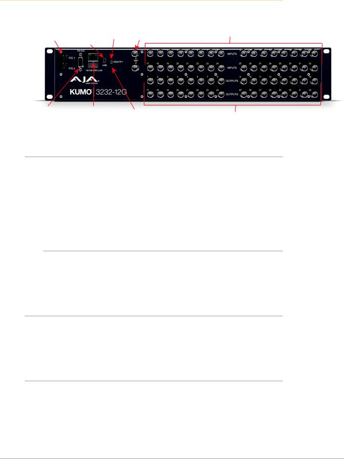
KUMO Router Connections
Figure 1. KUMO Rear Panel Connections (3232 shown, other models similar)
Redundant 12 VDC |
USB Port |
|
|
|
REF BNCs |
SDI Video Inputs 1-32 |
Power Supplies |
Identify Ext Ref Video |
(Top Two Rows) |
||||
PS1 & PS2 |
(Newer |
LED |
Looping |
|
||
|
KUMOs) |
|
|
|
|
|
|
|
|
|
|
|
|
RS-422 Serial |
RJ-45 Ethernet |
Resessed |
SDI Video Outputs 1-32 |
|
9 Pin Female |
10/100/1000 |
|||
Reset Button |
||||
D Connector |
LAN Connector |
(Bottom Two Rows) |
||
|
PS 1 & PS 2 Power Connectors
Power to the KUMO unit is supplied by an external power supply module that accepts a 110-240VAC, 50/60Hz power input and supplies +12 VDC to KUMO via connector PS1 or PS2. One power supply is provided, and it may be connected to either of the two power connectors. An optional second power supply can provide redundancy to help protect against outages.
IMPORTANT: The power connector has a latch, similar to an Ethernet connector. Depress the latch (facing the outside edge of the KUMO device) before disconnecting the power cable from the unit.
Power Loss Recovery
If KUMO experiences a loss of power, when power is restored the router returns to the previous state of all source to destination crosspoints, and all configured source and destination names are retained. If a KUMO control panel configured with a KUMO router loses power, when power is restored the control panel’s configuration is retained, and button tallies will return to their previous states.
RJ-45 Ethernet Connector
The RJ-45 Ethernet connector allows you to connect KUMO to an Ethernet 10/100/1000 Ethernet LAN using CAT5 cable and access KUMO’s built in web server. Multiple configurations are possible, including standalone control, a local LAN, or a WAN. This also allows control over the network using GVG Native Protocol.
ID and Reset
The ID (Identification) LED lights when you use the web interface to identify the KUMO unit you are controlling. The Reset button (pinhole) below the LED allows a safeboot reset of the unit as explained in "Safeboot Reset" on page 31.
KUMO SDI Routers and Control Panels v4.5 |
7 |
www.aja.com |

REF BNC Connector
The REF BNC connector is the looping input for synchronizing the crosspoint switch timing of KUMO to your house video signals. Apply an analog NTSC, PAL, or Tri-level sync signal to this input. Be sure to terminate the second BNC with a 75 Ohm terminator, or if you loop to other equipment terminate the last connected device.
When reference is present, KUMO will switch at the SMPTE RP168 designated switch point with respect to the reference input. If no reference is present, the KUMO will switch at random times.
Video Inputs and Outputs
Depending on your KUMO model, up to 64 SDI video inputs and outputs can be connected to the video input and output BNC connectors.
Normal Mode
In Normal mode, BNC inputs and outputs have a one-to-one relationship with the SDI signals being routed.
Dual and Quad Modes
In Dual mode, inputs and outputs use adjacent pairs of BNCs for each routed signal. In Quad mode, four adjacent BNCs are used for each routed signal. See
"Mode Selection" on page 24.
RS-422 Connector
KUMO includes an RS-422 female DB-9 connector for making serial connections to other equipment. This control connection enables interoperability with other devices, including those that use GVG Native Protocol. See "RS-422 Control Specifications (Routers)" on page 55 for more information.
Older Model RS-422 Adapter
Older KUMO 1604, 1616, and 3232 routers (serial numbers ending in -R0) needed an RS-422 adapter for proper serial control operation (Figure 2) This adapter was shipped with those older model routers. Be aware of this fact if your facility has a mixture of older and newer KUMO routers that use RS-422 control.
NOTE: Only older KUMO 1604, 1616, and 3232 routers with a serial number ending in -R0 require this adapter. KUMO routers with serial numbers ending in -R1 or higher do NOT require the adapter. This adapter is also NOT needed for any KUMO 6464 model router.
Figure 2. RS-422 Adapter
KUMO SDI Routers and Control Panels v4.5 |
8 |
www.aja.com |

KUMO Control Panel Connections
Similar to the KUMO router, KUMO CP has an RJ-45 Ethernet connector and power supply connectors, but has no BNC connectors and no RS-422 port.
KUMO Control and Monitoring
The KUMO router user-interface provides powerful remote setup, control, and monitoring with:
•Zero-configuration Bonjour Protocol and support for UPnP networking protocols
•Remote web browser control interface via Ethernet
•Optional KUMO CP (32 button) and KUMO CP2 (64 button) hardware control panels, each unit able to control up to four KUMO routers
NOTE: The 32 button KUMO CP hardware Control Panel can be used with a KUMO 6464 router operating in Normal mode, but can only control the first 32 Inputs and Outputs. The KUMO CP can be used to fully control a KUMO 6464 that
is operating in Dual or Quad mode. Control of KUMO routers in all modes is available via the KUMO CP and CP2 button hardware panel, web browser, Ethernet control, and RS-422.
•GVG Native Protocol built-in to allow serial or LAN interconnection (one RS-422 or up to ten Ethernet) and interoperability with other equipment. Specifically, KUMO can be controlled by the SMS 7000 portion of the GVG Native Protocol. For details, refer to: "GVG Native Protocol Support" on page 54.
Default Network Settings
KUMO routers and control panels ship with DHCP enabled, making system operation possible simply by connecting the KUMO device’s Ethernet cabling.
In addition, temporary default static IP addresses can be activated for initial KUMO system configuration. See "KUMO Temporary Static IP Address" on page 13.
In This Manual
Chapter 1: Introduction lists features and gives a general description of the product.
Chapter 2: Installation details KUMO installation, connections, and networking configuration options.
Chapter 3: Web Browser User Interface provides complete instructions for controlling and monitoring the KUMO router from a computer.
Chapter 4: KUMO Remote Control Panel details the configuration and operation of the optional KUMO CP Control Panel.
Appendix A: Specifications lists technical specifications for the product. Appendix B: Safety and Compliance information.
Warranty and Index
KUMO SDI Routers and Control Panels v4.5 |
9 |
www.aja.com |
Chapter 2 – Installation
Overview
KUMO SDI routers are easy to set up and use. All of the steps for KUMO installation and configuration are documented in this chapter, summarized as follows:
1.Install the chassis in an appropriate rack. If you are mounting multiple KUMO units, try to place them visually in the same area so if you communicate with them via a network attached computer, you can use the KUMO’s Identify feature to flash the corresponding LED of the unit you’re communicating with. Ensure you have an Ethernet cable routed to where the KUMO will be placed.
2.Assemble the Ethernet network connections to a closed network or LAN using Cat 5 Ethernet cable and any required switches and hubs.
3.Connect the KUMO to power, connecting the power cord to mains AC.
4.If necessary, configure device network settings for operation in your facility.
5.Cable the system SDI video source and destination equipment and reference signals.
6.If operating with Dual Link or Quad Link signals, select the appropriate KUMO operating mode.
Warning! Do not defeat the safety purpose of the grounding-type plug
Caution! To meet safety regulations for leakage current when using redundant power supplies, connect the KUMO dual power supplies to separate branch circuits
What’s In The Box?
When you unpack your AJA KUMO SDI device, you’ll find the following components:
•KUMO SDI router or KUMO control panel
•AC adapter and AC power cord
Please save all packaging for shipping KUMO should you wish to do so when moving or sending it in for service.
KUMO Chassis Installation
Space Requirements
When planning equipment locations and mounting methods, take into account the size of the chassis. KUMO devices are designed for EIA 19” equipment rack mounting. See "Appendix A Specifications" for exact dimensions of each router model.
KUMO SDI Routers and Control Panels v4.5 |
10 |
www.aja.com |
Plan adequate space for cable routing from the back of the router chassis. Ensure that SDI video cable connectors will not be stressed and that cables are not bent or crimped in the process.
Cooling Requirements
When rack mounting or stacking multiple KUMO chassis, ensure there is adequate airspace for cooling around the KUMO units. Note the location of cooling vents on all equipment next to the KUMO and ensure none are obstructed.
Power Requirements
•Input Voltage: 110-240VAC, 50/60Hz
•Optional redundant power supply
Caution! KUMO is designed to take advantage of its chassis to aid in cooling. It is common and expected for the densely populated chassis to have a warm front panel in normal, active operating conditions.
Warning! Do not open the chassis. There are no user-serviceable parts inside. Opening the chassis will void the warranty unless performed by an AJA service center or licensed facility. Remove the brick power supply AC line cord(s) from mains power when moving the unit
Physical Equipment Setup
1.Connect power supplies (1 or 2 for redundancy) to KUMO routers and control panels.
IMPORTANT: The power connector has a latch, similar to an RJ-45 Ethernet connector. Depress the latch (facing the outside edge of the KUMO device) before disconnecting the power cable from the unit.
1.Connect source and destination SDI equipment (this step can be deferred).
2.Connect network:
•Direct Connection: connect a KUMO router to a KUMO CP (if used), or to a Mac or PC, via an Ethernet Cable.
•LAN Connection: connect a KUMO router (and a KUMO CP if used) to a hub or switch and connect a PC or Mac to the same LAN via a hub or switch.
NOTE: KUMO devices are compatible with both CAT-5 straight-through and cross-over Ethernet cables—they automatically detect whichever is used.
3.Proceed to your desired network configuration method using one of the procedures presented later in the chapter.
Quick Start Configuration
Default Auto Configure KUMO Router and Control Panel
If you purchased a KUMO control panel along with a KUMO router, the easiest way to get your system operating is to simply direct connect them with a single Ethernet cable and power up both units.
KUMO SDI Routers and Control Panels v4.5 |
11 |
www.aja.com |

NOTE: The KUMO 6464 router in Normal mode (64 sources and destinations) can be fully controlled with the newer KUMO CP2. The original 32 button KUMO CP hardware Control Panel can fully control a KUMO 6464 router operating in Dual or Quad mode. A 32 button KUMO CP can control first 32 Inputs and Outputs of a KUMO 6464 router operating in Normal mode.
KUMO devices are compatible with both CAT-5 straight-through and cross-over Ethernet cables. The KUMO CP will use an Auto Configure function to set itself up to operate with the KUMO router it is directly connected to. The KUMO CP panel buttons will light and, if SDI BNC connections have been made, you will be able to route sources to destinations.
Figure 3. KUMO Router Direct Connection to KUMO CP
KUMO CP |
|
KUMO Router |
|
|
|
|
Direct Cat 5 |
|
|
Ethernet Cable |
|
|
Connection |
|
The KUMO CP Auto Configure assigns Router Select Button 1 to the attached router.
NOTE: A KUMO CP that has had its network settings configured previously will not use automatic configuration to find a directly connected KUMO router. However, you can force the KUMO CP to enter into Auto Configuration Mode by pressing the RTR 1 and SHIFT DEST buttons simultaneously for four seconds.
DHCP on an Existing Network
Another easy way to get your KUMO system operating is to connect KUMO routers to an existing network configured with a DHCP server. When the units reset during power up, they will see the DHCP server and automatically be given compatible IP network settings. If auto discovery is configured on a computer on that network, that computer will be able to find and control the KUMO router via a web browser (see below).
Computer Auto Discovery
Computers can support network auto discovery, which makes the network configuration process easy. Two methods of connecting using this technique are described below.
Older Mac OS Configuration with Safari Browser Using Bonjour
Mac OSX Safari browser versions 10 and earlier have Bonjour functionality built-in, which can be used to auto-detect and connect to an Ethernet device like a KUMO Router.
NOTE: Apple removed Bonjour support from Safari versions 11 and higher.
To find a KUMO router using Bonjour on a supported version of Safari:
1.Ensure the KUMO to be controlled is powered up and connected via Ethernet (directly to a Mac or via LAN).
2.Start Safari browser on a Mac.
3.Click on the top menu Bookmark->Bonjour->Webpages drop-down and click on a listed AJA KUMO router or control panel.
NOTE: If Bonjour is not visible in the Bookmark drop-down, go to Safari->Preferences- >Advanced and check the “Include Bonjour in the Bookmarks menu” checkbox.
KUMO SDI Routers and Control Panels v4.5 |
12 |
www.aja.com |

4.Safari will display the KUMO web user-interface, which you can use to control and configure that KUMO device.
Windows PC Configuration using UPnP
If your Windows PC supports UPnP protocols (most do) and UPnP network discovery service is enabled (refer to your Microsoft Windows documentation), you can control KUMO routers by simply selecting one from a device list:
1.Ensure the KUMO to be controlled is powered up and connected via Ethernet (directly to the PC or via LAN).
2.Use your Windows Control Panel or File Explorer to go to Computer- >Network.
3.Look at the list under “Other Devices”—double click a KUMO’s name to launch your Windows PC’s default browser.
4.The browser will display the KUMO web user-interface, which you can use to control and configure that KUMO device.
Network Configuration via USB
KUMO devices equipped with USB ports can configured for network operation using AJA's eMini-Setup utility program. The general procedure is:
1.Acquire eMini-Setup from the AJA website and install the eMini-Setup application onto a computer.
2.Connect the KUMO to that computer’s USB port.
3.Launch the eMini-Setup application.
4.Go to the Network tab where the IP address settings are displayed. You can use the existing DHCP assigned IP address, or it can be changed manually.
5.You can also use eMini-Setup to load firmware to the device, although this can also be done quickly and easily using the web browser interface.
See "Chapter 5 eMini-Setup" on page 40 for additional information.
KUMO Temporary Static IP Address
KUMO devices also offer a factory default static IP address, allowing a direct and fail-safe way to connect via a computer connected to KUMO either directly or via a LAN connection. The computer you use will need to be set to a static IP address that is compatible with the KUMO temporary IP address. Once connected, the KUMO device’s network settings can be reconfigured to work with your facility network. The KUMO default static IP address is temporary and is intended only to allow an initial connection.
NOTE: All KUMO routers and control panels have the same temporary static IP address, so more than one device set to this default cannot reside on the same network simultaneously. Work with only one device at a time.
Table 1. KUMO Device Temporary Static IP Address Values
Device |
IP address |
Subnet Mask |
|
|
|
KUMO Router and KUMO CP |
192.168.101.1 |
255.255.255.0 |
|
|
|
NOTE: The default static address is temporary and will be disabled the next time KUMO restarts. Any changes in the Network configuration will be saved upon restart.
KUMO SDI Routers and Control Panels v4.5 |
13 |
www.aja.com |

To set KUMO to its temporary static IP address:
1.Power up the KUMO device and wait for it to boot normally.
2.Set the KUMO device to its static IP address:
•For a KUMO router, insert a straightened paper clip or similar device into the reset slot on the rear and hold for five seconds and then release. The KUMO will restart with the default IP. When the KUMO router default IP is set the Identify LED will blink.
•For a KUMO CP/CP2, press and hold the two SHIFT buttons on the panel for five seconds and then release. When the KUMO CP default IP is set, the Source and Destination buttons will flash alternately.
NOTE: If a KUMO webpage on a computer is open when that KUMO device is reset, the information displayed on the webpage is not updated automatically.
Figure 4. KUMO Router and KUMO CP Default Static IP Setting
KUMO Control Panel Press Both Buttons
KUMO Router
Recessed Button
Under Slot
IMPORTANT: Be sure to record your computer’s existing TCP-IP settings before the next step so that you can return the computer to normal operation after this procedure.
3.Configure your computer to 192.168.101.X. Do not use .1 at the end of the address to avoid duplicate IP addresses.
4.Start a web browser and enter 192.168.101.1 as the web address. This is the KUMO temporary static IP address.
5.Once you’ve connected using the static IP, you can then enter a desired network configuration using the KUMO device’s Network tab.
Network Configuration In Depth
A LAN is a shared network that includes other Ethernet devices all attached via a hub or digital switch. LANs may be divided into zones separated by software or hardware routers. Routers may also be used to connect the LAN to an outside wide area network (WAN) such as the Internet. Devices on a LAN have IP addresses which may be fixed and permanent, or dynamically assigned by the network (DHCP with DNS server).
NOTE: Once connected and properly configured, the KUMO router can then be controlled by a web browser or one or more KUMO CP control panels. KUMO and KUMO CP are equipped with zeroconf (Bonjour) and support UPnP networking protocols but initially start up as DHCP active devices. If you are operating on a DHCP server, KUMO will take an assigned IP address and appear on the network.
KUMO SDI Routers and Control Panels v4.5 |
14 |
www.aja.com |

Caution! When attaching KUMO to a standard static IP LAN, you must configure KUMO components with a new, unique IP address. You should first talk to your network administrator and find out how it should be connected (TCP/IP Static IP or DHCP). Your IT department will be able to supply the information you need to install KUMO on a LAN.
KUMO uses TCP-IP network communications and Ethernet connections (a 10/100/1000 Ethernet port) for crosspoint control, status monitoring, and software updates. KUMO devices have an internal HTTP web server that works with a standard web browser on a Mac or PC. An Ethernet cable can also be used to connect an optional KUMO CP (control panel) directly to a KUMO router for operation without a computer.
KUMO devices are compatible with both CAT-5 straight-through and cross-over Ethernet cables—they automatically detect whichever is used.
KUMO’s internal HTTP networking software supports three levels of network control:
•Closed KUMO network – uses Default Auto Configure (KUMO CP), or Bonjour (Mac or PC).
•Auto Configured LAN – employs a Bonjour or UPnP enabled computer/ browser to automatically connect devices and allows KUMO web browser User Interface (UI).
•Standard TCP-IP network – employs DHCP or Static IP addressing and allows the KUMO web-based UI and an unlimited number of KUMO routers and up to 16 KUMO CP control panels.
The following web browsers have been tested and approved for use with KUMO (Bonjour capability is recommended):
•Firefox - latest version on all platforms
•Safari - latest version on Mac and Windows
•Internet Explorer - version 10 and higher on Windows
•Chrome - latest version on all platforms (Bonjour is supported)
Once connected, you can use a web browser to:
•Configure any TCP/IP settings
•Select and name KUMO routers and control panels
•Assign a KUMO panel to be able to control specific KUMO routers
•Name sources and destinations
•Make Source to Destination assignments (signal routing)
•Change router operating mode (Normal, Dual Mode, Quad Mode)
•Set a variety of operational and monitoring options
LAN Connection Using a Hub or Switch
In a LAN connection, connect one or more KUMO routers to your LAN or closed network using Cat. 5 Ethernet cable and an Ethernet hub or switch; then power up the equipment.
KUMO SDI Routers and Control Panels v4.5 |
15 |
www.aja.com |

Figure 5. KUMO Routers on LAN with Web Browser UI
LAN Switches or
Hubs
Control Unlimited KUMO
Routers via TCP/IP
Web Browser
User Interface
Setup and Control Methods
Regardless of direct connection or LAN connection, KUMOs are controlled over a network by connecting to KUMO’s internal web server with a standard web browser on a Mac or PC. To do this you first need to establish a network connection between the computer and the KUMO to be controlled. There are various methods supported for doing this depending on the operating system and/or web browser being used.
When using KUMO in a DHCP or Static IP addressed network, it is best to select and maintain a consistent network scheme. If you use a mix of DHCP and Static IP addresses, inconsistent performance can result. The most stable operation is achieved when all IP addressing is either DHCP or Static
Setup and Control from a Browser on Mac OSX
Safari Browser: Type in KUMO Static IP Address
KUMO offers a factory default static IP address. The default static IP address is temporary and is intended only to allow an initial connection. Once you’ve
connected using the static IP, you can then enter a desired network configuration using KUMO’s Network tab.
NOTE: The default static address is temporary and will be disabled the next time KUMO restarts. Any changes in the Network configuration will be saved upon restart.
1.Set the KUMO to its factory default IP address. See "KUMO Temporary Static IP Address" on page 13 for this procedure.
2.Configure your computer to communicate on the 192.168.101.X subnet as shown below:
IMPORTANT: First record existing TCP-IP settings so that you can return your computer to normal operation after this procedure.
A.Go to your System Preferences>Network and select Ethernet and Configure: Manually.
KUMO SDI Routers and Control Panels v4.5 |
16 |
www.aja.com |

Figure 6. Mac Network Setup Screen (System Preferences -> Network)
B.Input the address information shown below:
•IP Address: 192.168.101.X (do not use .1 in the last octet).
•Subnet Mask: 255.255.255.0
C.Click Apply.
3.Ensure the KUMO device to be controlled is connected to the Mac via Ethernet (directly or via LAN).
4.Start Safari and enter 192.168.101.1 as the web address. This is the KUMO temporary static IP address.
5.Once you’ve connected to KUMO’s web interface, reconfigure KUMO’s network parameters as desired using the KUMO device’s Network tab.
6.Restore your computer to its normal network settings using this procedure and the IP addresses you recorded earlier.
Setup and Control from a Browser on Windows
The easiest methods of setting up a controlling a KUMO device from a PC running Windows are:
•Setup and Control from a Browser on Windows using UPnP
•Setup and Control from a Browser on Windows using a Static IP Address
Windows: Using UPnP (Universal Plug and Play)
This method was covered earlier in this chapter.
See "Windows PC Configuration using UPnP" on page 13.
Windows Browser: Type in KUMO Static IP Address
KUMO offers a factory default static IP address. The default static IP address is temporary and is intended only to allow an initial connection. Once you’ve
connected using the static IP, you can then enter a desired network configuration using KUMO’s Network tab.
KUMO SDI Routers and Control Panels v4.5 |
17 |
www.aja.com |

NOTE: The default static address is temporary and will be disabled the next time KUMO restarts. Any actual changes made to KUMO's Network configuration will be saved and used upon restart.
1.Set the KUMO to its factory default IP address. See "KUMO Temporary Static IP Address" on page 13 for this procedure.
2.Configure your computer to 192.168.101.X as shown below (this example is for a PC running Windows 7 connected directly to KUMO, other Windows versions use similar procedures):
A.Use Control Panel to access your Local Area Network properties. In Windows 7 the path is:
• Control Panel > Network and Sharing Center
B.Then, under “Connections” click on the Local Area Connection for the PC’s Ethernet port.
Figure 7. Windows 7 Network Configuration Screens
C.In the resulting General dialog screen, select the Properties button.
D.Then on the Networking tab, select Internet Protocol Version 4 and click the Properties button below.
IMPORTANT: Record your computer's existing TCP-IP settings. You will later need to restore these original settings so that you can return your computer to normal operation after this procedure.
E.Finally, click the “Use the following IP address:” radio button and enter the IP Address and Subnet Mask below:
•IP Address: 192.168.101.X (do not use .1 in the last octet).
•Subnet Mask: 255.255.255.0
F.Click the OK button to store the changes.
3.Connect the Windows PC to KUMO’s RJ-45 port (either direct or through your LAN)
4.Point your web browser to 192.168.101.1 as the web address. This is the KUMO temporary static IP address.
5.Once you’ve connected to KUMO’s web interface, reconfigure KUMO’s network parameters as desired using the KUMO device’s Network tab.
KUMO SDI Routers and Control Panels v4.5 |
18 |
www.aja.com |
6.Restore your computer to its normal network settings using this procedure and the IP addresses you recorded earlier.
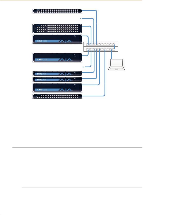
Larger System Control Configurations
Figure 8. Multiple KUMO Routers and KUMO CPs with Web Browser UI Control.
Multiple KUMO CPs anywhere on the network, each CP can control up to four compatible KUMO routers at a time.
Compatibility:
*KUMO CP2 can control any KUMO Router in any mode.
*KUMO CP can control any KUMO Router except 6464 in Normal mode.
LAN Switches or Hubs
Multiple KUMO Routers anywhere on the network, controllable by any compatible KUMO CP.
Web Browser
User Interface
NOTE: The 32 button KUMO CP hardware Control Panel cannot be used with a KUMO 6464 router operating in Normal mode (only 32 buttons for 64 sources and destinations). However the KUMO CP can be used when the KUMO 6464 is operating in Dual or Quad mode. Control of the KUMO 6464 router in all modes is available via the KUMO CP2 64 button hardware panel, web browser, Ethernet control, and RS-422.
If the KUMO will be attached to a WAN, talk to your IT administrator and obtain the details on how to configure the KUMO (DHCP or static IP).
TCP-IP Network Connection
KUMO supports traditional TCP-IP networking through DHCP or Static IP addressing.
IMPORTANT: When using KUMO in a DHCP or Static IP addressed network, it is best to select and maintain a consistent network scheme. If a mixture of DHCP and Static IP addresses are used, inconsistent performance can result. The most stable operation is achieved when all IP addressing is either DHCP or Static.
Default DHCP Configuration
DHCP is the default initial configuration routine for KUMO devices. If you start up on a DHCP network, KUMO will accept assigned IP addresses. After DHCP initialization, use your zeroconf browser to view the KUMO web page and view the assigned IP address.
KUMO SDI Routers and Control Panels v4.5 |
19 |
www.aja.com |

Static IP Configuration
If your IT administrator prefers an assigned IP address that is fixed (called a “Static IP), you will need to set network parameters using the KUMO UI Network screen where you will enter:
•IP address type—Static IP
•a unique IP address
•the Subnet Mask and default gateway IP address (your LAN’s router that does the network's routing)
You will need to press the Enter key on the keyboard for every field changed. Press the Update Network Settings button when all fields are complete.
Figure 9. KUMO User Interface Network Tab
Select KUMO to Control from Web Page
Each KUMO device has a built in web server that generates a web page. KUMO devices see each other on the network and list those other KUMO devices in their web pages. From the Home screen, use the pulldown menu in the upper left to see all of the KUMO devices present on the local LAN and select the router you want to control, or select the KUMO CP you want to use.
Figure 10. KUMO Router Selection
Assign KUMO CP and CP2 to Control KUMO Routers
With multiple KUMO routers and KUMO control panels on the same network, you can assign which routers are able to be controlled by a panel by configuring the four Router Select buttons on the panel. On the KUMO control panel web page, go to the Home screen, click on the box below the RTR button, and select the KUMO router from the drop-down list.
KUMO SDI Routers and Control Panels v4.5 |
20 |
www.aja.com |
Figure 11. KUMO Control Panel Router Button Assignment
Locating a Specific KUMO Device on the Network
Identify Button
Click on the web UI Identify button to find the physical location of the currently controlled KUMO router or panel.
The web browser button will alternate between blue and gray background color in Identify mode. Click again to turn the Identify function off.
•On a KUMO router, the Identify LEDs on the front and back will flash, enabling quick physical location of the router in a populated rack of equipment.
•On a KUMO CP, the Source and Destination button rows will flash alternately.
Figure 12. KUMO Router Identify LEDs.
Identify LED
(Front Panel)
Identify LED
(Rear Panel)
KUMO SDI Routers and Control Panels v4.5 |
21 |
www.aja.com |
Loading...